Evidence of new twinning modes in magnesium questioning the shear
paradigm
C. Cayron1, R.E. Logé1
Twinning is an important deformation mode of hexagonal close-packed metals. The
crystallographic theory is based on the 150-years old concept of simple shear. The habit plane of
the twin is the shear plane; it is invariant. Here we present Electron BackScatter Diffraction
observations and crystallographic analysis of a millimeter size twin in a magnesium single crystal
whose straight habit plane, unambiguously determined both the parent crystal and in its twin, is
not an invariant plane. This experimental evidence demonstrates that macroscopic deformation
twinning can be obtained by a mechanism that is not a simple shear. Beside, this unconventional
twin is often co-formed with a new conventional twin that exhibits the lowest shear magnitude
ever reported in metals. The existence of unconventional twinning introduces a shift of paradigm
and calls for the development of a new theory for the displacive transformations.
Keywords : Deformation twinning, magnesium, titanium, angular distortive matrix.
Deformation twinning is an important deformation mode in hexagonal-close packed (hcp) materials,
such as titanium, zirconium and magnesium alloys and is the subject of active research. The
considered general theory is 150 years old and is based on the concept of simple shear. In 1867,
Thomson and Guthrie Tait1 defined a simple shear as “the property that two kinds of planes (two
different sets of parallel planes) remain unaltered, each in itself”, which lead to the nomenclature
(K1,1,K2,2) introduced in 1889 by Mügge2,3.The first plane is the shear plane K1; it is untilted and
undistorted; it contains the shear direction 1. The second plane K2 is undistorted but rotated. The
direction 2 belongs to K2 and is perpendicular to the intersection between K1 and K2. Between 1950
and 1970, the theory of twinning was mathematically developed and refined with linear algebra4-9.
The theory uses three matrices: the simple shear matrix S deduced from (K1,1), the correspondence
matrix C, and the parent/twin misorientation matrix T. More details on these matrices are given in
the preliminary section of Supplementary Equations. Among the numerous but finite possible
correspondence and shear matrices resulting from the calculations, only those with the lowest shear
magnitude are considered as realistic. As an instantaneous and homogeneous shear is not possible
at reasonable stresses10, the simple shear was assumed to be produced by the coordinate
propagation of “twinning dislocations” created by complex “pole mechanisms”11-13. The
generalization of dislocations as a fundamental part of the transformation mechanism really came
1 Laboratory of ThermoMechanical Metallurgy (LMTM), PX Group Chair, Ecole Polytechnique Fédérale de Lausanne (EPFL),
Rue de la Maladière 71b, 2000 Neuchâtel, Switzerland

with the introduction of the “disconnections”14,15. All these cited models are based on the shear
paradigm; they have dominated the theoretical developments of deformation twinning over the last
seventy years.
The formation of {1012} extension twins without straight shear plane was recently observed by in-
situ Transmission Electron Microscopy (TEM) in magnesium nano-pillars16. The twins are
characterized by a parent/twin misorientation of 90° around the a-axis, instead of 86° for the
conventional extension twins in bulk magnesium. These observations, and earlier molecular-dynamic
simulations of the nucleation stage of extension twinning17,18, lead some researchers to propose a
new twinning mechanism based on “pure shuffle”, or equivalently “zero shear”16,19. This mechanism
is the subject of an intense debate20. One way to reduce the controversy was to admit that the “zero
shear” mechanism “distinctively differs from any other twinning modes” and that “this should not be
deemed as the failure of the classical theory”19. Is that correct? Is the unconventional (90°, a) twin an
exotic case limited only to extension twinning in hcp metals, and even more specifically to the
nucleation step or to nano-sized samples? It was recently shown that the unconventional “zero-
shear” (90°, a) and conventional shear (86°, a) twins actually result from the same distortion because
they differ just only by an obliquity correction21. The model assumes that the atoms move as hard-
spheres, and it calculates for a given orientation relationship the analytical forms of the atomic
trajectories, lattice distortion, and volume change. A similar approach was used to model {1011}
contraction twinning22. The volume change is a direct consequence of the hard-sphere assumption.
Indeed, the Kepler conjecture (demonstrated by Hales23) implies that all the intermediate states
between an hcp structure and its twin have a density lower than that of hcp. The volume change is
not negligible; for magnesium, it is 3% for extension twinning21 and 5% for contraction twinning22.
The same approach was used for martensitic transformations between fcc, bcc and hcp phases24. It
should be noted that a volume change is not compatible with a simple shear. Beside the volume
change, the calculations proved that the habit plane is not invariant; it is untilted but distorted, and
restored only when the process is complete. Thus, one can ask whether for some twins the interface
plane could be transformed into another crystallographic plane. This would then confirm that
deformation twinning in hcp metals is not the result of a simple shear distortion. Here we present
the experimental proof that such an unconventional twin exists; it is millimeter-sized and appears in
a bulk magnesium single crystal. It will be also shown that this twin is often co-formed with a new
conventional twin on {2132} plane that exhibits the lowest shear value ever reported for hcp metals.
A piece of magnesium single crystal was cut with a diamond saw, mechanically polished and then
electro-polished. Bands of twins are visible in optical microscopy at the side where the sample was
cut. A second cut was performed perpendicularly to the first one, and here again, large bands of
twins appeared at the cut side, which shows that the twins were induced by friction during the
cutting step. The two cut sections are called A and B in the rest of the paper. Electron BackScatter
Diffraction (EBSD) maps were acquired on the area containing the larger twins in the A and B
sections. They are shown in Fig. 1 and Extended Data Fig.1, respectively. In order to facilitate the
identification of the twins all along this manuscript, some colors were attributed to the different
types of twins, independently of the absolute orientation of the sample. The parent single crystal is
colored in grey and the conventional extension twins in blue. New twins, colored in green, are
formed close to the conventional extension “blue” twins. They are often co-formed with twins

colored in yellow, orange and red. The green and yellow/orange/red twins are twins that have never
been reported in literature.
Before detailing the crystallographic characteristics of these new twins, it is worth recalling, with the
example of the conventional extension blue twins of Fig. 1, how crystallographic information can be
read from the experimental EBSD data and their associated pole figures. The extension twins are
identified in the EBSD maps by their (86°, a) misorientations with the parent crystal, as shown by the
rotation of 86° around the a-axis marked by the dashed circle in Fig. 2b and c. The atomic
displacements during extension twinning are such that the basal {001} plane and prismatic {100}
plane are exchanged, as illustrated by the exchange between of the positions of the planes marked
by the triangles and squares in the pole figures shown in Fig. 2a and b. The habit plane of the
extension twins is the “diagonal” {012} planes located between these two planes. Indeed, the traces
of the habit planes agree perfectly with the expected {012} planes, as shown by the fact that spots
marked by circles in Fig. 2d are perpendicular to the trace of the extension twins noted HPE1 and
HPE2 in Fig. 1. The same results are obtained with the EBSD map acquired on section B, shown in
Extended Data Fig.1, with pole figures in Extended Data Fig.2. The {012} habit plane of the extension
twins appears in the EBSD map as a plane that is both untilted and undistorted, i.e. fully invariant, in
agreement with the simple shear theory, but actually, if the process of lattice distortion is
considered in its continuity, the atomic displacements are such that the {012} plane cannot be
maintained invariant during the distortion; it is only restored when the distortion is complete21. The
conventional extension blue twins do not provide a direct footprint of this continuous process, and
the {012} interface appears as if the {012} plane had been invariant through the process. The
situation will be shown to be different with the “green” twins.
The long millimeter-sized green twins shown in the EBSD map of Fig. 1 are misoriented from the
parent crystal by a rotation angle 58° with a spreading of 4° and a rotation axis close to a + 2b.
This misorientation appears in the histogram of Fig. 1b and c. Twins with similar misorientations
already appeared in the histograms of some previous studies 25,26, but their crystallographic analysis
is very recent27,28. Ostapovets et al.27 interpret them as the result of a complete double {012}-{012}
twinning in which there is no retained traces of the first {012} twins. A different mechanism was
proposed in which the lattice distortion is modelled as a one-step process without the need of a
hypothetical intermediate {012} twin28. Whatever the model, it is agreed27,28 that there is a strong
link between these (58°, a+2b) twins and the (64°, a+2b) {1122} twins frequently observed in
titanium, and that these twins are not predicted by the general theory of twinning8,9 or by the
dedicated Westlake-Rosembaum model29,30. Following our study28, it will be assumed that the (58°,
a+2b) twins result from a unique distortion that is geometrically represented with the supercell X2YG
shown in Fig. 3a. When the parent lattice is rotated by (58°, a+2b) the supercell becomes close to
the initial one, as illustrated in the projection along the axis OY = a+2b of Fig. 3b. The (58°, a + 2b)
prototype configuration is special because the parent vector 𝐎𝐗2 = [200]𝑝 is parallel to the twin
vector 𝐎𝐗2′ = [101]𝑔𝑟, the parent vector 𝐎𝐘 = [120]𝑝 is invariant, and the parent vector
𝐎𝐆 = [101]𝑝 is parallel to the twin vector 𝐎𝐆′ = [200]𝑔𝑟 , with the indices “p” and “gr” given in
reference to the parent and green twin bases. In addition to the parallelism of the directions, the
lengths of the vectors are such that ‖𝐎𝐗2‖ ≈ ‖𝐎𝐗′2‖, ‖𝐎𝐘‖ = ‖𝐎𝐘′‖ and ‖𝐎𝐆‖ ≈ ‖𝐎𝐆′‖. The
(p → gr) distortion associated with the transformation 𝐎𝐗2 → 𝐎𝐗′2, 𝐎𝐘 → 𝐎𝐘′, 𝐎𝐆 → 𝐎𝐆′ is given
by a upper triangular matrix 𝐅ℎ𝑒𝑥𝑝→𝑔𝑟
given in Supplementary equations (15), with details reported

elsewhere28. Its diagonal values are √1+𝛾2
2, 1 and
2
√1+𝛾2, where 𝛾 is the c/a packing ratio. The
principal strains associated with this distortion are -4.2%, 0, and +4.4% in the case of pure
magnesium. The parent/twin misorientation matrix is a rotation of axis OY = [120]p and of angle
𝐴𝑟𝑐𝑇𝑎𝑛(𝛾). It takes the value 58.39° for magnesium; which is expected from the model and very
close to the misorientation observed in the histogram of Fig. 1b and in Fig. 4a and b. The
correspondence matrix 𝐂ℎ𝑒𝑥𝑔𝑟→𝑝
calculated by considering the vectors 𝐎𝐗2, 𝐎𝐘, and 𝐎𝐆, and the
vectors 𝐎𝐗2′, 𝐎𝐘′, and 𝐎𝐆′ expressed in their respective hexagonal bases is given in Supplementary
Equations (17). The same correspondence expressed in the reciprocal space (𝐂ℎ𝑒𝑥𝑔𝑟→𝑝
)∗is the inverse
of the transpose of 𝐂ℎ𝑒𝑥𝑔𝑟→𝑝
; it is in agreement with the fact that the {001} and {112} planes are
interchanged by the twin, as illustrated by the exchange between the triangles and squares in the
pole figures shown in Fig. 4b and c. The details of the calculations of distortion, orientation and
correspondence matrices are given in section 2 of Supplementary Equation and are computed in
part A of the Mathematica program reported in Supplementary Data.
The (58°, a+2b) twins is only a stretch prototype close to the green twins observed in Fig. 1. From a
theoretical point of view, its role is similar to the (90°, a) stretch prototype used in the atomistic
model of the (86°, a) extension twin21, or to the Bain distortion used as a prototype stretch distortion
of the fcc-bcc martensitic transformation in the Phenomenological Theory of Martensite
Transformation (PTMC)31. The usual way to build a conventional twin from the prototype model is to
add a small obliquity correction (few degrees) that compensates the tilt of an undistorted plane in
order to make it fully invariant. After obliquity correction, the distortion becomes a simple shear.
Calculations prove that there are only two possible planes whose tilt can be compensated by an
obliquity correction; they are the planes (212) and (126) as detailed in separate papers27, 28. In both
cases, the rotation axis of the obliquity compensation is 𝐎𝐘 = [120]𝑝. Geometrically, the (212) and
(126) are the two diagonals of the OX2VG rhombus shown in Fig. 3c and d, respectively; they define
two conjugate twinning modes. The shear vector is along the [101] direction in the (212) twin
mode, and along the [3 0 1] direction in the (126) twin mode, as illustrated by the green arrows in
Fig. 3c and d. The shear magnitudes are the same for both modes and close to 0.11 for
magnesium27,28. The new parent-twin misorientation of the (212) twin is a (63°, a+2b) rotation (the
corrected obliquity was 4°), and the new parent-twin misorientation of the (126) twin is a (57°,
a+2b) rotation (the corrected obliquity was 1°). These two twins modes are not reported in the list
of twins predicted by the classical shear theory9; they are however conventional because their lattice
distortions are given by simple shear matrices. By considering these theoretical results, one could
expect that the habit planes of the green twins, noted HP1 and HP2 in the EBSD maps of Fig. 1, and
those of the twins in the EBSD map of Extended Data Fig.1, are two equivalent planes in the family of
the {1122} planes, or in the family of the {1126} planes. Surprisingly, this is not the case. The two
HP1 and HP2 green twins have very close orientations (their disorientation angle is lower than 4°)
but very distinct habit planes, whereas the models27,28 predict only one habit plane per family. In the
pole figures of Fig. 4, the unique plane of type {1126} and the unique plane of type {1122} common
to both the parent crystal and the green twin are encircled; and, as they are close to the x-axis, their
trace on the EBSD map should be vertical in the EBSD map of Fig. 1, which is clearly not the case
(they are at more than 50° away from the vertical direction). So, what are the habit planes of the
green twins? After some attempts we discovered that they are {212}𝑝 planes of the parent crystal
and {012}𝑔𝑟 planes of the green twin crystals. This is shown in Fig. 5a and b by the fact that (i) the

circles around the {012}𝑡 pole are positioned exactly at the same positions as those of the {212}𝑝
poles, and (ii) these common poles are perpendicular to the traces of the habit planes HP1 and HP2
of the green twins shown in the EBSD map of Fig. 1. The {212}𝑝 → {012}𝑔𝑟 correspondence is
expected by the theoretical correspondence matrix (𝐂ℎ𝑒𝑥𝑡→𝑝)∗, as shown by Supplementary Table 2 in
Supplementary Equation; but the EBSD experimental results bring an additional information: the
planes {212}𝑝 and {012}𝑔𝑟 are exactly parallel, which is not the case by considering only the
theoretical prototype (58°, a+2b) stretch distortion given in Supplementary Equations (15). This
experimental result is of prime importance because contrarily to all deformation twins ever reported
in bulk materials, the habit planes of the green twins are not invariant planes; they cannot result
from a simple shear. They are thus called here “unconventional”, and noted (58°, a+2b). Additional
crystallographic information is required to get a better understanding of these new twins. It was
found that that the green twins share with the parent crystal a common direction of type ⟨201⟩, i.e.
⟨2243⟩ in the four index Miller-Bravais notation, and that this direction, marked by a blue circle in
Fig. 5c, lies in the habit plane whose normal direction is encircled in red in Fig. 5b. The EBSD map
acquired on section B and reported in Extended Data Fig.1 with pole figures in Extended Data Fig.3
presents green twins with exactly the same crystallographic characteristics as those of Fig. 1. Some
TEM observations were also realized on a green twin; they do not reveal additional internal twinning
or important dislocation arrays, as shown by the TEM bright field image in Extended Data Fig.4.
Let us build a crystallographic model of the (58°, a+2b) green twins. The parent/twin misorientation
should be close (within few degrees) to that of the (58°, a+2b) stretch prototype previously
discussed. Their habit plane is the 𝒈0 = (212)𝑝 plane that is transformed into the (012)𝑔𝑟 plane.
The (212)𝑝 (012)𝑔𝑟 distortion occurs by the displacements of the atoms located in the upper
layer l = 1/3 of the plane (212)𝑝 as shown in in Fig. 6. In the (212)𝑝 plane, the direction [101]𝑝 is
4% elongated to be transformed into [200]𝑔𝑟, and the angle p = ([101]𝑝, [021]𝑝) decreases by 3°.
The details of the calculations are in section 2 of Supplementary Equations. Now, the distortion
should be obliquity-corrected such that the plane 𝒈0 and the direction 𝒖0 = [021] are
simultaneously maintained unrotated. This direction [021] was chosen among the equivalent
⟨2243⟩ directions because it lies in the (212)𝑝 plane. From these conditions and the initial model of
the (58°, a+2b) prototype, it is now possible to build a crystallographic model of the green twins. The
calculations are detailed in section 2 of Supplementary Equations and are computed in part B of the
Mathematica program reported in Supplementary Data. They prove that the obliquity angle is 3.3°.
The nine components of the obliquity-corrected distortion matrix, as function of the packing ratio,
are given in Supplementary Equation (23). The new parent/twin misorientation of the obliquity-
corrected twin is a rotation given in Supplementary Equation (25); the rotation angle is 60.7° and
the rotation axis is less than 2° away from the a+2b axis. The difference of the orientation between
the twins formed directly by the prototype model and those formed with the obliquity-corrected
version is low (58.4° / 60.7°) and lies in the spreading of the misorientation histogram shown in Fig.
1b. This spreading exists for all observed green twins. It was noticed that the isolated green twins
have a greater tendency to exhibit a 58° misorientation with the parent crystal, such as the one
marked by green arrow in Fig. 1a, whereas the green twins that are co-formed with yellow twins
tend to exhibit misorientations more centered in the range 60-61°; it is the case in the area marked
by dashed green rectangle in Fig. 1a, as shown by the local misorientation histogram given in Fig. 1e.
Gradient of orientations between 58° and 62° are rainbow-colored in Fig. 1d. The yellow twins seem

to stabilize the unconventional green twins such that the condition 𝒈0 = (212)𝑝 // (012)𝑔𝑟 is
fulfilled. The following part is devoted to the crystallographic properties of the yellow twins and their
role in the stabilization of the green twins.
The yellow twins have a misorientation with the green twins with which they are co-formed close to
(86°, a). This shows that the yellow twins are linked to the green twins by a sort of extension
twinning. However, the yellow twins, as the green twins, also result from a deformation twinning
mechanism of the parent crystal. The misorientation of the yellow twins with the parent crystal is
found to be close to a rotation of 48° around an axis of type <241>, as illustrated in Fig. 1b and c for
the EBSD map of section A, and in Extended Data Fig.1b and c for the EBSD of the section B. The
habit planes with the parent crystal are the same as those of the green twin; they are {212}𝑝 planes.
Consequently, contrarily to the green twins for which the habit plane is a distorted plane {212}𝑝 →
{012}𝑔𝑟, the habit plane of the yellow twin is a restored plane {212}𝑝 → {212}𝑦𝑒, as shown in the
pole figures of Fig. 5b. Indeed, in this figure, the circle noted “HP1” is around the {212} plane that is
common to both the parent and the yellow twins co-formed with the green twin lying along HP1 in
Fig. 1; and the circle noted “HP2” is around the {212} plane that is common to both the parent and
the red twin co-formed with the green twin lying along HP2 in Fig. 1. These features are also
observed with the three habit planes identified in the EBSD map of section B, as shown in the {212}
pole figure of Extended Data Fig.3 of the yellow, orange and red twins co-formed with the green
twins shown in Extended Data Fig.2. Thus, the yellow twins are conventional because their habit
plane is a crystallographic plane that is common to both parent and twin crystals. However, to the
best of our knowledge, no twin with a shear plane of type {2132} has ever been reported by the
classical models of deformation twinning9. It is thus important to get additional crystallographic
information on this twin and its link with the green twin. It was noticed that the axis 𝒖0 = [021]
that was left invariant during the (𝑝 → 𝑔𝑟) twinning is also left invariant by the (𝑔𝑟 → 𝑦𝑒) twinning,
i.e. this axis is common to the three crystals: the parent crystal, the green twin and the yellow twin.
This is shown by the encircled directions in the pole figure Fig. 5c and in the pole figure of Extended
Data Fig.3c.
Let us build a crystallographic model of the yellow twins. One could have imagined building such a
model by considering that the yellow twins are extension twins of the green grains. However, it is
mathematically impossible to build a conventional twin by composing the distortion matrix of the
(58°, a+2b) unconventional green twin with that of a conventional (86°, a) extension twin because
the terms in the former are irrational and those of the latter are rational, which means that their
composition cannot give a rational matrix. This apparent issue is solved by considering that the
yellow twins are not in a conventional extension twin relationship with the green grains, but with a
relation that is derived from it by a small obliquity correction. The green twins induce a planar
distortion (212)𝑝 → (012)𝑔𝑟, and the obliquity-corrected extension twin should be such that it
induces the reverse planar distortion (012)𝑔𝑟 → (212)𝑦𝑒. The idea is therefore to maintain untilted
the plane (012)𝑔𝑟 and invariant the direction 𝒖0 = [021] during (𝑔𝑟 → 𝑦𝑒) twinning. The
calculations are detailed in section 3 of Supplementary Equations. They show that an obliquity of
1.1° around the common axis 𝒖0 is sufficient to make the conventional extension twins compatible
with the experimental results. This obliquity is so small that it is not possible to distinguish whether
the green/yellow relation is a conventional (86°, a) twinning or its derived version. The new

distortion matrix and the misorientation matrix associated with the (𝑔𝑟 → 𝑦𝑒) relation are given in
equation (40) and (42) of Supplementary Equations.
Now, it is possible to compose the correspondence, distortion and orientation matrices of the
(𝑝 → 𝑔𝑟) twin with those of the (𝑔𝑟 → 𝑦𝑒) twin. The calculations are detailed in section 4 of
Supplementary Equations. The calculated misorientation between the yellow twin and the parent
crystal is a rotation of 48.7° around the [221]𝑝 axis, which is in perfect agreement with the 48°
misorientation experimentally determined in the histograms of Fig. 1b and c, and those of Extended
Data Fig.1b and c. The distortion matrix is a shear matrix, as expected for a conventional twin. The
shear vector is [547]𝑝
, i.e. of type ⟨1237⟩𝑝. The shear value is 𝑠 = √7
48
|3−𝛾2|
𝛾, which is equal to 0.078
for ideal hard-sphere packing and 0.084 for magnesium. This twinning mode was not predicted by
the classical theory of deformation twinning; the shear magnitude is, to our best knowledge, the
lowest value ever reported for deformation twinning of metals.
In summary, the EBSD study on a saw-cut magnesium single crystal put in evidence unconventional
millimeter-size twins localized close to conventional extension twins. The parent/twin misorientation
is (58°, a+2b). This twin is unconventional because its habit plane is not invariant; it is a {212} plane
untilted but distorted and transformed into a {012} plane. This twin is often co-formed with another
twin and linked to it by an unconventional type of extension twinning. This co-formed twin is a
conventional (shear) twin of the parent crystal, but the twin mode is new; the parent/twin
disorientation is (48°,⟨221⟩); and the calculations show that the associated distortion matrix is a
{212} ⟨547⟩ shear with a magnitude of only 0.084. Some researchers recently proposed a “pure
shuffle” model to interpret their observations of (90°, a) extension twins in magnesium nano-pillars,
but they assumed that their discovery was limited to this special twin and was not a “failure of the
classical theory”. The present evidence of macroscopic unconventional twins with {212} {012}
interface calls for reconsidering the theory of deformation twinning because the initial paradigm of
simple shear is not consistent with the present observations. An approach based on hard-spheres
had been followed for the last years and applied to martensitic transformations and to extension
and compression twinning in magnesium21-24; it proposes to shift the shear paradigm while
preserving the essential displacive features of these transformations32. Once generalized and
formalized, it could constitute one of the possible alternatives to the shear-based theories.
Methods
The magnesium single crystal was bought at Goodfellow Inc. It is the same sample as the one used in
the theoretical study of extension twinning21. Two perpendicular cross-sections were cut and called
A and B in the paper. The extension twins and the new twins studied are induced by the disk cutting
with the abrasive disk saw. The two sections were mechanically polished with abrasive papers and
clothes with diamond particles down to 1 m, and then electropolished at 12V with an electrolyte
made of 85% ethanol, 5% HNO3 and 10% HCl just taken out of the fridge (10°C). The EBSD map was
acquired on a field emission gun (FEG) XLF30 scanning electron microscope (FEI) equipped with an
Aztec system (Oxford Instruments). The EBSD maps were treated with the Channel5 software
(Oxford Instruments). The blue, green and yellow/red colors were attributed to the twins by using

the function “Texture Components” with the average Euler angles of each twin and a range angle of
10°.
All the indices of planes and vectors are noted here in the crystallographic hexagonal basis, even if
the calculations detailed in Supplementary Equations sometimes use intermediate orthonormal
bases. The ratio of lattice parameter is = √8/3 for ideal hard-sphere packing and = 1.625 for
magnesium. All the calculations were performed in symbolic form with Mathematica; the computer
program is given in Supplementary Data. The calculations are detailed in Supplementary Equations;
which includes at its end a table (Supplementary Table 2) that summarizes the main equations used
in the paper. The vectors are noted by bold lowercase letters and the matrices by bold capital
letters. The three-index Miller notation in the hexagonal system is used for the calculations and
preferentially chosen to write the results. The four index Miller-Bravais notation is sometimes
written to help the reader to identify the directions or planes that are equivalent by hexagonal
symmetries. Conversion rules33 between the three-index and four-index notations for planes and
directions are (ℎ, 𝑘, 𝑙) = (ℎ, 𝑘, ℎ + 𝑘, 𝑙) and [𝑢, 𝑣, 𝑤] = [2𝑢−𝑣
3,2𝑣−𝑢
3,𝑢+𝑣
3
, 𝑤], respectively. For
example, a = [100]hex, b = [010]hex belong to the set of equivalent directions 1
3⟨1120⟩. The distortion
matrix, the correspondence matrix, and the coordinate transformation matrix are defined in
Supplementary Equations §1. The crystallographic calculations of the (58°, a+2b) twin with its
obliquity-corrected version are developed in Supplementary Equations §2. The crystallographic
calculations of the (86°, a) extension twin with its unconventional version are given in
Supplementary Equations §3. The composition of these two unconventional twins leading to the
new conventional twin is detailed in Supplementary Equations §4. The calculations can be checked
by consulting the Mathematica program in Supplementary Data.
References
1 Thomson, W. & Tait, P.G. Treatise on Natural Philosophy, Cambridge, vol. I (1) 170-171, pp.
105-106 (1867).
2 Mügge,O. Ueber homogene Deformationen (einfache Schiebungen) an den triklinen
Doppelsalzen BaCdCl4.4aq., Neues Jahrbuch für Mineralogie, Geologie und Palaeontologie,
Beilage-Band 6, 274–304 (1889).
3 Hardouin Duparc, O.B.M. A review of some elements for the history of mechanical twinning
centred on its German origins until Otto Mügge’s K1 and K2 invariant plane notation. J. Mater.
Sci. DOI: 10.1007/s10853-016-0513-4 (2017).
4 Cahn, R.W. Twinned crystals. Advanced in Physics 3, 363-444 (1954).
5 Kihô, H. The Crystallographic Aspect of the Mechanical Twinning in Metals. J. Phys. Soc. Japan
9, 739-747 (1954).
6 Jaswon, M.A. & Dove, D.B. The Crystallography of Deformation Twinning. Acta Cryst. 13, 232-
240 (1960).
7 Bilby, B.A. & Crocker, A.G. The Theory of the Crystallography of Deformation Twinning. Proc. R.
Soc. Lond. A. 288, 240-255 (1965).

8 Bevis, M. & Crocker, A.G. Twinning Shears in Lattices. Proc. Roy. Soc. Lond. A.304, 123-134
(1968).
9 Crocker, A.G. & Bevis, M. The Science Technology and Application of Titanium, ed. R. Jaffee and
N. Promisel, Pergamon Press, Oxford, pp. 453-458 (1970).
10 Frenkel, J. Zur theorie der elastizit. atsgrenze und der festigkeit kristallinischer kцrper. Z. Phys.
37, 572-609 (1926).
11 Cottrell, A.H. & Bilby, B.A. A mechanism for the growth of deformation twins in crystals. Phil.
Mag. 42 573-581 (1951).
12 Sleeswyk, A.W. Perfect dislocation pole models for twinning in f.c.c and b.c.c lattices. Phil. Mag.
29, 407-421 (1974).
13 Venables, J.A. A dislocation pole for twinning, Phil. Mag. 30, 1165-1169 (1974).
14 Hirth, J.P. & Pond, R.C. Steps, Dislocations and disconnections as interface defects relating to
structure and phase transformations. Acta Mater. 44, 4749–4763 (1996).
15 Pond, R.C., Hirth, J.P., Serra, A. & Bacon, D.J. Atomic displacements accompanying deformation
twinning: shear and shuffles. Mater. Res. Lett. DOI: 10.1080/21663831.2016.1165298 (2016)
16 Liu, B.-Y. et al. Twinning-like lattice reorientation without a crystallographic plane. Nat. Com. 5,
3297 (2014).
17 Li, B. & Ma, E. Atomic Shuffling Dominated Mechanism for Deformation Twinning in
Magnesium. Phys. Rev. Lett. 103, 035503 (2009).
18 Wang, J. et al. Pure-Shuffle Nucleation of Deformation Twins in Hexagonal Close-Packed
Metals. Mater. Res. Lett. 1, 126-132 (2013).
19 Li, B. & Zhang, X.Y. Twinning with zero shear. Scripta Mater. 125, 73-79 (2016).
20 Tu, J. & Zhang, S. On the {1012} twinning growth mechanism in hexagonal close-packed metals.
Mater. Design 96, 143-149 (2016).
21 Cayron C. Hard-sphere displacive model of extension twinning in magnesium. Mater. Design
119, 361-375 (2017).
22 Cayron, C. Hard-sphere displacive model of deformation twinning in hexagonal close-packed
metals. Revisiting the case of the (56°, a) contraction twins in magnesium. Acta Cryst. A 73,
https://doi.org/10.1107/S2053273317005459 (2017).
23 Hales, T.C. A proof of the Kepler conjecture, Annals of Mathematics. Second Series, 162, 1065-
1185 (2005).
24 Cayron, C. Angular distortive matrices of phase transitions in the fcc-bcc-hcp system. Acta
Mater. 111, 417-441 (2016).
25 Nave, M.N. & Barnett, M. R. Microstructure and textures of pure magnesium deformed in
plane-strain compression. Scripta Mater. 51, 81-885 (2004).
26 Lentz, M. et al. In-situ, ex-situ and (HR-)TEM analyses of primary, secondary and tertiary twin
development in an Mg-4wt%Li alloy. Mater. Sci. Engng A 610, 54-64 (2014).

27 Ostapovets, A. et al. On the relationship between {1122} and {1126} conjugate twins and
double extension twins in rolled pure Mg. Phil. Mag. 97, 1088-1101 (2017).
28 Cayron, C. The (1122) and (1216) twinning modes modelled by obliquity correction of a (58°,
a+2b) prototype stretch twin. https://arxiv.org/ftp/arxiv/papers/1706/1706.08338.pdf
29 Westlake, D.G. Twinning in zirconium. Acta Metall. 9, 327-331 (1961).
30 Rosenbaum, H.S. Nonbasal Slip in h.c.p. Metals and its Relation to Mechanical Twinning, in
Deformation Twinning, ed. By R.E. Reed-Hill, J.P. Hirth, H.C. Rogers, New York: Gordon &
Breach; pp 43-76 (1964).
31 Bhadeshia, H.K.D.H. Worked examples in the geometry of crystals. 2d ed. Brookfield, The
Institute of Metals (1987).
32 Cayron, C. Over the shear paradigm, https://arxiv.org/ftp/arxiv/papers/1706/1706.07750.pdf
33 Partridge, P.G. The crystallography and deformation modes of hexagonal close-packed metals.
J. Metall. Reviews 12, 169-194 (1967).
Acknowledgments
We would like to show our gratitude to PX group for the laboratory funding and for our scientific and
technical exchanges.
Contributions
CC is at the origin of the work; he prepared the SEM and TEM samples, acquired the EBSD maps and
the TEM images, interpreted the results, made the crystallographic model, and wrote the
manuscript. RL significantly contributed to improve the readability of the manuscript. CC and RL
discussed the results and commented on the models.
Author information
Correspondence and requests for materials should be addressed to C.C. ([email protected])

Figures
Fig. 1. EBSD map on section A of the magnesium single crystal. (a) Map with colors chosen
according to the twin type: the parent crystal is in grey, the (86°, a) extension twins are in
blue, the (58°, a+2b) unconventional twins are in green, and the (48°, <241>) twins are in
yellow and red. (b) Disorientation histogram, with in (c) the rotation axes corresponding to
the three peaks of the histogram plotted in the fundamental sector of the hexagonal lattice.
The green twins can be found isolated, as marked by the green arrow, or co-formed with
the yellow-red twins, as marked by the green rectangle. (d) Enlargement of a co-formation
of green and yellow twins, with rainbow colors chosen to amplify the internal orientation
gradients in the range (58°-64°). (e) Disorientation histogram of the zone (d) showing an
average disorientation between the green twin and the parent crystal at 60.5°, and not 58°
as in the rest of the EBSD map.
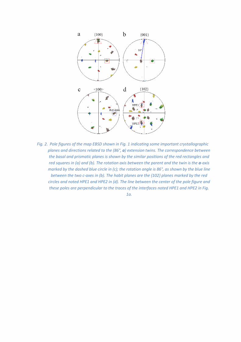
Fig. 2. Pole figures of the map EBSD shown in Fig. 1 indicating some important crystallographic
planes and directions related to the (86°, a) extension twins. The correspondence between
the basal and prismatic planes is shown by the similar positions of the red rectangles and
red squares in (a) and (b). The rotation axis between the parent and the twin is the a-axis
marked by the dashed blue circle in (c); the rotation angle is 86°, as shown by the blue line
between the two c-axes in (b). The habit planes are the {102} planes marked by the red
circles and noted HPE1 and HPE2 in (d). The line between the center of the pole figure and
these poles are perpendicular to the traces of the interfaces noted HPE1 and HPE2 in Fig.
1a.
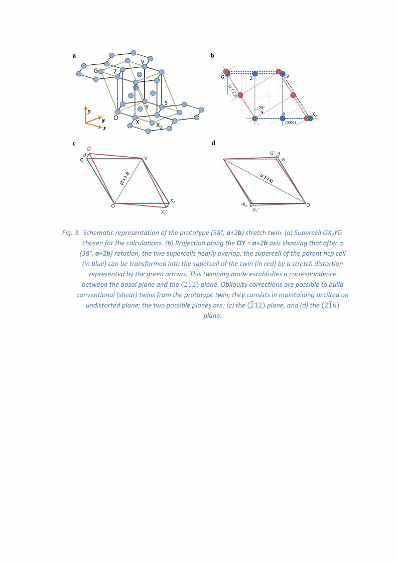
Fig. 3. Schematic representation of the prototype (58°, a+2b) stretch twin. (a) Supercell OX2YG
chosen for the calculations. (b) Projection along the OY = a+2b axis showing that after a
(58°, a+2b) rotation, the two supercells nearly overlap; the supercell of the parent hcp cell
(in blue) can be transformed into the supercell of the twin (in red) by a stretch distortion
represented by the green arrows. This twinning mode establishes a correspondence
between the basal plane and the (212) plane. Obliquity corrections are possible to build
conventional (shear) twins from the prototype twin; they consists in maintaining untilted an
undistorted plane; the two possible planes are: (c) the (212) plane, and (d) the (216)
plane.

Fig. 4. Pole figures of the EBSD map shown in Fig. 1 indicating some important crystallographic
planes and directions related to the unconventional (58°, a+2b) green twin. The
correspondence between the basal plane and the {112} planes is shown by the similar
positions of the red rectangles and red squares in (b) and (c). The rotation axis between the
parent and the twin is the axis <120> marked by the dashed blue circle in (a); the rotation
angle is 58°, as shown by the blue line between the two c-axes in (b). The two undistorted
planes common to the twin and the parent crystal are the {112} and {116} planes marked by
the red circles in (c) and (d). None of these two planes agrees with the traces of the habit
planes of the green twin noted HP1 and HP2 in Fig. 1.

Fig. 5. Pole figures of the EBSD map revealing the unconventional character of the (58°, a+2b)
green twin. The trace of the green twins noted HP1 and HP2 in Fig. 1 are perpendicular to
the planes {212}p of the parent crystal marked by the red circles around the grey spots in (b),
and these planes are parallel to some of the {102}gr planes of the green twin marked by the
red circles around the green spots in (a). It can also be noticed that these {102} planes are
common planes of the green and yellow twins. The <201> pole figure in (c) shows that the
<201> directions noted DIR1 and DIR2 belonging to the {212} plane HP1 and HP2,
respectively, are common to the parent, green and yellow crystals.
Fig. 6. Atomic model of the (212)p (012)gr transformation. (a) (212)p plane of the parent crystal
drawn in the reference frame. (b) The same plane viewed edge-on; it is constituted of two
parallel layers of atoms, one with atoms of coordinates [u, v, w] positioned at the level l =
2u+v+2w = 0 (in blue), and the other one with atoms at the level l = 2u+v+2w = 1/3 (in light
grey). The displacements of the atoms of the layer l = 1/3 down to the lower layer l = 0 are
shown by the green curves arrows. (c) Plane (012)gr of the green twin constituted of only
one layer l = v+2w = 0 (in red), obtained after the atomic displacements and lattice
distortion.

Extended Data
Extended Data Fig.1. EBSD map of the magnesium single crystal cut on section B. (a) Map with
colors chosen according to those used for the different twin types in Fig. 1a. (b) Disorientation
histogram, with in (c) the rotation axes corresponding to the three peaks of the histogram plotted in
the fundamental sector of the hexagonal lattice.
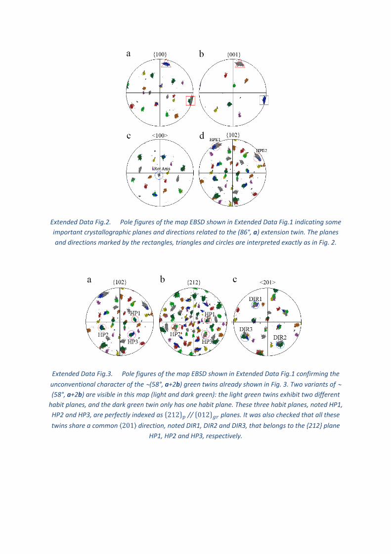
Extended Data Fig.2. Pole figures of the map EBSD shown in Extended Data Fig.1 indicating some
important crystallographic planes and directions related to the (86°, a) extension twin. The planes
and directions marked by the rectangles, triangles and circles are interpreted exactly as in Fig. 2.
Extended Data Fig.3. Pole figures of the map EBSD shown in Extended Data Fig.1 confirming the
unconventional character of the (58°, a+2b) green twins already shown in Fig. 3. Two variants of
(58°, a+2b) are visible in this map (light and dark green): the light green twins exhibit two different
habit planes, and the dark green twin only has one habit plane. These three habit planes, noted HP1,
HP2 and HP3, are perfectly indexed as {212}𝑝 // {012}𝑔𝑟 planes. It was also checked that all these
twins share a common ⟨201⟩ direction, noted DIR1, DIR2 and DIR3, that belongs to the {212} plane
HP1, HP2 and HP3, respectively.

Extended Data Fig.4. TEM image of an unconventional (58°, a+2b) twin. (a) Bright field image, (b)
selected area diffraction pattern along the [101]hex zone axis (ZA) of the twin, (c) selected area
diffraction pattern in the surrounding parent crystal with the same sample orientation as that of (b).
No secondary twins or special dislocation pile-ups were detected in the twin.

Supplementary Equations
1. Preliminary
1.1. Definition of the distortion, orientation and correspondence matrices
Deformation twinning is a lattice transformation under stress or strain from a parent crystal (p) to
the twinned crystal (t); this distortion restores the lattice in a new orientation. Mathematically, it can
be defined by a distortion matrix 𝐃𝑝→𝑡
. Any direction u is transformed after distortion into a new
direction 𝒖′ = 𝐃𝑝→𝑡𝒖. A plane g, considered as a vector of the reciprocal space, is transformed after
distortion into a new plane 𝒈′ = (𝐃𝑝→𝑡)∗𝒈 with (𝐃
𝑝→𝑡)∗= (𝐃
𝑝→𝑡)−T
where the symbol –T means
the inverse of the transpose.
It is often necessary for the calculation to switch from the crystallographic basis to an orthonormal
basis linked to this basis. In the case of an hexagonal phase, we call 𝐁ℎ𝑒𝑥 = (𝒂, 𝒃, 𝒄) the usual
hexagonal basis, and 𝐁𝑜𝑟𝑡ℎ𝑜 = (𝒙, 𝒚, 𝒛) the orthonormal basis linked to 𝐁ℎ𝑒𝑥 by the coordinate
transformation matrix 𝐇ℎ𝑒𝑥:
𝐇ℎ𝑒𝑥 = [𝐁𝑜𝑟𝑡ℎ𝑜 → 𝐁ℎ𝑒𝑥] = (
1 −1 2⁄ 0
0 √3 2⁄ 00 0 𝛾
)
(1)
where 𝛾 is the c/a packing ratio of the hexagonal phase. The matrix 𝐇ℎ𝑒𝑥 is commonly called
structure tensor in crystallography. It can be used to express the directions into the orthonormal
basis 𝐁𝑜𝑟𝑡ℎ𝑜. For planes, it is 𝐇ℎ𝑒𝑥∗ that should be used. We note O, the “zero” position that will be
left invariant by the distortion and we note X, Y and Z the atomic positions defined by the vectors OX
= a = [100]hex, OY = a + 2b = [120]hex and OZ = c = [001]hex. It can be checked with the matrix 𝐇ℎ𝑒𝑥
that OX = [100]ortho, OY = [0 √3 0]ortho and OZ = [0 0 ]ortho.
The vectors of the initial parent basis are transformed by the distortion into new vectors: 𝐚𝑝 → 𝐚′𝑝,
𝐛𝑝 → 𝐛′𝑝 and 𝐜𝑝 → 𝐜′𝑝. The distortion matrix expressed in the hexagonal basis 𝐃ℎ𝑒𝑥𝑝→𝑡
is the matrix
formed by the images 𝐚′𝑝, 𝐛′𝑝 and 𝐜′𝑝 expressed in 𝐁ℎ𝑒𝑥, i.e. 𝐃ℎ𝑒𝑥𝑝→𝑡
= [𝐁ℎ𝑒𝑥𝑝
→ 𝐁ℎ𝑒𝑥′𝑝] = 𝐁ℎ𝑒𝑥
′𝑝 with
𝐁ℎ𝑒𝑥𝑝
= (𝐚𝑝, 𝐛𝑝, 𝐜𝑝) and 𝐁ℎ𝑒𝑥′𝑝
= (𝐚′𝑝, 𝐛′𝑝, 𝐜′𝑝). In simple words, the distortion matrix is expressed by
writing in column the coordinates of 𝐚′𝑝, 𝐛′𝑝 and 𝐜′𝑝 in the basis 𝐁ℎ𝑒𝑥𝑝
. The crystallographic studies
on displacive phase transformations and mechanical twinning often consist in finding the distortion
matrices close to the identity matrix in order to minimize the atomic displacements.
If the distortion matrix is known in the basis 𝐁𝑜𝑟𝑡ℎ𝑜, and noted 𝐃𝑜𝑟𝑡ℎ𝑜𝑝→𝑡
, a formula of coordinate
transformation can be used to express it in the basis 𝐁ℎ𝑒𝑥 ; it is:
𝐃ℎ𝑒𝑥𝑝→𝑡
= 𝐇ℎ𝑒𝑥−1 𝐃𝑜𝑟𝑡ℎ𝑜
𝑝→𝑡 𝐇ℎ𝑒𝑥 (2)
with 𝐇ℎ𝑒𝑥 given by equation (1). Inversely, if the distortion matrix is found in 𝐁ℎ𝑒𝑥 and it can be
written in 𝐁𝑜𝑟𝑡ℎ𝑜 by the inverse formula:

𝐃𝑜𝑟𝑡ℎ𝑜𝑝→𝑡
= 𝐇ℎ𝑒𝑥 𝐃ℎ𝑒𝑥𝑝→𝑡 𝐇ℎ𝑒𝑥−1 (3)
The misorientation matrix is defined by the coordinate transformation matrix 𝐓ℎ𝑒𝑥𝑝→𝑡
. This matrix
allows the change of the coordinates of a fixed vector between the parent and twin bases. It is given
by the vectors forming the basis of the twin 𝐁ℎ𝑒𝑥𝑡 = (𝐚𝑡, 𝐛𝑡 , 𝐜𝑡) expressed in the parent hexagonal
basis, i.e. 𝐓ℎ𝑒𝑥𝑝→𝑡
= [𝐁ℎ𝑒𝑥𝑝
→ 𝐁ℎ𝑒𝑥𝑡 ]. Its reverse is just 𝐓ℎ𝑒𝑥
𝑡→𝑝= [𝐁ℎ𝑒𝑥
𝑡 → 𝐁ℎ𝑒𝑥𝑝].
The orientation of the twinned crystal is defined by the matrix 𝐓ℎ𝑒𝑥𝑝→𝑡
, but other equivalent matrices
could be chosen. The equivalent matrices are obtained by multiplying 𝐓ℎ𝑒𝑥𝑝→𝑡
by the matrices 𝒈𝒊 of
internal symmetries of the hexagonal phase, i.e. the matrices forming the point group of the hcp
phase 𝔾ℎ𝑐𝑝 .
{𝐓ℎ𝑒𝑥𝑝→𝑡} = {𝐓ℎ𝑒𝑥
𝑝→𝑡𝒈𝒊 , 𝒈𝒊 ∈ 𝔾
ℎ𝑐𝑝 } (4)
The matrix 𝐓ℎ𝑒𝑥𝑝→𝑡
is a coordinate transformation matrix between two hexagonal bases; it is thus a
rotation matrix. The rotation angle of a matrix 𝐓ℎ𝑒𝑥𝑝→𝑡
is given by its trace and the rotation axis is the
eigenvector associated with the unit eigenvalue. However, one must keep in mind that 𝐓ℎ𝑒𝑥𝑝→𝑡
is
expressed in a non-orthonormal basis, which implies that some usual equations related to rotations
do not hold. For example, the inverse of a rotation matrix equals its transposes only in orthonormal
basis. Using 𝐓𝑜𝑟𝑡ℎ𝑜𝑝→𝑡
= 𝐇ℎ𝑒𝑥𝐓ℎ𝑒𝑥𝑝→𝑡(𝐇ℎ𝑒𝑥)
−1 in the calculations allow avoiding possible errors.
In the set of equivalent matrices{𝐓ℎ𝑒𝑥𝑝→𝑡}, it is custom to choose the rotation with the lowest angle,
called “disorientation”. This choice has practical applications, but it remains arbitrary.
The correspondence matrix 𝐂ℎ𝑒𝑥𝑡→𝑝
gives the distortion images expressed in the twin basis of the
parent basis vectors, i.e. 𝐚′𝑝, 𝐛′𝑝 and 𝐜′𝑝. These images are obtained from the misorientation
matrix and the distortion matrix: (𝐚′𝑝, 𝐛′𝑝, 𝐜′𝑝)/𝐁ℎ𝑒𝑥𝑡 = 𝐓ℎ𝑒𝑥
𝑡→𝑝 (𝐚′𝑝, 𝐛′𝑝, 𝐜′𝑝)/𝐁ℎ𝑒𝑥
𝑝 = 𝐓ℎ𝑒𝑥𝑡→𝑝 𝐁ℎ𝑒𝑥′𝑝
=
𝐓ℎ𝑒𝑥𝑡→𝑝 𝐃ℎ𝑒𝑥𝑝→𝑡
. The correspondence matrix is thus:
𝐂ℎ𝑒𝑥𝑡→𝑝
= 𝐓ℎ𝑒𝑥𝑡→𝑝 𝐃ℎ𝑒𝑥𝑝→𝑡
(5)
The correspondence matrix is used to calculate in the twin basis the coordinates of the image by the
distortion of a vector written in the parent basis, i.e.
𝐱′/𝐁ℎ𝑒𝑥𝑝 = 𝐃ℎ𝑒𝑥
𝑝→𝑡 𝐱/𝐁ℎ𝑒𝑥
𝑝 → 𝐱′/𝐁ℎ𝑒𝑥𝑡 = 𝐂ℎ𝑒𝑥
𝑡→𝑝 𝐱/𝐁ℎ𝑒𝑥
𝑝 (6)
1.2. Construction of the distortion, misorientation and correspondence matrices
The crystallographic features of a twin model are determined by the choice of a supercell. This
supercell defines a sub-lattice of the hexagonal lattice; and it is actually this sub-lattice that is
linearly distorted by 𝐃𝑝→𝑡; the atoms inside the supercell do not follow the same trajectories as
those at the corners of the cells; they “shuffle”. The supercell is formed by three crystallographic
directions A, B, C defining a matrix
𝐁𝑠𝑢𝑝𝑒𝑟𝑝
= [𝐁ℎ𝑒𝑥𝑝
→ 𝐁𝑠𝑢𝑝𝑒𝑟𝑝
] = (𝐀, 𝐁, 𝐂)/𝐁ℎ𝑒𝑥𝑝 .

After distortion, the vectors of this basis are transformed into A’, B’, C’ that define a new basis
expressed in 𝐁ℎ𝑒𝑥𝑝
by the matrix 𝐁𝑠𝑢𝑝𝑒𝑟𝑝′
= (𝐀′, 𝐁′, 𝐂′)/𝐁ℎ𝑒𝑥𝑝 = [𝐁ℎ𝑒𝑥
𝑝→ 𝐁𝑠𝑢𝑝𝑒𝑟
𝑝′]. When the vectors
are expressed in the 𝐁ℎ𝑒𝑥𝑡 , it takes the form 𝐁𝑠𝑢𝑝𝑒𝑟
𝑡 = (𝐀′, 𝐁′, 𝐂′)/𝐁ℎ𝑒𝑥𝑡 = [𝐁ℎ𝑒𝑥
𝑡 → 𝐁𝑠𝑢𝑝𝑒𝑟𝑡 ].
As 𝐁𝑠𝑢𝑝𝑒𝑟𝑝′
and 𝐁𝑠𝑢𝑝𝑒𝑟𝑡 express the same vectors, we get
[𝐁𝑠𝑢𝑝𝑒𝑟𝑝′
→ 𝐁𝑠𝑢𝑝𝑒𝑟𝑡 ] = 𝐈 (7)
with I the identity matrix. Building a crystallographic model dedicated to a specific twin consists in
finding the appropriate vectors A, B, C of the supercell and finding how they are transformed into A’,
B’, C’. The three important matrices previously defined can be calculated from the supercell.
The distortion matrix is expressed in 𝐁𝑠𝑢𝑝𝑒𝑟𝑝
by
𝐃𝑠𝑢𝑝𝑒𝑟𝑝→𝑡
= [𝐁𝑠𝑢𝑝𝑒𝑟𝑝
→ 𝐁𝑠𝑢𝑝𝑒𝑟𝑝′
] = [𝐁𝑠𝑢𝑝𝑒𝑟𝑝
→ 𝐁ℎ𝑒𝑥𝑝][𝐁ℎ𝑒𝑥
𝑝→ 𝐁𝑠𝑢𝑝𝑒𝑟
𝑝′] = (𝐁𝑠𝑢𝑝𝑒𝑟
𝑝)−1𝐁𝑠𝑢𝑝𝑒𝑟𝑝′
As the distortion matrix is an active matrix; writing it in the basis 𝐁ℎ𝑒𝑥𝑝
leads to
𝐃ℎ𝑒𝑥𝑝→𝑡
= [𝐁ℎ𝑒𝑥𝑝
→ 𝐁𝑠𝑢𝑝𝑒𝑟𝑝
]. 𝐃𝑠𝑢𝑝𝑒𝑟𝑝→𝑡
. [𝐁𝑠𝑢𝑝𝑒𝑟𝑝
→ 𝐁ℎ𝑒𝑥𝑝] = 𝐁𝑠𝑢𝑝𝑒𝑟
𝑝(𝐁𝑠𝑢𝑝𝑒𝑟
𝑝)−1𝐁𝑠𝑢𝑝𝑒𝑟𝑝′
(𝐁𝑠𝑢𝑝𝑒𝑟𝑝
)−1 , i.e.
𝐃ℎ𝑒𝑥𝑝→𝑡
= 𝐁𝑠𝑢𝑝𝑒𝑟𝑝′
(𝐁𝑠𝑢𝑝𝑒𝑟𝑝
)−1
(8)
The misorientation matrix is 𝐓ℎ𝑒𝑥𝑝→𝑡
= [𝐁ℎ𝑒𝑥𝑝
→ 𝐁ℎ𝑒𝑥𝑡 ] = [𝐁ℎ𝑒𝑥
𝑝→ 𝐁𝑠𝑢𝑝𝑒𝑟
𝑡 ][𝐁𝑠𝑢𝑝𝑒𝑟𝑡 → 𝐁ℎ𝑒𝑥
𝑡 ] , i.e.
𝐓ℎ𝑒𝑥𝑝→𝑡
= 𝐁𝑠𝑢𝑝𝑒𝑟𝑝
(𝐁𝑠𝑢𝑝𝑒𝑟𝑡 )
−1 (9)
The correspondence matrix is 𝐂ℎ𝑒𝑥𝑡→𝑝
= [𝐁ℎ𝑒𝑥𝑡 → 𝐁ℎ𝑒𝑥
𝑝′] = [𝐁ℎ𝑒𝑥
𝑡 → 𝐁ℎ𝑒𝑥𝑝][𝐁ℎ𝑒𝑥
𝑝→ 𝐁ℎ𝑒𝑥
𝑝′] , i.e.
𝐂ℎ𝑒𝑥𝑡→𝑝
= 𝐓ℎ𝑒𝑥𝑡→𝑝 𝐃ℎ𝑒𝑥𝑝→𝑡
, as found in equation (5). It can also be decomposed into
𝐂ℎ𝑒𝑥𝑡→𝑝
= [𝐁ℎ𝑒𝑥𝑡 → 𝐁𝑠𝑢𝑝𝑒𝑟
𝑡 ][𝐁𝑠𝑢𝑝𝑒𝑟𝑡 → 𝐁ℎ𝑒𝑥
𝑝′] = [𝐁ℎ𝑒𝑥
𝑡 → 𝐁𝑠𝑢𝑝𝑒𝑟𝑡 ][𝐁𝑠𝑢𝑝𝑒𝑟
𝑡 → 𝐁𝑠𝑢𝑝𝑒𝑟𝑝′
] [𝐁𝑠𝑢𝑝𝑒𝑟𝑝′
→ 𝐁ℎ𝑒𝑥𝑝′] .
As the coordinates of the supercell are not changed by the distortion [𝐁ℎ𝑒𝑥𝑝′
→ 𝐁𝑠𝑢𝑝𝑒𝑟𝑝′
] =
[𝐁ℎ𝑒𝑥𝑝
→ 𝐁𝑠𝑢𝑝𝑒𝑟𝑝
] = 𝐁𝑠𝑢𝑝𝑒𝑟𝑝
, and by using (7), we get
𝐂ℎ𝑒𝑥𝑡→𝑝
= 𝐁𝑠𝑢𝑝𝑒𝑟𝑡 (𝐁𝑠𝑢𝑝𝑒𝑟
𝑝)−1
(10)
As the matrices 𝐁𝑠𝑢𝑝𝑒𝑟𝑝
and 𝐁𝑠𝑢𝑝𝑒𝑟𝑡 are constituted by the crystallographic directions forming the
supercell, their values are integers. As the inverse of an integer matrix is a rational matrix, the
correspondence matrix is a rational matrix.

1.3. Obliquity correction
It is usual in the crystallographic models of ferroelectrics to introduce an obliquity correction. This is
a rotation with a small angle (few degrees) that is composed with a stretch distortion matrix in order
to transform it into a simple shear matrix. An obliquity correction can be introduced to correct a
small tilt on a plane and/or an small rotation of a direction. Here we need to introduce a general
obliquity correction function 𝐎𝐛𝐥(𝒈, 𝒈′, 𝒖, 𝒖′). This function gives the rotation matrix noted Obl
such that 𝐎𝐛𝐥(𝒈) = 𝒈′ and (𝒖) = 𝒖′ . Let us consider a direction u and a plane g expressed in the
hexagonal basis. Expressed in the orthonormal basis 𝐁𝑜𝑟𝑡ℎ𝑜 they are 𝒖𝒐 = 𝐇ℎ𝑒𝑥𝒖 and 𝒈𝒐 = 𝐇ℎ𝑒𝑥∗ 𝒈.
In this basis the plane 𝒈 has the same coordinates as its normal direction 𝒏𝒐. A third direction
defined by 𝒍𝟎 = 𝒏𝒐⋀ 𝒖𝒐 allows building another orthonormal basis 𝐁(𝐠, 𝒖) = (𝒖𝒐
‖𝒖𝒐‖,𝒏𝒐
‖𝒏𝒐‖,𝒍𝟎
‖𝒍𝟎‖). We
build the orthonormal bases 𝐁(𝒈, 𝒖) and 𝐁(𝒈′, 𝒖′). The obliquity rotation is
𝐎𝐛𝐥(𝒈, 𝒈′, 𝒖, 𝒖′) = 𝐁(𝒈′, 𝒖′)(𝐁(𝒈, 𝒖))−𝟏
(11)
It is a rotation matrix expressed in the orthonormal basis 𝐁𝑜𝑟𝑡ℎ𝑜 that transforms 𝐁(𝒈, 𝒖) into
𝐁(𝒈′, 𝒖′). This rotation should be compensated by its inverse in order to put in coincidence the
plane 𝒈 with the plane 𝒈′, and the direction 𝒖 with the direction 𝒖′ .
1.4. Definition of unconventional twinning
We call conventional twin a twin whose lattice distortion is expressed by a simple shear matrix. The
habit plane of these twins is the shear plane, which is also the plane maintained fully invariant by the
shear distortion. This means that for two non-collinear directions u and v of the plane g, i.e. such
that g.u = g.v = 0, are invariant by the distortion: 𝐃𝑝→𝑡𝒖 = 𝒖 and 𝐃
𝑝→𝑡𝒗 = 𝒗. This implies that the
dimension of the space formed by the kernel of 𝐃𝑝→𝑡
− 𝐈 is such that
Dim(Ker(𝐃𝑝→𝑡
− 𝐈)) = 2 (12)
If the plane g is invariant, it is untilted. Therefore, a consequence of the existence of an invariant
plane is
𝒈′ = (𝐃𝑝→𝑡)∗𝒈 = 𝒈. (13)
which means that 𝒈 is an eigenvector of (𝐃𝑝→𝑡)∗.
It should be noted that (12)(13), but the reciprocal is not always true.
By noting the plane 𝒈 by its Miller indices 𝒈 = (h,k,l), and considering that the interplanar distance
𝑑ℎ𝑘𝑙 =1
‖𝒈‖, we get
1
= 𝑑′ℎ𝑘𝑙𝑑ℎ𝑘𝑙
(14)
As the plane is invariant, the volume change is completely given by 1/. If =1, there is no volume
change, the shear is called “simple shear”. In the more general case, the shear is sometimes called

“invariant plane strain” (IPS) and not “shear” in order to distinguish it from pure shear (stretch). To
our knowledge, all the deformation twins reported in literature till now are simple shear.
In the manuscript, we call unconventional twin a twin defined by a distortion matrix for which a
plane is untilted, but not invariant. Mathematically it means that the distortion matrix checks
equation (13) but not equation (12). The untilted plane is transformed into a plane that is not
equivalent to the initial one by any of the crystal symmetries; some of the directions contained in
the plane are modified in length and/or angle. To our knowledge, unconventional twinning has
never been reported till now.
2. Unconventional (𝟐𝟏𝟐) → (𝟎𝟏𝟐) twinning mode built by obliquity
correction of the (58°, a + 2b) prototype stretch twin
2.1. The (58°, a + 2b) prototype stretch twin
The calculations were performed with Mathematica (see Supplementary Data Part A). This twin
mode is also largely described in a separate paper28; only its main characteristics are recalled here.
Let us use the letter “p” for the parent crystal, and “gr” for the (58°, a+2b) twins colored in “green”
in the EBSD maps. The 𝑝 → 𝑔𝑟 distortion is associated with the transformation 𝐎𝐗2 → 𝐎𝐗′2,
𝐎𝐘 → 𝐎𝐘′, 𝐎𝐆 → 𝐎𝐆′ such that
𝐎𝐗2 = [200]𝑝 is parallel to the twin vector 𝐎𝐗2′ = [101]𝑔𝑟
OY is invariant, 𝐎𝐘 = [120]𝑝 is equal to 𝐎𝐘′ = [120]𝑔𝑟
𝐎𝐆 = [101]𝑝 is parallel to the twin vector 𝐎𝐆′ = [200]𝑔𝑟
The vectors are here expressed by their hexagonal coordinates. The distortion matrix is thus28
𝐅ℎ𝑒𝑥𝑝→𝑔𝑟
=
(
√1+𝛾2
2
2−√1+𝛾2
4
𝛾2−3
2√1+𝛾2
0 1 0
0 02
√1+𝛾2 )
(15)
The values of the principal strains can be calculated in the cases of ideal hard-sphere packing and
pure magnesium; they are (-4.2%, 0, +4.4%) or (-4.6%, 0, +4.8%), respectively.
The correspondence matrix is calculated by considering the vectors 𝐎𝐗2, 𝐎𝐘, and 𝐎𝐆, and the
vectors 𝐎𝐗2′, 𝐎𝐘′, and 𝐎𝐆′, in their respective hexagonal bases , i.e. by using the supercell
(𝐎𝐗2, 𝐎𝐘, 𝐎𝐆):
𝐁𝑠𝑢𝑝𝑒𝑟𝑝
= (2 1 −10 2 00 0 1
) and 𝐁𝑠𝑢𝑝𝑒𝑟𝑔𝑟
= (1 1 −20 2 01 0 0
) (16)
The expressions of the correspondence matrix in the direct and reciprocal space are:

𝐂ℎ𝑒𝑥𝑔𝑟→𝑝
= 𝐁𝑠𝑢𝑝𝑒𝑟𝑔𝑟
. (𝐁𝑠𝑢𝑝𝑒𝑟𝑝
)−1= (
1
2
1
4−3
2
0 1 01
2−1
4
1
2
) , and
(𝐂ℎ𝑒𝑥𝑔𝑟→𝑝
)∗= (𝐂ℎ𝑒𝑥
𝑔𝑟→𝑝)−𝑇=
(
1
20 −
1
21
41
1
43
20
1
2 )
(17)
The misorientation matrix is given by equation (5):
𝐓ℎ𝑒𝑥𝑝→𝑡
= 𝐃ℎ𝑒𝑥𝑝→𝑡( 𝐂ℎ𝑒𝑥
𝑡→𝑝)−1=
(
1
√1 + 𝛾20
𝛾
√1 + 𝛾2
0 1 0
−𝛾
√1 + 𝛾20
1
√1 + 𝛾2)
(18)
which is a rotation of angle 𝐴𝑟𝑐𝐶𝑜𝑠 (1
√1+𝛾2) = 𝐴𝑟𝑐𝑇𝑎𝑛(𝛾), that is equal to 58.5° for hard-sphere
packing and 58.4° for magnesium.
Some correspondences between some planes and directions of the parent and its twins calculated
from the correspondence matrices in equation (17) are interesting to interpret the EBSD map. They
are given in Table 1.
Parent → Twin
Planes
(𝟐𝟏𝟐) {𝟏𝟐��𝟐} → (𝟎𝟐𝟒) {𝟎𝟐��𝟒}
(004) {0004} → (212) {2112}
Directions
[𝟎��𝟏] 𝟏
𝟑⟨𝟐𝟐��𝟑⟩ → [����𝟏]
𝟏
𝟑⟨𝟐𝟐��𝟑⟩
[200] 1
3⟨2240⟩ → [101]
1
3⟨1123⟩
[101] 1
3⟨1123⟩ → [200]
1
3⟨2240⟩
[120] ⟨0110⟩ → [120] ⟨0110⟩
Supplementary Table 1. Correspondence between some planes and between some directions
established by the (58°,a) stretch twin. The families of their equivalent directions/planes are
indicated by using the four-index Miller-Bravais notations. The plane g0 = (212)𝑝 and the direction u0
= [021]𝑝 of the parent crystal (in bold) will be used to build the model of the green twins.
From this table, we tried two different approaches to build a model that could explain the green
twins observed experimental EBSD maps. The first approach was the most intuitive one; it is based
on the fact that the direction 𝐎𝐘 = [120]𝑝 is invariant in the stretch twin model (see Supplementary
Table 1). However, after many attempts, this way was given up because all the habit planes we could

predict contain the OY direction, which is not in agreement with the observations. A dissymmetry
should be introduced in the system. The second approach was less intuitive; but it was revealed to
fit perfectly with the observations, even for small details that were not noticed at the beginning. It is
based on the correspondence between the (212)𝑝 and (012)𝑔𝑟 planes, and between the [021]𝑝
and [221]𝑔𝑟 directions (Supplementary Table 1). The model, described in the next section,
introduces an obliquity correction such that the plane 𝒈0 = (212)𝑝 becomes untilted and the
direction 𝒖0 = [021]𝑝 invariant.
2.2. Unconventional twin derived from the (58°, a + 2b) stretch twin prototype
The calculations were performed with Mathematica (see Supplementary Data Part B).
The EBSD map shows that the habit plane of the green twin is not invariant; it is the plane
(212)𝑝 transformed into the plane (012)𝑔𝑟. These two planes are not equivalent. The modification
of this plane comes from the transformation of the directions it contains, i.e. [101]𝑝 is transformed
into [200]𝑔𝑟, and [021]𝑝 is transformed into [221]𝑔𝑟. The transformation of the direction [101]𝑝
occurs by a stretch of 2
√1+𝛾2≈ 1.04. There is no stretch for the [021]𝑝 direction because it is
equivalent to [221]𝑔𝑟. In addition, the angle formed by the pairs p = ([101]𝑝, [021]𝑝) =
𝐴𝑟𝑐𝐶𝑜𝑠(𝛾2−1
√4+5𝛾2+𝛾4) 70.56° is slightly reduced to become that the angle between the pair t =
([021]𝑔𝑟 , [221]𝑔𝑟) = 𝐴𝑟𝑐𝐶𝑜𝑠(1
√4+𝛾2) 67.15°. The stretch of the [101]𝑝 direction (+4%) and the
angular distortion of the plane (-3°) are quite small. We noticed that the planar transformation
(212)𝑝 (012)𝑔𝑟 can be explained by the displacements of the atoms located in the upper layer l =
1/3 of the plane (212)𝑝 as described in Fig.6.
Even if the direction 𝒖𝟎 = [021]𝑝 is not stretched, the prototype twin induces a slight rotation of
angle ξ𝑢 of this direction. This is this rotation that should be compensated in order to build the
model. The rotation angle ξ𝑢 can be calculated by working in the orthonormal basis; it is the angle
between 𝐇ℎ𝑒𝑥𝒖𝟎 and 𝐅𝑜𝑟𝑡ℎ𝑜𝑝→𝑡
. 𝐇ℎ𝑒𝑥 𝒖𝟎, with 𝐅𝑜𝑟𝑡ℎ𝑜𝑝→𝑡
the inverse of the transpose of the matrix (15).
The calculations show that
ξ𝑢 = 𝐴𝑟𝑐𝐶𝑜𝑠 (−1 + 3𝛾2 + 3√1 + 𝛾2
√1 + 𝛾2(4 + 𝛾2))
(19)
For a hard-sphere packing ratio = √8
3 , the obliquity is ξ𝑢 = 𝐴𝑟𝑐𝐶𝑜𝑠 (
99+21√33
220) ≈ 3.29°.
The stretch prototype twin also induces a rotation of the plane 𝒈𝟎 = (212)𝑝. The rotation angle ξ𝑔
is the angle between 𝐇ℎ𝑒𝑥∗ 𝒈𝟎 and (𝐅𝑜𝑟𝑡ℎ𝑜
𝑝→𝑡)∗𝐇ℎ𝑒𝑥∗ 𝒈𝟎, with (𝐅𝑜𝑟𝑡ℎ𝑜
𝑝→𝑡)∗ the inverse of the transpose of
the matrix (15). The calculations show that
ξ𝑔 = 𝐴𝑟𝑐𝐶𝑜𝑠 (3 + 𝛾2(3 + 2√1 + 𝛾2)
√(1 + 𝛾2)(3 + 𝛾2)(3 + 7𝛾2))
(20)
For a hard-sphere packing ratio = √8
3 , the obliquity is ξ𝑔 = 𝐴𝑟𝑐𝐶𝑜𝑠 (
16+3√33
√1105) ≈ 1.24°.
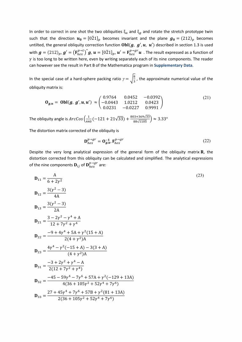
In order to correct in one shot the two obliquities ξ𝑢 and ξ𝑔 and rotate the stretch prototype twin
such that the direction 𝒖𝟎 = [021]𝑝 becomes invariant and the plane 𝒈𝟎 = (212)𝑝 becomes
untilted, the general obliquity correction function 𝐎𝐛𝐥(𝒈, 𝒈′, 𝒖, 𝒖′) described in section 1.3 is used
with 𝒈 = (212)𝑝, 𝒈′ = (𝐅ℎ𝑒𝑥𝑝→𝑡)∗𝒈, 𝒖 = [021]𝑝, 𝒖′ = 𝐅ℎ𝑒𝑥
𝑝→𝑔𝑟𝒖 . The result expressed as a function of
𝛾 is too long to be written here, even by writing separately each of its nine components. The reader
can however see the result in Part B of the Mathematica program in Supplementary Data.
In the special case of a hard-sphere packing ratio = √8
3 , the approximate numerical value of the
obliquity matrix is:
𝐎𝒈,𝒖 = 𝐎𝐛𝐥(𝒈, 𝒈′, 𝒖, 𝒖′) ≈ (
0.9764 0.0452 −0.0392−0.0443 1.0212 0.04230.0231 −0.0227 0.9991
) (21)
The obliquity angle is 𝐴𝑟𝑐𝐶𝑜𝑠 (1
440(−121 + 21√33) +
803+369√33
88√1105) ≈ 3.33°
The distortion matrix corrected of the obliquity is
𝐃ℎ𝑒𝑥𝑝→𝑔𝑟
= 𝐎𝒈,𝒖−𝟏 . 𝐅ℎ𝑒𝑥
𝑝→𝑔𝑟 (22)
Despite the very long analytical expression of the general form of the obliquity matrix 𝐑, the
distortion corrected from this obliquity can be calculated and simplified. The analytical expressions
of the nine components 𝐃𝑖𝑗 of 𝐃ℎ𝑒𝑥𝑝→𝑔𝑟
are:
𝐃11 =A
6 + 2𝛾2
𝐃12 =3(𝛾2 − 3)
4A
𝐃13 =3(𝛾2 − 3)
2A
𝐃21 =3 − 2𝛾2 − 𝛾4 + A
12 + 7𝛾2 + 𝛾4
𝐃22 =−9 + 4𝛾4 + 5A + 𝛾2(15 + A)
2(4 + 𝛾2)A
𝐃23 =4𝛾4 − 𝛾2(−15 + A) − 3(3 + A)
(4 + 𝛾2)A
𝐃31 =−3 + 2𝛾2 + 𝛾4 − A
2(12 + 7𝛾2 + 𝛾4)
𝐃32 =−45 − 59𝛾4 − 7𝛾6 + 57A + 𝛾2(−129 + 13A)
4(36 + 105𝛾2 + 52𝛾4 + 7𝛾6)
𝐃33 =27 + 45𝛾4 + 7𝛾6 + 57B + 𝛾2(81 + 13A)
2(36 + 105𝛾2 + 52𝛾4 + 7𝛾6)
(23)

with 𝐴 = √(3 + 𝛾2)(3 + 7𝛾2)
It is checked that this distortion matrix 𝐃ℎ𝑒𝑥𝑝→𝑔𝑟
maintains invariant the direction 𝒖𝟎 = [021]𝑝 and
that (𝐃ℎ𝑒𝑥𝑝→𝑡)∗ maintains untilted the plane 𝒈𝟎 = (212)𝑝 .
For the ideal hard-sphere packing ratio, the distortion matrix takes the value
𝐃ℎ𝑒𝑥𝑝→𝑔𝑟
=
(
√6517
2−
3
4√1105−
3
2√1105
−1
4+3√1385
4
23
40+
107
8√1105−17
20+
107
4√1105
1
8−3√1385
8−23
80+33√
5221
16
17
40+33√
5221
8 )
≈ (0.9777 −0.0226 −0.04510.0433 0.9774 −0.0453−0.0217 0.0227 1.0455
)
(24)
As 𝐃ℎ𝑒𝑥𝑝→𝑔𝑟
differs from 𝐅ℎ𝑒𝑥𝑝→𝑔𝑟
only by the obliquity correction, the correspondence matrix given by
equation (17) is not affected. The distortion 𝐃ℎ𝑒𝑥𝑝→𝑔𝑟
is unconventional as the untilted plane (212)𝑝,
which is also the habit plane of the green twin, is not fully invariant but transformed into the plane
(012)𝑔𝑟. The modes of plasticity required to accommodate this deformation are not the subject of
the paper, but it is hoped that deeper TEM investigations and molecular dynamics simulations can
bring important elements of responses.
We have seen in section 2.1 that the rotation matrix 𝐓ℎ𝑒𝑥𝑝→𝑔𝑟
between the parent and the green twin
associated with the stretch distortion 𝐅ℎ𝑒𝑥𝑝→𝑔𝑟
is a rotation of axis OY = [120]hex and of angle
𝐹 = 𝐴𝑟𝑐𝐶𝑜𝑠(1
√1+𝛾2), that is 58.5° for hard-sphere packing, 58.4° for magnesium. Now, if instead of
the stretch prototype 𝐅ℎ𝑒𝑥𝑝→𝑔𝑟
, the distortion 𝐃ℎ𝑒𝑥𝑝→𝑔𝑟
applies, the orientation of the twinned crystal is
slightly modified. The new expression of orientation matrix 𝐓ℎ𝑒𝑥𝑝→𝑔𝑟
between the twin and the parent
is obtained by using the distortion matrix and the correspondence matrix in equation (5); it is
calculated in part B of Supplementary Data:
𝐓ℎ𝑒𝑥𝑝→𝑔𝑟
=
(
√
3 + 𝛾2
3 + 7𝛾2−3 + 2𝛾2
A
6𝛾2
A
2(3 − 𝛾2(2 + 𝛾2) + 𝐴)
(4 + 𝛾2)A
−6 + 13𝛾2 + 3𝛾4 + 2A
(4 + 𝛾2)A
2𝛾2(9 + 𝛾2 − A)
(4 + 𝛾2)A
18
3 + 7𝛾2 − 5A
9(12 + 𝛾2)
9 + 7𝛾4 + 21A+ 4𝛾2(6 + A)
24𝛾4 + 7𝛾6 + 12A + 𝛾2(9 − 2𝐴)
(3 + 7𝛾2)(12 + 7𝛾2 + 𝛾4) )
(25)
with 𝐴 = √(3 + 𝛾2)(3 + 7𝛾2)
The rotation angle is

𝐷 = 𝐴𝑟𝑐𝐶𝑜𝑠 (9 + 9𝛾2 + 2𝛾4 − A
(4 + 𝛾2)A)
(26)
The rotation axis is a complex form of the packing ratio 𝛾; it slightly deviates from the axis OY =
[120]hex. In the case of the ideal hard-sphere packing ratio, the rotation angle is
𝐷 = 𝐴𝑟𝑐𝐶𝑜𝑠 (−3
20+√85
13
4) ≈ 60.71° , and the axis is [1, 2,
3
(31+√1105)]ℎ𝑒𝑥
≈ [1, 2, 0.047]ℎ𝑒𝑥. For
magnesium the angle is 𝐷 ≈ 60.76°, and the axis is ≈ [1, 2, 0.051]ℎ𝑒𝑥. Consequently, a careful
examination of the rotation angle of the misorientation between the twin and its parent permits to
know whether this twin directly comes from the prototype stretch distortion 𝐅ℎ𝑒𝑥𝑝→𝑔𝑟
or from its
derived obliquity-corrected form, i.e. 𝐃ℎ𝑒𝑥𝑝→𝑔𝑟
. In the former case the misorientation angle is close
58° and in the latter case is close to 61°. Both forms exist in the EBSD map of Fig.1.
The other method to distinguish the twin generated by distortion 𝐅ℎ𝑒𝑥𝑝→𝑔𝑟
from the one generated by
𝐃ℎ𝑒𝑥𝑝→𝑔𝑟
consists in considering the ⟨201⟩ directions. All are rotated by the distortion 𝐅ℎ𝑒𝑥𝑝→𝑔𝑟
whereas
the distortion matrix 𝐃ℎ𝑒𝑥𝑝→𝑔𝑟
maintains the direction 𝒖𝟎 = [021]𝑝 invariant.
A rotation equivalent to 𝐓ℎ𝑒𝑥𝑝→𝑔𝑟
that has 𝒖𝟎 for rotation axis is found by using a 6-fold rotation
symmetry. In the basis 𝐁ℎ𝑒𝑥 , and noted by its Seitz symbol, this symmetry is
𝟔001− = (
0 1 0−1 1 00 0 1
) (27)
The equivalent rotation between the twin and the parent crystal is 𝐓ℎ𝑒𝑥𝑝→𝑔𝑟
. 𝟔001− . This rotation matrix
is explicitly written in PartB of Supplementary Data. The rotation angle is
𝐷 = 𝐴𝑟𝑐𝐶𝑜𝑠 (6 − 𝛾2
2A)
(28)
In the case of hard-sphere packing, this angle is 𝐷 = 𝐴𝑟𝑐𝐶𝑜𝑠 (√5
221) ≈ 81.35° . It was checked that
the rotation axis is indeed 𝒖𝟎 = [021]𝑝 , independently of the packing ratio 𝛾.The commercial EBSD
programs do not give all the equivalent rotations but only the disorientation, i.e. the rotation that
among all the equivalent rotations has the lowest angle. The present example shows that this choice
is sometimes not well adapted, as the rotation axis of 𝐓ℎ𝑒𝑥𝑝→𝑔𝑟
is complex, even if close to [120],
whereas that of 𝐓ℎ𝑒𝑥𝑝→𝑔𝑟
. 𝟔001− is simply a rotation around the [021] direction.
3. Unconventional (𝟎𝟏𝟐) → (𝟐𝟏𝟐) twinning mode by obliquity
correction of the (86°, a) twin
The experimental EBSD maps show that the extension “yellow” twins are often co-formed with the
“green” twins and constitute green-yellow “stripes” as that in the green rectangle of Fig.1a. In the
EBSD map acquired in the cross-section B, the yellow twins can also appear orange or red, as shown
in the Extended Data Fig.1. The striking point is that these the “yellow” twins are conventional twins

of the parent “grey” crystal: their habit plane is the plane (212)𝑝, and this plane is common to both
the parent and “yellow” crystal. The misorientation between the “yellow” twins and the parent
“grey” crystal experimentally measured from the EBSD maps is a rotation of 48° around an axis close
to a ⟨241⟩ direction, as shown in Fig.1b and c. To the best of our knowledge this twin has never been
reported or predicted; which means that, even if conventional, there is not yet crystallographic
model for it. In order to build such a model, additional information is required. We noticed that the
misorientation between the yellow twins and the green twins is close to (86°, a), with an interface
plane close to {102}, which means that the yellow and green twins are linked by an kind of
extension twin relation, or a twinning relation close to that one.
The crystallographic model of (86°, a) extension twinning in hcp metals was proposed by correcting
the obliquity of a (90°, a) prototype stretch twin to maintain a plane {102} untilted21. The
correspondence matrix written in the reciprocal space shows that among the five other equivalent
{102} planes, one is also transformed into another {102} plane (by conjugation), and the four other
ones are transformed into {212} planes. Some of these four {102} planes transformed into {212}
planes are only slightly tilted during the extension twinning. Thus, it is possible, by adding an
obliquity correction to a conventional extension twin, to change the conventional extension twin
into an unconventional twin that transforms a {102} plane into a {212} plane without tilt. The green
twin transforms a {212}𝑝 plane into a {102}𝑔𝑟 plane, and the yellow twin would transform back this
{102}𝑔𝑟 plane into a {212}𝑝 plane, such that the yellow twin would leave invariant the {212}𝑝 plane
of the parent crystal, i.e. {212}𝑝 = {212}𝑦𝑒, as observed in the EBSD maps. Before detailing the
obliquity correction that will be applied to the conventional extension twin, let us determine the
appropriate reference frame that should be used to express the extension twinning distortion matrix
in order to be composed with the green twin.
3.1. The conventional (86°, a) twin in an adequate basis
The calculations were performed with Mathematica (see Supplementary Data Part C).
In order to build the unconventional yellow twin derived from a conventional (86°, a) extension twin,
we have to quickly recall some the crystallographic details of this twin. The (86°, a) extension twin
described in the paper21 is an extension twin on the plane (012)𝑝. This twin was shown to derive
from a stretch prototype, called (90°, a) twin. Most of the calculations21 were done by assuming an
ideal hard-sphere packing ratio in order to determine the continuous form of the distortion. The
calculations related to the general case depending on were not explicitly detailed. Let us present
them now. The distortion matrix associated with the (90°, a) twin is21
𝐔ℎ𝑒𝑥𝑝→𝑡
= (
1 0 0
0𝛾
√30
0 0√3
𝛾
)
(29)
This (90°, a) stretch prototype twin induces a rotation of the plane 𝒈 = (012)𝑝 around the axis
[100]𝑝. This rotation 𝐑𝒈 has for rotation angle ξ𝑔 that can be calculated by working in the
orthonormal basis; it is the angle between 𝐇ℎ𝑒𝑥∗ 𝒈 and (𝐔𝑜𝑟𝑡ℎ𝑜
𝑝→𝑡)∗. 𝐇ℎ𝑒𝑥
∗ 𝒈, with (𝐔𝑜𝑟𝑡ℎ𝑜𝑝→𝑡
)∗ the inverse
of the transpose of the matrix (29). The calculations computed in Part C of Supplementary Data
show that

ξ𝑔 = 𝐴𝑟𝑐𝐶𝑜𝑠 (2√3𝛾
3 + 𝛾2)
(30)
After the obliquity correction, the distortion matrix becomes
𝐄ℎ𝑒𝑥𝑝→𝑡
= 𝐑𝒈−𝟏. 𝐔ℎ𝑒𝑥
𝑝→𝑡=
(
1 −3−𝛾2
2(3+𝛾2)
3−𝛾2
3+𝛾2
02𝛾2
3+𝛾22(3−𝛾2)
3+𝛾2
0 −3−𝛾2
2(3+𝛾2)
6
3+𝛾2 )
(31)
For the ideal hard-sphere packing ratio, the obliquity is ξ𝑔 = 𝐴𝑟𝑐𝐶𝑜𝑠 (12√2
17) ≈ 3.37° , and the
obliquity-corrected distortion matrix becomes
𝐄ℎ𝑒𝑥𝑝→𝑡
=
(
1 −
1
34
1
17
016
17
2
17
0 −1
34
18
17)
(32)
The distortion matrix (32) generates the conventional (86°, a) twin for which the invariant plane is
(012)𝑝. In order to continue working with coherent coordinates in the system formed by the
“green”, “yellow” and “grey” crystals, we need to use an extension twin such that, once combined
with the green twin distortion (23), it yields a conventional twin on the (212)𝑝 plane. A hexagonal
symmetry is thus introduced; its choice will be justified a posteriori by the internal coherency of the
calculations and by the perfect agreement with the experimental EBSD observations. This internal
symmetry noted by its Seitz symbol is
𝟐110 = (0 1 01 0 00 0 −1
) (33)
It allows establishing the distortion matrix of the (102)𝑝 extension twin from that of the (012)𝑝
extension twin given in equation (32):
𝐄ℎ𝑒𝑥𝑔𝑟→𝑦𝑒
= (𝟐110)−1 𝐄ℎ𝑒𝑥
𝑝→𝑡𝟐110 =
(
2𝛾2
3+𝛾20 −
2(3−𝛾2)
3+𝛾2
−3−𝛾2
2(3+𝛾2)1 −
3−𝛾2
(3+𝛾2)
3−𝛾2
2(3+𝛾2)0
6
3+𝛾2 )
(34)
To be clearer, we have used in equation (34) a notation that specifies that the parent crystal is the
green grain and that the yellow grains are linked to it by an extension twin (even if not yet corrected
by the obliquity). Indeed, the parent index “p” is here “gr” and the twin index “t” is “gr”.
The correspondence matrices in the direct and reciprocal spaces are

𝐂ℎ𝑒𝑥𝑦𝑒→𝑔𝑟
= 𝐂ℎ𝑒𝑥𝑦𝑒→𝑔𝑟
𝟐110 = (
−1
21 1
0 0 21
20 0
)
and (𝐂ℎ𝑒𝑥𝑦𝑒→𝑔𝑟
)∗= (
0 1 0
0 −1
2
1
2
2 1 0
)
(35)
And the misorientation matrix is
𝐓ℎ𝑒𝑥𝑔𝑟→𝑦𝑒
= (𝟐110)−1 𝐓ℎ𝑒𝑥
𝑔𝑟→𝑦𝑒=
(
0 1 −
6
3 + 𝛾24𝛾2
3 + 𝛾2
1 −3
3 + 𝛾22𝛾2
3 + 𝛾2
03
3 + 𝛾2−1 +
6
3 + 𝛾2)
(36)
In the case of hard-sphere packing the distortion and orientation matrices take rational values:
𝐄ℎ𝑒𝑥𝑔𝑟→𝑦𝑒
=
(
16
170 −
2
17
−1
341 −
1
171
340
18
17 )
and 𝐓ℎ𝑒𝑥𝑔𝑟→𝑦𝑒
=
(
0 −
1
17
32
17
1 −9
17
16
17
09
17
1
17)
(37)
Now that the appropriate basis is found to express the conventional extension twin, the additional
obliquity correction required to get the planar distortion (012) → (212) without tilt can be
determined.
3.2. The unconventional twin derived from the (86°, a) twin prototype
The calculations were performed with Mathematica (see Supplementary Data Part D).
The extension twin (34) leaves invariant the plane (102)𝑔𝑟 and the direction [221]𝑔𝑟 , and it
transforms the plane (012)𝑔𝑟 into the plane (212)𝑦𝑒 by the correspondence matrix (35), but this
plane is tilted. Now, we will build by obliquity correction of the conventional extension twin (34) an
unconventional twin such that the plane (012)𝑔𝑟 is transformed into the plane (212)𝑦𝑒 without tilt,
and such that the direction [221]𝑔𝑟 becomes invariant. This twin, when composed with the
unconventional “green” twin, will give a conventional twin relatively to the “grey” parent crystal. In
order to determine the obliquity matrix, one could directly apply the general function (21), but we
noticed that correcting the obliquity of the plane 𝐠 = (012)𝑔𝑟 is sufficient to also correct the
obliquity of the direction [221]𝑔𝑟, as detailed as follows.
The tilt ξ𝑔 of the plane 𝐠 = (012)𝑔𝑟 by the conventional distortion matrix 𝐄ℎ𝑒𝑥𝑔𝑟→𝑦𝑒
can be calculated
by working in the orthonormal basis; it is the angle between 𝐇ℎ𝑒𝑥∗ 𝒈 and 𝐇ℎ𝑒𝑥
∗ (𝐄ℎ𝑒𝑥𝑔𝑟→𝑦𝑒
)∗𝒈, with
(𝐄ℎ𝑒𝑥𝑔𝑟→𝑦𝑒
)∗ the inverse of the transpose of the matrix (34):

ξ𝑔 = 𝐴𝑟𝑐𝐶𝑜𝑠 (18 + 27𝛾2 + 5𝛾4
2(3 + 𝛾2)A)
(38)
The obliquity rotation axis written in the hexagonal basis is
𝛚𝑔 =3 − 𝛾2
2√2(3 + 𝛾2)[2, 2, 1]
(39)
The rotation matrix required to compensate the tilt of the plane 𝐠0 = (012)𝑝 can thus be
calculated, but its analytical expression depending on the packing ratio is too large to fit the page
width. In the case of ideal 𝛾 ratio, the obliquity rotation angle is ξ𝑔 = 𝐴𝑟𝑐𝐶𝑜𝑠 (113
17√
5
221) ≈ 1.11°
and the rotation axis in the hexagonal basis is 𝛚𝑔 =1
17√2[2, 2, 1].
The obliquity-corrected distortion matrix is noted 𝐃ℎ𝑒𝑥𝑔𝑟→𝑦𝑒
. The analytical expressions of the nine
components 𝐃𝑖𝑗 of 𝐃ℎ𝑒𝑥𝑔𝑟→𝑦𝑒
depending on the stacking ratio calculated with Mathematica are:
𝐃11 =
2(−1 +√3 + 7𝛾2
3 + 𝛾2) + 𝛾2(2 + √
3 + 7𝛾2
3 + 𝛾2)
2(4 + 𝛾2)
𝐃12 =−6 − 3𝛾2 − 𝛾4 + 2A
(4 + 𝛾2)A
𝐃13 =11𝛾2 + 5𝛾4 − 6(1 + A)
(4 + 𝛾2)A
𝐃21 =−3 + 2𝛾2 + 𝛾4 − A
12 + 7𝛾2 + 𝛾4
𝐃22 =2(3 + 6𝛾2 + 𝛾4 + A)
(4 + 𝛾2)A
𝐃23 =2(3 + 5𝛾2 + 2𝛾4 − 3A)
(4 + 𝛾2)A
𝐃31 =3 − 2𝛾2 − 𝛾4 + A
24 + 14𝛾2 + 2𝛾4
𝐃32 =9 + 𝛾2 − A
(4 + 𝛾2)A
𝐃33 =3(9 + 7𝛾4 + 7A + 3𝛾2(8 + A))
(4 + 𝛾2)𝐴2
(40)
with 𝐴 = √(3 + 𝛾2)(3 + 7𝛾2)
In the case of ideal hard-sphere packing the distortion matrix takes the value:

𝐃ℎ𝑒𝑥𝑔𝑟→𝑦𝑒
=
(
1
4+7√1385
4
3
10−
19
2√1105−9
10+
53
2√1105
1
4−3√1385
4
3
10+
47
2√1105−9
10+11√
5221
2
−1
8+3√1385
8−3
20+
21
4√1105
9
20+
81
4√1105 )
≈ (0.9344 0.0142 −0.1028−0.0433 1.0069 −0.07270.0217 0.0079 1.0592
)
(41)
It can checked that 𝐃ℎ𝑒𝑥𝑔𝑟→𝑦𝑒
leaves invariant the direction 𝒖0 = [2, 2, 1]𝑔𝑟 and leaves untilted the
plane (012)𝑔𝑟
The orientation of the unconventional twin is given by the misorientation matrix between the
hexagonal bases. It is 𝐓ℎ𝑒𝑥𝑔𝑟→𝑦𝑒
= 𝐃ℎ𝑒𝑥𝑔𝑟→𝑦𝑒
(𝐂ℎ𝑒𝑥𝑦𝑒→𝑔𝑟
)−1
𝐓ℎ𝑒𝑥𝑔𝑟→𝑦𝑒
=
(
−6 − 3𝛾2 − 𝛾4 + 2𝐴
(4 + 𝛾2)𝐴
2(3 − 𝛾2(2 + 𝛾2) + 𝐴)
(4 + 𝛾2)𝐴−2𝛾2(7 + 3𝛾2 + 𝐴)
(4 + 𝛾2)𝐴
2(3 + 6𝛾2 + 𝛾4 + 𝐴)
(4 + 𝛾2)𝐴
−6 − 11𝛾2 − 3𝛾4 + 2𝐴
(4 + 𝛾2)𝐴−2𝛾2(−1 + 𝛾2 + 𝐴)
(4 + 𝛾2)𝐴
9 + 𝛾2 − A
(4 + 𝛾2)𝐴
18
3 + 7𝛾2 − 5𝐴
−12 + 𝛾2(−8 + 𝐴)
(4 + 𝛾2)𝐴 )
(42)
with 𝐴 = √(3 + 𝛾2)(3 + 7𝛾2)
This orientation matrix is fully equivalent by internal symmetry to the matrix 𝐓ℎ𝑒𝑥𝑔𝑟→𝑦𝑒
𝟐100 , which is
a rotation around the axis 𝒖0 = [2, 2, 1]𝑔𝑟 and of angle
𝐷 = 𝐴𝑟𝑐𝐶𝑜𝑠 (−3 − 2𝛾2
A)
(43)
In the case of hard-sphere packing, this angle is 𝐷 = 𝐴𝑟𝑐𝐶𝑜𝑠 (−5√5
221) ≈ 138.77° .

4. New conventional twin generated by the composition of the
unconventional twins derived from the (58°, a + 2b) and (86°,b) twin
prototypes.
The calculations were performed with Mathematica (see Supplementary Data Part E).
From the previous calculations and from the EBSD results, the crystallographic link between the
parent, green and yellow twins can be summarized as follows:
1. The green twin results from an unconventional (212)𝑝 → (012)𝑔𝑟 twinning of the parent
crystal. The correspondence, distortion and orientation matrices associated with this twin
mode are 𝐂ℎ𝑒𝑥𝑔𝑟→𝑝
, 𝐃ℎ𝑒𝑥𝑝→𝑔𝑟
and 𝐓ℎ𝑒𝑥𝑝→𝑔𝑟
given by equations (17), (23), and (25).
2. The yellow twins are linked to the green twins by an unconventional (012)𝑔𝑟 → (212)𝑦𝑒
twinning relationship that is an obliquity-corrected form of extension twinning. The
correspondence, distortion and orientation matrices associated with this twin mode are
𝐂ℎ𝑒𝑥𝑦𝑒→𝑔𝑟
, 𝐃ℎ𝑒𝑥𝑔𝑟→𝑦𝑒
and 𝐓ℎ𝑒𝑥𝑔𝑟→𝑦𝑒
given by equations (35), (40), and (42), respectively.
3. The yellow twins formed by the combination of the two unconventional twins, i.e.
𝒈𝟎 = (212)𝑝 → (012)𝑔𝑟 followed by (012)𝑔𝑟 → (212)𝑦𝑒 , appears as a conventional twin
relatively to the parent crystal because the plane 𝒈𝟎 = (212)𝑝 is restored, i.e. (212)𝑝 →
(212)𝑦𝑒.
4. The direction 𝒖𝟎 = [021]𝑝 is maintained invariant by the three twinning modes, only its
indexes are changed into equivalent ones: [021]𝑝 [221]𝑔𝑟[021]𝑦𝑒
Now, let us define the crystallographic properties of the conventional (parent yellow) twin. Its
correspondence, distortion and orientation matrices are determined by combination of the matrices
determined in the previous sections.
Composition of the correspondence matrices
The first correspondence 𝐂ℎ𝑒𝑥𝑔𝑟→𝑝
is followed by the second correspondence 𝐂ℎ𝑒𝑥𝑦𝑒→𝑔𝑟
. Their
composition is simply
𝐂ℎ𝑒𝑥𝑦𝑒→𝑝
= 𝐂ℎ𝑒𝑥𝑦𝑒→𝑔𝑟
. 𝐂ℎ𝑒𝑥𝑔𝑟→𝑝
=
(
1
4
5
8
5
4
1 −1
21
1
4
1
8−3
4)
and (𝐂ℎ𝑒𝑥𝑦𝑒→𝑝
)∗=
(
1
41
1
45
8−1
2
1
85
41 −
3
4)
(44)
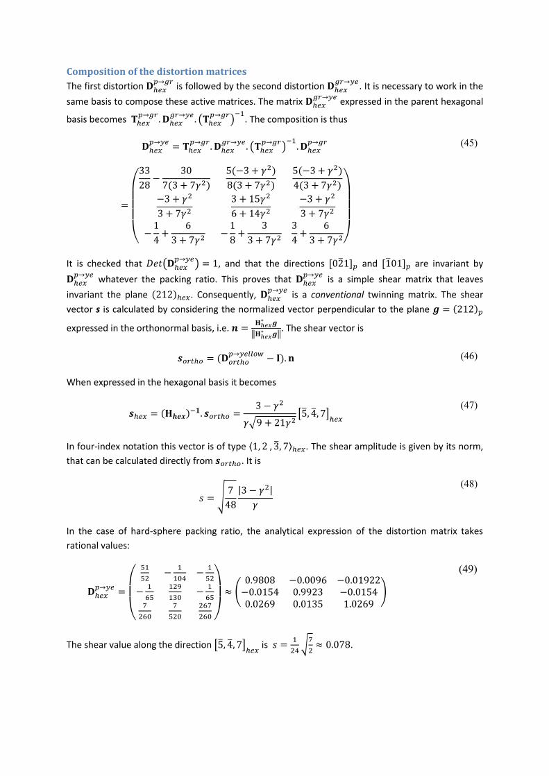
Composition of the distortion matrices
The first distortion 𝐃ℎ𝑒𝑥𝑝→𝑔𝑟
is followed by the second distortion 𝐃ℎ𝑒𝑥𝑔𝑟→𝑦𝑒
. It is necessary to work in the
same basis to compose these active matrices. The matrix 𝐃ℎ𝑒𝑥𝑔𝑟→𝑦𝑒
expressed in the parent hexagonal
basis becomes 𝐓ℎ𝑒𝑥𝑝→𝑔𝑟
. 𝐃ℎ𝑒𝑥𝑔𝑟→𝑦𝑒
. (𝐓ℎ𝑒𝑥𝑝→𝑔𝑟
)−1
. The composition is thus
𝐃ℎ𝑒𝑥𝑝→𝑦𝑒
= 𝐓ℎ𝑒𝑥𝑝→𝑔𝑟
. 𝐃ℎ𝑒𝑥𝑔𝑟→𝑦𝑒
. (𝐓ℎ𝑒𝑥𝑝→𝑔𝑟
)−1. 𝐃ℎ𝑒𝑥𝑝→𝑔𝑟
=
(
33
28−
30
7(3 + 7𝛾2)
5(−3 + 𝛾2)
8(3 + 7𝛾2)
5(−3 + 𝛾2)
4(3 + 7𝛾2)
−3 + 𝛾2
3 + 7𝛾23 + 15𝛾2
6 + 14𝛾2−3 + 𝛾2
3 + 7𝛾2
−1
4+
6
3 + 7𝛾2−1
8+
3
3 + 7𝛾23
4+
6
3 + 7𝛾2)
(45)
It is checked that 𝐷𝑒𝑡(𝐃ℎ𝑒𝑥𝑝→𝑦𝑒
) = 1, and that the directions [021]𝑝 and [101]𝑝 are invariant by
𝐃ℎ𝑒𝑥𝑝→𝑦𝑒
whatever the packing ratio. This proves that 𝐃ℎ𝑒𝑥𝑝→𝑦𝑒
is a simple shear matrix that leaves
invariant the plane (212)ℎ𝑒𝑥. Consequently, 𝐃ℎ𝑒𝑥𝑝→𝑦𝑒
is a conventional twinning matrix. The shear
vector s is calculated by considering the normalized vector perpendicular to the plane 𝒈 = (212)𝑝
expressed in the orthonormal basis, i.e. 𝒏 =𝐇ℎ𝑒𝑥∗ 𝒈
‖𝐇ℎ𝑒𝑥∗ 𝒈‖
. The shear vector is
𝒔𝑜𝑟𝑡ℎ𝑜 = (𝐃𝑜𝑟𝑡ℎ𝑜𝑝→𝑦𝑒𝑙𝑙𝑜𝑤
− 𝐈). 𝐧 (46)
When expressed in the hexagonal basis it becomes
𝒔ℎ𝑒𝑥 = (𝐇𝒉𝒆𝒙)−𝟏. 𝒔𝑜𝑟𝑡ℎ𝑜 =
3 − 𝛾2
𝛾√9 + 21𝛾2[5, 4, 7]
ℎ𝑒𝑥
(47)
In four-index notation this vector is of type ⟨1, 2 , 3, 7⟩ℎ𝑒𝑥. The shear amplitude is given by its norm,
that can be calculated directly from 𝒔𝑜𝑟𝑡ℎ𝑜. It is
𝑠 = √7
48
|3 − 𝛾2|
𝛾
(48)
In the case of hard-sphere packing ratio, the analytical expression of the distortion matrix takes
rational values:
𝐃ℎ𝑒𝑥𝑝→𝑦𝑒
=
(
51
52−
1
104−
1
52
−1
65
129
130−
1
657
260
7
520
267
260 )
≈ (
0.9808 −0.0096 −0.01922−0.0154 0.9923 −0.01540.0269 0.0135 1.0269
)
(49)
The shear value along the direction [5, 4, 7]ℎ𝑒𝑥
is 𝑠 =1
24√7
2≈ 0.078.

Composition of the coordinate transformation matrices
The first coordinate transformation 𝐓ℎ𝑒𝑥𝑝→𝑔𝑟
is followed by the second coordinate transformation
𝐓ℎ𝑒𝑥𝑔𝑟→𝑦𝑒
. The composition of these passive matrices is simply
𝐓ℎ𝑒𝑥𝑝→𝑦𝑒
= 𝐓ℎ𝑒𝑥𝑝→𝑔𝑟
. 𝐓ℎ𝑒𝑥𝑔𝑟→𝑦𝑒
=
(
−3 + 3𝛾2
3 + 7𝛾25𝛾2
3 + 7𝛾210𝛾2
3 + 7𝛾2
8𝛾2
3 + 7𝛾2−3(1 + 𝛾2)
3 + 7𝛾28𝛾2
3 + 7𝛾2
6
3 + 7𝛾23
3 + 7𝛾23 − 7𝛾2
3 + 7𝛾2)
(50)
An equivalent orientation matrix is obtained by using the internal symmetry 𝟐210 ; it is a rotation
around the 𝒖0 = [021]𝑝 axis and of angle
𝐷 = 𝐴𝑟𝑐𝐶𝑜𝑠 (−6 + 11𝛾2
6 + 14𝛾2)
(51)
With the ideal hard sphere packing ratio, the disorientation matrix is rational
𝐓ℎ𝑒𝑥𝑝→𝑦𝑒
𝟐210 =
(
11
13−8
13−16
1331
65
33
65−64
6527
65−9
65
47
65 )
(52)
And the rotation angle is 𝐷 = 𝐴𝑟𝑐𝐶𝑜𝑠 (7
13) = 57.42°
As the rotation between the parent and yellow twins (𝑝 → 𝑦𝑒) is around the axis 𝒖0 = [021]𝑝 and
as this direction is also left invariant by the rotation associated with the (𝑝 → 𝑔𝑟) twin and by the
rotation associated with the (𝑔𝑟 → 𝑦𝑒) twin, it implies that the rotation angles should be linked by
an addition. The rotation angles around the 𝒖0 axis are given in equations (28), (43) and (51), for the
(𝑝 → 𝑔𝑟), (𝑔𝑟 → 𝑦𝑒) and (𝑦𝑒 → 𝑝) twins. Even if not obvious, it is indeed checked that
−ArcCos (6 − 𝛾2
2√(3 + 𝛾2)(3 + 7𝛾2)) + ArcCos (
−3 − 2𝛾2
√(3 + 𝛾2)(3 + 7𝛾2)) = ArcCos(
−6 + 11𝛾2
6 + 14𝛾2)
(53)
and thus also in the particular case of hard-sphere packing:
−ArcCos (√5
221) + ArcCos(−5√
5
221) = ArcCos (
7
13)
(54)
The disorientation, i.e. the equivalent rotation with the minimum rotation angle in absolute value, is
obtained with the internal symmetry 𝟐110 . The disorientation 𝐓ℎ𝑒𝑥𝑝→𝑦𝑒
𝟐110 is a rotation around the
axis [221]𝑝 and of angle
𝐷 = 𝐴𝑟𝑐𝐶𝑜𝑠 (−6 + 13𝛾2
6 + 14𝛾2)
(55)

With the ideal hard sphere packing ratio, the disorientation matrix is rational
𝐓ℎ𝑒𝑥𝑝→𝑦𝑒
𝟐110 =
(
8
13
3
13−16
13
−33
65
64
65−64
659
65
18
65
47
65 )
(56)
and the rotation angle is 𝐷 = 𝐴𝑟𝑐𝐶𝑜𝑠 (43
65) = 48.58°.
As the direction [221]𝑝 ≡ [241]𝑝 by internal symmetry, the calculated disorientation (48.5°, [221]𝑝)
between the parent crystal and the yellow twin fits exactly that obtained in the EBSD map (Fig.1c).
5. Summary of the calculations
In order to get a better overview of the results, a table summarizing the main crystallographic
characteristics theoretically calculated is given below:
Twin mode Correspondence matrix
Distortion matrix Misorientation matrix
Angle of rotation around the axis u0
(𝑝 → 𝑔𝑟) (17) (23) (25) (28)
(𝑔𝑟 → 𝑦𝑒) (35) (40) (42) (43)
(𝑝 → 𝑦𝑒) (44) (45) (50) (51)
Supplementary Table 2: Summary of the main crystallographic equations related to the three twin
modes. The last column gives the rotation angle associated with the misorientation matrix chosen
among the equivalent ones such that the rotation axis is u0.
Recommended