AD-A253 166RL-TR-92-183 II~i!1 Ii11Final Technical ReportJune 1992
EXTENDED-INTERACTION KLYSTRON FORTHE AN/TPS-43-E RADAR SYSTEM
Vaan Associates Inc. DTIcL.ECTE
JUL3 1199D
Rome LaboratoryAir Force Systems Command
Griffiss Air Force Base, NY 13441-5700
9 7 21 164 92-202481111111III/1)1111111 11111i1111111111111111lil
Although this report references limited documents listed below, nolimited information has been extracted:
RADC-TR-87-266 dated December 1987, DISTRIBUTION STATEMENT - DOD &
DOD contractors only
RADC-TR-79-139 dated June 1979, DISTRIBUTION STATEMENT , USGO agencies
This report has been reviewed by the Rome Laboratory Public AffairsOffice (PA) and is releasable to the National Technical Information Service(NTIS). At NTIS it will be releasable to the general public, includingforeign nations.
RL-TR-92-183 has been reviewed and is approved for publication.
APPROVED: $i.7U LZ
DIRK T. BUSSEYProject Engineer
FOR THE COMMANDER: ~ 4 /DONALD W. HANSON, DirectorSurveillance & Photonics Directorate
If your address has changed or if you wish to be removed from the RomeLaboratory mailing list, or if the addressee is no longer employed by yourorganization, please notify RL (OCTP) Griffiss AFB NY 13441-5700. Thiswill assist us in maintaining a current mailing list.
Do not return copies of this report unless contractual obligations ornotices on a specific document require that it be returned.
REPORT DOCUMENTATION PAGE FOMBnov 070R01
W MBNo 074028
godraer "e n =the daa naa m i cwmparg¢ and twvV the zcain d houti Sw awnei "~m, b ido wV c espe d ta
1. AGENCY USE ONLY (Leave Blank) 2. REPORT DATE a REPORT TYPE AND DATES COVERD
June 1992 Final Sep 83 - Aug 91
EXTENDED-INTERACTION KLYSTRON FOR THE AN/TPS-43-E RADAR PE-706SYSTEM PR - PRAT
6.AUTHOR($) TA - 00WU- 02
7. PERFORMING ORGANGZA GEON NAME(S) AND ADDR ESS(ES) 1 PERFORMING ORGANIZATIONVarian Associates Inc. REPORT NUMBER
Microwave Power Tuba Products F1776811 Hansen WayPalo Alto CA 94304-1031
9. SPONSORING/MONITORING AGENCY NAME($) AND ADDRESIES) 10Q SPON SORING/MON[TORING
Rome Laboratory (OCTP) AGENCY REPORT NUMBER
Griffiss AFB NY 13441-5700RL-TR-92- 183
1 1. SUPPLEMENTARY NOTES
Rome Laboratory Project Engineer: Dirk T. Bussey/OCTP/(315) 330-4381
12a. DISTRIBUTIONIAVAILA81UTY S TATEMENT 12b. DISTRIBUTION CODE
Approved for public release; distribution unlimited.
I q,_,gQSTRA.C.T (Mm-,J- 200 woos)
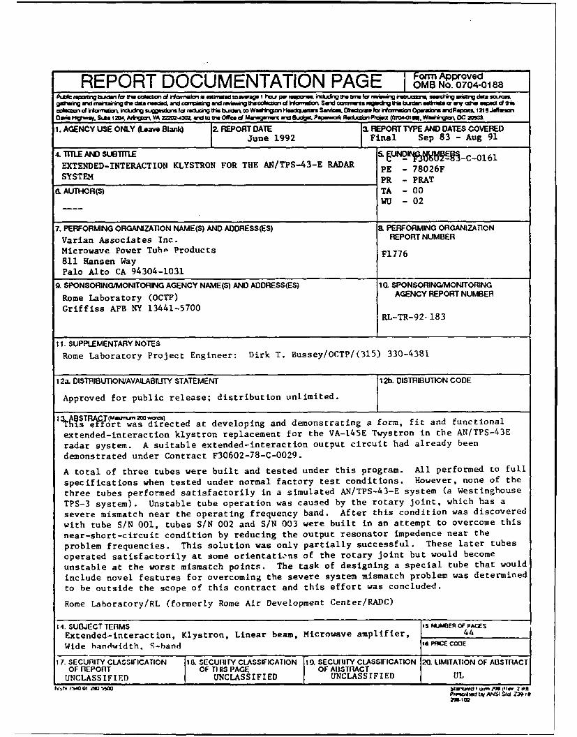
is effort was directed at developing and demonstrating a form, fit and functional
extended-interaction klystron replacement for the VA-145E Twystron in the AN/TPS-43E
radar system. A suitable extended-interaction output circuit had already been
demonstrated under Contract F30602-78-C-0029.
A total of three tubes were built and tested under this program. All performed to full
specifications when tested under normal factory test conditions. However, none of the
three tubes performed satisfactorily in a simulated AN/TPS-43-E system (a Westinghouse
TPS-3 system). Unstable tube operation was caused by the rotary joint, which has a
severe mismatch near the operating frequency band. After this condition was discovered
with tube S/N 001, tubes S/N 002 and S/N 003 were built in an attempt to overcome this
near-short-circuit condition by reducing the output resonator impedence near the
problem frequencies. This solution was only partially successful. These later tubes
operated satisfactorily at some orientations of the rotary joint but would become
unstable at the worst mismatch points. The task of designing a special tube that would
include novel features for overcoming the severe system mismatch problem was determined
to be outside the scope of this contract and this effort was concluded.
Rome Laboratory/RL (formerly Rome Air Development Center/RADC)
14. SUBJECT TERMS IS NUMBER OF PAGESExtended-interaction, Klystron, Linear beam, Microwave amplifier, 44
Wide handwidth. S-hand , PNOCE COoE
17. SECURITY CLASSIFICATION ia SECUIIY CLASSIFICATION 10. SECUIUTY CLASSIFICATION 20. LIMITATION OF ABSTRACTOFRE PORT OF Till$S PAGE OF ABlSTRACTUNCLASSIFIED UNCLASSIFIED UNCLASSIFIED UL
Pf14 I J4m0 2J 0 V iJIPruw~~imib e A 2~ f#'2-E
TABLE OF CONTENTS
Section Page No.
1.0 INTRODUCTION ........................................................................... 1
1.1 SCOPE .................................................................................. 11.2 BACKGROUND ................................................................... 1
2.0 EXTENDED-INTERACTION OUTPUT CIRCUIT KLYSTRONTECHNICAL APPROACH ......................................................... 5
2.1 EXTENDED-INTERACTION OUTPUT CIRCUIT FOR THEVKS-8345 .............................................................................. 7
2.2 OVERALL DESIGN OF THE VKS-8345 ......................... 72.2.1 Gain-Bandwidth Considerations ............................. 72.2.2 Electron Gun ........................................................... 92.2.3 VKS-8345 Buncher Section Design .......................... 92.2.4 Other Features of the VKS-8345 ............................... 10
3.0 VKS-8345 TEST PERFORMANCE DATA ................................. 12
3.1 TEST RESULTS-VKS-8345, S/N 001 .............................. 123.2 TEST RESULTS-VKS-8345, S/N 001R1 ......................... 163.3 TEST RESULTS-VKS.8345, S/N 001R2 .......................... 16
3.3.1 Initial VKS-8345, S/N 001R2 Site Tests ................. 203.3.2 VKS-8345, S/N 001R2 Testing at Westinghouse ..... 20
3.4 VKS-8345, SIN 002 ............................................................. 213.4.1 VKS-8345, S/N 002 Testing at Westinghouse .......... 24
3.5 DESIGN AND TEST OF VKS-8345, S/N 003 ................... 24
4.0 CONCLUSIONS AND RECOMMENDATIONS ....................... 29
5.0 REFERENCES ............................................................................... 30
APPENDIX A
Test Performance Sheets; VKS-8345, S/N 001Test Performance Sheets, VKS-8345, S/N 001RI
rocession For
NTIS ORA&I
DTC TAB E
Un.r~on c 3-
Du~lp ,t "UDTIC QT3JT &P e~ B
4-r1 n/or
Dist
F 1776
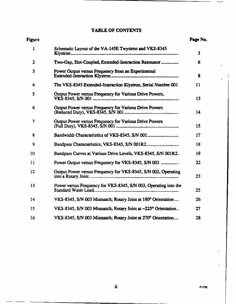
TABLE OF CONTENTS
Figure Page No.
I Schematic Layout of the VA-145E Twystron and VKS-8345Klystron .................................... 3
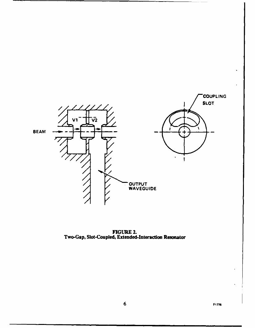
2 Two-Gap, Slot-Coupled, Extended-Interaction Resonator ............... 6
3 Power Output versus Frequency from an ExperimentalExtended-Interaction Klystron .......................................................... 8
4 The VKS-8345 Extended-Interaction Klystron, Serial Number 001 11
5 Output Power versus Frequency for Various Drive Powers,VKS-8345, S/N 001 .......................................................................... 13
6 Output Power versus Frequency for Various Drive Powers(Reduced Duty), VKS-8345, S/N 001 .............................................. 14
7 Output Power versus Frequency for Various Drive Powers(Full Duty), VKS-8345, S/N 001 ..................................................... 15
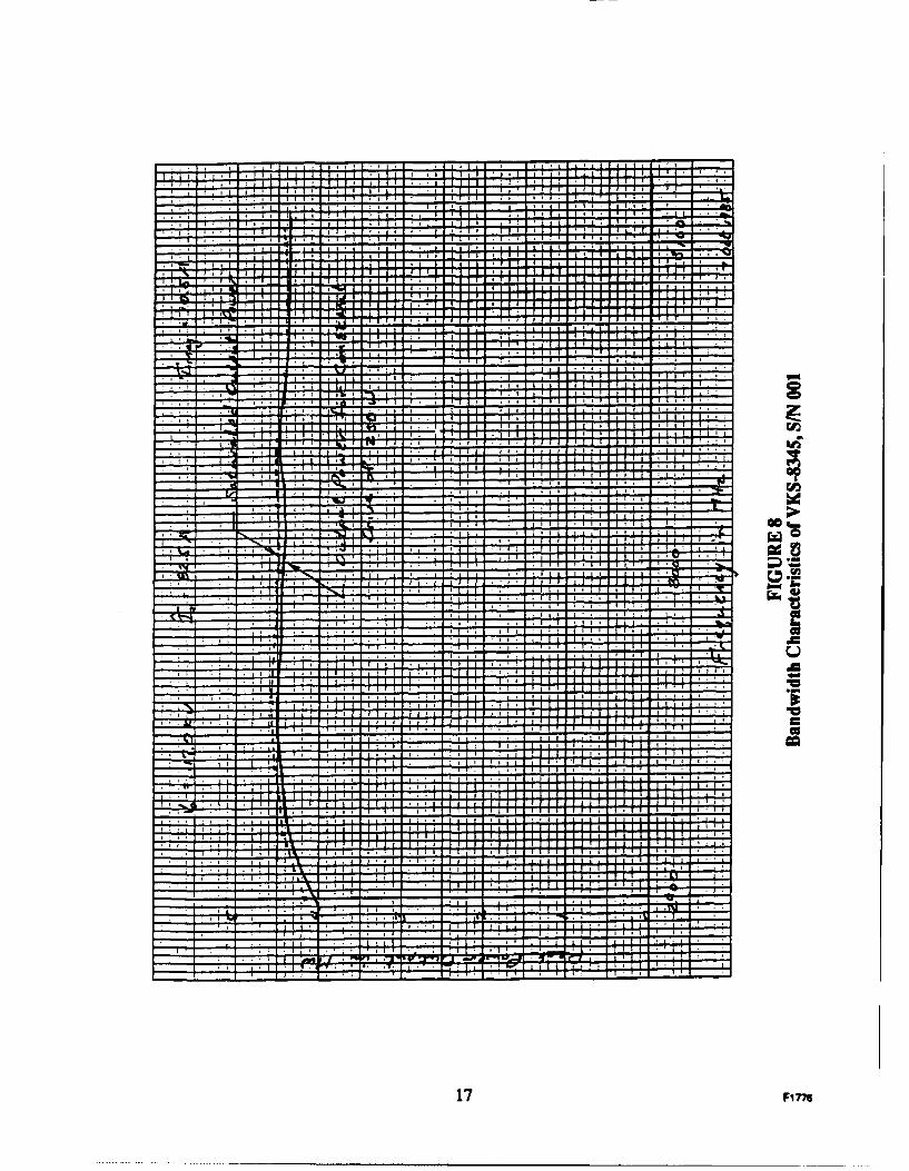
8 Bandwidth Characteristics of VKS-8345, S/N 001 .......................... 17
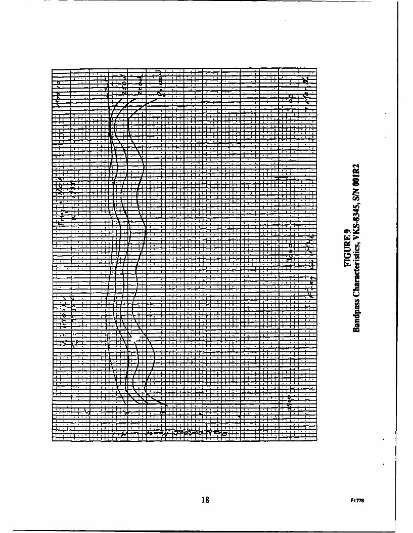
9 Bandpass Characteristics, VKS-8345, S/N 001R2 ............................ 18
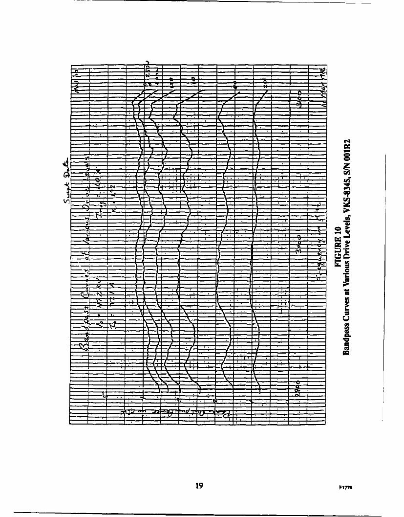
10 Bandpass Curves at Various Drive Levels, VKS-8345, S/N 001R2. 19
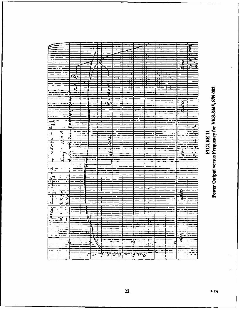
11 Power Output versus Frequency for VKS-8345, S/N 002 ............... 22
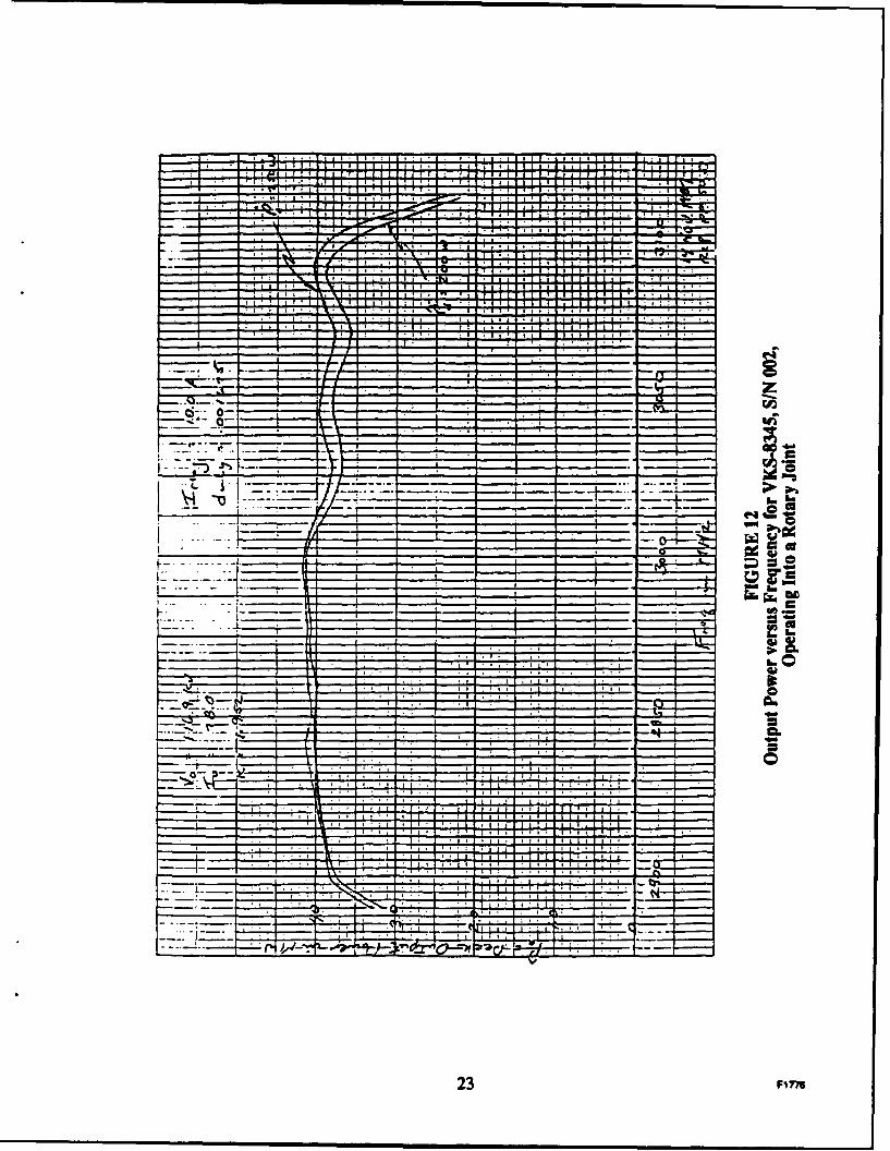
12 Output Power versus Frequency for VKS-8345, S/N 002, Operatinginto a Rotary Joint ............................................................................ 23
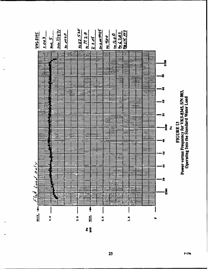
13 Power versus Frequency for VKS-8345, S/N 003, Operating into theStandard Water Load ......................................................................... 25
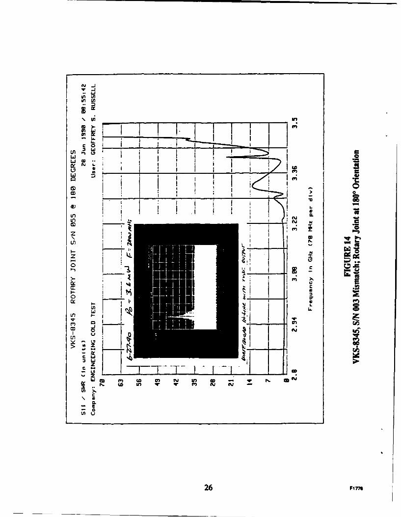
14 VKS-8345, S/N 003 Mismatch; Rotary Joint at 180 Orientation .... 26
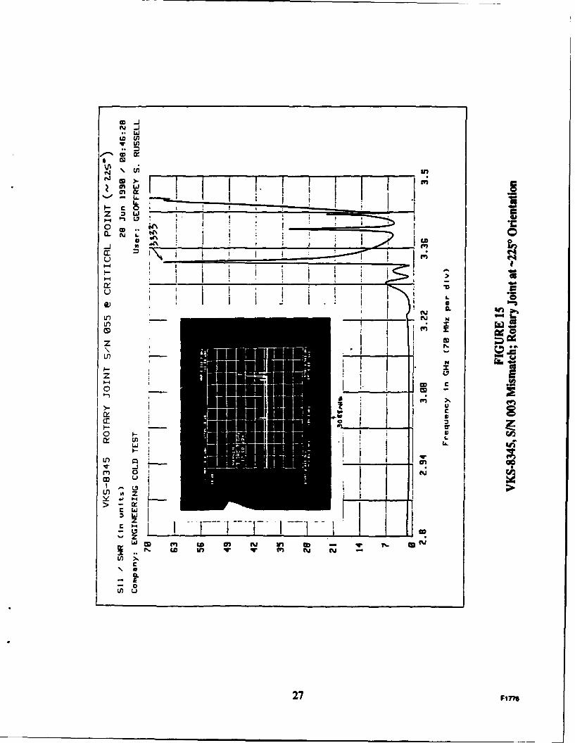
15 VKS-8345, S/N 003 Mismatch; Rotary Joint at -2250 Orientation.. 27
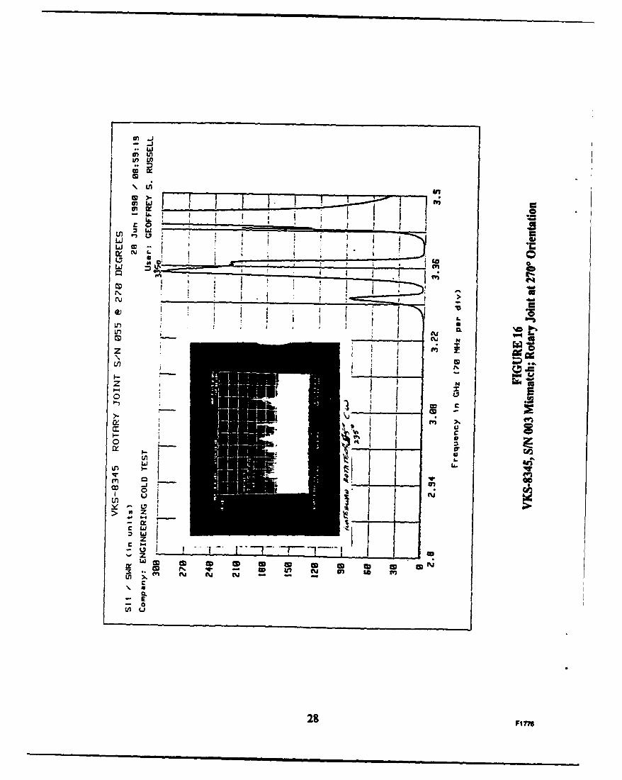
16 VKS-8345, S/N 003 Mismatch; Rotary Joint at 2700 Orientation.... 28
i gFi776
1.0 INTRODUCTION
1.1 SCOPE
This is the final technical report for Rome Air Development Center (RADC) Contract
Number F30602-83-0161. The objective of this program was to develop a cost-effective
replacement for the VA-145E Twystron ®, which is the microwave tube final amplifier in the
AN/TPS-43-E tactical radar. This work was proposed as a result of earlier development
programs on extended-interaction klystron (ElK) technology sponsored by Rome Air
Development Center under Contracts F30602-78-C-0029 and F30602-80-C-0089.
The extended-interaction klystron replacement for the VA-145E Twystron was assigned
the tube-type number VKS-8345 and is so referenced in this report.
1.2 BACKGROUND
The microwave final amplifier in the AN/TPS-43-E radar transmitter, the VA-145E
Twystron, adequately meets the system requirements for high peak power and wide
instantaneous bandwidth. Although a proven and dependable tube, the VA-145E has always
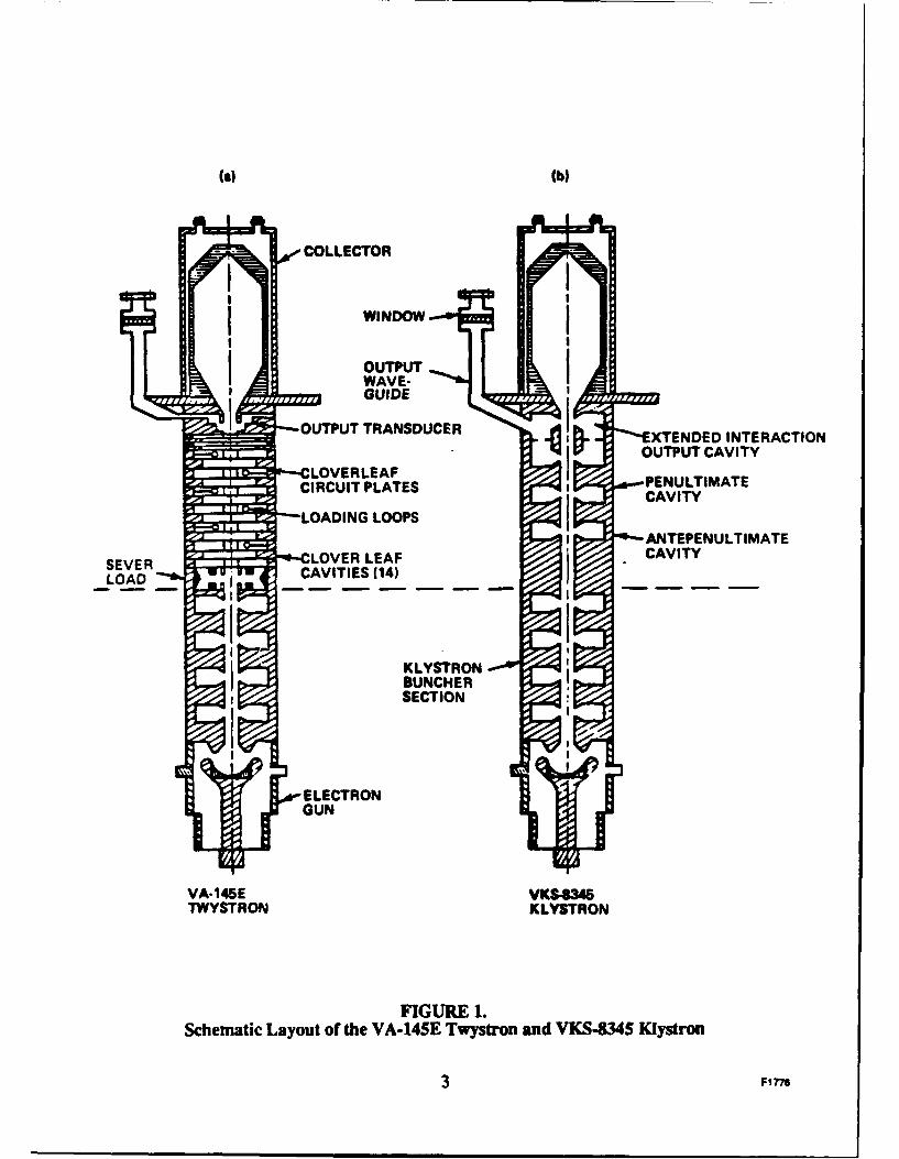
been a challenge to manufacture and repair because of its complexity. The VA-145E is a hybrid
klystron/traveling-wave tube, with four conventional klystron buncher cavities followed by a
traveling-wave output circuit (see Figure Ia). The traveling-wave output circuit contains 14 slot-
coupled cloverleaf cavities and an output coupler. As is true for all traveling-wave tube circuits,
the periodic cloverleaf cavity slow-wave structure can propagate more than one rf mode. To
maintain operation in the proper mode and avoid interference from unwanted modes, the circuit
must be carefully loaded with rf-lossy material. The input stage of the traveling-wave structure
is terminated with a delicate sever load to absorb unwanted backward waves. Each cloverleaf
cavity is loaded with rf-lossy material (Kanthal) to limit the gain and prevent unstable behavior.
Also, each cloverleaf cavity contains several loading loops coated with Kanthal to suppress the"rabbit ears" instability that occurs at the ir-point of the fundamental mode during the rise and
fall time of the beam voltage pulse.
When the Kanthal is applied correctly and each cloverleaf cavity and loading loop is
properly tuned, the VA-145E Twystron performs well. However, controlling these critical
processes during the manufacturing and repair cycles is, at best, complicated. If too little loss is
applied to the circuit, the tube will demonstrate high gain and instability; too much loss will
I F1776
result in low gain and low rf power output. In either case, the tube must be reworked and the
entire output section replaced. The manufacturing yield for this tube has traditionally been less
than is acceptable under present-day standards.
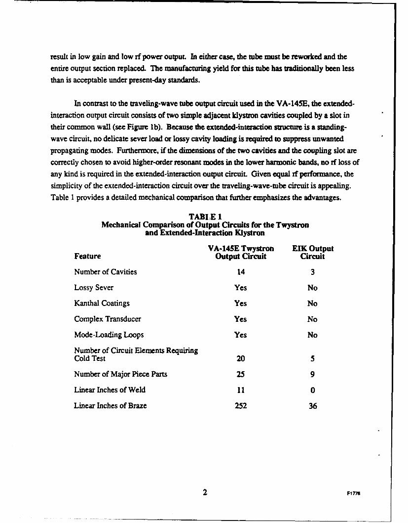
In contrast to the traveling-wave tube output circuit used in the VA-145E, the extended-
interaction output circuit consists of two simple adjacent klystron cavities coupled by a slot in
their common wall (see Figure Ib). Because the extended-interaction structure is a standing-wave circuit, no delicate sever load or lossy cavity loading is required to suppress unwanted
propagating modes. Furthermore, if the dimensions of the two cavities and the coupling slot arecorrectly chosen to avoid higher-order resonant modes in the lower harmonic bands, no rf loss ofany kind is required in the extended-interaction output circuit. Given equal rf performance, thesimplicity of the extended-interaction circuit over the traveling-wave-tube circuit is appealing.Table 1 provides a detailed mechanical comparison that further emphasizes the advantages.
TABLE IMechanical Comparison of Output Circuits for the Twystron
and Extended-Interaction Klystron
VA-14SE Twystron ElK OutputFeature Output Circuit Circuit
Number of Cavities 14 3
Lossy Sever Yes No
Kanthal Coatings Yes No
Complex Transducer Yes No
Mode-Loading Loops Yes No
Number of Circuit Elements RequiringCold Test 20 5
Number of Major Piece Parts 25 9
Linear Inches of Weld 11 0
Linear Inches of Braze 252 36
2 F1776
(a) (b)
COLLECTOR
WINDOW
OUTPUTIWAVE-GUIDE
OUTPUT TRANSDUCER i'XTENDED INTERACTIONq OUTPUT CAVITY
LOVERLEAF PENULTIMATECIRCUIT PLATES CVT
LOADING LOOPSANTEPENULTIMATE
SVRLOVER LEAF CAVITY
KLYSTRONBUNCHERSECTION
VA-145E VKS.64TWYSTRON KLYSTRON
FIGURE 1.Schematic Layout of the VA-14SE Twystron and VKS434S Klystron
3 Fl 776
The extended-interaction klystron also had the potential to significantly improvereliability in field operation. Failed VA-145E's returned frtm the field exhibit a high incidenceof electron-beam damage on the relatively delicate cloverleaf cavity plates. The cause of thisdamage is either magnetic focusing anomalies or unprotected waveguide arcing. Either of theseconditions can cause the electron beam to diverge and strike the cloverleaf cavity plates. In the
extended-interaction output circuit as shown in Figure lb, the drift tube and cavity sections areinherently more rugged and hence more tolerant of any adverse operating condition encounteredin the field. The advantages of the extended-interaction klystron over the VA-145E Twystronwere quantified in a life-cycle cost comparison analysis.I Included in this study were themanufacturing costs, repair costs, and expected improvements in tube life. The results of this
study clearly favor the extended-interaction klystron. With this background information,development of the VKS-8345 extended-interaction klystron began.
4 F1ne
2.0 EXTENDED-INTERACTION OUTPUT CIRCUIT KLYSTRONTECHNICAL APPROACH
The simplest form of an extended-interaction output circuit is two adjacent klystroncavities coupled by a slot in their common wall. When used as an output circuit, only one of thecavities (usually the second) is directly coupled to the external load. This type of circuit (shownin Figure 2) has three fundamental natural resonant modes: the x mode, the 2n mode, and theslot mode. In the x mode, the gap rf voltages are approximately 180 degrees out of phase; in the27 mode, the gap rf voltages are in phase. The slot mode occurs at a frequency generallydetermined by the dimension of the coupling slot between the cavities.
The extended-interaction output circuit can be designed to operate in either the 71 mode orthe 2n mode. Each of these modes, when well separated in frequency, acts as a single-tunedresonator. However, because of the higher intrinsic impedance of the two-cavity resonator,either mode will have nearly twice the bandwidth potential of a single cavity. The bandwidthcan be further improved for either mode by the addition of a filter cavity in the output coupler toform a filter-loaded resonator. In this approach, the 7t mode and 271 mode remain well separatedin frequency, and the circuit is operated only near the frequency of the chosen mode.
Although the two-cavity, single-mode approach described in the proceeding paragraphoffers significant bandwidth improvement over a single-cavity output system, a differentapproach can provide even more bandwidth. Instead of choosing to operate in one or the other ofthe two fundamental modes, it is possible to dimension the coupling slot between cavities so boththe 2-mode and the 2n-mode frequencies are closely spaced and lie near or within the desiredoperating band. In this case, both modes contribute to the interaction impedance, yielding adouble-peaked impedance response. An extended-interaction output circuit designed in thismanner is called an .verlapping-mode circuit. This approach, which has even more bandwidththan the filter-cavity loaded-n-mode or 22-mode circuits, was the configuration chosen for theVKS-8345 extended-interaction klystron.
Unlike a traveling-wave output circuit, the stability of the three fundamental modes (itmode, 22 mode, and the slot mode) is analytically predictable. When the cavity and slotdimensions are properly chosen, the three modes will be stable at all beam voltages and currentsto well above the operating levels. This fact was amply demonstrated on earlier extended-interaction klystron programs. 2
5 FIi 7
COUPLING
SLOT
FIGURE 2.Two-Gap, Slot-Coupled, Extended-Interaction Resonator
6 Fire
Stable operation of the fundamental modes is a straightforward achievement. However,
complete stability requires the circuit to be free of higher-order modes in all the lower harmonic
bands of the fundamental operating range. This condition is not always easily achieved. Cavityand slot dimensions optimized for the fundamental frequency range may produce in-bandharmonic resonances. Thus, the design of the output circuit becomes an iterative processwherein the optimum circuit dimensions for fundamental operation may have to be compromised
to achieve mode-free harmonic bands. As we will discuss later, such was the case in this
program.
2.1 EXTENDED-INTERACTION OUTPUT CIRCUIT FOR THE VKS-8345
Because of the previous work on extended-interaction circuits under Rome Air
Development Center Contract Number F30602-78-C-0029, the development of a new output
circuit for the VA-145E with ample impedance-bandwidth product was a low-risk effort. Under
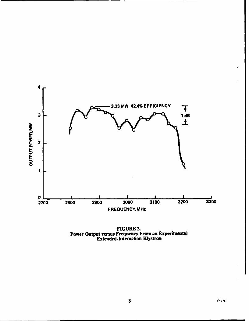
the earlier contract, a two-cavity extended-interaction output circuit was developed and installedon a standard VA-145E in place of the traveling-wave-tube output circuit. Two additional fixed-
tuned buncher cavities were also installed as shown in Figure 1. The full bandwidth of theoutput circuit was evaluated by tuning the buncher cavities to achieve saturated gain at eachfrequency. At a beam voltage of 110 kV, a 1-dB bandwidth of 12% was achieved with a
minimum power output of 2.5 megawatts (see Figure 3). These results demonstrated that a two-
cavity extended-interaction output circuit could easily provide the bandwidth, power output, and
efficiency required by the AN/TPS-43-E radar system.
The actual design of the extended-interaction output circuit for the VKS-8345, Serial
Number 001, was produced following the procedures documented in the earlier programs.2 ,3
Because the extended-interaction output circuit has more than enough bandwidth for this
application, the major task of this program was to achieve sufficient gain-bandwidth performance
from the input buncher section.
2.2 OVERALL DESIGN OF THE VKS-8345
2.2.1 Gain-Bandwidth Considerations
To be a form, fit, and functional replacement for the VA- 145E, the VKS-8345
must operate in the existing VA-145E focusing solenoid. This means the tube's input-to-output
7 Fi776
4
- 3.33 MW 42.4% EFFICIENCY T3 1 dB
3_22
I.-
01
0 I I I
2700 2800 2900 3000 3100 3200 3300
FREQUENCY, MHz
FIGURE 3.Power Output versus Frequency From an Experimental
Extended-Interaction KIystron
8 F7e
pole-piece dimension is fixed. Within this length the VA-145E provides ample gain because the
traveling-wave-tube circuit, in addition to coupling power off the beam, provides useful gain.
Such is not the case in the extended-interaction output circuit. All of the gain
must be provided by the input buncher section. The two additional buncher cavities just prior to
the output circuit are both tuned relatively high in frequency (out of band) to enhance efficiency;hence, they add little gain. Stated another way, a Twystron has greater gain per unit length than
does a klystron, all other things being equal.
Several options were available to produce adequate gain-bandwidth in the buncher
section of the VKS-8345. Our choice was to reduce the drift-tunnel and beam diameters slightly.
These changes increase the beam-to-cavity coupling and add electrical length to the tube.
Increasing the beam-to-cavity coupling also contributes to improved efficiency.
2.2.2 Electron Gun
The standard VA-145E electron gun was modified to produce a smaller beam that
would be compatible with the reduction in drift-tunnel diameter from 0.75. inches to 0.70 inches.
The change to the gun included reducing the cathode button's radius of curvature, modifying theanode shape, and reshaping the iron input pole piece. A model of the modified electron gun wasbuilt and tested in our beam analyzer. The new beam has a diameter of 0.50 inches and only 7%scalloping under normal focusing conditions. Stable beam operation was achieved over a 20%variation in magnetic focusing field. These results are an improvement over the standard
VA- 145E gun.
2.2.3 VKS-8345 Buncher Section Design
If the tube is to meet the required bandwidth and power-output performance, the rfbuncher section must present a properly bunched beam to the extended-interaction output circuitat each frequency within the operating band. The critical variables are the frequencies andloaded Q's of the cavities and the electrical distances between them. Optimizing theseparameters is greatly simplified by utilizing several computer codes that simulate klystronbehavior under both small-signal and large-signal saturated conditions. After a number ofiterations, a combination of cavity parameters was found that provided a satisfactory gain-bandwidth product within the VA-145E pole-piece-to-pole-piece length. In the final buncher
section design, the input cavity is heavily loaded by the input loop. The second cavity is loaded
9 Fine
with a coupling loop connected to an external load. Cavities three and four have no coupling
loops; neither do the two penultimate cavities. The first four cavities have two inductive
diaphragm tuners that provide a tuning range of approximately 40 MHz. These trim tuners are
used to compensate for imperfect data in the computer model and variations in the manufacturing
process.
2.2.4 Other Features of the VKS-345
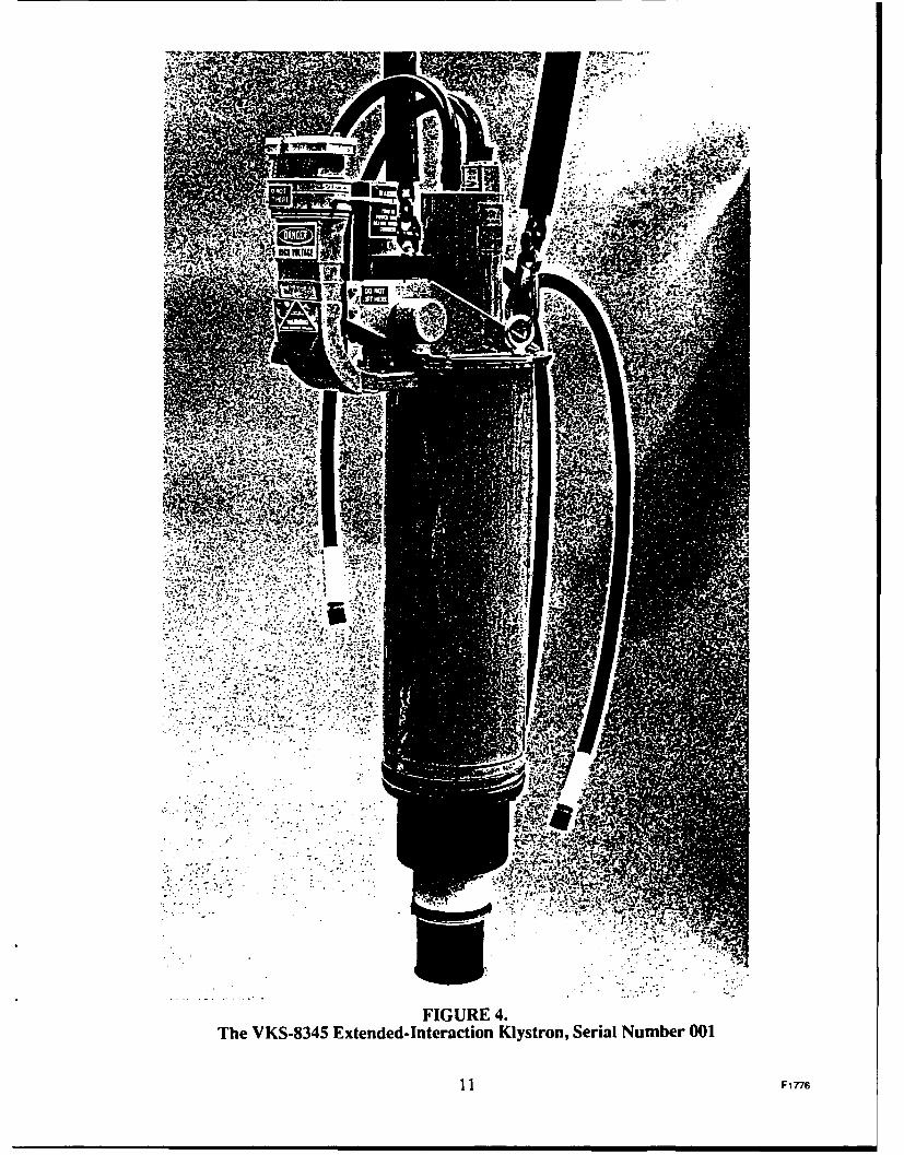
Many of the components used on the VKS-8345 were taken directly from the
VA- 145E. The ceramic high-voltage seal, collector, and output window were adapted without
change. Most of the external hardware items are identical to those used on the VA-145E. When
fully dressed, the VKS-8345 is nearly indistinguishable from the VA-145E. Figure 4 is a
photograph of the VKS-8345, Serial Number 001.
10 FIfls
.o.8 . -'
FIGURE 4.The VKS-8345 Extended-Interaction Klystron, Serial Number 001
11 Fl 6
3.0 VKS4345 TEST PERFORMANCE DATA
3.1 TEST RESULTS-VKS-8345, S/N 001
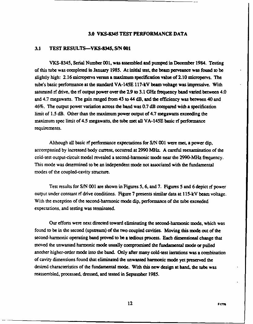
VKS-8345, Serial Number 001, was assembled and pumped in December 1984. Testingof this tube was completed in January 1985. At initial test, die beam perveance was found to beslightly high: 2.16 micropervs versus a maximum specification value of 2.10 micropervs. The
tube's basic performance at the standard VA-145E 117-kV beam voltage was impressive. Withsaturated rf drive, the rf output power over the 2.9 to 3.1 GHz frequency band varied between 4.0and 4.7 megawatts. The gain ranged from 43 to 44 dB, and the efficiency was between 40 and
46%. The output power variation across the band was 0.7 dB compared with a specificationlimit of 1.5 dB. Other than the maximum power output of 4.7 megawatts exceeding themaximum spec limit of 4.5 megawatts, the tube met all VA-145E basic rf performance
requirements.
Although all basic rf performance expectations for S/N 001 were met, a power dip,
accompanied by increased body current, occurred at 2990 MHz. A careful reexamination of thecold-test output-circuit model revealed a second-harmonic mode near the 2990-MHz frequency.This mode was determined to be an independent mode not associated with the fundamentalmodes of the coupled-cavity structure.
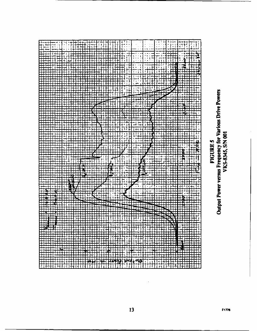
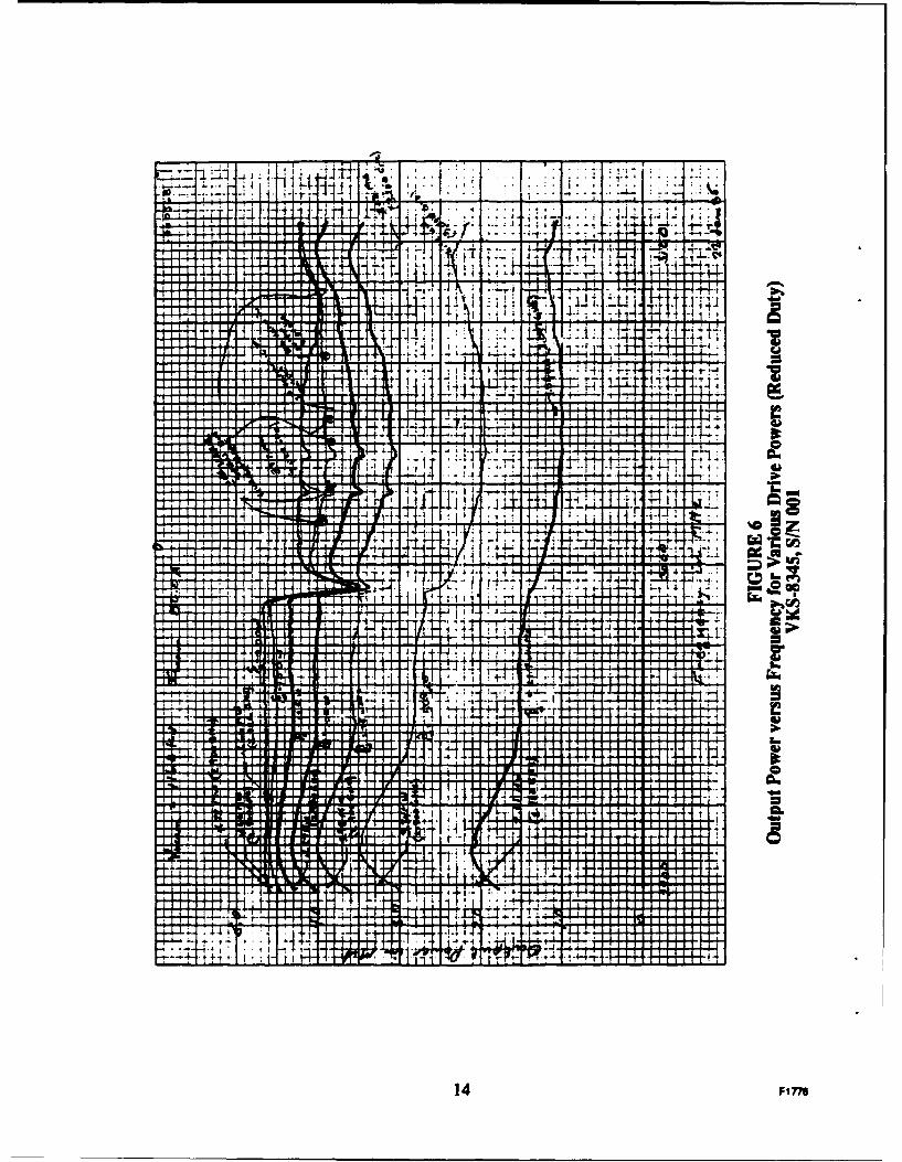
Test results for S/N 001 are shown in Figures 5, 6, and 7. Figures 5 and 6 depict rf power
output under constant rf drive conditions. Figure 7 presents similar data at 1 15-kV beam voltage.With the exception of the second-harmonic mode dip, performance of the tube exceeded
expectations, and testing was terminated.
Our efforts were next directed toward eliminating the second-harmonic mode, which was
found to be in the second (upstream) of the two coupled cavities. Moving this mode out of the
second-harmonic operating band proved to be a tedious process. Each dimensional change that
moved the unwanted harmonic mode usually compromised the fundamental mode or pulledanother higher-order mode into the band. Only after many cold-test iterations was a combinationof cavity dimensions found that eliminated the unwanted harmonic mode yet preserved the
desired characteristics of the fundamental mode. With this new design at hand, the tube wasreassembled, processed, dressed, and tested in September 1985.
12 Fi7-6
r r':.1 I
44-H. T+ i 1, -4---- -14-r-H 4 i I t 1 I LlTW
+ + 4TF..... ..... .....
-44-40
-j-L.
QI I I r I
f i l l f I t i t I I I .IU I I I ; I
-14r-4H
I I I i t rv
Irl I II.Fl I I 4w
en
ICAi t . 1 : 1 1 1 1 IT-1
I I I I I if I I
H41 - H"1 1 , I l a i
If I I II
Itliltlilt
"r-,-, 7
[ i f I I I
4-,
11414-
4
13 F1776
44
I If7tIf 4.I TltIr 44
I I Itj.j 4
f7
+ -1 +
141..... . .....
ANIUMMAI It I A.T lab
I A _L I MRa'a.14LL'IL lip
W*cwW an
4 4-14-1 0 L. in
i I aIALL 77". ' _j; I - 1 0 >
I lit-f: A;
I f I I4-4[it JIM F I it
Al 44' 1
Au. if IIILo
A
CL
L A# r
If
t if II t. Il IZ1 1 1 1 1 1 1
: t 1 1 I f I f 1 1
14 Fine
IGN
-T-T.TT ad4i -.-- 7-- =jk7
il. +++H 0.. .1 4 7i 7 T-. 4. - . -&.- t! I - I i- + -I fill. I I
t tt -1-2 114
flil p -4 1. I ON-A -1
It
hal I
M-1 I If- ...... ...... Tlk
I I II I I I I I , I - IF 1 1 1.11
ILP I I I I IMilli I I I I is I I I III
11 1 IA I IIn" 1 11IN; I I
I le i I I If I ILr-1 I I
Y-1 1V I
Ch 11 INT-T-T-T-T-1
-T-T.. ........
Cis
I 1 11 1 if
it ... .... c
If] 1-1 1 1 1 1 A 44 4. =>I i ti -1-tH 1-H t
ram
I I I ' ll , jio , I I + i I II I I i
I I f l i l lIN, 1w I I II J.11 I T I I I I if
LM I I
IL 111 06
I fT f I I f fill I I I IIs. I I I L
t L AJ IL
I L I -LuTr
TtrH T
15 Fi776

3.2 TEST RESULTS -VKS-8345, S/N OlRI
When the tube was reassembled, the electron gun cathode-anode spacing was increased
slightly to reduce the gun perveance. This adjustment was only partially successful, as the
perveance proved to be right at the maximum limit of 2.1 micropervs. Under these conditions,the maximum rf power output from the rebuilt tube still exceeded the maximum spec limits, but
the second-harmonic mode was entirely eliminated.
Because the tube exceeded the maximum power output specification but met all otherperformance specifications, we decided to reduce the electron-gun perveance by pulling the gunback from the anode with an external fixture. With the gun perveance reduced to2.05 micropervs, the tube was retested in October 1985 and met all performance specifications
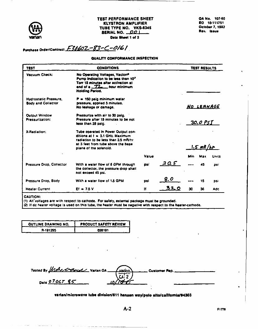
with the constant rf drive power of 250 watts. Typical test data at 117 kV are shown in Figure 8.The tube was then subjected to all VA- 145E electrical and mechanical acceptance testprocedures. The tube passed all tests; copies of the Test Performance Sheets are included in
Appendix A.
After tests on S/N 001RI were completed in Palo Alto, it was shipped to Fort Monroe,Virginia, for testing in an ANfTPS-43-E radar system. However, after installation and during
checkout in the system transmitter, the tube lost its vacuum when the ceramic insulator on theVaclong pump was accidently broken. The tube was returned to Varian for repair.
3.3 TEST RESULTS -VKS-8345, S/N 001R2
VKS-8345, Serial Number 001, was repaired, pumped, and dressed for test in February
1986. A new electron gun was used that had been modified to further reduce the gun perveance.The rebuilt tube was tested in March and again successfully met all specification requirements.
Sample test data curves are shown in Figures 9 and 10, and copies of the Test PerformanceSheets are provided in Appendix A. At the end of March 1986, the tube was shipped back to
Fort Monroe, Virginia, for field testing as Serial Number 001R2.
16 Firm
FT I i
IfU
I If -
ItU
lilt
Wil
I7 Fin
OUI PiArU
II
I S I' *
I, , T I F I I
* 9 9 * I * *-
9 9 9 9 9 * . 'I I
*f I. if C- 5'. ,
9 1 ~ 9 9 9 -- . 9 I I' 'p 11 ,k
V I I *9 .9 9 9 99 9 5 S . 15 99, 9. .9
18 F1cc
II
I'Lu
If I I
III ff I
mlU
19 P17W
3.3.1 Initial VKS4345, S/N 001R2 Site Tests
When sufficient time to test the tube could not be scheduled at Fort Monroe,
arrangements were made to install and operate the tube at Luke Air Force Base in Arizona. InJuly 1986 the first system operation was attempted. In this initial test no meaningful data were
obtained. Each time the tube was snapped on at full voltage, it arced off. Sufficient time in the
equipment was not available to investigate the problem.
When S/N 001R2 was returned to Varian and installed back in the test set, it arcedupon initial turn-on. The tube subsequently stabilized and performed normally. Further
investigations uncovered no problems; therefore, plans were made to schedule another test in an
AN/TPS-43-E system.
3.3.2 VKS-8345, S/N 001R2 Testing at Westinghouse
When a longer period of test time in an operating AN/TPS-43-E system could notbe scheduled, Westinghouse Corporation agreed to test the tube in their TPS-70 test bed. TheTPS-70 is an upgraded version of the AN/TPS-43-E radar system. After installation in theWestinghouse system, S/N 001R2 was initially operated into the dummy water load. Under
these conditions, tube performance was normal and closely matched the Varian test performance.
However, when operation was switched into the antenna system, the tube became unstable,displayed high body current, and was shut down by high reflected rf power. Stable operationwas not achieved under any of the test conditions tried. Investigations revealed the possible
cause of the problem (both in the TPS-70 and AN/ITPS-43-E systems) was a severe waveguidemismatch just outside the high end of the frequency band. To test this hypothesis, a suitablewaveguide circulator was obtained and installed in the TPS-70 waveguide system. With the
circulator in place, the tube performed very well, with test results similar to those obtained when
operating directly into the dummy water load. The source of most of the severe mismatch just
outside the upper band edge was subsequently traced to the rotary joint. This situation, togetherwith the fact that the extended-interaction output circuit on the VKS-8345 has a much wider
impedance bandwidth than required, creates the necessary conditions for inducing self-
oscillations in the extended-interaction klystron.
20 F1776
This anoysis suggested two solutions to the problem: either reduce the mismatch
of the rotary joint, or reduce the out-of-band impedance o the output circuit at the high end of
the frequency band. Since it was not feasible to modify/replace the rotary joints in all existingAN/TPS-43-E radar systems, the logical choice was to modify the impedance bandwidth
characteristic of the extended-interaction output circuit.
3.4 VKS-8345, S/N 002
Rather than rebuild S/N 001R2 again, a second tube nearly identical to S/N 001 wasassembled. In the new tube, the output circuit's bandpass characteristic was shifted lower infrequency to reduce the out-of-band impedance above the high end of the frequency band. SerialNumber 002 was completed and tested in October 1987. The tube performed very well whenoperated into a standard water load and met all specifications. Sample test data are shown inFigure 11. When a borrowed AN/TPS-43-E rotary joint was installed in the test set in a fixedorientation, the tube continued to perform well, yielding essentially the same test data as shownin Figure 12. To confirm the improved performance of S/N 002, S/N 001R2 was installed in atest set and operated into the rotary joint. Above a beam voltage of 72 kV, S/N 001R2 exhibitedoscillations at a frequency of 3340 MHz. A VSWR-versus-frequency plot for the rotary jointshowed a good in-band match, but a 12:1 mismat% was present at approximately 3340 MHz.The higher impedance level of the output circuit in S/N 001R1 was apparently sufficient to createan unstable operating condition in the face of a severe mismatch.
As a final check, S/N 002 was returned to the test socket and operated at full duty into the
rotary joint. Again the tube performed normally with no evidence of oscillations or instabilities(see Figure 12). In all of the above tests, the rotary joint was held in a fixed position.
21 F776
ILI
0
-E-
22 F1 776
I FC
0.-
as
23 F1776
3.4.1 VKS.8345, S/N 002 Testing at Westinghouse
S/N 002 was finally installed and tested in a TPS-70 transmitter at Westinghouse
in April 1988. The tube operated well in the system at certain orientations of the antenna, but at
other orientations oscillations occurred. Both self-oscillations and drive-induced oscillations
were observed, and at sufficiently high power levels the tube would trip off. At those antennaorientations producing satisfactory operation, the measured performance was comparable toVarian test data. Although VKS-8345 S/N 002 was not usable in the TPS-43/70 systems, itsperformance was an improvement over that of S/N 001R2.
3.5 DESIGN AND TEST OF VKS-8345, SIN 003
With the expectation that the design of the extended-interaction output circuit could be
modified to operate benignly in the presence of the severe mismatch near the upper band edge, athird tube was built and tested. As described earlier in Section 2.0, in an overlapping-modeextended-interaction output circuit, both the n mode and the 2n mode are located in or near thedesired bandpass of the circuit. In the original design, the 2N mode, which is the upper mode,was located at about 3227 MHz. In S/N 003, the 2n-mode point was reduced to 3168 MHz.Here again the goal was to reduce the out-of-band impedance at the troublesome 3340 MHz
frequency range.
S/N 003 was assembled and tested in June 1990. As with the previous tubes, this tubeperformed well and met all specifications when operating into the standard water load. Sampletest data are shown in Figure 13. At the completion of tests, the rotary joint was installed in thetest set, but with provisions made to allow rotation of the joint with the water load attached.Testing into this waveguide setup produced results similar to those demonstrated by S/N 002 inthe TPS-70 transmitter at Westinghouse. S/N 003 operated satisfactorily at certain rotary-joint
orientations, but exhibited oscillations at other orientations.
A careful VSWR mapping of the rotary joint at various orientations showed themismatch in the 3340 MHz region varied from a low of 12:1 to a high of 300:1 in the worst case.Figures 14, 15, and 16 provide examples of the test data. We then concluded that further
adjustments of the extended-interaction output bandpass characteristics would probably notovercome the severe mismatch problem in the rotary joint. Since other tube-related solutions to
this problem were deemed to be outside of the scope of this contract, the program was concluded.
24 FIrM
LaLA
Z44
ww All
A)
. -.- . . . . -4--.
- -~ - 4. - -4
.j 1. . .I
25 F1776
1IxI
I Ic~IJJ - r>
I I V
wn .
L&J C
N LI I Iz
LA )c.LI~ I- ~N
I17
I mI I
-7-7 -TI
0 0 I V-
26-F 77
LIn
C" I
0.- CO a. cmI
m W)
a:-I I
-__ _ _
I I I I Ln - u
In N0U,- D_
_
z
I.-
U,
mn 0 crn
(.nhi _--Y D I-
>~>
z U
w X
~0
27 Fine6
mJ
_ _ _ _ _ _ U7
I x
L~j
WU "
LOl
m zu
02
Lflv z
> t---
I
w
28F17
4.0 CONCLUSIONS AND RECOMMENDATIONS
The results from the three VKS-8345 extended-interaction klystrons built and tested
under this program demonstrated conclusively that the extended-interaction output circuit canprovide wide bandwidths with exceptional flatness and high efficiency in a high-power klystron.
However, the goal of achieving a drop-in replacement for the VA-145E in the existingAN/TPS-43-E transmitter was not achieved because of tube instabilities induced by the severe
near-band mismatch conditions existing in the rotary joint. Two attempts to overcome theproblem by modifying the extended-interaction output circuit did not yield satisfactory results.
The problem may still be overcome by clever output-circuit design, but we need to explore new
ideas.
Other tube-related solutions to this out-of-band instability problem are possible. Onesuch idea would be to incorporate waveguide filter elements in the output waveguide of the tubeto control the amplitude and phase angle of the mismatch. While such a scheme is consideredpossible, the task was outside the scope of the present program.
Finally, the wideband extended-interaction klystron design that evolved from thisprogram is certainly a superior candidate for use in radar systems that either incorporate awaveguide circulator or have a rotary joint with a better near-band VSWR response.
29 F1776
5.0 REFERENCES
1. "Proposal for a Product Improvement Program for the TPS-43 Final Amplifier Tube,"Varian Associates Technical Proposal VATP 82-60061, April 1982.
2. "Wideband Extended Interaction Klystron," Varian Final Technical Report, Contract No.F30602-80-C-0089 for Rome Air Development Center, November 1984, includingAddendum of September 1987; Section IM Paragraph D---Output Resonator.
3. "Extended-Interaction Resonator Development," Final Technical Report, ContractNo. F30602-78-C-0029.
30 F1776
APPENDIX A
Test Performance Sheets
VKS-8345, S/N 001
Test Performance Sheets
VKS-8345, S/N OO1Rl
A-i i~
TEST PERFORMANCE SHEET OA No. 107-60KLYSTRON AMPLIFIER EO 10-1117S1
TUBE TYPE NO. VKS-8345 October 7. 1982SERIAL NO. . QJ1 Rev. Issue
Varln Data Sheet I of 2
Purchase OrderlContract 2,- "" /
QUALTY CONFORMANCE INSPECTION
TEST CONDITIONS TEST RESULTS
Vacuum Check: No Operating Voltages, VaclonPump Indication to be e than 10'Toir 15 minutes after activation atend of a .27.... hour minimumHolding Period.
Hydrostatic Pressure, P - 150 psig minimum waterBody and Collector pressure, applied 5 minutes.
No leakage or damage. NO LE4IAk GE
Output Window Pressurize with air to 30 psig.Pressurization: Pressure after 15 minutes to be not
less than 28 psig. r0 , S
X-Radiation: Tube operated In Power Output con.ditions at f - 3.1 GH. Maximumradiation to be less than 2.5 mF/hrat 3 feet from tube above the baseplane of the solenoid. J, 1"'IhP
Value Min Max Units
Pressure Drop, Collector With a water flow of 6 GPM through psi 2 0. 45 psithe collector, the pressure drop shallnot exceed 45 psi.
Pressure Drop, Body With a water flow of 1.5 GPM psi 1. 0 .- 15 psi
Heater Current Ef - 7.5 V If 2-- 30 36 Adc
CAUTION:(1) All'voltages are with respect to cathode. For safety, external package must be grounded.(2) If dc heater voltage is used on this tube, the heater must be negative with respect to the heater-cathode.
F OUTLINE DRAWING NO. PRODUCT SAFETY REVIEWR.191295 026191
Tested By ,fZS , Vahlan OA Customer Rep.
Date 07ocr 4gf" ____________
varlan/microwave tube division/61 I hateran waylpalo altollcaIfomlaIO4303
A-2 F1778
TEST PERFORMANCE SHEET CA No. 10740KLYSTRON AMPLIFIER E0 10.111751
TUBE TYPE NO. VKS-345 October 7. 192SERIAL NO. 00 1 Rev. Issue
Vw Det Shoot 2 of 2
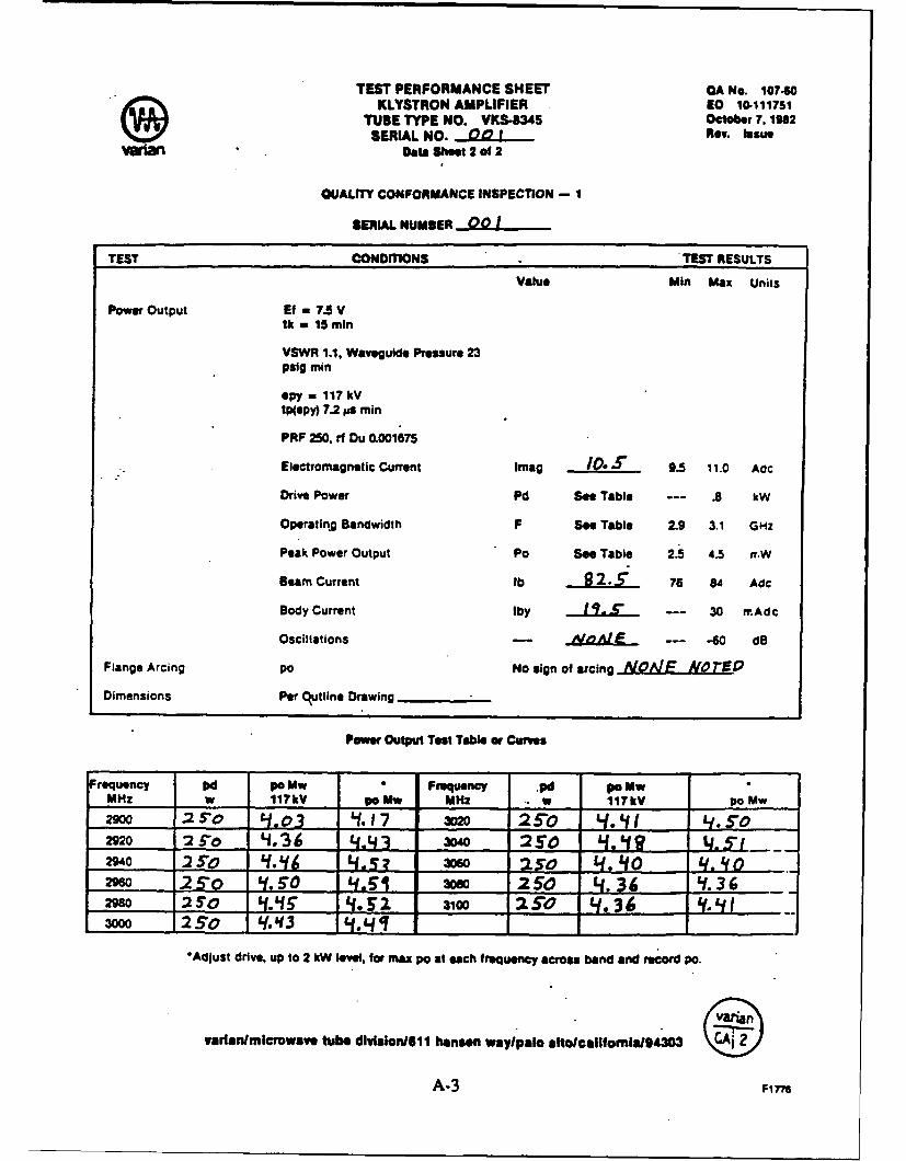
QUALITY CONFORMANCE INSPECTION - I
SERIAL NUMBER 00 1
TEST CONDITIONS TEST RESULTS
Value Min Max Units
Power Output Ef , 7.5 Vtk - 15 min
VSWR 1.1. Waveguide Pressure 23psig min
spy - 117 kV
tp(epy) 7.2 Mae min
PRF 250, rf Du 0.001675
Electromagnetic Current Imag IO. 9.5 11.0 Adc
Drive Power Pd See Table --- .8 kW
Operating Bandwidth F See Table 2.9 3.1 GHZ
Peak Power Output PO See Table 2.5 4.5 rr.W
Beam Current lb 9 2.5i 76 84 Adc
Body Current Iby I I. S_ --- 30 rr.Adc
Oscillations - ' --- -60 dB
Flange Arcing po No sign of arcing .A1FJLE. .. L '
Dimensions Per C~jtllne Drawing
Power Output Test Table or Curves
Frequency Od p0 Mw * Frequency .pd po MwMHz w 117kV po Mw MHz .. w 117kV po Mw
290 e25, 0 ' .17 3o 25o L/ 4/. 5"o2920 2£ Ard .36 443- 3W~ 2s0 4 .. Lt....2Wo :2 .o q'! 4. sosO 250 4.40 £q,.2M 25"0 f, so. 5 30 2S0 4, 36 Lt.3630 25'o .'13 _._5_ 2 _o 30 250 . 36 1
*Adjust drive, up to 2 kW level, for max po at each frequency across band and record Pa.
varlantmtcrowave tube dIvIsIon611 hansn waylpalo alto/callfomlaI/4303
A-3 F1776
TEST PERFORMANCE SHEET CA No. 10740KLYSTRON AMPLIFIER EO 10-111751
TUBE TYPE NO. VAS-8345 October 7, 1365SERIAL NO. . R I Rev. Issue
Vahi Data Shoot 1 of 2
Purchase OrderlContract PO-O )Z- ?.C O/,/
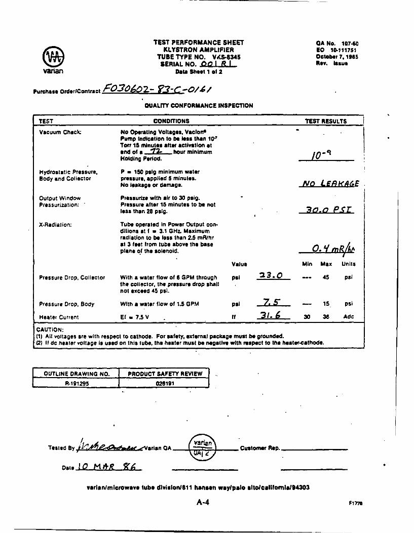
OUAuTY CONFORMANCE INSPECTION
TEST CONDITIONS TEST RESULTS
Vacuum Check: No Operating Voltages, VaclonPump indication to be less than 10-7Torr 15 minutes after activation atend of a ".12. hour minimum /0-9Holding Period.
Hydrostatic Pressure, P - 150 palg minimum waterBody and Collector pressure, applied 5 minutes.
No leakage or damage. AI LEA .&E
Output Window Pressurize with air to 30 psig.Pressurization: Pressure after 15 minutes to be not
less than 28 psig. 3,0.t Psr
X-Radiation: Tube operated in Power Output con-ditions at f a 3.1 GHL Maximumradiation to be less than 2.5 mR/hrat 3 feet from tube above the baseplane of the solenoid.
Value Min Max Units
Pressure Drop, Collector With a water flow of 6 GPM through psi 2 3. 0 -- 45 psithe collector, the pressure drop shallnot exceed 45 psi.
Pressure Drop, Body With a water flow of 1.5 GPM psi ... 5" -- 15 psi
Heater Current Ef a 7.5 V if 2.- 30 36 Adc
CAUTION:(1) All voltages are with respect to cathode. For safety, external package must be grounded.(2) If dc heater voltage is used on this tube, the heater must be negative with respect to the heater-cathode.
OUTLINE DRAWING NO. PRODUCT SAFETY REVIEWR-19"5 026191
Tested By t - - CA, Cusrtaten OA Rep.
Date 10 M *R T (
varianlmicrowave tube division/11 hanson waylpolo aIto/ealifomla/94303
A-4 Fi 77a
TEST PERFORMANCE SHEET OA No. 107.60KLYSTRON AMPLIFIER EO 10-111751
TUBE TYPE NO. VKS-8345 October 7,1982SERIAL NO. 00 1 AJI Rev. Issue
variant Data Shoot 2 of 2
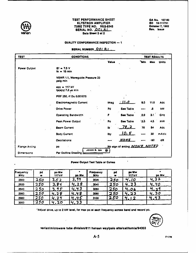
OUALITY CONFORMANCE INSPECTION - 1
SERIAL NUMBER 00 1 .I
TEST CONDITIONS TEST RESULTS
Value 'Min Max Units
Power Output Ef - 7.5 Vtk - 15 min
VSWR 1.1, Waveguide Pressure 23psig min
spy - 117 kV
tp(epy) 7.2 s min
PRF 250, rf Du 0.001675
Electromagnetic Current Imag .J. ... 9.5 11.0 Adc
Drive Power Pd See Table -- .8 kW
Operating Bandwidth F See Table .2.9 3.1 GHz
Peak Power Output Po See Table 2.5 4.5 mW
Beam Current lb . 78.2 76 84 Adc
Body Current Iby 10. 6* --- 30 mAdc
Oscillations -- NONE - -60 dB
Flange Arcing Io No sign of arcing VA k AIOTED_JOHN S. GA
Dimensions Per Outline Drawing
Power Output Test Table or Curves
Frequency pd po Mw Frequency pd po MwMHz w 117kV po Mw MHz w 117kV po Mw2900 :2 510 3.F",2 3.71/ 3020 5,0 L1Q. to 4. 322920 :25 3. ' 1. 2 3040 2.50 ', 2 3 .If02940 250 3.15 . L-. 13 3o6o 25O . .(, . 2q2960 250 il ,2 L.9 Wo :250 S1.23 4.30
"2980 L0 2At L 3100 2.L"0 1 43000 25"0 4.20 4. 33
'Adjust drive, up to 2 kW level, for max po at eact frequency across band and record pa.
varlanlmicrowave tube division/611 hansen waylpalo altoicalifomiaI94303
A-5 F177e
I
OF
ROME LABORATORY
Rome Laboratory plans and executes an interdisciplinary program in re-search, development, test, and technology transition in support of Air
Force Command, Control, Communications and Intelligence (C I) activitiesfor all Air Force platforms. It also executes selected acquisition programsin several areas of expertise. Technical and engineering support withinareas of competence is provided to ESD Program Offices (POs) and otherESD elements to perform effective acquisition of C31 systems. In addition,Rome Laboratory's technology supports other AFSC Product Divisions, theAir Force user community, and other DOD and non-DOD agencies. RomeLaboratory maintains technical competence and research programs in areasincluding, but not limited to, communications, command and control, battlemanagement, intelligence information processing, computational sciencesand software producibility, wide area surveillance/sensors, signal proces-sing, solid state sciences, photonics, electromagnetic technology, super-conductivity, and electronic reliability/maintainability and testability.
Recommended