(1/139)
External Control NEC LCD Monitor Rev.1.3 (G4)
INDEX
I. Application ............................................................................................................................................. 4 II. Preparation ........................................................................................................................................... 4 2. Connectors and wiring ......................................................................................................................... 4 2.1 RS-232C Remote control .................................................................................................................... 4 2.2 LAN control ......................................................................................................................................... 5 III. Communication specification ............................................................................................................ 6 3. Communication Parameter .................................................................................................................. 6 3.1 RS-232C Remote control .................................................................................................................... 6 3.2 LAN control ......................................................................................................................................... 6 3.3 Communication timing ....................................................................................................................... 6 4. Communication Format ........................................................................................................................ 7 4.1 Header block format (fixed length) ................................................................................................... 8 4.2 Message block format ...................................................................................................................... 10 4.3 Check code ....................................................................................................................................... 12 4.4 Delimiter ........................................................................................................................................... 13 5. Message type ...................................................................................................................................... 14 5.1 Get current Parameter from a monitor. .......................................................................................... 14 5.2 "Get parameter" reply ...................................................................................................................... 15 5.3 Set parameter ................................................................................................................................... 17 5.4 "Set parameter" reply ...................................................................................................................... 18 5.5 Commands ........................................................................................................................................ 19 IV. Control Commands ........................................................................................................................... 22 6. Typical procedure example ............................................................................................................... 22 6.1. How to change the “Backlight” setting. ........................................................................................ 22 6.2. How to read the measurement value of the built-in temperature sensors. ................................. 25 6.3. Operation Code (OP code) Table .................................................................................................... 28 7. Power control procedure ................................................................................................................... 46 7.1 Power status read ............................................................................................................................ 46 7.2 Power control ................................................................................................................................... 48 8. Asset Data read and write ................................................................................................................. 50 8.1 Asset Data Read Request and reply................................................................................................ 50 8.2 Asset Data write ............................................................................................................................... 51 9. Date & Time read and write............................................................................................................... 53 9.1 Date & Time Read ............................................................................................................................ 53
(2/139)
9.2 Date & Time Write ............................................................................................................................ 55 10. Schedule read and write .................................................................................................................. 58 10.1 Schedule Read ................................................................................................................................ 58 10.2 Schedule Write ............................................................................................................................... 62 11. Holiday read and write ..................................................................................................................... 70 11.1 Holiday Read ................................................................................................................................... 70 11.2 Holiday Write .................................................................................................................................. 72 12. Weekend read and write .................................................................................................................. 75 12.1 Weekend Read ................................................................................................................................ 75 12.2 Weekend Write ................................................................................................................................ 77 13. Self diagnosis ................................................................................................................................... 79 13.1 Self-diagnosis status read ............................................................................................................. 79 14. Serial No. & Model Name Read ....................................................................................................... 81 14.1 Serial No. Read ............................................................................................................................... 81 14.2 Model Name Read .......................................................................................................................... 83 15. Security Lock .................................................................................................................................... 85 15.1 Security Lock Control .................................................................................................................... 85 16. Direct TV Chanel Read & Write ....................................................................................................... 87 16.1 Direct TV Chanel Read & Reply ..................................................................................................... 87 16.2 Direct TV Chanel Write & Reply .................................................................................................... 88 17. Daylight Saving read & write ........................................................................................................... 89 17.1 Daylight Saving Read ..................................................................................................................... 89 17.2 Daylight Saving Write ..................................................................................................................... 91 18. Firmware Version ............................................................................................................................. 93 18.1 Firmware Version Read .................................................................................................................. 93 19. Auto ID .............................................................................................................................................. 95 19.1 Auto ID Execute.............................................................................................................................. 95 19.2 Auto ID Complete ........................................................................................................................... 96 19.3 Auto ID Reset .................................................................................................................................. 97 20. Input Name ....................................................................................................................................... 98 20.1 Input Name Read ............................................................................................................................ 98 20.2 Input Name Write ......................................................................................................................... 100 20.3 Input Name Reset ......................................................................................................................... 102 21. Auto Tile Matrix .............................................................................................................................. 103 21.1 Auto Tile Matrix Execute ............................................................................................................. 103 21.2 Auto Tile Matrix Complete ........................................................................................................... 105 21.3 Auto Tile Matrix Monitors Read ................................................................................................... 106 21.4 Auto Tile Matrix Monitors Write .................................................................................................. 107
(3/139)
21.5 Auto Tile Matrix Reset ................................................................................................................. 108 22. Power Save Mode ........................................................................................................................... 109 22.1 Power Save Mode Read ............................................................................................................... 109 22.2 Power Save Mode Write ............................................................................................................... 111 22.3 Auto Power Save Time Read ....................................................................................................... 113 22.4 Auto Power Save Time Write ....................................................................................................... 114 22.5 Auto Standby Time Read ............................................................................................................. 115 22.6 Auto Standby Time Write ............................................................................................................. 116 23. Setting Copy ................................................................................................................................... 117 23.1 Setting Copy Read ........................................................................................................................ 117 23.2 Setting Copy Write ....................................................................................................................... 119 23.3 Setting Copy Start ........................................................................................................................ 121 24. Security Enable .............................................................................................................................. 122 24.1 Security Enable Read ................................................................................................................... 122 24.2 Security Enable Write .................................................................................................................. 123 25. LAN MAC Address .......................................................................................................................... 125 25.1 LAN MAC Address Read ............................................................................................................... 125 26. Proof of Play.................................................................................................................................... 127 26.1 Set Proof of Play Operation Mode ............................................................................................... 127 26.2 Get Proof of Play Current ............................................................................................................. 129 26.3 Get Proof of Play Status ............................................................................................................... 132 26.4 Get Proof of Play Number to Number .......................................................................................... 134 27. Setting Lock of COMPUTE MODULE.............................................................................................. 136 27.1 Setting Lock Control .................................................................................................................... 136 28. Emergency Contents ...................................................................................................................... 138 28.1 Emergency Contents Display ....................................................................................................... 138 28.2 Emergency Contents Delete ........................................................................................................ 140
(4/139)
I. Application This document defines the communications method for control of the NEC LCD monitor, MultiSync P404 /P484 /P554 /V404 /V484 /V554/ V404-T/ V484-T/ V554-T/ P754Q/ V754Q/ V864Q/ V984Q/ C751Q/ C861Q/ C981Q when using an external controller.
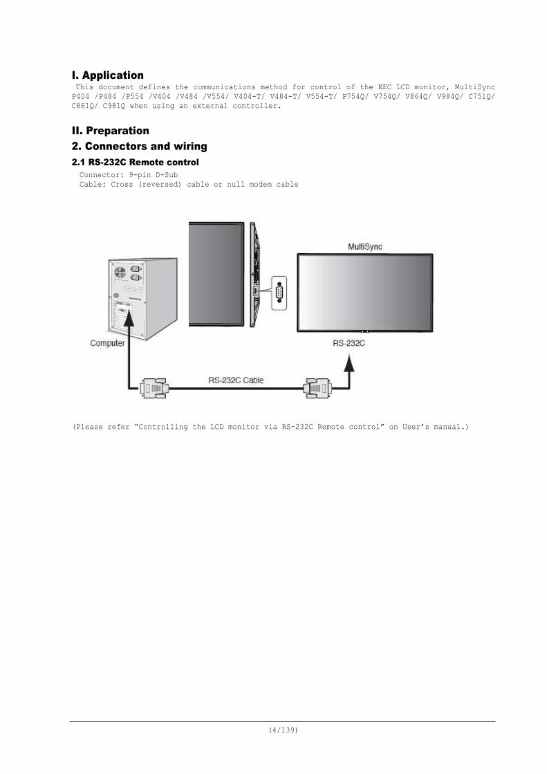
II. Preparation 2. Connectors and wiring 2.1 RS-232C Remote control Connector: 9-pin D-Sub Cable: Cross (reversed) cable or null modem cable
(Please refer “Controlling the LCD monitor via RS-232C Remote control” on User’s manual.)
(5/139)
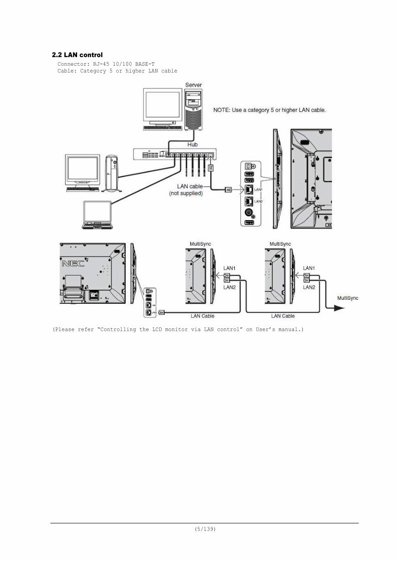
2.2 LAN control Connector: RJ-45 10/100 BASE-T Cable: Category 5 or higher LAN cable
(Please refer “Controlling the LCD monitor via LAN control” on User’s manual.)
(6/139)
III. Communication specification 3. Communication Parameter 3.1 RS-232C Remote control
(1) Communication system Asynchronous (2) Interface RS-232C (3) Baud rate 9600bps (4) Data length 8bits (5) Parity None (6) Stop bit 1 bit (7) Communication code ASCII
3.2 LAN control (1) Communication system TCP/IP (Internet protocol suite) (2) Interface Ethernet (CSMA/CD) (3) Communication layer Transport layer (TCP) * Using the payload of TCP segment. (4) IP address (Default) Automatic setup * If you need to change, Please refer “Network settings” on User’s manual. (5) Port No. 7142 (Fixed) (Note) The monitor will disconnect the connection if no packet data is received for 15 minutes. And the controller (PC) has to re-connect to control the monitor again, after 15 minutes or
more.
3.3 Communication timing The controller should wait for a reply packet before the next command is sent. (Note) When the following commands are sent, a controller should wait for specified period after receiving the reply command before sending the next command. Power On, Power Off: 15 seconds Input, PIP Input, Auto Setup, Factory Reset: 10 seconds
(7/139)
4. Communication Format
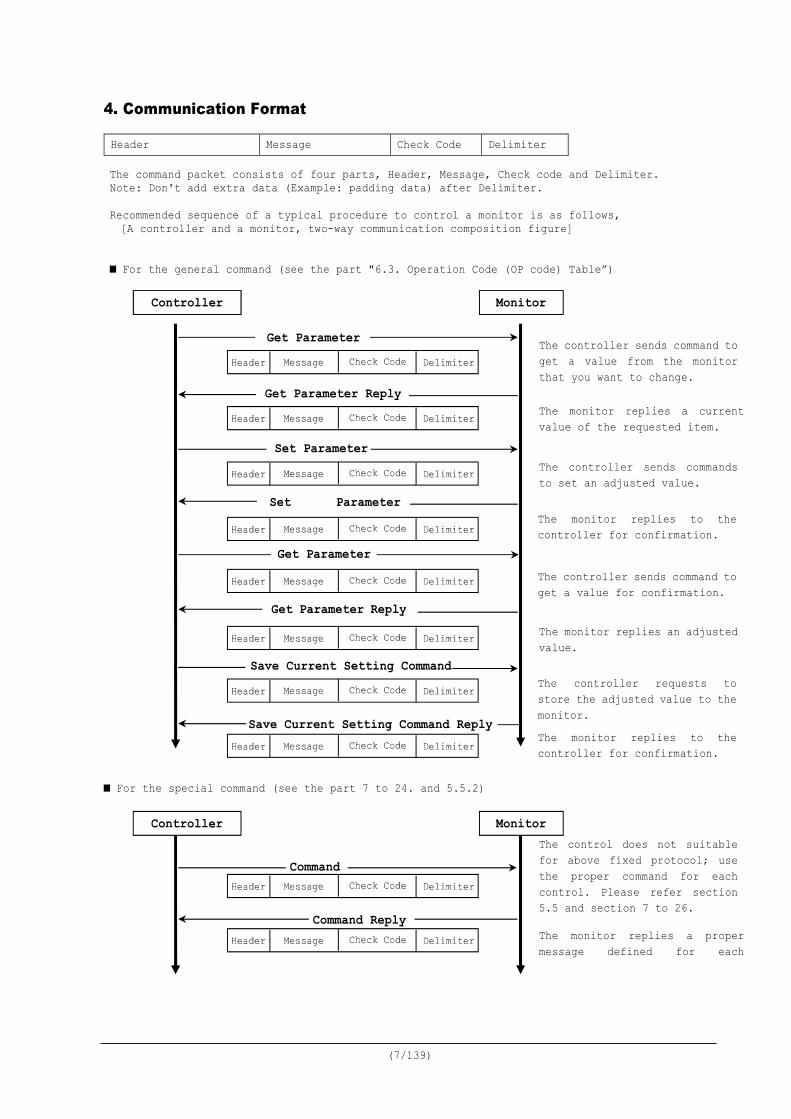
The command packet consists of four parts, Header, Message, Check code and Delimiter. Note: Don't add extra data (Example: padding data) after Delimiter. Recommended sequence of a typical procedure to control a monitor is as follows, [A controller and a monitor, two-way communication composition figure]
■ For the general command (see the part "6.3. Operation Code (OP code) Table”) ■ For the special command (see the part 7 to 24. and 5.5.2)
Header Message Check Code Delimiter
Monitor Controller
Get Parameter
Get Parameter Reply
Set Parameter
Set Parameter
Get Parameter Reply
Save Current Setting Command
Get Parameter
The controller sends command to get a value from the monitor that you want to change.
The monitor replies a current value of the requested item. The controller sends commands to set an adjusted value. The monitor replies to the controller for confirmation.
The controller sends command to get a value for confirmation.
The monitor replies an adjusted value.
The controller requests to store the adjusted value to the monitor.
Command
Command Reply
The control does not suitable for above fixed protocol; use the proper command for each control. Please refer section 5.5 and section 7 to 26.
The monitor replies a proper message defined for each
Save Current Setting Command Reply The monitor replies to the controller for confirmation.
Monitor Controller
(8/139)
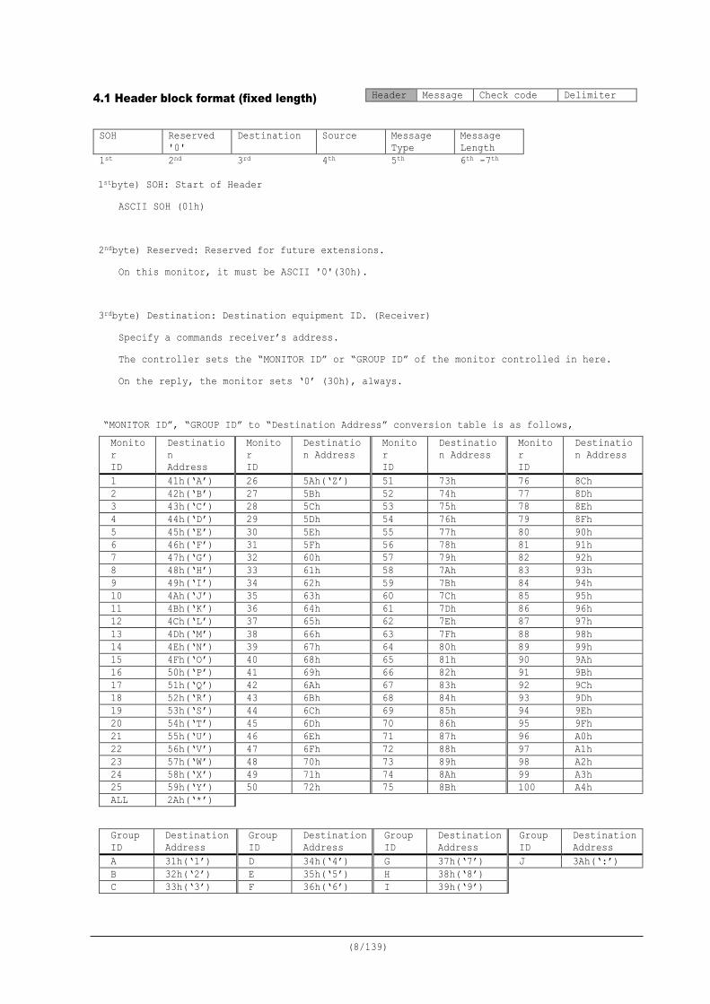
4.1 Header block format (fixed length)
1stbyte) SOH: Start of Header ASCII SOH (01h)
2ndbyte) Reserved: Reserved for future extensions.
On this monitor, it must be ASCII '0'(30h). 3rdbyte) Destination: Destination equipment ID. (Receiver)
Specify a commands receiver’s address. The controller sets the “MONITOR ID” or “GROUP ID” of the monitor controlled in here. On the reply, the monitor sets ‘0’ (30h), always.
“MONITOR ID”, “GROUP ID” to “Destination Address” conversion table is as follows, Monitor ID
Destination Address
Monitor ID
Destination Address
Monitor ID
Destination Address
Monitor ID
Destination Address
1 41h(‘A’) 26 5Ah(‘Z’) 51 73h 76 8Ch 2 42h(‘B’) 27 5Bh 52 74h 77 8Dh 3 43h(‘C’) 28 5Ch 53 75h 78 8Eh 4 44h(‘D’) 29 5Dh 54 76h 79 8Fh 5 45h(‘E’) 30 5Eh 55 77h 80 90h 6 46h(‘F’) 31 5Fh 56 78h 81 91h 7 47h(‘G’) 32 60h 57 79h 82 92h 8 48h(‘H’) 33 61h 58 7Ah 83 93h 9 49h(‘I’) 34 62h 59 7Bh 84 94h 10 4Ah(‘J’) 35 63h 60 7Ch 85 95h 11 4Bh(‘K’) 36 64h 61 7Dh 86 96h 12 4Ch(‘L’) 37 65h 62 7Eh 87 97h 13 4Dh(‘M’) 38 66h 63 7Fh 88 98h 14 4Eh(‘N’) 39 67h 64 80h 89 99h 15 4Fh(‘O’) 40 68h 65 81h 90 9Ah 16 50h(‘P’) 41 69h 66 82h 91 9Bh 17 51h(‘Q’) 42 6Ah 67 83h 92 9Ch 18 52h(‘R’) 43 6Bh 68 84h 93 9Dh 19 53h(‘S’) 44 6Ch 69 85h 94 9Eh 20 54h(‘T’) 45 6Dh 70 86h 95 9Fh 21 55h(‘U’) 46 6Eh 71 87h 96 A0h 22 56h(‘V’) 47 6Fh 72 88h 97 A1h 23 57h(‘W’) 48 70h 73 89h 98 A2h 24 58h(‘X’) 49 71h 74 8Ah 99 A3h 25 59h(‘Y’) 50 72h 75 8Bh 100 A4h ALL 2Ah(‘*’)
Group ID
Destination Address
Group ID
Destination Address
Group ID
Destination Address
Group ID
Destination Address
A 31h(‘1’) D 34h(‘4’) G 37h(‘7’) J 3Ah(‘:’) B 32h(‘2’) E 35h(‘5’) H 38h(‘8’) C 33h(‘3’) F 36h(‘6’) I 39h(‘9’)
Header Message Check code Delimiter
SOH Reserved '0'
Destination Source Message Type
Message Length
1st 2nd 3rd 4th 5th 6th -7th
(9/139)
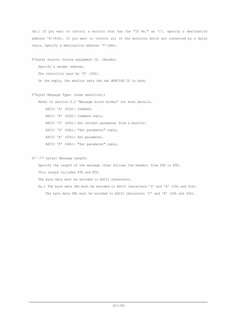
Ex.) If you want to control a monitor that has the "ID No." as '1', specify a destination address 'A'(41h). If you want to control all of the monitors which are connected by a daisy chain, specify a destination address ‘*’(2Ah). 4thbyte) Source: Source equipment ID. (Sender)
Specify a sender address. The controller must be ‘0’ (30h). On the reply, the monitor sets the own MONITOR ID in here.
5thbyte) Message Type: (Case sensitive.)
Refer to section 4.2 “Message block format” for more details. ASCII 'A' (41h): Command. ASCII 'B' (42h): Command reply. ASCII 'C' (43h): Get current parameter from a monitor.
ASCII 'D' (44h): "Get parameter" reply. ASCII 'E' (45h): Set parameter.
ASCII 'F' (46h): "Set parameter" reply. 6th -7th bytes) Message Length:
Specify the length of the message (that follows the header) from STX to ETX. This length includes STX and ETX. The byte data must be encoded to ASCII characters. Ex.) The byte data 3Ah must be encoded to ASCII characters '3' and 'A' (33h and 41h).
The byte data 0Bh must be encoded to ASCII characters '0' and 'B' (30h and 42h).
(10/139)
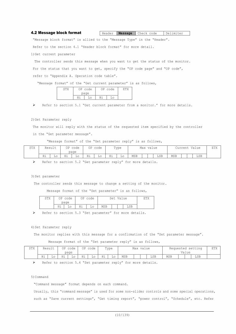
4.2 Message block format “Message block format” is allied to the “Message Type” in the “Header”. Refer to the section 4.1 “Header block format” for more detail. 1)Get current parameter The controller sends this message when you want to get the status of the monitor. For the status that you want to get, specify the “OP code page” and “OP code”, refer to “Appendix A. Operation code table”.
“Message format” of the “Get current parameter” is as follows,
Refer to section 5.1 “Get current parameter from a monitor.” for more details. 2)Get Parameter reply The monitor will reply with the status of the requested item specified by the controller in the “Get parameter message”.
“Message format” of the “Get parameter reply” is as follows,
Refer to section 5.2 “Get parameter reply” for more details.
3)Set parameter The controller sends this message to change a setting of the monitor.
Message format of the “Set parameter” is as follows,
Refer to section 5.3 “Set parameter” for more details.
4)Set Parameter reply The monitor replies with this message for a confirmation of the “Set parameter message”.
Message format of the “Set parameter reply” is as follows,
Refer to section 5.4 “Set parameter reply” for more details. 5)Command “Command message” format depends on each command. Usually, this “command message” is used for some non-slider controls and some special operations, such as “Save current settings”, “Get timing report”, “power control”, “Schedule”, etc. Refer
Header Message Check code Delimiter
STX OP code page
OP code ETX
Hi Lo Hi Lo
STX Result OP code page
OP code Type Max value Current Value ETX
Hi Lo Hi Lo Hi Lo Hi Lo MSB LSB MSB LSB
STX OP code page
OP code Set Value ETX
Hi Lo Hi Lo MSB LSB
STX Result OP code page
OP code Type Max value Requested setting Value
ETX
Hi Lo Hi Lo Hi Lo Hi Lo MSB LSB MSB LSB

(11/139)
to section 5.5 “Commands message” for more details.
6)Command reply The monitor replies to a query from the controller. “Command reply message” format depends on each command. Refer to section 5.5 “Commands message” for more details.
(12/139)
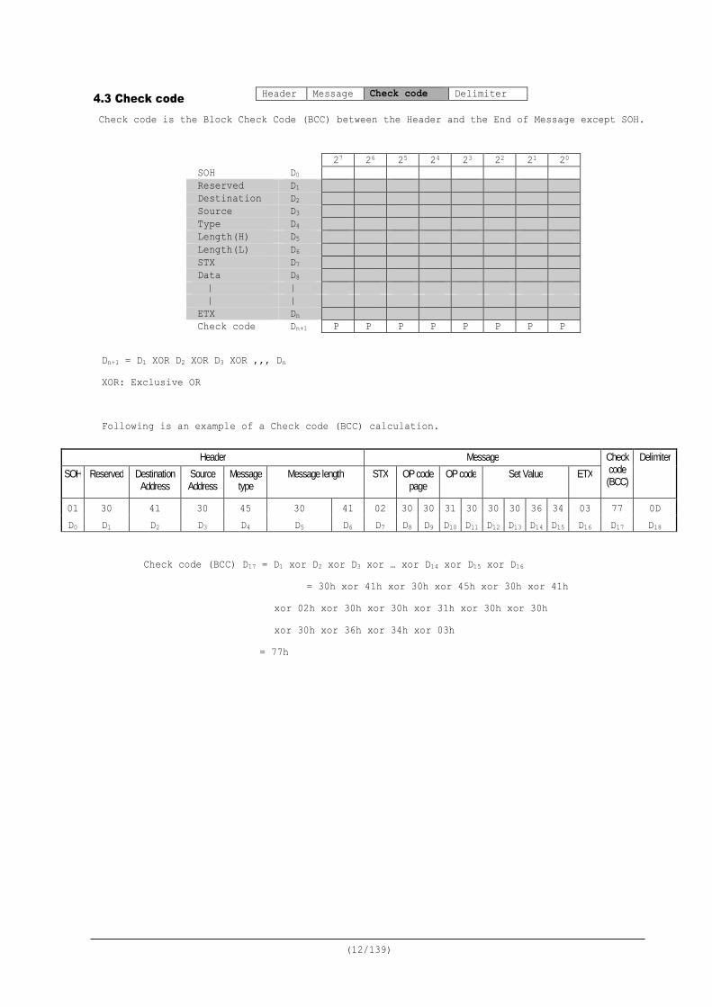
4.3 Check code Check code is the Block Check Code (BCC) between the Header and the End of Message except SOH.
Dn+1 = D1 XOR D2 XOR D3 XOR ,,, Dn XOR: Exclusive OR Following is an example of a Check code (BCC) calculation.
Check code (BCC) D17 = D1 xor D2 xor D3 xor … xor D14 xor D15 xor D16 = 30h xor 41h xor 30h xor 45h xor 30h xor 41h xor 02h xor 30h xor 30h xor 31h xor 30h xor 30h xor 30h xor 36h xor 34h xor 03h = 77h
Header Message Check code Delimiter
27 26 25 24 23 22 21 20 SOH D0 Reserved D1 Destination D2 Source D3 Type D4 Length(H) D5 Length(L) D6 STX D7 Data D8 | | | | ETX Dn Check code Dn+1 P P P P P P P P
Header Message Check code
(BCC)
Delimiter SOH Reserved Destination
Address Source Address
Message type
Message length STX OP code page
OP code Set Value ETX
01 30 41 30 45 30 41 02 30 30 31 30 30 30 36 34 03 77 0D D0 D1 D2 D3 D4 D5 D6 D7 D8 D9 D10 D11 D12 D13 D14 D15 D16 D17 D18

(13/139)
4.4 Delimiter Packet delimiter code; ASCII CR(0Dh).
Header Message Check code Delimiter
(14/139)
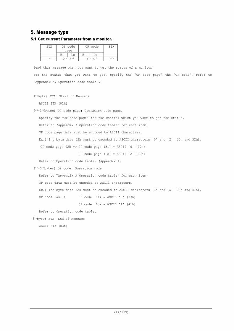
5. Message type 5.1 Get current Parameter from a monitor.
Send this message when you want to get the status of a monitor. For the status that you want to get, specify the “OP code page” the “OP code”, refer to “Appendix A. Operation code table”. 1stbyte) STX: Start of Message
ASCII STX (02h) 2nd-3rdbytes) OP code page: Operation code page.
Specify the “OP code page” for the control which you want to get the status. Refer to “Appendix A Operation code table” for each item. OP code page data must be encoded to ASCII characters. Ex.) The byte data 02h must be encoded to ASCII characters '0' and '2' (30h and 32h). OP code page 02h -> OP code page (Hi) = ASCII '0' (30h) OP code page (Lo) = ASCII '2' (32h) Refer to Operation code table. (Appendix A)
4th–5thbytes) OP code: Operation code Refer to “Appendix A Operation code table” for each item. OP code data must be encoded to ASCII characters. Ex.) The byte data 3Ah must be encoded to ASCII characters '3' and 'A' (33h and 41h). OP code 3Ah -> OP code (Hi) = ASCII '3' (33h) OP code (Lo) = ASCII 'A' (41h) Refer to Operation code table.
6thbyte) ETX: End of Message ASCII ETX (03h)
STX OP code page
OP code ETX
Hi Lo Hi Lo 1st 2nd-3rd 4th–5th 6th
(15/139)
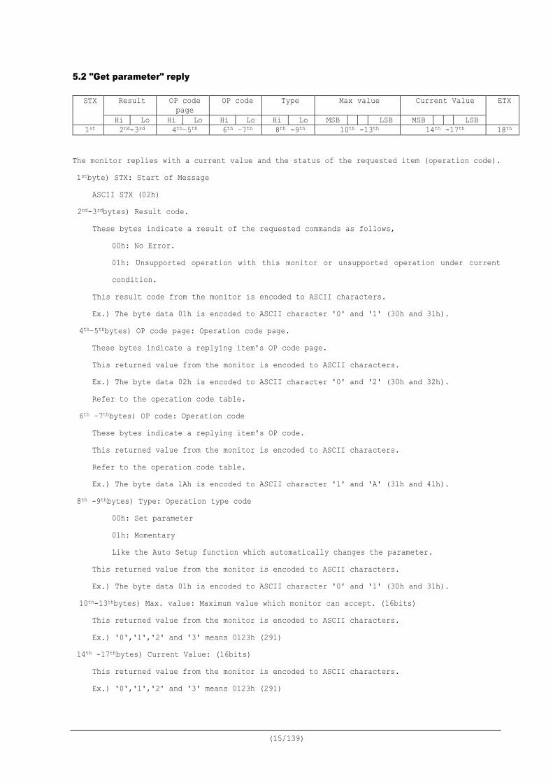
5.2 "Get parameter" reply
The monitor replies with a current value and the status of the requested item (operation code). 1stbyte) STX: Start of Message
ASCII STX (02h) 2nd-3rdbytes) Result code.
These bytes indicate a result of the requested commands as follows, 00h: No Error. 01h: Unsupported operation with this monitor or unsupported operation under current condition.
This result code from the monitor is encoded to ASCII characters. Ex.) The byte data 01h is encoded to ASCII character '0' and '1' (30h and 31h).
4th–5thbytes) OP code page: Operation code page. These bytes indicate a replying item's OP code page. This returned value from the monitor is encoded to ASCII characters. Ex.) The byte data 02h is encoded to ASCII character '0' and '2' (30h and 32h). Refer to the operation code table.
6th –7thbytes) OP code: Operation code These bytes indicate a replying item's OP code. This returned value from the monitor is encoded to ASCII characters. Refer to the operation code table. Ex.) The byte data 1Ah is encoded to ASCII character '1' and 'A' (31h and 41h).
8th -9thbytes) Type: Operation type code 00h: Set parameter 01h: Momentary Like the Auto Setup function which automatically changes the parameter.
This returned value from the monitor is encoded to ASCII characters. Ex.) The byte data 01h is encoded to ASCII character '0' and '1' (30h and 31h).
10th-13thbytes) Max. value: Maximum value which monitor can accept. (16bits) This returned value from the monitor is encoded to ASCII characters. Ex.) '0','1','2' and '3' means 0123h (291)
14th -17thbytes) Current Value: (16bits) This returned value from the monitor is encoded to ASCII characters. Ex.) '0','1','2' and '3' means 0123h (291)
STX Result OP code page
OP code Type Max value Current Value ETX
Hi Lo Hi Lo Hi Lo Hi Lo MSB LSB MSB LSB 1st 2nd-3rd 4th–5th 6th –7th 8th -9th 10th -13th 14th -17th 18th

(16/139)
18thbyte) ETX: End of Message ASCII ETX (03h)
(17/139)
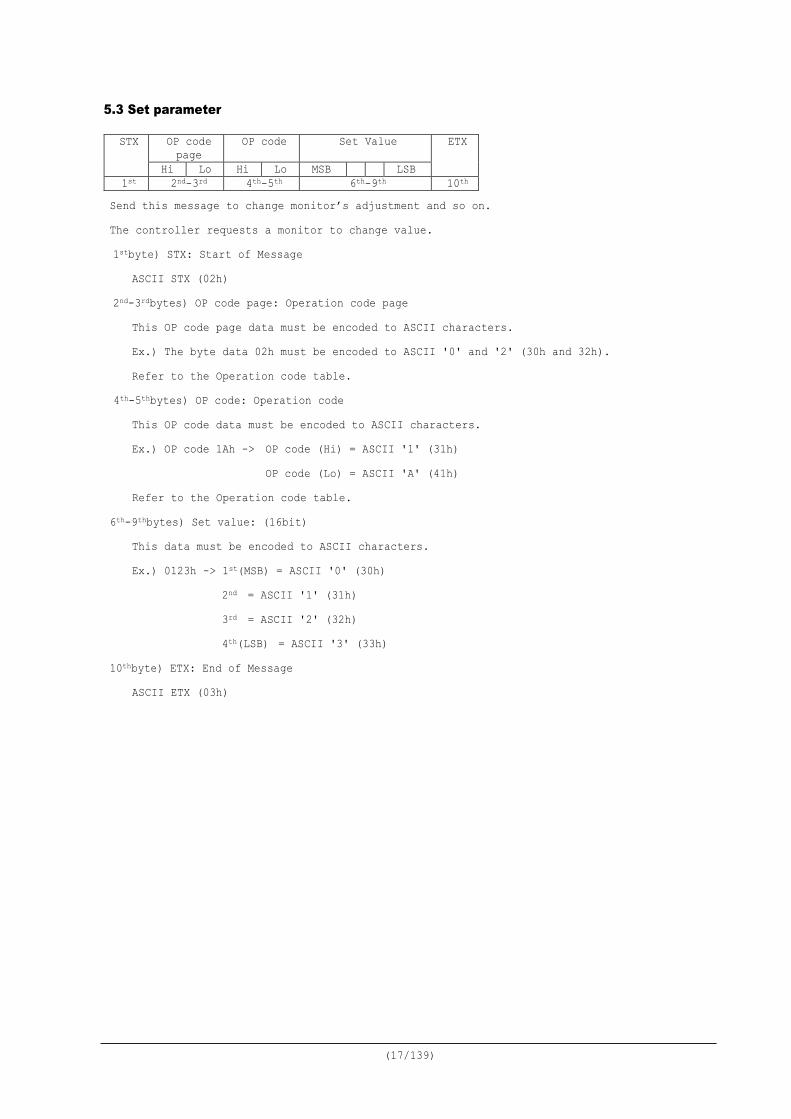
5.3 Set parameter
Send this message to change monitor’s adjustment and so on. The controller requests a monitor to change value. 1stbyte) STX: Start of Message
ASCII STX (02h) 2nd-3rdbytes) OP code page: Operation code page
This OP code page data must be encoded to ASCII characters. Ex.) The byte data 02h must be encoded to ASCII '0' and '2' (30h and 32h). Refer to the Operation code table.
4th-5thbytes) OP code: Operation code This OP code data must be encoded to ASCII characters. Ex.) OP code 1Ah -> OP code (Hi) = ASCII '1' (31h) OP code (Lo) = ASCII 'A' (41h) Refer to the Operation code table.
6th-9thbytes) Set value: (16bit) This data must be encoded to ASCII characters. Ex.) 0123h -> 1st(MSB) = ASCII '0' (30h)
2nd = ASCII '1' (31h) 3rd = ASCII '2' (32h) 4th(LSB) = ASCII '3' (33h)
10thbyte) ETX: End of Message ASCII ETX (03h)
STX OP code page
OP code Set Value ETX
Hi Lo Hi Lo MSB LSB 1st 2nd-3rd 4th-5th 6th-9th 10th
(18/139)
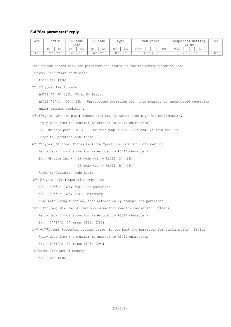
5.4 "Set parameter" reply
The Monitor echoes back the parameter and status of the requested operation code. 1stbyte) STX: Start of Message
ASCII STX (02h) 2nd-3rdbytes) Result code
ASCII '0''0' (30h, 30h): No Error. ASCII '0''1' (30h, 31h): Unsupported operation with this monitor or unsupported operation under current condition.
4th-5thbytes) OP code page: Echoes back the Operation code page for confirmation. Reply data from the monitor is encoded to ASCII characters. Ex.) OP code page 02h -> OP code page = ASCII '0' and '2' (30h and 32h) Refer to Operation code table.
6th-7thbytes) OP code: Echoes back the Operation code for confirmation. Reply data from the monitor is encoded to ASCII characters. Ex.) OP code 1Ah -> OP code (Hi) = ASCII '1' (31h) OP code (Lo) = ASCII 'A' (41h) Refer to Operation code table
8th-9thbytes) Type: Operation type code ASCII '0''0' (30h, 30h): Set parameter ASCII '0''1' (30h, 31h): Momentary Like Auto Setup function, that automatically changes the parameter.
10th-13thbytes) Max. value: Maximum value that monitor can accept. (16bits) Reply data from the monitor is encoded to ASCII characters. Ex.) '0''1''2''3' means 0123h (291)
14th -17thbytes) Requested setting Value: Echoes back the parameter for confirmation. (16bits) Reply data from the monitor is encoded to ASCII characters. Ex.) '0''1''2''3' means 0123h (291)
18thbyte) ETX: End of Message ASCII ETX (03h)
STX Result OP code page
OP code Type Max value Requested setting Value
ETX
Hi Lo Hi Lo Hi Lo Hi Lo MSB LSB MSB LSB 1st 2nd-3rd 4th-5th 6th-7th 8th-9th 10th-13th 14th -17th 18th
(19/139)
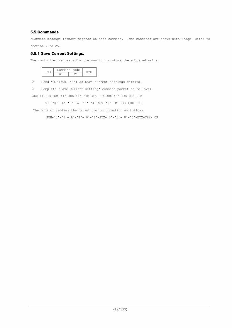
5.5 Commands "Command message format" depends on each command. Some commands are shown with usage. Refer to section 7 to 25.
5.5.1 Save Current Settings. The controller requests for the monitor to store the adjusted value.
Send "OC"(30h, 43h) as Save current settings command. Complete "Save Current setting" command packet as follows; ASCII: 01h-30h-41h-30h-41h-30h-34h-02h-30h-43h-03h-CHK-0Dh
SOH-'0'-'A'-'0'-'A'-'0'-'4'-STX-'0'-'C'-ETX-CHK- CR The monitor replies the packet for confirmation as follows; SOH-'0'-'0'-'A'-'B'-'0'-'6'-STX-'0'-'0'-'0'-'C'-ETX-CHK- CR
STX Command code ETX '0' 'C'
(20/139)
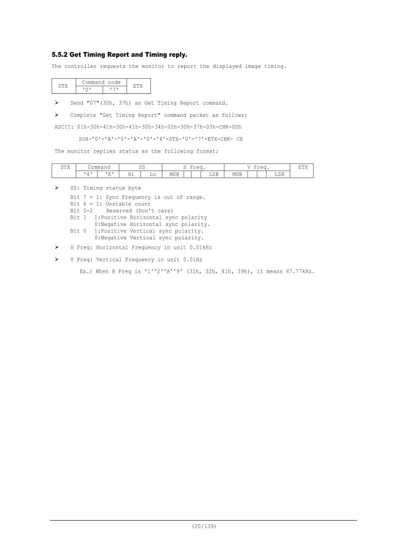
5.5.2 Get Timing Report and Timing reply. The controller requests the monitor to report the displayed image timing.
Send "07"(30h, 37h) as Get Timing Report command. Complete "Get Timing Report" command packet as follows; ASCII: 01h-30h-41h-30h-41h-30h-34h-02h-30h-37h-03h-CHK-0Dh
SOH-'0'-'A'-'0'-'A'-'0'-'4'-STX-'0'-'7'-ETX-CHK- CR The monitor replies status as the following format;
SS: Timing status byte Bit 7 = 1: Sync Frequency is out of range. Bit 6 = 1: Unstable count Bit 5-2 Reserved (Don't care) Bit 1 1:Positive Horizontal sync polarity
0:Negative Horizontal sync polarity. Bit 0 1:Positive Vertical sync polarity.
0:Negative Vertical sync polarity. H Freq: Horizontal Frequency in unit 0.01kHz V Freq: Vertical Frequency in unit 0.01Hz
Ex.) When H Freq is '1''2''A''9' (31h, 32h, 41h, 39h), it means 47.77kHz.
STX Command code ETX '0' '7'
STX Command SS H Freq. V Freq. ETX '4' 'E' Hi Lo MSB LSB MSB LSB
(21/139)
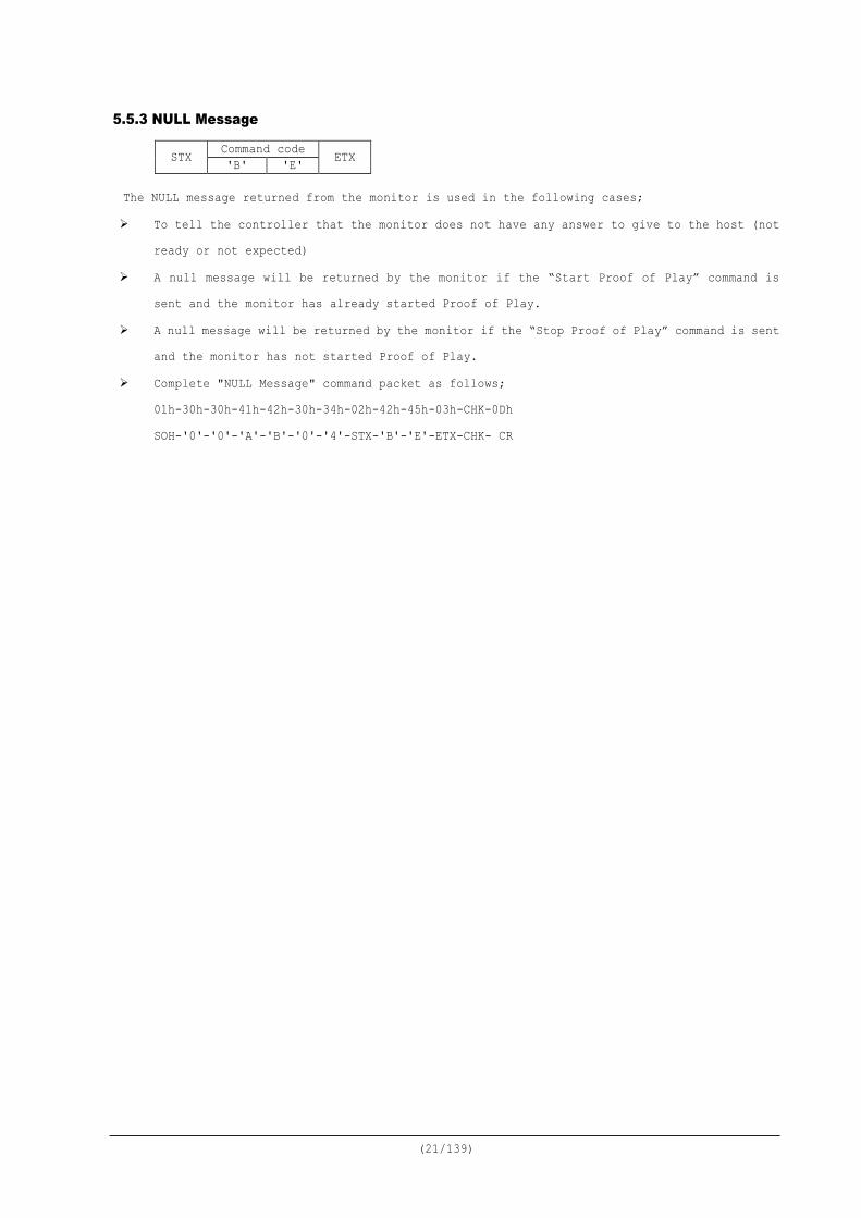
5.5.3 NULL Message
The NULL message returned from the monitor is used in the following cases;
To tell the controller that the monitor does not have any answer to give to the host (not ready or not expected)
A null message will be returned by the monitor if the “Start Proof of Play” command is sent and the monitor has already started Proof of Play.
A null message will be returned by the monitor if the “Stop Proof of Play” command is sent and the monitor has not started Proof of Play.
Complete "NULL Message" command packet as follows; 01h-30h-30h-41h-42h-30h-34h-02h-42h-45h-03h-CHK-0Dh SOH-'0'-'0'-'A'-'B'-'0'-'4'-STX-'B'-'E'-ETX-CHK- CR
STX Command code ETX 'B' 'E'
(22/139)
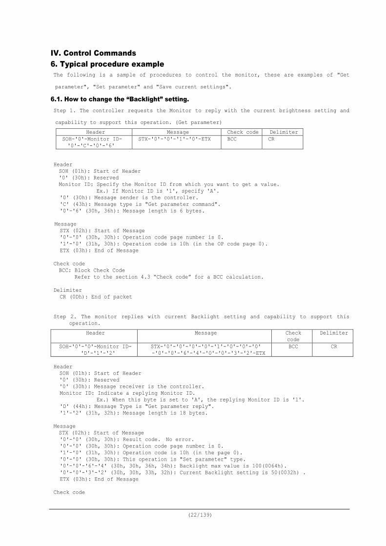
IV. Control Commands 6. Typical procedure example The following is a sample of procedures to control the monitor, these are examples of "Get parameter", "Set parameter" and "Save current settings".
6.1. How to change the “Backlight” setting. Step 1. The controller requests the Monitor to reply with the current brightness setting and capability to support this operation. (Get parameter)
Header Message Check code Delimiter SOH-'0'-Monitor ID- '0'-'C'-'0'-'6'
STX-'0'-'0'-'1'-'0'-ETX BCC CR
Header SOH (01h): Start of Header '0' (30h): Reserved Monitor ID: Specify the Monitor ID from which you want to get a value.
Ex.) If Monitor ID is '1', specify 'A'. '0' (30h): Message sender is the controller. 'C' (43h): Message type is "Get parameter command". '0'-'6' (30h, 36h): Message length is 6 bytes.
Message STX (02h): Start of Message '0'-'0' (30h, 30h): Operation code page number is 0. '1'-'0' (31h, 30h): Operation code is 10h (in the OP code page 0). ETX (03h): End of Message
Check code BCC: Block Check Code Refer to the section 4.3 “Check code” for a BCC calculation.
Delimiter
CR (0Dh): End of packet Step 2. The monitor replies with current Backlight setting and capability to support this
operation.
Header SOH (01h): Start of Header '0' (30h): Reserved '0' (30h): Message receiver is the controller. Monitor ID: Indicate a replying Monitor ID.
Ex.) When this byte is set to 'A', the replying Monitor ID is '1'. 'D' (44h): Message Type is "Get parameter reply". '1'-'2' (31h, 32h): Message length is 18 bytes.
Message STX (02h): Start of Message '0'-'0' (30h, 30h): Result code. No error. '0'-'0' (30h, 30h): Operation code page number is 0. '1'-'0' (31h, 30h): Operation code is 10h (in the page 0). '0'-'0' (30h, 30h): This operation is "Set parameter" type. '0'-'0'-'6'-'4' (30h, 30h, 36h, 34h): Backlight max value is 100(0064h). '0'-'0'-'3'-'2' (30h, 30h, 33h, 32h): Current Backlight setting is 50(0032h) . ETX (03h): End of Message
Check code
Header Message Check code
Delimiter
SOH-'0'-'0'-Monitor ID- 'D'-'1'-'2'
STX-'0'-'0'-'0'-'0'-'1'-'0'-'0'-'0' -'0'-'0'-'6'-'4'-'0'-'0'-'3'-'2'-ETX
BCC CR
(23/139)
BCC: Block Check Code Refer to the section 4.3 “Check code” for a BCC calculation.
Delimiter
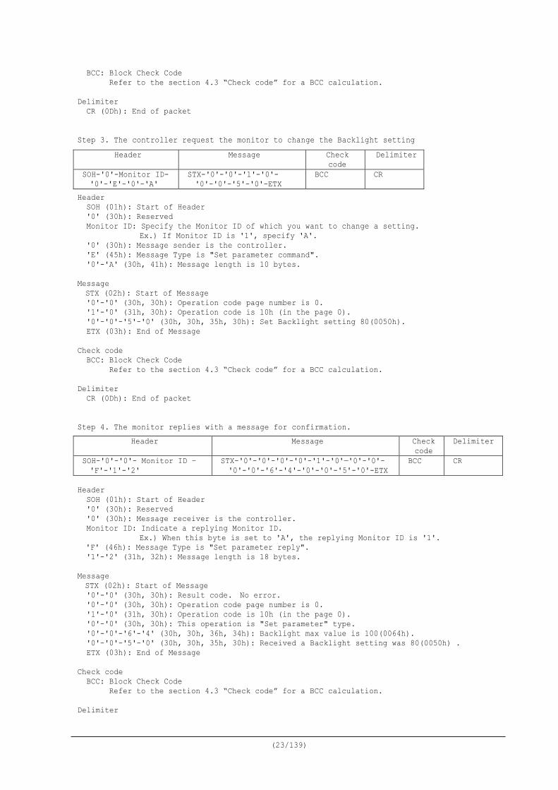
CR (0Dh): End of packet Step 3. The controller request the monitor to change the Backlight setting
Header SOH (01h): Start of Header '0' (30h): Reserved Monitor ID: Specify the Monitor ID of which you want to change a setting.
Ex.) If Monitor ID is '1', specify 'A'. '0' (30h): Message sender is the controller. 'E' (45h): Message Type is "Set parameter command". '0'-'A' (30h, 41h): Message length is 10 bytes.
Message STX (02h): Start of Message '0'-'0' (30h, 30h): Operation code page number is 0. '1'-'0' (31h, 30h): Operation code is 10h (in the page 0). '0'-'0'-'5'-'0' (30h, 30h, 35h, 30h): Set Backlight setting 80(0050h). ETX (03h): End of Message
Check code
BCC: Block Check Code Refer to the section 4.3 “Check code” for a BCC calculation.
Delimiter
CR (0Dh): End of packet Step 4. The monitor replies with a message for confirmation.
Header
SOH (01h): Start of Header '0' (30h): Reserved '0' (30h): Message receiver is the controller. Monitor ID: Indicate a replying Monitor ID.
Ex.) When this byte is set to 'A', the replying Monitor ID is '1'. 'F' (46h): Message Type is "Set parameter reply". '1'-'2' (31h, 32h): Message length is 18 bytes.
Message STX (02h): Start of Message '0'-'0' (30h, 30h): Result code. No error. '0'-'0' (30h, 30h): Operation code page number is 0. '1'-'0' (31h, 30h): Operation code is 10h (in the page 0). '0'-'0' (30h, 30h): This operation is "Set parameter" type. '0'-'0'-'6'-'4' (30h, 30h, 36h, 34h): Backlight max value is 100(0064h). '0'-'0'-'5'-'0' (30h, 30h, 35h, 30h): Received a Backlight setting was 80(0050h) . ETX (03h): End of Message
Check code BCC: Block Check Code Refer to the section 4.3 “Check code” for a BCC calculation.
Delimiter
Header Message Check code
Delimiter
SOH-'0'-Monitor ID- '0'-'E'-'0'-'A'
STX-'0'-'0'-'1'-'0'- '0'-'0'-'5'-'0'-ETX
BCC CR
Header Message Check code
Delimiter
SOH-'0'-'0'- Monitor ID – 'F'-'1'-'2'
STX-'0'-'0'-'0'-'0'-'1'-'0'—'0'-'0'- '0'-'0'-'6'-'4'-'0'-'0'-'5'-'0'-ETX
BCC CR
(24/139)
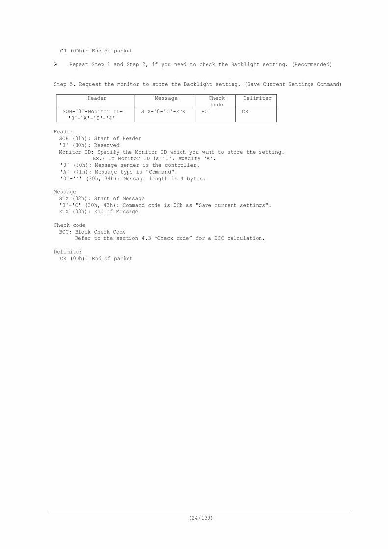
CR (0Dh): End of packet Repeat Step 1 and Step 2, if you need to check the Backlight setting. (Recommended) Step 5. Request the monitor to store the Backlight setting. (Save Current Settings Command)
Header Message Check code
Delimiter
SOH-'0'-Monitor ID- '0'-'A'-'0'-'4'
STX-'0-'C'-ETX BCC CR
Header SOH (01h): Start of Header '0' (30h): Reserved Monitor ID: Specify the Monitor ID which you want to store the setting.
Ex.) If Monitor ID is '1', specify 'A'. '0' (30h): Message sender is the controller. 'A' (41h): Message type is "Command". '0'-'4' (30h, 34h): Message length is 4 bytes.
Message STX (02h): Start of Message '0'-'C' (30h, 43h): Command code is 0Ch as "Save current settings". ETX (03h): End of Message
Check code BCC: Block Check Code Refer to the section 4.3 “Check code” for a BCC calculation.
Delimiter
CR (0Dh): End of packet
(25/139)
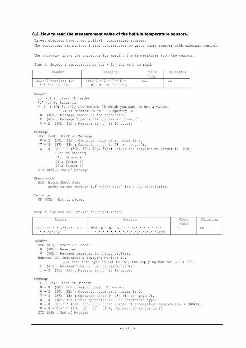
6.2. How to read the measurement value of the built-in temperature sensors. Target displays have three built-in temperature sensors. The controller can monitor inside temperatures by using those sensors with external control. The following shows the procedure for reading the temperatures from the sensors. Step 1. Select a temperature sensor which you want to read.
Header SOH (01h): Start of Header '0' (30h): Reserved Monitor ID: Specify the Monitor ID which you want to get a value.
Ex.) If Monitor ID is '1', specify 'A'. '0' (30h): Message sender is the controller. 'E' (45h): Message Type is "Set parameter command". '0'-'A' (30h, 41h): Message length is 10 bytes.
Message STX (02h): Start of Message '0'-'2' (30h, 32h): Operation code page number is 2. '7'-'8' (37h, 38h): Operation code is 78h (on page 2). '0'-'0'-'0'-'1' (30h, 30h, 30h, 31h): Select the temperature sensor #1 (01h).
00h: No meaning 01h: Sensor #1 02h: Sensor #2 03h: Sensor #3
ETX (03h): End of Message Check code
BCC: Block Check Code Refer to the section 4.3 “Check code” for a BCC calculation.
Delimiter
CR (0Dh): End of packet
Step 2. The monitor replies for confirmation.
Header SOH (01h): Start of Header '0' (30h): Reserved '0' (30h): Message receiver is the controller. Monitor ID: Indicates a replying Monitor ID.
Ex.) When this byte is set to 'A', the replying Monitor ID is '1'. 'F' (46h): Message Type is "Set parameter reply". '1'-'2' (31h, 32h): Message length is 18 bytes.
Message STX (02h): Start of Message '0'-'0' (30h, 30h): Result code. No error. '0'-'2' (30h, 32h): Operation code page number is 2. '7'-'8' (37h, 38h): Operation code is 78h (in the page 2). '0'-'0' (30h, 30h): This operation is "Set parameter" type. '0'-'0'-'0'-'3' (30h, 30h, 30h, 33h): Number of temperature sensors are 3 (0003h). '0'-'0'-'0'-'1' (30h, 30h, 30h, 31h): temperature sensor is #1. ETX (03h): End of Message
Header Message Check code
Delimiter
SOH-'0'-Monitor ID- '0'-'E'-'0'-'A'
STX-'0'-'2'-'7'-'8'- '0'-'0'-'0'-'1'-ETX
BCC CR
Header Message Check code
Delimiter
SOH-'0'-'0'-Monitor ID- 'F'-'1'-'2'
STX-'0'-'0'-'0'-'2'-'7'-'8'-'0'-'0'- '0'-'0'-'0'-'3'-'0'-'0'-'0'-'1'-ETX
BCC CR
(26/139)
Check code
BCC: Block Check Code Refer to the section 4.3 “Check code” for a BCC calculation.
Delimiter CR (0Dh): End of packet
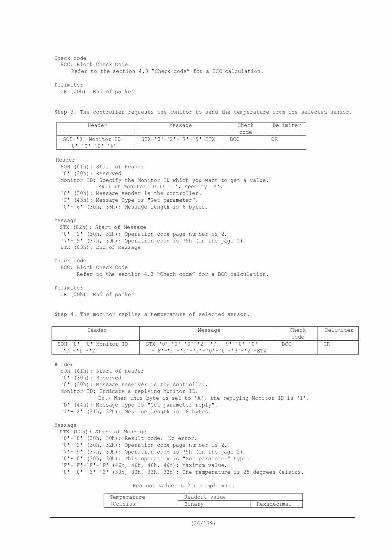
Step 3. The controller requests the monitor to send the temperature from the selected sensor.
Header Message Check code
Delimiter
SOH-'0'-Monitor ID- '0'-'C'-'0'-'6'
STX-'0'-'2'-'7'-'9'-ETX BCC CR
Header SOH (01h): Start of Header '0' (30h): Reserved Monitor ID: Specify the Monitor ID which you want to get a value.
Ex.) If Monitor ID is '1', specify 'A'. '0' (30h): Message sender is the controller. 'C' (43h): Message Type is "Get parameter". '0'-'6' (30h, 36h): Message length is 6 bytes.
Message STX (02h): Start of Message '0'-'2' (30h, 32h): Operation code page number is 2. '7'-'9' (37h, 39h): Operation code is 79h (in the page 2). ETX (03h): End of Message
Check code
BCC: Block Check Code Refer to the section 4.3 “Check code” for a BCC calculation.
Delimiter CR (0Dh): End of packet
Step 4. The monitor replies a temperature of selected sensor.
Header
SOH (01h): Start of Header '0' (30h): Reserved '0' (30h): Message receiver is the controller. Monitor ID: Indicate a replying Monitor ID.
Ex.) When this byte is set to 'A', the replying Monitor ID is '1'. 'D' (44h): Message Type is "Get parameter reply". '1'-'2' (31h, 32h): Message length is 18 bytes.
Message STX (02h): Start of Message '0'-'0' (30h, 30h): Result code. No error. '0'-'2' (30h, 32h): Operation code page number is 2. '7'-'9' (37h, 39h): Operation code is 79h (in the page 2). '0'-'0' (30h, 30h): This operation is "Set parameter" type. 'F'-'F'-'F'-'F' (46h, 46h, 46h, 46h): Maximum value. '0'-'0'-'3'-'2' (30h, 30h, 33h, 32h): The temperature is 25 degrees Celsius.
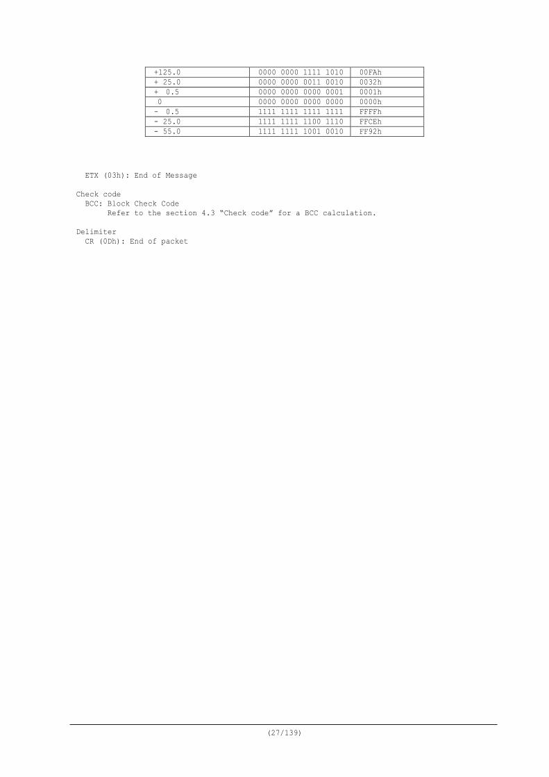
Readout value is 2's complement.
Header Message Check code
Delimiter
SOH-'0'-'0'-Monitor ID- 'D'-'1'-'2'
STX-'0'-'0'-'0'-'2'-'7'-'9'-'0'-'0' -'F'-'F'-'F'-'F'-'0'-'0'-'3'-'2'-ETX
BCC CR
Temperature [Celsius]
Readout value Binary Hexadecimal
(27/139)
ETX (03h): End of Message
Check code BCC: Block Check Code Refer to the section 4.3 “Check code” for a BCC calculation.
Delimiter
CR (0Dh): End of packet
+125.0 0000 0000 1111 1010 00FAh + 25.0 0000 0000 0011 0010 0032h + 0.5 0000 0000 0000 0001 0001h 0 0000 0000 0000 0000 0000h - 0.5 1111 1111 1111 1111 FFFFh - 25.0 1111 1111 1100 1110 FFCEh - 55.0 1111 1111 1001 0010 FF92h
(28/139)
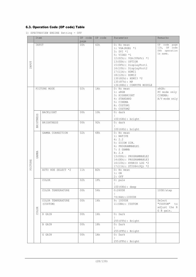
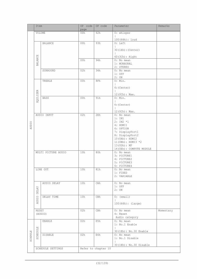
6.3. Operation Code (OP code) Table 1) SPECTRAVIEW ENGINE Setting = OFF
Item OP code page
OP code Parameter Remarks
INPU
T
INPUT 00h 60h 0: No mean 1: VGA(RGB) *1 3: DVI *1 5: VIDEO *1 12(0Ch): YGA(YPbPr) *1 13(0Dh): OPTION 15(0Fh): DisplayPort1 16(10h): DisplayPort2 17(11h): HDMI1 18(12h): HDMI2 130(82h): HDMI3 *2 135(87h): MP 136(88h): COMPUTE MODULE
OP code page 11h, OP code 06h operation is same.
PICT
URE
PICTURE MODE 02h 1Ah 0: No mean 1: sRGB 3: HIGHBRIGHT 4: STANDARD 5: CINEMA 8: CUSTOM1 9: CUSTOM2
sRGB: PC mode only CINEMA: A/V mode only
BRIG
TNES
S BACKLIGHT 00h 10h 0: dark | 100(64h): bright
BRIGHTNESS 00h 92h 0: dark | 100(64h): bright
GAMM
A
GAMMA CORRECTION 02h 68h 0: No mean 1: NATIVE 4: 2.2 5: DICOM SIM. 6: PROGRAMMABLE1 7: S GAMMA 8: 2.4 13(0Dh): PROGRAMMABLE2 14(0Eh): PROGRAMMABLE3 16(10h): HYBRID LOG *2 17(11h): ST2084(PQ) *2
AUTO HDE SELECT *2 11h B2h 0: No mean 1: ON 2: OFF
COLO
R
COLOR 02h 1Fh 0: pale | 100(64h): deep
COLOR TEMPERATURE 00h 54h 0:2600K | 74(4Ah):10000K
100K/step
COLOR TEMPERATURE (CUSTOM)
00h 14h 9: 10000K 11(0Bh): CUSTOM
Select "CUSTOM" to adjust the R G B gain.
R GAIN 00h 16h 0: Dark | 255(FFh): Bright
B GAIN 00h 18h 0: Dark | 255(FFh): Bright
G GAIN 00h 1Ah 0: Dark | 255(FFh): Bright
(29/139)
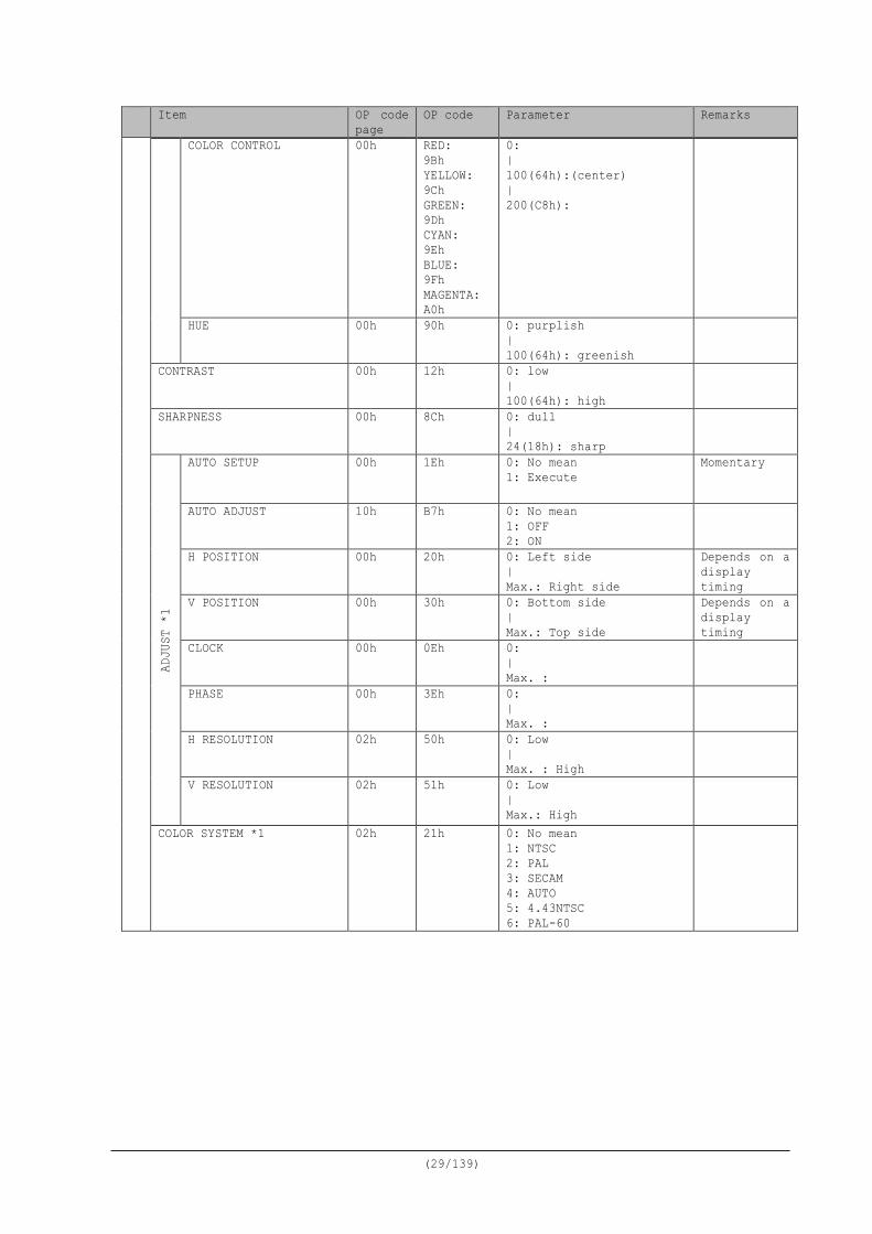
Item OP code page
OP code Parameter Remarks
COLOR CONTROL 00h RED: 9Bh YELLOW: 9Ch GREEN: 9Dh CYAN: 9Eh BLUE: 9Fh MAGENTA: A0h
0: | 100(64h):(center) | 200(C8h):
HUE 00h 90h 0: purplish | 100(64h): greenish
CONTRAST 00h 12h 0: low | 100(64h): high
SHARPNESS 00h 8Ch 0: dull | 24(18h): sharp
ADJU
ST *
1
AUTO SETUP 00h 1Eh 0: No mean 1: Execute
Momentary
AUTO ADJUST 10h B7h 0: No mean 1: OFF 2: ON
H POSITION 00h 20h 0: Left side | Max.: Right side
Depends on a display timing
V POSITION 00h 30h 0: Bottom side | Max.: Top side
Depends on a display timing
CLOCK 00h 0Eh 0: | Max. :
PHASE 00h 3Eh 0: | Max. :
H RESOLUTION 02h 50h 0: Low | Max. : High
V RESOLUTION 02h 51h 0: Low | Max.: High
COLOR SYSTEM *1 02h 21h 0: No mean 1: NTSC 2: PAL 3: SECAM 4: AUTO 5: 4.43NTSC 6: PAL-60
(30/139)
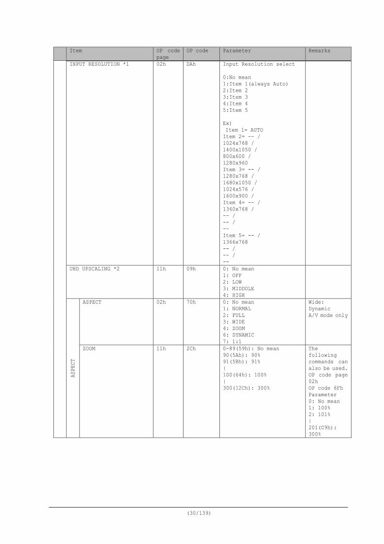
Item OP code page
OP code Parameter Remarks
INPUT RESOLUTION *1 02h DAh Input Resolution select 0:No mean 1:Item 1(always Auto) 2:Item 2 3:Item 3 4:Item 4 5:Item 5 Ex) Item 1= AUTO Item 2= -- / 1024x768 / 1400x1050 / 800x600 / 1280x960 Item 3= -- / 1280x768 / 1680x1050 / 1024x576 / 1600x900 / Item 4= -- / 1360x768 / -- / -- / -- Item 5= -- / 1366x768 -- / -- / --
UHD UPSCALING *2 11h 09h 0: No mean 1: OFF 2: LOW 3: MIDDOLE 4: HIGH
ASPE
CT
ASPECT 02h 70h 0: No mean 1: NORMAL 2: FULL 3: WIDE 4: ZOOM 6: DYNAMIC 7: 1:1
Wide: Dynamic A/V mode only
ZOOM 11h 2Ch 0-89(59h): No mean 90(5Ah): 90% 91(5Bh): 91% | 100(64h): 100% | 300(12Ch): 300%
The following commands can also be used. OP code page 02h OP code 6Fh Parameter 0: No mean 1: 100% 2: 101% | 201(C9h): 300%
(31/139)
Item OP code page
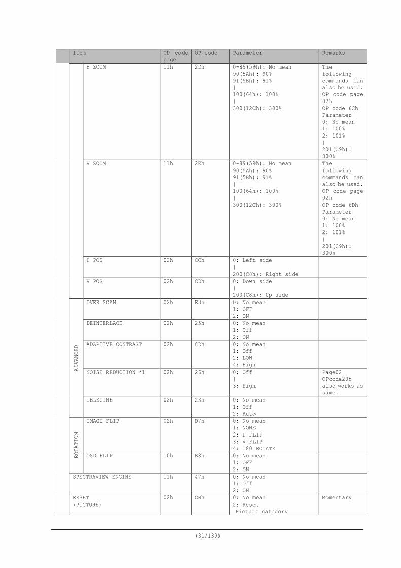
OP code Parameter Remarks
H ZOOM 11h 2Dh 0-89(59h): No mean 90(5Ah): 90% 91(5Bh): 91% | 100(64h): 100% | 300(12Ch): 300%
The following commands can also be used. OP code page 02h OP code 6Ch Parameter 0: No mean 1: 100% 2: 101% | 201(C9h): 300%
V ZOOM 11h 2Eh 0-89(59h): No mean 90(5Ah): 90% 91(5Bh): 91% | 100(64h): 100% | 300(12Ch): 300%
The following commands can also be used. OP code page 02h OP code 6Dh Parameter 0: No mean 1: 100% 2: 101% | 201(C9h): 300%
H POS 02h CCh 0: Left side | 200(C8h): Right side
V POS 02h CDh 0: Down side | 200(C8h): Up side
ADVA
NCED
OVER SCAN 02h E3h 0: No mean 1: OFF 2: ON
DEINTERLACE 02h 25h 0: No mean 1: Off 2: ON
ADAPTIVE CONTRAST 02h 8Dh 0: No mean 1: Off 2: LOW 4: High
NOISE REDUCTION *1 02h 26h 0: Off | 3: High
Page02 OPcode20h also works as same.
TELECINE 02h 23h 0: No mean 1: Off 2: Auto
ROTA
TION
IMAGE FLIP 02h D7h 0: No mean 1: NONE 2: H FLIP 3: V FLIP 4: 180 ROTATE
OSD FLIP 10h B8h 0: No mean 1: OFF 2: ON
SPECTRAVIEW ENGINE 11h 47h 0: No mean 1: Off 2: ON
RESET (PICTURE)
02h CBh 0: No mean 2: Reset Picture category
Momentary
(32/139)
Item OP code page
OP code Parameter Remarks AU
DIO
VOLUME 00h 62h 0: whisper | 100(64h): loud
BA
LANC
E BALANCE
00h 93h O: Left | 30(1Eh):(Center) | 60(3Ch): Right
00h 94h 0: No mean 1: MONAURAL 2: STEREO
SURROUND 02h 34h 0: No mean 1: OFF 2: ON
EQUL
IZER
TREBLE 00h 8Fh O: Min. | 6:(Center) | 12(0Ch): Max.
BASS 00h 91h 0: Min. | 6:(Center) | 12(0Ch): Max.
AUDIO INPUT 02h 2Eh 0: No mean 1: IN1 2: IN2 *1 4: HDMI1 6: OPTION 7: DisplayPort1 8: DisplayPort2 10(0Ah): HDMI2 11(0Bh): HDMI3 *2 13(0Dh): MP 14(0Eh): COMPUTE MODULE
MULTI PICTURE AUDIO 10h 80h 0: No mean 3: PICTURE1 4: PICTURE2 5: PICTURE3 6: PICTURE4
LINE OUT 10h 81h 0: No mean 1: FIXED 2: VARIABLE
AUDI
O DE
LAY
AUDIO DELAY 10h CAh 0: No mean 1: OFF 2: ON
DELAY TIME 10h CBh 0: (small) | 100(64h): (large)
RESET (AUDIO)
02h CBh 0: No mean 4: Reset Audio category
Momentary
SCHD
ULE
SCHE
DULE
ENABLE 02h E5h 0: No mean 1: No.1 Enable | 30(1Eh): No.30 Enable
DISABLE 02h E6h 0: No mean 1: No.1 Disable | 30(1Eh): No.30 Disable
SCHEDULE SETTINGS Refer to chapter 10
(33/139)
Item OP code page
OP code Parameter Remarks
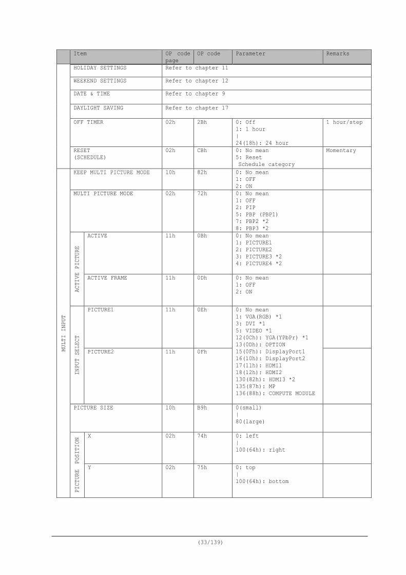
HOLIDAY SETTINGS Refer to chapter 11
WEEKEND SETTINGS Refer to chapter 12
DATE & TIME Refer to chapter 9
DAYLIGHT SAVING Refer to chapter 17
OFF TIMER 02h 2Bh 0: Off 1: 1 hour | 24(18h): 24 hour
1 hour/step
RESET (SCHEDULE)
02h CBh 0: No mean 5: Reset Schedule category
Momentary
MULT
I IN
PUT
KEEP MULTI PICTURE MODE 10h 82h 0: No mean 1: OFF 2: ON
MULTI PICTURE MODE 02h 72h 0: No mean 1: OFF 2: PIP 5: PBP (PBP1) 7: PBP2 *2 8: PBP3 *2
ACTI
VE P
ICTU
RE
ACTIVE 11h 0Bh 0: No mean 1: PICTURE1 2: PICTURE2 3: PICTURE3 *2 4: PICTURE4 *2
ACTIVE FRAME 11h 0Dh 0: No mean 1: OFF 2: ON
INPU
T SE
LECT
PICTURE1 11h 0Eh 0: No mean 1: VGA(RGB) *1 3: DVI *1 5: VIDEO *1 12(0Ch): YGA(YPbPr) *1 13(0Dh): OPTION 15(0Fh): DisplayPort1 16(10h): DisplayPort2 17(11h): HDMI1 18(12h): HDMI2 130(82h): HDMI3 *2 135(87h): MP 136(88h): COMPUTE MODULE
PICTURE2 11h 0Fh
PICTURE SIZE 10h B9h 0(small) | 80(large)
PICT
URE POS
ITIO
N
X 02h 74h 0: left | 100(64h): right
Y 02h 75h 0: top | 100(64h): bottom

(34/139)
Item OP code page
OP code Parameter Remarks
ASPECT 10h 83h 0: No mean 1: NORMAL 2: FULL 6: EXPAND
RO
TATE
*2
ROTATE ALL 11h 16h 0: No mean 1: OFF 2: ON
PICTURE1 11h 12h PICTURE2 11h 13h PICTURE3 11h 14h PICTURE4 11h 15h
TEXT
TIC
KER
MODE 10h 08h 0: No mean 1: OFF 2: HORIZONTAL 3: VERTICAL
POSITION 10h 09h 0: Top/Left | 100(64h): Bottom/Right
SIZE 10h 0Ah 0-1: Do not set. 2: Narrow(2/24) | 8: Wide(8/24)
DETECT 10h 0Ch 0: No mean 1: AUTO 2: OFF
PICTURE1 11h 2Ah 0: No mean 1: VGA(RGB) *1 3: DVI *1 5: VIDEO *1 12(0Ch): YGA(YPbPr) *1 13(0Dh): OPTION 15(0Fh): DisplayPort1 16(10h): DisplayPort2 17(11h): HDMI1 18(12h): HDMI2 130(82h): HDMI3 *2 135(87h): MP 136(88h): COMPUTE MODULE
PICTURE2 11h 2Bh
INPUT DETECT 02h 40h 0: FIRST DETECT 1: LAST DETECT 2: NONE 3: VIDEO DETECT 4: CUSTOM DETECT
CUST
OM D
ETEC
T
PRIORITY1 10h 2Eh 0: No mean 1: VGA(RGB) *1 3: DVI *1 5: VIDEO *1 12(0Ch): YGA(YPbPr) *1 13(0Dh): OPTION 15(0Fh): DisplayPort1 16(10h): DisplayPort2 17(11h): HDMI1 18(12h): HDMI2 130(82h): HDMI3 *2 135(87h): MP 136(88h): COMPUTE MODULE
PRIORITY2 10h 2Fh
PRIORITY3 10h 30h
INPUT CHANGE 10h 86h 0: No mean 1: NORMAL 2: QUICK 3: SUPER
When you set up "SUPER", please set up INPUT1 and INPUT2 first.
(35/139)
Item OP code page
OP code Parameter Remarks
SUPE
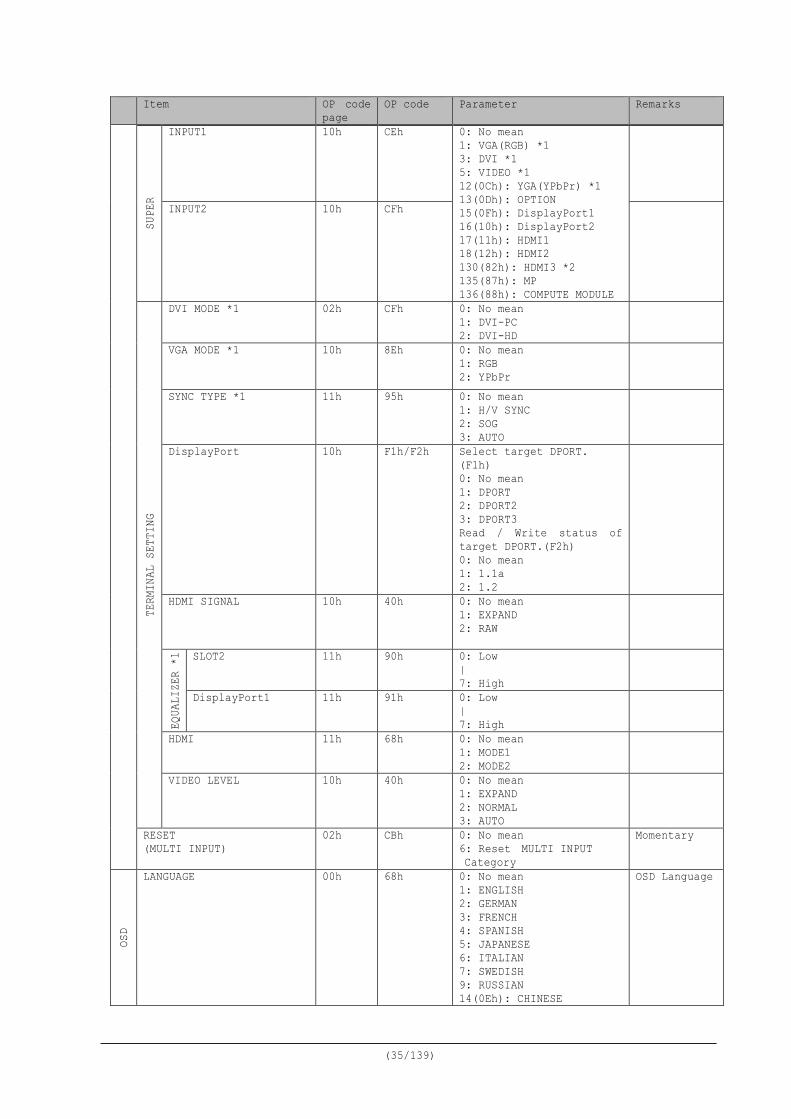
R INPUT1 10h CEh 0: No mean
1: VGA(RGB) *1 3: DVI *1 5: VIDEO *1 12(0Ch): YGA(YPbPr) *1 13(0Dh): OPTION 15(0Fh): DisplayPort1 16(10h): DisplayPort2 17(11h): HDMI1 18(12h): HDMI2 130(82h): HDMI3 *2 135(87h): MP 136(88h): COMPUTE MODULE
INPUT2 10h CFh
TERM
INAL
SET
TING
DVI MODE *1 02h CFh 0: No mean 1: DVI-PC 2: DVI-HD
VGA MODE *1 10h 8Eh 0: No mean 1: RGB 2: YPbPr
SYNC TYPE *1 11h 95h 0: No mean 1: H/V SYNC 2: SOG 3: AUTO
DisplayPort 10h F1h/F2h Select target DPORT. (F1h) 0: No mean 1: DPORT 2: DPORT2 3: DPORT3 Read / Write status of target DPORT.(F2h) 0: No mean 1: 1.1a 2: 1.2
HDMI SIGNAL 10h 40h 0: No mean 1: EXPAND 2: RAW
EQUA
LIZE
R *1
SLOT2 11h 90h 0: Low | 7: High
DisplayPort1 11h 91h 0: Low | 7: High
HDMI 11h 68h 0: No mean 1: MODE1 2: MODE2
VIDEO LEVEL 10h 40h 0: No mean 1: EXPAND 2: NORMAL 3: AUTO
RESET (MULTI INPUT)
02h CBh 0: No mean 6: Reset MULTI INPUT Category
Momentary
OSD
LANGUAGE 00h 68h 0: No mean 1: ENGLISH 2: GERMAN 3: FRENCH 4: SPANISH 5: JAPANESE 6: ITALIAN 7: SWEDISH 9: RUSSIAN 14(0Eh): CHINESE
OSD Language
(36/139)
Item OP code page
OP code Parameter Remarks
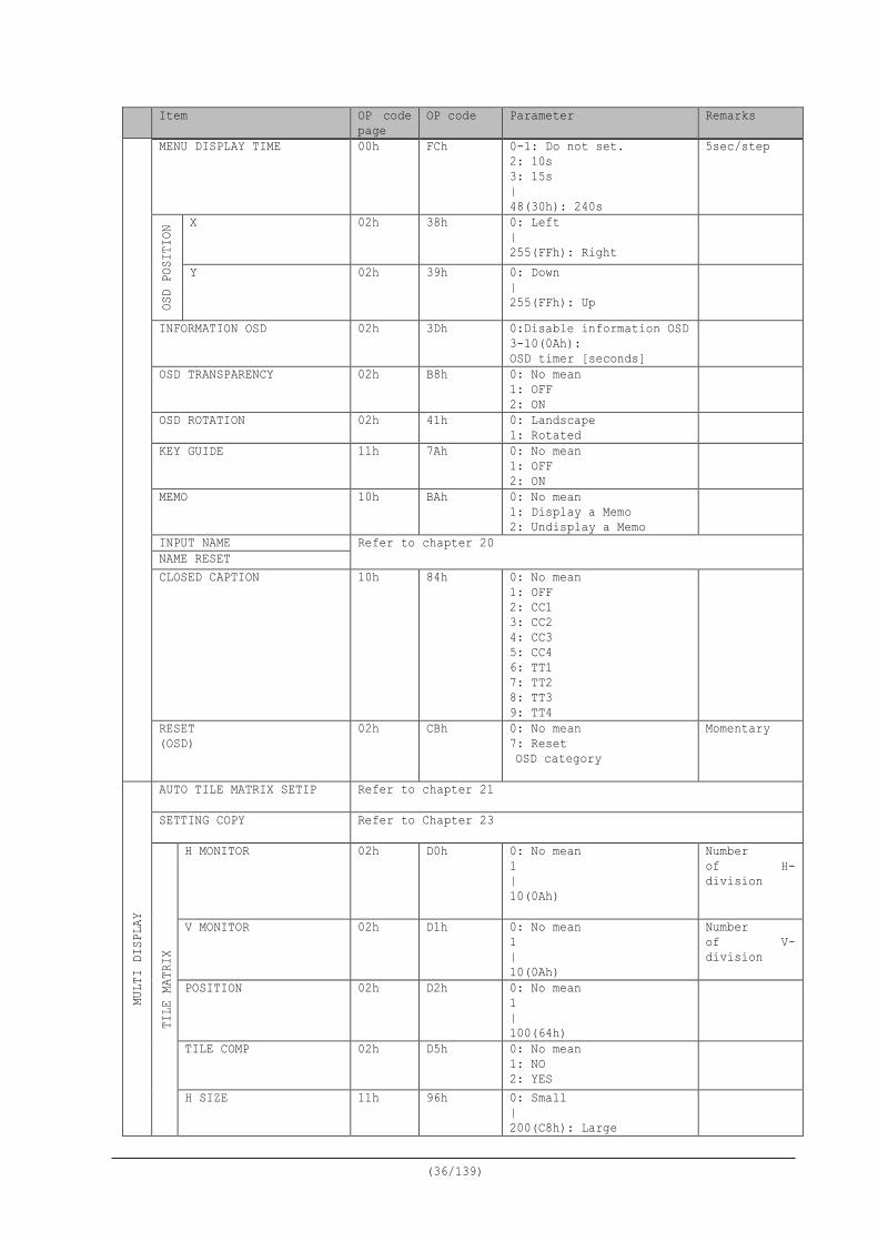
MENU DISPLAY TIME 00h FCh 0-1: Do not set. 2: 10s 3: 15s | 48(30h): 240s
5sec/step OS
D PO
SITI
ON X 02h 38h 0: Left
| 255(FFh): Right
Y 02h 39h 0: Down | 255(FFh): Up
INFORMATION OSD 02h 3Dh 0:Disable information OSD 3-10(0Ah): OSD timer [seconds]
OSD TRANSPARENCY 02h B8h 0: No mean 1: OFF 2: ON
OSD ROTATION 02h 41h 0: Landscape 1: Rotated
KEY GUIDE 11h 7Ah 0: No mean 1: OFF 2: ON
MEMO 10h BAh 0: No mean 1: Display a Memo 2: Undisplay a Memo
INPUT NAME Refer to chapter 20 NAME RESET CLOSED CAPTION 10h 84h 0: No mean
1: OFF 2: CC1 3: CC2 4: CC3 5: CC4 6: TT1 7: TT2 8: TT3 9: TT4
RESET (OSD)
02h CBh 0: No mean 7: Reset OSD category
Momentary
MULT
I DI
SPLA
Y
AUTO TILE MATRIX SETIP Refer to chapter 21
SETTING COPY Refer to Chapter 23
TILE
MAT
RIX
H MONITOR 02h D0h 0: No mean 1 | 10(0Ah)
Number of H-division
V MONITOR 02h D1h 0: No mean 1 | 10(0Ah)
Number of V-division
POSITION 02h D2h 0: No mean 1 | 100(64h)
TILE COMP 02h D5h 0: No mean 1: NO 2: YES
H SIZE 11h 96h 0: Small | 200(C8h): Large
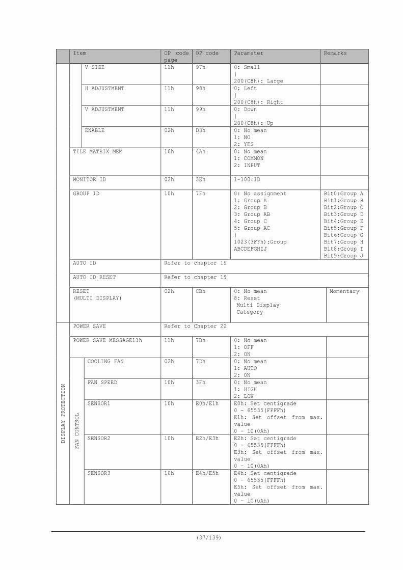
(37/139)
Item OP code page
OP code Parameter Remarks
V SIZE 11h 97h 0: Small | 200(C8h): Large
H ADJUSTMENT 11h 98h 0: Left | 200(C8h): Right
V ADJUSTMENT 11h 99h 0: Down | 200(C8h): Up
ENABLE 02h D3h 0: No mean 1: NO 2: YES
TILE MATRIX MEM 10h 4Ah 0: No mean 1: COMMON 2: INPUT
MONITOR ID 02h 3Eh 1-100:ID
GROUP ID 10h 7Fh 0: No assignment 1: Group A 2: Group B 3: Group AB 4: Group C 5: Group AC | 1023(3FFh):Group ABCDEFGHIJ
Bit0:Group A Bit1:Group B Bit2:Group C Bit3:Group D Bit4:Group E Bit5:Group F Bit6:Group G Bit7:Group H Bit8:Group I Bit9:Group J
AUTO ID Refer to chapter 19
AUTO ID RESET Refer to chapter 19
RESET (MULTI DISPLAY)
02h CBh 0: No mean 8: Reset Multi Display Category
Momentary
DISP
LAY
PROT
ECTI
ON
POWER SAVE Refer to Chapter 22
POWER SAVE MESSAGE11h 11h 7Bh 0: No mean 1: OFF 2: ON
FAN
CONT
ROL
COOLING FAN 02h 7Dh 0: No mean 1: AUTO 2: ON
FAN SPEED 10h 3Fh 0: No mean 1: HIGH 2: LOW
SENSOR1 10h E0h/E1h E0h: Set centigrade 0 – 65535(FFFFh) E1h: Set offset from max. value 0 – 10(0Ah)
SENSOR2 10h E2h/E3h E2h: Set centigrade 0 – 65535(FFFFh) E3h: Set offset from max. value 0 – 10(0Ah)
SENSOR3 10h E4h/E5h E4h: Set centigrade 0 – 65535(FFFFh) E5h: Set offset from max. value 0 – 10(0Ah)
(38/139)
Item OP code page
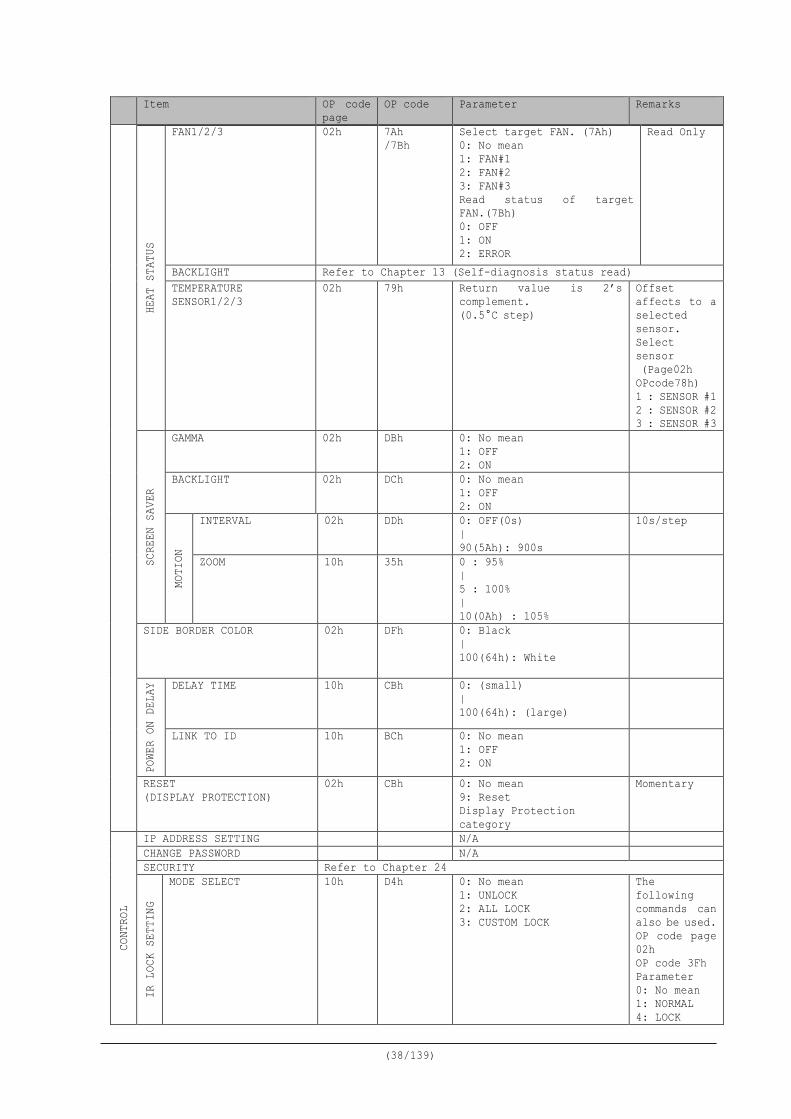
OP code Parameter Remarks
HEAT
STA
TUS
FAN1/2/3 02h 7Ah /7Bh
Select target FAN. (7Ah) 0: No mean 1: FAN#1 2: FAN#2 3: FAN#3 Read status of target FAN.(7Bh) 0: OFF 1: ON 2: ERROR
Read Only
BACKLIGHT Refer to Chapter 13 (Self-diagnosis status read) TEMPERATURE SENSOR1/2/3
02h 79h Return value is 2’s complement. (0.5°C step)
Offset affects to a selected sensor. Select sensor (Page02h OPcode78h) 1 : SENSOR #1 2 : SENSOR #2 3 : SENSOR #3
SCRE
EN S
AVER
GAMMA 02h DBh 0: No mean 1: OFF 2: ON
BACKLIGHT 02h DCh 0: No mean 1: OFF 2: ON
MOTI
ON
INTERVAL 02h DDh 0: OFF(0s) | 90(5Ah): 900s
10s/step
ZOOM 10h 35h 0 : 95% | 5 : 100% | 10(0Ah) : 105%
SIDE BORDER COLOR 02h DFh 0: Black | 100(64h): White
POWE
R ON
DEL
AY DELAY TIME 10h CBh 0: (small)
| 100(64h): (large)
LINK TO ID 10h BCh 0: No mean 1: OFF 2: ON
RESET (DISPLAY PROTECTION)
02h CBh 0: No mean 9: Reset Display Protection category
Momentary
CONT
ROL
IP ADDRESS SETTING N/A CHANGE PASSWORD N/A SECURITY Refer to Chapter 24
IR L
OCK
SETT
ING
MODE SELECT 10h D4h 0: No mean 1: UNLOCK 2: ALL LOCK 3: CUSTOM LOCK
The following commands can also be used. OP code page 02h OP code 3Fh Parameter 0: No mean 1: NORMAL 4: LOCK
(39/139)
Item OP code page
OP code Parameter Remarks
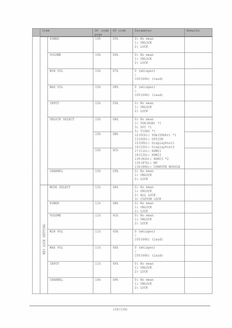
POWER 10h D5h 0: No mean 1: UNLOCK 2: LOCK
VOLUME 10h D6h 0: No mean 1: UNLOCK 2: LOCK
MIN VOL 10h D7h 0 (whisper) | 100(64h) (laud)
MAX VOL 10h D8h 0 (whisper) | 100(64h) (laud)
INPUT 10h D9h 0: No mean 1: UNLOCK 2: LOCK
UNLOCK SELECT 10h DAh 0: No mean 1: VGA(RGB) *1 3: DVI *1 5: VIDEO *1 12(0Ch): YGA(YPbPr) *1 13(0Dh): OPTION 15(0Fh): DisplayPort1 16(10h): DisplayPort2 17(11h): HDMI1 18(12h): HDMI2 130(82h): HDMI3 *2 135(87h): MP 136(88h): COMPUTE MODULE
10h DBh
10h DCh
CHANNEL 10h D9h 0: No mean 1: UNLOCK 2: LOCK
KEY
LOCK
SET
TING
MODE SELECT 11h 6Ah 0: No mean 1: UNLOCK 2: ALL LOCK 3: CUSTOM LOCK
POWER 11h 6Bh 0: No mean 1: UNLOCK 2: LOCK
VOLUME 11h 6Ch 0: No mean 1: UNLOCK 2: LOCK
MIN VOL 11h 6Dh 0 (whisper) | 100(64h) (laud)
MAX VOL 11h 6Eh 0 (whisper) | 100(64h) (laud)
INPUT 11h 6Fh 0: No mean 1: UNLOCK 2: LOCK
CHANNEL 10h D9h 0: No mean 1: UNLOCK 2: LOCK
(40/139)
Item OP code page
OP code Parameter Remarks
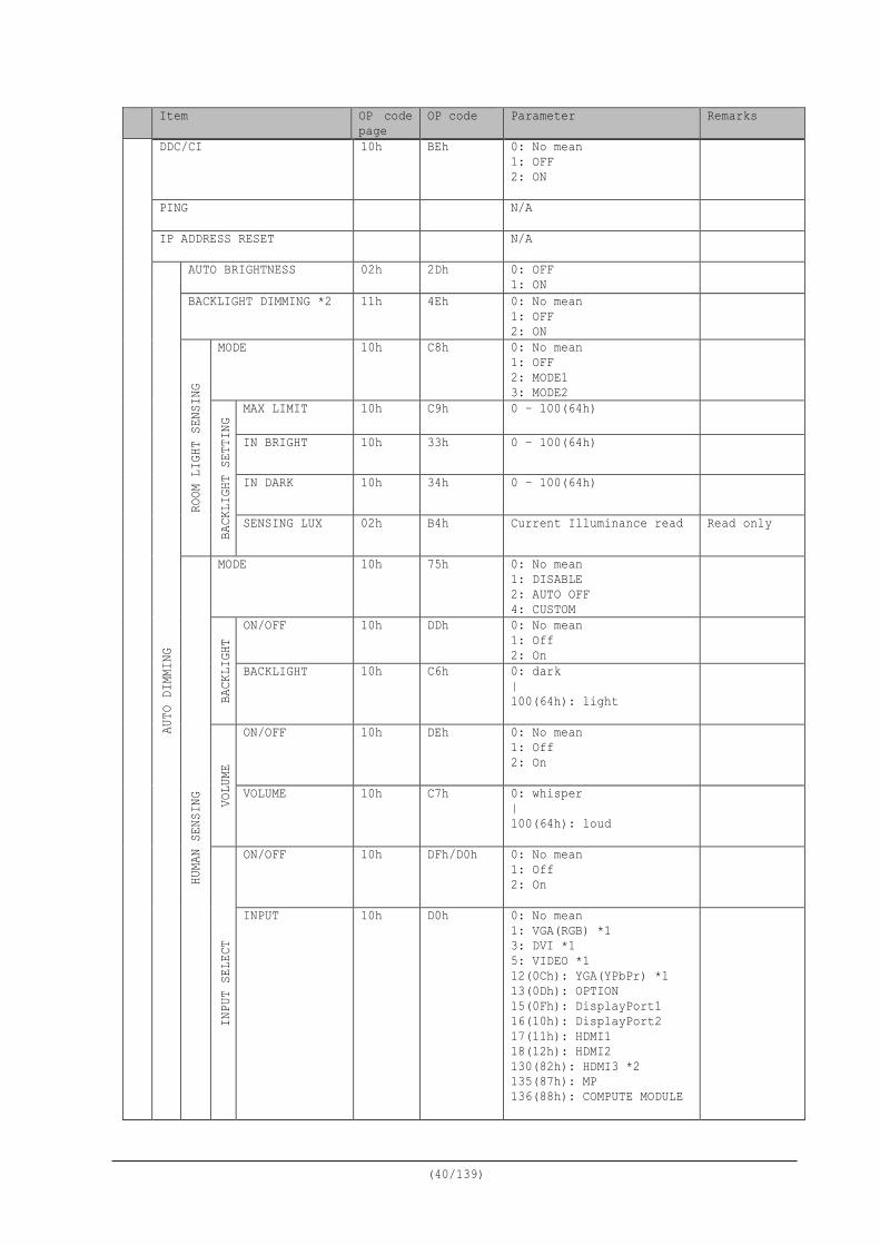
DDC/CI 10h BEh 0: No mean 1: OFF 2: ON
PING N/A
IP ADDRESS RESET N/A
AUTO
DIM
MING
AUTO BRIGHTNESS 02h 2Dh 0: OFF 1: ON
BACKLIGHT DIMMING *2
11h 4Eh 0: No mean 1: OFF 2: ON
ROOM
LIG
HT S
ENSI
NG
MODE 10h C8h 0: No mean 1: OFF 2: MODE1 3: MODE2
BACK
LIGH
T SE
TTIN
G
MAX LIMIT 10h C9h 0 – 100(64h)
IN BRIGHT 10h 33h
0 – 100(64h)
IN DARK 10h 34h 0 – 100(64h)
SENSING LUX 02h B4h Current Illuminance read Read only
HUMA
N SE
NSIN
G
MODE 10h 75h 0: No mean 1: DISABLE 2: AUTO OFF 4: CUSTOM
BACK
LIGH
T
ON/OFF 10h DDh 0: No mean 1: Off 2: On
BACKLIGHT 10h C6h 0: dark | 100(64h): light
VOLU
ME
ON/OFF 10h DEh 0: No mean 1: Off 2: On
VOLUME 10h C7h 0: whisper | 100(64h): loud
INPU
T SE
LECT
ON/OFF 10h DFh/D0h 0: No mean 1: Off 2: On
INPUT 10h D0h 0: No mean 1: VGA(RGB) *1 3: DVI *1 5: VIDEO *1 12(0Ch): YGA(YPbPr) *1 13(0Dh): OPTION 15(0Fh): DisplayPort1 16(10h): DisplayPort2 17(11h): HDMI1 18(12h): HDMI2 130(82h): HDMI3 *2 135(87h): MP 136(88h): COMPUTE MODULE
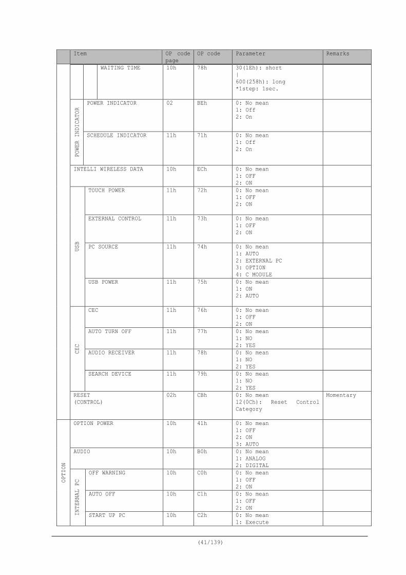
(41/139)
Item OP code page
OP code Parameter Remarks
WAITING TIME 10h 78h 30(1Eh): short | 600(258h): long *1step: 1sec.
PO
WER
INDI
CATO
R
POWER INDICATOR 02 BEh 0: No mean 1: Off 2: On
SCHEDULE INDICATOR 11h 71h 0: No mean 1: Off 2: On
INTELLI WIRELESS DATA 10h ECh 0: No mean 1: OFF 2: ON
USB
TOUCH POWER 11h 72h 0: No mean 1: OFF 2: ON
EXTERNAL CONTROL 11h 73h 0: No mean 1: OFF 2: ON
PC SOURCE 11h 74h 0: No mean 1: AUTO 2: EXTERNAL PC 3: OPTION 4: C MODULE
USB POWER 11h 75h 0: No mean 1: ON 2: AUTO
CEC
CEC 11h 76h 0: No mean 1: OFF 2: ON
AUTO TURN OFF 11h 77h 0: No mean 1: NO 2: YES
AUDIO RECEIVER 11h 78h 0: No mean 1: NO 2: YES
SEARCH DEVICE 11h 79h 0: No mean 1: NO 2: YES
RESET (CONTROL)
02h CBh 0: No mean 12(0Ch): Reset Control Category
Momentary
OPTI
ON
OPTION POWER 10h
41h
0: No mean 1: OFF 2: ON 3: AUTO
AUDIO 10h B0h 0: No mean 1: ANALOG 2: DIGITAL
INTE
RNAL
PC
OFF WARNING 10h C0h 0: No mean 1: OFF 2: ON
AUTO OFF 10h C1h 0: No mean 1: OFF 2: ON
START UP PC 10h C2h 0: No mean 1: Execute
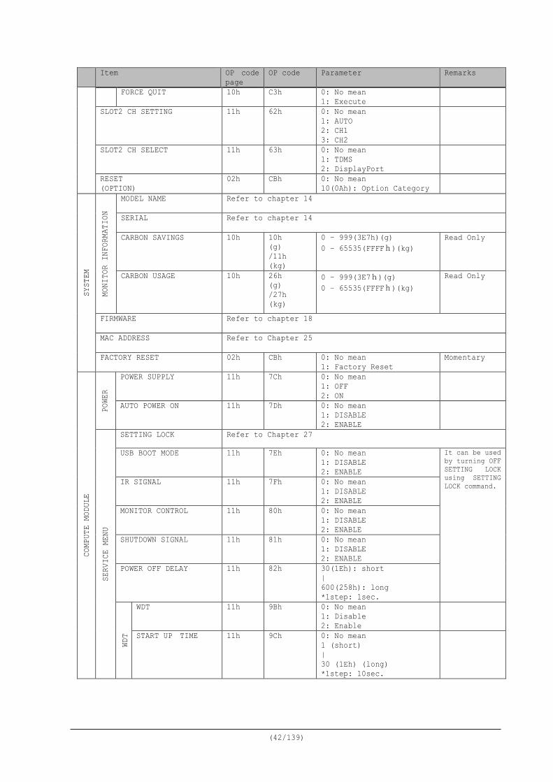
(42/139)
Item OP code page
OP code Parameter Remarks
FORCE QUIT 10h C3h 0: No mean 1: Execute
SLOT2 CH SETTING 11h 62h 0: No mean 1: AUTO 2: CH1 3: CH2
SLOT2 CH SELECT 11h 63h 0: No mean 1: TDMS 2: DisplayPort
RESET (OPTION)
02h CBh 0: No mean 10(0Ah): Option Category
SYST
EM
MONI
TOR
INFO
RMAT
ION
MODEL NAME Refer to chapter 14
SERIAL Refer to chapter 14
CARBON SAVINGS 10h 10h (g) /11h (kg)
0 – 999(3E7h)(g) 0 – 65535(FFFFh)(kg)
Read Only
CARBON USAGE 10h 26h (g) /27h (kg)
0 – 999(3E7h)(g) 0 – 65535(FFFFh)(kg)
Read Only
FIRMWARE Refer to chapter 18
MAC ADDRESS Refer to Chapter 25
FACTORY RESET 02h CBh 0: No mean 1: Factory Reset
Momentary
COMP
UTE
MODU
LE
POWE
R
POWER SUPPLY 11h 7Ch 0: No mean 1: OFF 2: ON
AUTO POWER ON 11h 7Dh 0: No mean 1: DISABLE 2: ENABLE
SERV
ICE
MENU
SETTING LOCK Refer to Chapter 27
USB BOOT MODE 11h 7Eh 0: No mean 1: DISABLE 2: ENABLE
It can be used by turning OFF SETTING LOCK using SETTING LOCK command. IR SIGNAL 11h 7Fh 0: No mean
1: DISABLE 2: ENABLE
MONITOR CONTROL 11h 80h 0: No mean 1: DISABLE 2: ENABLE
SHUTDOWN SIGNAL 11h 81h 0: No mean 1: DISABLE 2: ENABLE
POWER OFF DELAY 11h 82h 30(1Eh): short | 600(258h): long *1step: 1sec.
WDT
WDT 11h 9Bh 0: No mean 1: Disable 2: Enable
START UP TIME 11h 9Ch 0: No mean 1 (short) | 30 (1Eh) (long) *1step: 10sec.
(43/139)
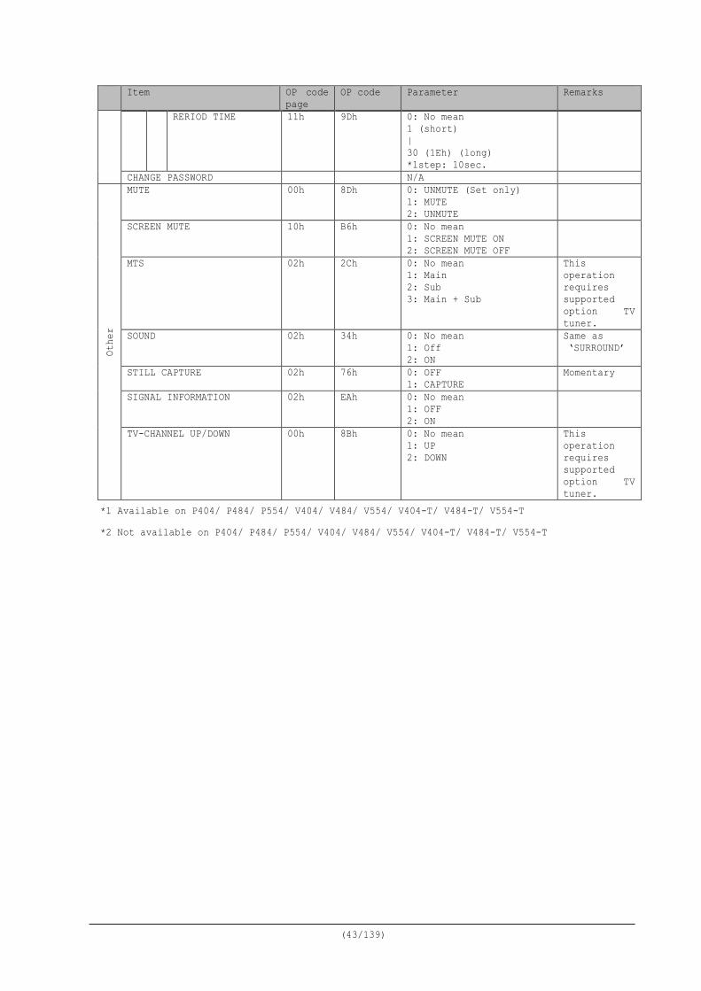
Item OP code page
OP code Parameter Remarks
RERIOD TIME 11h
9Dh
0: No mean 1 (short) | 30 (1Eh) (long) *1step: 10sec.
CHANGE PASSWORD N/A
Othe
r
MUTE 00h 8Dh 0: UNMUTE (Set only) 1: MUTE 2: UNMUTE
SCREEN MUTE 10h B6h 0: No mean 1: SCREEN MUTE ON 2: SCREEN MUTE OFF
MTS 02h 2Ch 0: No mean 1: Main 2: Sub 3: Main + Sub
This operation requires supported option TV tuner.
SOUND 02h 34h 0: No mean 1: Off 2: ON
Same as ‘SURROUND’
STILL CAPTURE 02h 76h 0: OFF 1: CAPTURE
Momentary
SIGNAL INFORMATION 02h EAh 0: No mean 1: OFF 2: ON
TV-CHANNEL UP/DOWN 00h 8Bh 0: No mean 1: UP 2: DOWN
This operation requires supported option TV tuner.
*1 Available on P404/ P484/ P554/ V404/ V484/ V554/ V404-T/ V484-T/ V554-T *2 Not available on P404/ P484/ P554/ V404/ V484/ V554/ V404-T/ V484-T/ V554-T
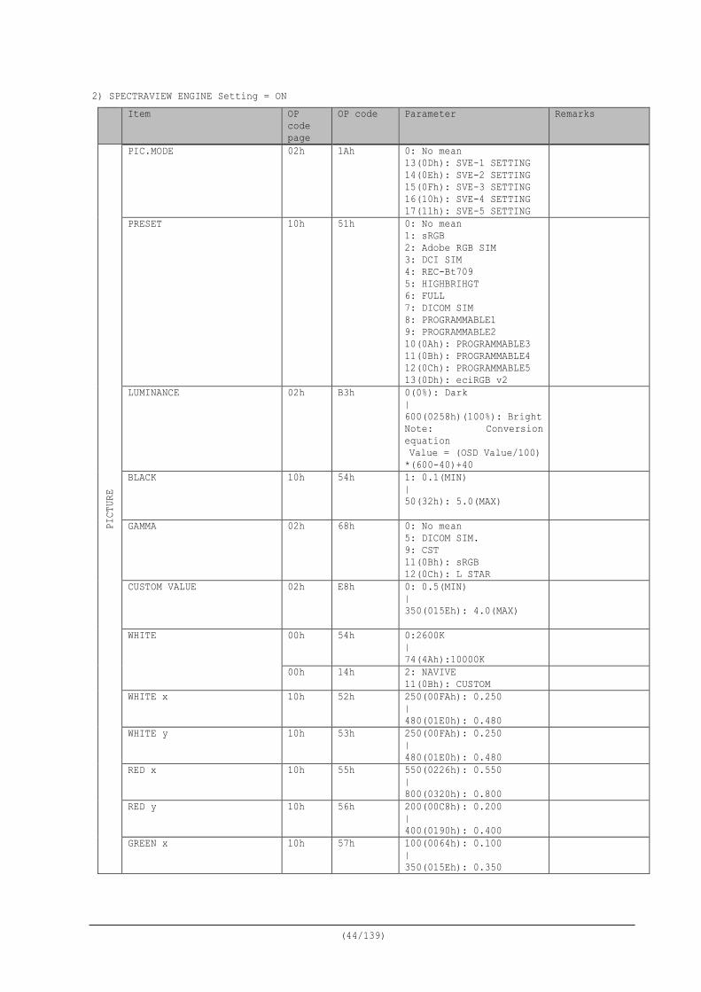
(44/139)
2) SPECTRAVIEW ENGINE Setting = ON Item OP
code page
OP code Parameter Remarks PI
CTUR
E
PIC.MODE 02h 1Ah 0: No mean 13(0Dh): SVE-1 SETTING 14(0Eh): SVE-2 SETTING 15(0Fh): SVE-3 SETTING 16(10h): SVE-4 SETTING 17(11h): SVE-5 SETTING
PRESET 10h 51h 0: No mean 1: sRGB 2: Adobe RGB SIM 3: DCI SIM 4: REC-Bt709 5: HIGHBRIHGT 6: FULL 7: DICOM SIM 8: PROGRAMMABLE1 9: PROGRAMMABLE2 10(0Ah): PROGRAMMABLE3 11(0Bh): PROGRAMMABLE4 12(0Ch): PROGRAMMABLE5 13(0Dh): eciRGB v2
LUMINANCE 02h B3h 0(0%): Dark | 600(0258h)(100%): Bright Note: Conversion equation Value = (OSD Value/100) *(600-40)+40
BLACK
10h 54h 1: 0.1(MIN) | 50(32h): 5.0(MAX)
GAMMA 02h 68h 0: No mean 5: DICOM SIM. 9: CST 11(0Bh): sRGB 12(0Ch): L STAR
CUSTOM VALUE 02h E8h 0: 0.5(MIN) | 350(015Eh): 4.0(MAX)
WHITE 00h 54h 0:2600K | 74(4Ah):10000K
00h 14h 2: NAVIVE 11(0Bh): CUSTOM
WHITE x 10h 52h 250(00FAh): 0.250 | 480(01E0h): 0.480
WHITE y 10h 53h 250(00FAh): 0.250 | 480(01E0h): 0.480
RED x
10h 55h 550(0226h): 0.550 | 800(0320h): 0.800
RED y 10h 56h 200(00C8h): 0.200 | 400(0190h): 0.400
GREEN x 10h 57h 100(0064h): 0.100 | 350(015Eh): 0.350
(45/139)
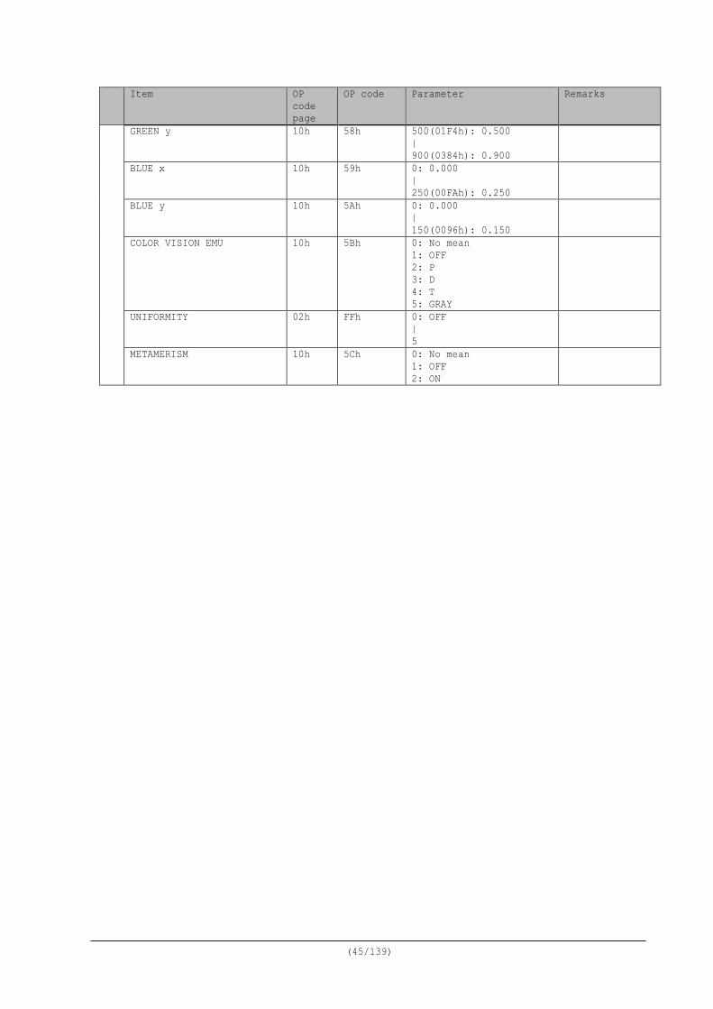
Item OP code page
OP code Parameter Remarks
GREEN y 10h 58h 500(01F4h): 0.500 | 900(0384h): 0.900
BLUE x 10h 59h 0: 0.000 | 250(00FAh): 0.250
BLUE y 10h 5Ah 0: 0.000 | 150(0096h): 0.150
COLOR VISION EMU 10h 5Bh 0: No mean 1: OFF 2: P 3: D 4: T 5: GRAY
UNIFORMITY 02h FFh 0: OFF | 5
METAMERISM 10h 5Ch 0: No mean 1: OFF 2: ON
(46/139)
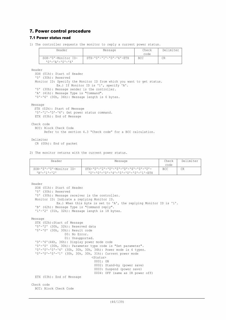
7. Power control procedure 7.1 Power status read 1) The controller requests the monitor to reply a current power status.
Header Message Check code
Delimiter
SOH-'0'-Monitor ID- '0'-'A'-'0'-'6'
STX-'0'-'1'-'D'-'6'-ETX BCC CR
Header
SOH (01h): Start of Header '0' (30h): Reserved Monitor ID: Specify the Monitor ID from which you want to get status.
Ex.) If Monitor ID is '1', specify 'A'. '0' (30h): Message sender is the controller. 'A' (41h): Message Type is "Command". '0'-'6' (30h, 36h): Message length is 6 bytes.
Message STX (02h): Start of Message '0'-'1'-'D'-'6': Get power status command. ETX (03h): End of Message
Check code
BCC: Block Check Code Refer to the section 4.3 “Check code” for a BCC calculation.
Delimiter CR (0Dh): End of packet
2) The monitor returns with the current power status.
Header
SOH (01h): Start of Header '0' (30h): Reserved '0' (30h): Message receiver is the controller. Monitor ID: Indicate a replying Monitor ID.
Ex.) When this byte is set to 'A', the replying Monitor ID is '1'. 'B' (42h): Message Type is "Command reply". '1'-'2' (31h, 32h): Message length is 18 bytes.
Message STX (02h):Start of Message '0'-'2' (30h, 32h): Reserved data '0'-'0' (30h, 30h): Result code
00: No Error. 01: Unsupported.
'D'-'6'(44h, 36h): Display power mode code '0'-'0' (30h, 30h): Parameter type code is "Set parameter". '0'-'0'-'0'-'4' (30h, 30h, 30h, 34h): Power mode is 4 types. '0'-'0'-'0'-'1' (30h, 30h, 30h, 31h): Current power mode
<Status> 0001: ON 0002: Stand-by (power save) 0003: Suspend (power save) 0004: OFF (same as IR power off)
ETX (03h): End of Message
Check code BCC: Block Check Code
Header Message Check code
Delimiter
SOH-'0'-'0'-Monitor ID- 'B'-'1'-'2'
STX-'0'-'2'-'0'-'0'-'D'-'6'-'0'-'0'- '0'-'0'-'0'-'4'-'0'-'0'-'0'-'1'-ETX
BCC CR

(47/139)
Refer to the section 4.3 “Check code” for a BCC calculation. Delimiter
CR (0Dh): End of packet
(48/139)
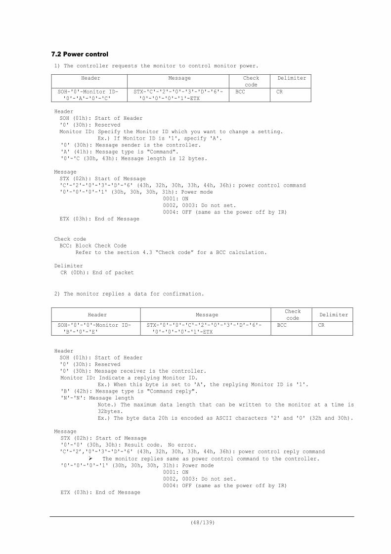
7.2 Power control 1) The controller requests the monitor to control monitor power.
Header SOH (01h): Start of Header '0' (30h): Reserved Monitor ID: Specify the Monitor ID which you want to change a setting.
Ex.) If Monitor ID is '1', specify 'A'. '0' (30h): Message sender is the controller. 'A' (41h): Message type is "Command". '0'-'C (30h, 43h): Message length is 12 bytes.
Message STX (02h): Start of Message 'C'-'2'-'0'-'3'-'D'-'6' (43h, 32h, 30h, 33h, 44h, 36h): power control command '0'-'0'-'0'-'1' (30h, 30h, 30h, 31h): Power mode
0001: ON 0002, 0003: Do not set. 0004: OFF (same as the power off by IR)
ETX (03h): End of Message
Check code BCC: Block Check Code Refer to the section 4.3 “Check code” for a BCC calculation.
Delimiter
CR (0Dh): End of packet 2) The monitor replies a data for confirmation.
Header SOH (01h): Start of Header
'0' (30h): Reserved '0' (30h): Message receiver is the controller. Monitor ID: Indicate a replying Monitor ID.
Ex.) When this byte is set to 'A', the replying Monitor ID is '1'. 'B' (42h): Message type is "Command reply". 'N'-'N': Message length
Note.) The maximum data length that can be written to the monitor at a time is 32bytes. Ex.) The byte data 20h is encoded as ASCII characters '2' and '0' (32h and 30h).
Message STX (02h): Start of Message '0'-'0' (30h, 30h): Result code. No error. 'C'-'2’,'0'-'3'-'D'-'6' (43h, 32h, 30h, 33h, 44h, 36h): power control reply command
The monitor replies same as power control command to the controller. '0'-'0'-'0'-'1' (30h, 30h, 30h, 31h): Power mode
0001: ON 0002, 0003: Do not set. 0004: OFF (same as the power off by IR)
ETX (03h): End of Message
Header Message Check code
Delimiter
SOH-'0'-Monitor ID- '0'-'A'-'0'-'C'
STX-'C'-'2'-'0'-'3'-'D'-'6'- '0'-'0'-'0'-'1'-ETX
BCC CR
Header Message Check code Delimiter
SOH-'0'-'0'-Monitor ID- 'B'-'0'-'E'
STX-'0'-'0'-'C'-'2'-'0'-'3'-'D'-'6'- '0'-'0'-'0'-'1'-ETX
BCC CR

(49/139)
Check code BCC: Block Check Code Refer to the section 4.3 “Check code” for a BCC calculation.
Delimiter
CR (0Dh): End of packet
(50/139)
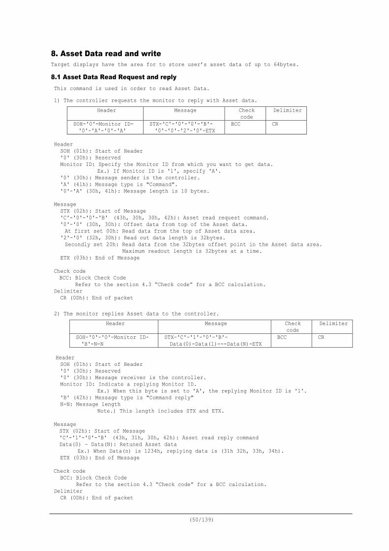
8. Asset Data read and write Target displays have the area for to store user’s asset data of up to 64bytes.
8.1 Asset Data Read Request and reply This command is used in order to read Asset Data. 1) The controller requests the monitor to reply with Asset data.
Header Message Check code
Delimiter
SOH-'0'-Monitor ID- '0'-'A'-'0'-'A'
STX-'C'-'0'-'0'-'B'- '0'-'0'-'2'-'0'-ETX
BCC CR
Header
SOH (01h): Start of Header '0' (30h): Reserved Monitor ID: Specify the Monitor ID from which you want to get data.
Ex.) If Monitor ID is '1', specify 'A'. '0' (30h): Message sender is the controller. 'A' (41h): Message type is "Command". '0'-'A' (30h, 41h): Message length is 10 bytes.
Message STX (02h): Start of Message 'C'-'0'-'0'-'B' (43h, 30h, 30h, 42h): Asset read request command. '0'-'0' (30h, 30h): Offset data from top of the Asset data. At first set 00h: Read data from the top of Asset data area.
'2'-'0' (32h, 30h): Read out data length is 32bytes. Secondly set 20h: Read data from the 32bytes offset point in the Asset data area.
Maximum readout length is 32bytes at a time. ETX (03h): End of Message
Check code BCC: Block Check Code Refer to the section 4.3 “Check code” for a BCC calculation.
Delimiter CR (0Dh): End of packet
2) The monitor replies Asset data to the controller.
Header Message Check code
Delimiter
SOH-'0'-'0'-Monitor ID- 'B'-N-N
STX-'C'-'1'-'0'-'B'- Data(0)-Data(1)---Data(N)-ETX
BCC CR
Header SOH (01h): Start of Header '0' (30h): Reserved '0' (30h): Message receiver is the controller. Monitor ID: Indicate a replying Monitor ID.
Ex.) When this byte is set to 'A', the replying Monitor ID is '1'. 'B' (42h): Message type is "Command reply" N-N: Message length
Note.) This length includes STX and ETX. Message STX (02h): Start of Message 'C'-'1'-'0'-'B' (43h, 31h, 30h, 42h): Asset read reply command Data(0) – Data(N): Retuned Asset data
Ex.) When Data(n) is 1234h, replying data is (31h 32h, 33h, 34h). ETX (03h): End of Message
Check code BCC: Block Check Code Refer to the section 4.3 “Check code” for a BCC calculation.
Delimiter CR (0Dh): End of packet
(51/139)
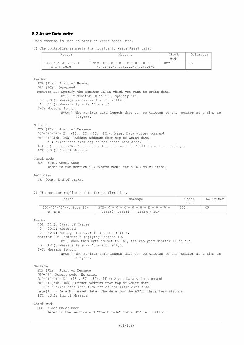
8.2 Asset Data write This command is used in order to write Asset Data. 1) The controller requests the monitor to write Asset data.
Header Message Check code
Delimiter
SOH-'0'-Monitor ID- '0'-'A'-N-N
STX-'C'-'0'-'0'-'E'-'0'-'0'- Data(0)-Data(1)---Data(N)-ETX
BCC CR
Header SOH (01h): Start of Header '0' (30h): Reserved Monitor ID: Specify the Monitor ID in which you want to write data.
Ex.) If Monitor ID is '1', specify 'A'. '0' (30h): Message sender is the controller. 'A' (41h): Message type is "Command". N-N: Message length
Note.) The maximum data length that can be written to the monitor at a time is 32bytes.
Message STX (02h): Start of Message 'C'-'0'-'0'-'E' (43h, 30h, 30h, 45h): Asset Data writes command '0'-'0'(30h, 30h): Offset address from top of Asset data.
00h : Write data from top of the Asset data area. Data(0) –- Data(N): Asset data. The data must be ASCII characters strings. ETX (03h): End of Message
Check code BCC: Block Check Code Refer to the section 4.3 “Check code” for a BCC calculation.
Delimiter
CR (0Dh): End of packet 2) The monitor replies a data for confirmation.
Header Message Check code
Delimiter
SOH-'0'-'0'-Monitor ID- 'B'-N-N
STX-'0'-'0'-'C'-'0'-'0'-'E'-'0'-'0'- Data(0)-Data(1)---Data(N)-ETX
BCC CR
Header
SOH (01h): Start of Header '0' (30h): Reserved '0' (30h): Message receiver is the controller. Monitor ID: Indicate a replying Monitor ID.
Ex.) When this byte is set to 'A', the replying Monitor ID is '1'. 'B' (42h): Message type is "Command reply". N-N: Message length
Note.) The maximum data length that can be written to the monitor at a time is 32bytes.
Message STX (02h): Start of Message '0'-'0': Result code. No error. 'C'-'0'-'0'-'E' (43h, 30h, 30h, 45h): Asset Data write command '0'-'0'(30h, 30h): Offset address from top of Asset data.
00h : Write data into from top of the Asset data area. Data(0) –- Data(N): Asset data. The data must be ASCII characters strings. ETX (03h): End of Message
Check code BCC: Block Check Code Refer to the section 4.3 “Check code” for a BCC calculation.

(52/139)
Delimiter
CR (0Dh): End of packet
(53/139)
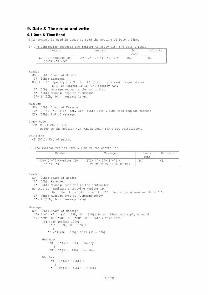
9. Date & Time read and write 9.1 Date & Time Read This command is used in order to read the setting of Date & Time. 1) The controller requests the monitor to reply with the Date & Time.
Header Message Check code
Delimiter
SOH-'0'-Monitor ID- '0'-'A'-'0'-'6'
STX-'C'-'2'-'1'-'1'-ETX BCC CR
Header
SOH (01h): Start of Header '0' (30h): Reserved Monitor ID: Specify the Monitor ID of which you want to get status.
Ex.) If Monitor ID is '1', specify 'A'. '0' (30h): Message sender is the controller. 'A' (41h): Message type is "Command". '0'-'6'(30h, 36h): Message length
Message STX (02h): Start of Message 'C'-'2'-'1'-'1' (43h, 32h, 31h, 31h): Date & time read request command. ETX (03h): End of Message
Check code BCC: Block Check Code Refer to the section 4.3 “Check code” for a BCC calculation.
Delimiter
CR (0Dh): End of packet 2) The monitor replies Date & Time to the controller.
Header Message Check code
Delimiter
SOH-'0'-'0'-Monitor ID- 'B'-'1'-'4'
STX-'C'-'3'-'1'-'1'- YY-MM-DD-WW-HH-MN-DS-ETX
BCC CR
Header
SOH (01h): Start of Header '0' (30h): Reserved '0' (30h): Message receiver is the controller Monitor ID: Indicate a replying Monitor ID
Ex.) When this byte is set to 'A', the replying Monitor ID is '1'. 'B' (42h): Message type is "Command reply" '1'-'4'(31h, 34h): Message length
Message STX (02h): Start of Message 'C'-'3'-'1'-'1' (43h, 33h, 31h, 31h): Date & Time read reply command 'YY'-'MM'-'DD'-'WW'-'HH'-'MN'-'DS': Date & Time data
YY: Year (offset 2000) '0'-'0'(30h, 30h): 2000 |
'6'-'3'(36h, 33h): 2099 (99 = 63h)
MM: Month '0'-'1'(30h, 31h): January | '0'-'C'(30h, 43h): December
DD: Day
'0'-'1'(30h, 31h): 1 | '1'-'E'(31h, 45h): 30(=1Eh)
(54/139)
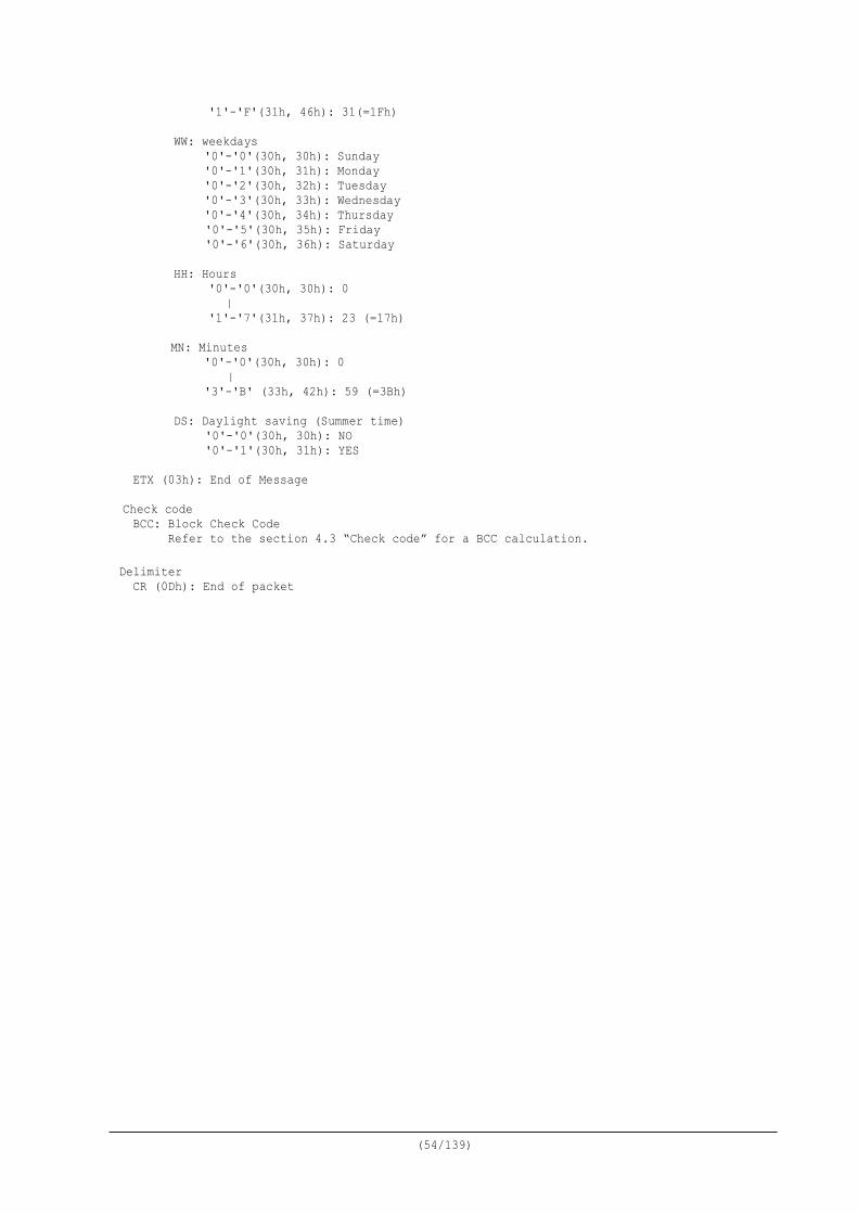
'1'-'F'(31h, 46h): 31(=1Fh) WW: weekdays
'0'-'0'(30h, 30h): Sunday '0'-'1'(30h, 31h): Monday '0'-'2'(30h, 32h): Tuesday '0'-'3'(30h, 33h): Wednesday '0'-'4'(30h, 34h): Thursday '0'-'5'(30h, 35h): Friday '0'-'6'(30h, 36h): Saturday
HH: Hours
'0'-'0'(30h, 30h): 0 | '1'-'7'(31h, 37h): 23 (=17h)
MN: Minutes '0'-'0'(30h, 30h): 0 | '3'-'B' (33h, 42h): 59 (=3Bh)
DS: Daylight saving (Summer time)
'0'-'0'(30h, 30h): NO '0'-'1'(30h, 31h): YES
ETX (03h): End of Message Check code BCC: Block Check Code Refer to the section 4.3 “Check code” for a BCC calculation.
Delimiter
CR (0Dh): End of packet
(55/139)
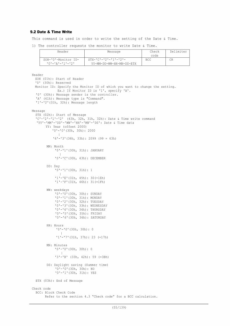
9.2 Date & Time Write This command is used in order to write the setting of the Date & Time. 1) The controller requests the monitor to write Date & Time.
Header Message Check code
Delimiter
SOH-'0'-Monitor ID- '0'-'A'-'1'-'2'
STX-'C'-'2'-'1'-'2'- YY-MM-DD-WW-HH-MN-DS-ETX
BCC CR
Header SOH (01h): Start of Header '0' (30h): Reserved Monitor ID: Specify the Monitor ID of which you want to change the setting.
Ex.) If Monitor ID is '1', specify 'A'. '0' (30h): Message sender is the controller. 'A' (41h): Message type is "Command". '1'-'2'(31h, 32h): Message length
Message STX (02h): Start of Message 'C'-'2'-'1'-'2' (43h, 32h, 31h, 32h): Date & Time write command 'YY'-'MM'-'DD'-'WW'-'HH'-'MN'-'DS': Date & Time data
YY: Year (offset 2000) '0'-'0'(30h, 30h): 2000
| '6'-'3'(36h, 33h): 2099 (99 = 63h)
MM: Month
'0'-'1'(30h, 31h): JANUARY | '0'-'C'(30h, 43h): DECEMBER
DD: Day '0'-'1'(30h, 31h): 1 | '1'-'E'(31h, 45h): 30(=1Eh) '1'-'F'(31h, 46h): 31(=1Fh)
WW: weekdays
'0'-'0'(30h, 30h): SUNDAY '0'-'1'(30h, 31h): MONDAY '0'-'2'(30h, 32h): TUESDAY '0'-'3'(30h, 33h): WEDNESDAY '0'-'4'(30h, 34h): THURSDAY '0'-'5'(30h, 35h): FRIDAY '0'-'6'(30h, 36h): SATURDAY
HH: Hours
'0'-'0'(30h, 30h): 0 | '1'-'7'(31h, 37h): 23 (=17h)
MN: Minutes
'0'-'0'(30h, 30h): 0 | '3'-'B' (33h, 42h): 59 (=3Bh)
DS: Daylight saving (Summer time)
'0'-'0'(30h, 30h): NO '0'-'1'(30h, 31h): YES
ETX (03h): End of Message Check code
BCC: Block Check Code Refer to the section 4.3 “Check code” for a BCC calculation.
(56/139)
Delimiter
CR (0Dh): End of packet
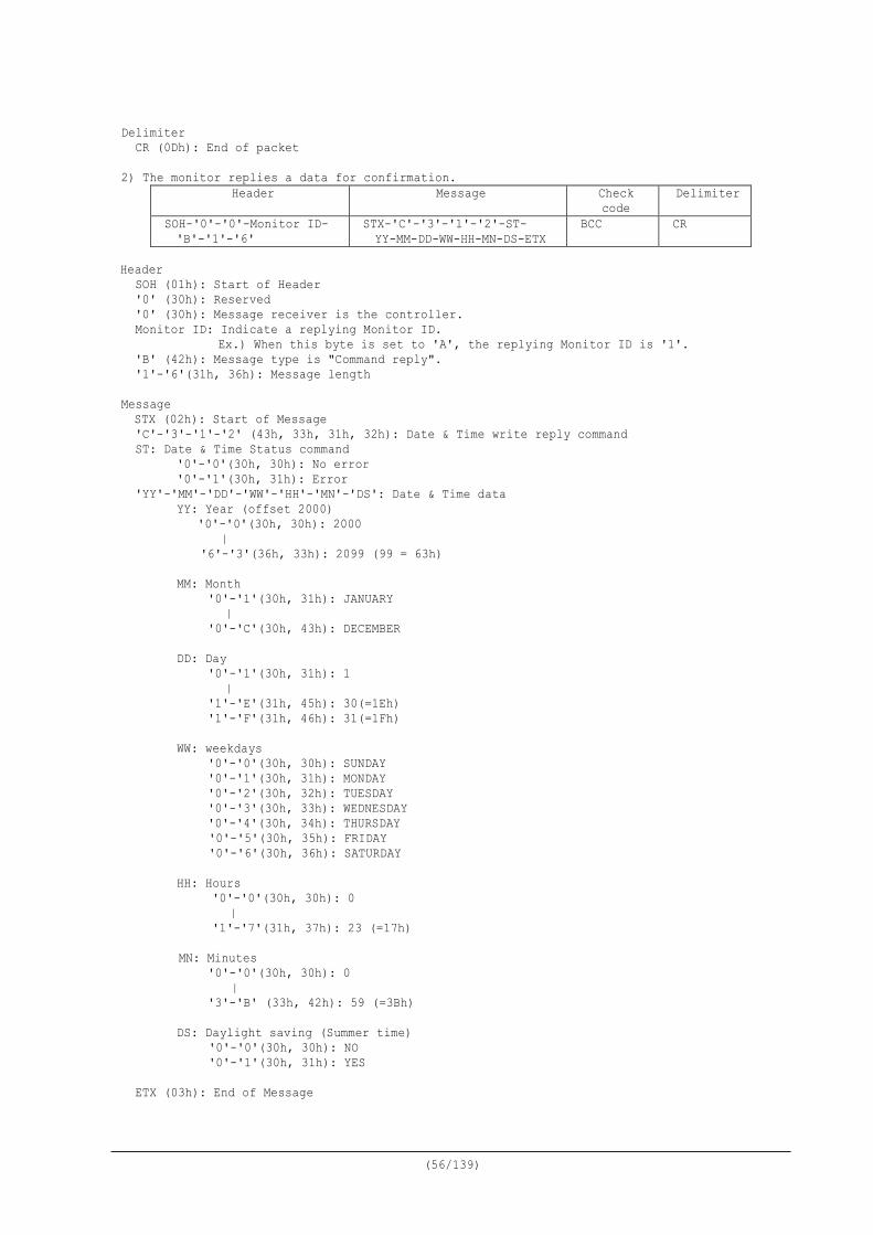
2) The monitor replies a data for confirmation. Header Message Check
code Delimiter
SOH-'0'-'0'-Monitor ID- 'B'-'1'-'6'
STX-'C'-'3'-'1'-'2'-ST- YY-MM-DD-WW-HH-MN-DS-ETX
BCC CR
Header
SOH (01h): Start of Header '0' (30h): Reserved '0' (30h): Message receiver is the controller. Monitor ID: Indicate a replying Monitor ID.
Ex.) When this byte is set to 'A', the replying Monitor ID is '1'. 'B' (42h): Message type is "Command reply". '1'-'6'(31h, 36h): Message length
Message STX (02h): Start of Message 'C'-'3'-'1'-'2' (43h, 33h, 31h, 32h): Date & Time write reply command ST: Date & Time Status command
'0'-'0'(30h, 30h): No error '0'-'1'(30h, 31h): Error
'YY'-'MM'-'DD'-'WW'-'HH'-'MN'-'DS': Date & Time data YY: Year (offset 2000)
'0'-'0'(30h, 30h): 2000 |
'6'-'3'(36h, 33h): 2099 (99 = 63h)
MM: Month '0'-'1'(30h, 31h): JANUARY | '0'-'C'(30h, 43h): DECEMBER
DD: Day '0'-'1'(30h, 31h): 1 | '1'-'E'(31h, 45h): 30(=1Eh) '1'-'F'(31h, 46h): 31(=1Fh)
WW: weekdays
'0'-'0'(30h, 30h): SUNDAY '0'-'1'(30h, 31h): MONDAY '0'-'2'(30h, 32h): TUESDAY '0'-'3'(30h, 33h): WEDNESDAY '0'-'4'(30h, 34h): THURSDAY '0'-'5'(30h, 35h): FRIDAY '0'-'6'(30h, 36h): SATURDAY
HH: Hours
'0'-'0'(30h, 30h): 0 | '1'-'7'(31h, 37h): 23 (=17h)
MN: Minutes
'0'-'0'(30h, 30h): 0 | '3'-'B' (33h, 42h): 59 (=3Bh)
DS: Daylight saving (Summer time)
'0'-'0'(30h, 30h): NO '0'-'1'(30h, 31h): YES
ETX (03h): End of Message

(57/139)
Check code
BCC: Block Check Code Refer to the section 4.3 “Check code” for a BCC calculation.
Delimiter
CR (0Dh): End of packet
(58/139)
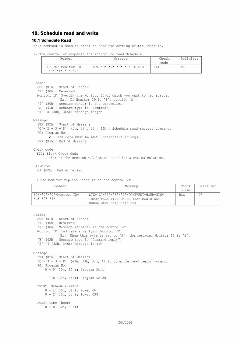
10. Schedule read and write 10.1 Schedule Read This command is used in order to read the setting of the Schedule. 1) The controller requests the monitor to read Schedule.
Header Message Check code
Delimiter
SOH-'0'-Monitor ID- '0'-'A'-'0'-'8'
STX-'C'-'2'-'3'-'D'-PG-ETX BCC CR
Header
SOH (01h): Start of Header '0' (30h): Reserved Monitor ID: Specify the Monitor ID of which you want to get status.
Ex.) If Monitor ID is '1', specify 'A'. '0' (30h): Message sender is the controller. 'A' (41h): Message type is "Command". '0'-'8'(30h, 38h): Message length
Message STX (02h): Start of Message 'C'-'2'-'3'-'D' (43h, 32h, 33h, 44h): Schedule read request command. PG: Program No.
The data must be ASCII characters strings. ETX (03h): End of Message
Check code BCC: Block Check Code
Refer to the section 4.3 “Check code” for a BCC calculation.
Delimiter CR (0Dh): End of packet
2) The monitor replies Schedule to the controller.
Header Message Check code
Delimiter
SOH-'0'-'0'-Monitor ID- 'B'-'2'-'4'
STX-'C'-'3'-'3'-'D'-PG-EVENT-HOUR-MIN- INPUT-WEEK-TYPE-PMODE-YEAR-MONTH-DAY-ORDER-EXT1-EXT2-EXT3-ETX
BCC CR
Header
SOH (01h): Start of Header '0' (30h): Reserved '0' (30h): Message receiver is the controller. Monitor ID: Indicate a replying Monitor ID.
Ex.) When this byte is set to 'A', the replying Monitor ID is '1'. 'B' (42h): Message type is "Command reply". '2'-'4'(32h, 34h): Message length
Message STX (02h): Start of Message 'C'-'3'-'3'-'D' (43h, 33h, 33h, 44h): Schedule read reply command PG: Program No.
'0'-'0'(30h, 30h): Program No.1 | '1'-'D'(31h, 44h): Program No.30
EVENT: Schedule event
'0'-'1'(30h, 31h): Power ON '0'-'2'(30h, 32h): Power OFF
HOUR: Time (hour)
'0'-'0'(30h, 30h): 00 |
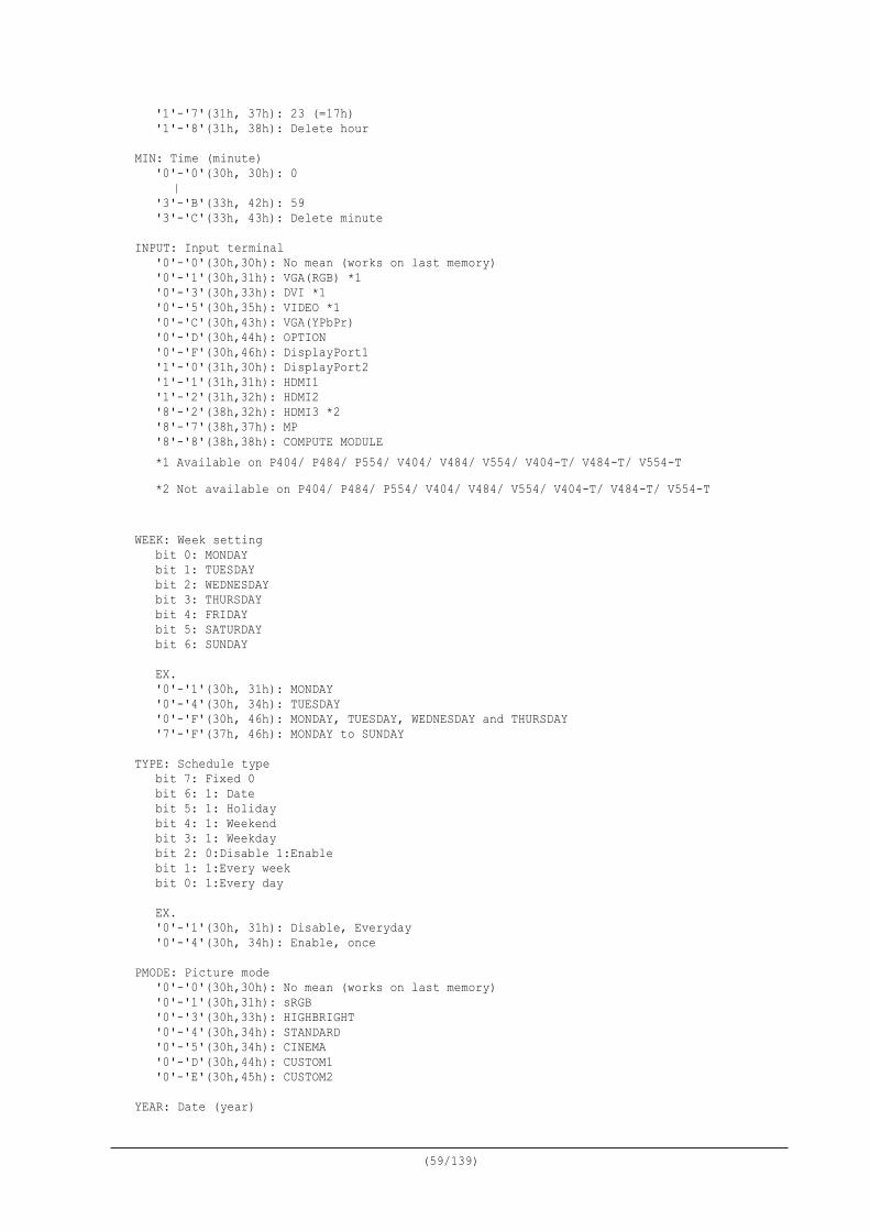
(59/139)
'1'-'7'(31h, 37h): 23 (=17h) '1'-'8'(31h, 38h): Delete hour
MIN: Time (minute) '0'-'0'(30h, 30h): 0 | '3'-'B'(33h, 42h): 59 '3'-'C'(33h, 43h): Delete minute
INPUT: Input terminal
'0'-'0'(30h,30h): No mean (works on last memory) '0'-'1'(30h,31h): VGA(RGB) *1 '0'-'3'(30h,33h): DVI *1 '0'-'5'(30h,35h): VIDEO *1 '0'-'C'(30h,43h): VGA(YPbPr) '0'-'D'(30h,44h): OPTION '0'-'F'(30h,46h): DisplayPort1 '1'-'0'(31h,30h): DisplayPort2 '1'-'1'(31h,31h): HDMI1 '1'-'2'(31h,32h): HDMI2 '8'-'2'(38h,32h): HDMI3 *2 '8'-'7'(38h,37h): MP '8'-'8'(38h,38h): COMPUTE MODULE *1 Available on P404/ P484/ P554/ V404/ V484/ V554/ V404-T/ V484-T/ V554-T *2 Not available on P404/ P484/ P554/ V404/ V484/ V554/ V404-T/ V484-T/ V554-T
WEEK: Week setting
bit 0: MONDAY bit 1: TUESDAY bit 2: WEDNESDAY bit 3: THURSDAY bit 4: FRIDAY bit 5: SATURDAY bit 6: SUNDAY
EX. '0'-'1'(30h, 31h): MONDAY '0'-'4'(30h, 34h): TUESDAY '0'-'F'(30h, 46h): MONDAY, TUESDAY, WEDNESDAY and THURSDAY '7'-'F'(37h, 46h): MONDAY to SUNDAY
TYPE: Schedule type
bit 7: Fixed 0 bit 6: 1: Date bit 5: 1: Holiday bit 4: 1: Weekend bit 3: 1: Weekday bit 2: 0:Disable 1:Enable bit 1: 1:Every week bit 0: 1:Every day EX. '0'-'1'(30h, 31h): Disable, Everyday '0'-'4'(30h, 34h): Enable, once
PMODE: Picture mode
'0'-'0'(30h,30h): No mean (works on last memory) '0'-'1'(30h,31h): sRGB '0'-'3'(30h,33h): HIGHBRIGHT '0'-'4'(30h,34h): STANDARD '0'-'5'(30h,34h): CINEMA '0'-'D'(30h,44h): CUSTOM1 '0'-'E'(30h,45h): CUSTOM2
YEAR: Date (year)

(60/139)
'0'-'0'(30h, 30h): 2000 | '6'-'3'(36h, 33h): 2099 '6'-'4'(36h, 34h): Delete year
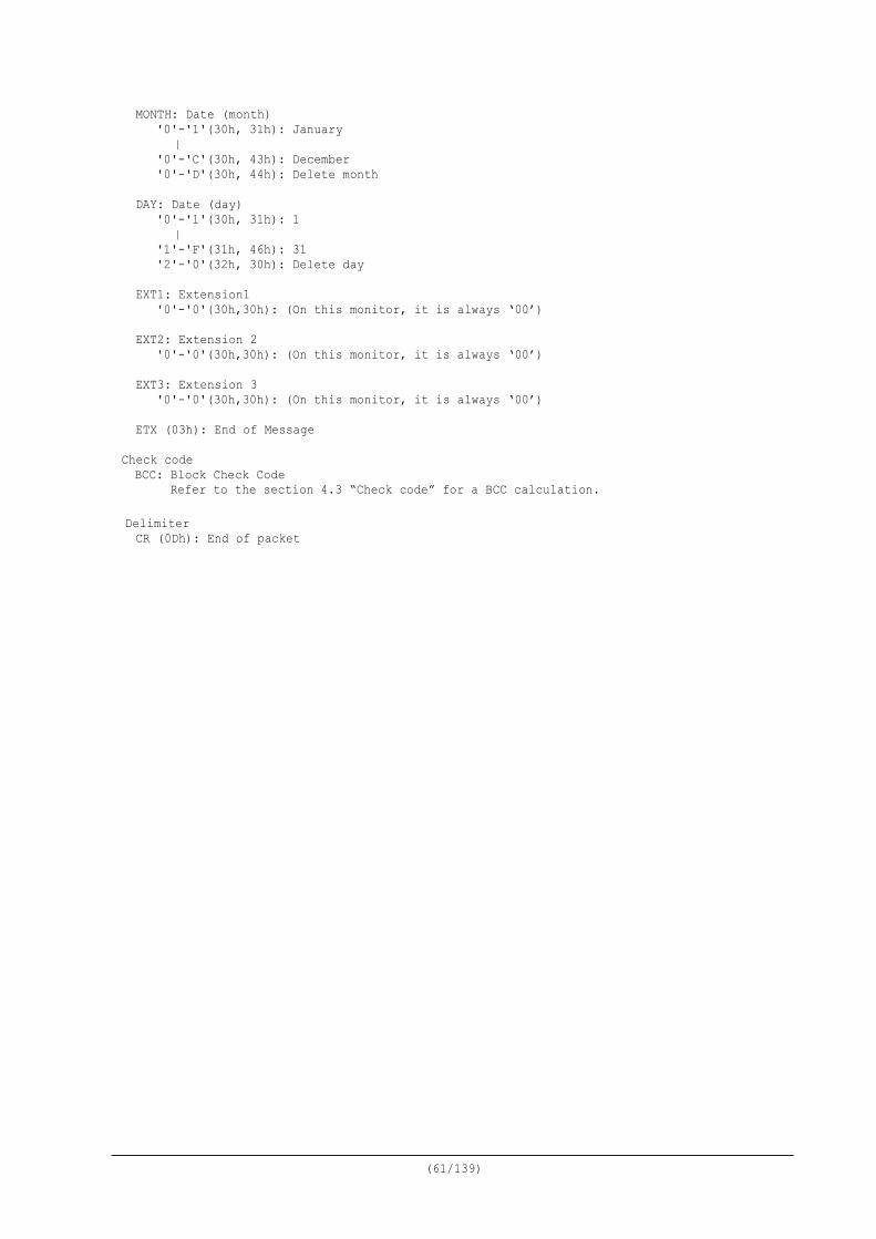
(61/139)
MONTH: Date (month) '0'-'1'(30h, 31h): January | '0'-'C'(30h, 43h): December '0'-'D'(30h, 44h): Delete month
DAY: Date (day)
'0'-'1'(30h, 31h): 1 | '1'-'F'(31h, 46h): 31 '2'-'0'(32h, 30h): Delete day
EXT1: Extension1
'0'-'0'(30h,30h): (On this monitor, it is always ‘00’)
EXT2: Extension 2 '0'-'0'(30h,30h): (On this monitor, it is always ‘00’)
EXT3: Extension 3
'0'-'0'(30h,30h): (On this monitor, it is always ‘00’)
ETX (03h): End of Message Check code BCC: Block Check Code Refer to the section 4.3 “Check code” for a BCC calculation.
Delimiter CR (0Dh): End of packet
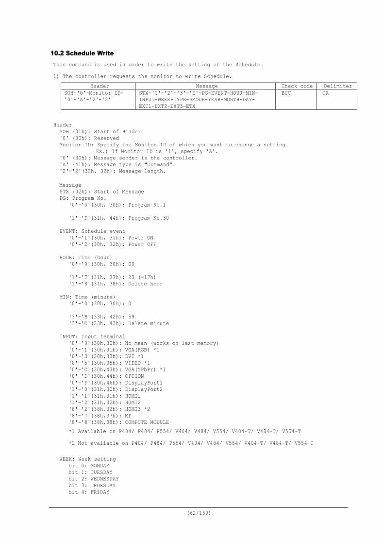
(62/139)
10.2 Schedule Write This command is used in order to write the setting of the Schedule. 1) The controller requests the monitor to write Schedule.
Header Message Check code Delimiter SOH-'0'-Monitor ID- '0'-'A'-'2'-'2'
STX-'C'-'2'-'3'-'E'-PG-EVENT-HOUR-MIN- INPUT-WEEK-TYPE-PMODE-YEAR-MONTH-DAY- EXT1-EXT2-EXT3-ETX
BCC CR
Header
SOH (01h): Start of Header '0' (30h): Reserved Monitor ID: Specify the Monitor ID of which you want to change a setting.
Ex.) If Monitor ID is '1', specify 'A'. '0' (30h): Message sender is the controller. 'A' (41h): Message type is "Command". '2'-'2'(32h, 32h): Message length. Message STX (02h): Start of Message PG: Program No.
'0'-'0'(30h, 30h): Program No.1 | '1'-'D'(31h, 44h): Program No.30
EVENT: Schedule event
'0'-'1'(30h, 31h): Power ON '0'-'2'(30h, 32h): Power OFF
HOUR: Time (hour)
'0'-'0'(30h, 30h): 00 | '1'-'7'(31h, 37h): 23 (=17h) '1'-'8'(31h, 38h): Delete hour
MIN: Time (minute) '0'-'0'(30h, 30h): 0 | '3'-'B'(33h, 42h): 59 '3'-'C'(33h, 43h): Delete minute
INPUT: Input terminal
'0'-'0'(30h,30h): No mean (works on last memory) '0'-'1'(30h,31h): VGA(RGB) *1 '0'-'3'(30h,33h): DVI *1 '0'-'5'(30h,35h): VIDEO *1 '0'-'C'(30h,43h): VGA(YPbPr) *1 '0'-'D'(30h,44h): OPTION '0'-'F'(30h,46h): DisplayPort1 '1'-'0'(31h,30h): DisplayPort2 '1'-'1'(31h,31h): HDMI1 '1'-'2'(31h,32h): HDMI2 '8'-'2'(38h,32h): HDMI3 *2 '8'-'7'(38h,37h): MP '8'-'8'(38h,38h): COMPUTE MODULE *1 Available on P404/ P484/ P554/ V404/ V484/ V554/ V404-T/ V484-T/ V554-T *2 Not available on P404/ P484/ P554/ V404/ V484/ V554/ V404-T/ V484-T/ V554-T
WEEK: Week setting
bit 0: MONDAY bit 1: TUESDAY bit 2: WEDNESDAY bit 3: THURSDAY bit 4: FRIDAY
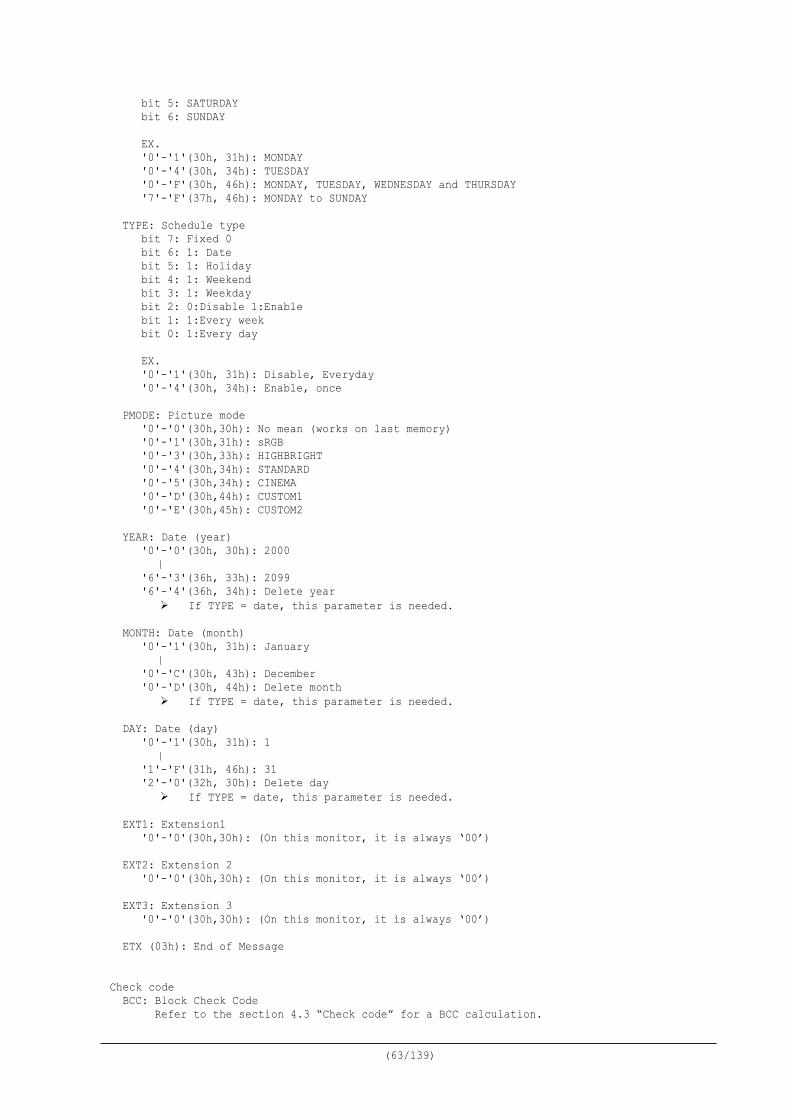
(63/139)
bit 5: SATURDAY bit 6: SUNDAY
EX. '0'-'1'(30h, 31h): MONDAY '0'-'4'(30h, 34h): TUESDAY '0'-'F'(30h, 46h): MONDAY, TUESDAY, WEDNESDAY and THURSDAY '7'-'F'(37h, 46h): MONDAY to SUNDAY
TYPE: Schedule type
bit 7: Fixed 0 bit 6: 1: Date bit 5: 1: Holiday bit 4: 1: Weekend bit 3: 1: Weekday bit 2: 0:Disable 1:Enable bit 1: 1:Every week bit 0: 1:Every day EX. '0'-'1'(30h, 31h): Disable, Everyday '0'-'4'(30h, 34h): Enable, once
PMODE: Picture mode
'0'-'0'(30h,30h): No mean (works on last memory) '0'-'1'(30h,31h): sRGB '0'-'3'(30h,33h): HIGHBRIGHT '0'-'4'(30h,34h): STANDARD '0'-'5'(30h,34h): CINEMA '0'-'D'(30h,44h): CUSTOM1 '0'-'E'(30h,45h): CUSTOM2
YEAR: Date (year)
'0'-'0'(30h, 30h): 2000 | '6'-'3'(36h, 33h): 2099 '6'-'4'(36h, 34h): Delete year If TYPE = date, this parameter is needed.
MONTH: Date (month)
'0'-'1'(30h, 31h): January | '0'-'C'(30h, 43h): December '0'-'D'(30h, 44h): Delete month If TYPE = date, this parameter is needed.
DAY: Date (day)
'0'-'1'(30h, 31h): 1 | '1'-'F'(31h, 46h): 31 '2'-'0'(32h, 30h): Delete day If TYPE = date, this parameter is needed.
EXT1: Extension1
'0'-'0'(30h,30h): (On this monitor, it is always ‘00’)
EXT2: Extension 2 '0'-'0'(30h,30h): (On this monitor, it is always ‘00’)
EXT3: Extension 3
'0'-'0'(30h,30h): (On this monitor, it is always ‘00’)
ETX (03h): End of Message
Check code
BCC: Block Check Code Refer to the section 4.3 “Check code” for a BCC calculation.

(64/139)
Delimiter
CR (0Dh): End of packet
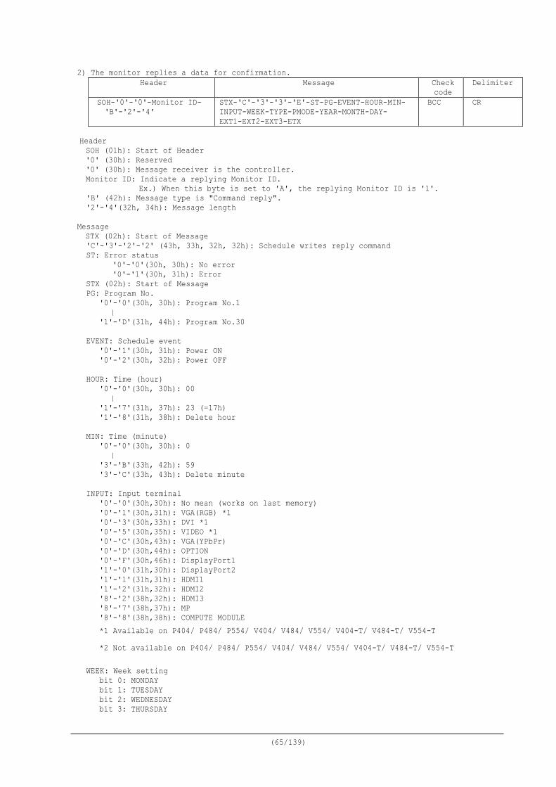
(65/139)
2) The monitor replies a data for confirmation. Header Message Check
code Delimiter
SOH-'0'-'0'-Monitor ID- 'B'-'2'-'4'
STX-'C'-'3'-'3'-'E'-ST-PG-EVENT-HOUR-MIN- INPUT-WEEK-TYPE-PMODE-YEAR-MONTH-DAY- EXT1-EXT2-EXT3-ETX
BCC CR
Header SOH (01h): Start of Header '0' (30h): Reserved '0' (30h): Message receiver is the controller. Monitor ID: Indicate a replying Monitor ID.
Ex.) When this byte is set to 'A', the replying Monitor ID is '1'. 'B' (42h): Message type is "Command reply". '2'-'4'(32h, 34h): Message length
Message STX (02h): Start of Message 'C'-'3'-'2'-'2' (43h, 33h, 32h, 32h): Schedule writes reply command ST: Error status
'0'-'0'(30h, 30h): No error '0'-'1'(30h, 31h): Error
STX (02h): Start of Message PG: Program No.
'0'-'0'(30h, 30h): Program No.1 | '1'-'D'(31h, 44h): Program No.30
EVENT: Schedule event
'0'-'1'(30h, 31h): Power ON '0'-'2'(30h, 32h): Power OFF
HOUR: Time (hour)
'0'-'0'(30h, 30h): 00 | '1'-'7'(31h, 37h): 23 (=17h) '1'-'8'(31h, 38h): Delete hour
MIN: Time (minute) '0'-'0'(30h, 30h): 0 | '3'-'B'(33h, 42h): 59 '3'-'C'(33h, 43h): Delete minute
INPUT: Input terminal
'0'-'0'(30h,30h): No mean (works on last memory) '0'-'1'(30h,31h): VGA(RGB) *1 '0'-'3'(30h,33h): DVI *1 '0'-'5'(30h,35h): VIDEO *1 '0'-'C'(30h,43h): VGA(YPbPr) '0'-'D'(30h,44h): OPTION '0'-'F'(30h,46h): DisplayPort1 '1'-'0'(31h,30h): DisplayPort2 '1'-'1'(31h,31h): HDMI1 '1'-'2'(31h,32h): HDMI2 '8'-'2'(38h,32h): HDMI3 '8'-'7'(38h,37h): MP '8'-'8'(38h,38h): COMPUTE MODULE *1 Available on P404/ P484/ P554/ V404/ V484/ V554/ V404-T/ V484-T/ V554-T *2 Not available on P404/ P484/ P554/ V404/ V484/ V554/ V404-T/ V484-T/ V554-T
WEEK: Week setting
bit 0: MONDAY bit 1: TUESDAY bit 2: WEDNESDAY bit 3: THURSDAY
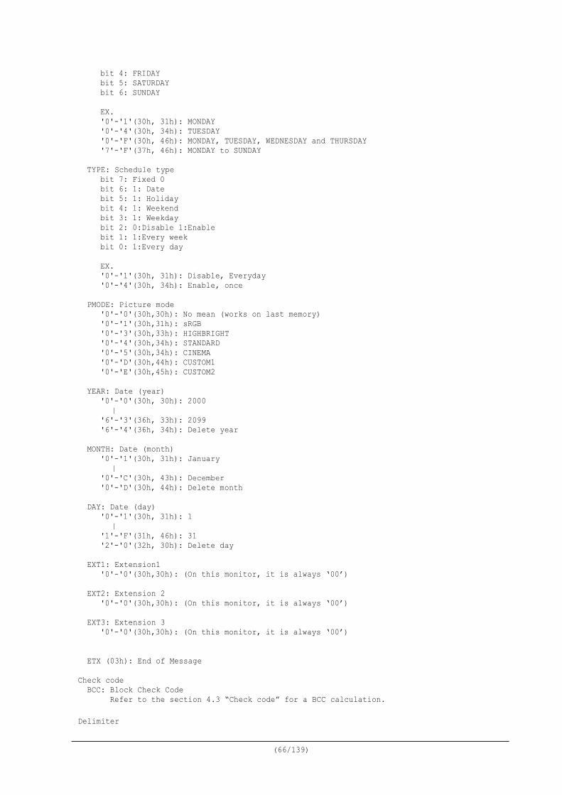
(66/139)
bit 4: FRIDAY bit 5: SATURDAY bit 6: SUNDAY
EX. '0'-'1'(30h, 31h): MONDAY '0'-'4'(30h, 34h): TUESDAY '0'-'F'(30h, 46h): MONDAY, TUESDAY, WEDNESDAY and THURSDAY '7'-'F'(37h, 46h): MONDAY to SUNDAY
TYPE: Schedule type
bit 7: Fixed 0 bit 6: 1: Date bit 5: 1: Holiday bit 4: 1: Weekend bit 3: 1: Weekday bit 2: 0:Disable 1:Enable bit 1: 1:Every week bit 0: 1:Every day EX. '0'-'1'(30h, 31h): Disable, Everyday '0'-'4'(30h, 34h): Enable, once
PMODE: Picture mode
'0'-'0'(30h,30h): No mean (works on last memory) '0'-'1'(30h,31h): sRGB '0'-'3'(30h,33h): HIGHBRIGHT '0'-'4'(30h,34h): STANDARD '0'-'5'(30h,34h): CINEMA '0'-'D'(30h,44h): CUSTOM1 '0'-'E'(30h,45h): CUSTOM2
YEAR: Date (year)
'0'-'0'(30h, 30h): 2000 | '6'-'3'(36h, 33h): 2099 '6'-'4'(36h, 34h): Delete year
MONTH: Date (month)
'0'-'1'(30h, 31h): January | '0'-'C'(30h, 43h): December '0'-'D'(30h, 44h): Delete month
DAY: Date (day)
'0'-'1'(30h, 31h): 1 | '1'-'F'(31h, 46h): 31 '2'-'0'(32h, 30h): Delete day
EXT1: Extension1
'0'-'0'(30h,30h): (On this monitor, it is always ‘00’)
EXT2: Extension 2 '0'-'0'(30h,30h): (On this monitor, it is always ‘00’)
EXT3: Extension 3
'0'-'0'(30h,30h): (On this monitor, it is always ‘00’)
ETX (03h): End of Message Check code
BCC: Block Check Code Refer to the section 4.3 “Check code” for a BCC calculation.
Delimiter

(67/139)
CR (0Dh): End of packet
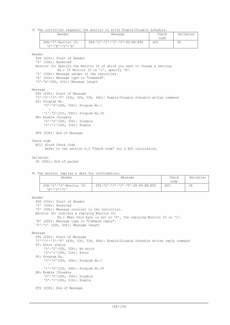
(68/139)
3) The controller requests the monitor to write Enable/Disable Schedule. Header Message Check
code Delimiter
SOH-'0'-Monitor ID- '0'-'A'-'0'-'A'
STX-'C'-'2'-'3'-'F'-PG-EN-ETX BCC CR
Header
SOH (01h): Start of Header '0' (30h): Reserved Monitor ID: Specify the Monitor ID of which you want to change a setting.
Ex.) If Monitor ID is '1', specify 'A'. '0' (30h): Message sender is the controller. 'A' (41h): Message type is "Command". '0'-'A'(30h, 41h): Message length
Message STX (02h): Start of Message 'C'-'2'-'3'-'F' (43h, 32h, 33h, 46h): Enable/Disable Schedule writes command PG: Program No.
'0'-'0'(30h, 30h): Program No.1 | '1'-'D'(31h, 44h): Program No.30
EN: Enable /Disable '0'-'0'(30h, 30h): Disable '0'-'1'(30h, 31h): Enable
ETX (03h): End of Message
Check code
BCC: Block Check Code Refer to the section 4.3 “Check code” for a BCC calculation.
Delimiter
CR (0Dh): End of packet 4) The monitor replies a data for confirmation.
Header Message Check code
Delimiter
SOH-'0'-'0'-Monitor ID- 'B'-'0'-'C'
STX-'C'-'3'-'3'-'F'-ST-PG-EN-ETX BCC CR
Header
SOH (01h): Start of Header '0' (30h): Reserved '0' (30h): Message receiver is the controller. Monitor ID: Indicate a replying Monitor ID.
Ex.) When this byte is set to 'A', the replying Monitor ID is '1'. 'B' (42h): Message type is "Command reply". '0'-'C' (30h, 43h): Message length
Message STX (02h): Start of Message 'C'-'3'-'3'-'F' (43h, 33h, 33h, 46h): Enable/Disable Schedule writes reply command ST: Error status
'0'-'0'(30h, 30h): No error '0'-'1'(30h, 31h): Error
PG: Program No. '0'-'0'(30h, 30h): Program No.1 | '1'-'D'(31h, 44h): Program No.30
EN: Enable /Disable '0'-'0'(30h, 30h): Disable '0'-'1'(30h, 31h): Enable
ETX (03h): End of Message

(69/139)
Check code BCC: Block Check Code Refer to the section 4.3 “Check code” for a BCC calculation.
Delimiter
CR (0Dh): End of packet
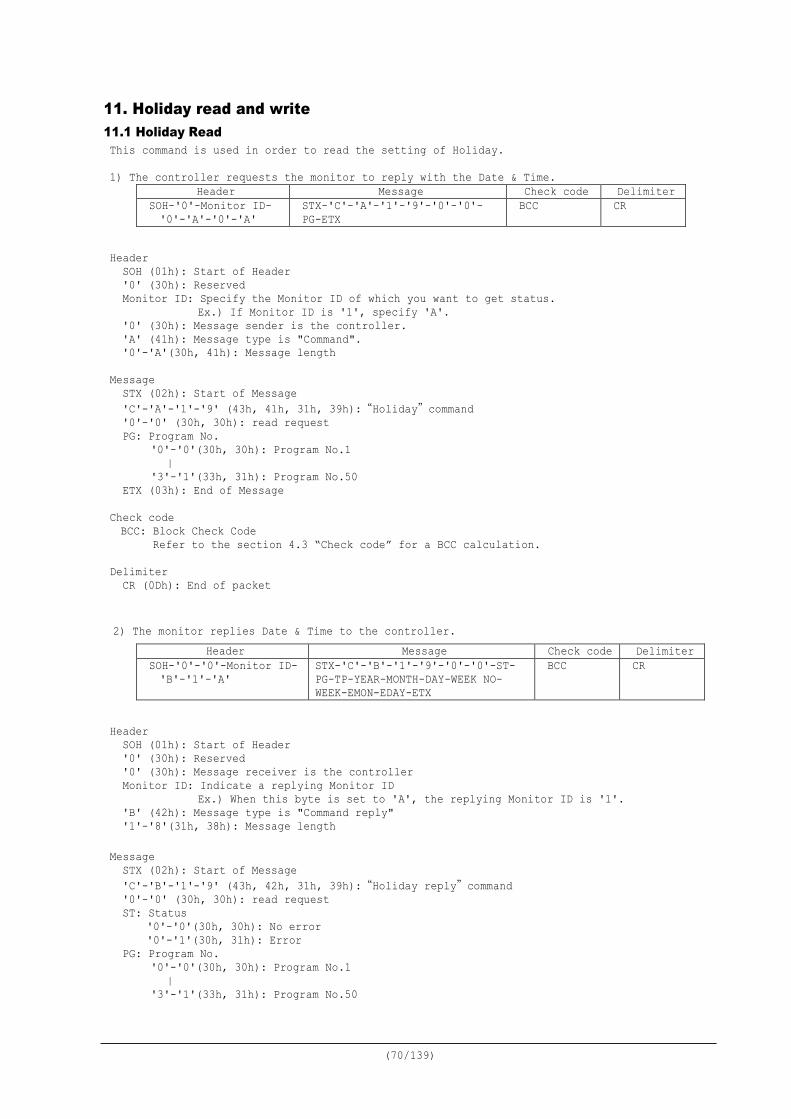
(70/139)
11. Holiday read and write 11.1 Holiday Read This command is used in order to read the setting of Holiday. 1) The controller requests the monitor to reply with the Date & Time.
Header Message Check code Delimiter SOH-'0'-Monitor ID- '0'-'A'-'0'-'A'
STX-'C'-'A'-'1'-'9'-'0'-'0'-PG-ETX
BCC CR
Header
SOH (01h): Start of Header '0' (30h): Reserved Monitor ID: Specify the Monitor ID of which you want to get status.
Ex.) If Monitor ID is '1', specify 'A'. '0' (30h): Message sender is the controller. 'A' (41h): Message type is "Command". '0'-'A'(30h, 41h): Message length
Message STX (02h): Start of Message 'C'-'A'-'1'-'9' (43h, 41h, 31h, 39h):“Holiday”command '0'-'0' (30h, 30h): read request PG: Program No.
'0'-'0'(30h, 30h): Program No.1 | '3'-'1'(33h, 31h): Program No.50
ETX (03h): End of Message
Check code BCC: Block Check Code Refer to the section 4.3 “Check code” for a BCC calculation.
Delimiter
CR (0Dh): End of packet 2) The monitor replies Date & Time to the controller.
Header Message Check code Delimiter SOH-'0'-'0'-Monitor ID- 'B'-'1'-'A'
STX-'C'-'B'-'1'-'9'-'0'-'0'-ST- PG-TP-YEAR-MONTH-DAY-WEEK NO- WEEK-EMON-EDAY-ETX
BCC CR
Header
SOH (01h): Start of Header '0' (30h): Reserved '0' (30h): Message receiver is the controller Monitor ID: Indicate a replying Monitor ID
Ex.) When this byte is set to 'A', the replying Monitor ID is '1'. 'B' (42h): Message type is "Command reply" '1'-'8'(31h, 38h): Message length
Message STX (02h): Start of Message 'C'-'B'-'1'-'9' (43h, 42h, 31h, 39h):“Holiday reply”command '0'-'0' (30h, 30h): read request ST: Status
'0'-'0'(30h, 30h): No error '0'-'1'(30h, 31h): Error
PG: Program No. '0'-'0'(30h, 30h): Program No.1 | '3'-'1'(33h, 31h): Program No.50
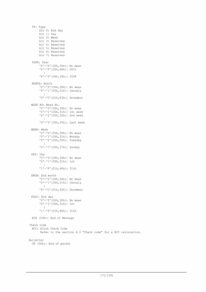
(71/139)
TP: Type bit 0: End day bit 1: Day bit 2: Week bit 3: Reserved bit 4: Reserved bit 5: Reserved bit 6: Reserved bit 7: Reserved
YEAR: Year
'0'-'0'(30h,30h): No mean '0'-'F'(30h,46h): 2015 | '6'-'3'(36h,33h): 2099
MONTH: Month
'0'-'0'(30h,30h): No mean '0'-'1'(30h,31h): Janualy | '0'-'C'(31h,43h): December
WEEK NO: Week No.
'0'-'0'(30h,30h): No mean '0'-'1'(30h,31h): 1st week '0'-'2'(30h,32h): 2nd week | '0'-'5'(30h,35h): Last week
WEEK: Week
'0'-'0'(30h,30h): No mean '0'-'1'(30h,31h): Monday '0'-'2'(30h,32h): Tuesday | '0'-'7'(30h,37h): Sunday
DAY: Day
'0'-'0'(30h,30h): No mean '0'-'1'(30h,31h): 1st | '1'-'F'(31h,46h): 31th
EMON: End month
'0'-'0'(30h,30h): No mean '0'-'1'(30h,31h): Janualy | '0'-'C'(31h,43h): December
EDAY: End day '0'-'0'(30h,30h): No mean '0'-'1'(30h,31h): 1st | '1'-'F'(31h,46h): 31th
ETX (03h): End of Message Check code BCC: Block Check Code Refer to the section 4.3 “Check code” for a BCC calculation.
Delimiter
CR (0Dh): End of packet
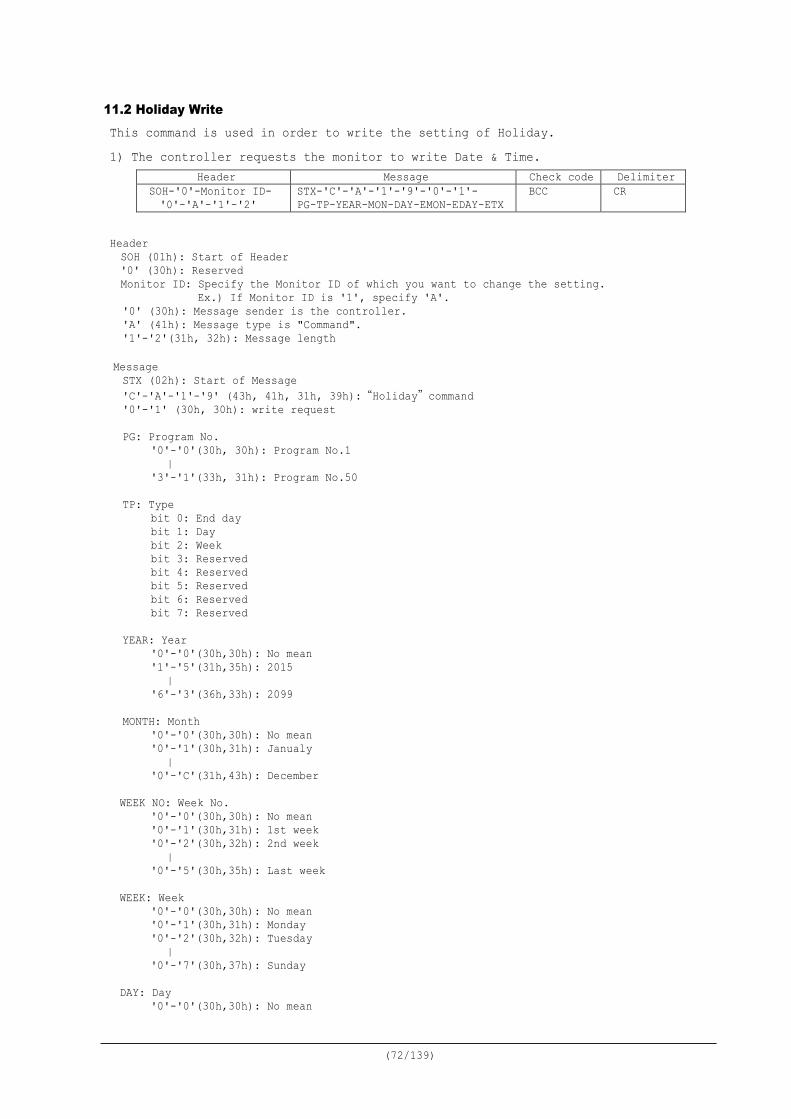
(72/139)
11.2 Holiday Write This command is used in order to write the setting of Holiday. 1) The controller requests the monitor to write Date & Time.
Header Message Check code Delimiter SOH-'0'-Monitor ID- '0'-'A'-'1'-'2'
STX-'C'-'A'-'1'-'9'-'0'-'1'- PG-TP-YEAR-MON-DAY-EMON-EDAY-ETX
BCC CR
Header SOH (01h): Start of Header '0' (30h): Reserved Monitor ID: Specify the Monitor ID of which you want to change the setting.
Ex.) If Monitor ID is '1', specify 'A'. '0' (30h): Message sender is the controller. 'A' (41h): Message type is "Command". '1'-'2'(31h, 32h): Message length
Message STX (02h): Start of Message 'C'-'A'-'1'-'9' (43h, 41h, 31h, 39h):“Holiday”command '0'-'1' (30h, 30h): write request PG: Program No.
'0'-'0'(30h, 30h): Program No.1 | '3'-'1'(33h, 31h): Program No.50
TP: Type bit 0: End day bit 1: Day bit 2: Week bit 3: Reserved bit 4: Reserved bit 5: Reserved bit 6: Reserved bit 7: Reserved
YEAR: Year
'0'-'0'(30h,30h): No mean '1'-'5'(31h,35h): 2015 | '6'-'3'(36h,33h): 2099
MONTH: Month
'0'-'0'(30h,30h): No mean '0'-'1'(30h,31h): Janualy | '0'-'C'(31h,43h): December
WEEK NO: Week No.
'0'-'0'(30h,30h): No mean '0'-'1'(30h,31h): 1st week '0'-'2'(30h,32h): 2nd week | '0'-'5'(30h,35h): Last week
WEEK: Week
'0'-'0'(30h,30h): No mean '0'-'1'(30h,31h): Monday '0'-'2'(30h,32h): Tuesday | '0'-'7'(30h,37h): Sunday
DAY: Day
'0'-'0'(30h,30h): No mean
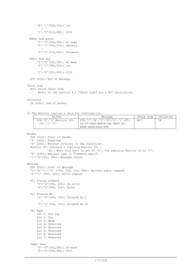
(73/139)
'0'-'1'(30h,31h): 1st | '1'-'F'(31h,46h): 31th
EMON: End month
'0'-'0'(30h,30h): No mean '0'-'1'(30h,31h): Janualy | '0'-'C'(31h,43h): December
EDAY: End day '0'-'0'(30h,30h): No mean '0'-'1'(30h,31h): 1st | '1'-'F'(31h,46h): 31th
ETX (03h): End of Message
Check code
BCC: Block Check Code Refer to the section 4.3 “Check code” for a BCC calculation.
Delimiter
CR (0Dh): End of packet
2) The monitor replies a data for confirmation.
Header Message Check code Delimiter SOH-'0'-'0'-Monitor ID- 'B'-'1'-'C'
STX-'C'-'B'-'1'-'9'-'0'-'1'-ST- PG-TP-YEAR-MONTH-DAY-WEEK NO- WEEK-EMON-EDAY-ETX
BCC CR
Header
SOH (01h): Start of Header '0' (30h): Reserved '0' (30h): Message receiver is the controller. Monitor ID: Indicate a replying Monitor ID.
Ex.) When this byte is set to 'A', the replying Monitor ID is '1'. 'B' (42h): Message type is "Command reply". '1'-'8'(31h, 38h): Message length
Message STX (02h): Start of Message 'C'-'B'-'1'-'9' (43h, 33h, 31h, 39h): Holiday reply command '0'-'1' (30h, 30h): write request ST: Status command
'0'-'0'(30h, 30h): No error '0'-'1'(30h, 31h): Error
PG: Program No. '0'-'0'(30h, 30h): Program No.1 | '3'-'1'(33h, 31h): Program No.50
TP: Type bit 0: End day bit 1: Day bit 2: Week bit 3: Reserved bit 4: Reserved bit 5: Reserved bit 6: Reserved bit 7: Reserved
YEAR: Year
'0'-'0'(30h,30h): No mean '0'-'F'(30h,46h): 2015
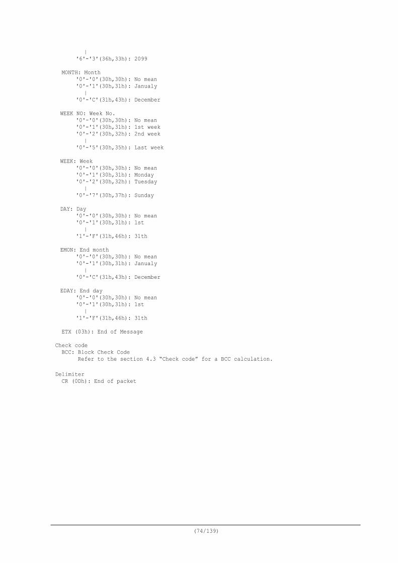
(74/139)
| '6'-'3'(36h,33h): 2099
MONTH: Month
'0'-'0'(30h,30h): No mean '0'-'1'(30h,31h): Janualy | '0'-'C'(31h,43h): December
WEEK NO: Week No.
'0'-'0'(30h,30h): No mean '0'-'1'(30h,31h): 1st week '0'-'2'(30h,32h): 2nd week | '0'-'5'(30h,35h): Last week
WEEK: Week
'0'-'0'(30h,30h): No mean '0'-'1'(30h,31h): Monday '0'-'2'(30h,32h): Tuesday | '0'-'7'(30h,37h): Sunday
DAY: Day
'0'-'0'(30h,30h): No mean '0'-'1'(30h,31h): 1st | '1'-'F'(31h,46h): 31th
EMON: End month
'0'-'0'(30h,30h): No mean '0'-'1'(30h,31h): Janualy | '0'-'C'(31h,43h): December
EDAY: End day '0'-'0'(30h,30h): No mean '0'-'1'(30h,31h): 1st | '1'-'F'(31h,46h): 31th
ETX (03h): End of Message
Check code
BCC: Block Check Code Refer to the section 4.3 “Check code” for a BCC calculation.
Delimiter
CR (0Dh): End of packet
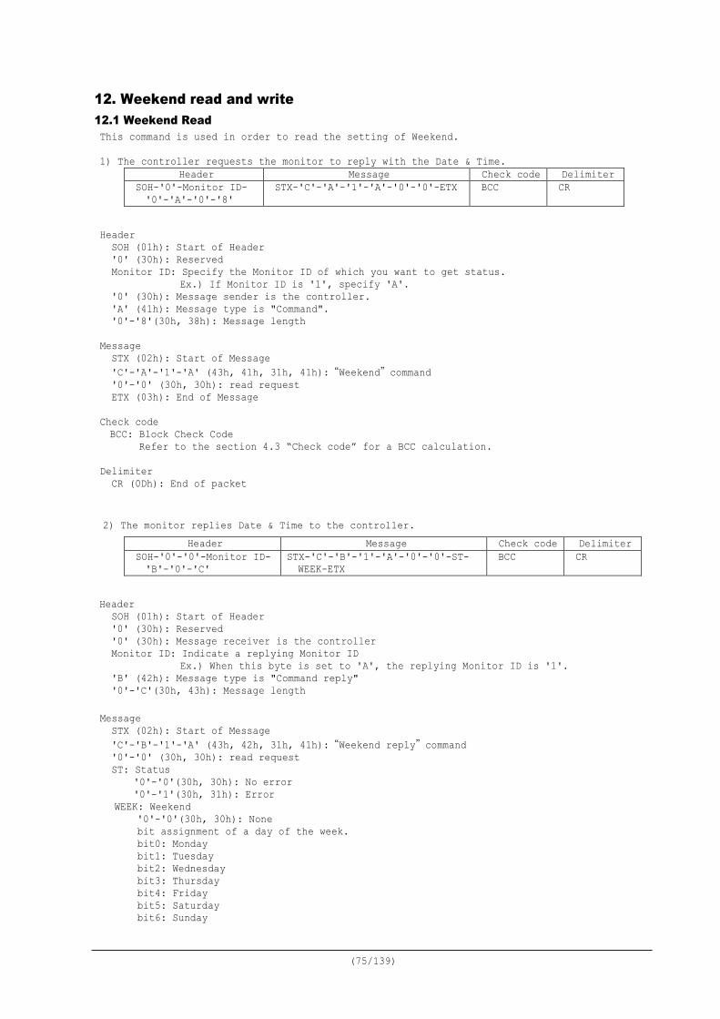
(75/139)
12. Weekend read and write 12.1 Weekend Read This command is used in order to read the setting of Weekend. 1) The controller requests the monitor to reply with the Date & Time.
Header Message Check code Delimiter SOH-'0'-Monitor ID- '0'-'A'-'0'-'8'
STX-'C'-'A'-'1'-'A'-'0'-'0'-ETX BCC CR
Header
SOH (01h): Start of Header '0' (30h): Reserved Monitor ID: Specify the Monitor ID of which you want to get status.
Ex.) If Monitor ID is '1', specify 'A'. '0' (30h): Message sender is the controller. 'A' (41h): Message type is "Command". '0'-'8'(30h, 38h): Message length
Message STX (02h): Start of Message 'C'-'A'-'1'-'A' (43h, 41h, 31h, 41h):“Weekend”command '0'-'0' (30h, 30h): read request ETX (03h): End of Message
Check code BCC: Block Check Code Refer to the section 4.3 “Check code” for a BCC calculation.
Delimiter
CR (0Dh): End of packet 2) The monitor replies Date & Time to the controller.
Header Message Check code Delimiter SOH-'0'-'0'-Monitor ID- 'B'-'0'-'C'
STX-'C'-'B'-'1'-'A'-'0'-'0'-ST- WEEK-ETX
BCC CR
Header
SOH (01h): Start of Header '0' (30h): Reserved '0' (30h): Message receiver is the controller Monitor ID: Indicate a replying Monitor ID
Ex.) When this byte is set to 'A', the replying Monitor ID is '1'. 'B' (42h): Message type is "Command reply" '0'-'C'(30h, 43h): Message length
Message STX (02h): Start of Message 'C'-'B'-'1'-'A' (43h, 42h, 31h, 41h):“Weekend reply”command '0'-'0' (30h, 30h): read request ST: Status
'0'-'0'(30h, 30h): No error '0'-'1'(30h, 31h): Error
WEEK: Weekend '0'-'0'(30h, 30h): None bit assignment of a day of the week. bit0: Monday bit1: Tuesday bit2: Wednesday bit3: Thursday bit4: Friday bit5: Saturday bit6: Sunday
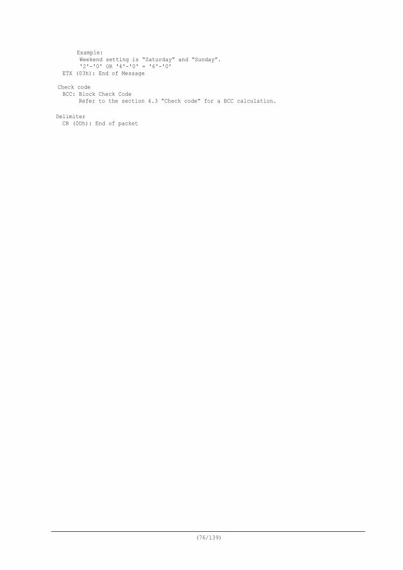
(76/139)
Example: Weekend setting is “Saturday” and “Sunday”. '2'-'0' OR '4'-'0' = '6'-'0'
ETX (03h): End of Message Check code BCC: Block Check Code Refer to the section 4.3 “Check code” for a BCC calculation.
Delimiter
CR (0Dh): End of packet
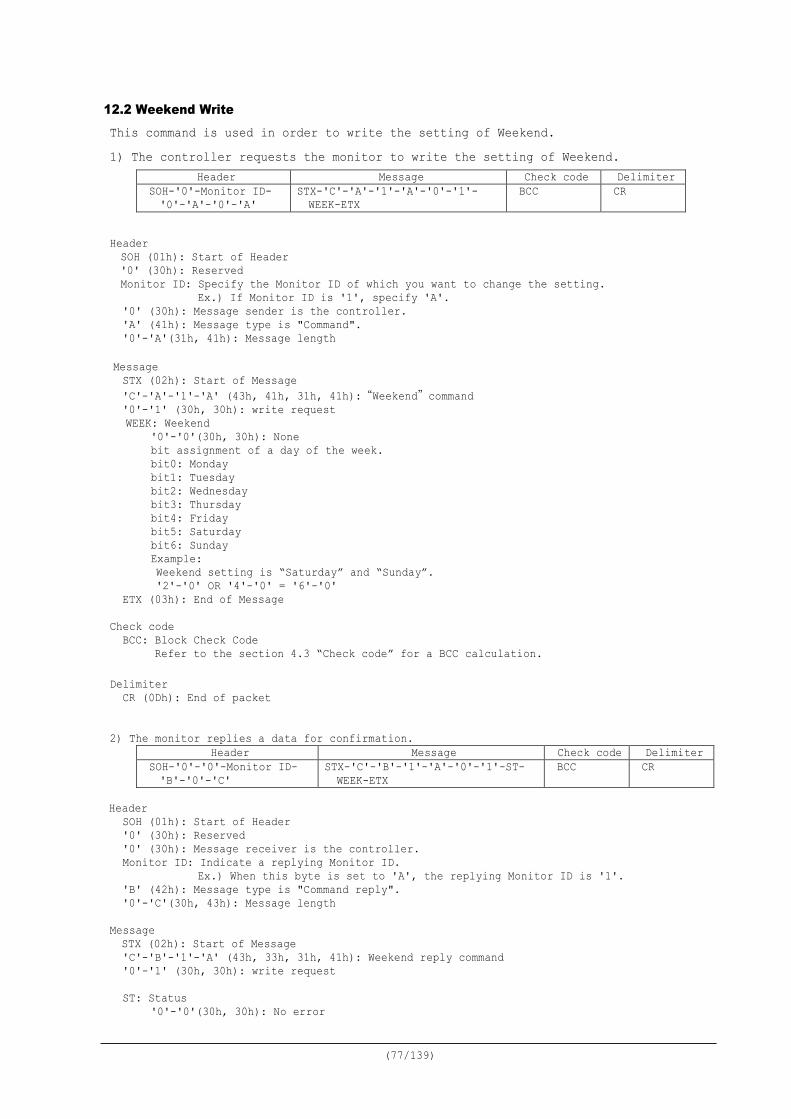
(77/139)
12.2 Weekend Write This command is used in order to write the setting of Weekend. 1) The controller requests the monitor to write the setting of Weekend.
Header Message Check code Delimiter SOH-'0'-Monitor ID- '0'-'A'-'0'-'A'
STX-'C'-'A'-'1'-'A'-'0'-'1'- WEEK-ETX
BCC CR
Header SOH (01h): Start of Header '0' (30h): Reserved Monitor ID: Specify the Monitor ID of which you want to change the setting.
Ex.) If Monitor ID is '1', specify 'A'. '0' (30h): Message sender is the controller. 'A' (41h): Message type is "Command". '0'-'A'(31h, 41h): Message length
Message STX (02h): Start of Message 'C'-'A'-'1'-'A' (43h, 41h, 31h, 41h):“Weekend”command '0'-'1' (30h, 30h): write request WEEK: Weekend
'0'-'0'(30h, 30h): None bit assignment of a day of the week. bit0: Monday bit1: Tuesday bit2: Wednesday bit3: Thursday bit4: Friday bit5: Saturday bit6: Sunday Example: Weekend setting is “Saturday” and “Sunday”. '2'-'0' OR '4'-'0' = '6'-'0'
ETX (03h): End of Message Check code
BCC: Block Check Code Refer to the section 4.3 “Check code” for a BCC calculation.
Delimiter
CR (0Dh): End of packet
2) The monitor replies a data for confirmation.
Header Message Check code Delimiter SOH-'0'-'0'-Monitor ID- 'B'-'0'-'C'
STX-'C'-'B'-'1'-'A'-'0'-'1'-ST- WEEK-ETX
BCC CR
Header
SOH (01h): Start of Header '0' (30h): Reserved '0' (30h): Message receiver is the controller. Monitor ID: Indicate a replying Monitor ID.
Ex.) When this byte is set to 'A', the replying Monitor ID is '1'. 'B' (42h): Message type is "Command reply". '0'-'C'(30h, 43h): Message length
Message STX (02h): Start of Message 'C'-'B'-'1'-'A' (43h, 33h, 31h, 41h): Weekend reply command '0'-'1' (30h, 30h): write request ST: Status
'0'-'0'(30h, 30h): No error
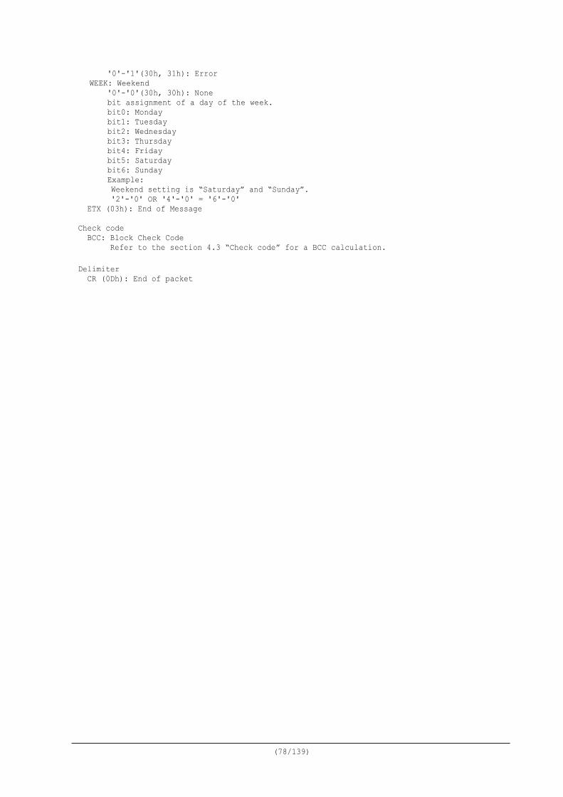
(78/139)
'0'-'1'(30h, 31h): Error WEEK: Weekend
'0'-'0'(30h, 30h): None bit assignment of a day of the week. bit0: Monday bit1: Tuesday bit2: Wednesday bit3: Thursday bit4: Friday bit5: Saturday bit6: Sunday Example: Weekend setting is “Saturday” and “Sunday”. '2'-'0' OR '4'-'0' = '6'-'0'
ETX (03h): End of Message Check code
BCC: Block Check Code Refer to the section 4.3 “Check code” for a BCC calculation.
Delimiter
CR (0Dh): End of packet
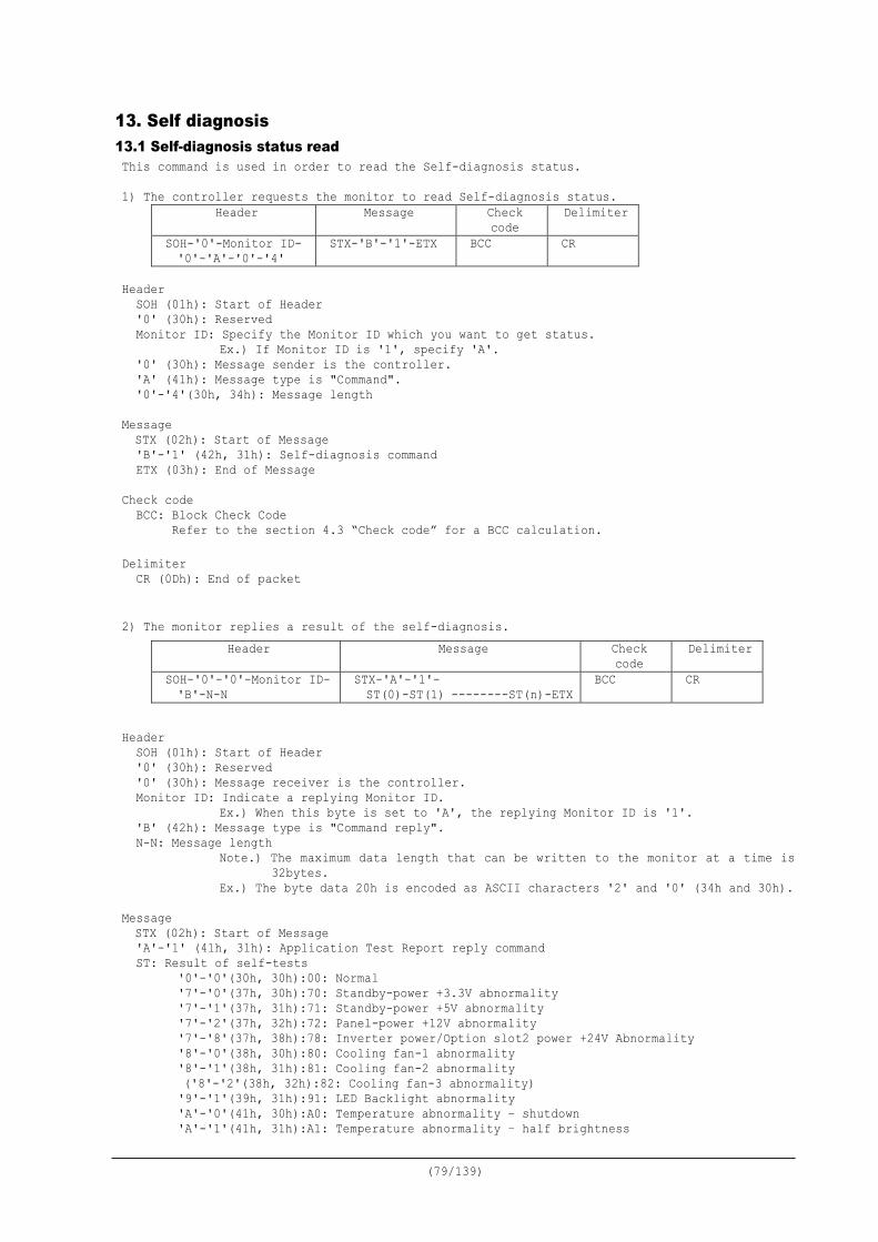
(79/139)
13. Self diagnosis 13.1 Self-diagnosis status read This command is used in order to read the Self-diagnosis status. 1) The controller requests the monitor to read Self-diagnosis status.
Header Message Check code
Delimiter
SOH-'0'-Monitor ID- '0'-'A'-'0'-'4'
STX-'B'-'1'-ETX BCC CR
Header
SOH (01h): Start of Header '0' (30h): Reserved Monitor ID: Specify the Monitor ID which you want to get status.
Ex.) If Monitor ID is '1', specify 'A'. '0' (30h): Message sender is the controller. 'A' (41h): Message type is "Command". '0'-'4'(30h, 34h): Message length
Message STX (02h): Start of Message 'B'-'1' (42h, 31h): Self-diagnosis command ETX (03h): End of Message
Check code
BCC: Block Check Code Refer to the section 4.3 “Check code” for a BCC calculation.
Delimiter
CR (0Dh): End of packet 2) The monitor replies a result of the self-diagnosis.
Header Message Check code
Delimiter
SOH-'0'-'0'-Monitor ID- 'B'-N-N
STX-'A'-'1'- ST(0)-ST(1) --------ST(n)-ETX
BCC CR
Header
SOH (01h): Start of Header '0' (30h): Reserved '0' (30h): Message receiver is the controller. Monitor ID: Indicate a replying Monitor ID.
Ex.) When this byte is set to 'A', the replying Monitor ID is '1'. 'B' (42h): Message type is "Command reply". N-N: Message length
Note.) The maximum data length that can be written to the monitor at a time is 32bytes.
Ex.) The byte data 20h is encoded as ASCII characters '2' and '0' (34h and 30h). Message STX (02h): Start of Message 'A'-'1' (41h, 31h): Application Test Report reply command ST: Result of self-tests
'0'-'0'(30h, 30h):00: Normal '7'-'0'(37h, 30h):70: Standby-power +3.3V abnormality '7'-'1'(37h, 31h):71: Standby-power +5V abnormality '7'-'2'(37h, 32h):72: Panel-power +12V abnormality '7'-'8'(37h, 38h):78: Inverter power/Option slot2 power +24V Abnormality '8'-'0'(38h, 30h):80: Cooling fan-1 abnormality '8'-'1'(38h, 31h):81: Cooling fan-2 abnormality ('8'-'2'(38h, 32h):82: Cooling fan-3 abnormality) '9'-'1'(39h, 31h):91: LED Backlight abnormality 'A'-'0'(41h, 30h):A0: Temperature abnormality – shutdown 'A'-'1'(41h, 31h):A1: Temperature abnormality – half brightness
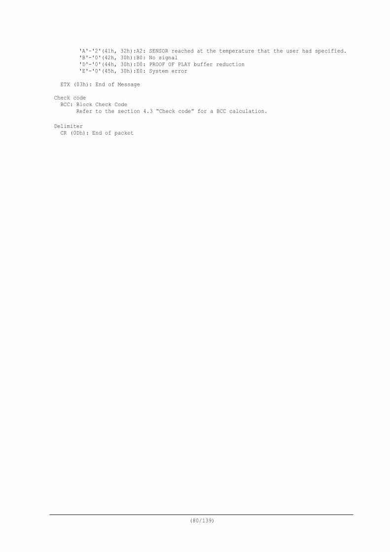
(80/139)
'A'-'2'(41h, 32h):A2: SENSOR reached at the temperature that the user had specified. 'B'-'0'(42h, 30h):B0: No signal 'D'-'0'(44h, 30h):D0: PROOF OF PLAY buffer reduction 'E'-'0'(45h, 30h):E0: System error
ETX (03h): End of Message
Check code
BCC: Block Check Code Refer to the section 4.3 “Check code” for a BCC calculation.
Delimiter
CR (0Dh): End of packet
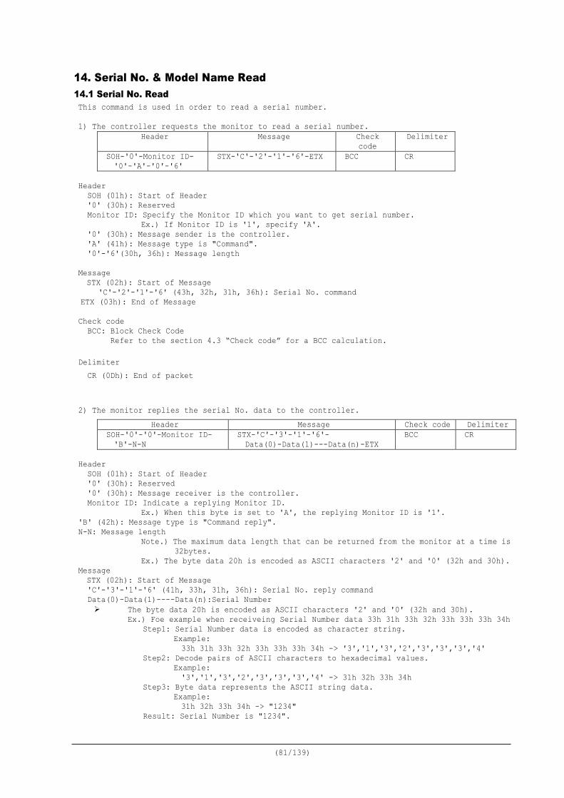
(81/139)
14. Serial No. & Model Name Read 14.1 Serial No. Read This command is used in order to read a serial number. 1) The controller requests the monitor to read a serial number.
Header Message Check code
Delimiter
SOH-'0'-Monitor ID- '0'-'A'-'0'-'6'
STX-'C'-'2'-'1'-'6'-ETX BCC CR
Header
SOH (01h): Start of Header '0' (30h): Reserved Monitor ID: Specify the Monitor ID which you want to get serial number.
Ex.) If Monitor ID is '1', specify 'A'. '0' (30h): Message sender is the controller. 'A' (41h): Message type is "Command". '0'-'6'(30h, 36h): Message length
Message STX (02h): Start of Message
'C'-'2'-'1'-'6' (43h, 32h, 31h, 36h): Serial No. command ETX (03h): End of Message Check code
BCC: Block Check Code Refer to the section 4.3 “Check code” for a BCC calculation.
Delimiter
CR (0Dh): End of packet 2) The monitor replies the serial No. data to the controller.
Header Message Check code Delimiter SOH-'0'-'0'-Monitor ID- 'B'-N-N
STX-'C'-'3'-'1'-'6'- Data(0)-Data(1)---Data(n)-ETX
BCC CR
Header
SOH (01h): Start of Header '0' (30h): Reserved '0' (30h): Message receiver is the controller. Monitor ID: Indicate a replying Monitor ID.
Ex.) When this byte is set to 'A', the replying Monitor ID is '1'. 'B' (42h): Message type is "Command reply". N-N: Message length
Note.) The maximum data length that can be returned from the monitor at a time is 32bytes.
Ex.) The byte data 20h is encoded as ASCII characters '2' and '0' (32h and 30h). Message STX (02h): Start of Message 'C'-'3'-'1'-'6' (41h, 33h, 31h, 36h): Serial No. reply command Data(0)-Data(1)----Data(n):Serial Number The byte data 20h is encoded as ASCII characters '2' and '0' (32h and 30h).
Ex.) Foe example when receiveing Serial Number data 33h 31h 33h 32h 33h 33h 33h 34h Step1: Serial Number data is encoded as character string.
Example: 33h 31h 33h 32h 33h 33h 33h 34h -> '3','1','3','2','3','3','3','4'
Step2: Decode pairs of ASCII characters to hexadecimal values. Example: '3','1','3','2','3','3','3','4' -> 31h 32h 33h 34h
Step3: Byte data represents the ASCII string data. Example: 31h 32h 33h 34h -> "1234"
Result: Serial Number is "1234".

(82/139)
Note: No null termination character is sent. ETX (03h): End of Message
Check code BCC: Block Check Code Refer to the section 4.3 “Check code” for a BCC calculation.
Delimiter
CR (0Dh): End of packet
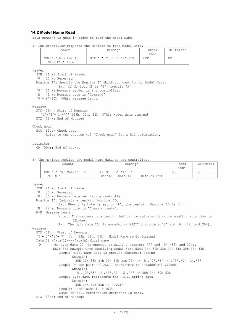
(83/139)
14.2 Model Name Read This command is used in order to read the Model Name. 1) The controller requests the monitor to read Model Name.
Header Message Check code
Delimiter
SOH-'0'-Monitor ID- '0'-'A'-'0'-'6'
STX-'C'-'2'-'1'-'7'-ETX BCC CR
Header
SOH (01h): Start of Header '0' (30h): Reserved Monitor ID: Specify the Monitor ID which you want to get Model Name.
Ex.) If Monitor ID is '1', specify 'A'. '0' (30h): Message sender is the controller. 'A' (41h): Message type is "Command". '0'-'6'(30h, 36h): Message length
Message STX (02h): Start of Message
'C'-'2'-'1'-'7' (43h, 32h, 31h, 37h): Model Name command ETX (03h): End of Message
Check code
BCC: Block Check Code Refer to the section 4.3 “Check code” for a BCC calculation.
Delimiter
CR (0Dh): End of packet 2) The monitor replies the model name data to the controller.
Header Message Check code
Delimiter
SOH-'0'-'0'-Monitor ID- 'B'-N-N
STX-'C'-'3'-'1'-'7'- Data(0) -Data(1)—----Data(n)-ETX
BCC CR
Header
SOH (01h): Start of Header '0' (30h): Reserved '0' (30h): Message receiver is the controller. Monitor ID: Indicate a replying Monitor ID.
Ex.) When this byte is set to 'A', the replying Monitor ID is '1'. 'B' (42h): Message type is "Command reply". N-N: Message length
Note.) The maximum data length that can be returned from the monitor at a time is 32bytes.
Ex.) The byte data 20h is encoded as ASCII characters '2' and '0' (32h and 30h). Message STX (02h): Start of Message 'C'-'3'-'1'-'7' (43h, 33h, 31h, 37h): Model Name reply Command Data(0) -Data(1)----Data(n):Model name The byte data 20h is encoded as ASCII characters '2' and '0' (32h and 30h).
Ex.) Foe example when receiving Model Name data 35h 30h 33h 34h 33h 30h 33h 33h Step1: Model Name data is encoded character string.
Example: 35h 30h 33h 34h 33h 30h 33h 33h -> '5','0','3','4','3','0','3','3'
Step2: Decode pairs of ASCII characters to hexadecimal values. Example: '5','0','3','4','3','0','3','3' -> 50h 34h 30h 33h
Step3: Byte data represents the ASCII string data. Example: 50h 34h 30h 33h -> "P403"
Result: Model Name is "P403". Note: No null termination character is sent.
ETX (03h): End of Message

(84/139)
Check code BCC: Block Check Code Refer to the section 4.3 “Check code” for a BCC calculation.
Delimiter
CR (0Dh): End of packet
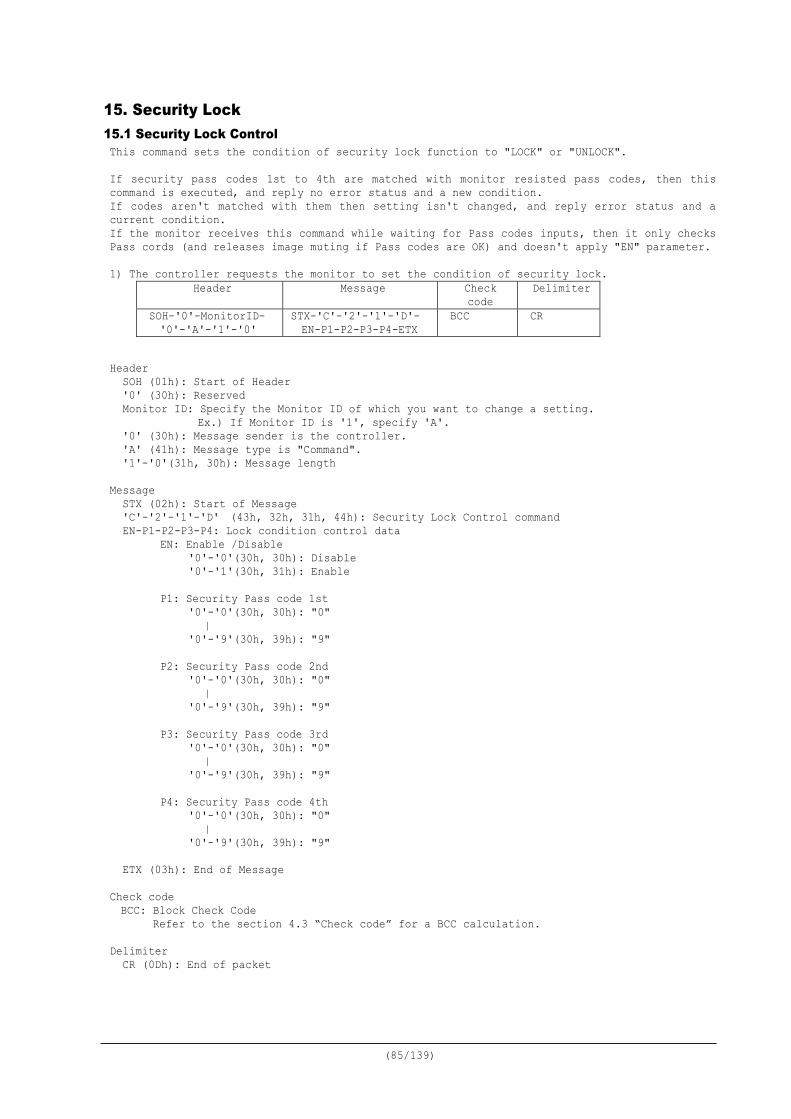
(85/139)
15. Security Lock 15.1 Security Lock Control This command sets the condition of security lock function to "LOCK" or "UNLOCK". If security pass codes 1st to 4th are matched with monitor resisted pass codes, then this command is executed, and reply no error status and a new condition. If codes aren't matched with them then setting isn't changed, and reply error status and a current condition. If the monitor receives this command while waiting for Pass codes inputs, then it only checks Pass cords (and releases image muting if Pass codes are OK) and doesn't apply "EN" parameter. 1) The controller requests the monitor to set the condition of security lock.
Header Message Check code
Delimiter
SOH-'0'-MonitorID- '0'-'A'-'1'-'0'
STX-'C'-'2'-'1'-'D'- EN-P1-P2-P3-P4-ETX
BCC CR
Header
SOH (01h): Start of Header '0' (30h): Reserved Monitor ID: Specify the Monitor ID of which you want to change a setting.
Ex.) If Monitor ID is '1', specify 'A'. '0' (30h): Message sender is the controller. 'A' (41h): Message type is "Command". '1'-'0'(31h, 30h): Message length
Message STX (02h): Start of Message 'C'-'2'-'1'-'D' (43h, 32h, 31h, 44h): Security Lock Control command EN-P1-P2-P3-P4: Lock condition control data
EN: Enable /Disable '0'-'0'(30h, 30h): Disable '0'-'1'(30h, 31h): Enable
P1: Security Pass code 1st '0'-'0'(30h, 30h): "0" | '0'-'9'(30h, 39h): "9"
P2: Security Pass code 2nd '0'-'0'(30h, 30h): "0" | '0'-'9'(30h, 39h): "9"
P3: Security Pass code 3rd '0'-'0'(30h, 30h): "0" | '0'-'9'(30h, 39h): "9"
P4: Security Pass code 4th '0'-'0'(30h, 30h): "0" | '0'-'9'(30h, 39h): "9"
ETX (03h): End of Message
Check code BCC: Block Check Code Refer to the section 4.3 “Check code” for a BCC calculation.
Delimiter
CR (0Dh): End of packet
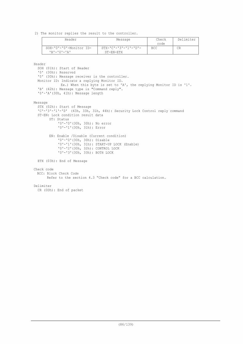
(86/139)
2) The monitor replies the result to the controller. Header Message Check
code Delimiter
SOH-'0'-'0'-Monitor ID- 'B'-'0'-'A'
STX-'C'-'3'-'1'-'D'- ST-EN-ETX
BCC CR
Header
SOH (01h): Start of Header '0' (30h): Reserved '0' (30h): Message receiver is the controller. Monitor ID: Indicate a replying Monitor ID.
Ex.) When this byte is set to 'A', the replying Monitor ID is '1'. 'B' (42h): Message type is "Command reply". '0'-'A'(30h, 41h): Message length
Message STX (02h): Start of Message 'C'-'3'-'1'-'D' (43h, 33h, 31h, 44h): Security Lock Control reply command ST-EN: Lock condition result data
ST: Status '0'-'0'(30h, 30h): No error '0'-'1'(30h, 31h): Error
EN: Enable /Disable (Current condition) '0'-'0'(30h, 30h): Disable '0'-'1'(30h, 31h): START-UP LOCK (Enable) '0'-'2'(30h, 32h): CONTROL LOCK '0'-'3'(30h, 33h): BOTH LOCK
ETX (03h): End of Message
Check code BCC: Block Check Code Refer to the section 4.3 “Check code” for a BCC calculation.
Delimiter
CR (0Dh): End of packet

(87/139)
16. Direct TV Chanel Read & Write When DTV unit (Option unit) is installed, channel settings is read and write directly.
16.1 Direct TV Chanel Read & Reply 1) The controller requests the monitor to read channel information.
Header Message Check code
Delimiter
SOH-'0'-Monitor ID- '0'-'A'-'0'-'6'
STX-'C'-'2'-'2'-'C'-ETX BCC CR
Header
SOH (01h): Start of Header '0' (30h): Reserved Monitor ID: Specify the Monitor ID which you want to get Model Name.
Ex.) If Monitor ID is '1', specify 'A'. '0' (30h): Message sender is the controller. 'A' (41h): Message type is "Command". '0'-'6'(30h, 36h): Message length
Message STX (02h): Start of Message
'C'-'2'-'2'-'C' (43h, 32h, 32h, 43h): Direct TV Channel Read command ETX (03h): End of Message
Check code
BCC: Block Check Code Refer to the section 4.3 “Check code” for a BCC calculation.
Delimiter CR (0Dh): End of packet 2) The monitor replies the result to the controller.
Header Message Check code Delimiter SOH-'0'-'0'-Monitor ID- 'B'-'1'-'2'
STX-'C'-'3'-'2'-'C'- MajorCH-MinorCH-ETX
BCC CR
Header
SOH (01h): Start of Header '0' (30h): Reserved '0' (30h): Message receiver is the controller. Monitor ID: Indicate a replying Monitor ID.
Ex.) When this byte is set to 'A', the replying Monitor ID is '1'. 'B' (42h): Message type is "Command reply". '1'-'2'(31h, 32h): Message length = 18bytes
Message STX (02h): Start of Message 'C'-'3'-'2'-'C' (43h, 33h, 32h, 43h): Direct TV Channel read reply command MajorCH: Major Channel (00000000h – FFFFFFFFh),
'0'-'0'-'0'-'0'-'0'-'0'-'0'-'0' - 'F'-'F'-'F'-'F'-'F'-'F'-'F'-'F' MinorCH: Minor Channel (0000h – FFFFh),
'0'-'0'-'0'-'0' - 'F'-'F'-'F'-'F' ETX (03h): End of Message
Check code BCC: Block Check Code Refer to the section 4.3 “Check code” for a BCC calculation.
Delimiter
CR (0Dh): End of packet
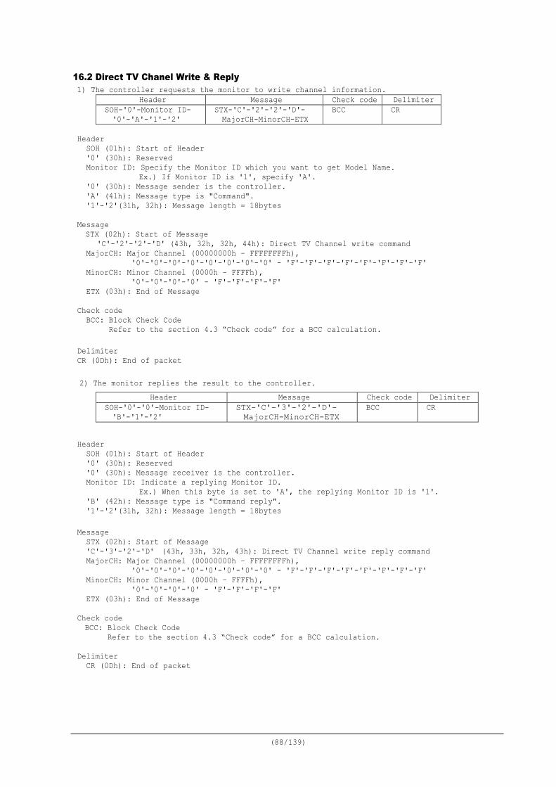
(88/139)
16.2 Direct TV Chanel Write & Reply 1) The controller requests the monitor to write channel information.
Header Message Check code Delimiter SOH-'0'-Monitor ID- '0'-'A'-'1'-'2'
STX-'C'-'2'-'2'-'D'- MajorCH-MinorCH-ETX
BCC CR
Header
SOH (01h): Start of Header '0' (30h): Reserved Monitor ID: Specify the Monitor ID which you want to get Model Name.
Ex.) If Monitor ID is '1', specify 'A'. '0' (30h): Message sender is the controller. 'A' (41h): Message type is "Command". '1'-'2'(31h, 32h): Message length = 18bytes
Message STX (02h): Start of Message
'C'-'2'-'2'-'D' (43h, 32h, 32h, 44h): Direct TV Channel write command MajorCH: Major Channel (00000000h – FFFFFFFFh),
'0'-'0'-'0'-'0'-'0'-'0'-'0'-'0' - 'F'-'F'-'F'-'F'-'F'-'F'-'F'-'F' MinorCH: Minor Channel (0000h – FFFFh),
'0'-'0'-'0'-'0' - 'F'-'F'-'F'-'F' ETX (03h): End of Message
Check code
BCC: Block Check Code Refer to the section 4.3 “Check code” for a BCC calculation.
Delimiter CR (0Dh): End of packet 2) The monitor replies the result to the controller.
Header Message Check code Delimiter SOH-'0'-'0'-Monitor ID- 'B'-'1'-'2'
STX-'C'-'3'-'2'-'D'- MajorCH-MinorCH-ETX
BCC CR
Header
SOH (01h): Start of Header '0' (30h): Reserved '0' (30h): Message receiver is the controller. Monitor ID: Indicate a replying Monitor ID.
Ex.) When this byte is set to 'A', the replying Monitor ID is '1'. 'B' (42h): Message type is "Command reply". '1'-'2'(31h, 32h): Message length = 18bytes
Message STX (02h): Start of Message 'C'-'3'-'2'-'D' (43h, 33h, 32h, 43h): Direct TV Channel write reply command MajorCH: Major Channel (00000000h – FFFFFFFFh),
'0'-'0'-'0'-'0'-'0'-'0'-'0'-'0' - 'F'-'F'-'F'-'F'-'F'-'F'-'F'-'F' MinorCH: Minor Channel (0000h – FFFFh),
'0'-'0'-'0'-'0' - 'F'-'F'-'F'-'F' ETX (03h): End of Message
Check code BCC: Block Check Code Refer to the section 4.3 “Check code” for a BCC calculation.
Delimiter
CR (0Dh): End of packet
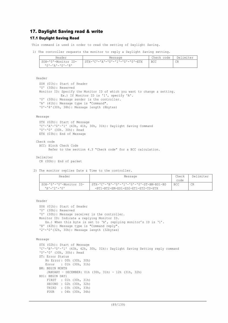
(89/139)
17. Daylight Saving read & write 17.1 Daylight Saving Read This command is used in order to read the setting of Daylight Saving. 1) The controller requests the monitor to reply a Daylight Saving setting.
Header Message Check code Delimiter SOH-'0'-Monitor ID- '0'-'A'-'0'-'8'
STX-'C'-'A'-'0'-'1'-'0'-'0'-ETX BCC CR
Header SOH (01h): Start of Header '0' (30h): Reserved Monitor ID: Specify the Monitor ID of which you want to change a setting.
Ex.) If Monitor ID is '1', specify 'A'. '0' (30h): Message sender is the controller. 'A' (41h): Message type is "Command". '0'-'8'(30h, 38h): Message length (8bytes)
Message STX (02h): Start of Message 'C'-'A'-'0'-'1' (43h, 41h, 30h, 31h): Daylight Saving Command '0'-'0' (30h. 30h): Read ETX (03h): End of Message
Check code BCC: Block Check Code Refer to the section 4.3 “Check code” for a BCC calculation.
Delimiter CR (0Dh): End of packet
2) The monitor replies Date & Time to the controller.
Header Message Check code
Delimiter
SOH-'0'-'0'-Monitor ID- 'B'-'2'-'0'
STX-'C'-'B'-'0'-'1'-'0'-'0'-ST-BM-BD1-BD -BT1-BT2-EM-ED1-ED2-ET1-ET2-TD-ETX
BCC CR
Header SOH (01h): Start of Header '0' (30h): Reserved '0' (30h): Message receiver is the controller. Monitor ID: Indicate a replying Monitor ID.
Ex.) When this byte is set to ‘A’, replying monitor’s ID is ‘1’. 'B' (42h): Message type is "Command reply". '2'-'0'(32h, 30h): Message length (32bytes)
Message STX (02h): Start of Message 'C'-'B'-'0'-'1' (43h, 42h, 30h, 31h): Daylight Saving Setting reply command '0'-'0' (30h, 30h): Read ST: Error Status No Error : 00h (30h, 30h) Error : 01h (30h, 31h) BM: BEGIN MONTH JANUARY – DECEMBER: 01h (30h, 31h) - 12h (31h, 32h) BD1: BEGIN DAY1 FIRST : 01h (30h, 31h) SECOND : 02h (30h, 32h) THIRD : 03h (30h, 33h) FOUR : 04h (30h, 34h)
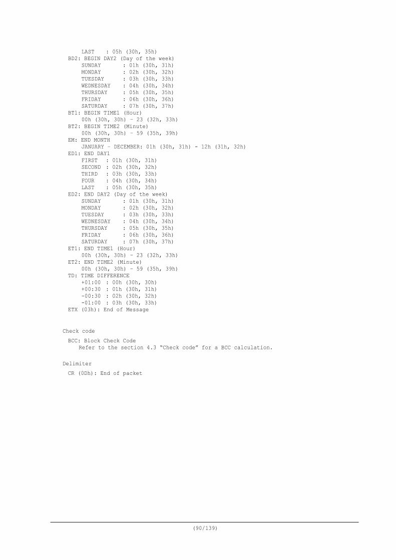
(90/139)
LAST : 05h (30h, 35h) BD2: BEGIN DAY2 (Day of the week) SUNDAY : 01h (30h, 31h) MONDAY : 02h (30h, 32h) TUESDAY : 03h (30h, 33h) WEDNESDAY : 04h (30h, 34h) THURSDAY : 05h (30h, 35h) FRIDAY : 06h (30h, 36h) SATURDAY : 07h (30h, 37h) BT1: BEGIN TIME1 (Hour) 00h (30h, 30h) – 23 (32h, 33h) BT2: BEGIN TIME2 (Minute) 00h (30h, 30h) – 59 (35h, 39h) EM: END MONTH JANUARY – DECEMBER: 01h (30h, 31h) - 12h (31h, 32h) ED1: END DAY1 FIRST : 01h (30h, 31h) SECOND : 02h (30h, 32h) THIRD : 03h (30h, 33h) FOUR : 04h (30h, 34h) LAST : 05h (30h, 35h) ED2: END DAY2 (Day of the week) SUNDAY : 01h (30h, 31h) MONDAY : 02h (30h, 32h) TUESDAY : 03h (30h, 33h) WEDNESDAY : 04h (30h, 34h) THURSDAY : 05h (30h, 35h) FRIDAY : 06h (30h, 36h) SATURDAY : 07h (30h, 37h) ET1: END TIME1 (Hour) 00h (30h, 30h) – 23 (32h, 33h) ET2: END TIME2 (Minute) 00h (30h, 30h) – 59 (35h, 39h) TD: TIME DIFFERENCE +01:00 : 00h (30h, 30h) +00:30 : 01h (30h, 31h) -00:30 : 02h (30h, 32h) -01:00 : 03h (30h, 33h) ETX (03h): End of Message
Check code BCC: Block Check Code
Refer to the section 4.3 “Check code” for a BCC calculation. Delimiter CR (0Dh): End of packet
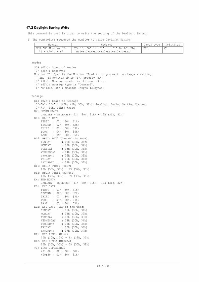
(91/139)
17.2 Daylight Saving Write This command is used in order to write the setting of the Daylight Saving. 1) The controller requests the monitor to write Daylight Saving.
Header Message Check code Delimiter SOH-'0'-Monitor ID- '0'-'A'-'1'-'E'
STX-'C'-'A'-'0'-'1'-'0'-'1'-BM-BD1-BD2- BT1-BT2-EM-ED1-ED2-ET1-ET2-TD-ETX
BCC CR
Header SOH (01h): Start of Header '0' (30h): Reserved Monitor ID: Specify the Monitor ID of which you want to change a setting.
Ex.) If Monitor ID is '1', specify 'A'. '0' (30h): Message sender is the controller. 'A' (41h): Message type is "Command". '1'-'E'(31h, 45h): Message length (30bytes)
Message STX (02h): Start of Message 'C'-'A'-'0'-'1' (43h, 41h, 30h, 31h): Daylight Saving Setting Command '0'-'1' (30h, 31h): Write BM: BEGIN MONTH JANUARY – DECEMBER: 01h (30h, 31h) - 12h (31h, 32h) BD1: BEGIN DAY1 FIRST : 01h (30h, 31h) SECOND : 02h (30h, 32h) THIRD : 03h (30h, 33h) FOUR : 04h (30h, 34h) LAST : 05h (30h, 35h) BD2: BEGIN DAY2 (Day of the week) SUNDAY : 01h (30h, 31h) MONDAY : 02h (30h, 32h) TUESDAY : 03h (30h, 33h) WEDNESDAY : 04h (30h, 34h) THURSDAY : 05h (30h, 35h) FRIDAY : 06h (30h, 36h) SATURDAY : 07h (30h, 37h) BT1: BEGIN TIME1 (Hour) 00h (30h, 30h) – 23 (32h, 33h) BT2: BEGIN TIME2 (Minute) 00h (30h, 30h) – 59 (35h, 39h) EM: END MONTH JANUARY – DECEMBER: 01h (30h, 31h) - 12h (31h, 32h) ED1: END DAY1 FIRST : 01h (30h, 31h) SECOND : 02h (30h, 32h) THIRD : 03h (30h, 33h) FOUR : 04h (30h, 34h) LAST : 05h (30h, 35h) ED2: END DAY2 (Day of the week) SUNDAY : 01h (30h, 31h) MONDAY : 02h (30h, 32h) TUESDAY : 03h (30h, 33h) WEDNESDAY : 04h (30h, 34h) THURSDAY : 05h (30h, 35h) FRIDAY : 06h (30h, 36h) SATURDAY : 07h (30h, 37h) ET1: END TIME1 (Hour) 00h (30h, 30h) – 23 (32h, 33h) ET2: END TIME2 (Minute) 00h (30h, 30h) – 59 (35h, 39h) TD: TIME DIFFERENCE +01:00 : 00h (30h, 30h) +00:30 : 01h (30h, 31h)
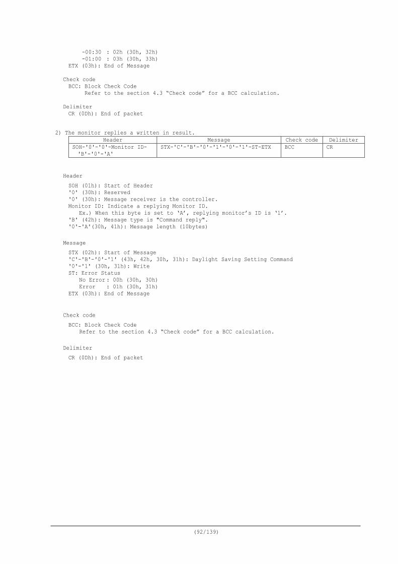
(92/139)
-00:30 : 02h (30h, 32h) -01:00 : 03h (30h, 33h) ETX (03h): End of Message
Check code BCC: Block Check Code Refer to the section 4.3 “Check code” for a BCC calculation.
Delimiter CR (0Dh): End of packet
2) The monitor replies a written in result.
Header Message Check code Delimiter SOH-'0'-'0'-Monitor ID- 'B'-'0'-'A'
STX-'C'-'B'-'0'-'1'-'0'-'1'-ST-ETX BCC CR
Header SOH (01h): Start of Header '0' (30h): Reserved '0' (30h): Message receiver is the controller. Monitor ID: Indicate a replying Monitor ID.
Ex.) When this byte is set to ‘A’, replying monitor’s ID is ‘1’. 'B' (42h): Message type is "Command reply". '0'-'A'(30h, 41h): Message length (10bytes)
Message STX (02h): Start of Message 'C'-'B'-'0'-'1' (43h, 42h, 30h, 31h): Daylight Saving Setting Command '0'-'1' (30h, 31h): Write ST: Error Status No Error : 00h (30h, 30h) Error : 01h (30h, 31h) ETX (03h): End of Message
Check code BCC: Block Check Code
Refer to the section 4.3 “Check code” for a BCC calculation. Delimiter CR (0Dh): End of packet
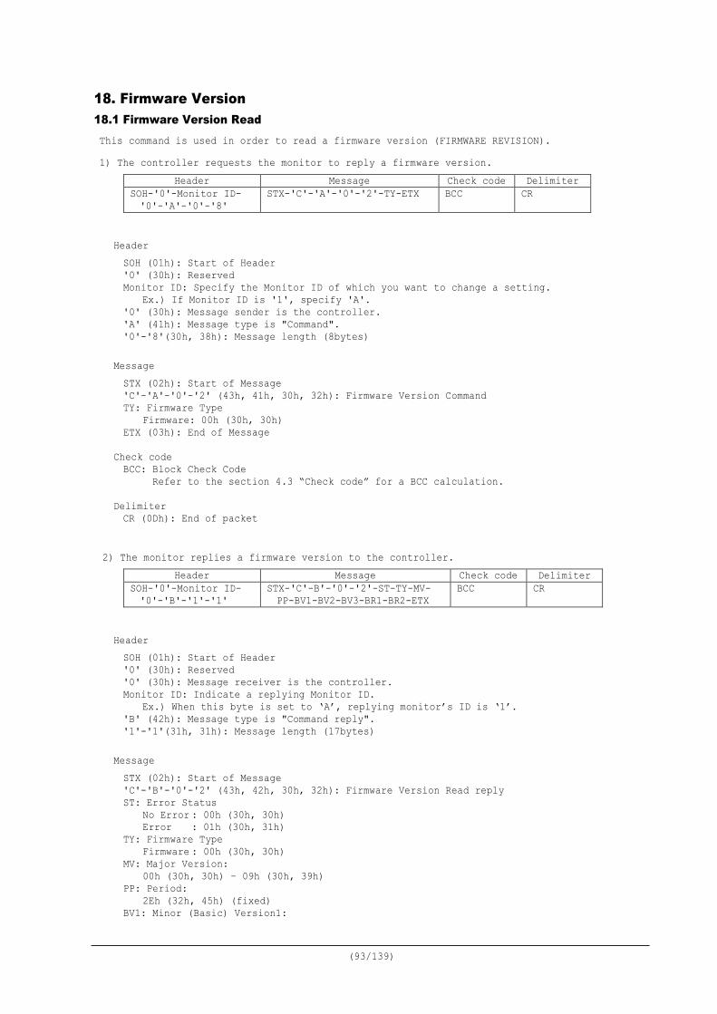
(93/139)
18. Firmware Version 18.1 Firmware Version Read This command is used in order to read a firmware version (FIRMWARE REVISION). 1) The controller requests the monitor to reply a firmware version.
Header Message Check code Delimiter SOH-'0'-Monitor ID- '0'-'A'-'0'-'8'
STX-'C'-'A'-'0'-'2'-TY-ETX BCC CR
Header SOH (01h): Start of Header '0' (30h): Reserved Monitor ID: Specify the Monitor ID of which you want to change a setting.
Ex.) If Monitor ID is '1', specify 'A'. '0' (30h): Message sender is the controller. 'A' (41h): Message type is "Command". '0'-'8'(30h, 38h): Message length (8bytes)
Message STX (02h): Start of Message 'C'-'A'-'0'-'2' (43h, 41h, 30h, 32h): Firmware Version Command TY: Firmware Type Firmware: 00h (30h, 30h) ETX (03h): End of Message
Check code BCC: Block Check Code Refer to the section 4.3 “Check code” for a BCC calculation.
Delimiter CR (0Dh): End of packet
2) The monitor replies a firmware version to the controller.
Header Message Check code Delimiter SOH-'0'-Monitor ID- '0'-'B'-'1'-'1'
STX-'C'-B'-'0'-'2'-ST-TY-MV- PP-BV1-BV2-BV3-BR1-BR2-ETX
BCC CR
Header SOH (01h): Start of Header '0' (30h): Reserved '0' (30h): Message receiver is the controller. Monitor ID: Indicate a replying Monitor ID.
Ex.) When this byte is set to ‘A’, replying monitor’s ID is ‘1’. 'B' (42h): Message type is "Command reply". '1'-'1'(31h, 31h): Message length (17bytes)
Message STX (02h): Start of Message 'C'-'B'-'0'-'2' (43h, 42h, 30h, 32h): Firmware Version Read reply ST: Error Status No Error : 00h (30h, 30h) Error : 01h (30h, 31h) TY: Firmware Type Firmware : 00h (30h, 30h) MV: Major Version:
00h (30h, 30h) – 09h (30h, 39h) PP: Period:
2Eh (32h, 45h) (fixed) BV1: Minor (Basic) Version1:
(94/139)
00h (30h, 30h) – 09h (30h, 39h) BV2: Minor (Basic) Version2:
00h (30h, 30h) – 09h (30h, 39h) BV3: Minor (Basic) Version3:
00h (30h, 30h) – 09h (30h, 39h) BR1: Branch Version1:
A:41h (34h, 31h) – Z:5Ah (35h, 41h) BR2: Branch Version2:
A:41h (34h, 31h) – Z:5Ah (35h, 41h)
Check code BCC: Block Check Code
Refer to the section 4.3 “Check code” for a BCC calculation. Delimiter CR (0Dh): End of packet
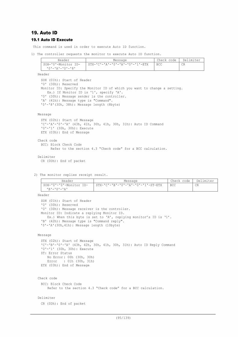
(95/139)
19. Auto ID 19.1 Auto ID Execute This command is used in order to execute Auto ID function. 1) The controller requests the monitor to execute Auto ID function.
Header Message Check code Delimiter SOH-'0'-Monitor ID- '0'-'A'-'0'-'8'
STX-'C'-'A'-'0'-'A'-'0'-'1'-ETX BCC CR
Header SOH (01h): Start of Header '0' (30h): Reserved Monitor ID: Specify the Monitor ID of which you want to change a setting.
Ex.) If Monitor ID is '1', specify 'A'. '0' (30h): Message sender is the controller. 'A' (41h): Message type is "Command". '0'-'8'(30h, 38h): Message length (8byte)
Message STX (02h): Start of Message 'C'-'A'-'0'-'A' (43h, 41h, 30h, 41h, 30h, 31h): Auto ID Command '0'-'1' (30h, 30h): Execute ETX (03h): End of Message
Check code BCC: Block Check Code Refer to the section 4.3 “Check code” for a BCC calculation.
Delimiter CR (0Dh): End of packet
2) The monitor replies receipt result. Header Message Check code Delimiter
SOH-'0'-'0'-Monitor ID- 'B'-'0'-'A'
STX-'C'-'B'-'0'-'A'-'0'-'1'-ST-ETX BCC CR
Header SOH (01h): Start of Header '0' (30h): Reserved '0' (30h): Message receiver is the controller. Monitor ID: Indicate a replying Monitor ID.
Ex.) When this byte is set to ‘A’, replying monitor’s ID is ‘1’. 'B' (42h): Message type is "Command reply". '0'-'A'(30h,41h): Message length (10byte)
Message STX (02h): Start of Message 'C'-'B'-'0'-'A' (43h, 42h, 30h, 41h, 30h, 31h): Auto ID Reply Command '0'-'1' (30h, 30h): Execute ST: Error Status No Error : 00h (30h, 30h) Error : 01h (30h, 31h) ETX (03h): End of Message
Check code BCC: Block Check Code
Refer to the section 4.3 “Check code” for a BCC calculation. Delimiter CR (0Dh): End of packet
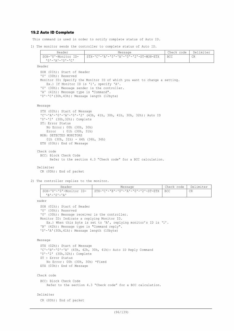
(96/139)
19.2 Auto ID Complete This command is used in order to notify complete status of Auto ID. 1) The monitor sends the controller to complete status of Auto ID.
Header Message Check code Delimiter SOH-'0'-Monitor ID- '0'-'A'-'0'-'C'
STX-'C'-'A'-'0'-'A'-'0'-'2'-ST-MON-ETX BCC CR
Header SOH (01h): Start of Header '0' (30h): Reserved Monitor ID: Specify the Monitor ID of which you want to change a setting.
Ex.) If Monitor ID is '1', specify 'A'. '0' (30h): Message sender is the controller. 'A' (41h): Message type is "Command". '0'-'C'(30h,43h): Message length (12byte)
Message STX (02h): Start of Message 'C'-'A'-'0'-'A'-'0'-'2' (43h, 41h, 30h, 41h, 30h, 32h): Auto ID '0'-'2' (30h,32h): Complete ST: Error Status No Error : 00h (30h, 30h) Error : 01h (30h, 31h) MON: DETECTED MONITORS 01h (30h, 31h) - 64h (36h, 34h) ETX (03h): End of Message
Check code BCC: Block Check Code Refer to the section 4.3 “Check code” for a BCC calculation.
Delimiter CR (0Dh): End of packet
2) The controller replies to the monitor. Header Message Check code Delimiter
SOH-'0'-'0'-Monitor ID- 'B'-'0'-'A'
STX-'C'-'B'-'0'-'A'-'0'-'2'-ST-ETX BCC CR
eader SOH (01h): Start of Header '0' (30h): Reserved '0' (30h): Message receiver is the controller. Monitor ID: Indicate a replying Monitor ID.
Ex.) When this byte is set to ‘A’, replying monitor’s ID is ‘1’. 'B' (42h): Message type is "Command reply". '0'-'A'(30h,41h): Message length (10byte)
Message STX (02h): Start of Message 'C'-'B'-'0'-'A' (43h, 42h, 30h, 41h): Auto ID Reply Command '0'-'2' (30h,32h): Complete ST : Error Status No Error : 00h (30h, 30h) *Fixed ETX (03h): End of Message
Check code BCC: Block Check Code
Refer to the section 4.3 “Check code” for a BCC calculation. Delimiter CR (0Dh): End of packet
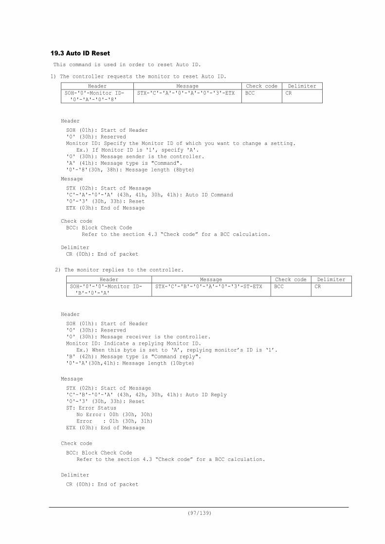
(97/139)
19.3 Auto ID Reset This command is used in order to reset Auto ID. 1) The controller requests the monitor to reset Auto ID.
Header Message Check code Delimiter SOH-'0'-Monitor ID- '0'-'A'-'0'-'8'
STX-'C'-'A'-'0'-'A'-'0'-'3'-ETX BCC CR
Header SOH (01h): Start of Header '0' (30h): Reserved Monitor ID: Specify the Monitor ID of which you want to change a setting.
Ex.) If Monitor ID is '1', specify 'A'. '0' (30h): Message sender is the controller. 'A' (41h): Message type is "Command". '0'-'8'(30h, 38h): Message length (8byte)
Message STX (02h): Start of Message 'C'-'A'-'0'-'A' (43h, 41h, 30h, 41h): Auto ID Command '0'-'3' (30h, 33h): Reset ETX (03h): End of Message
Check code BCC: Block Check Code Refer to the section 4.3 “Check code” for a BCC calculation.
Delimiter CR (0Dh): End of packet
2) The monitor replies to the controller.
Header Message Check code Delimiter SOH-'0'-'0'-Monitor ID- 'B'-'0'-'A'
STX-'C'-'B'-'0'-'A'-'0'-'3'-ST-ETX BCC CR
Header SOH (01h): Start of Header '0' (30h): Reserved '0' (30h): Message receiver is the controller. Monitor ID: Indicate a replying Monitor ID.
Ex.) When this byte is set to ‘A’, replying monitor’s ID is ‘1’. 'B' (42h): Message type is "Command reply". '0'-'A'(30h,41h): Message length (10byte)
Message STX (02h): Start of Message 'C'-'B'-'0'-'A' (43h, 42h, 30h, 41h): Auto ID Reply '0'-'3' (30h, 33h): Reset ST: Error Status No Error : 00h (30h, 30h) Error : 01h (30h, 31h) ETX (03h): End of Message
Check code BCC: Block Check Code
Refer to the section 4.3 “Check code” for a BCC calculation.
Delimiter CR (0Dh): End of packet
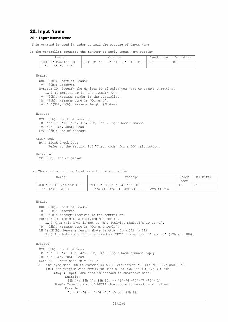
(98/139)
20. Input Name 20.1 Input Name Read This command is used in order to read the setting of Input Name. 1) The controller requests the monitor to reply Input Name setting.
Header Message Check code Delimiter SOH-'0'-Monitor ID- '0'-'A'-'0'-'8'
STX-'C'-'A'-'0'-'4'-'0'-'0'-ETX BCC CR
Header SOH (01h): Start of Header '0' (30h): Reserved Monitor ID: Specify the Monitor ID of which you want to change a setting.
Ex.) If Monitor ID is '1', specify 'A'. '0' (30h): Message sender is the controller. 'A' (41h): Message type is "Command". '0'-'8'(30h, 38h): Message length (8bytes)
Message STX (02h): Start of Message 'C'-'A'-'0'-'4' (43h, 41h, 30h, 34h): Input Name Command '0'-'0' (30h. 30h): Read ETX (03h): End of Message
Check code BCC: Block Check Code Refer to the section 4.3 “Check code” for a BCC calculation.
Delimiter CR (0Dh): End of packet
2) The monitor replies Input Name to the controller. Header Message Check
code Delimiter
SOH-'0'-'0'-Monitor ID- 'B'-LN(H)-LN(L)
STX-'C'-'B'-'0'-'4'-'0'-'0'- Data(0)-Data(1)-Data(2)- --- -Data(n)-ETX
BCC CR
Header SOH (01h): Start of Header '0' (30h): Reserved '0' (30h): Message receiver is the controller. Monitor ID: Indicate a replying Monitor ID.
Ex.) When this byte is set to ‘A’, replying monitor’s ID is ‘1’. 'B' (42h): Message type is "Command reply". LN(H)-LN(L): Message length (byte length), from STX to ETX
Ex.) The byte data 20h is encoded as ASCII characters '2' and '0' (32h and 30h).
Message STX (02h): Start of Message 'C'-'B'-'0'-'4' (43h, 42h, 30h, 34h): Input Name command reply '0'-'0' (30h, 30h): Read Data(n) : Input name *n = Max 14 The byte data 20h is encoded as ASCII characters '2' and '0' (32h and 30h).
Ex.) For example when receiving Data(n) of 35h 36h 34h 37h 34h 31h Step1: Input Name data is encoded as character code.
Example: 35h 36h 34h 37h 34h 31h -> '5'-'6'-'4'-'7'-'4'-'1'
Step2: Decode pairs of ASCII characters to hexadecimal values. Example: '5'-'6'-'4'-'7'-'4'-'1' -> 56h 47h 41h

(99/139)
Step3: Byte data represents the ASCII string data. Example: 56h 47h 41h -> “VGA”
Result: Input Name is “VGA”. Note: No null termination character is sent.
ETX (03h): End of Message
Check code BCC: Block Check Code
Refer to the section 4.3 “Check code” for a BCC calculation. Delimiter CR (0Dh): End of packet
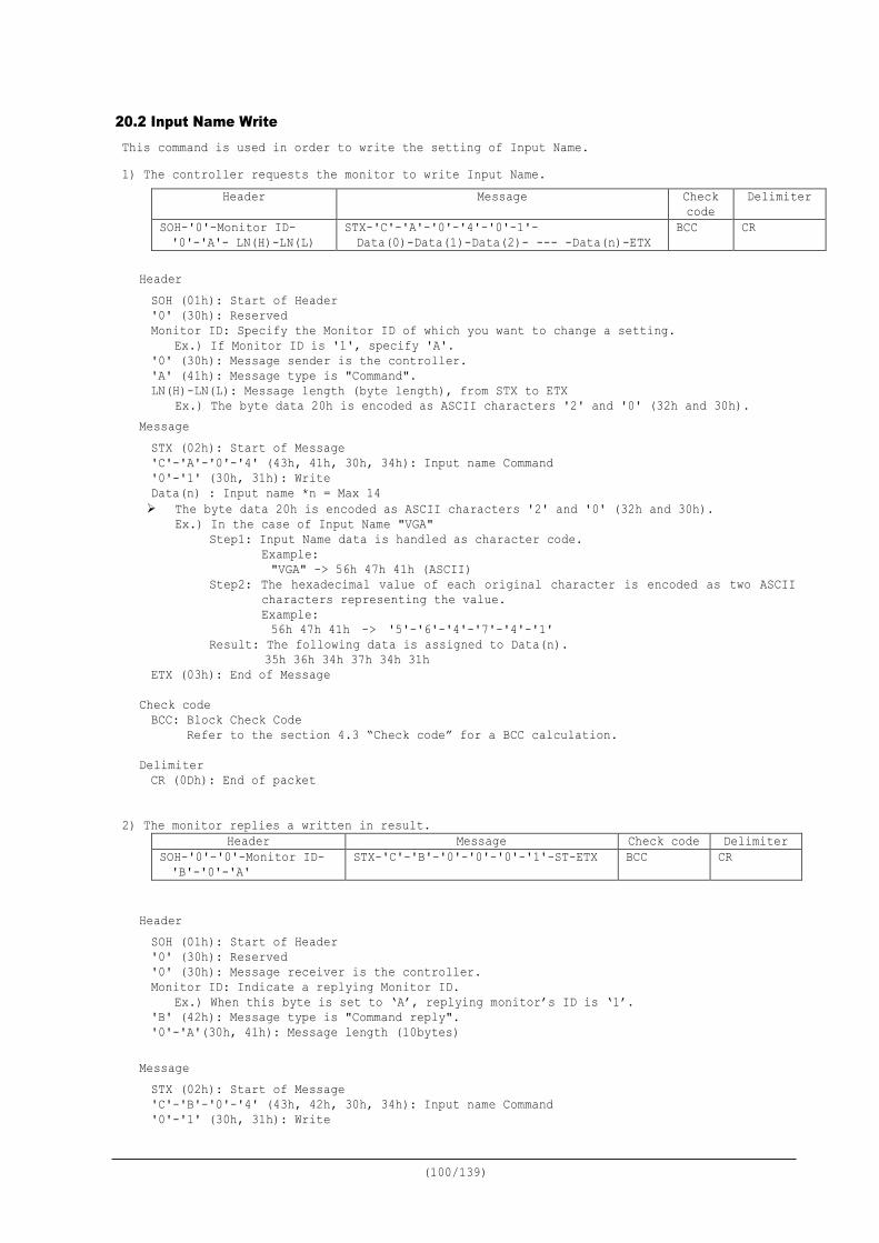
(100/139)
20.2 Input Name Write This command is used in order to write the setting of Input Name. 1) The controller requests the monitor to write Input Name.
Header Message Check code
Delimiter
SOH-'0'-Monitor ID- '0'-'A'- LN(H)-LN(L)
STX-'C'-'A'-'0'-'4'-'0'-1'- Data(0)-Data(1)-Data(2)- --- -Data(n)-ETX
BCC CR
Header SOH (01h): Start of Header '0' (30h): Reserved Monitor ID: Specify the Monitor ID of which you want to change a setting.
Ex.) If Monitor ID is '1', specify 'A'. '0' (30h): Message sender is the controller. 'A' (41h): Message type is "Command". LN(H)-LN(L): Message length (byte length), from STX to ETX
Ex.) The byte data 20h is encoded as ASCII characters '2' and '0' (32h and 30h). Message STX (02h): Start of Message 'C'-'A'-'0'-'4' (43h, 41h, 30h, 34h): Input name Command '0'-'1' (30h, 31h): Write Data(n) : Input name *n = Max 14 The byte data 20h is encoded as ASCII characters '2' and '0' (32h and 30h).
Ex.) In the case of Input Name "VGA" Step1: Input Name data is handled as character code.
Example: "VGA" -> 56h 47h 41h (ASCII)
Step2: The hexadecimal value of each original character is encoded as two ASCII characters representing the value. Example: 56h 47h 41h -> '5'-'6'-'4'-'7'-'4'-'1'
Result: The following data is assigned to Data(n). 35h 36h 34h 37h 34h 31h
ETX (03h): End of Message
Check code BCC: Block Check Code Refer to the section 4.3 “Check code” for a BCC calculation.
Delimiter CR (0Dh): End of packet
2) The monitor replies a written in result. Header Message Check code Delimiter
SOH-'0'-'0'-Monitor ID- 'B'-'0'-'A'
STX-'C'-'B'-'0'-'0'-'0'-'1'-ST-ETX BCC CR
Header SOH (01h): Start of Header '0' (30h): Reserved '0' (30h): Message receiver is the controller. Monitor ID: Indicate a replying Monitor ID.
Ex.) When this byte is set to ‘A’, replying monitor’s ID is ‘1’. 'B' (42h): Message type is "Command reply". '0'-'A'(30h, 41h): Message length (10bytes)
Message STX (02h): Start of Message 'C'-'B'-'0'-'4' (43h, 42h, 30h, 34h): Input name Command '0'-'1' (30h, 31h): Write

(101/139)
ST: Status 00h (30h, 30h): No Error 01h (30h, 31h): Error ETX (03h): End of Message
Check code BCC: Block Check Code
Refer to the section 4.3 “Check code” for a BCC calculation. Delimiter CR (0Dh): End of packet
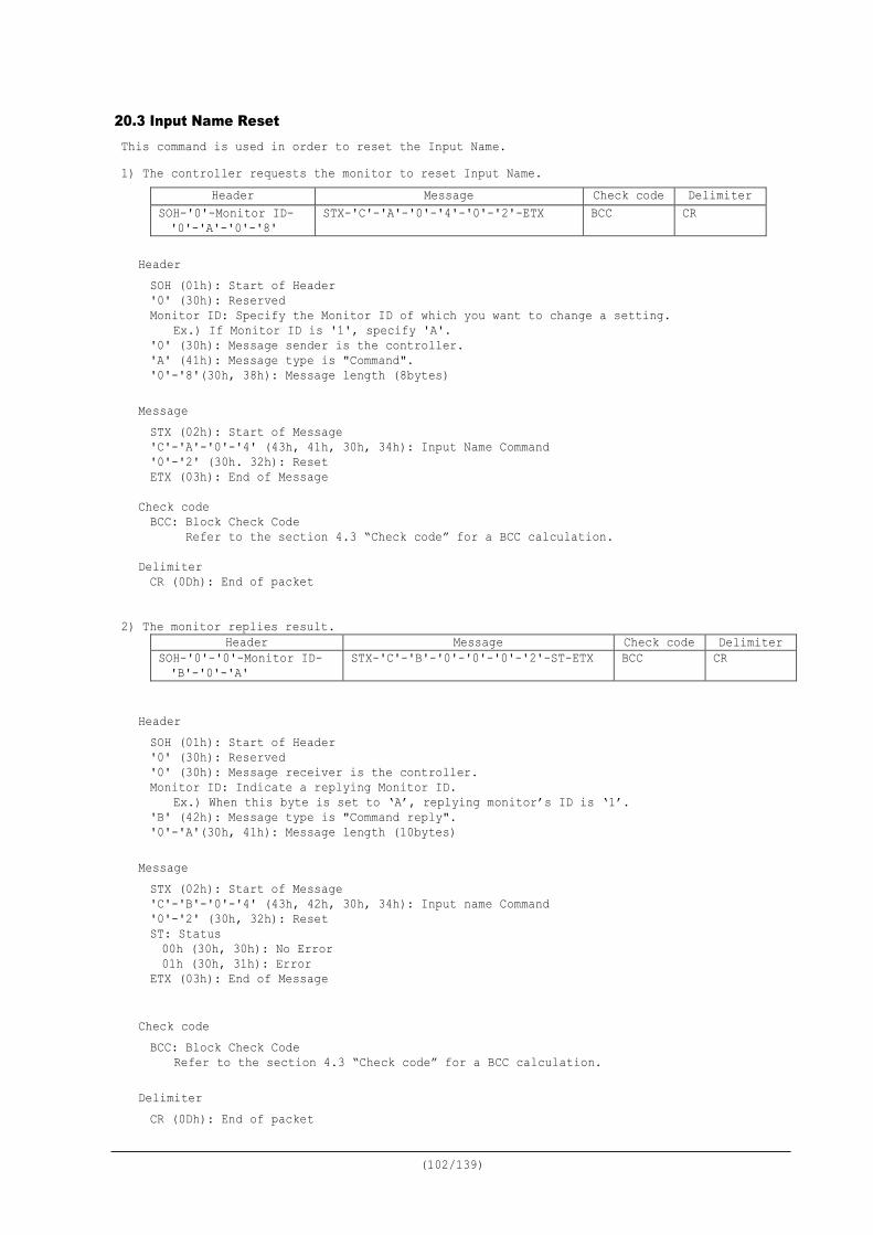
(102/139)
20.3 Input Name Reset This command is used in order to reset the Input Name. 1) The controller requests the monitor to reset Input Name.
Header Message Check code Delimiter SOH-'0'-Monitor ID- '0'-'A'-'0'-'8'
STX-'C'-'A'-'0'-'4'-'0'-'2'-ETX BCC CR
Header SOH (01h): Start of Header '0' (30h): Reserved Monitor ID: Specify the Monitor ID of which you want to change a setting.
Ex.) If Monitor ID is '1', specify 'A'. '0' (30h): Message sender is the controller. 'A' (41h): Message type is "Command". '0'-'8'(30h, 38h): Message length (8bytes)
Message STX (02h): Start of Message 'C'-'A'-'0'-'4' (43h, 41h, 30h, 34h): Input Name Command '0'-'2' (30h. 32h): Reset ETX (03h): End of Message
Check code BCC: Block Check Code Refer to the section 4.3 “Check code” for a BCC calculation.
Delimiter CR (0Dh): End of packet
2) The monitor replies result.
Header Message Check code Delimiter SOH-'0'-'0'-Monitor ID- 'B'-'0'-'A'
STX-'C'-'B'-'0'-'0'-'0'-'2'-ST-ETX BCC CR
Header SOH (01h): Start of Header '0' (30h): Reserved '0' (30h): Message receiver is the controller. Monitor ID: Indicate a replying Monitor ID.
Ex.) When this byte is set to ‘A’, replying monitor’s ID is ‘1’. 'B' (42h): Message type is "Command reply". '0'-'A'(30h, 41h): Message length (10bytes)
Message STX (02h): Start of Message 'C'-'B'-'0'-'4' (43h, 42h, 30h, 34h): Input name Command '0'-'2' (30h, 32h): Reset ST: Status 00h (30h, 30h): No Error 01h (30h, 31h): Error ETX (03h): End of Message
Check code BCC: Block Check Code
Refer to the section 4.3 “Check code” for a BCC calculation. Delimiter CR (0Dh): End of packet
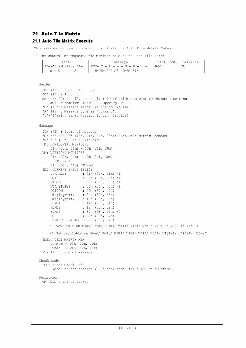
(103/139)
21. Auto Tile Matrix 21.1 Auto Tile Matrix Execute This command is used in order to activate the Auto Tile Matrix Setup. 1) The controller requests the monitor to execute Auto Tile Matrix
Header Message Check code Delimiter SOH-'0'-Monitor ID- '0'-'A'-'1'-'2'
STX-'C'-'A'-'0'-'3'-'0'-'1'- HM-VM-PID-SEL-TMEM-ETX
BCC CR
Header SOH (01h): Start of Header '0' (30h): Reserved Monitor ID: Specify the Monitor ID of which you want to change a setting.
Ex.) If Monitor ID is '1', specify 'A'. '0' (30h): Message sender is the controller. 'A' (41h): Message type is "Command". '1'-'2'(31h, 32h): Message length (18bytes)
Message STX (02h): Start of Message 'C'-'A'-'0'-'3' (43h, 41h, 30h, 33h): Auto Tile Matrix Command '0'-'1' (30h, 31h): Execution HM: HORIZONTAL MONITORS 01h (30h, 31h) - 10h (31h, 30h) VM: VERTICAL MONITORS 01h (30h, 31h) - 10h (31h, 30h) PID: PETTERN ID 01h (30h, 31h) *Fixed SEL: CURRENT INPUT SELECT VGA(RGB) : 01h (30h, 31h) *1 DVI : 03h (30h, 33h) *1 VIDEO : 05h (30h, 35h) *1 VGA(YPbPr) : 0Ch (30h, 43h) *1 OPTION : 0Dh (30h, 44h) DisplayPort1 : 0Fh (30h, 46h) DisplayPort2 : 10h (31h, 30h) HDMI1 : 11h (31h, 31h) HDMI2 : 12h (31h, 32h) HDMI3 : 82h (38h, 32h) *2 MP : 87h (38h, 37h) COMPUTE MODULE : 87h (38h, 37h)
*1 Available on P404/ P484/ P554/ V404/ V484/ V554/ V404-T/ V484-T/ V554-T *2 Not available on P404/ P484/ P554/ V404/ V484/ V554/ V404-T/ V484-T/ V554-T
TMEM: TILE MATRIX MEM COMMON : 00h (30h, 30h)
INPUT : 01h (30h, 31h) ETX (03h): End of Message
Check code BCC: Block Check Code Refer to the section 4.3 “Check code” for a BCC calculation.
Delimiter CR (0Dh): End of packet
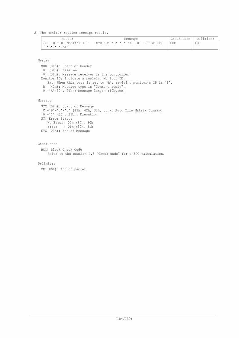
(104/139)
2) The monitor replies receipt result. Header Message Check code Delimiter
SOH-'0'-'0'-Monitor ID- 'B'-'0'-'A'
STX-'C'-'B'-'0'-'3'-'0'-'1'-ST-ETX BCC CR
Header SOH (01h): Start of Header '0' (30h): Reserved '0' (30h): Message receiver is the controller. Monitor ID: Indicate a replying Monitor ID.
Ex.) When this byte is set to ‘A’, replying monitor’s ID is ‘1’. 'B' (42h): Message type is "Command reply". '0'-'A'(30h, 41h): Message length (10bytes)
Message STX (02h): Start of Message 'C'-'B'-'0'-'3' (43h, 42h, 30h, 33h): Auto Tile Matrix Command '0'-'1' (30h, 31h): Execution ST: Error Status No Error : 00h (30h, 30h) Error : 01h (30h, 31h) ETX (03h): End of Message
Check code BCC: Block Check Code
Refer to the section 4.3 “Check code” for a BCC calculation. Delimiter CR (0Dh): End of packet
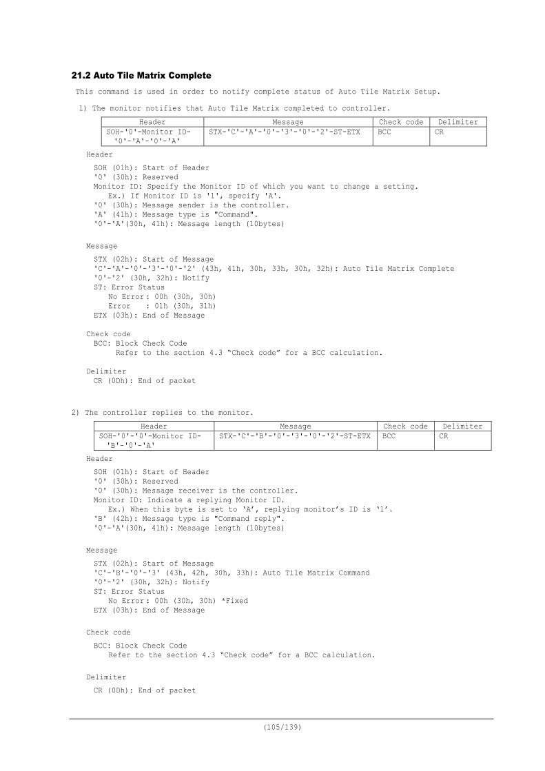
(105/139)
21.2 Auto Tile Matrix Complete This command is used in order to notify complete status of Auto Tile Matrix Setup. 1) The monitor notifies that Auto Tile Matrix completed to controller.
Header Message Check code Delimiter SOH-'0'-Monitor ID- '0'-'A'-'0'-'A'
STX-'C'-'A'-'0'-'3'-'0'-'2'-ST-ETX BCC CR
Header SOH (01h): Start of Header '0' (30h): Reserved Monitor ID: Specify the Monitor ID of which you want to change a setting.
Ex.) If Monitor ID is '1', specify 'A'. '0' (30h): Message sender is the controller. 'A' (41h): Message type is "Command". '0'-'A'(30h, 41h): Message length (10bytes)
Message STX (02h): Start of Message 'C'-'A'-'0'-'3'-'0'-'2' (43h, 41h, 30h, 33h, 30h, 32h): Auto Tile Matrix Complete '0'-'2' (30h, 32h): Notify ST: Error Status No Error : 00h (30h, 30h) Error : 01h (30h, 31h) ETX (03h): End of Message
Check code BCC: Block Check Code Refer to the section 4.3 “Check code” for a BCC calculation.
Delimiter CR (0Dh): End of packet
2) The controller replies to the monitor. Header Message Check code Delimiter
SOH-'0'-'0'-Monitor ID- 'B'-'0'-'A'
STX-'C'-'B'-'0'-'3'-'0'-'2'-ST-ETX BCC CR
Header SOH (01h): Start of Header '0' (30h): Reserved '0' (30h): Message receiver is the controller. Monitor ID: Indicate a replying Monitor ID.
Ex.) When this byte is set to ‘A’, replying monitor’s ID is ‘1’. 'B' (42h): Message type is "Command reply". '0'-'A'(30h, 41h): Message length (10bytes)
Message STX (02h): Start of Message 'C'-'B'-'0'-'3' (43h, 42h, 30h, 33h): Auto Tile Matrix Command '0'-'2' (30h, 32h): Notify ST: Error Status No Error : 00h (30h, 30h) *Fixed ETX (03h): End of Message
Check code BCC: Block Check Code
Refer to the section 4.3 “Check code” for a BCC calculation. Delimiter CR (0Dh): End of packet
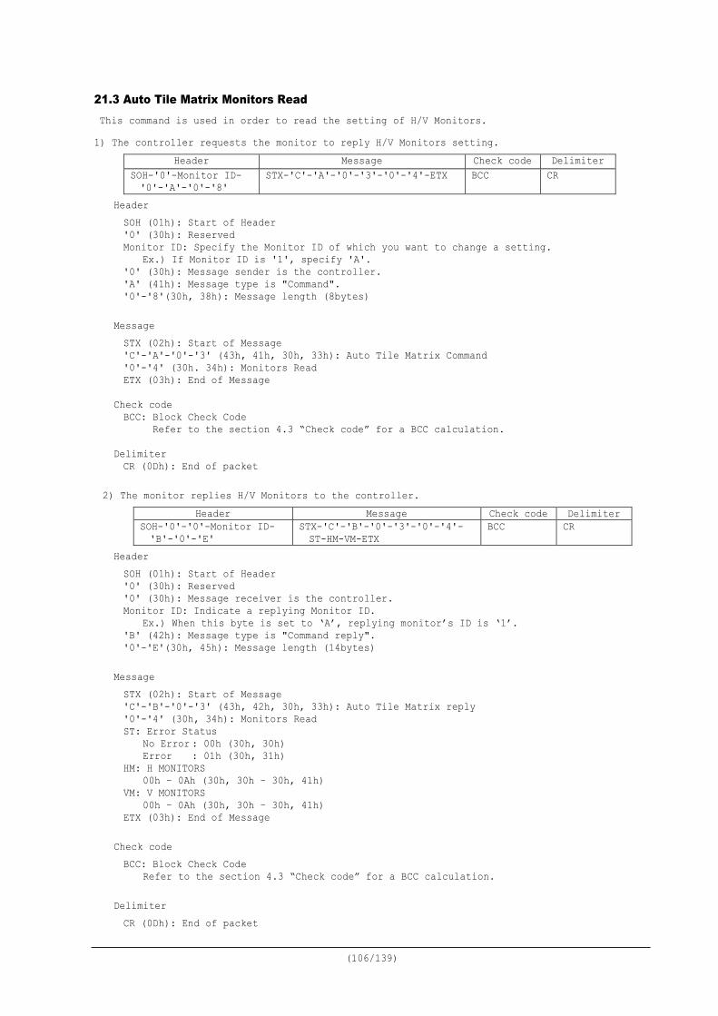
(106/139)
21.3 Auto Tile Matrix Monitors Read This command is used in order to read the setting of H/V Monitors. 1) The controller requests the monitor to reply H/V Monitors setting.
Header Message Check code Delimiter SOH-'0'-Monitor ID- '0'-'A'-'0'-'8'
STX-'C'-'A'-'0'-'3'-'0'-'4'-ETX BCC CR
Header SOH (01h): Start of Header '0' (30h): Reserved Monitor ID: Specify the Monitor ID of which you want to change a setting.
Ex.) If Monitor ID is '1', specify 'A'. '0' (30h): Message sender is the controller. 'A' (41h): Message type is "Command". '0'-'8'(30h, 38h): Message length (8bytes)
Message STX (02h): Start of Message 'C'-'A'-'0'-'3' (43h, 41h, 30h, 33h): Auto Tile Matrix Command '0'-'4' (30h. 34h): Monitors Read ETX (03h): End of Message
Check code BCC: Block Check Code Refer to the section 4.3 “Check code” for a BCC calculation.
Delimiter CR (0Dh): End of packet
2) The monitor replies H/V Monitors to the controller.
Header Message Check code Delimiter SOH-'0'-'0'-Monitor ID- 'B'-'0'-'E'
STX-'C'-'B'-'0'-'3'-'0'-'4'- ST-HM-VM-ETX
BCC CR
Header SOH (01h): Start of Header '0' (30h): Reserved '0' (30h): Message receiver is the controller. Monitor ID: Indicate a replying Monitor ID.
Ex.) When this byte is set to ‘A’, replying monitor’s ID is ‘1’. 'B' (42h): Message type is "Command reply". '0'-'E'(30h, 45h): Message length (14bytes)
Message STX (02h): Start of Message 'C'-'B'-'0'-'3' (43h, 42h, 30h, 33h): Auto Tile Matrix reply '0'-'4' (30h, 34h): Monitors Read ST: Error Status No Error : 00h (30h, 30h) Error : 01h (30h, 31h) HM: H MONITORS 00h – 0Ah (30h, 30h – 30h, 41h) VM: V MONITORS 00h – 0Ah (30h, 30h – 30h, 41h) ETX (03h): End of Message
Check code BCC: Block Check Code
Refer to the section 4.3 “Check code” for a BCC calculation. Delimiter CR (0Dh): End of packet
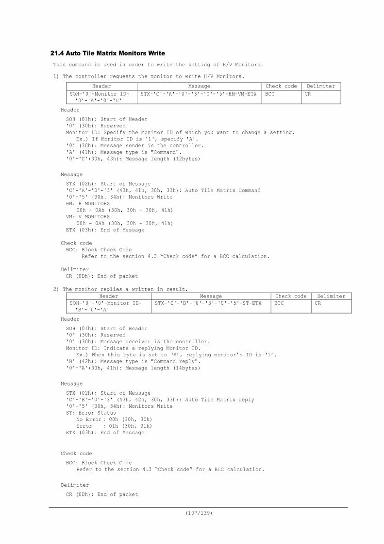
(107/139)
21.4 Auto Tile Matrix Monitors Write This command is used in order to write the setting of H/V Monitors. 1) The controller requests the monitor to write H/V Monitors.
Header Message Check code Delimiter SOH-'0'-Monitor ID- '0'-'A'-'0'-'C'
STX-'C'-'A'-'0'-'3'-'0'-'5'-HM-VM-ETX BCC CR
Header SOH (01h): Start of Header '0' (30h): Reserved Monitor ID: Specify the Monitor ID of which you want to change a setting.
Ex.) If Monitor ID is '1', specify 'A'. '0' (30h): Message sender is the controller. 'A' (41h): Message type is "Command". '0'-'C'(30h, 43h): Message length (12bytes)
Message STX (02h): Start of Message 'C'-'A'-'0'-'3' (43h, 41h, 30h, 33h): Auto Tile Matrix Command '0'-'5' (30h. 34h): Monitors Write HM: H MONITORS 00h – 0Ah (30h, 30h – 30h, 41h) VM: V MONITORS 00h – 0Ah (30h, 30h – 30h, 41h) ETX (03h): End of Message
Check code BCC: Block Check Code Refer to the section 4.3 “Check code” for a BCC calculation.
Delimiter CR (0Dh): End of packet
2) The monitor replies a written in result.
Header Message Check code Delimiter SOH-'0'-'0'-Monitor ID- 'B'-'0'-'A'
STX-'C'-'B'-'0'-'3'-'0'-'5'-ST-ETX BCC CR
Header SOH (01h): Start of Header '0' (30h): Reserved '0' (30h): Message receiver is the controller. Monitor ID: Indicate a replying Monitor ID.
Ex.) When this byte is set to ‘A’, replying monitor’s ID is ‘1’. 'B' (42h): Message type is "Command reply". '0'-'A'(30h, 41h): Message length (14bytes)
Message STX (02h): Start of Message 'C'-'B'-'0'-'3' (43h, 42h, 30h, 33h): Auto Tile Matrix reply '0'-'5' (30h, 34h): Monitors Write ST: Error Status No Error : 00h (30h, 30h) Error : 01h (30h, 31h) ETX (03h): End of Message
Check code BCC: Block Check Code
Refer to the section 4.3 “Check code” for a BCC calculation. Delimiter CR (0Dh): End of packet
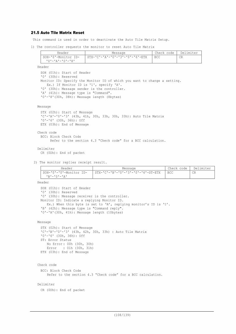
(108/139)
21.5 Auto Tile Matrix Reset This command is used in order to deactivate the Auto Tile Matrix Setup. 1) The controller requests the monitor to reset Auto Tile Matrix
Header Message Check code Delimiter SOH-'0'-Monitor ID- '0'-'A'-'0'-'8'
STX-'C'-'A'-'0'-'3'-'0'-'6'-ETX BCC CR
Header SOH (01h): Start of Header '0' (30h): Reserved Monitor ID: Specify the Monitor ID of which you want to change a setting.
Ex.) If Monitor ID is '1', specify 'A'. '0' (30h): Message sender is the controller. 'A' (41h): Message type is "Command". '0'-'8'(30h, 38h): Message length (8bytes)
Message STX (02h): Start of Message 'C'-'A'-'0'-'3' (43h, 41h, 30h, 33h, 30h, 33h): Auto Tile Matrix '0'-'6' (30h, 36h): Off ETX (03h): End of Message
Check code BCC: Block Check Code Refer to the section 4.3 “Check code” for a BCC calculation.
Delimiter CR (0Dh): End of packet
2) The monitor replies receipt result. Header Message Check code Delimiter
SOH-'0'-'0'-Monitor ID- 'B'-'0'-'A'
STX-'C'-'B'-'0'-'3'-'0'-'6'-ST-ETX BCC CR
Header SOH (01h): Start of Header '0' (30h): Reserved '0' (30h): Message receiver is the controller. Monitor ID: Indicate a replying Monitor ID.
Ex.) When this byte is set to ‘A’, replying monitor’s ID is ‘1’. 'B' (42h): Message type is "Command reply". '0'-'A'(30h, 41h): Message length (10bytes)
Message STX (02h): Start of Message 'C'-'B'-'0'-'3' (43h, 42h, 30h, 33h) : Auto Tile Matrix '0'-'6' (30h, 36h): Off ST: Error Status No Error : 00h (30h, 30h) Error : 01h (30h, 31h) ETX (03h): End of Message
Check code BCC: Block Check Code
Refer to the section 4.3 “Check code” for a BCC calculation. Delimiter CR (0Dh): End of packet
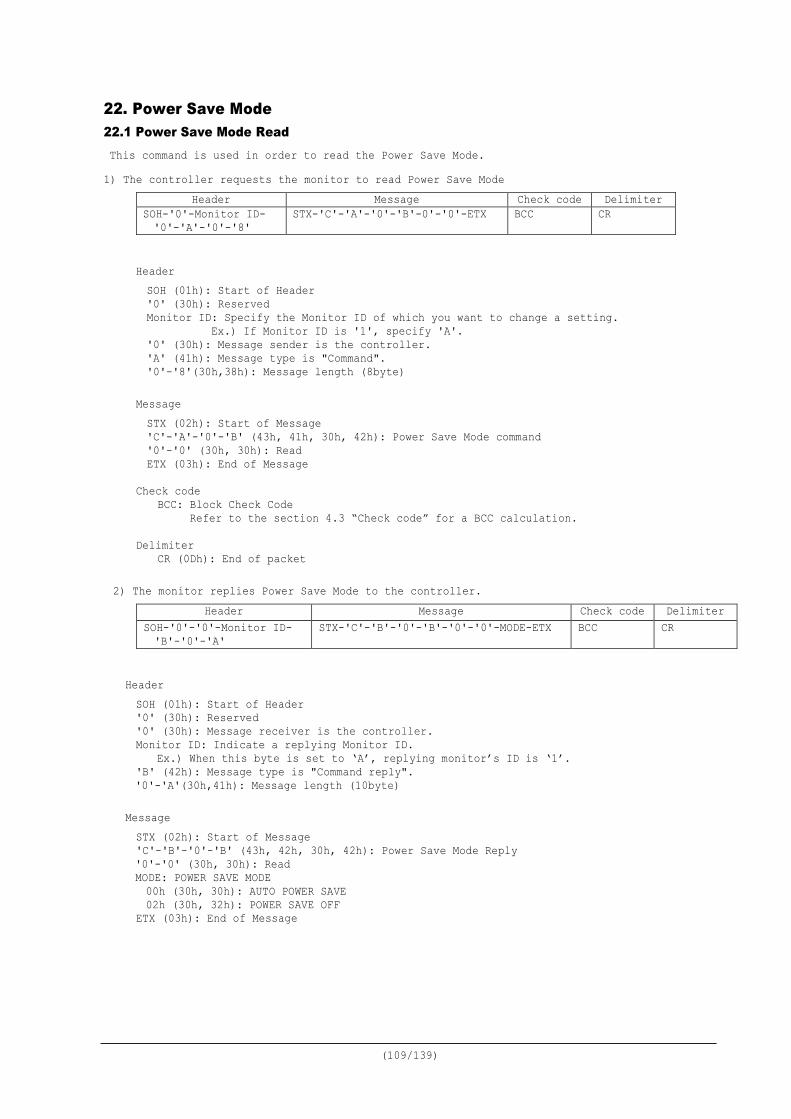
(109/139)
22. Power Save Mode 22.1 Power Save Mode Read This command is used in order to read the Power Save Mode. 1) The controller requests the monitor to read Power Save Mode
Header Message Check code Delimiter SOH-'0'-Monitor ID- '0'-'A'-'0'-'8'
STX-'C'-'A'-'0'-'B'-0'-'0'-ETX BCC CR
Header SOH (01h): Start of Header '0' (30h): Reserved Monitor ID: Specify the Monitor ID of which you want to change a setting.
Ex.) If Monitor ID is '1', specify 'A'. '0' (30h): Message sender is the controller. 'A' (41h): Message type is "Command". '0'-'8'(30h,38h): Message length (8byte)
Message STX (02h): Start of Message 'C'-'A'-'0'-'B' (43h, 41h, 30h, 42h): Power Save Mode command '0'-'0' (30h, 30h): Read ETX (03h): End of Message
Check code
BCC: Block Check Code Refer to the section 4.3 “Check code” for a BCC calculation.
Delimiter
CR (0Dh): End of packet
2) The monitor replies Power Save Mode to the controller. Header Message Check code Delimiter
SOH-'0'-'0'-Monitor ID- 'B'-'0'-'A'
STX-'C'-'B'-'0'-'B'-'0'-'0'-MODE-ETX BCC CR
Header SOH (01h): Start of Header '0' (30h): Reserved '0' (30h): Message receiver is the controller. Monitor ID: Indicate a replying Monitor ID.
Ex.) When this byte is set to ‘A’, replying monitor’s ID is ‘1’. 'B' (42h): Message type is "Command reply". '0'-'A'(30h,41h): Message length (10byte)
Message STX (02h): Start of Message 'C'-'B'-'0'-'B' (43h, 42h, 30h, 42h): Power Save Mode Reply '0'-'0' (30h, 30h): Read MODE: POWER SAVE MODE 00h (30h, 30h): AUTO POWER SAVE 02h (30h, 32h): POWER SAVE OFF ETX (03h): End of Message

(110/139)
Check code BCC: Block Check Code
Refer to the section 4.3 “Check code” for a BCC calculation. Delimiter CR (0Dh): End of packet
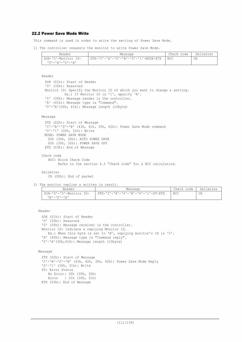
(111/139)
22.2 Power Save Mode Write This command is used in order to write the setting of Power Save Mode. 1) The controller requests the monitor to write Power Save Mode.
Header Message Check code Delimiter SOH-'0'-Monitor ID- '0'-'A'-'0'-'A'
STX-'C'-'A'-'0'-'B'-'0'-'1'-MODE-ETX BCC CR
Header SOH (01h): Start of Header '0' (30h): Reserved Monitor ID: Specify the Monitor ID of which you want to change a setting.
Ex.) If Monitor ID is '1', specify 'A'. '0' (30h): Message sender is the controller. 'A' (41h): Message type is "Command". '0'-'A'(30h, 41h): Message length (10byte)
Message STX (02h): Start of Message 'C'-'A'-'0'-'B' (43h, 41h, 30h, 42h): Power Save Mode command '0'-'1' (30h, 31h): Write MODE: POWER SAVE MODE
00h (30h, 30h): AUTO POWER SAVE 02h (30h, 32h): POWER SAVE OFF ETX (03h): End of Message
Check code
BCC: Block Check Code Refer to the section 4.3 “Check code” for a BCC calculation.
Delimiter
CR (0Dh): End of packet 2) The monitor replies a written in result.
Header Message Check code Delimiter SOH-'0'-'0'-Monitor ID- 'B'-'0'-'A'
STX-'C'-'B'-'0'-'B'-'0'-'1'-ST-ETX BCC CR
Header SOH (01h): Start of Header '0' (30h): Reserved '0' (30h): Message receiver is the controller. Monitor ID: Indicate a replying Monitor ID.
Ex.) When this byte is set to ‘A’, replying monitor’s ID is ‘1’. 'B' (42h): Message type is "Command reply". '0'-'A'(30h,41h): Message length (10byte)
Message STX (02h): Start of Message 'C'-'B'-'0'-'B' (43h, 42h, 30h, 42h): Power Save Mode Reply '0'-'1' (30h, 31h): Write ST: Error Status No Error : 00h (30h, 30h) Error : 01h (30h, 31h) ETX (03h): End of Message

(112/139)
Check code BCC: Block Check Code
Refer to the section 4.3 “Check code” for a BCC calculation.
Delimiter CR (0Dh): End of packet
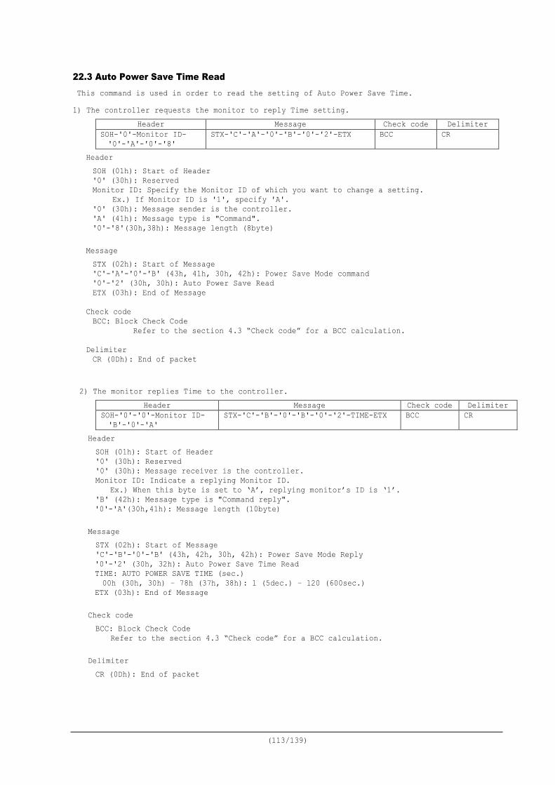
(113/139)
22.3 Auto Power Save Time Read This command is used in order to read the setting of Auto Power Save Time. 1) The controller requests the monitor to reply Time setting.
Header Message Check code Delimiter SOH-'0'-Monitor ID- '0'-'A'-'0'-'8'
STX-'C'-'A'-'0'-'B'-'0'-'2'-ETX BCC CR
Header SOH (01h): Start of Header '0' (30h): Reserved Monitor ID: Specify the Monitor ID of which you want to change a setting.
Ex.) If Monitor ID is '1', specify 'A'. '0' (30h): Message sender is the controller. 'A' (41h): Message type is "Command". '0'-'8'(30h,38h): Message length (8byte)
Message STX (02h): Start of Message 'C'-'A'-'0'-'B' (43h, 41h, 30h, 42h): Power Save Mode command '0'-'2' (30h, 30h): Auto Power Save Read ETX (03h): End of Message
Check code BCC: Block Check Code
Refer to the section 4.3 “Check code” for a BCC calculation.
Delimiter CR (0Dh): End of packet
2) The monitor replies Time to the controller. Header Message Check code Delimiter
SOH-'0'-'0'-Monitor ID- 'B'-'0'-'A'
STX-'C'-'B'-'0'-'B'-'0'-'2'-TIME-ETX BCC CR
Header SOH (01h): Start of Header '0' (30h): Reserved '0' (30h): Message receiver is the controller. Monitor ID: Indicate a replying Monitor ID.
Ex.) When this byte is set to ‘A’, replying monitor’s ID is ‘1’. 'B' (42h): Message type is "Command reply". '0'-'A'(30h,41h): Message length (10byte)
Message STX (02h): Start of Message 'C'-'B'-'0'-'B' (43h, 42h, 30h, 42h): Power Save Mode Reply '0'-'2' (30h, 32h): Auto Power Save Time Read TIME: AUTO POWER SAVE TIME (sec.) 00h (30h, 30h) – 78h (37h, 38h): 1 (5dec.) – 120 (600sec.) ETX (03h): End of Message
Check code BCC: Block Check Code
Refer to the section 4.3 “Check code” for a BCC calculation. Delimiter CR (0Dh): End of packet
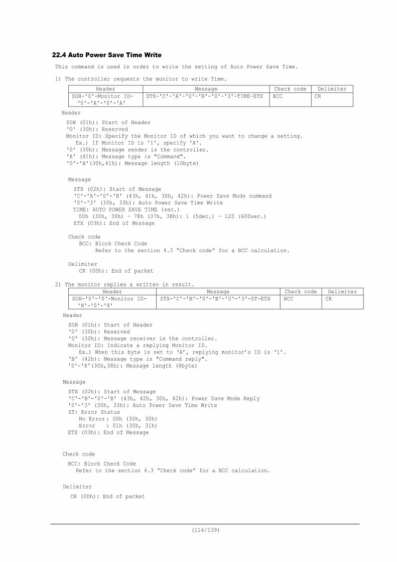
(114/139)
22.4 Auto Power Save Time Write This command is used in order to write the setting of Auto Power Save Time. 1) The controller requests the monitor to write Time.
Header Message Check code Delimiter SOH-'0'-Monitor ID- '0'-'A'-'0'-'A'
STX-'C'-'A'-'0'-'B'-'0'-'3'-TIME-ETX BCC CR
Header SOH (01h): Start of Header '0' (30h): Reserved Monitor ID: Specify the Monitor ID of which you want to change a setting.
Ex.) If Monitor ID is '1', specify 'A'. '0' (30h): Message sender is the controller. 'A' (41h): Message type is "Command". '0'-'A'(30h,41h): Message length (10byte)
Message STX (02h): Start of Message 'C'-'A'-'0'-'B' (43h, 41h, 30h, 42h): Power Save Mode command '0'-'3' (30h, 33h): Auto Power Save Time Write TIME: AUTO POWER SAVE TIME (sec.)
00h (30h, 30h) – 78h (37h, 38h): 1 (5dec.) – 120 (600sec.) ETX (03h): End of Message
Check code
BCC: Block Check Code Refer to the section 4.3 “Check code” for a BCC calculation.
Delimiter
CR (0Dh): End of packet
2) The monitor replies a written in result. Header Message Check code Delimiter
SOH-'0'-'0'-Monitor ID- 'B'-'0'-'8'
STX-'C'-'B'-'0'-'B'-'0'-'3'-ST-ETX BCC CR
Header SOH (01h): Start of Header '0' (30h): Reserved '0' (30h): Message receiver is the controller. Monitor ID: Indicate a replying Monitor ID.
Ex.) When this byte is set to ‘A’, replying monitor’s ID is ‘1’. 'B' (42h): Message type is "Command reply". '0'-'8'(30h,38h): Message length (8byte)
Message STX (02h): Start of Message 'C'-'B'-'0'-'B' (43h, 42h, 30h, 42h): Power Save Mode Reply '0'-'3' (30h, 33h): Auto Power Save Time Write ST: Error Status No Error : 00h (30h, 30h) Error : 01h (30h, 31h) ETX (03h): End of Message
Check code BCC: Block Check Code
Refer to the section 4.3 “Check code” for a BCC calculation.
Delimiter CR (0Dh): End of packet
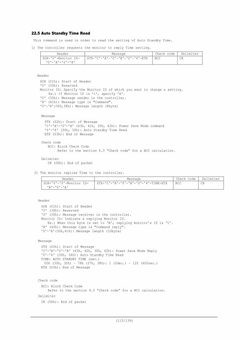
(115/139)
22.5 Auto Standby Time Read This command is used in order to read the setting of Auto Standby Time. 1) The controller requests the monitor to reply Time setting.
Header Message Check code Delimiter SOH-'0'-Monitor ID- '0'-'A'-'0'-'8'
STX-'C'-'A'-'0'-'B'-'0'-'4'-ETX BCC CR
Header SOH (01h): Start of Header '0' (30h): Reserved Monitor ID: Specify the Monitor ID of which you want to change a setting.
Ex.) If Monitor ID is '1', specify 'A'. '0' (30h): Message sender is the controller. 'A' (41h): Message type is "Command". '0'-'8'(30h,38h): Message length (8byte)
Message STX (02h): Start of Message 'C'-'A'-'0'-'B' (43h, 41h, 30h, 42h): Power Save Mode command '0'-'4' (30h, 30h): Auto Standby Time Read ETX (03h): End of Message
Check code
BCC: Block Check Code Refer to the section 4.3 “Check code” for a BCC calculation.
Delimiter
CR (0Dh): End of packet
2) The monitor replies Time to the controller. Header Message Check code Delimiter
SOH-'0'-'0'-Monitor ID- 'B'-'0'-'A'
STX-'C'-'B'-'0'-'B'-'0'-'4'-TIME-ETX BCC CR
Header SOH (01h): Start of Header '0' (30h): Reserved '0' (30h): Message receiver is the controller. Monitor ID: Indicate a replying Monitor ID.
Ex.) When this byte is set to ‘A’, replying monitor’s ID is ‘1’. 'B' (42h): Message type is "Command reply". '0'-'A'(30h,41h): Message length (10byte)
Message STX (02h): Start of Message 'C'-'B'-'0'-'B' (43h, 42h, 30h, 42h): Power Save Mode Reply '0'-'4' (30h, 34h): Auto Standby Time Read TIME: AUTO STANDBY TIME (sec.) 00h (30h, 30h) – 78h (37h, 38h): 1 (5dec.) – 120 (600sec.) ETX (03h): End of Message
Check code BCC: Block Check Code
Refer to the section 4.3 “Check code” for a BCC calculation. Delimiter CR (0Dh): End of packet
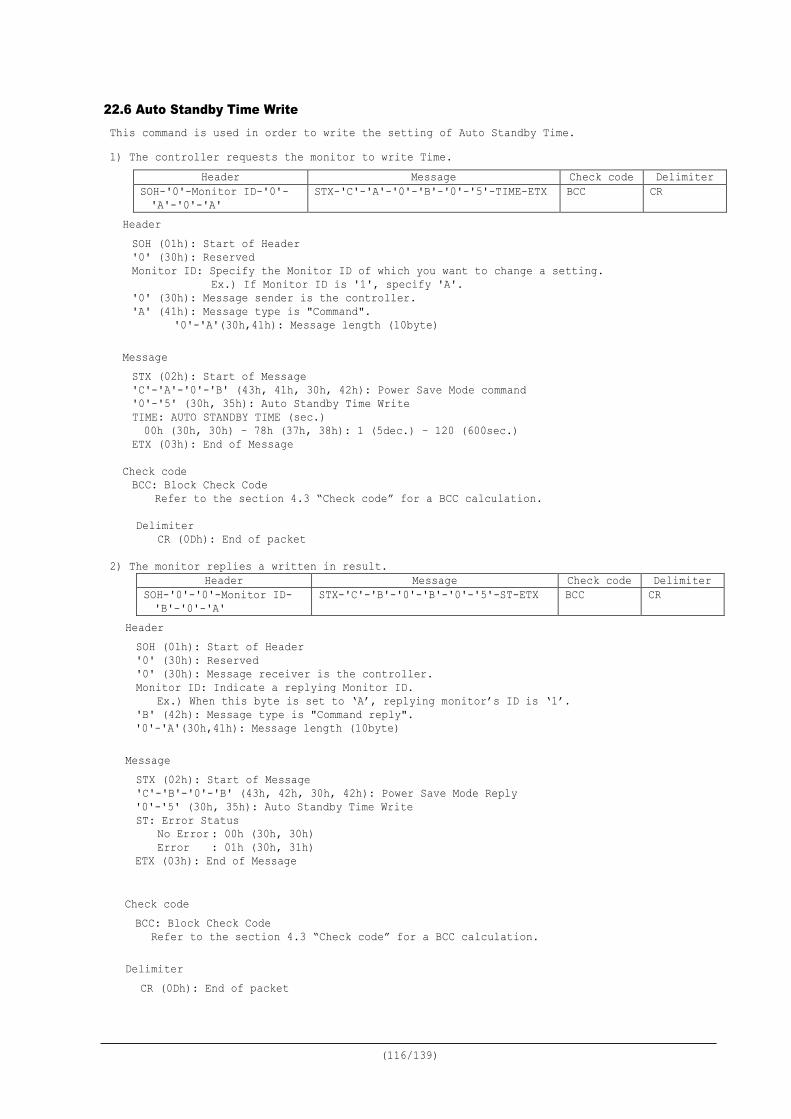
(116/139)
22.6 Auto Standby Time Write This command is used in order to write the setting of Auto Standby Time. 1) The controller requests the monitor to write Time.
Header Message Check code Delimiter SOH-'0'-Monitor ID-'0'- 'A'-'0'-'A'
STX-'C'-'A'-'0'-'B'-'0'-'5'-TIME-ETX BCC CR
Header SOH (01h): Start of Header '0' (30h): Reserved Monitor ID: Specify the Monitor ID of which you want to change a setting.
Ex.) If Monitor ID is '1', specify 'A'. '0' (30h): Message sender is the controller. 'A' (41h): Message type is "Command".
'0'-'A'(30h,41h): Message length (10byte)
Message STX (02h): Start of Message 'C'-'A'-'0'-'B' (43h, 41h, 30h, 42h): Power Save Mode command '0'-'5' (30h, 35h): Auto Standby Time Write TIME: AUTO STANDBY TIME (sec.)
00h (30h, 30h) – 78h (37h, 38h): 1 (5dec.) – 120 (600sec.) ETX (03h): End of Message
Check code BCC: Block Check Code
Refer to the section 4.3 “Check code” for a BCC calculation.
Delimiter CR (0Dh): End of packet
2) The monitor replies a written in result.
Header Message Check code Delimiter SOH-'0'-'0'-Monitor ID- 'B'-'0'-'A'
STX-'C'-'B'-'0'-'B'-'0'-'5'-ST-ETX BCC CR
Header SOH (01h): Start of Header '0' (30h): Reserved '0' (30h): Message receiver is the controller. Monitor ID: Indicate a replying Monitor ID.
Ex.) When this byte is set to ‘A’, replying monitor’s ID is ‘1’. 'B' (42h): Message type is "Command reply". '0'-'A'(30h,41h): Message length (10byte)
Message STX (02h): Start of Message 'C'-'B'-'0'-'B' (43h, 42h, 30h, 42h): Power Save Mode Reply '0'-'5' (30h, 35h): Auto Standby Time Write ST: Error Status No Error : 00h (30h, 30h) Error : 01h (30h, 31h) ETX (03h): End of Message
Check code BCC: Block Check Code
Refer to the section 4.3 “Check code” for a BCC calculation.
Delimiter CR (0Dh): End of packet
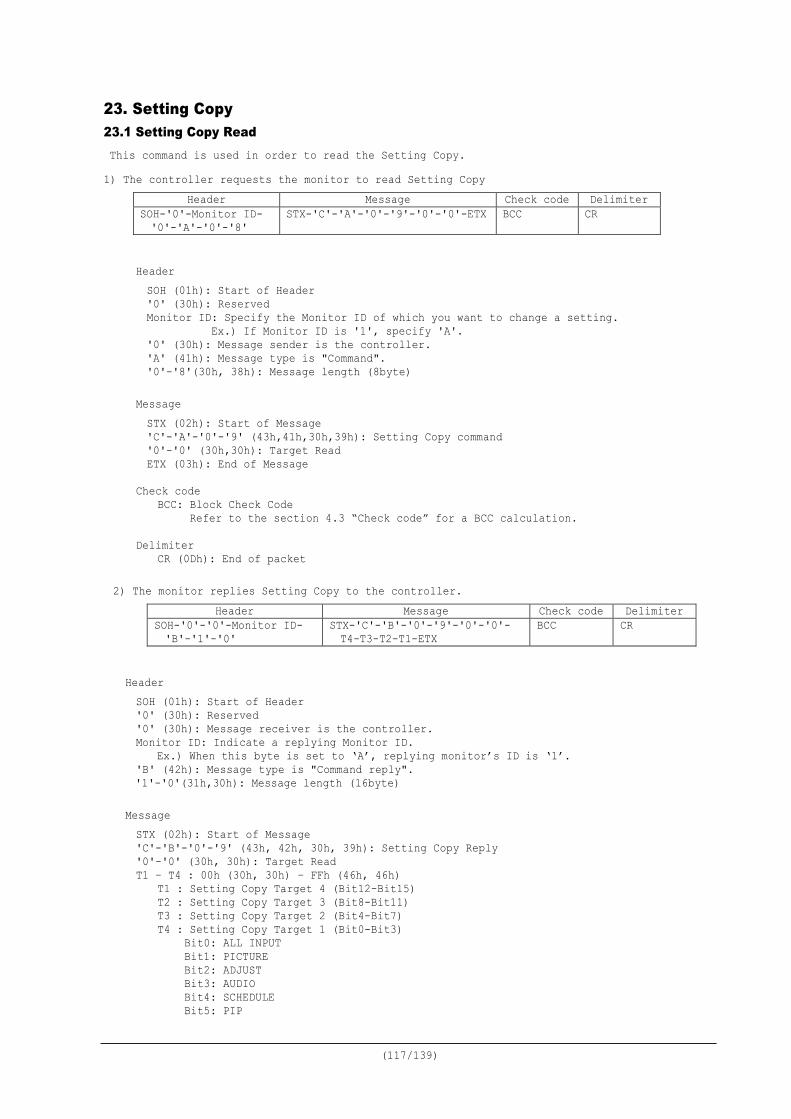
(117/139)
23. Setting Copy 23.1 Setting Copy Read This command is used in order to read the Setting Copy. 1) The controller requests the monitor to read Setting Copy
Header Message Check code Delimiter SOH-'0'-Monitor ID- '0'-'A'-'0'-'8'
STX-'C'-'A'-'0'-'9'-'0'-'0'-ETX BCC CR
Header SOH (01h): Start of Header '0' (30h): Reserved Monitor ID: Specify the Monitor ID of which you want to change a setting.
Ex.) If Monitor ID is '1', specify 'A'. '0' (30h): Message sender is the controller. 'A' (41h): Message type is "Command". '0'-'8'(30h, 38h): Message length (8byte)
Message STX (02h): Start of Message 'C'-'A'-'0'-'9' (43h,41h,30h,39h): Setting Copy command '0'-'0' (30h,30h): Target Read ETX (03h): End of Message
Check code
BCC: Block Check Code Refer to the section 4.3 “Check code” for a BCC calculation.
Delimiter
CR (0Dh): End of packet
2) The monitor replies Setting Copy to the controller. Header Message Check code Delimiter
SOH-'0'-'0'-Monitor ID- 'B'-'1'-'0'
STX-'C'-'B'-'0'-'9'-'0'-'0'- T4-T3-T2-T1-ETX
BCC CR
Header SOH (01h): Start of Header '0' (30h): Reserved '0' (30h): Message receiver is the controller. Monitor ID: Indicate a replying Monitor ID.
Ex.) When this byte is set to ‘A’, replying monitor’s ID is ‘1’. 'B' (42h): Message type is "Command reply". '1'-'0'(31h,30h): Message length (16byte)
Message STX (02h): Start of Message 'C'-'B'-'0'-'9' (43h, 42h, 30h, 39h): Setting Copy Reply '0'-'0' (30h, 30h): Target Read T1 – T4 : 00h (30h, 30h) – FFh (46h, 46h)
T1 : Setting Copy Target 4 (Bit12-Bit15) T2 : Setting Copy Target 3 (Bit8-Bit11) T3 : Setting Copy Target 2 (Bit4-Bit7) T4 : Setting Copy Target 1 (Bit0-Bit3)
Bit0: ALL INPUT Bit1: PICTURE Bit2: ADJUST Bit3: AUDIO Bit4: SCHEDULE Bit5: PIP
(118/139)
Bit6: OSD Bit7: MULTI DISP Bit8: PROTECT Bit9: EXT-CTRL Bit10: ADVANCED Bit11: ADVANCED2 Bit12: HTTP Bit13: Reserve Bit14: Reserve Bit15: Reserve
Ex.) Setting the following value for T4 Bit0: ALL INPUT is OFF (0). Bit1: PICTURE is OFF (0). Bit2: ADJUST is ON (1). Bit3: AUDIO is ON (1). Step 1: Put above bit in following order.
Bit3-Bit2-Bit1-Bit0 Value: 1100
Step 2: Write the value of Step 1 by a hexadecimal number. Value: 0Ch
Step 3: Encode the value of Step 2 to ASCII characters. Value: '0' and 'C' (30h and 43h)
ETX (03h): End of Message
Check code
BCC: Block Check Code Refer to the section 4.3 “Check code” for a BCC calculation.
Delimiter CR (0Dh): End of packet
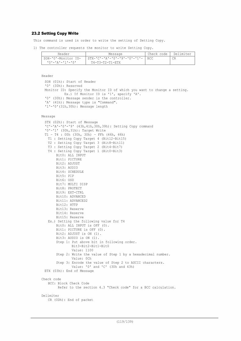
(119/139)
23.2 Setting Copy Write This command is used in order to write the setting of Setting Copy. 1) The controller requests the monitor to write Setting Copy.
Header Message Check code Delimiter SOH-'0'-Monitor ID- '0'-'A'-'1'-'0'
STX-'C'-'A'-'0'-'9'-'0'-'1'- T4-T3-T2-T1-ETX
BCC CR
Header SOH (01h): Start of Header '0' (30h): Reserved Monitor ID: Specify the Monitor ID of which you want to change a setting.
Ex.) If Monitor ID is '1', specify 'A'. '0' (30h): Message sender is the controller. 'A' (41h): Message type is "Command". '1'-'0'(31h,30h): Message length
Message STX (02h): Start of Message 'C'-'A'-'0'-'9' (43h,41h,30h,39h): Setting Copy command '0'-'1' (30h,31h): Target Write T1 – T4 : 00h (30h, 30h) – FFh (46h, 46h) T1 : Setting Copy Target 4 (Bit12-Bit15) T2 : Setting Copy Target 3 (Bit8-Bit11) T3 : Setting Copy Target 2 (Bit4-Bit7) T4 : Setting Copy Target 1 (Bit0-Bit3)
Bit0: ALL INPUT Bit1: PICTURE Bit2: ADJUST Bit3: AUDIO Bit4: SCHEDULE Bit5: PIP Bit6: OSD Bit7: MULTI DISP Bit8: PROTECT Bit9: EXT-CTRL Bit10: ADVANCED Bit11: ADVANCED2 Bit12: HTTP Bit13: Reserve Bit14: Reserve Bit15: Reserve
Ex.) Setting the following value for T4 Bit0: ALL INPUT is OFF (0). Bit1: PICTURE is OFF (0). Bit2: ADJUST is ON (1). Bit3: AUDIO is ON (1). Step 1: Put above bit in following order.
Bit3-Bit2-Bit1-Bit0 Value: 1100
Step 2: Write the value of Step 1 by a hexadecimal number. Value: 0Ch
Step 3: Encode the value of Step 2 to ASCII characters. Value: '0' and 'C' (30h and 43h)
ETX (03h): End of Message
Check code BCC: Block Check Code Refer to the section 4.3 “Check code” for a BCC calculation.
Delimiter
CR (0Dh): End of packet
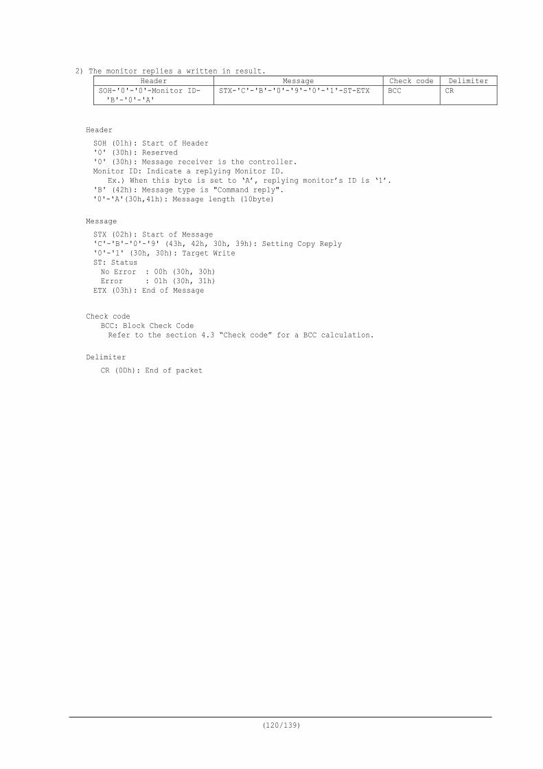
(120/139)
2) The monitor replies a written in result. Header Message Check code Delimiter
SOH-'0'-'0'-Monitor ID- 'B'-'0'-'A'
STX-'C'-'B'-'0'-'9'-'0'-'1'-ST-ETX BCC CR
Header SOH (01h): Start of Header '0' (30h): Reserved '0' (30h): Message receiver is the controller. Monitor ID: Indicate a replying Monitor ID.
Ex.) When this byte is set to ‘A’, replying monitor’s ID is ‘1’. 'B' (42h): Message type is "Command reply". '0'-'A'(30h,41h): Message length (10byte)
Message STX (02h): Start of Message 'C'-'B'-'0'-'9' (43h, 42h, 30h, 39h): Setting Copy Reply '0'-'1' (30h, 30h): Target Write ST: Status No Error : 00h (30h, 30h) Error : 01h (30h, 31h)
ETX (03h): End of Message
Check code BCC: Block Check Code Refer to the section 4.3 “Check code” for a BCC calculation.
Delimiter
CR (0Dh): End of packet
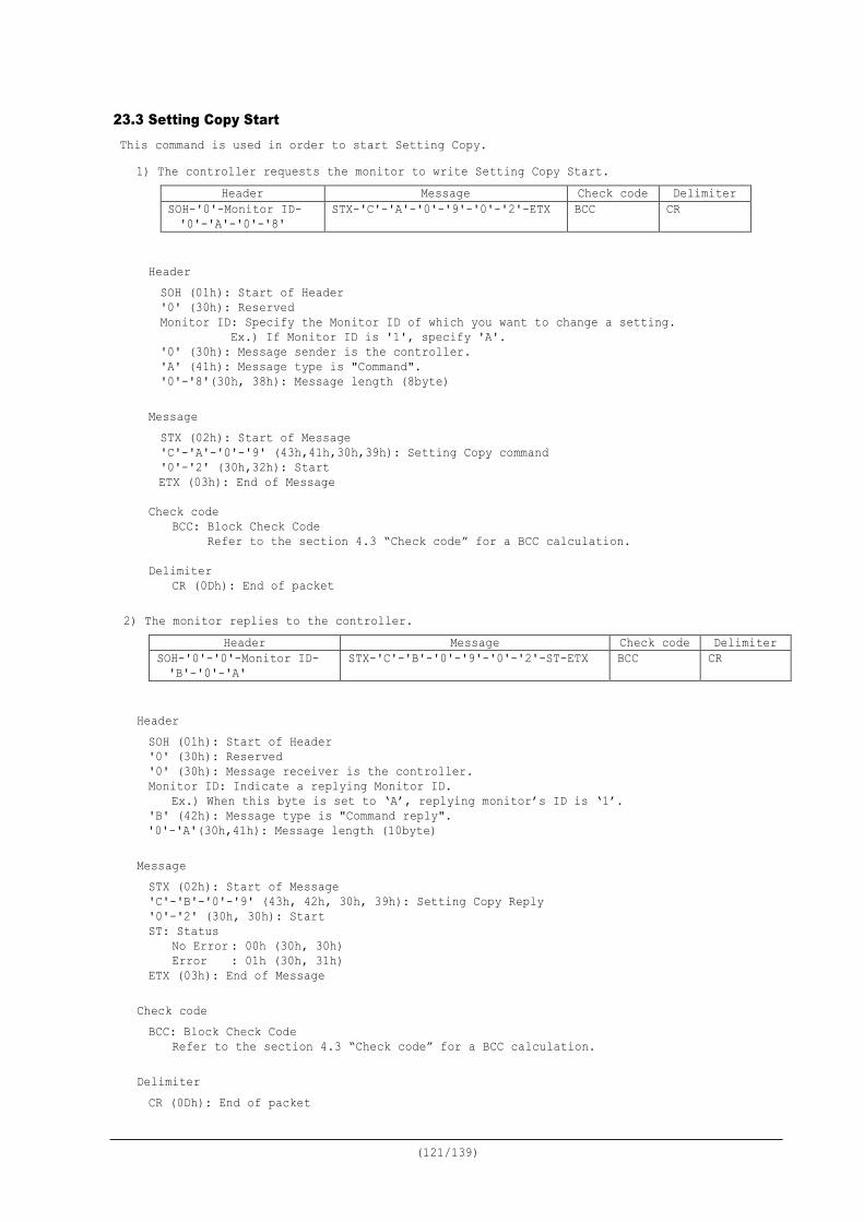
(121/139)
23.3 Setting Copy Start This command is used in order to start Setting Copy.
1) The controller requests the monitor to write Setting Copy Start. Header Message Check code Delimiter
SOH-'0'-Monitor ID- '0'-'A'-'0'-'8'
STX-'C'-'A'-'0'-'9'-'0'-'2'-ETX BCC CR
Header SOH (01h): Start of Header '0' (30h): Reserved Monitor ID: Specify the Monitor ID of which you want to change a setting.
Ex.) If Monitor ID is '1', specify 'A'. '0' (30h): Message sender is the controller. 'A' (41h): Message type is "Command". '0'-'8'(30h, 38h): Message length (8byte)
Message STX (02h): Start of Message 'C'-'A'-'0'-'9' (43h,41h,30h,39h): Setting Copy command '0'-'2' (30h,32h): Start ETX (03h): End of Message
Check code
BCC: Block Check Code Refer to the section 4.3 “Check code” for a BCC calculation.
Delimiter
CR (0Dh): End of packet 2) The monitor replies to the controller.
Header Message Check code Delimiter SOH-'0'-'0'-Monitor ID- 'B'-'0'-'A'
STX-'C'-'B'-'0'-'9'-'0'-'2'-ST-ETX BCC CR
Header SOH (01h): Start of Header '0' (30h): Reserved '0' (30h): Message receiver is the controller. Monitor ID: Indicate a replying Monitor ID.
Ex.) When this byte is set to ‘A’, replying monitor’s ID is ‘1’. 'B' (42h): Message type is "Command reply". '0'-'A'(30h,41h): Message length (10byte)
Message STX (02h): Start of Message 'C'-'B'-'0'-'9' (43h, 42h, 30h, 39h): Setting Copy Reply '0'-'2' (30h, 30h): Start ST: Status
No Error : 00h (30h, 30h) Error : 01h (30h, 31h)
ETX (03h): End of Message
Check code BCC: Block Check Code
Refer to the section 4.3 “Check code” for a BCC calculation. Delimiter CR (0Dh): End of packet
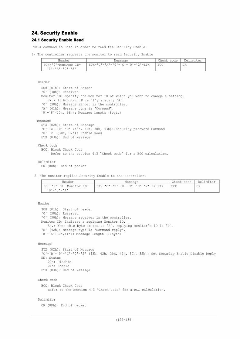
(122/139)
24. Security Enable 24.1 Security Enable Read This command is used in order to read the Security Enable. 1) The controller requests the monitor to read Security Enable
Header Message Check code Delimiter SOH-'0'-Monitor ID- '0'-'A'-'0'-'8'
STX-'C'-'A'-'0'-'C'-'0'-'2'-ETX BCC CR
Header SOH (01h): Start of Header '0' (30h): Reserved Monitor ID: Specify the Monitor ID of which you want to change a setting.
Ex.) If Monitor ID is '1', specify 'A'. '0' (30h): Message sender is the controller. 'A' (41h): Message type is "Command". '0'-'8'(30h, 38h): Message length (8byte)
Message STX (02h): Start of Message 'C'-'A'-'0'-'C' (43h, 41h, 30h, 43h): Security password Command '0'-'2' (30h, 32h): Enable Read ETX (03h): End of Message
Check code BCC: Block Check Code Refer to the section 4.3 “Check code” for a BCC calculation.
Delimiter CR (0Dh): End of packet
2) The monitor replies Security Enable to the controller.
Header Message Check code Delimiter SOH-'0'-'0'-Monitor ID- 'B'-'0'-'A'
STX-'C'-'B'-'0'-'C'-'0'-'2'-EN-ETX BCC CR
Header SOH (01h): Start of Header '0' (30h): Reserved '0' (30h): Message receiver is the controller. Monitor ID: Indicate a replying Monitor ID.
Ex.) When this byte is set to ‘A’, replying monitor’s ID is ‘1’. 'B' (42h): Message type is "Command reply". '0'-'A'(30h,41h): Message length (10byte)
Message STX (02h): Start of Message 'C'-'B'-'0'-'C'-'0'-'2' (43h, 42h, 30h, 41h, 30h, 32h): Get Security Enable Disable Reply EN: Status 00h: Disable 01h: Enable ETX (03h): End of Message
Check code BCC: Block Check Code
Refer to the section 4.3 “Check code” for a BCC calculation. Delimiter CR (0Dh): End of packet
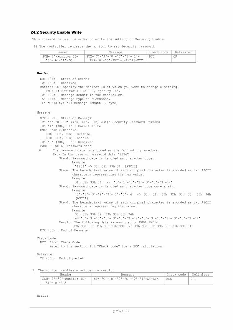
(123/139)
24.2 Security Enable Write This command is used in order to write the setting of Security Enable. 1) The controller requests the monitor to set Security password.
Header Message Check code Delimiter SOH-'0'-Monitor ID- '0'-'A'-'1'-'C'
STX-'C'-'A'-'0'-'C'-'0'-'1'- ENA-'0'-'0'-PWD1-…-PWD16-ETX
BCC CR
Header SOH (01h): Start of Header '0' (30h): Reserved Monitor ID: Specify the Monitor ID of which you want to change a setting.
Ex.) If Monitor ID is '1', specify 'A'. '0' (30h): Message sender is the controller. 'A' (41h): Message type is "Command". '1'-'C'(31h,43h): Message length (28byte)
Message STX (02h): Start of Message 'C'-'A'-'0'-'C' (43h, 41h, 30h, 43h): Security Password Command '0'-'1' (30h, 31h): Enable Write ENA: Enable/Disable 00h (30h, 30h): Disable 01h (30h, 31h): Enable '0'-'0' (30h, 30h): Reserved PWD1 – PWD16: Password data The password data is encoded as the following procedure.
Ex.) In the case of password data "1234" Step1: Password data is handled as character code.
Example: "1234" -> 31h 32h 33h 34h (ASCII)
Step2: The hexadecimal value of each original character is encoded as two ASCII characters representing the hex value. Example: 31h 32h 33h 34h -> '3'-'1'-'3'-'2'-'3'-'3'-'3'-'4'
Step3: Password data is handled as character code once again. Example: '3'-'1'-'3'-'2'-'3'-'3'-'3'-'4' -> 33h 31h 33h 32h 33h 33h 33h 34h (ASCII)
Step4: The hexadecimal value of each original character is encoded as two ASCII characters representing the value. Example: 33h 31h 33h 32h 33h 33h 33h 34h -> '3'-'3'-'3'-'1'-'3'-'3'-'3'-'2'-'3'-'3'-'3'-'3'-'3'-'3'-'3'-'4'
Result: The following data is assigned to PWD1-PWD16. 33h 33h 33h 31h 33h 33h 33h 32h 33h 33h 33h 33h 33h 33h 33h 34h
ETX (03h): End of Message
Check code BCC: Block Check Code Refer to the section 4.3 “Check code” for a BCC calculation.
Delimiter CR (0Dh): End of packet
2) The monitor replies a written in result. Header Message Check code Delimiter
SOH-'0'-'0'-Monitor ID- 'B'-'0'-'A'
STX-'C'-'B'-'0'-'C'-'0'-'1'-ST-ETX BCC CR
Header
(124/139)
SOH (01h): Start of Header '0' (30h): Reserved '0' (30h): Message receiver is the controller. Monitor ID: Indicate a replying Monitor ID.
Ex.) When this byte is set to ‘A’, replying monitor’s ID is ‘1’. 'B' (42h): Message type is "Command reply". '0'-'A'(30h,41h): Message length (10byte)
Message STX (02h): Start of Message 'C'-'B'-'0'-'C' (43h, 42h, 30h, 43h): Security password Reply Command '0'-'1' (30h, 31h): Enable Write ST: Error Status 00h: No Error 01h: Error ETX (03h): End of Message
Check code BCC: Block Check Code
Refer to the section 4.3 “Check code” for a BCC calculation. Delimiter CR (0Dh): End of packet
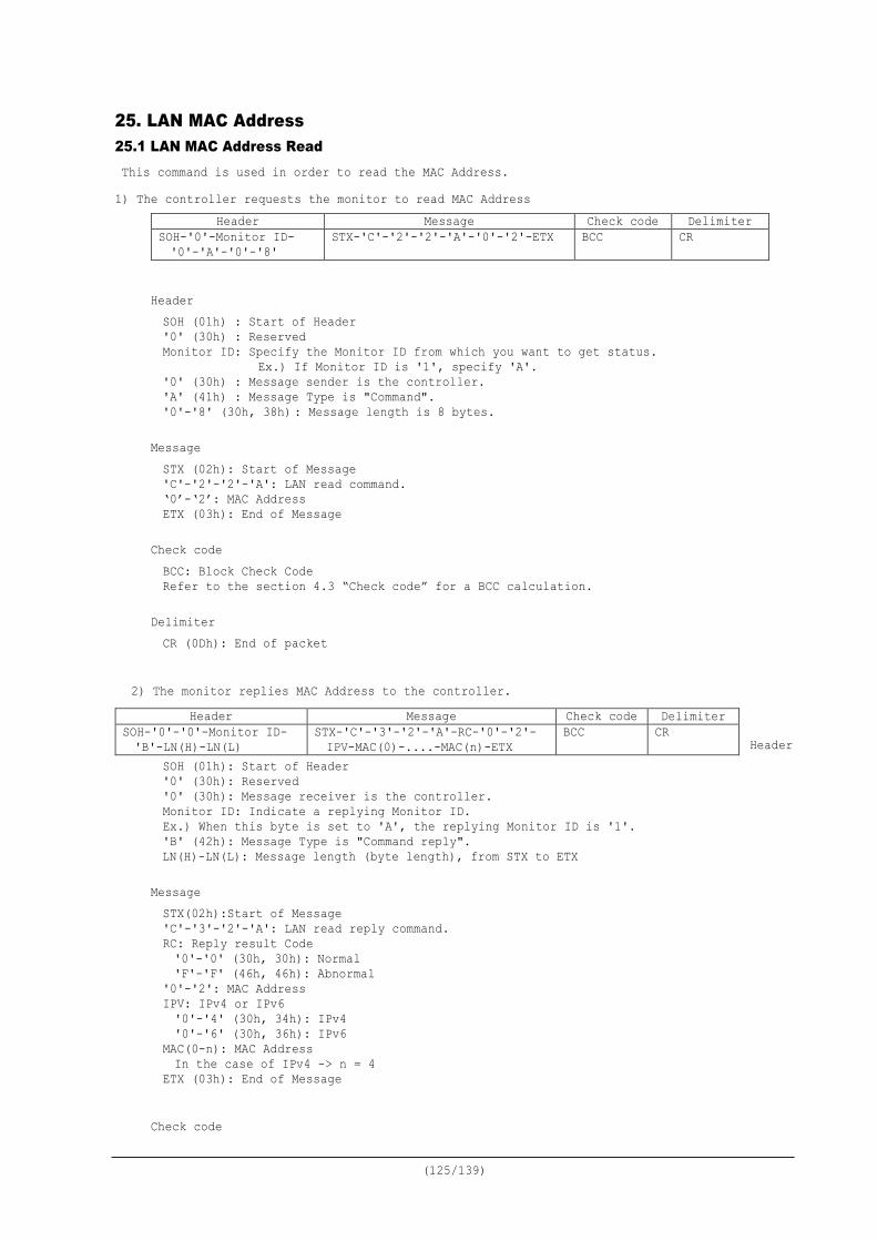
(125/139)
25. LAN MAC Address 25.1 LAN MAC Address Read This command is used in order to read the MAC Address. 1) The controller requests the monitor to read MAC Address
Header Message Check code Delimiter SOH-'0'-Monitor ID- '0'-'A'-'0'-'8'
STX-'C'-'2'-'2'-'A'-'0'-'2'-ETX BCC CR
Header SOH (01h) : Start of Header '0' (30h) : Reserved Monitor ID: Specify the Monitor ID from which you want to get status.
Ex.) If Monitor ID is '1', specify 'A'. '0' (30h) : Message sender is the controller. 'A' (41h) : Message Type is "Command". '0'-'8' (30h, 38h) : Message length is 8 bytes.
Message STX (02h): Start of Message 'C'-'2'-'2'-'A': LAN read command. ‘0’-‘2’: MAC Address ETX (03h): End of Message
Check code BCC: Block Check Code Refer to the section 4.3 “Check code” for a BCC calculation.
Delimiter CR (0Dh): End of packet
2) The monitor replies MAC Address to the controller.
Header
SOH (01h): Start of Header '0' (30h): Reserved '0' (30h): Message receiver is the controller. Monitor ID: Indicate a replying Monitor ID. Ex.) When this byte is set to 'A', the replying Monitor ID is '1'. 'B' (42h): Message Type is "Command reply". LN(H)-LN(L): Message length (byte length), from STX to ETX
Message STX(02h):Start of Message 'C'-'3'-'2'-'A': LAN read reply command. RC: Reply result Code '0'-'0' (30h, 30h): Normal 'F'-'F' (46h, 46h): Abnormal
'0'-'2': MAC Address IPV: IPv4 or IPv6 '0'-'4' (30h, 34h): IPv4 '0'-'6' (30h, 36h): IPv6 MAC(0-n): MAC Address In the case of IPv4 -> n = 4 ETX (03h): End of Message
Check code
Header Message Check code Delimiter SOH-'0'-'0'-Monitor ID- 'B'-LN(H)-LN(L)
STX-'C'-'3'-'2'-'A'-RC-'0'-'2'- IPV-MAC(0)-....-MAC(n)-ETX
BCC CR

(126/139)
BCC: Block Check Code Refer to the section 4.3 “Check code” for a BCC calculation.
Delimiter CR (0Dh): End of packet
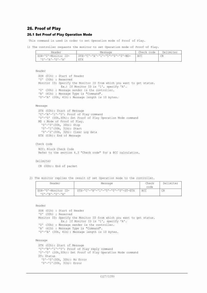
(127/139)
26. Proof of Play 26.1 Set Proof of Play Operation Mode This command is used in order to set Operation mode of Proof of Play. 1) The controller requests the monitor to set Operation mode of Proof of Play.
Header Message Check code Delimiter SOH-'0'-Monitor ID- '0'-'A'-'0'-'A'
STX-'C'-'A'-'1'-'5'-'0'-'0'-MD-ETX
BCC CR
Header SOH (01h) : Start of Header '0' (30h) : Reserved Monitor ID: Specify the Monitor ID from which you want to get status.
Ex.) If Monitor ID is '1', specify 'A'. '0' (30h) : Message sender is the controller. 'A' (41h) : Message Type is "Command". '0'-'A' (30h, 41h) : Message length is 10 bytes.
Message STX (02h): Start of Message 'C'-'A'-'1'-'5': Proof of Play command '0'-'0' (30h,30h): Set Proof of Play Operation Mode command MD : Mode of Proof of Play.
'0'-'0'(30h, 30h): Stop '0'-'1'(30h, 31h): Start '0'-'2'(30h, 32h): Clear Log data ETX (03h): End of Message
Check code BCC: Block Check Code Refer to the section 4.3 “Check code” for a BCC calculation.
Delimiter CR (0Dh): End of packet
2) The monitor replies the result of set Operation mode to the controller.
Header Message Check code
Delimiter
SOH-'0'-Monitor ID- '0'-'B'-'0'-'A'
STX-'C'-'B'-'1'-'5'-'0'-'0'-ST-ETX BCC CR
Header SOH (01h) : Start of Header '0' (30h) : Reserved Monitor ID: Specify the Monitor ID from which you want to get status.
Ex.) If Monitor ID is '1', specify 'A'. '0' (30h) : Message sender is the controller. 'A' (41h) : Message Type is "Command". '0'-'A' (30h, 41h) : Message length is 10 bytes.
Message STX (02h): Start of Message 'C'-'B'-'1'-'5': Proof of Play reply command '0'-'0' (30h,30h): Set Proof of Play Operation Mode command ST: Status '0'-'0'(30h, 30h): No Error '0'-'1'(30h, 31h): Error

(128/139)
'0'-'2'(30h, 32h): Already Start/Stop/Clear ETX (03h): End of Message
Check code BCC: Block Check Code Refer to the section 4.3 “Check code” for a BCC calculation.
Delimiter CR (0Dh): End of packet
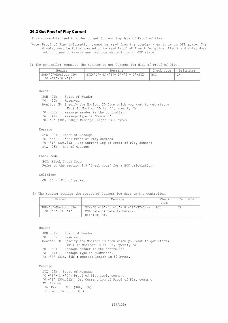
(129/139)
26.2 Get Proof of Play Current This command is used in order to get Current log data of Proof of Play. Note:Proof of Play information cannot be read from the display when it is in OFF state. The
display must be fully powered on to read Proof of Play information. Also the display does not continue to create any new logs while it is in OFF state.
1) The controller requests the monitor to get Current log data of Proof of Play.
Header Message Check code Delimiter SOH-'0'-Monitor ID- '0'-'A'-'0'-'8'
STX-'C'-'A'-'1'-'5'-'0'-'1'-ETX BCC CR
Header SOH (01h) : Start of Header '0' (30h) : Reserved Monitor ID: Specify the Monitor ID from which you want to get status.
Ex.) If Monitor ID is '1', specify 'A'. '0' (30h) : Message sender is the controller. 'A' (41h) : Message Type is "Command". '0'-'8' (30h, 38h) : Message length is 8 bytes.
Message STX (02h): Start of Message 'C'-'A'-'1'-'5': Proof of Play command '0'-'1' (30h,31h): Get Current log of Proof of Play command ETX (03h): End of Message
Check code BCC: Block Check Code Refer to the section 4.3 “Check code” for a BCC calculation.
Delimiter CR (0Dh): End of packet
2) The monitor replies the result of Current log data to the controller.
Header Message Check code
Delimiter
SOH-'0'-Monitor ID- '0'-'B'-'3'-'4'
STX-'C'-'B'-'1'-'5'-'0'-'1'-ST-CNH- CNL-Data(0)-Data(1)-Data(2)--- Data(18)-ETX
BCC CR
Header SOH (01h) : Start of Header '0' (30h) : Reserved Monitor ID: Specify the Monitor ID from which you want to get status.
Ex.) If Monitor ID is '1', specify 'A'. '0' (30h) : Message sender is the controller. 'A' (41h) : Message Type is "Command". '3'-'4' (33h, 34h) : Message length is 52 bytes.
Message STX (02h): Start of Message 'C'-'B'-'1'-'5': Proof of Play reply command '0'-'1' (30h,31h): Get Current log of Proof of Play command ST: Status
No Error : 00h (30h, 30h) Error: 01h (30h, 31h)
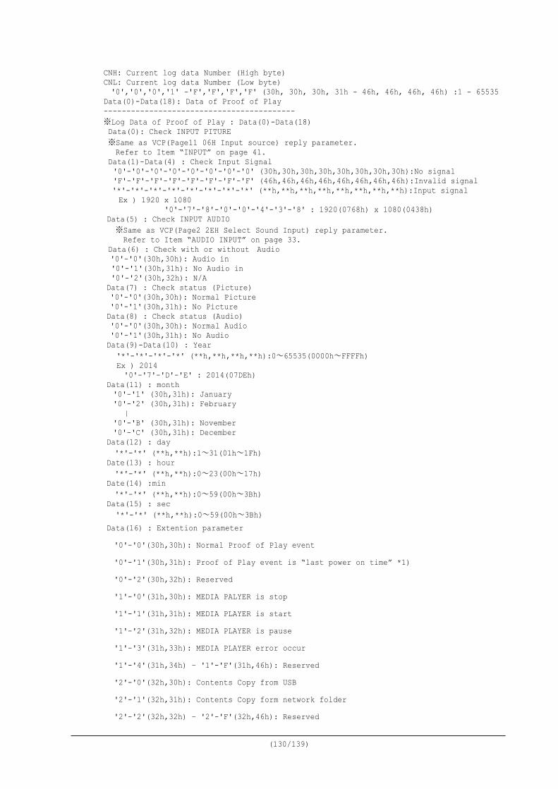
(130/139)
CNH: Current log data Number (High byte) CNL: Current log data Number (Low byte) '0','0','0','1' -'F','F','F','F' (30h, 30h, 30h, 31h - 46h, 46h, 46h, 46h) :1 - 65535 Data(0)-Data(18): Data of Proof of Play ------------------------------------------ ※Log Data of Proof of Play : Data(0)-Data(18) Data(0): Check INPUT PITURE ※Same as VCP(Page11 06H Input source) reply parameter. Refer to Item “INPUT” on page 41. Data(1)-Data(4) : Check Input Signal '0'-'0'-'0'-'0'-'0'-'0'-'0'-'0' (30h,30h,30h,30h,30h,30h,30h,30h):No signal 'F'-'F'-'F'-'F'-'F'-'F'-'F'-'F' (46h,46h,46h,46h,46h,46h,46h,46h):Invalid signal '*'-'*'-'*'-'*'-'*'-'*'-'*'-'*' (**h,**h,**h,**h,**h,**h,**h,**h):Input signal Ex ) 1920 x 1080
'0'-'7'-'8'-'0'-'0'-'4'-'3'-'8' : 1920(0768h) x 1080(0438h) Data(5) : Check INPUT AUDIO ※Same as VCP(Page2 2EH Select Sound Input) reply parameter. Refer to Item “AUDIO INPUT” on page 33. Data(6) : Check with or without Audio '0'-'0'(30h,30h): Audio in '0'-'1'(30h,31h): No Audio in '0'-'2'(30h,32h): N/A
Data(7) : Check status (Picture) '0'-'0'(30h,30h): Normal Picture '0'-'1'(30h,31h): No Picture Data(8) : Check status (Audio) '0'-'0'(30h,30h): Normal Audio '0'-'1'(30h,31h): No Audio Data(9)-Data(10) : Year
'*'-'*'-'*'-'*' (**h,**h,**h,**h):0~65535(0000h~FFFFh) Ex ) 2014 '0'-'7'-'D'-'E' : 2014(07DEh)
Data(11) : month '0'-'1' (30h,31h): January '0'-'2' (30h,31h): February | '0'-'B' (30h,31h): November '0'-'C' (30h,31h): December
Data(12) : day '*'-'*' (**h,**h):1~31(01h~1Fh)
Date(13) : hour '*'-'*' (**h,**h):0~23(00h~17h)
Date(14) :min '*'-'*' (**h,**h):0~59(00h~3Bh)
Data(15) : sec '*'-'*' (**h,**h):0~59(00h~3Bh)
Data(16) : Extention parameter '0'-'0'(30h,30h): Normal Proof of Play event '0'-'1'(30h,31h): Proof of Play event is “last power on time” *1) '0'-'2'(30h,32h): Reserved '1'-'0'(31h,30h): MEDIA PALYER is stop '1'-'1'(31h,31h): MEDIA PLAYER is start '1'-'2'(31h,32h): MEDIA PLAYER is pause '1'-'3'(31h,33h): MEDIA PLAYER error occur '1'-'4'(31h,34h) – '1'-'F'(31h,46h): Reserved '2'-'0'(32h,30h): Contents Copy from USB '2'-'1'(32h,31h): Contents Copy form network folder '2'-'2'(32h,32h) – '2'-'F'(32h,46h): Reserved
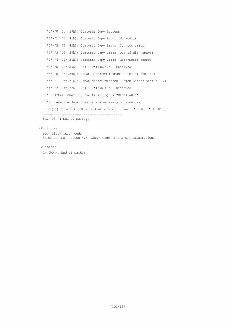
(131/139)
'3'-'0'(33h,30h): Contents Copy Success '3'-'1'(33h,31h): Contents Copy Error (No media) '3'-'2'(33h,32h): Contents Copy Error (Connect error) '3'-'3'(33h,33h): Contents Copy Error (Out of disk space) '3'-'4'(33h,34h): Contents Copy Error (Read/Write error) '3'-'5'(32h,35h) – '3'-'F'(33h,46h): Reserved '4'-'0'(34h,30h): Human detected (Human sensor Status) *2) '4'-'1'(34h,31h): Human detect cleared (Human Sensor Status) *2) '4'-'2'(34h,32h) – '4'-'F'(34h,46h): Reserved *1: After Power ON, the first log is "Data16=01h". *2: Save the Human Sensor status every 30 minuites. Data(17)-Data(18) : Reserve(future use : always '0'-0'-0'-0'-0'-0') ------------------------------------------ ETX (03h): End of Message
Check code BCC: Block Check Code Refer to the section 4.3 “Check code” for a BCC calculation.
Delimiter CR (0Dh): End of packet
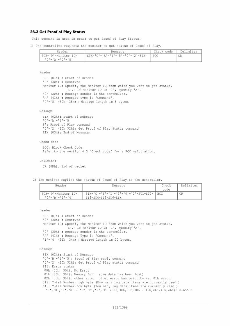
(132/139)
26.3 Get Proof of Play Status This command is used in order to get Proof of Play Status. 1) The controller requests the monitor to get status of Proof of Play.
Header Message Check code Delimiter SOH-'0'-Monitor ID- '0'-'A'-'0'-'8'
STX-'C'-'A'-'1'-'5'-'0'-'2'-ETX BCC CR
Header SOH (01h) : Start of Header '0' (30h) : Reserved Monitor ID: Specify the Monitor ID from which you want to get status.
Ex.) If Monitor ID is '1', specify 'A'. '0' (30h) : Message sender is the controller. 'A' (41h) : Message Type is "Command". '0'-'8' (30h, 38h) : Message length is 8 bytes.
Message STX (02h): Start of Message 'C'-'A'-'1'-'5 6': Proof of Play command '0'-'2' (30h,32h): Get Proof of Play Status command ETX (03h): End of Message
Check code BCC: Block Check Code Refer to the section 4.3 “Check code” for a BCC calculation.
Delimiter CR (0Dh): End of packet
2) The monitor replies the status of Proof of Play to the controller.
Header Message Check code
Delimiter
SOH-'0'-Monitor ID- '0'-'B'-'1'-'4'
STX-'C'-'B'-'1'-'5'-'0'-'2'-ST1-ST2- ST3-ST4-ST5-ST6-ETX
BCC CR
Header SOH (01h) : Start of Header '0' (30h) : Reserved Monitor ID: Specify the Monitor ID from which you want to get status.
Ex.) If Monitor ID is '1', specify 'A'. '0' (30h) : Message sender is the controller. 'A' (41h) : Message Type is "Command". '1'-'4' (31h, 34h) : Message length is 20 bytes.
Message STX (02h): Start of Message 'C'-'B'-'1'-'5': Proof of Play reply command '0'-'2' (30h,32h): Get Proof of Play status command ST1: Error status 00h (30h, 30h): No Error 01h (30h, 30h): Memory full (some date has been lost) 02h (30h, 30h): other error (other error has priority ver 01h error) ST2: Total Number-High byte (How many log data items are currently used.) ST3: Total Number-Low byte (How many log data items are currently used.) '0','0','0','0' - 'F','F','F','F' (30h,30h,30h,30h - 46h,46h,46h,46h): 0-65535
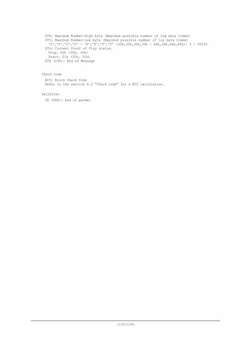
(133/139)
ST4: Maximum Number-High byte (Maximum possible number of log data items) ST5: Maximum Number-Low byte (Maximum possible number of log data items) '0','0','0','0' - 'F','F','F','F' (30h,30h,30h,30h - 46h,46h,46h,46h): 0 - 65535 ST6: Current Proof of Play status.
Stop: 00h (30h, 30h) Start: 01h (30h, 31h) ETX (03h): End of Message
Check code BCC: Block Check Code Refer to the section 4.3 “Check code” for a BCC calculation.
Delimiter CR (0Dh): End of packet
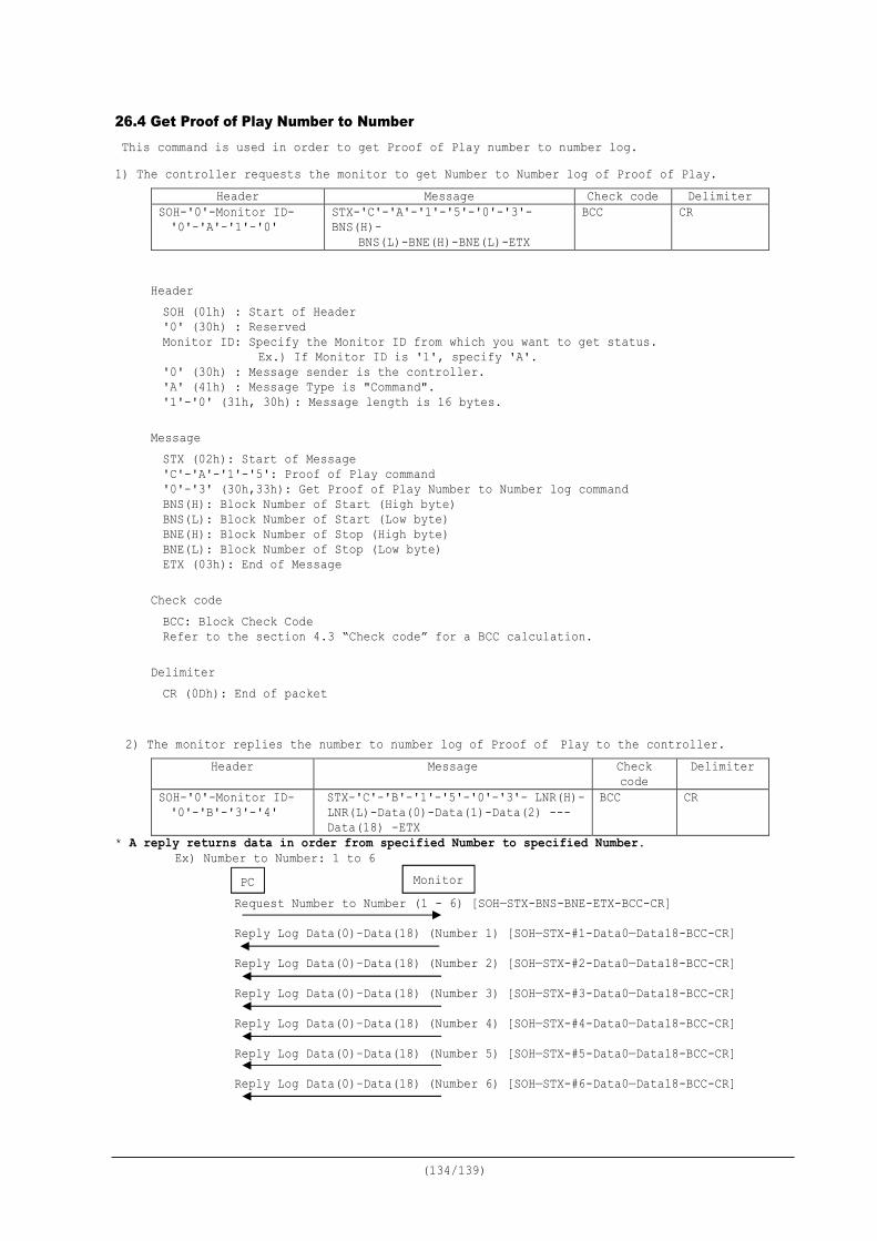
(134/139)
26.4 Get Proof of Play Number to Number This command is used in order to get Proof of Play number to number log. 1) The controller requests the monitor to get Number to Number log of Proof of Play.
Header Message Check code Delimiter SOH-'0'-Monitor ID- '0'-'A'-'1'-'0'
STX-'C'-'A'-'1'-'5'-'0'-'3'-BNS(H)-
BNS(L)-BNE(H)-BNE(L)-ETX
BCC CR
Header SOH (01h) : Start of Header '0' (30h) : Reserved Monitor ID: Specify the Monitor ID from which you want to get status.
Ex.) If Monitor ID is '1', specify 'A'. '0' (30h) : Message sender is the controller. 'A' (41h) : Message Type is "Command". '1'-'0' (31h, 30h) : Message length is 16 bytes.
Message STX (02h): Start of Message 'C'-'A'-'1'-'5': Proof of Play command '0'-'3' (30h,33h): Get Proof of Play Number to Number log command BNS(H): Block Number of Start (High byte) BNS(L): Block Number of Start (Low byte) BNE(H): Block Number of Stop (High byte) BNE(L): Block Number of Stop (Low byte) ETX (03h): End of Message
Check code BCC: Block Check Code Refer to the section 4.3 “Check code” for a BCC calculation.
Delimiter CR (0Dh): End of packet
2) The monitor replies the number to number log of Proof of Play to the controller.
Header Message Check code
Delimiter
SOH-'0'-Monitor ID- '0'-'B'-'3'-'4'
STX-'C'-'B'-'1'-'5'-'0'-'3'- LNR(H)- LNR(L)-Data(0)-Data(1)-Data(2) --- Data(18) -ETX
BCC CR
* A reply returns data in order from specified Number to specified Number. Ex) Number to Number: 1 to 6 Request Number to Number (1 - 6) [SOH—STX-BNS-BNE-ETX-BCC-CR] Reply Log Data(0)–Data(18) (Number 1) [SOH—STX-#1-Data0—Data18-BCC-CR] Reply Log Data(0)–Data(18) (Number 2) [SOH—STX-#2-Data0—Data18-BCC-CR] Reply Log Data(0)–Data(18) (Number 3) [SOH—STX-#3-Data0—Data18-BCC-CR] Reply Log Data(0)–Data(18) (Number 4) [SOH—STX-#4-Data0—Data18-BCC-CR] Reply Log Data(0)–Data(18) (Number 5) [SOH—STX-#5-Data0—Data18-BCC-CR] Reply Log Data(0)–Data(18) (Number 6) [SOH—STX-#6-Data0—Data18-BCC-CR]
PC Monitor
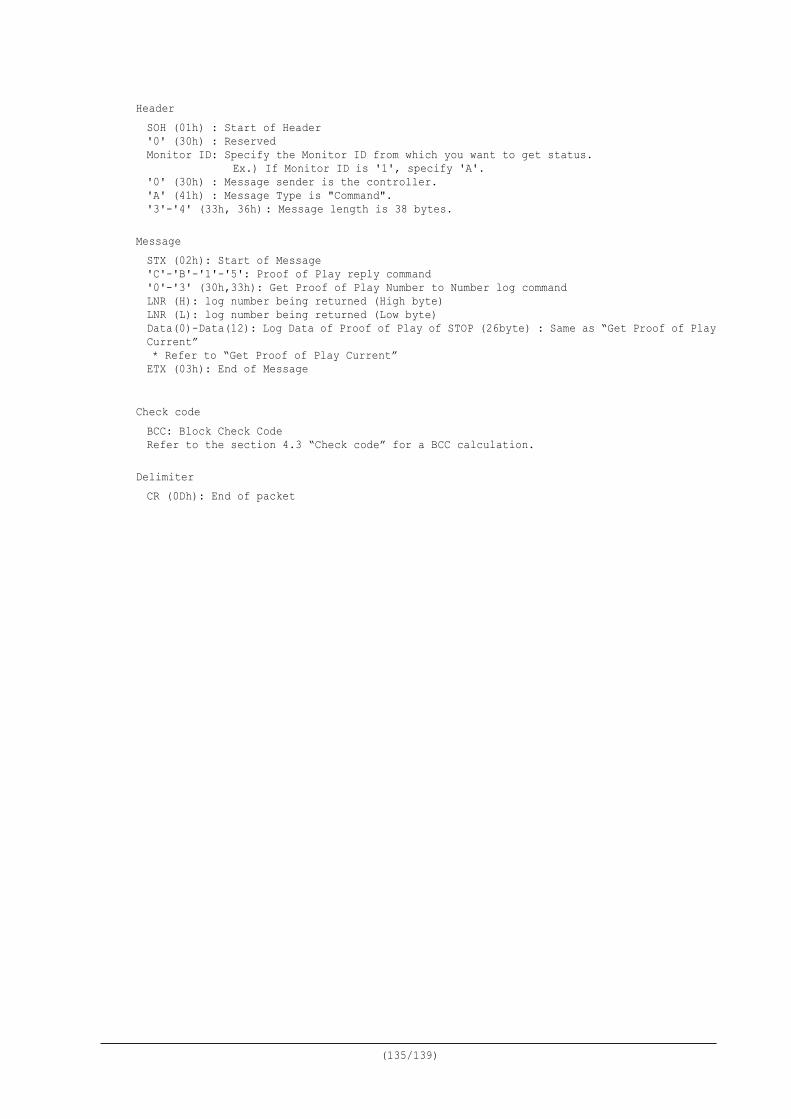
(135/139)
Header SOH (01h) : Start of Header '0' (30h) : Reserved Monitor ID: Specify the Monitor ID from which you want to get status.
Ex.) If Monitor ID is '1', specify 'A'. '0' (30h) : Message sender is the controller. 'A' (41h) : Message Type is "Command". '3'-'4' (33h, 36h) : Message length is 38 bytes.
Message STX (02h): Start of Message 'C'-'B'-'1'-'5': Proof of Play reply command '0'-'3' (30h,33h): Get Proof of Play Number to Number log command LNR (H): log number being returned (High byte) LNR (L): log number being returned (Low byte) Data(0)-Data(12): Log Data of Proof of Play of STOP (26byte) : Same as “Get Proof of Play Current” * Refer to “Get Proof of Play Current” ETX (03h): End of Message
Check code BCC: Block Check Code Refer to the section 4.3 “Check code” for a BCC calculation.
Delimiter CR (0Dh): End of packet
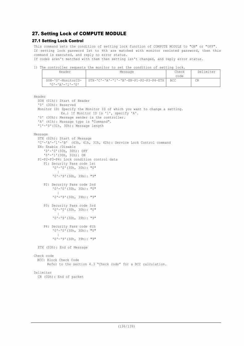
(136/139)
27. Setting Lock of COMPUTE MODULE 27.1 Setting Lock Control This command sets the condition of setting lock function of COMPUTE MODULE to "ON" or "OFF". If setting lock password 1st to 4th are matched with monitor resisted password, then this command is executed, and reply no error status. If codes aren't matched with them then setting isn't changed, and reply error status. 1) The controller requests the monitor to set the condition of setting lock.
Header Message Check code
Delimiter
SOH-'0'-MonitorID- '0'-'A'-'1'-'0'
STX-'C'-'A'-'1'-'B'-EN-P1-P2-P3-P4-ETX BCC CR
Header
SOH (01h): Start of Header '0' (30h): Reserved Monitor ID: Specify the Monitor ID of which you want to change a setting.
Ex.) If Monitor ID is '1', specify 'A'. '0' (30h): Message sender is the controller. 'A' (41h): Message type is "Command". '1'-'0'(31h, 30h): Message length
Message STX (02h): Start of Message 'C'-'A'-'1'-'B' (43h, 41h, 31h, 42h): Service Lock Control command EN: Enable /Disable
'0'-'0'(30h, 30h): OFF '0'-'1'(30h, 31h): ON
P1-P2-P3-P4: Lock condition control data P1: Security Pass code 1st
'0'-'0'(30h, 30h): "0" | '0'-'9'(30h, 39h): "9"
P2: Security Pass code 2nd
'0'-'0'(30h, 30h): "0" | '0'-'9'(30h, 39h): "9"
P3: Security Pass code 3rd
'0'-'0'(30h, 30h): "0" | '0'-'9'(30h, 39h): "9"
P4: Security Pass code 4th
'0'-'0'(30h, 30h): "0" | '0'-'9'(30h, 39h): "9"
ETX (03h): End of Message
Check code BCC: Block Check Code Refer to the section 4.3 “Check code” for a BCC calculation.
Delimiter
CR (0Dh): End of packet
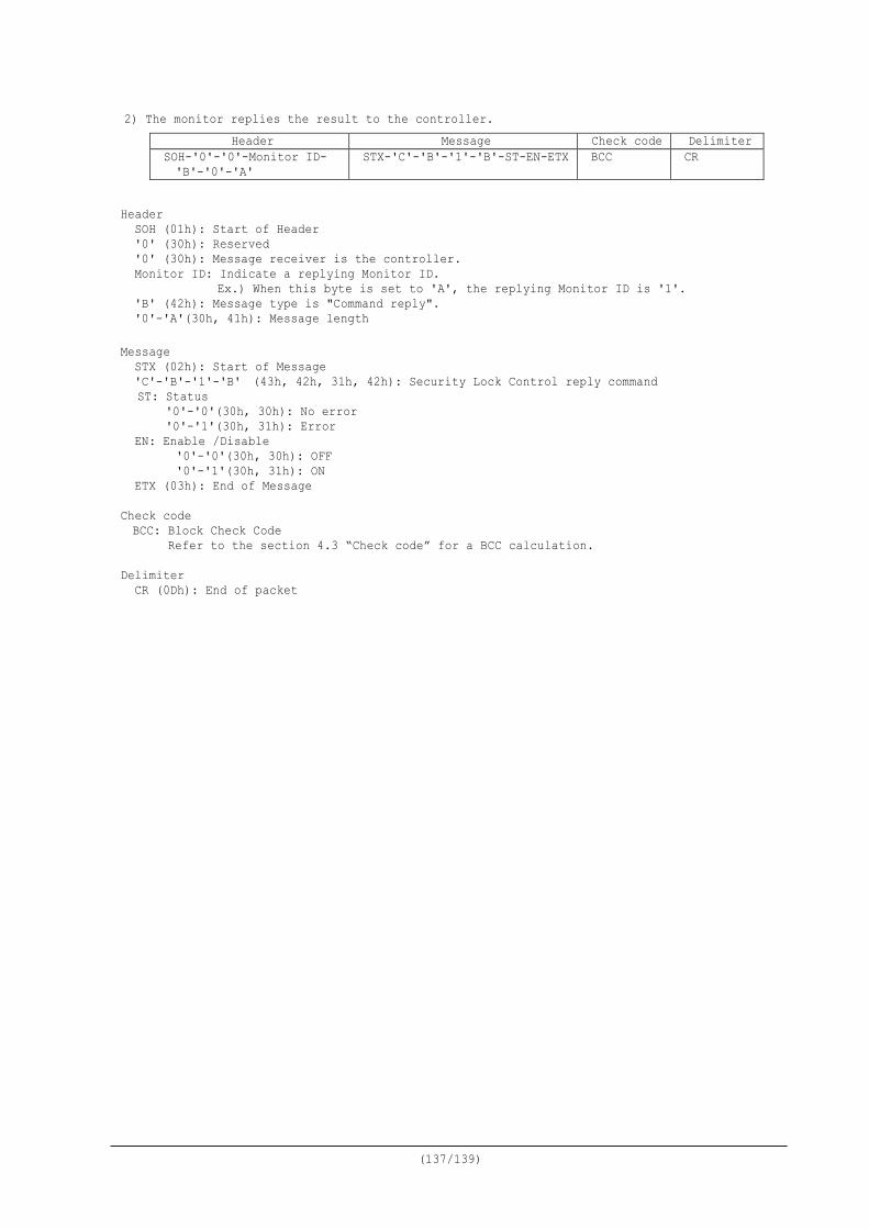
(137/139)
2) The monitor replies the result to the controller. Header Message Check code Delimiter
SOH-'0'-'0'-Monitor ID- 'B'-'0'-'A'
STX-'C'-'B'-'1'-'B'-ST-EN-ETX BCC CR
Header
SOH (01h): Start of Header '0' (30h): Reserved '0' (30h): Message receiver is the controller. Monitor ID: Indicate a replying Monitor ID.
Ex.) When this byte is set to 'A', the replying Monitor ID is '1'. 'B' (42h): Message type is "Command reply". '0'-'A'(30h, 41h): Message length
Message STX (02h): Start of Message 'C'-'B'-'1'-'B' (43h, 42h, 31h, 42h): Security Lock Control reply command ST: Status
'0'-'0'(30h, 30h): No error '0'-'1'(30h, 31h): Error
EN: Enable /Disable '0'-'0'(30h, 30h): OFF '0'-'1'(30h, 31h): ON
ETX (03h): End of Message
Check code BCC: Block Check Code Refer to the section 4.3 “Check code” for a BCC calculation.
Delimiter
CR (0Dh): End of packet
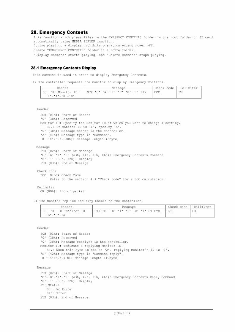
(138/139)
28. Emergency Contents This function which plays files in the EMRGENCY CONTENTS folder in the root folder on SD card automatically using MEDIA PLAYER function. During playing, a display prohibits operation except power off. Create “EMERGENCY CONTENTS” folder in a route folder. "Display command" starts playing, and "Delete command" stops playing.
28.1 Emergency Contents Display This command is used in order to display Emergency Contents. 1) The controller requests the monitor to display Emergency Contents.
Header Message Check code Delimiter SOH-'0'-Monitor ID- '0'-'A'-'0'-'8'
STX-'C'-'A'-'1'-'F'-'0'-'1'-ETX BCC CR
Header SOH (01h): Start of Header '0' (30h): Reserved Monitor ID: Specify the Monitor ID of which you want to change a setting.
Ex.) If Monitor ID is '1', specify 'A'. '0' (30h): Message sender is the controller. 'A' (41h): Message type is "Command". '0'-'8'(30h, 38h): Message length (8byte)
Message STX (02h): Start of Message 'C'-'A'-'1'-'F' (43h, 41h, 31h, 46h): Emergency Contents Command '0'-'1' (30h, 32h): Display ETX (03h): End of Message
Check code BCC: Block Check Code Refer to the section 4.3 “Check code” for a BCC calculation.
Delimiter CR (0Dh): End of packet
2) The monitor replies Security Enable to the controller.
Header Message Check code Delimiter SOH-'0'-'0'-Monitor ID- 'B'-'0'-'A'
STX-'C'-'B'-'1'-'F'-'0'-'1'-ST-ETX BCC CR
Header SOH (01h): Start of Header '0' (30h): Reserved '0' (30h): Message receiver is the controller. Monitor ID: Indicate a replying Monitor ID.
Ex.) When this byte is set to ‘A’, replying monitor’s ID is ‘1’. 'B' (42h): Message type is "Command reply". '0'-'A'(30h,41h): Message length (10byte)
Message STX (02h): Start of Message 'C'-'B'-'1'-'F' (43h, 42h, 31h, 46h): Emergency Contents Reply Command '0'-'1' (30h, 32h): Display ST: Status 00h: No Error 01h: Error ETX (03h): End of Message

(139/139)
Check code BCC: Block Check Code
Refer to the section 4.3 “Check code” for a BCC calculation. Delimiter CR (0Dh): End of packet
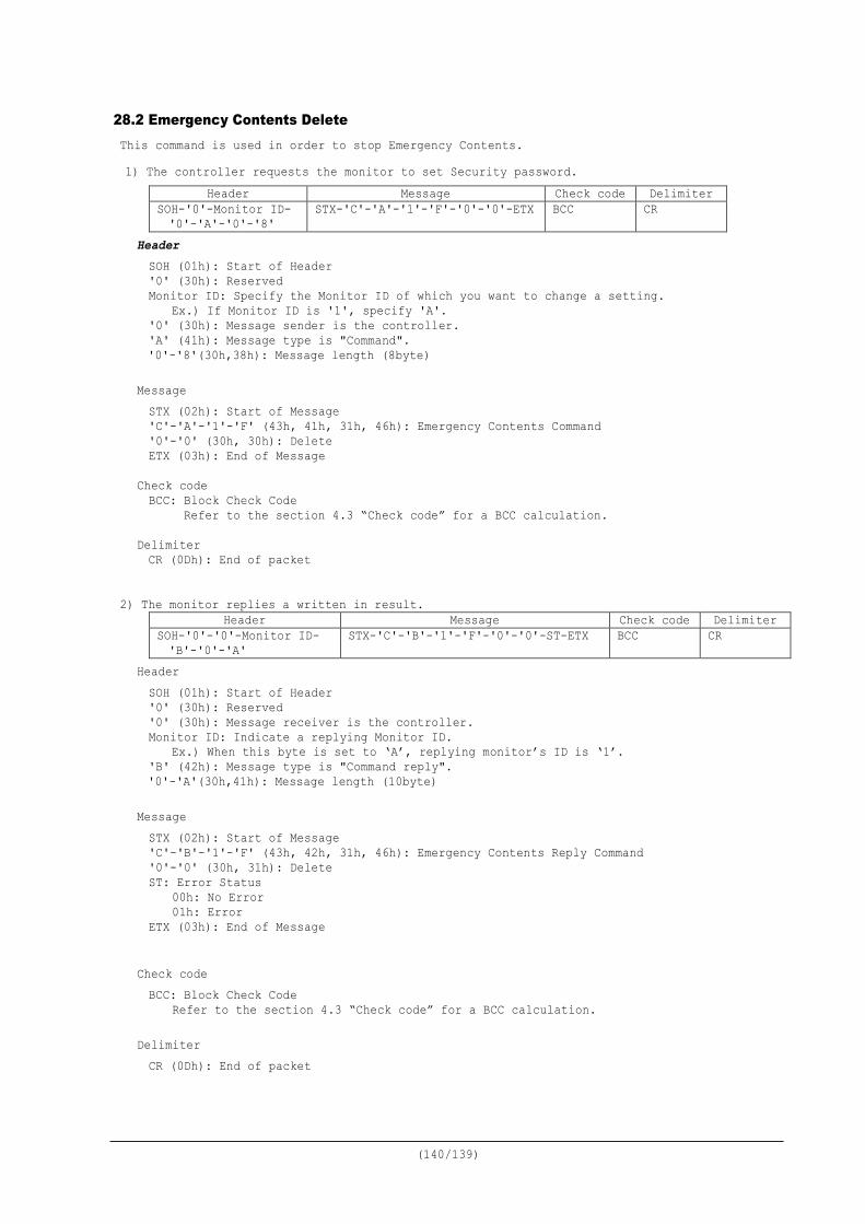
(140/139)
28.2 Emergency Contents Delete This command is used in order to stop Emergency Contents. 1) The controller requests the monitor to set Security password.
Header Message Check code Delimiter SOH-'0'-Monitor ID- '0'-'A'-'0'-'8'
STX-'C'-'A'-'1'-'F'-'0'-'0'-ETX BCC CR
Header SOH (01h): Start of Header '0' (30h): Reserved Monitor ID: Specify the Monitor ID of which you want to change a setting.
Ex.) If Monitor ID is '1', specify 'A'. '0' (30h): Message sender is the controller. 'A' (41h): Message type is "Command". '0'-'8'(30h,38h): Message length (8byte)
Message STX (02h): Start of Message 'C'-'A'-'1'-'F' (43h, 41h, 31h, 46h): Emergency Contents Command '0'-'0' (30h, 30h): Delete ETX (03h): End of Message
Check code BCC: Block Check Code Refer to the section 4.3 “Check code” for a BCC calculation.
Delimiter CR (0Dh): End of packet
2) The monitor replies a written in result. Header Message Check code Delimiter
SOH-'0'-'0'-Monitor ID- 'B'-'0'-'A'
STX-'C'-'B'-'1'-'F'-'0'-'0'-ST-ETX BCC CR
Header SOH (01h): Start of Header '0' (30h): Reserved '0' (30h): Message receiver is the controller. Monitor ID: Indicate a replying Monitor ID.
Ex.) When this byte is set to ‘A’, replying monitor’s ID is ‘1’. 'B' (42h): Message type is "Command reply". '0'-'A'(30h,41h): Message length (10byte)
Message STX (02h): Start of Message 'C'-'B'-'1'-'F' (43h, 42h, 31h, 46h): Emergency Contents Reply Command '0'-'0' (30h, 31h): Delete ST: Error Status 00h: No Error 01h: Error ETX (03h): End of Message
Check code BCC: Block Check Code
Refer to the section 4.3 “Check code” for a BCC calculation. Delimiter CR (0Dh): End of packet

(141/139)
All data are subject to change without notice.
(March 2, 2018)
Copyright 2004-2018 NEC Display Solutions, Ltd. All Right Reserved This document provides the technical information for users. NEC Display Solutions, Ltd. reserves the right to change or modify the information contained herein without notice. NEC Display Solutions, Ltd. makes no warranty for the use of its products and bears no responsibility for any errors or omissions which may appear in this document.
Recommended