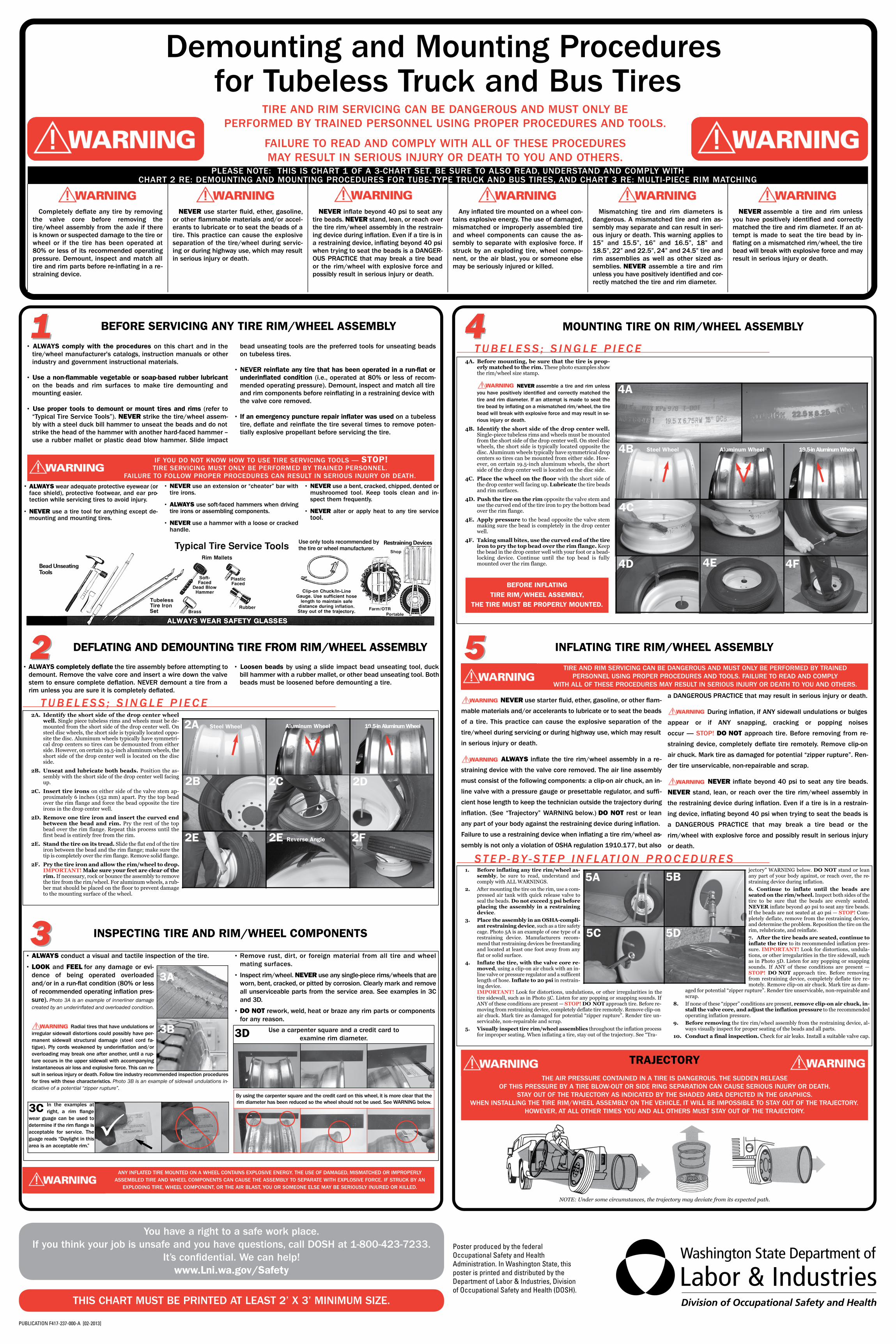
4A. Before mounting, be sure that the tire is prop-erly matched to the rim. These photo examples showthe rim/wheel size stamp.
NEVER assemble a tire and rim unlessyou have positively identi�ed and correctly matched thetire and rim diameter. If an attempt is made to seat thetire bead by in�ating on a mismatched rim/wheel, the tirebead will break with explosive force and may result in se-rious injury or death.
4B. Identify the short side of the drop center well.Single-piece tubeless rims and wheels must be mountedfrom the short side of the drop center well. On steel discwheels, the short side is typically located opposite thedisc. Aluminum wheels typically have symmetrical dropcenters so tires can be mounted from either side. How-ever, on certain 19.5-inch aluminum wheels, the shortside of the drop center well is located on the disc side.
4C. Place the wheel on the floor with the short side ofthe drop center well facing up. Lubricate the tire beadsand rim surfaces.
4D. Push the tire on the rim opposite the valve stem anduse the curved end of the tire iron to pry the bottom beadover the rim flange.
4E. Apply pressure to the bead opposite the valve stemmaking sure the bead is completely in the drop centerwell.
4F. Taking small bites, use the curved end of the tireiron to pry the top bead over the rim flange. Keepthe bead in the drop center well with your foot or a bead-locking device. Continue until the top bead is fullymounted over the rim flange.
MOUNTING TIRE ON RIM/WHEEL ASSEMBLY
Completely de�ate any tire by removingthe valve core before removing thetire/wheel assembly from the axle if thereis known or suspected damage to the tire orwheel or if the tire has been operated at80% or less of its recommended operatingpressure. Demount, inspect and match alltire and rim parts before re-in�ating in a re-straining device.
NEVER use starter �uid, ether, gasoline,or other �ammable materials and/or accel-erants to lubricate or to seat the beads of atire. This practice can cause the explosiveseparation of the tire/wheel during servic-ing or during highway use, which may resultin serious injury or death.
NEVER in�ate beyond 40 psi to seat anytire beads. NEVER stand, lean, or reach overthe tire rim/wheel assembly in the restrain-ing device during in�ation. Even if a tire is ina restraining device, in�ating beyond 40 psiwhen trying to seat the beads is a DANGER-OUS PRACTICE that may break a tire beador the rim/wheel with explosive force andpossibly result in serious injury or death.
Any in�ated tire mounted on a wheel con-tains explosive energy. The use of damaged,mismatched or improperly assembled tireand wheel components can cause the as-sembly to separate with explosive force. Ifstruck by an exploding tire, wheel compo-nent, or the air blast, you or someone elsemay be seriously injured or killed.
Mismatching tire and rim diameters isdangerous. A mismatched tire and rim as-sembly may separate and can result in seri-ous injury or death. This warning applies to15” and 15.5”, 16” and 16.5”, 18” and18.5”, 22” and 22.5”, 24” and 24.5” tire andrim assemblies as well as other sized as-semblies. NEVER assemble a tire and rimunless you have positively identi�ed and cor-rectly matched the tire and rim diameter.
NEVER assemble a tire and rim unlessyou have positively identi�ed and correctlymatched the tire and rim diameter. If an at-tempt is made to seat the tire bead by in-�ating on a mismatched rim/wheel, the tirebead will break with explosive force and mayresult in serious injury or death.
DEFLATING AND DEMOUNTING TIRE FROM RIM/WHEEL ASSEMBLY
2A. Identify the short side of the drop center wheelwell. Single piece tubeless rims and wheels must be de-mounted from the short side of the drop center well. Onsteel disc wheels, the short side is typically located oppo-site the disc. Aluminum wheels typically have symmetri-cal drop centers so tires can be demounted from eitherside. However, on certain 19.5-inch aluminum wheels, theshort side of the drop center well is located on the discside.
2B. Unseat and lubricate both beads. Position the as-sembly with the short side of the drop center well facingup.
2C. Insert tire irons on either side of the valve stem ap-proximately 6 inches (152 mm) apart. Pry the top beadover the rim flange and force the bead opposite the tireirons in the drop center well.
2D. Remove one tire iron and insert the curved endbetween the bead and rim. Pry the rest of the topbead over the rim flange. Repeat this process until thefirst bead is entirely free from the rim.
2E. Stand the tire on its tread. Slide the flat end of the tireiron between the bead and the rim flange; make sure thetip is completely over the rim flange. Remove solid flange.
2F. Pry the tire iron and allow the rim/wheel to drop.IMPORTANT! Make sure your feet are clear of therim. If necessary, rock or bounce the assembly to removethe tire from the rim/wheel. For aluminum wheels, a rub-ber mat should be placed on the floor to prevent damageto the mounting surface of the wheel.
TUBELESS ; S INGLE P I ECE
• ALWAYS completely deflate the tire assembly before attempting todemount. Remove the valve core and insert a wire down the valvestem to ensure complete de�ation. NEVER demount a tire from arim unless you are sure it is completely de�ated.
• Loosen beads by using a slide impact bead unseating tool, duckbill hammer with a rubber mallet, or other bead unseating tool. Bothbeads must be loosened before demounting a tire.
TUBELESS ; S INGLE P I ECE
PLEASE NOTE: THIS IS CHART 1 OF A 3-CHART SET. BE SURE TO ALSO READ, UNDERSTAND AND COMPLY WITH CHART 2 RE: DEMOUNTING AND MOUNTING PROCEDURES FOR TUBE-TYPE TRUCK AND BUS TIRES, AND CHART 3 RE: MULTI-PIECE RIM MATCHING
IF YOU DO NOT KNOW HOW TO USE TIRE SERVICING TOOLS — STOP!TIRE SERVICING MUST ONLY BE PERFORMED BY TRAINED PERSONNEL.
FAILURE TO FOLLOW PROPER PROCEDURES CAN RESULT IN SERIOUS INJURY OR DEATH.
BEFORE SERVICING ANY TIRE RIM/WHEEL ASSEMBLY
• ALWAYS comply with the procedures on this chart and in thetire/wheel manufacturer's catalogs, instruction manuals or otherindustry and government instructional materials.
• Use a non-flammable vegetable or soap-based rubber lubricanton the beads and rim surfaces to make tire demounting andmounting easier.
• Use proper tools to demount or mount tires and rims (refer to“Typical Tire Service Tools”). NEVER strike the tire/wheel assem-bly with a steel duck bill hammer to unseat the beads and do notstrike the head of the hammer with another hard-faced hammer –use a rubber mallet or plastic dead blow hammer. Slide impact
bead unseating tools are the preferred tools for unseating beadson tubeless tires.
• NEVER reinflate any tire that has been operated in a run-flat orunderinflated condition (i.e., operated at 80% or less of recom-mended operating pressure). Demount, inspect and match all tireand rim components before rein�ating in a restraining device withthe valve core removed.
• If an emergency puncture repair inflater was used on a tubelesstire, de�ate and rein�ate the tire several times to remove poten-tially explosive propellant before servicing the tire.
• ALWAYS wear adequate protective eyewear (orface shield), protective footwear, and ear pro-tection while servicing tires to avoid injury.
• NEVER use a tire tool for anything except de-mounting and mounting tires.
• NEVER use an extension or “cheater” bar withtire irons.
• ALWAYS use soft-faced hammers when drivingtire irons or assembling components.
• NEVER use a hammer with a loose or crackedhandle.
• NEVER use a bent, cracked, chipped, dented ormushroomed tool. Keep tools clean and in-spect them frequently.
• NEVER alter or apply heat to any tire servicetool.
2B 2D2C
2E 2E Reverse Angle 2F
• ALWAYS conduct a visual and tactile inspection of the tire.
• LOOK and FEEL for any damage or evi-dence of being operated overloadedand/or in a run-�at condition (80% or lessof recommended operating in�ation pres-sure). Photo 3A is an example of innerliner damagecreated by an underinflated and overloaded condition.
Radial tires that have undulations orirregular sidewall distortions could possibly have per-manent sidewall structural damage (steel cord fa-tigue). Ply cords weakened by underin�ation and/oroverloading may break one after another, until a rup-ture occurs in the upper sidewall with accompanyinginstantaneous air loss and explosive force. This can re-sult in serious injury or death. Follow tire industry recommended inspection proceduresfor tires with these characteristics. Photo 3B is an example of sidewall undulations in-dicative of a potential “zipper rupture”.
• Remove rust, dirt, or foreign material from all tire and wheelmating surfaces.
• Inspect rim/wheel. NEVER use any single-piece rims/wheels that areworn, bent, cracked, or pitted by corrosion. Clearly mark and removeall unserviceable parts from the service area. See examples in 3Cand 3D.
• DO NOT rework, weld, heat or braze any rim parts or componentsfor any reason.
INSPECTING TIRE AND RIM/WHEEL COMPONENTS
ANY INFLATED TIRE MOUNTED ON A WHEEL CONTAINS EXPLOSIVE ENERGY. THE USE OF DAMAGED, MISMATCHED OR IMPROPERLY ASSEMBLED TIRE AND WHEEL COMPONENTS CAN CAUSE THE ASSEMBLY TO SEPARATE WITH EXPLOSIVE FORCE. IF STRUCK BY AN
EXPLODING TIRE, WHEEL COMPONENT, OR THE AIR BLAST, YOU OR SOMEONE ELSE MAY BE SERIOUSLY INJURED OR KILLED.
4B Aluminum WheelSteel Wheel 19.5-in Aluminum Wheel
4C
4D 4E 4F
BEFORE INFLATING TIRE RIM/WHEEL ASSEMBLY,
THE TIRE MUST BE PROPERLY MOUNTED.
1. Before inflating any tire rim/wheel as-sembly, be sure to read, understand andcomply with ALL WARNINGS.
2. After mounting the tire on the rim, use a com-pressed air tank with quick release valve toseal the beads. Do not exceed 5 psi beforeplacing the assembly in a restrainingdevice.
3. Place the assembly in an OSHA-compli-ant restraining device, such as a tire safetycage. Photo 5A is an example of one type of arestraining device. Manufacturers recom-mend that restraining devices be freestandingand located at least one foot away from anyflat or solid surface.
4. Inflate the tire, with the valve core re-moved, using a clip-on air chuck with an in-line valve or pressure regulator and a sufficentlength of hose. Inflate to 20 psi in restrain-ing device. IMPORTANT! Look for distortions, undulations, or other irregularities in thetire sidewall, such as in Photo 5C. Listen for any popping or snapping sounds. IfANY of these conditions are present — STOP! DO NOT approach tire. Before re-moving from restraining device, completely deflate tire remotely. Remove clip-onair chuck. Mark tire as damaged for potential “zipper rupture”. Render tire un-servicable, non-repairable and scrap.
5. Visually inspect tire rim/wheel assemblies throughout the inflation processfor improper seating. When inflating a tire, stay out of the trajectory. See “Tra-
jectory” WARNING below. DO NOT stand or leanany part of your body against, or reach over, the re-straining device during inflation.
6. Continue to inflate until the beads areseated on the rim/wheel. Inspect both sides of thetire to be sure that the beads are evenly seated.NEVER inflate beyond 40 psi to seat any tire beads.If the beads are not seated at 40 psi — STOP! Com-pletely deflate, remove from the restraining device,and determine the problem. Reposition the tire on therim, relubricate, and reinflate.
7. After the tire beads are seated, continue toinflate the tire to its recommended inflation pres-sure. IMPORTANT! Look for distortions, undula-tions, or other irregularities in the tire sidewall, suchas in Photo 5D. Listen for any popping or snappingsounds. If ANY of these conditions are present —STOP! DO NOT approach tire. Before removingfrom restraining device, completely deflate tire re-motely. Remove clip-on air chuck. Mark tire as dam-
aged for potential “zipper rupture”. Render tire unservicable, non-repairable andscrap.
8. If none of these “zipper” conditions are present, remove clip-on air chuck, in-stall the valve core, and adjust the inflation pressure to the recommendedoperating inflation pressure.
9. Before removing the tire rim/wheel assembly from the restraining device, al-ways visually inspect for proper seating of the beads and all parts.
10. Conduct a final inspection. Check for air leaks. Install a suitable valve cap.
TIRE AND RIM SERVICING CAN BE DANGEROUS AND MUST ONLY BE PERFORMED BY TRAINED PERSONNEL USING PROPER PROCEDURES AND TOOLS. FAILURE TO READ AND COMPLY
WITH ALL OF THESE PROCEDURES MAY RESULT IN SERIOUS INJURY OR DEATH TO YOU AND OTHERS.
TRAJECTORYTHE AIR PRESSURE CONTAINED IN A TIRE IS DANGEROUS. THE SUDDEN RELEASE
OF THIS PRESSURE BY A TIRE BLOW-OUT OR SIDE RING SEPARATION CAN CAUSE SERIOUS INJURY OR DEATH. STAY OUT OF THE TRAJECTORY AS INDICATED BY THE SHADED AREA DEPICTED IN THE GRAPHICS.
WHEN INSTALLING THE TIRE RIM/WHEEL ASSEMBLY ON THE VEHICLE, IT WILL BE IMPOSSIBLE TO STAY OUT OF THE TRAJECTORY. HOWEVER, AT ALL OTHER TIMES YOU AND ALL OTHERS MUST STAY OUT OF THE TRAJECTORY.
NEVER use starter �uid, ether, gasoline, or other �am-
mable materials and/or accelerants to lubricate or to seat the beads
of a tire. This practice can cause the explosive separation of the
tire/wheel during servicing or during highway use, which may result
in serious injury or death.
ALWAYS in�ate the tire rim/wheel assembly in a re-
straining device with the valve core removed. The air line assembly
must consist of the following components: a clip-on air chuck, an in-
line valve with a pressure gauge or presettable regulator, and suf�-
cient hose length to keep the technician outside the trajectory during
in�ation. (See “Trajectory” WARNING below.) DO NOT rest or lean
any part of your body against the restraining device during in�ation.
Failure to use a restraining device when in�ating a tire rim/wheel as-
sembly is not only a violation of OSHA regulation 1910.177, but also
a DANGEROUS PRACTICE that may result in serious injury or death.
During in�ation, if ANY sidewall undulations or bulges
appear or if ANY snapping, cracking or popping noises
occur — STOP! DO NOT approach tire. Before removing from re-
straining device, completely de�ate tire remotely. Remove clip-on
air chuck. Mark tire as damaged for potential “zipper rupture”. Ren-
der tire unservicable, non-repairable and scrap.
NEVER in�ate beyond 40 psi to seat any tire beads.
NEVER stand, lean, or reach over the tire rim/wheel assembly in
the restraining device during in�ation. Even if a tire is in a restrain-
ing device, in�ating beyond 40 psi when trying to seat the beads is
a DANGEROUS PRACTICE that may break a tire bead or the
rim/wheel with explosive force and possibly result in serious injury
or death.
STEP -BY - S TEP INFLAT ION PROCEDURES
NOTE: Under some circumstances, the trajectory may deviate from its expected path.
Use a carpenter square and a credit card to examine rim diameter.
By using the carpenter square and the credit card on this wheel, it is more clear that therim diameter has been reduced so the wheel should not be used. See WARNING below.
3A
3B
In the examples atright, a rim �ange
wear guage can be used todetermine if the rim �ange isacceptable for service. Theguage reads “Daylight in thisarea is an acceptable rim.”
3C
3D
5A 5B
5C 5D
2A Steel Wheel Aluminum Wheel 19.5-in Aluminum Wheel
4A
INFLATING TIRE RIM/WHEEL ASSEMBLY
www.osha.gov • (800) 321-OSHA (6742) • TTY (877) 889-5627
You have a right to a safe workplace.If you think your job is unsafe and you have questions, call OSHA.
It’s con�dential. We can help!
OS
HA
340
1 10
R-1
1
THIS CHART MUST BE PRINTED ATLEAST 2’ x 3’ MINIMUM SIZE.
1
Demounting and Mounting Procedures for Tubeless Truck and Bus Tires
1 4
3
4
3
22 55
TIRE AND RIM SERVICING CAN BE DANGEROUS AND MUST ONLY BE PERFORMED BY TRAINED PERSONNEL USING PROPER PROCEDURES AND TOOLS.
FAILURE TO READ AND COMPLY WITH ALL OF THESE PROCEDURES MAY RESULT IN SERIOUS INJURY OR DEATH TO YOU AND OTHERS.
Poster produced by the federal Occupational Safety and Health Administration. In Washington State, this poster is printed and distributed by the Department of Labor & Industries, Division of Occupational Safety and Health (DOSH).
You have a right to a safe work place. If you think your job is unsafe and you have questions, call DOSH at 1-800-423-7233.
It’s confidential. We can help!www.Lni.wa.gov/Safety
THIS CHART MUST BE PRINTED AT LEAST 2’ X 3’ MINIMUM SIZE.
PUBLICATION F417-237-000-A [02-2013]
Recommended