Failure and Replacement of Ammonia Converter Baskets
and Application of AmoMax Catalyst
Pressure drop across Incitec Pivot’s ammonia converter baskets significantly increased over a 5-month pe-
riod in 2006. This pressure drop resulted in a significant loss in ammonia production. In addition, the 35-
year-old pressure vessels had developed cracks around the nozzles. Because of these two problems, Incitec
Pivot Ltd (IPL) decided to replace the converter baskets, the catalyst and the pressure shells during their
2007 turnaround. After considering the options that were available, IPL decided to replace the old baskets
with Casale’s new slotted plate design. To maximize production from the new baskets and internals, Amo-
Max ammonia synthesis catalyst was chosen.
This project highlights the need to have plans in place to mitigate any potential risks that could impact plant
reliability with some pro-active approaches taken during replacement of the pressure vessels and axial-
radial baskets. The paper also describes in detail the systematic root cause analysis of the failure, safety
and design reviews of the new baskets, hazop studies, safety measures taken while unloading the old catalyst
and dense loading the new catalyst, catalyst reduction, performance tests etc.
David Pearce and Venkat Pattabathula
Incitec Pivot Ltd, Brisbane, Australia
Suresh Bhatia
Division of Chemical Engineering
The University of Queensland, Brisbane, Australia
Massimo Iob
Ammonia Casale, Lugano, Swtizerland
and
Jim Richardson
Sud-Chemie, South East Asia, Singapore
Introduction
Incited Pivot operates an ammonia plant designed
by J.F. Pritchard that originally produced 600
mtpd. Many upgrades have been made since the
original commissioning in the late 1960’s, which
have increased the operating rate to more than 800
mtpd. Ammonia Casale revamped the second and
third ammonia converter bottles of each bank in
1989, while a new add-on converter downstream
of the original converter bottles was installed in a
1997 upgrade. Unique features of this plant are a
low pressure front-end operating at 450 psig (32
bar), a high pressure synthesis loop operating at
2600 psig (182 bar), a medium pressure steam
system operating at 400 psig (38 bar) and 750oF
(400oC), a closed loop refrigeration system and a
Jet engine that drives a reaction turbine which in
turn drives the synthesis gas compressor.
267 AMMONIA TECHNICAL MANUAL2008
The site has also a urea plant designed by Vulcan
Cincinnati, USA. The urea plant has been up-
graded over the years to about 850 mtpd. The
plant is located at Gibson Island (GI) in the East-
ern suburbs of Brisbane on the East Coast of Aus-
tralia.
Synthesis loop configuration
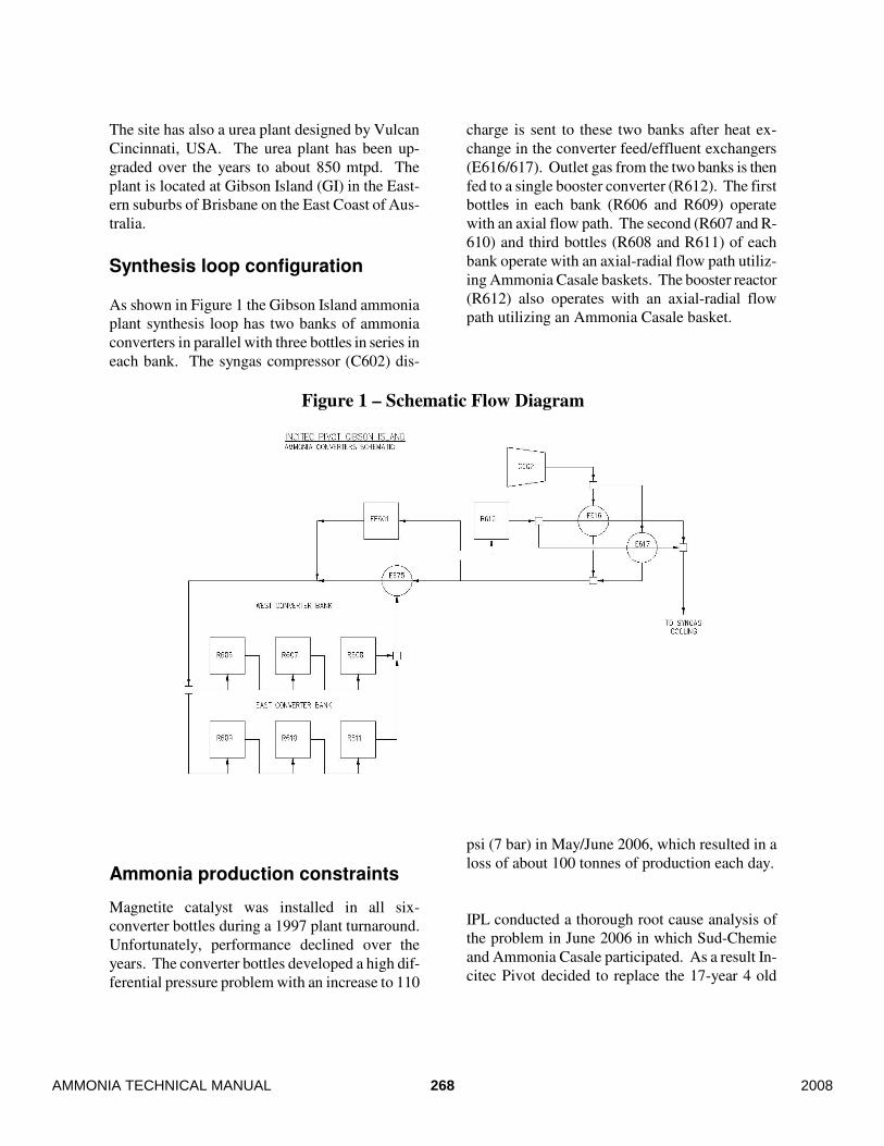
As shown in Figure 1 the Gibson Island ammonia
plant synthesis loop has two banks of ammonia
converters in parallel with three bottles in series in
each bank. The syngas compressor (C602) dis-
charge is sent to these two banks after heat ex-
change in the converter feed/effluent exchangers
(E616/617). Outlet gas from the two banks is then
fed to a single booster converter (R612). The first
bottles in each bank (R606 and R609) operate
with an axial flow path. The second (R607 and R-
610) and third bottles (R608 and R611) of each
bank operate with an axial-radial flow path utiliz-
ing Ammonia Casale baskets. The booster reactor
(R612) also operates with an axial-radial flow
path utilizing an Ammonia Casale basket.
Figure 1 – Schematic Flow Diagram
Ammonia production constraints
Magnetite catalyst was installed in all six-
converter bottles during a 1997 plant turnaround.
Unfortunately, performance declined over the
years. The converter bottles developed a high dif-
ferential pressure problem with an increase to 110
psi (7 bar) in May/June 2006, which resulted in a
loss of about 100 tonnes of production each day.
IPL conducted a thorough root cause analysis of
the problem in June 2006 in which Sud-Chemie
and Ammonia Casale participated. As a result In-
citec Pivot decided to replace the 17-year 4 old
268AMMONIA TECHNICAL MANUAL 2008
baskets in R607, 608, 610 & 611. It was also de-
cided to replace the entire magnetite catalyst with
new catalyst in all 6-converter bottles (excluding
the booster reactor).
A presentation was made by Sud-Chemie South
East Asia to the Incitec Pivot team in early 2006
on the potential application of AmoMax catalyst
in all 6-converter bottles. Sud-Chemie cited a
number of references including that of Agrolinz in
Austria and Koch N2, Fort Dodge Iowa, USA. In-
citec Pivot contacted these two plants and re-
quested information on the catalyst performance.
Both plants provided very positive feedback about
the success of AmoMax catalyst in their plants.
Incitec Pivot had also observed cracks on the noz-
zles of the original carbon steel pressure shells,
which were repaired in a backend outage in 2005.
Hence, IPL decided to replace all 6-pressure shells
in 2007 plant turnaround. Unfortunately, the high-
pressure drop across converter banks was experi-
enced after placing the order for the new pressure
shells. If the pressure drop had occurred before
the order was placed, IPL would have considered
a single ammonia converter with indirect cooling
of the catalyst beds.
Study by the University of Queensland (Uniquest)
Incitec Pivot awarded a project to The University
of Queensland to test AmoMax catalyst. Sud-
Chemie provided a sample of AmoMax 10H (pre-
reduced), and IPL collected two other commer-
cially available magnetite catalyst samples for
testing. The objective of the Uniquest project was
to investigate and compare the structure, deactiva-
tion, and strength of the Sud-Chemie AmoMax-10
wustite catalyst sample with the two-magnetite
catalyst samples. The study was expected to yield
insight into the differences between the catalysts
related to reactivity, deactivation and catalyst life.
The following studies were done to investigate
these variables:
(i) Testing of the strength of the original and
pre-reduced wustite and magnetite catalyst
(ii) Investigations of the pore structure for the
pre-reduced catalyst
(iii) Microscopic examinations using scanning
and transmission electron microscopy
(iv) Carbon dioxide and moisture adsorption
isotherms for the pre-reduced catalyst
In addition to the above studies, Uniquest also
conducted x-ray diffraction studies to confirm the
structural properties and state of the iron in the
different materials.
The following differences between wustite and
magnetite based catalysts were observed:
1. AmoMax-10H sample has a higher crush
strength compared to the two-magnetite catalyst
samples (refer Table 1).
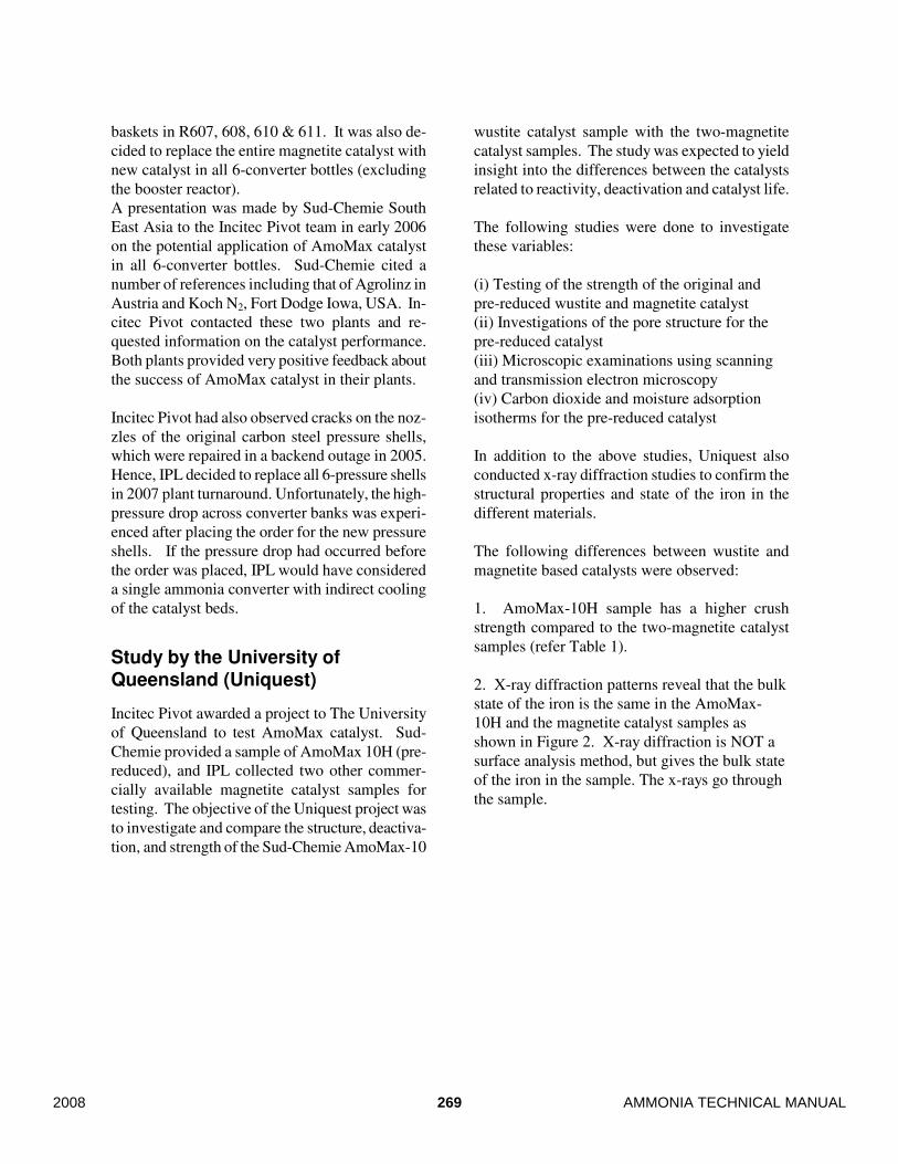
2. X-ray diffraction patterns reveal that the bulk
state of the iron is the same in the AmoMax-
10H and the magnetite catalyst samples as
shown in Figure 2. X-ray diffraction is NOT a
surface analysis method, but gives the bulk state
of the iron in the sample. The x-rays go through
the sample.
269 AMMONIA TECHNICAL MANUAL2008
Table 1 - Compression test results for different pre-reduced catalyst
Reduced cata-
lyst
Mean
compres-
sive load
(N)
Standard
deviation
for load
(N)
Compressive extension
(mm)
Standard deviation for ex-
tension (mm)
AmoMax-10H 154.1 50.3 0.096 0.013
Magnetite Cata-
lyst -1
36.7 12.1 0.180 0.100
Magnetite Cata-
lyst -2
20.2 7.4 0.124 0.057
Figure 2 - X-ray diffraction patterns for pre-reduced catalysts.
3. The pore structure of wustite and magnetite
catalysts, based on argon adsorption, is similar.
However, the porosity of AmoMax-10H is slightly
less than magnetite, which is consistent with the
lower oxygen content of wustite compared to
magnetite. The results of pore structure analysis
are depicted in Figure 3.
4. The pore structure of the pre-reduced Amo-
Max-10H shows lower accessibility during mer-
cury intrusion, suggesting a greater level of disor-
der in this catalyst, compared to the pre-reduced
magnetite based catalyst.
5. Microscopic examinations show that individual
particles of magnetite-based catalyst are more het-
erogeneous than those of AmoMax-10H, with
macropores consistent with the adsorption analy-
sis. More importantly, however, the internal sur-
face of the AmoMax-10H particles is more defec-
tive, which may contribute to its higher activity.
Micrographs of AmoMax-10H are depicted in
Figure 4.
270AMMONIA TECHNICAL MANUAL 2008
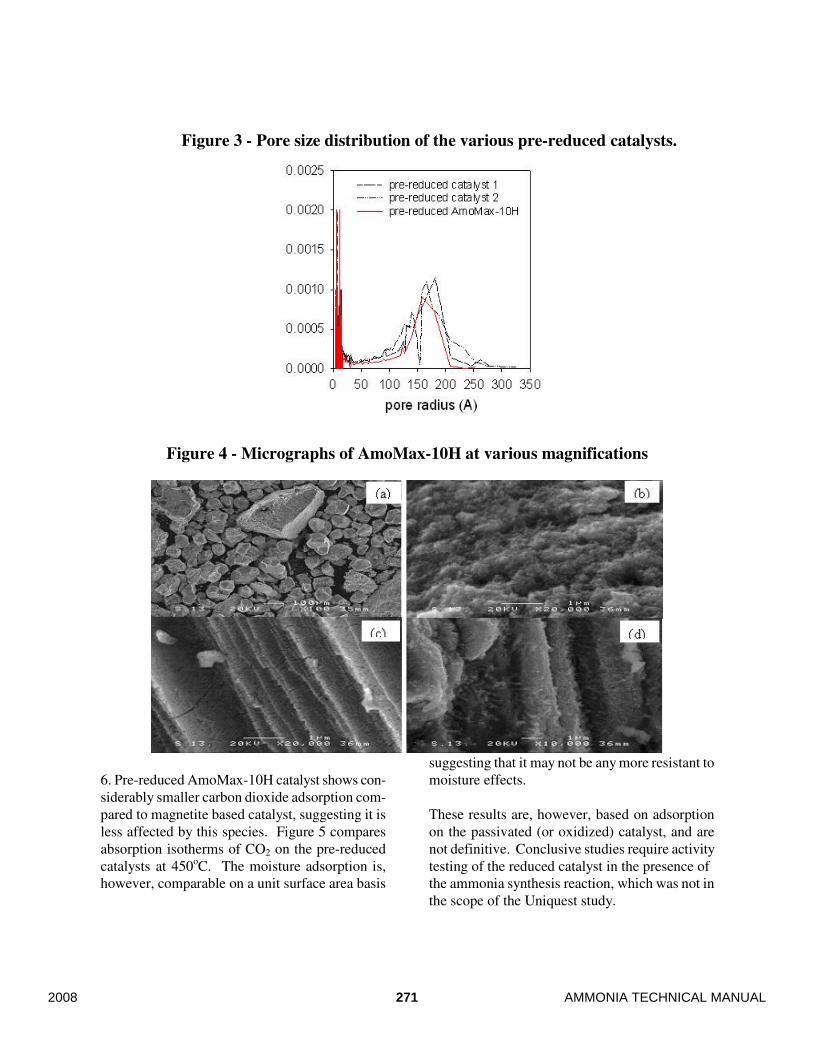
Figure 3 - Pore size distribution of the various pre-reduced catalysts.
Figure 4 - Micrographs of AmoMax-10H at various magnifications
6. Pre-reduced AmoMax-10H catalyst shows con-
siderably smaller carbon dioxide adsorption com-
pared to magnetite based catalyst, suggesting it is
less affected by this species. Figure 5 compares
absorption isotherms of CO2 on the pre-reduced
catalysts at 450oC. The moisture adsorption is,
however, comparable on a unit surface area basis
suggesting that it may not be any more resistant to
moisture effects.
These results are, however, based on adsorption
on the passivated (or oxidized) catalyst, and are
not definitive. Conclusive studies require activity
testing of the reduced catalyst in the presence of
the ammonia synthesis reaction, which was not in
the scope of the Uniquest study.
271 AMMONIA TECHNICAL MANUAL2008
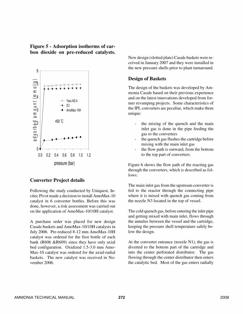
Figure 5 - Adsorption isotherms of car-
bon dioxide on pre-reduced catalysts.
pressure (bar)
0.0 0.2 0.4 0.6 0.8 1.0 1.2
ad
so
rbe
d a
mo
un
t (m
mo
l/g
)
0
1
2
3
4
5
6
Yara AS-4
ICI
AmoMax-10H
450 O
C
Converter Project details
Following the study conducted by Uniquest, In-
citec Pivot made a decision to install AmoMax-10
catalyst in 6 converter bottles. Before this was
done, however, a risk assessment was carried out
on the application of AmoMax-10/10H catalyst.
A purchase order was placed for new design
Casale baskets and AmoMax-10/10H catalysts in
July 2006. Pre-reduced 8-12 mm AmoMax-10H
catalyst was ordered for the first bottle of each
bank (R606 &R609) since they have only axial
bed configuration. Oxidized 1.5-3.0 mm Amo-
Max-10 catalyst was ordered for the axial-radial
baskets. The new catalyst was received in No-
vember 2006.
New design (slotted plate) Casale baskets were re-
ceived in January 2007 and they were installed in
the new pressure shells prior to plant turnaround.
Design of Baskets
The design of the baskets was developed by Am-
monia Casale based on their previous experience
and on the latest innovations developed from for-
mer revamping projects. Some characteristics of
the IPL converters are peculiar, which make them
unique:
- the mixing of the quench and the main
inlet gas is done in the pipe feeding the
gas to the converters
- the quench gas flushes the cartridge before
mixing with the main inlet gas
- the flow path is outward, from the bottom
to the top part of converters.
Figure 6 shows the flow path of the reacting gas
through the converters, which is described as fol-
lows:
The main inlet gas from the upstream converter is
fed to the reactor through the connecting pipe
where it is mixed with quench gas coming from
the nozzle N3 located in the top of vessel.
The cold quench gas, before entering the inlet pipe
and getting mixed with main inlet, flows through
the annulus between the vessel and the cartridge,
keeping the pressure shell temperature safely be-
low the design.
At the converter entrance (nozzle N1), the gas is
diverted to the bottom part of the cartridge and
into the center perforated distributor. The gas
flowing through the center distributor then enters
the catalytic bed. Most of the gas enters radially
272AMMONIA TECHNICAL MANUAL 2008

with the rest axially from the upper part of the
bed.
Figure 6 - Converter Layout
After leaving the catalytic bed, the gas flows
through the outer collector to the bottom part of
the cartridge and exits the converter through noz-
zle N2.
To measure the reacting gas temperature, two
thermowells are inserted into the cartridge, one in-
side the catalytic bed and the other in the bottom
part of cartridge. Particularly, the second one is
specifically designed with a “U” shape: this design
is resulting in a high reliability of temperature
measurement because the measurement point is
located in a zone of the cartridge where the gas is
completely mixed.
Basket Design Features
The design specifically developed for the above-
described converters was studied to achieve the
following goals:
- Full exploitation of catalyst.
- High reliability.
- Easy access to internal baskets for mainte-
nance or catalyst replacement.
As described in the previous paragraph, the react-
ing gas flowing through the catalytic bed has an
axial-radial path, which utilizes all of the catalyst
loaded into the baskets. Due to the particular de-
sign of the converter (outward flow, from bottom
to top, so the axial portion is opposite to the inlet
opening), a thorough analysis of gas flow has been
undertaken with computational fluid dynamic
(CFD) simulation tools. The particular design de-
veloped for the distribution devices ensures equal-
ized distribution between axial and radial flow.
The catalyst is contained and supported between
two cylindrical walls, made by slotted plate.
These plates, constructed of AISI 321 stainless
steel, have the double function of containing the
catalyst (the slot dimensions are designed for this
purpose) and supporting the catalyst (the wall
thickness is calculated based on the catalyst prop-
erties). The construction procedure used to make
these slotted plates is such that it does not affect
the metallurgical structure of the metal (no crack
formation) resulting in high strength of the cylin-
drical walls.
Using the slotted plates for the catalyst bed walls
made possible not to use the wire mesh to contain
the catalyst used in the former design, simplifying
so the mechanical construction of internals.
In the top of catalytic bed, a protection screen is
installed to prevent migration of the catalyst out-
273 AMMONIA TECHNICAL MANUAL2008
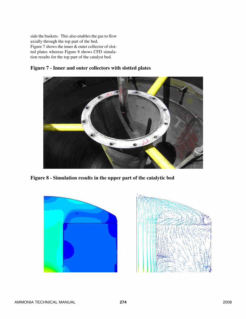
side the baskets. This also enables the gas to flow
axially through the top part of the bed.
Figure 7 shows the inner & outer collector of slot-
ted plates whereas Figure 8 shows CFD simula-
tion results for the top part of the catalyst bed.
Figure 7 - Inner and outer collectors with slotted plates
Figure 8 - Simulation results in the upper part of the catalytic bed
274AMMONIA TECHNICAL MANUAL 2008
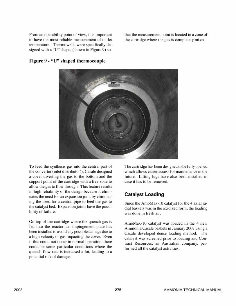
From an operability point of view, it is important
to have the most reliable measurement of outlet
temperature. Thermowells were specifically de-
signed with a “U” shape, (shown in Figure 9) so
that the measurement point is located in a zone of
the cartridge where the gas is completely mixed.
Figure 9 - “U” shaped thermocouple
To feed the synthesis gas into the central part of
the converter (inlet distributor)), Casale designed
a cover diverting the gas to the bottom and the
support point of the cartridge with a free zone to
allow the gas to flow through. This feature results
in high reliability of the design because it elimi-
nates the need for an expansion joint by eliminat-
ing the need for a central pipe to feed the gas to
the catalyst bed. Expansion joints have the possi-
bility of failure.
On top of the cartridge where the quench gas is
fed into the reactor, an impingement plate has
been installed to avoid any possible damage due to
a high velocity of gas impacting the cover. Even
if this could not occur in normal operation, there
could be some particular conditions where the
quench flow rate is increased a lot, leading to a
potential risk of damage.
The cartridge has been designed to be fully opened
which allows easier access for maintenance in the
future. Lifting lugs have also been installed in
case it has to be removed.
Catalyst Loading
Since the AmoMax-10 catalyst for the 4 axial ra-
dial baskets was in the oxidized form, the loading
was done in fresh air.
AmoMax-10 catalyst was loaded in the 4 new
Ammonia Casale baskets in January 2007 using a
Casale developed dense loading method. The
catalyst was screened prior to loading and Con-
tract Resources, an Australian company, per-
formed all the catalyst activities.
275 AMMONIA TECHNICAL MANUAL2008
After completion of the loading activities and pro-
tection screen installation, thermocouples were in-
serted into their thermowells. Thermocouples
measure the temperature in different positions in
the catalytic bed, thus allowing optimisation of the
operation.
Pre-reduced catalyst, AmoMax 10-H catalyst was
loaded under N2 using a dense loading method in
the first bottle of each train. The loaded bulk den-
sities of AmoMax 10-H and AmoMax 10 were 2.7
and 3.1 kg/l respectively.
After final cleaning, the special Casale gas dis-
tributor was placed in position at the reactor inlet
nozzle and the reactor boxed up and made ready
for start-up.
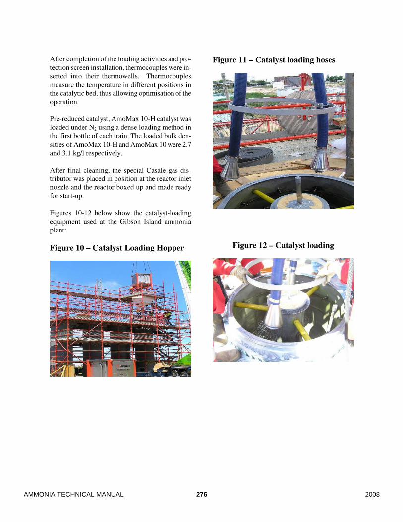
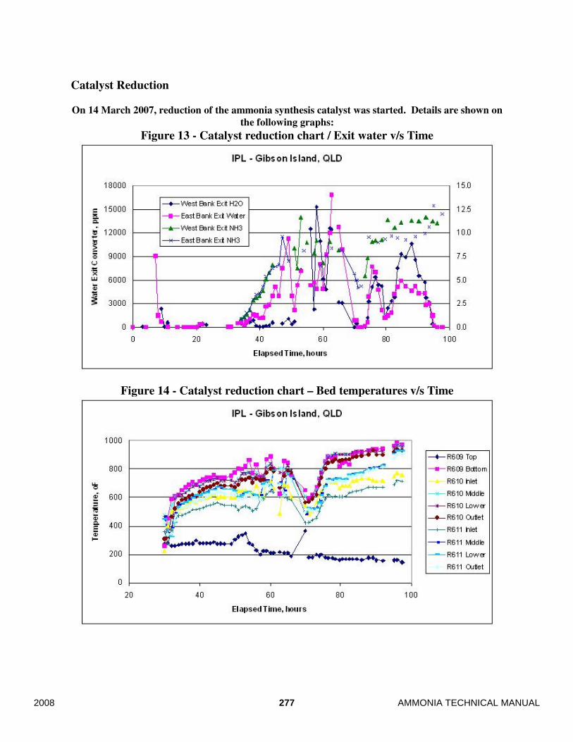
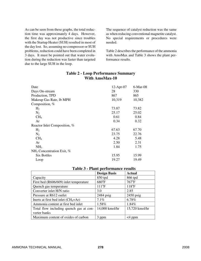
Figures 10-12 below show the catalyst-loading
equipment used at the Gibson Island ammonia
plant:
Figure 10 – Catalyst Loading Hopper
Figure 11 – Catalyst loading hoses
Figure 12 – Catalyst loading
276AMMONIA TECHNICAL MANUAL 2008
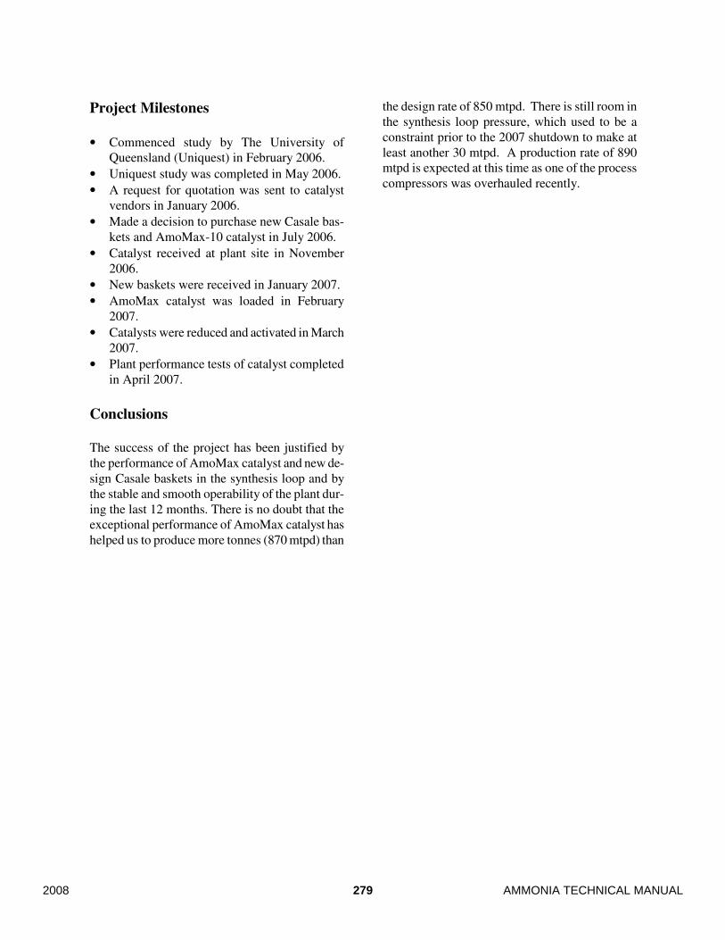
Catalyst Reduction
On 14 March 2007, reduction of the ammonia synthesis catalyst was started. Details are shown on
the following graphs:
Figure 13 - Catalyst reduction chart / Exit water v/s Time
Figure 14 - Catalyst reduction chart – Bed temperatures v/s Time
277 AMMONIA TECHNICAL MANUAL2008
As can be seen from these graphs, the total reduc-
tion time was approximately 4 days. However,
the first day was not productive since troubles
with the Startup Heater (SUH) resulted in most of
the day lost. So, assuming no compressor or SUH
problems, reduction could have been completed in
3 days. It must be pointed out that water evolu-
tion during the reduction was faster than targeted
due to the large SUH in the loop.
The sequence of catalyst reduction was the same
as when reducing conventional magnetite catalyst.
No special requirements or procedures were
needed.
Table 2 describes the performance of the ammonia
with AmoMax and Table 3 shows the plant per-
formance results.
Table 2 - Loop Performance Summary
With AmoMax-10
Date 12-Apr-07 6-Mar-08
Days On-stream 28 330
Production, TPD 867 865
Makeup Gas Rate, lb MPH 10,319 10,382
Composition, %
H2 73.87 73.82
N2 25.17 25.02
CH4 0.61 0.84
Ar 0.34 0.32
Reactor Inlet Composition, %
H2 67.63 67.70
N2 23.75 22.76
CH4 4.28 5.48
Ar 2.50 2.31
NH3 1.84 1.75
NH3 Concentration Exit, %
Six Bottles 15.95 15.99
Loop 19.27 19.49
Table 3 - Plant performance results Design Basis Actual
Capacity 850 tpd 866 tpd
First bed (R606/609) inlet temperature 680oF 767oF
Quench gas temperature 111oF 118oF
Converter inlet H/N ratio 3.0 2.85
Pressure at R612 outlet 2484 psig 2450 psig
Inerts at first bed inlet (CH4+Ar) 7.1% 6.78%
Ammonia content at first bed inlet 1.58% 1.84%
Total flow including quench gas at con-
verter banks
14,000 kmol/hr 15,720 kmol/hr
Maximum content of oxides of carbon 3 ppm <4 ppm
278AMMONIA TECHNICAL MANUAL 2008
Project Milestones
• Commenced study by The University of
Queensland (Uniquest) in February 2006.
• Uniquest study was completed in May 2006.
• A request for quotation was sent to catalyst
vendors in January 2006.
• Made a decision to purchase new Casale bas-
kets and AmoMax-10 catalyst in July 2006.
• Catalyst received at plant site in November
2006.
• New baskets were received in January 2007.
• AmoMax catalyst was loaded in February
2007.
• Catalysts were reduced and activated in March
2007.
• Plant performance tests of catalyst completed
in April 2007.
Conclusions
The success of the project has been justified by
the performance of AmoMax catalyst and new de-
sign Casale baskets in the synthesis loop and by
the stable and smooth operability of the plant dur-
ing the last 12 months. There is no doubt that the
exceptional performance of AmoMax catalyst has
helped us to produce more tonnes (870 mtpd) than
the design rate of 850 mtpd. There is still room in
the synthesis loop pressure, which used to be a
constraint prior to the 2007 shutdown to make at
least another 30 mtpd. A production rate of 890
mtpd is expected at this time as one of the process
compressors was overhauled recently.
279 AMMONIA TECHNICAL MANUAL2008

280AMMONIA TECHNICAL MANUAL 2008
Recommended