www.elsevier.com/locate/enconman
Energy Conversion and Management 48 (2007) 1273–1280
Feasibility study of one axis three positions tracking solar PV withlow concentration ratio reflector
B.J. Huang *, F.S. Sun
Department of Mechanical Engineering, National Taiwan University, Taipei 106, Taiwan, ROC
Received 20 March 2006; accepted 27 September 2006Available online 29 November 2006
Abstract
A new PV design, called ‘‘one axis three position sun tracking PV module’’, with low concentration ratio reflector was proposed in thepresent study. Every PV module is designed with a low concentration ratio reflector and is mounted on an individual sun tracking frame.The one axis tracking mechanism adjusts the PV position only at three fixed angles (three position tracking): morning, noon and after-noon. This ‘‘one axis three position sun tracking PV module’’ can be designed in a simple structure with low cost. A design analysis wasperformed in the present study. The analytical results show that the optimal stopping angle b in the morning or afternoon is about 50�from the solar noon position and the optimal switching angle that controls the best time for changing the attitude of the PV module ishalf of the stopping angle, i.e. hH = b/2, and both are independent of the latitude. The power generation increases by approximately24.5% as compared to a fixed PV module for latitude / < 50�. The analysis also shows that the effect of installation misalignment awayfrom the true south direction is negligible (<2%) if the alignment error is less than 15�. An experiment performed in the present studyindicates that the PV power generation can increase by about 23% using low concentration (2X) reflectors. Hence, combining with thepower output increase of 24.5%, by using one axis three position tracking, the total increase in power generation is about 56%. The eco-nomic analysis shows that the price reduction is between 20% and 30% for the various market prices of flat plate PV modules.� 2006 Elsevier Ltd. All rights reserved.
Keywords: Solar photovoltaic; Solar power; Tracking PV; Concentrator PV
1. Introduction
The electricity generation cost of solar PV (photovol-taic) systems is still very high, several times that of conven-tional power generation. This makes the dissemination ofsolar PV very difficult.
The tracking flat PV system is one of the methods toreduce the power generation cost. Neville [11] has showntheoretically that for a mid latitude region (/ = 30�), com-pared to a fixed PV module tilted at an angle equal to thelocal latitude, the power generation can increase about 41%using two axis tracking. For a one axis tracking PV system,the power increase is 36%. Several approaches to track thesun using a one axis open loop [6], two axis closed loop [10]
0196-8904/$ - see front matter � 2006 Elsevier Ltd. All rights reserved.
doi:10.1016/j.enconman.2006.09.020
* Corresponding author. Tel.: +886 2 23634790; fax: +886 2 23640549.E-mail address: [email protected] (B.J. Huang).
and two axis open loop [12] tracking have been proposedby many researchers. There are also many different control-lers to implement the control schemes, e.g. PLA [1] (pro-grammable logic array), PC [14] and microprocessor [7].
Another solution toward cost reduction [3] is to usereflector or Fresnel lens [4] to concentrate the solar radia-tion incident upon a high efficiency solar cell [13]. It hasbeen shown experimentally that the concentrator PV pro-duces 37% more energy than the flat plate module in aone year comparison in Northern California. The area ofPV can be largely reduced if the concentration ratio is high(>100X). However, this requires a high precision two axissun tracking technology, which is very sophisticated,expensive and less reliable. In the present study, we pro-pose a new idea of one axis three position tracking PVmodule with low concentration ratio reflector to providea more simple PV tracking system, which can reduce thepower generation cost.
Nomenclature
A altitude of observer, kilometersa0; a1; k; a�0; a
�1; k�; r0; r1; rk parameters for sb, dimension-
lessG0 extraterrestrial (AM0) solar radiation on hori-
zontal plane, W/m2
Gbn beam radiation on horizontal plane, W/m2
Gsc solar constant, 1353 W/m2
H height of shading plate, mmIc clear sky horizontal radiation, J/m2
Icb clear sky horizontal beam radiation, J/m2
Icd clear sky horizontal diffuse radiation, J/m2
I0n extraterrestrial (AM0) solar radiation, J/m2
IT solar radiation on tilted plane, J/m2
L distance between photosensing element andshading plate, mm
n nth day of year, dayPv PV module size, WpQopt optimal yearly total solar incident radiation,
MJ/m2
Qtotal yearly total solar incident radiation, MJ/m2
Rb ratio of beam radiation on tilted surface to thaton horizontal surface, dimensionless
X concentration ratio, timesa tilt angle of tracker, degreeb stopping angle of tracker, degreec installation error of tracker, degreed declination, degreeh solar incident angle with respect to PV normal
vector, degreehH switching angle of tracker, degreehz solar incident zenith angle, degreek slope of PV surface, dimensionlessq diffuse ground reflectance, dimensionlesssb atmosphere transmittance for beam radiation,
dimensionlesssd atmosphere transmittance for diffuse radiation,
dimensionless/ latitude of installation location, degreex solar time hour angle, degree
1274 B.J. Huang, F.S. Sun / Energy Conversion and Management 48 (2007) 1273–1280
2. Design analysis of one axis three position sun tracking PV
module
2.1. Design of one axis sun tracking PV module
The conventional one axis sun tracking system requirescontinuous tracking using feedback or open loop control.The tracker is usually designed in a large scale in orderto mount multiple flat PV modules. This makes the struc-ture very heavy, complicated and not easy to install. Wepropose the idea of a simple one axis sun tracking PV mod-ule. Every PV module is mounted on an individual suntracking frame. The one axis tracking mechanism adjuststhe PV position only at three fixed angles (three positiontracking): morning, noon and afternoon. We call this‘‘one axis three position sun tracking PV’’. The tracker isdesigned in simple structure with low cost.
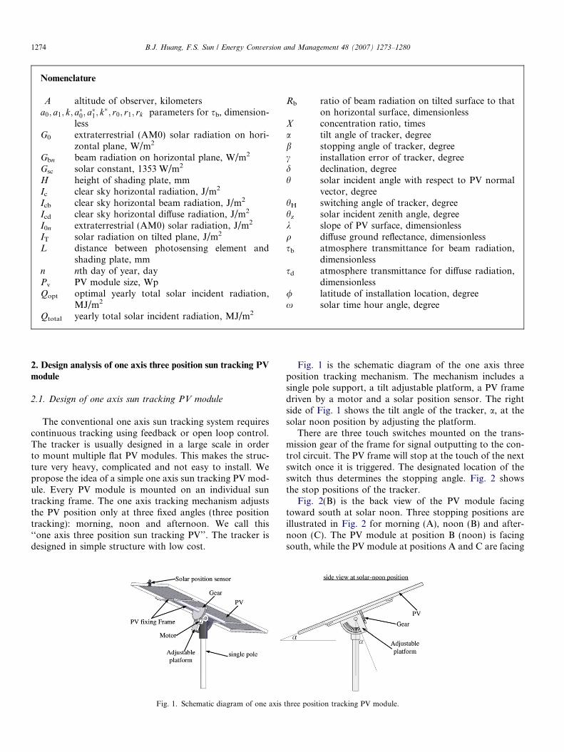
Fig. 1. Schematic diagram of one axis
Fig. 1 is the schematic diagram of the one axis threeposition tracking mechanism. The mechanism includes asingle pole support, a tilt adjustable platform, a PV framedriven by a motor and a solar position sensor. The rightside of Fig. 1 shows the tilt angle of the tracker, a, at thesolar noon position by adjusting the platform.
There are three touch switches mounted on the trans-mission gear of the frame for signal outputting to the con-trol circuit. The PV frame will stop at the touch of the nextswitch once it is triggered. The designated location of theswitch thus determines the stopping angle. Fig. 2 showsthe stop positions of the tracker.
Fig. 2(B) is the back view of the PV module facingtoward south at solar noon. Three stopping positions areillustrated in Fig. 2 for morning (A), noon (B) and after-noon (C). The PV module at position B (noon) is facingsouth, while the PV module at positions A and C are facing
three position tracking PV module.
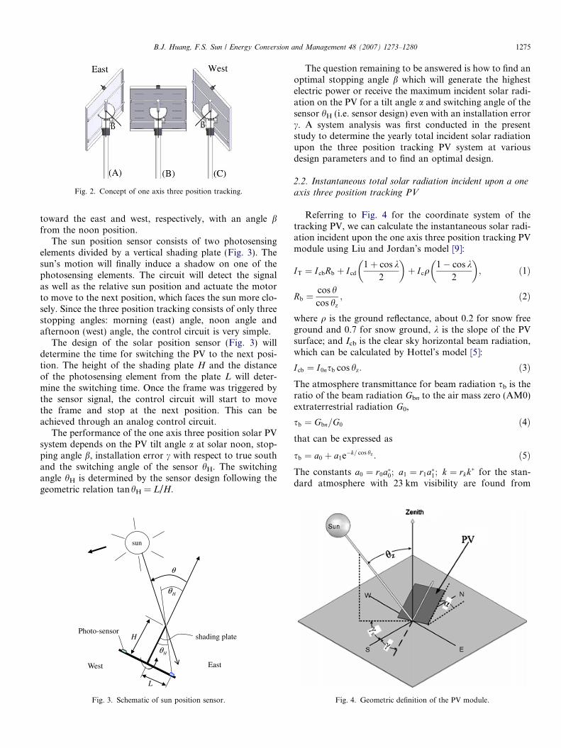
Fig. 2. Concept of one axis three position tracking.
B.J. Huang, F.S. Sun / Energy Conversion and Management 48 (2007) 1273–1280 1275
toward the east and west, respectively, with an angle bfrom the noon position.
The sun position sensor consists of two photosensingelements divided by a vertical shading plate (Fig. 3). Thesun’s motion will finally induce a shadow on one of thephotosensing elements. The circuit will detect the signalas well as the relative sun position and actuate the motorto move to the next position, which faces the sun more clo-sely. Since the three position tracking consists of only threestopping angles: morning (east) angle, noon angle andafternoon (west) angle, the control circuit is very simple.
The design of the solar position sensor (Fig. 3) willdetermine the time for switching the PV to the next posi-tion. The height of the shading plate H and the distanceof the photosensing element from the plate L will deter-mine the switching time. Once the frame was triggered bythe sensor signal, the control circuit will start to movethe frame and stop at the next position. This can beachieved through an analog control circuit.
The performance of the one axis three position solar PVsystem depends on the PV tilt angle a at solar noon, stop-ping angle b, installation error c with respect to true southand the switching angle of the sensor hH. The switchingangle hH is determined by the sensor design following thegeometric relation tanhH = L/H.
H
sun
East
H
L
H
West
Photo-sensor shading plate
Fig. 3. Schematic of sun position sensor.
The question remaining to be answered is how to find anoptimal stopping angle b which will generate the highestelectric power or receive the maximum incident solar radi-ation on the PV for a tilt angle a and switching angle of thesensor hH (i.e. sensor design) even with an installation errorc. A system analysis was first conducted in the presentstudy to determine the yearly total incident solar radiationupon the three position tracking PV system at variousdesign parameters and to find an optimal design.
2.2. Instantaneous total solar radiation incident upon a one
axis three position tracking PV
Referring to Fig. 4 for the coordinate system of thetracking PV, we can calculate the instantaneous solar radi-ation incident upon the one axis three position tracking PVmodule using Liu and Jordan’s model [9]:
IT ¼ I cbRb þ Icd
1þ cos k2
� �þ Icq
1� cos k2
� �; ð1Þ
Rb ¼cos hcos hz
; ð2Þ
where q is the ground reflectance, about 0.2 for snow freeground and 0.7 for snow ground, k is the slope of the PVsurface; and Icb is the clear sky horizontal beam radiation,which can be calculated by Hottel’s model [5]:
Icb ¼ I0nsb cos hz: ð3ÞThe atmosphere transmittance for beam radiation sb is theratio of the beam radiation Gbn to the air mass zero (AM0)extraterrestrial radiation G0,
sb ¼ Gbn=G0 ð4Þthat can be expressed as
sb ¼ a0 þ a1e�k= cos hz : ð5ÞThe constants a0 ¼ r0a�0; a1 ¼ r1a�1; k ¼ rkk� for the stan-dard atmosphere with 23 km visibility are found from
Fig. 4. Geometric definition of the PV module.
Latitude 25º PV tilt angle =25º
6000
8000
10000
12000
14000
y²m/J
M( ecnaidarri latot r)
20
25
30
35
40
45
50
,elgna gni hc tiws l
H)g ed(
Optimal stop angle =50ºQopt = 10.280 MJ/m2yrPercentage increase = 24.5%
Qtotal = 8,260 MJ/m2yr(without tracking)
1276 B.J. Huang, F.S. Sun / Energy Conversion and Management 48 (2007) 1273–1280
a�0; a�1, and k*, which are given for altitudes less than2.5 km by
a�0 ¼ 0:4237� 0:00821ð6� A2Þ;a�1 ¼ 0:5055þ 0:00595ð6:5� AÞ2;k� ¼ 0:2711þ 0:01858ð2:5� AÞ2;
ð6Þ
where A is the altitude of the observer in kilometers. Theparameters r0, r1 and rk depend on the climate type andare given in Table 1. The variable I0n is the accumulatedextraterrestrial beam radiation (i.e. at AM0) for a period(i.e. 1 min) on the nth day of the year:
I0n ¼Z
G0n dt ¼Z
Gsc 1þ 0:033 cos360� n
365
� �dt: ð7Þ
Gsc is the solar constant (1353 W/m2). The variable Icd inEq. (1) is the diffuse radiation, which can be calculatedusing Liu and Jordan’s model [8]:
Icd ¼ I0nsd cos hz; ð8Þsd ¼ 0:2710� 0:2939sb: ð9Þ
Referring to Fig. 4, the solar incident angle with respect tothe PV normal vector h, and the zenith angle hz are relatedto the PV installation tilt angle a, stopping angle b and so-lar declination angle d, which can be calculated by Eqs. (10)and (11), which are derived from the relative position of thesun and the PV attitude [2]:
cos h ¼ sin a cos b sin / cos c cos d cos x
� sin a cos b cos c cos / sin d
� sin b sin c sin / cos d cos xþ sin b sin c cos / sin d
þ sin a cos b sin c cos d sin xþ sin b cos c cos d sin x
þ cos a cos b sin / sin dþ cos a cos b cos / cos d sin x;
ð10Þcos hz ¼ cos / cos d cos xþ sin / sin d; ð11Þ
cosk in Eq. (1) is the inner product of the PV normal vectorand the zenith vector, which is given by
cos k ¼ cos a cos b; ð12Þ
d ¼ 23:45 sin 360284þ n
365
� �; deg; ð13Þ
c is the azimuth or installation deviation (misalignment er-ror) angle of the inclined PV surface away from true south(negative for eastward and positive for westward); / is thelatitude of the installation location; x is the solar time hourangle (negative in the morning, positive in the afternoonand zero at solar noon; 15 degree per hour).
Table 1r0, r1, and rk
Climate type r0 r1 rk
Tropical 0.95 0.98 1.02Mid-latitude summer 0.97 0.99 1.02Sub-arctic summer 0.99 0.99 1.01Mid-latitude winter 1.03 1.01 1.00
2.3. Optimal design of one axis three position tracking PV
module
The optimal design of the one axis three position track-ing PV module can be made by calculating the total solarradiation incident upon the PV at various design parame-ters. Given the design parameters, we can calculate theinstantaneous total solar radiation incident upon a one axisthree position tracking PV module using Eqs. (1)–(13). Theyearly total solar incident radiation on the PV surface canthen be calculated through time integration.
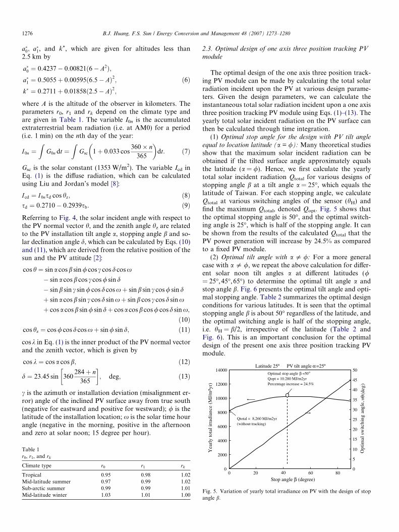
(1) Optimal stop angle for the design with PV tilt angle
equal to location latitude (a = /): Many theoretical studiesshow that the maximum solar incident radiation can beobtained if the tilted surface angle approximately equalsthe latitude (a = /). Hence, we first calculate the yearlytotal solar incident radiation Qtotal for various designs ofstopping angle b at a tilt angle a = 25�, which equals thelatitude of Taiwan. For each stopping angle, we calculateQtotal at various switching angles of the sensor (hH) andfind the maximum Qtotal, denoted Qopt. Fig. 5 shows thatthe optimal stopping angle is 50�, and the optimal switch-ing angle is 25�, which is half of the stopping angle. It canbe shown from the results of the calculated Qtotal that thePV power generation will increase by 24.5% as comparedto a fixed PV module.
(2) Optimal tilt angle with a 5 /: For a more generalcase with a 5 /, we repeat the above calculation for differ-ent solar noon tilt angles a at different latitudes (/= 25�, 45�, 65�) to determine the optimal tilt angle a andstop angle b. Fig. 6 presents the optimal tilt angle and opti-mal stopping angle. Table 2 summarizes the optimal designconditions for various latitudes. It is seen that the optimalstopping angle b is about 50� regardless of the latitude, andthe optimal switching angle is half of the stopping angle,i.e. hH = b/2, irrespective of the latitude (Table 2 andFig. 6). This is an important conclusion for the optimaldesign of the present one axis three position tracking PVmodule.
0
2000
4000
0
Stop angle (degree)
ylraeY
0
5
10
15 amitp
O
20 40 60 80
Fig. 5. Variation of yearly total irradiance on PV with the design of stopangle b.
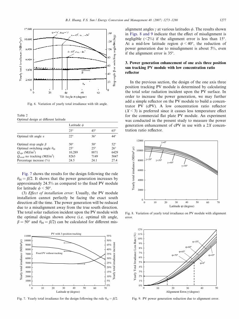
Fig. 6. Variation of yearly total irradiance with tilt angle.
Table 2Optimal design at different latitude
Latitude /
25� 45� 65�
Optimal tilt angle a 22� 36� 44�
Optimal stop angle b 50� 50� 52�Optimal switching angle hH 25� 25� 26�Qopt (MJ/m2) 10,289 8871 6429Qtotal no tracking (MJ/m2) 8263 7149 5047Percentage increase (%) 24.5 24.1 27.4
0
2000
4000
6000
8000
10000
12000
)ry ²m/J
M( ecnaidarri latot ylraeY
γ =0º
γ =20º
γ =50ºγ =40º
γ =30º
0 10 20 30 40 50 60 70
Fig. 8. Variation of yearly total irradiance on PV module with alignmenterror.
B.J. Huang, F.S. Sun / Energy Conversion and Management 48 (2007) 1273–1280 1277
Fig. 7 shows the results for the design following the rulehH = b/2. It shows that the power generation increases byapproximately 24.5% as compared to the fixed PV modulefor latitude / < 50�.
(3) Effect of installation error: Usually, the PV moduleinstallation cannot perfectly be facing the exact southdirection all the time. The power generation will be reduceddue to a misalignment away from the true south direction.The total solar radiation incident upon the PV module withthe optimal design shown above (i.e. optimal tilt angle,b = 50� and hH = b/2) can be calculated for different mis-
0
1000
2000
3000
4000
5000
6000
7000
8000
9000
10000
11000
0
)ry²m/J
M( Y
earl
y to
tal i
rrad
ianc
e
0%
5%
10%
15%
20%
25%
30%
35%
40%
45%
50%
55%
Yea
rly
tota
l irr
adia
nce
incr
ease
Fixed PV without tracking
PV with 3-position tracking
10 20 30 40 50 60 70
Fig. 7. Yearly total irradiance for the design following the rule hH = b/2.
alignment angles c at various latitudes /. The results shownin Figs. 8 and 9 indicate that the effect of misalignment isnegligible (<2%) if the alignment error is less than 15�.At a mid-low latitude region / < 40�, the reduction ofpower generation due to misalignment is about 5%, evenif the alignment error is 35�.
3. Power generation enhancement of one axis three position
sun tracking PV module with low concentration ratio
reflector
In the previous section, the design of the one axis threeposition tracking PV module is determined by calculatingthe total solar radiation incident upon the PV surface. Inorder to increase the power generation, we may furtheradd a simple reflector on the PV module to build a concen-trator PV (cPV). A low concentration ratio reflector(X < 3) is preferred since it causes less temperature effectfor the commercial flat plate PV module. An experimentwas conducted in the present study to measure the powergeneration enhancement of cPV in use with a 2X concen-tration ratio reflector.
0%
1%
2%
3%
4%
5%
6%
7%
8%
9%
10%
11%
12%
0
Alignment Error, (degree)
)%( eta
R ssoL ecnaidarrI la to
T ylraeY
=55º
10 20 30 40 50
Fig. 9. PV power generation reduction due to alignment error.
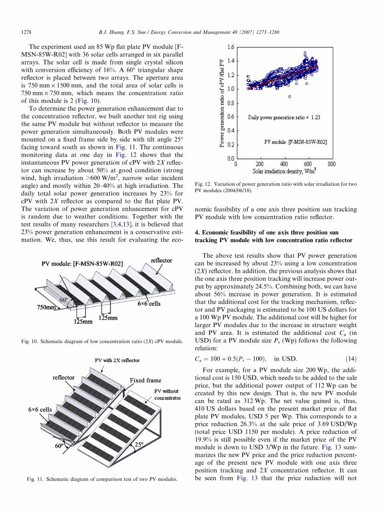
Fig. 12. Variation of power generation ratio with solar irradiation for twoPV modules (2004/06/18).
1278 B.J. Huang, F.S. Sun / Energy Conversion and Management 48 (2007) 1273–1280
The experiment used an 85 Wp flat plate PV module [F-MSN-85W-R02] with 36 solar cells arranged in six parallelarrays. The solar cell is made from single crystal siliconwith conversion efficiency of 16%. A 60� triangular shapereflector is placed between two arrays. The aperture areais 750 mm · 1500 mm, and the total area of solar cells is750 mm · 750 mm, which means the concentration ratioof this module is 2 (Fig. 10).
To determine the power generation enhancement due tothe concentration reflector, we built another test rig usingthe same PV module but without reflector to measure thepower generation simultaneously. Both PV modules weremounted on a fixed frame side by side with tilt angle 25�facing toward south as shown in Fig. 11. The continuousmonitoring data at one day in Fig. 12 shows that theinstantaneous PV power generation of cPV with 2X reflec-tor can increase by about 50% at good condition (strongwind, high irradiation >600 W/m2, narrow solar incidentangle) and mostly within 20–40% at high irradiation. Thedaily total solar power generation increases by 23% forcPV with 2X reflector as compared to the flat plate PV.The variation of power generation enhancement for cPVis random due to weather conditions. Together with thetest results of many researchers [3,4,13], it is believed that23% power generation enhancement is a conservative esti-mation. We, thus, use this result for evaluating the eco-
Fig. 10. Schematic diagram of low concentration ratio (2X) cPV module.
Fig. 11. Schematic diagram of comparison test of two PV modules.
nomic feasibility of a one axis three position sun trackingPV module with low concentration ratio reflector.
4. Economic feasibility of one axis three position sun
tracking PV module with low concentration ratio reflector
The above test results show that PV power generationcan be increased by about 23% using a low concentration(2X) reflector. In addition, the previous analysis shows thatthe one axis three position tracking will increase power out-put by approximately 24.5%. Combining both, we can haveabout 56% increase in power generation. It is estimatedthat the additional cost for the tracking mechanism, reflec-tor and PV packaging is estimated to be 100 US dollars fora 100 Wp PV module. The additional cost will be higher forlarger PV modules due to the increase in structure weightand PV area. It is estimated the additional cost Ca (inUSD) for a PV module size Pv (Wp) follows the followingrelation:
Ca ¼ 100þ 0:5ðP v � 100Þ; in USD: ð14ÞFor example, for a PV module size 200 Wp, the addi-
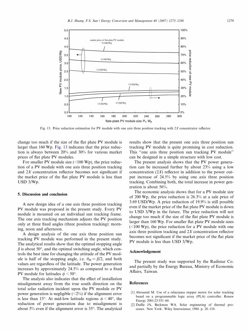
tional cost is 150 USD, which needs to be added to the saleprice, but the additional power output of 112 Wp can becreated by this new design. That is, the new PV modulecan be rated as 312 Wp. The net value gained is, thus,410 US dollars based on the present market price of flatplate PV modules, USD 5 per Wp. This corresponds to aprice reduction 26.3% at the sale price of 3.69 USD/Wp(total price USD 1150 per module). A price reduction of19.9% is still possible even if the market price of the PVmodule is down to USD 3/Wp in the future. Fig. 13 sum-marizes the new PV price and the price reduction percent-age of the present new PV module with one axis threeposition tracking and 2X concentration reflector. It canbe seen from Fig. 13 that the price reduction will not
market price of flat-plate PV module5 USD/Wp
4 USD/Wp
3 USD/Wp
4 USD/Wp
5 USD/Wp
3 USD/Wp
1000.0
0.5
1.0
1.5
2.0
2.5
3.0
3.5
4.0
4.5
5.0
120 140 160 180 200 220 280 300240 260
flate-plate PV module size Pv, Wp
price reduction of new P
V m
oduleNew
PV
mod
ule
pric
e, U
SD
/Wp
0%
10%
20%
30%
40%
50%
60%
70%
80%
90%
100%
Fig. 13. Price reduction estimation for PV module with one axis three position tracking with 2X concentrator reflector.
B.J. Huang, F.S. Sun / Energy Conversion and Management 48 (2007) 1273–1280 1279
change too much if the size of the flat plate PV module islarger than 160 Wp. Fig. 13 indicates that the price reduc-tion is always between 20% and 30% for various marketprices of flat plate PV modules.
For smaller PV module size (<100 Wp), the price reduc-tion of a PV module with one axis three position trackingand 2X concentration reflector becomes not significant ifthe market price of the flat plate PV module is less thanUSD 3/Wp.
5. Discussion and conclusion
A new design idea of a one axis three position trackingPV module was proposed in the present study. Every PVmodule is mounted on an individual sun tracking frame.The one axis tracking mechanism adjusts the PV positiononly at three fixed angles (three position tracking): morn-ing, noon and afternoon.
A design analysis of the one axis three position suntracking PV module was performed in the present study.The analytical results show that the optimal stopping angleb is about 50�, and the optimal switching angle, which con-trols the best time for changing the attitude of the PV mod-ule is half of the stopping angle, i.e. hH = b/2, and bothvalues are regardless of the latitude. The power generationincreases by approximately 24.5% as compared to a fixedPV module for latitudes / < 50�.
The analysis also indicates that the effect of installationmisalignment away from the true south direction on thetotal solar radiation incident upon the PV module or PVpower generation is negligible (<2%) if the alignment erroris less than 15�. At mid-low latitude regions / < 40�, thereduction of power generation due to misalignment isabout 5% even if the alignment error is 35�. The analytical
results show that the present one axis three position suntracking PV module is quite promising in cost reduction.This ‘‘one axis three position sun tracking PV module’’can be designed in a simple structure with low cost.
The present analysis shows that the PV power genera-tion can be increased further by about 23% using a lowconcentration (2X) reflector in addition to the power out-put increase of 24.5% by using one axis three positiontracking. Combining both, the total increase in power gen-eration is about 56%.
The economic analysis shows that for a PV module sizeof 200 Wp, the price reduction is 26.3% at a sale price of3.69 USD/Wp. A price reduction of 19.9% is still possibleeven if the market price of the flat plate PV module is downto USD 3/Wp in the future. The price reduction will notchange too much if the size of the flat plate PV module islarger than 160 Wp. For smaller flat plate PV module sizes(<100 Wp), the price reduction for a PV module with oneaxis three position tracking and 2X concentration reflectorbecomes not significant if the market price of the flat platePV module is less than USD 3/Wp.
Acknowledgement
The present study was supported by the Radistar Co.and partially by the Energy Bureau, Ministry of EconomicAffairs, Taiwan.
References
[1] Abouzeid M. Use of a reluctance stepper motor for solar trackingbased on a programmable logic array (PLA) controller. RenewEnergy 2001;23:551–60.
[2] Duffie JA, Beckman WA. Solar engineering of thermal pro-cesses. New York: Wiley Interscience; 1980. p. 28–110.
1280 B.J. Huang, F.S. Sun / Energy Conversion and Management 48 (2007) 1273–1280
[3] Fraas L, McConnell B. High power density photovoltaics – a path tocost-competitive solar electric power. Renew Energy World 2002;5(5):99–110.
[4] Garboushian V, Roubideaux D, Yoon S. Integrated high-concentra-tion PV near-term alternative for low-cost large-scale solar electricpower. Solar Energy Mater Solar Cells 1997;47(1–4):315–23.
[5] HottelHC.Asimplemodelforestimatingthetransmittanceofdirectsolarradiationthroughclearatmospheres.SolarEnergy1976;18(2):129–34.
[6] Kalogirou SA. Design and construction of a one-axis sun-trackingsystem. Solar Energy 1996;57(6):465–9.
[7] Koyuncu B, Balasubramanian K. A microprocessor controlled auto-matic sun tracker. IEEE Trans Consum Electron 1991;37(4): 913–917.
[8] Liu BYH, Jordan RC. The interrelationship and characteristicdistribution of direct, diffuse and total solar radiation. Solar Energy1960;4(3):1–19.
[9] Liu BYH, Jordan RC. The long-term average performance of flat-plate solar energy collectors. Solar Energy 1963;7(2):53–74.
[10] Lynch WA, Salameh ZM. Simple electro-optically controlled dual-axis sun tracker. Solar Energy 1990;45(2):65–9.
[11] Neville RC. Solar energy collector orientation and tracking mode.Solar Energy 1978;20(1):7–11.
[12] Park K, Lee JH, Kim SH, Kwak YK. Direct tracking controlusing time-optimal trajectories. Control Eng Practice 1996;4(9):1231–1240.
[13] Verlinden PJ, Terao A, Daroczi S, Crane RA, Mulligan WP,Cudzinovic MJ, et al. One-year comparison of a concentratormodule with silicon point-contact solar cell to a fixed flat platemodule in Northern California. In: Proceedings of the 16thEuropean photovoltaic solar energy conference, May 1–5, 2000,Glasgow, UK, 2000. <http://www.sunpowercorp.com/html/Resources/TP_index.html>.
[14] Yousef HA. Design and implementation of a fuzzy logic computer-controlled sun tracking system. Proc IEEE Int Symp Ind Electron1999;3:1030–4.
Recommended