CDWM 1 ADDENDUM NO. 1 DWM PROJECT NO. 13-102 SPECIFICATION NO. 146286A
February 28, 2018
Addendum No. 1
Central Park Pumping Station Electrification Project DWM PROJECT NO. 13-102
SPECIFICATION NO. 146286A
For which bids will be opened in the office of the Department of Procurement Services, Room 103, City Hall Chicago, Illinois 60602, on Tuesday, April 10, 2018 at 11:00 a.m. Chicago time.
BIDDER WILL ACKNOWLEDGE RECEIPT OF THIS ADDENDUM IN THE SPACE PROVIDED ON THE PROPOSAL PAGE
REVISION 1
NOTICE OF Addendum
Book 1 – Terms and Conditions for Construction 1. None.
Book 2 – Instructions and Execution Documents 1. In Section One – Project Information, on Page 4 under Inspection of Site, replace text
“Site inspections are available on Wednesdays at 8:00 AM beginning on the first Wednesday following the date of the Pre-Bid Conference...” with “Site inspections are available on Tuesdays at 8:00 AM beginning on the first Tuesday following the date of the Pre-Bid Conference...”.
Book 3 – Technical Specifications
1. The following Sections were inadvertently omitted from Book 3, Volume II of II, and are included in this Addendum No. 1.
40 05 01 – Supports and Anchors 40 05 10 – Erecting and Jointing Interior and Exposed Exterior Piping 40 05 16 – Ductile-Iron Pipe and Fittings 40 05 17 – Steel Pipe and Fittings 40 05 18 – Miscellaneous Pipe and Fittings 40 05 20 – Valves

CDWM 2 ADDENDUM NO. 1 DWM PROJECT NO. 13-102 SPECIFICATION NO. 146286A
40 42 00 – Mechanical Insulation – Process 40 80 50 – Process Control System Commissioning 40 90 00 – Process Control System General Requirements 40 90 50 – Process Control System Description 40 91 00 – Process Control System Instruments 40 93 50 – Fiber Optic Cable and Accessories
2. Section 40 94 13, 2.10.M. – First sentence, replace text “Allocated adequate hours for additional…” with “Allocate 400 hours for additional…”.
Drawings:
1. None. Questions: Question No. 1 Specification Section 40 94 13 -2.10.M Reads: “Allocate adequate hours for additional HMI programming at the eleven pumping stations for configuration and modifications requested by Commissioner. These hours do not include the programming time required to implement the CPPS operation at these remote locations. The commissioner shall advise the Contractor of the purpose and functions of this additional programming when appropriate.” This is an undefined amount of time being requested on a fix priced project. Can the City either provide an estimated number of hours to be included, or some guidelines as to what may be in need of changing? Otherwise may I suggest striking this from the contract and either handling it as a change order when the time arises or dealing with the need with the previously Contracted Maintenance Integrators. Answer: Addressed in this Addendum No. 1.
END OF ADDENDUM

CDWMCPPS 40 05 01-1 Supports And Anchors
Addendum No. 1
SECTION 40 05 01
SUPPORTS AND ANCHORS
PART 1 GENERAL
1.1 SUMMARY
A. Section Includes: Requirements for providing all hanging and supporting devices
of construction shown, specified, or required for pipelines, apparatus, and
equipment other than electrical equipment.
B. Related work specified in other Sections includes, but is not limited to, the
following:
1. Section 01 11 10 - Compliance with Iron and Steel Requirements
2. Section 05 05 13 - Galvanizing
3. Section 05 12 00 - Structural Steel
4. Section 05 56 00 - Metal Castings
5. Section 09 96 00 - High Performance Coatings
6. Section 40 05 10 - Erecting and Jointing Interior and Exposed Exterior
Piping
7. Section 40 05 16 - Ductile Iron Pipe and Fittings
8. Section 40 05 17 - Steel Pipe and Fittings
C. Comply with the “American Iron and Steel (AIS)” requirements as contained in
Section 436 of the Consolidated Appropriations Act, 2014, further described in
Section 01 11 10 Compliance with Iron and Steel Requirements.
1.2 REFERENCES
A. Codes and standards referred to in this Section are:
1. ASME B16.1 - Cast Iron Pipe Flanges and Flanged Fittings, Class
25, 125, 250, 800
2. ASME B31.1 - Power Piping (Includes Revision Service)
3. ASTM A 307 - Specification for Carbon Steel Bolts and Studs,
60,000 PSI Tensile Strength
4. MSS SP-58 - Pipe Hangers and Supports - Materials, Design
and Manufacture
CDWMCPPS 40 05 01-2 Supports And Anchors
Addendum No. 1
5. MSS SP-69 - Pipe Hangers and Supports - Selection and
Application
6. MSS SP-89 - Pipe Hangers and Supports - Fabrication and
Installation Practices
7. MSS SP-90 - Guidelines on Terminology for Pipe Hangers and
Supports
1.3 SUBMITTALS
A. General: Provide all submittals, including the following, as specified in
Division 1.
B. Shop Drawings: Submit shop drawings to show the quantity, type, design and
location of all supports, hangers and anchors required.
C. Submit a certificate, signed and sealed by a Licensed Professional Engineer
experienced in structural Engineering and registered in the State of Illinois, that
certifies that the Licensed Professional Engineer has evaluated and approved the
Contractor’s supports and anchors as detailed on the submittal drawings and has
prepared complete design calculations confirming the adequacy of all supports,
hangers, anchors and expansion compensating devices used. Provide a separate
certificate for each piping system before starting the installation.
1.4 SYSTEM DESCRIPTION
A. General: System includes supporting devices adequate to maintain the pipelines,
apparatus, and equipment in proper position and alignment under all operating and
testing conditions with due allowance for expansion and contraction. Unless
otherwise shown or specified, provide steel hangers and supports.
B. Design Requirements: Design supporting devices in accordance with the best
practice and provide supporting devices that are not unnecessarily heavy. Design
supporting devices to accommodate loads imposed during leakage tests for the test
pressures specified. Base the required strength of supporting devices on the
combined weight of the piping and connected equipment, the weight of the denser
of the fluids used in operations or testing and the weight of insulation where
applicable. Install supports with a working safety factor of not less than 5, and
conform installation to requirements of Section 05 12 00.
C. Provide springs where necessary. Make hangers and supports of standard design
where possible and best suited for the service required. Include proper pipe
protection saddles for hangers and supports on pipes which are covered with
insulation. Where required, make supports screw adjustable after installation
unless approved otherwise.

CDWMCPPS 40 05 01-3 Supports And Anchors
Addendum No. 1
D. Provide spring hangers at points that are subject to vertical thermal movement or
as shown. Provide pre-engineered type spring hangers with housed and guided
spring coils as recommended by the manufacturer. Provide load indicator, load
scale on an identification plate and a rod turnbuckle for each spring hanger.
Provide spring hangers capable of accommodating at least 1-1/4 inches of
deflection to solid compression.
E. Interference: Design all supporting devices so as to minimize interference with
access and movement. Eliminate the potential for injuries due to protruding
supporting devices.
F. Sizing: Provide base piping support, hanger rod size, brackets and spacing
meeting the requirements of ASME B31.1, MSS SP-58, SP-69, SP-89 and SP-90
except as modified herein.
1. Modify hangers for plastic pipes to increase the bearing area by inserting a
protective sleeve of medium-gauge aluminum sheet metal between the pipe
and the hanger.
a. Align hangers such that no sharp edges come in contact with the pipe.
b. Provide a thermoplastic pad between the plastic pipe and any concrete
or masonry surface.
c. Use supports for vertical lines of a type which do not exert a
compressive strain on the pipe. Riser-type clamps that squeeze the
pipe will not be permitted.
1.5 DELIVERY, STORAGE AND HANDLING
A. Deliver, store and handle all products and materials as specified in Division 1.
1.6 SPARE PARTS
A. Not Used
PART 2 PRODUCTS
2.1 MANUFACTURERS
A. Acceptable manufacturers are listed below.
1. Pipe hangers and supports
a. Grinnell Corporation, Cranston, RI
b. Globe Pipe Hanger Products, Inc., Cleveland, OH
CDWMCPPS 40 05 01-4 Supports And Anchors
Addendum No. 1
2. Sheet metal shield
a. "Thermal-Hanger Shields" by Pipe Shields Incorporated, Vacaville,
CA
b. Thermal Pipe Shields, Stanwood, WA
2.2 MATERIALS
A. Use structural and miscellaneous steel, metal castings, ductile iron pipe and
fittings, steel pipe and fittings, and supports meeting the requirements of Sections
05 12 00.
B. Support overhead hangers using threaded rods properly fastened in place by
suitable screws, clamps, inserts, or bolts, or by welding. Subject hangers to tensile
loading only. Where lateral or axial movement may occur, provide suitable
linkage to permit sway.
C. Suspended Piping: Support suspended piping by adjustable ring or clevis hangers
and threaded rods from heavy duty concrete inserts or other fastening devices,
except as otherwise specified or noted.
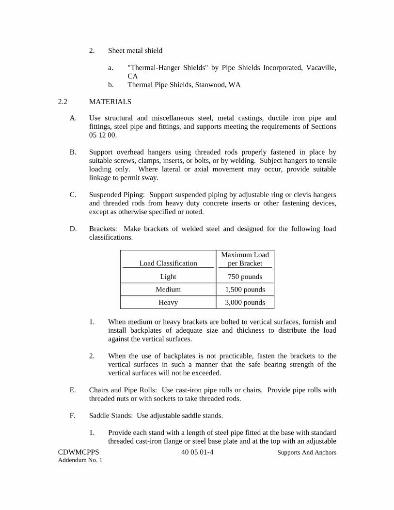
D. Brackets: Make brackets of welded steel and designed for the following load
classifications.
Load Classification Maximum Load
per Bracket
Light 750 pounds
Medium 1,500 pounds
Heavy 3,000 pounds
1. When medium or heavy brackets are bolted to vertical surfaces, furnish and
install backplates of adequate size and thickness to distribute the load
against the vertical surfaces.
2. When the use of backplates is not practicable, fasten the brackets to the
vertical surfaces in such a manner that the safe bearing strength of the
vertical surfaces will not be exceeded.
E. Chairs and Pipe Rolls: Use cast-iron pipe rolls or chairs. Provide pipe rolls with
threaded nuts or with sockets to take threaded rods.
F. Saddle Stands: Use adjustable saddle stands.
1. Provide each stand with a length of steel pipe fitted at the base with standard
threaded cast-iron flange or steel base plate and at the top with an adjustable

CDWMCPPS 40 05 01-5 Supports And Anchors
Addendum No. 1
saddle or roll. Bolt the base flange or plate to the floor, foundation or
concrete base.
2. Use stanchions of construction similar to the saddle stand, except fit them at
the top with cast-iron pipe saddle supports or with pipe stanchion saddles
with yokes and nuts.
G. Insulation Support Requirements: At support points, protect insulated pipes by a
360 degree insert of high density, 100 psi, waterproofed calcium silicate encased in
a 360 degree sheet metal shield.
1. Make inserts of the same thickness as the adjoining pipe insulation.
2. Provide the shield length, minimum galvanized sheet metal gauge and
installation procedure in accordance with the manufacturer's
recommendations.
3. Extend insulation inserts one inch beyond the sheet metal shields on cold
water lines, and jacket and vapor seal as required when the abutting
insulation is installed.
H. Expansion: Connect, support and guide piping to permit and control pipe
expansion and contraction and to accommodate building expansion, contraction
and settling without damage to the piping or support system.
1. Furnish and install anchors when specified, shown, or required for holding
the pipelines and equipment in position or alignment. Design anchors for
rigid fastening to the structures, either directly or through brackets.
2. Provide cast-iron chair type anchors for piping with steel straps, except
where anchors form an integral part of pipe fittings or where an anchor of
special design is required.
3. Inserts: Provide galvanized concrete inserts.
a. Design inserts to permit the rods to be adjusted horizontally in one
plane and to lock the rod nut or head automatically.
b. Recess inserts near the upper flange to receive reinforcing rods.
c. Design inserts so that they may be held in position during concrete
placing operations. Design inserts to carry safely the maximum load
that can be imposed by the rod which they engage.
CDWMCPPS 40 05 01-6 Supports And Anchors
Addendum No. 1
PART 3 EXECUTION
3.1 INSTALLATION
A. Install hanger and supports in accordance with the manufacturer's
recommendations and approved shop drawings and as specified in Division 01 and
Section 40 05 10.
3.2 GALVANIZING AND PAINTING
A. Galvanizing: When specified and when supporting uninsulated galvanized piping
system, galvanize hangers and supports as specified in Section 05 05 13.
B. Painting: Paint hangers, supports, anchors, and similar devices as specified in
Section 09 96 00.
C. Touch-Up Painting: Clean and touch-up painting of field welds, bolted
connections and abraded areas as specified in Section 09 96 00.
END OF SECTION

CDWMCPPS 40 05 10-1 Erecting And Jointing Interior
Addendum No. 1 and Exposed Exterior Piping
SECTION 40 05 10
ERECTING AND JOINTING INTERIOR AND EXPOSED EXTERIOR PIPING
PART 1 GENERAL
1.1 SUMMARY
A. Section Includes: Furnishing of supports and hangers and installation of all
interior and exposed exterior piping and supports.
1. Furnish, support, hang and install piping of the materials, coatings and
linings shown or specified at locations as specified or where shown.
B. Related work specified in other Sections includes, but is not limited to, the
following:
1. Section 01 45 50 - Leakage Tests
2. Section 05 05 13 - Galvanizing
3. Section 07 90 00 - Joint Sealers
4. Section 09 96 00 - High Performance Coatings
5. Section 33 13 00 - Disinfection
6. Section 40 05 01 - Supports and Anchors
7. Section 40 42 00 - Mechanical Insulation - Process
1.2 REFERENCES
A. Codes and standards referred to in this Section are:
1. ASME B1.20.1 - Pipe Threads, General Purpose, Inch
2. ASME B31.1 - Power Piping with Addenda
3. AWWA C600 - Installation of Ductile-Iron Water Mains and Their
Appurtenances
1.3 SUBMITTALS
A. Not Used
1.4 SYSTEM DESCRIPTION
A. Not Used

CDWMCPPS 40 05 10-2 Erecting And Jointing Interior
Addendum No. 1 and Exposed Exterior Piping
1.5 DELIVERY, STORAGE AND HANDLING
A. Deliver, store and handle all products and materials as specified in Division 1 and
as follows:
1. Take extreme care in loading and unloading the pipe and fittings. Do the
work slowly using skids or suitable power equipment, and keep the pipe
under control at all times.
2. Handling Procedures: Under no condition is the pipe to be dropped,
bumped, dragged, pushed or moved in any way which will cause damage to
the pipe, lining or coating.
3. Use of Slings: When handling the pipe with a crane, use a suitable pipe
hook or sling around the pipe. Under no condition is the sling to be allowed
to pass through the pipe unless adequate measures are taken to prevent
damage to the pipe ends, lining and coating.
4. Damage: If any piping or fittings are damaged in the process of delivery,
storing, handling, or laying, replace or repair such piping or fittings as
approved.
1.6 SPARE PARTS
A. Not Used
PART 2 PRODUCTS
2.1 MATERIALS
A. Provide hangers and supports and all necessary appurtenances as specified in
Section 40 05 01.
2.2 FABRICATION
A. Coating: Provide all threads coated with a suitable pipe dope, Masters Metallic
Compound, graphite and engine oil, or equal, before jointing.
PART 3 EXECUTION
3.1 PREPARATION
A. Galvanizing and Painting:
1. Galvanize as specified, in accordance with Section 05 05 13.

CDWMCPPS 40 05 10-3 Erecting And Jointing Interior
Addendum No. 1 and Exposed Exterior Piping
2. Paint hangers, supports, anchors, and similar devices as specified in Section
09 96 00.
3.2 INSTALLATION
A. General: Install all piping in accordance with the manufacturer's recommendations
and approved shop drawings and as specified in Division 1.
1. Install exposed piping at right angles or parallel to building walls. Diagonal
runs are not permitted, unless expressly indicated.
2. Install piping free of sags or bends and with ample space between piping to
permit proper insulation applications, with 1-inch clearance outside the
insulation.
3. Place pipe runs to minimize obstruction to other work.
4. Install piping to allow for expansion and contraction without stressing pipe,
joints or connected equipment.
5. Slope piping as shown and arrange systems to drain at low points.
6. Do not penetrate building structural members unless shown.
7. Locate groups of piping parallel to each other and at common elevations
whenever practical, spaced to permit applying insulation and servicing of
valves.
8. Fire Barrier Penetrations: Where pipes pass through fire rated walls,
partitions, ceilings, and floors, maintain the fire rated integrity. Refer to
Section 07 90 00 for special sealers and materials.
9. Arrange miscellaneous pipelines, which are shown in diagram form on the
Plans, clear of other pipelines and equipment.
10. Fit and install pipelines in a neat and workmanlike manner in accordance
with approved shop drawings.
11. Provide an adequate number of unions in main pipe and branch pipe runs to
facilitate dismantling or removal of pipeline sections without disturbing
adjacent branch or connecting lines.
12. Install suitable sleeves at all points where pipes pass through walls or floors
of structures and where wall castings are not provided.

CDWMCPPS 40 05 10-4 Erecting And Jointing Interior
Addendum No. 1 and Exposed Exterior Piping
13. Include proper pipe protection saddles on pipes which are covered with
insulation.
B. Flanged Joints: Make flanged joints with bolts or bolt studs with a nut on each
end.
1. Field Flanges: Shop screw threaded flanges to pipe unless threading in the
field is permitted with prior approval.
2. Flange to Pipe Assembly: Assemble pipe to be fitted with threaded flanges
as follows:
a. Accurately thread pipe and flanges to the appropriate gauge, screw
flanges on by heavy machinery until the end of the pipe projects
beyond the face of the flange and a tight metal-to-metal joint is
produced without evidence of heat in the threaded portion.
b. Cut the projecting end of the pipe off flush with the face of the flange.
c. Make a light refacing cut across both the end of the pipe and the face
of the flange at right angles to the center line of the pipe and then
ream the pipe.
d. Flanged to Flange Assembly: Align flange surfaces parallel.
Assemble joints by sequencing bolt tightening to make initial contact
of flanges and gaskets as flat and parallel as possible. Use suitable
lubricants on bolt threads. Tighten bolts gradually and uniformly to
appropriate torque specified by bolt manufacturer.
C. Threaded Joints: Conform threaded joints to ASME B1.20.1, tapered pipe threads
for field cut threads unless otherwise specified. Join pipe, fittings, and valves as
follows:
1. Note internal length of threads in fittings or valve ends, and proximity of
internal seat or wall, to determine how far pipe should be threaded into joint.
2. Align threads at point of assembly.
3. Apply appropriate tape or thread compound to the external pipe threads.
4. Assemble joint to appropriate thread depth. Assemble joint to produce a
tight joint without evidence of heat in the threaded portion. When using a
pipe wrench on valves, place wrench on valve end into which pipe is being
threaded.

CDWMCPPS 40 05 10-5 Erecting And Jointing Interior
Addendum No. 1 and Exposed Exterior Piping
5. Damaged Threads: Do not use pipe with threads which are corroded, or
damaged. If weld opens during cutting or threading operations, do not use
that portion of pipe.
6. Retightening: Once a threaded joint has been assembled, it is not to be
backed off unless the threads are recleaned and new compound or tape
applied before rejointing.
D. Mechanical Joints: In making up mechanical joints, center the spigot in the bell.
1. Thoroughly brush the surfaces with which the rubber gasket comes in
contact, with a wire brush just prior to assembly of the joint.
2. Brush pipe manufacturers recommended lubricant over the gasket just prior
to installation.
3. Place the gasket and gland in position, insert bolts, and fingertighten nuts.
4. Tighten the nuts with a torque wrench to bring the gland up toward the pipe
evenly.
5. Torques: Apply bolt torques complying with AWWA C600.
6. Effective Sealing: If effective sealing is not obtained at the maximum
torque listed, disassemble and reassemble the joint after thorough cleaning.
E. Sleeve Type Couplings: For sleeve type couplings, equally tighten diametrically
opposite bolts on the coupling to bring the gaskets up evenly all around the pipe.
1. Torque Wrenches: Do final tightening with torque wrenches set for the
torque recommended by the coupling manufacturer.
F. Welding: Comply welding of pipe joints with the requirements of ASME B31.1
unless otherwise specified. Do all off site welding of steel pipe conforming to the
appropriate requirements.
1. Procedures: Confirm that pipe and fittings with wall thickness of 3/16-inch
and larger have ends beveled for welding, and that the parts to be welded are
securely held in place and are in proper alignment during welding.
a. Separate the abutting pipe ends before welding to permit complete
fusion to the inside wall of the pipe without overlapping.
b. Provide welding continuous around the joint and completed without
interruption.

CDWMCPPS 40 05 10-6 Erecting And Jointing Interior
Addendum No. 1 and Exposed Exterior Piping
c. Provide welds of the single vee butt type, of sound weld metal
thoroughly fused into the ends of the pipe and into the bottom of the
vee.
d. Provide welds free from cold shuts, pinholes, oxide inclusions or
other defects.
G. Anchors and Stands: Furnish and install anchors and stands when specified,
shown, or required for holding the pipelines and equipment in position or
alignment.
1. Small Piping Supports: Where adjustable supporting devices are not
required, support pipelines 3 inches in diameter and smaller on cast-iron,
malleable iron, or steel hooks, hook plates, rings or ring plates.
H. Hangers and Supports
1. Direction Changes: Provide pipe hangers at each change in pipe direction,
on both sides of pipe mounted valves and equipment and on both sides of
pipe loops and expansion absorbing devices.
2. Brackets: Use brackets for the support of piping from vertical surfaces.
3. Anchors: Furnish and install anchors when specified, shown, or required for
holding the pipelines and equipment in position or alignment.
4. Inserts: Install galvanized inserts in concrete structures where required for
fastening supporting devices.
5. Fire Protection System Piping: Support fire protection system piping
independently from other piping systems.
6. Controlled Movements: Install hangers and supports to allow controlled
movement of piping systems, to permit freedom of movement between pipe
anchors, and to facilitate action of expansion joints, expansion loops,
expansion bends and similar units.
7. Load Distribution: Adjust hangers to distribute loads equally on the
attachment and to achieve any indicated slope of the pipe.
I. Cast Iron Soil Pipe and Fittings
1. Joints: Provide joints of neoprene gasket compression type or lead and
oakum.
a. Thoroughly caulk leaded joints with picked oakum and molten lead.

CDWMCPPS 40 05 10-7 Erecting And Jointing Interior
Addendum No. 1 and Exposed Exterior Piping
b. Use twelve ounces of soft pig or bar lead in each joint for each 1-inch
of pipe diameter.
c. Pour all lead in at one time.
d. Finish the face of lead joints with the face of the hub and leave
without putty, paint or cement.
e. Extend gasket on rubber gasket joints the full depth of the bell and
overlap the face of the bell
2. Connection: Provide all joints to be leakproof and gastight.
3.3 FIELD QUALITY CONTROL
A. Tests: After installation of the interior and exposed exterior piping and supports,
control equipment and all appurtenances, subject the units to a field running test, as
specified in Division 1, under actual operating conditions. Where field welding of
pipe joints shown, specified, permitted, or required, meet the requirements of
ASME B31.1 -Power Piping, Chapter VI Section 136.4.2 Visual Examination,
Section 137.4 Hydrostatic Testing, or Section 137.5 Pneumatic Testing.
1. Perform testing of pipelines in accordance with the requirements of Section
01 45 50.
3.4 CLEANING
A. General: Clean the interior of pipelines of all dirt and superfluous material of
every description in an approved manner.
B. Thoroughly clean threads for threaded joints after reaming.
C. Disinfection: Disinfect pipelines carrying potable water in accordance with
requirements of Section 33 13 00.
3.5 SCHEDULE
A. Definitions: Abbreviations used in the schedule are as follows:
1. Pipe Materials:
a. Al Aluminum
b. Br Brass
c. C Concrete
d. CI Cast-iron
e. CISP Cast-iron soil pipe

CDWMCPPS 40 05 10-8 Erecting And Jointing Interior
Addendum No. 1 and Exposed Exterior Piping
f. Cl Clay
g. CPVC Chlorinated Polyvinyl Chloride
h. CU Copper
i. DI Ductile Iron
j. PCCP Prestressed Concrete Cylinder Pipe
k. PE Polyethylene
l. PVC Polyvinyl Chloride
m. RCP Reinforced Concrete Pipe
n. RCPP Reinforced Concrete Pressure Pipe
o. SS Stainless Steel
p. St Steel
2. Joints:
a. B Bituminous
b. B&S Bell and Spigot
c. F Flanged
d. G Grooved End
e. H Harnessed
f. HC Hubless Coupling
g. HSC Hub and Spigot - Compression Gasket
h. HSL Hub and Spigot - Lead and Oakum
i. MJ Mechanical Joint
j. PO Push-on Joint
k. RRG Restrained Retainer Gland
l. RS Rubber and Steel
m. Sc Screwed
n. Sd Soldered
o. SF Socket Fusion
p. Sl Sleeve Type Coupling
q. SW Solvent Welded
r. W Welded
3. Coatings and Linings:
a. BC Bituminous - Cold Application
b. CE Concrete Encased
c. CL Cement-Mortar Lined
d. E Epoxy
e. G Galvanized
f. GL Glass Lined
g. I Insulated
h. KL Polyvinylidene Fluoride (PVDF or KYNAR®) Lined
i. P Painted
j. PCL Polyvinylidene Chloride (PVDC) Lined
k. PEW Polyethylene Wrapped

CDWMCPPS 40 05 10-9 Erecting And Jointing Interior
Addendum No. 1 and Exposed Exterior Piping
l. PPL Polypropylene Lined
m. RC Rubber Coated
n. RL Rubber Lined
o. W Wrapped
B. Schedule: Provide products as listed in the following schedule.

INTERIOR AND EXPOSED EXTERIOR PIPING SCHEDULE
CDWMCPPS 40 05 10-10 Erecting and Jointing Interior and
Addendum No. 1 Exposed Exterior Piping
Service
Size
(Inches)
Pipe
Material
Protective Coatings
Joints
Test Pressure
(psig)1
Remarks Int. Ext.2
Vents3 3 & Larger DI CL P F --
Less than 3 PVC -- -- SW, Sc --
Natural Gas 3 & Larger St -- P F, W 100 Sched. 40
Less than 3 St -- P Sc4 100 Sched. 40
Refrigerant Less than 3 CU -- I, P Sd5 250 Type K
Soil, Waste, Drain, Vent
and Storm
3 & Larger
Less than 3
CISP
St
BC
G
P
G, P
HS
Sc6
7 7
Service Wt
Sched. 40
Potable Cold Water, Hot Water,
and Hot Water Circulating
Less than 3
CU
--
I, P
Sd
100
Type K
Cooling Coil Condensate Drain Less than 3 CU -- I, P Sd 100 Type K
Hot Water Heating 2 1/2 &
Larger
St -- I, P F, W 100 Sched. 40
Less than 2
1/2
St -- I, P Sc 100 Sched. 40
Sump Pump Discharge All DI CL P F 30 Class 53
1 Measure the test pressures shown in the schedule at the centerline of the pipeline’s low point. Adjust test pressures measured at other locations accordingly. 2 Do not insulate sections of pipe that pass through or are within structures containing water. 3 Provide vents as indicated in the schedule unless shown or specified otherwise. 4 Malleable iron screwed fittings. 5 Use high temperature silver brazing flux and 45 percent silver solder. 6 Cast iron drainage fittings. 7 Test by filling with water to top of system or with 5 psi compressed air.

INTERIOR AND EXPOSED EXTERIOR PIPING SCHEDULE
CDWMCPPS 40 05 10-11 Erecting and Jointing Interior and
Addendum No. 1 Exposed Exterior Piping
Service
Size
(Inches)
Pipe
Material
Protective Coatings
Joints
Test Pressure
(psig)1
Remarks Int. Ext.2
Hydraulic Actuation Piping 1 CU, Type
K
-- I Sd 215 Pneumatically
tested
Hydraulic Water Larger than
1 & 3 and
Less
St G P,G,I Sc 215 Pneumatically
tested
Vacuum Priming 3 and Less DI CL -- F --
Oil Lubrication System
(Lube Oil Return, Lube Oil Supply)
2 and Less St -- -- W 215 Pneumatically
tested, Schedule 40
Main Pump Suction 36 DI CL I F 15 Class 51
Seal Water 2 St G P,G,I Sc 100
3/4, 1 Cu -- P,I Sd 100
Process Water 3 and Less St G P,G, I Sc 215 Pneumatically
tested
Compressed Air 1 St G P,G Sc 200 Schedule 40
Curb Pressure 1 St G P,G Sc 100
Dewatering Pump Discharge 8 DI CL P F 100 Class 53
END OF SECTION

CDWMCPPS 40 05 10-12 Erecting And Jointing Interior
Addendum No. 1 and Exposed Exterior Piping
(NO TEXT FOR THIS PAGE)

CDWMCPPS 40 05 16-1 Ductile-Iron Pipe And Fittings
Addendum No. 1
SECTION 40 05 16
DUCTILE-IRON PIPE AND FITTINGS
PART 1 GENERAL
1.1 SUMMARY
A. Section Includes: Requirements for providing ductile-iron pipe, fittings and
appurtenances, except soil pipe.
1. Provide ductile-iron pipe and fittings complete with all necessary jointing
facilities and materials, specials, adapters and other appurtenances required
for installation in and completion of the pipelines to be constructed.
2. Provide flanged, plain end, rubber gasket, push-on, or mechanical joint of
the types, sizes and classes shown or specified.
B. Related work specified in other Sections includes, but is not limited to, the
following:
1. Section 01 11 10 - Compliance with Iron and Steel Requirements
2. Section 01 45 50 - Leakage Test
3. Section 07 90 00 - Joint Sealers
4. Section 09 96 00 - High Performance Coatings
5. Section 33 13 00 - Disinfection
6. Section 40 05 10 - Erecting and Jointing Interior and Exposed Exterior
Piping
7. Section 40 05 17 - Steel Pipe and Fittings
8. Section 40 05 18 - Miscellaneous Pipe and Fittings
9. Section 40 42 00 - Mechanical Insulation – Process
C. Comply with the “American Iron and Steel (AIS)” requirements as contained in
Section 436 of the Consolidated Appropriations Act, 2014, further described in
Section 01 11 10 Compliance with Iron and Steel Requirements.
1.2 REFERENCES
A. Codes and standards referred to in this Section are:
1. AWWA C104/A21.4 - Cement-Mortar Lining for Ductile-Iron and Gray-
Iron Pipe and Fittings for Water AWWA
C104/A21.4

CDWMCPPS 40 05 16-2 Ductile-Iron Pipe And Fittings
Addendum No. 1
2. AWWA C105/A21.5 - Polyethylene Encasement for Ductile-Iron Piping
for Water and Other Liquids AWWA C105/A21.5
3. AWWA C110/A21.10 - Ductile-Iron and Gray-Iron Fittings 3 inches
through 48 inches, for Water and Other Liquids
AWWA C110/A21.10
4. AWWA C111/A21.11 - Rubber-Gasket Joints for Ductile-Iron and Gray-
Iron Pressure Pipe and Fittings AWWA
C111/A21.11
5. AWWA C115/A21.15 - Flanged Ductile-Iron and Gray-Iron Pipe with
Threaded Flanges AWWA C115/A21.15
6. AWWA C151/A 21.51 - Ductile-Iron Pipe, Centrifugally Cast in Metal
Molds or Sand-Lined Molds, for Water and Other
Liquids AWWA C151/A21.51
7. AWWA C153/A21.53 - Ductile-Iron Compact Fittings, 3 inches through
12 inches, for Water and Other Liquids AWWA
C153/A21.53
8. ASTM A 307 - Specification for Carbon Steel bolts and Studs
1.3 SYSTEM DESCRIPTION
A. Design Standards: Provide ductile-iron pipe meeting the requirements of AWWA
C 151/A21.51.
1. Place pipe in structures using a minimum wall thickness of Thickness
Class 52 for sizes up to and including 12-inch diameter and Thickness Class
51 for larger sizes, except provide Thickness Class 53 for pipe with threaded
flanges.
2. Construct concrete encasement where shown.
1.4 SUBMITTALS
A. General: Provide all submittals, including the following, as specified in Division
1.
B. Submit the following shop drawings:
1. Pipe joints and fittings, sleeves, cleanouts and couplings. Where special
designs or fittings are required, show the Work in large detail and
completely describe and dimension all items.

CDWMCPPS 40 05 16-3 Ductile-Iron Pipe And Fittings
Addendum No. 1
2. Fully dimensioned layout of pipes, fittings, couplings, sleeves, cleanouts,
expansion joints, harnessing, valves, supports, anchors and equipment.
Label pipe size, materials, type, and class on drawings and include schedule.
3. Cross sections showing elevations of cleanouts, pipes, fittings, couplings,
sleeves, valves, supports, anchors and equipment.
4. Catalog data for pipe, fittings, couplings, sleeves, harnessing and cleanouts.
C. Quality Controls: Submit certificates of compliance for pipe, fittings, gaskets,
lining, polyethylene encasement, coatings, specials, couplings, sleeves and
cleanouts in accordance with this Section.
1.5 DELIVERY, STORAGE AND HANDLING
A. Deliver, store and handle all pipe, fittings and couplings as specified in Division 1
and Section 40 05 10.
1.6 SPARE PARTS
A. Not Used
PART 2 PRODUCTS
2.1 MANUFACTURERS
A. Acceptable manufacturers are listed below:
1. Ductile-iron pipe and fittings.
a. American Cast Iron Pipe Company
b. McWane Incorporated
c. United States Pipe and Foundry
2. Ductile-iron retainer glands.
a. 3-inch through 24-inch diameter
(1) Nappco, Inc. Series 1246
(2) Ebba Iron, Inc., Series 100
3. Sleeve-type couplings.
a. 12-inches in diameter and smaller
(1) Dresser Industries, Style 153

CDWMCPPS 40 05 16-4 Ductile-Iron Pipe And Fittings
Addendum No. 1
(2) Smith-Blair, Type 441 Omni Coupling System
b. larger than 12-inches in diameter
(1) Dresser Industries, Style 38
(2) Smith-Blair, Type 411
c. Gaskets.
(1) Dresser Plain Grade 27
(2) Smith-Blair 003
4. Restrained push-on joints.
a. U.S. Pipe, TR Flex
b. McWane Incorporated, Super-Lock
c. American Cast Iron Pipe Company, Lok-Ring or Flex-Ring
5. Gaskets.
a. John Crane, Inc.
b. Garlock Packing Company
c. U.S. Rubber Company
d. American Cast Iron Pipe Company
e. United States Pipe and Foundry
f. McWane Incorporated
6. Coatings and Linings
a. Kop-coat
b. Tnemec
c. American Cast Iron Pipe Company
d. United States Pipe and Foundry
2.2 MATERIALS
A. Fittings:
1. General: Provide all fittings meeting the requirements of ANSI A21.10,
unless shown or specified otherwise. Fittings 14 inches and larger require a
pressure rating of 150 psi, or as specified, whichever is greater.
2. Flanged: Where long radius flanged fittings and other flanged fittings not
covered in ANSI A21.10 are shown or indicated, provide items meeting the
requirements of ANSI A21.10 and having laying lengths conforming to
ANSI B16.1 for 125 pound American Standard fittings.

CDWMCPPS 40 05 16-5 Ductile-Iron Pipe And Fittings
Addendum No. 1
3. Nonflange: Where compact mechanical joint or rubber gasket joint fittings
are shown or indicated, provide items meeting the requirements of AWWA
C153/A21.53.
B. Flanged Joints
1. Threaded Flanges: Provide threaded, ductile-iron, long hub flanges meeting
the requirements of AWWA C115/A21.15.
a. Screw flanges pipe on the threaded end of the pipe in the shop.
b. Reface the face of the flange and the end of the pipe together.
c. Design the flanges to prevent corrosion of the threads from the
outside and to prevent leakage through the pipe threads.
2. Facing and Drilling: Provide flanges faced and drilled to the requirements
of AWWA C115/A21.15, unless special drilling is called for or required.
Face flange accurately at right angles to the pipe axis. Drill flanges smooth
and true, and cover machined faces with zinc dust and tallow or equivalent
material.
3. Taps: Tap flanges where tap or stud bolts are required.
4. Fasteners: Provide bolts, stud bolts, and nuts meeting the requirements of
ASTM A 307, Grade B.
5. Gaskets: Provide full-face gaskets for flanged joints on 12-inch diameter
and smaller pipe and gaskets of the ring type for flanged joints on larger
pipe. Provide flange gaskets meeting the requirements of AWWA
C115/A21.15 except make gaskets for gas lines with neoprene and aramid.
C. Rubber Gasket Joints
1. Provide mechanical joints and push-on type joints meeting the requirements
of AWWA C111/A21.11.
D. Harnessing
1. General: For ductile-iron pipe and fittings with mechanical joints that
require harnessing, provide ductile-iron mechanical joint retainer glands.
2. Joint Assemblies: Design the joint assemblies to resist pullout of the joints
at the test pressures specified.
CDWMCPPS 40 05 16-6 Ductile-Iron Pipe And Fittings
Addendum No. 1
E. Wall Pipes and Sleeves
1. Wall Pipes
a. Where wall pipes are shown or specified, provide ductile iron wall
pipes that meet the requirements of AWWA C110/A21.10 with end
connections that are 1) of the types shown and 2) flush with the
surfaces of the walls or floors. Unless otherwise shown or specified,
provide wall pipes with intermediate collars located at the centers of
the walls or floors.
2. Sleeves
a. Where pipes pass through exterior walls or floors or wetted interior
walls or floors of structures and where wall pipes are not to be
provided, provide ductile-iron sleeves meeting the requirements of
AWWA C110/A21.10, with ends that are flush with the wall or floor
surfaces and with intermediate collars located at the centers of the
walls or floors.
b. Where pipes pass through non-wetted interior walls or floors and
where wall pipes are not to be provided, provide ductile-iron sleeves
meeting the requirements of AWWA C110/A21.10; steel pipe sleeves
meeting the requirements of Section 40 05 17 or as shown or
specified otherwise. Provide sleeves with ends that are flush with the
wall or floor surfaces. Where shown or specified, provide
intermediate collars located at the centers of the walls or floors.
c. Provide sleeves having large enough diameters to accommodate the
passage of pipe joints, if required.
d. Where shown or specified, provide modular, mechanical sleeve seals,
meeting the requirements in Section 40 05 18, in the annular spaces
between pipes and sleeves. In all other locations, caulk the annular
spaces between pipes and sleeves with caulk meeting the
requirements in Section 07 90 00.
F. Sleeve-Type Couplings
1. General: Manufacture middle rings to the following sizes.
a. At least 1/4 inch thick and 5 inches wide for 8-inch diameter and
smaller pipe.
b. 3/8 inch thick and 7 inches wide for 10- through 30-inch diameter
pipe.

CDWMCPPS 40 05 16-7 Ductile-Iron Pipe And Fittings
Addendum No. 1
c. 1/2 inch thick and 10 inches wide for 36-inch diameter and larger
pipe.
2. Design: Manufacture middle rings without a pipe stop. Provide follower
rings of proper thickness. Provide molded rubber gaskets.
G. Cleanouts
1. General: Provide cleanouts where shown or specified.
2. Size: Provide not less than 6 inch diameter cleanout openings for pipe 8
inches in diameter or larger. Provide cleanout openings for pipe 6 inches in
diameter or smaller of the same diameter as the pipe.
3. Cleanout Covers: Provide cleanout covers which are blind flanges meeting
the requirements of AWWA C110/A21.10, except where conformation is
required with the inside curvature of the pipeline, in which case the covers
are flanged plugs of proper shape with American Standard flange drilling.
a. Fasten covers by means of steel studs and bronze nuts. Drill and tap
covers for a 1-1/2-inch diameter pipe connection.
4. Plugs: Equip the flange of conformed plugs with a dowel or other suitable
means to provide proper setting.
H. Connecting Pieces, and Special Fittings
1. Connecting Pieces: Provide connecting pieces, such as bell and bell, bell
and spigot, bell and flange, flange and flange, flange and spigot, and flange
and flare, meeting the requirements of AWWA C110/A21.10.
2. Special Fittings : Provide special fittings, where required, of an approved
design that have the same diameters and thicknesses as standard fittings,
unless otherwise required, but their laying lengths and other functional
dimensions are determined by their positions in the pipeline and by the
particular piping materials to which they connect.
I. Temporary Bulkheads: Provide temporary bulkheads at the ends of pipeline
sections where adjoining pipelines have not been completed and are not ready to
connect.
1. Removal: Remove all temporary bulkheads when they are no longer
needed.

CDWMCPPS 40 05 16-8 Ductile-Iron Pipe And Fittings
Addendum No. 1
J. Coatings and Linings
1. Cement Lining: Provide all ductile-iron pipe and fittings having a cement-
mortar lining not less than standard thickness meeting the requirements of
ANSI A21.4, unless shown or specified otherwise.
2. Exterior Primer: Shop coat ductile-iron pipe and fittings on the outside with
one coat of Kop-Coat 340 Gold Primer, 2.0 mils minimum dry thickness, for
use in exposed locations, such as inside buildings, where finish painting or
insulating is required.
3. Asphaltic Coating: Coat pipe for use not exposed to view with the standard
asphaltic outside coating specified in AWWA C151/A21.51.
4. Encased Pipe: Do not coat or paint the outside of fittings and pipe which are
to be encased in concrete where watertightness is to be obtained.
5. Labels: Paint the weight and class designation conspicuously in white on
the outside of each pipe, fitting, and special casting after the shop coat has
hardened.
6. Flange Joints: Immediately after facing and drilling, coat the back of the
flanges and bolt holes with asphaltic coating meeting the requirements of
AWWA C151/A21.51, Section 51-8.1.
7. Sleeve-type Couplings:
a. Shop coat couplings with Dresser Industries Red D or Smith-Blair
Standard Blue shop coat.
b. Provide an additional shop coat of Kop-Coat Hi-Guard epoxy or
Tnemec Pota-pox on the interior of the middle ring.
c. Finish coat exterior of sleeve-type coupling after installation with the
same coating specified in Section 09 96 00 for the pipeline of which it
is a part.
d. Ensure shop coats and finish coats are compatible.
PART 3 EXECUTION
3.1 INSTALLATION
A. General: Install all ductile-iron pipe and fittings in accordance with the
manufacturer's recommendations and approved shop drawings and as specified in
Division 1 and Section 40 05 10.

CDWMCPPS 40 05 16-9 Ductile-Iron Pipe And Fittings
Addendum No. 1
B. Insulation: Where shown or specified provide insulation, as specified in Section
40 42 00, for pipes and fittings that are exposed to atmosphere after installation.
3.2 LEAKAGE TESTING
A. Cleaning: Flush clean and test all pipes after installation.
B. Testing: Test pipes for leaks and repair or tighten as required.
C. Procedures: Conduct tests in accordance with Section 01 45 50.
3.3 DISINFECTION
A. Disinfect all pipelines that are to carry potable water before they are placed into
service as specified in Section 33 13 00.
3.4 SCHEDULES
A. Refer to the Schedule contained in Section 40 05 10 for information on the piping
that is to be constructed using the pipe materials and methods specified herein.
END OF SECTION

CDWMCPPS 40 05 16-10 Ductile-Iron Pipe And Fittings
Addendum No. 1
(NO TEXT FOR THIS PAGE)

CDWMCPPS 40 05 17-1 Steel Pipe and Fittings
Addendum No. 1
SECTION 40 05 17
STEEL PIPE AND FITTINGS
PART 1 GENERAL
1.1 SUMMARY
A. Section Includes: Requirements for providing steel pipe and fittings, except for
steel pipe in buried applications, as follows:
1. Steel pipe and fittings include all fabricated and wrought steel pipe fittings.
Use steel pipe only where specifically shown or specified. Provide pipe of
the flanged, screwed, welded, or plain end type of the sizes and thicknesses
as shown or specified.
B. Related Work Specified in Other Sections Includes, But is Not Limited to, the
Following:
1. Section 01 11 10 - Compliance with Iron and Steel Requirements
2. Section 01 45 50 - Leakage Test
3. Section 09 96 00 - High Performance Coatings
4. Section 33 13 00 - Disinfection
5. Section 40 05 10 - Erecting and Jointing Interior and Exposed Exterior
Piping
6. Section 40 05 16 - Ductile Iron Pipe and Fittings
7. Section 40 05 18 - Miscellaneous Pipe and Fittings
8. Section 40 42 00 - Mechanical Insulation – Process
C. Comply with the “American Iron and Steel (AIS)” requirements as contained in
Section 436 of the Consolidated Appropriations Act, 2014, further described in
Section 01 11 10 Compliance with Iron and Steel Requirements.
1.2 REFERENCES
A. Codes and standards referred to in this Section are:
1. AWWA C200 - Steel Water Pipe 6 In. and Larger
2. AWWA C205 - Cement-Mortar Protective Lining and Coating for
Steel Water Pipe - 4 In. and Larger - Shop Applied
3. AWWA C207 - Steel Pipe Flanges for Waterworks Service - Sizes 4
In. Through 144 In.
CDWMCPPS 40 05 17-2 Steel Pipe and Fittings
Addendum No. 1
4. AWWA C208 - Dimensions for Fabricated Steel Water Pipe Fittings
5. AWWA C210 - Liquid Epoxy Coating Systems for Interior and
Exterior of Steel Water Pipelines
6. AWWA M11 - Steel Water Pipe: A Guide for Design and
Installation
7. ASTM A 47 - Specification for Ferritic Malleable Iron Castings
8. ASTM A 53 - Specification for Pipe, Steel, Black and Hot-Dipped,
Zinc-Coated, Welded and Seamless
9. ASTM A 181/A181M - Specification for Carbon Steel Forgings, for General
Purpose Piping
10. ASTM A 197 - Specification for Cupola Malleable Iron
11. ASTM A 283/A283M - Specification for Low and Intermediate Tensile
Strength Carbon Steel Plates, Shapes and Bars
12. ASTM A 307 - Specification for Carbon Steel Bolts and Studs,
50,000 psi Tensile
13. ASTM A 536 - Specification for Ductile-Iron Castings
14. ASTM D 2000 - Classification System for Rubber Products in
Automotive Applications
15. ASME B16.1 - Cast Iron Flanges and Flanged Fittings
16. ASME B16.21 - Non-metallic Gaskets for Pipe Flanges
17. ASME B16.3 - Malleable Iron Threaded Fittings
18. ASME B16.5 - Steel Pipe Flanges and Flanged Fittings: NPS 1/2
through 24 with Appendixes
19. ASME B16.9 - Factory-Made Wrought Steel Butt welding Fittings
20. ASME B36.10 - Welded and Seamless Wrought Steel Pipe
CDWMCPPS 40 05 17-3 Steel Pipe and Fittings
Addendum No. 1
1.3 SYSTEM DESCRIPTION
A. Design Standards: Use dimensions for steel pipe in accordance with ASME
B36.10, unless specified otherwise.
1. Provide pipe of 6-inch diameter and smaller not less than Schedule 40.
2. Provide pipe of 8- through 16-inch diameter not less than Schedule 30.
B. Small Steel Pipe: Provide steel pipe less than 30 inches in diameter meeting the
requirements of ASTM A 53.
1.4 SUBMITTALS
A. General: Provide all submittals, including the following, as specified in
Division 1.
B. Submit the following shop drawings:
1. Flanged, screwed, welding and mechanical coupling fittings and pipe,
couplings, harnessing and special fittings. When special designs or fittings
are required, show the Work in large detail and completely describe and
dimension the special or fitting.
2. Fully Dimensioned layout of pipe, fittings, couplings, sleeves, expansion
joints, supports, anchors, harnessing, valves and equipment. Label pipe size,
type and materials on drawing and include schedule.
3. Cross sections showing elevation of pipe, fittings, sleeves, couplings,
supports, anchors, harnessing, valves and equipment.
4. Catalog data for pipe, couplings, harnessing and fittings.
C. Quality Control: Submit the following certifications:
1. Certificate of compliance for pipe, fittings, couplings, sleeves, cleanouts and
harnessing.
2. Welders' certifications.
1.5 QUALITY ASSURANCE
A. Utilize certified welders, having current certificates conforming to the
requirements of the ASME code to perform all welding on steel pipelines.

CDWMCPPS 40 05 17-4 Steel Pipe and Fittings
Addendum No. 1
1.6 SPARE PARTS
A. Not Used
1.7 DELIVERY, STORAGE AND HANDLING
A. Deliver, store and handle pipe, fittings and couplings as specified in Division 01
and Section 40 05 10.
PART 2 PRODUCTS
2.1 MANUFACTURERS
A. Acceptable manufacturers are listed below:
1. Steel pipe and fittings
a. U.S. Steel
b. L.B. Foster
c. Northwest Pipe Company
2. Dielectric insulating fitting
a. Walter Vallett Company
b. EPCO Inc.
3. Seamless steel welded fittings
a. Taylor Forge and Pipe Works
b. Tube-Turns
c. Walworth
4. Gaskets for flanged joints
a. Garlock Packing Company
b. Crane Company
c. U.S. Rubber Company
5. Sleeve-Type Couplings
a. Dresser, Style 38 with Grade 27 gasket
b. Smith-Blair, Inc., Type 411 with Type 003 gasket

CDWMCPPS 40 05 17-5 Steel Pipe and Fittings
Addendum No. 1
6. Expansion Joints (Short Type)
a. Anamet, Inc.
b. Hyspan,
7. Coatings
a. Kop-Coat
b. Tnemec
2.2 MATERIALS
A. Fittings
1. Manufacture fittings for steel pipe to standard dimensions, suitable for the
pressures specified. Provide steel fittings of the same or heavier wall
thickness as the pipe of which they are a part.
a. Provide fittings used in pipelines 2-inch diameter or smaller of the
screwed pattern.
b. Provide fittings used in pipelines 2.5-inch diameter or larger of the
seamless steel welded type or flanged type, except as shown or
specified otherwise.
2. Unions: Use screwed unions on all steel pipelines 2-inch diameter and
smaller and flanged unions on pipelines 2.5-inch diameter and larger.
a. Provide an adequate number of unions of the screwed or flanged type
in each main pipeline and each branch to facilitate the dismantling or
removal of any branch line or any part thereof or the section of the
main pipe to which it connects, without disturbing adjacent branch
lines or their related main pipeline.
3. Screwed Fittings: Provide malleable iron ASME B16.3 screwed fittings
where shown or specified for steel pipelines meeting the requirements of
ASTM A 197. Provide unions with brass or iron seats.
4. Welding Fittings: Provide butt welding fittings meeting the requirements of
ASME B16.9.
a. Provide outlets for welded connections that are made with Weldolets
of the butt welding type.
b. Provide outlets for threaded connections that are made with
Threadolets.

CDWMCPPS 40 05 17-6 Steel Pipe and Fittings
Addendum No. 1
5. Fabricated Steel Fittings: Unless otherwise shown, provide steel flange
fittings meeting the requirements of ASME B16.5 for 150-pound standard,
except provide flanges that are plain faced.
a. Fabricate steel fittings from the same plates as the pipeline of which
they are a part and meet the requirements of AWWA C208, unless
otherwise shown or specified.
b. Provide fittings and elbows that are made of pipe segments or
preformed plates.
c. Provide reducers and increasers with the same laying length as
American Standard Class 125.
d. Provide fabricated steel fittings with plain ends or welded flanges.
e. Provide tees, wyes, laterals and outlets reinforced in accordance with
AWWA M11.
B. Flanges and Flanged Joints
1. Flanges: Unless otherwise shown, provide all flanges for steel pipe, except
blind flanges, of the slip-on welding type with hubs meeting the
requirements of AWWA C207 Class D and made of metal meeting the
requirements of ASTM A 181 Class 60
a. Attach the flanges to the barrel of the pipe with two continuous fillet
welds.
b. Provide plain faced blind flanges in accordance with ASME B16.5
Class 150.
2. Flanged Joints: Make flanged joints with bolts or bolt studs with a nut on
each end.
a. Provide bolts, stud bolts, and nuts meeting the requirements of ASTM
A 307 Grade B and ASME B16.1.
b. Provide bolts which have a 1/4-inch projection beyond the nut when
joint with gasket is assembled.
3. Gaskets: Provide rubber gaskets for flanged joints meeting the requirements
of AWWA C207 as modified and supplemented herein. Provide 1/8-inch
thick gaskets. Provide full face gaskets for pipe sizes 12 inches in diameter
and smaller. Provide ring type gaskets for pipe larger than 12 inches in
diameter.

CDWMCPPS 40 05 17-7 Steel Pipe and Fittings
Addendum No. 1
4. Insulation: Provide insulated flanged joints as required. Provide flange
insulation kits to include flange insulating gasket, flange bolt insulating
sleeves, and flange bolt insulating washers.
C. Sleeve-Type Coupling
1. General: Provide couplings with rolled steel followers, steel sleeves, rubber
compound gasket and high strength bolts and nuts.
2. Gasket Material: Use gaskets that are not affected by the fluid service of the
pipeline.
3. Pressure Rating: Provide couplings with a minimum pressure rating equal to
the test pressure of the pipeline.
4. Middle Rings: Provide middle rings without a pipe stop, and at least 1/4-
inch thick and 5 inches wide for 8-inch and smaller pipe, 3/8-inch thick and
7 inches wide for 10-inch through 30-inch pipe, and 1/2 inch thick and 10
inches wide for 36-inch and larger pipe, with follower rings of the proper
thickness.
5. Harnessing: Unless shown or specified otherwise, design, furnish and install
harnessing for sleeve-type couplings in accordance with the applicable
portions of AWWA Manual M11, Chapter 13 -Supplementary Design Data
and Details, Section 13.10 - Joint Harnesses. Furnish harnessing having a
design pressure equal to or greater than the test pressure of the pipeline on
which it is installed.
D. Expansion
1. General: Make ample provisions for flexibility in all pipelines to
compensate for expansion.
2. Expansion Device: Provide adequate expansion devices to allow the lines to
expand and contract freely without damage to any part of the piping system.
a. Provide expansion devices in the form of expansion joints, expansion
couplings, swivel or swing joints or pipe bends, and include such
anchors as may be shown, specified or required to make the devices
effective.
b. If expansion devices are not required, fabricate all runs of pipe subject
to expansion shorter than their theoretical length to the extent that
there is freedom to expand without increasing the stresses imposed
when cold.
CDWMCPPS 40 05 17-8 Steel Pipe and Fittings
Addendum No. 1
3. Expansion Joints: Provide expansion joints that are of the single short type
and are designed for the specified test pressures. Provide expansion joints
with adequate tie rods to limit the axial movement at the specified test
pressures, except where noted or specified otherwise.
E. Wall Pipes and Sleeves
1. Wall Pipes
a. Where wall pipes are shown or specified, provide ductile iron wall
pipes that meet the requirements of AWWA C110/A21.10 with end
connections that are 1) of the type shown and 2) flush with the
surfaces of the walls or floors. Unless otherwise shown or specified,
provide wall pipes with intermediate collars located at the centers of
the walls or floors.
2. Sleeves
a. Where pipes pass through exterior walls or floors or wetted interior
walls or floors of structures and where wall pipes are not to be
provided, provide ductile-iron sleeves meeting the requirements of
AWWA C110/A21.10 with ends that are flush with the wall or floor
surfaces and with intermediate collars located at the centers of the
walls or floors.
b. Where pipes pass through non-wetted interior walls or floors and
where wall pipes are not to be provided, provide ductile-iron sleeves
meeting the requirements of AWWA C110/A21.10; steel pipe sleeves
meeting the requirements of this Section or as shown or specified
otherwise. Provide sleeves with ends that are flush with the wall or
floor surfaces. Where shown or specified, provide intermediate
collars located at the centers of the walls or floors.
c. Provide sleeves having large enough diameters to accommodate the
passage of pipe joints, if required.
d. Provide steel sleeves 12 inches in diameter and larger with a
minimum wall thickness of 0.375 inch. For steel sleeves that are
smaller than 12 inches in diameter provide Schedule 40 or thicker
sleeves. Where shown or specified, provide steel sleeves with
intermediate collars located at the centers of the walls or floors.
Provide collars having outside diameters four inches greater than the
outside diameters of the sleeves, fabricated from steel plates having
minimum thickness equal to the sleeve thickness and double welded
to the sleeves.

CDWMCPPS 40 05 17-9 Steel Pipe and Fittings
Addendum No. 1
e. Where shown or specified, provide modular, mechanical sleeve seals,
meeting the requirements in Section 40 05 18, in the annular spaces
between pipes and sleeves. In all other locations, caulk the annular
spaces between pipes and sleeve with caulk meeting the requirements
in Section 07 90 00.
F. Cleanouts
1. Where shown or specified provide cleanouts as specified in Section 40 05
16.
G. Coatings and Linings
1. General: Line and coat steel pipelines in accordance with the piping
schedule.
a. Coat all bolts, nuts, couplings and the like after the joint has been
made.
b. Paint in accordance with Section 09 96 00.
c. Do not paint the outside of pipe and fittings that are to be concrete
encased.
2. Liquid Epoxy: Where liquid epoxy lining and coating is shown, specified or
required, line and coat in accordance with the requirements of AWWA
C210.
3. Galvanizing: Provide galvanizing in accordance with ASTM A 53 where
shown or specified.
4. Sleeve-type Couplings: Shop coat all surfaces with Dresser Red D, Smith-
Blair Standard Blue Shop-coat, or equal nontoxic material compatible with
the finish coatings specified. Give the inside coating of the middle ring an
additional shop coat of Kop-Coat Hi-Guard epoxy or Tnemec Pota-pox.
Finish coat as specified in Section 09 96 00 for the pipeline of which it is a
part.
H. Dielectric Insulation
1. Provide dielectric insulating joints or fittings at connections between
exterior piping and interior piping.

CDWMCPPS 40 05 17-10 Steel Pipe and Fittings
Addendum No. 1
PART 3 EXECUTION
3.1 INSTALLATION
A. General: Install all steel pipe and fittings in accordance with the manufacturer's
recommendations and approved shop drawings and as specified in Division 01 and
Section 40 05 10.
B. Insulation: Where shown or specified provide insulation, as specified in Section
40 42 00, for pipes and fittings that are exposed to atmosphere after installation.
C. Reducing Fittings: Use ample fittings for all changes in pipe size. Do not use
bushings.
3.2 LEAKAGE TESTING
A. Cleaning: Flush clean and test all pipes after installation.
B. Testing: Test pipes for leaks and repair or tighten as required.
C. Procedures: Conduct tests in accordance with Section 01 45 50.
3.3 DISINFECTION
A. Disinfect all pipelines that are to carry potable water before they are placed into
service as specified in Section 33 13 00.
3.4 SCHEDULES
A. Refer to the Schedule contained in Section 40 05 10 for information on the piping
that is to be constructed using the pipe materials and methods specified herein.
END OF SECTION
CDWMCPPS 40 05 18-1 Miscellaneous Pipe and Fittings
Addendum No. 1
SECTION 40 05 18
MISCELLANEOUS PIPE AND FITTINGS
PART 1 GENERAL
1.1 SUMMARY
A. Section Includes: Requirements for providing miscellaneous pipe and fittings as
indicated. Miscellaneous pipe and fittings include all aluminum, copper, brass,
plastic, cast-iron soil and lined steel pipe and fittings.
B. Related work specified in other sections includes, but is not limited to, the
following:
1. Section 01 11 10 - Compliance with Iron and Steel Requirements
2. Section 01 45 50 - Leakage Tests
3. Section 07 90 00 - Joint Sealers
4. Section 09 96 00 - High Performance Coatings
5. Section 22 10 00 - Plumbing Piping and Fittings
6. Section 23 21 00 - Hydronic Piping Valves and Specialties
7. Section 23 23 00 - Refrigeration Piping and Specialties
8. Section 23 31 00 - Ductwork
9. Section 33 13 00 - Disinfection
10. Section 40 05 01 - Supports and Anchors
11. Section 40 05 10 - Erecting and Jointing Interior and Exposed Exterior
Piping
12. Section 40 05 16 - Ductile Iron Pipe and Fittings
13. Section 40 05 17 - Steel Pipe and Fittings
C. Comply with the “American Iron and Steel (AIS)” requirements as contained in
Section 436 of the Consolidated Appropriations Act, 2014, further described in
Section 01 11 10 Compliance with Iron and Steel Requirements.
1.2 REFERENCES
A. Codes and standards referred to in this Section are:
1. ASTM A 74 - Specification for Cast Iron Soil Pipe and Fittings
2. ASTM A 269/269M - Standard Specification for Seamless and Welded
Austenitic Stainless Steel Tubing for General
Service
3. ASTM B 26/B26M - Aluminum Alloy Sand Castings

CDWMCPPS 40 05 18-2 Miscellaneous Pipe and Fittings
Addendum No. 1
4. ASTM B 32 - Specification for Solder Metal
5. ASTM B 42 - Specification for Seamless Copper Pipe,
Standard Sizes
6. ASTM B 43 - Specification for Seamless Red Brass Pipe,
Standard Sizes
7. ASTM C 564 - Specification for Rubber Gaskets for Cast Iron
Soil Pipe and Fittings
8. ASTM D 1784 - Specification for Rigid Poly (Vinyl Chloride)
(PVC) Compounds and Chlorinated Poly (Vinyl
Chloride) (CPVC) Compounds
9. ASTM D 1785 - Specification for Poly (Vinyl Chloride) (PVC)
Plastic Pipe, Schedules 40, 80, and 120
10. ASTM D 2464 - Specification for Threaded Poly (Vinyl
Chloride) (PVC) Plastic Pipe Fittings, Schedule
80
11. ASTM D 2564 - Specification for Solvent Cements for Poly
(Vinyl Chloride) (PVC) Plastic Piping Systems
12. ASTM D 2855 - Recommended Practice for Making Solvent-
Cemented Joints with Poly (Vinyl Chloride)
(PVC) Pipe and Fittings
13. ASTM F 491 - Specification for Poly (Vinylidene Fluoride)
(PVDF) Plastic-Lined Ferrous Metal Pipe and
Fittings
14. ASTM F 492 - Specification for Propylene and Polypropylene
(PP) Plastic-Lined Ferrous Metal Pipe and
Fittings
15. ASTM F 599 - Specification for Poly (Vinylidene Chloride)
(PVDC) Plastic-Lined Ferrous Metal Pipe and
Fittings
16. ASME B1.20.1 - Screw Threads - Pipe Threads, General Purpose
(Inch)
17. ASME B16.15 - Cast Bronze Threaded Fittings, Classes 125 and
250 (Includes Revisions Service)

CDWMCPPS 40 05 18-3 Miscellaneous Pipe and Fittings
Addendum No. 1
18. ASME B16.18 - Cast Copper Alloy Solder Joint Pressure Fittings
(Includes Revision Service)
19. ASME B16.22 - Wrought Copper and Copper Alloy Solder-Joint
Pressure Fitting (Includes Revision Service)
20. ASME - Boiler and Pressure Vessel Codes, Section IX -
Qualification Standard for Welding and Brazing
Procedures, Welders, Brazers, and Welding and
Brazing Operators.
21. AWWA C151/A21.51 - Ductile-Iron Pipe Centrifugally Cast in Metal
Molds or Sand-Lined Molds, for Water or Other
Liquids
22. CISPI 301 - Hubless Cast Iron Sanitary System
23. CISPI 310 - Hubless Cast Iron Soil Pipe and Fittings for
Sanitary and Storm Drain, Waste, and Vent
Piping Applications
24. AWS A5.8 - Brazing Filler Metal
1.3 SUBMITTALS
A. General: Provide all submittals, including the following, as specified in Division
1.
B. Shop Drawings: Submit the following Shop Drawings.
1. Submit complete detailed shop drawings in conformance with the specified
requirements.
2. Include drawings that show the piping layouts and schedules of all pipe,
fittings, valves, expansion joints, flexible couplings, hangers, supports and
other appurtenances.
3. When any work is of special design show in large detail and completely
describe and dimension.
4. Welders Certificate: Include welders’ certification with ASME/Section IX.
1.4 SYSTEM DESCRIPTION
A. Not Used

CDWMCPPS 40 05 18-4 Miscellaneous Pipe and Fittings
Addendum No. 1
1.5 DELIVERY, STORAGE AND HANDLING
A. Deliver, store and handle all products and materials as specified in Division 1.
1.6 SPARE PARTS
A. Not Used
PART 2 PRODUCTS
2.1 MANUFACTURERS
A. Acceptable manufacturers are listed below:
1. Pipe and Fittings:
a. Cast-Iron Soil Pipe and Fittings
(1) U.S. Pipe and Foundry Co., Birmingham, AL
(2) Tyler Pipe Industries, Tyler, TX
(3) Charlotte Pipe and Foundry, Charlotte, NC
b. Copper pipe and Fittings
(1) Mueller Industries, Inc., Wichita, KS
(2) Nibco, Elkhart, IN
c. PVC and CPVC Pipe and Fittings
(1) United States Plastic Corp., Lima, Ohio
(2) Harvel Plastics Inc., Easton, Pennsylvania
d. Wall Sleeve Annular Seals
(1) Thunderline Corp. (Link-Seal), Belleville, MI
(2) GPT, Wheat Ridge, CO
2. Dielectric Insulating Fittings:
a. Walter Vallett Co., Detroit, MI
b. EPCO, Inc., Cleveland, OH
2.2 MATERIALS
A. Cast-Iron Soil Pipe and Fittings

CDWMCPPS 40 05 18-5 Miscellaneous Pipe and Fittings
Addendum No. 1
1. Pipe and Fittings: Provide service weight, hub and spigot, cast-iron soil pipe
and fittings meeting the requirements of ASTM A 74 or hubless cast iron
soil pipe and fittings meeting the requirements of CISPI 301. Do not use
hubless pipe and joints for buried pipe. Do not use hubless pipe and joints
for plumbing systems (sanitary, waste, drain, storm and vent).
2. Protective Coatings: Provide interior protective coatings (linings) and
exterior protective coatings for pipe and fittings in the finished work as
follows and as indicated in the piping schedules:
a. For pipe and fittings not exposed in the finished work, provide an
interior bituminous lining and an exterior bituminous coating that
meet AWWA C151/A21.51 requirements.
b. For pipe and fittings exposed in the finished work, provide an interior
bituminous lining that meets AWWA C151/A21.51 requirements.
(1) If the pipe schedules indicate that the pipe exterior is to be
painted, paint in accordance with the requirements in Section
09 96 00.
(2) If the pipe schedules indicate that the pipe exterior is to have a
bituminous coating, coat the pipe in accordance with the
requirements in AWWA C151/A21.51.
3. Joints: Provide lead and oakum joints or neoprene gasket, compression type
joints in accordance with ASTM C 564 for hub and spigot pipe. Consult the
piping schedules. Provide hubless couplings for hubless pipe. Compose
hubless couplings of a stainless steel shield, clamp assembly and an
elastomeric sealing sleeve conforming to CISPI 310.
4. Cleanouts: Provide cleanouts where shown or specified, and meeting the
requirements of Section 22 10 00, unless otherwise specified.
B. Copper Pipe and Fittings
1. Small Copper Piping: For copper pipe 3 inches in diameter and smaller,
provide Type K hard drawn copper tubing that meets ASTM B 88
requirements.
a. Fittings: Provide ASME B16.18, cast copper alloy or ASME B16.22
wrought copper and copper alloy fittings.
b. Joints: Threaded or ASTM B 32 lead-free soldered joints.
c. Joints: Brazed joints, AWS A5.8 BCUP silver/phosphorus/copper
alloy with melting range 1190-1480 degrees F.

CDWMCPPS 40 05 18-6 Miscellaneous Pipe and Fittings
Addendum No. 1
2. Large Copper Piping: For copper pipe larger than 3 inches in diameter,
provide regular seamless copper pipe that meets the ASTM B 42
requirements.
a. Fittings: Provide solder type fittings of the same material as the pipe.
b. Joints: Use threaded or brazed joints.
3. Potable Water Piping: Use ASTM B 32 alloy Grade 95TA (95 percent tin
and 5 percent antimony) solder for piping carrying potable water.
4. Unacceptable Uses: Do not use copper pipe with soldered joints for
transporting fuel oil or other flammable or toxic liquids inside buildings.
C. Polyvinyl Chloride (PVC) and Chlorinated Polyvinyl Chloride (CPVC) Pipe and
Fittings
1. Pipe and Fittings: Provide PVC pipe and fittings that are Schedule 80 and
meet the requirements of ASTM D 1784 Class 12454-B and ASTM D 1785
unless otherwise shown or specified. Provide CPVC pipe and fittings that
are Schedule 80 and meet the requirements of ASTM D 1784 Class 23447-B
and ASTM D 1785, unless otherwise shown.
2. Joints: Provide ASTM D 2855 solvent welded joints utilizing ASTM D
2564 solvent cement or ASTM D 2464 threaded joints, as indicated in the
piping schedules.
D. Stainless Steel Tubing
1. General: Provide Type 304L stainless steel tubing meeting the requirements
of ASTM A269/A269M
E. Wall Pipes and Sleeves for Miscellaneous Pipe and Fittings
1. Wall Pipes
a. Where wall pipes are shown or specified, provide ductile iron wall
pipes that meet the requirements of AWWA C110/A21.10 with end
connections that are 1) of the types shown and 2) flush with the
surfaces of the walls or floors. Unless otherwise shown or specified,
provide wall pipes with intermediate collars located at the centers of
the walls or floors.
2. Sleeves
a. Where pipes pass through exterior walls or floors or wetted interior
walls or floors of structures and where wall pipes are not to be

CDWMCPPS 40 05 18-7 Miscellaneous Pipe and Fittings
Addendum No. 1
provided, provide ductile-iron sleeves meeting the requirements of
AWWA C110/A21.10 with ends that are flush with the wall or floor
surfaces and with intermediate collars located at the centers of the
walls or floors.
b. Where pipes pass through non-wetted interior walls or floors and
where wall pipes are not to be provided, provide ductile-iron sleeves
meeting the requirements of AWWA C110/A21.10; steel pipe sleeves
meeting the requirements of Section 40 05 17 or as shown or
specified otherwise. Provide sleeves with ends flush with the wall or
floor surfaces. Where shown or specified, provide intermediate
collars located at the centers of the walls or floors.
c. Provide sleeves having large enough diameters to accommodate the
passage of pipe joints, if required.
d. HDPE Sleeves: Where shown or specified, provide molded HDPE
sleeves as manufactured by the Thunderline Corporation with
integrally formed intermediate collars or waterstops.
e. Where shown or specified, provide modular, mechanical sleeve seals,
meeting the requirements of this Section, in the annular spaces
between pipes and sleeves. In all other locations, caulk the annular
spaces between pipes and sleeves with caulk meeting the
requirements in Section 07 90 00.
F. Modular, Mechanical Sleeve Seals: Provide modular, mechanical type seals
consisting of interlocking, synthetic-rubber links shaped to continuously fill the
annular space between the pipe and the sleeve. Provide an elastomeric sealing
element that is of the size, quantity, type and material that the manufacturer
recommends for the intended service and that will provide an effective hydraulic
seal. Provide stainless steel bolts and nuts.
G. Supports and Anchors: Provide all pipelines with supporting and anchoring
devices as specified in Section 40 05 01. Provide drip pan hangers and supports as
specified for sheet metal ductwork in Section 23 31 00.
PART 3 EXECUTION
3.1 INSTALLATION
A. General: Install all miscellaneous pipe and fittings in accordance with the
specifications contained herein and in Section 40 05 10 and in accordance with the
manufacturer's recommendations and approved shop drawings and as specified in
Division 1.

CDWMCPPS 40 05 18-8 Miscellaneous Pipe and Fittings
Addendum No. 1
B. Connections Between Dissimilar Metals: Where connections are to be made
between pipelines or equipment of corrosion causing dissimilar metals make the
connections using dielectric insulating couplings, unions or other approved
dielectric insulating devices.
C. Couplings: Only use couplings to join standard lengths of pipe and as required to
complete a straight run of pipe. Do not use couplings to join random lengths of
pipe and cuttings from standard lengths.
D. Reducing Fittings: Use reducing fittings for all changes in pipe size. Do not use
bushings.
E. Pipe Flexibility: Make ample provisions for flexibility in all pipelines in
accordance with Section 40 05 10 for interior pipelines.
3.2 CLEANING AND PAINTING
A. Cleaning: Flush all process and potable water pipelines with clean water.
B. Leakage: Test pipes at the pressures specified in the piping schedules located in
Section 40 05 10.
C. Paint in accordance with Section 09 96 00, unless otherwise specified.
3.3 DISINFECTION
A. Disinfect all potable water pipelines in accordance with Section 33 13 00.
3.4 SCHEDULES
A. Refer to the schedules contained in Section 40 05 10 for information on the piping
that is to be constructed using the pipe materials and methods specified herein.
END OF SECTION

CDWMCPPS 40 05 20-1 Valves
Addendum No. 1
SECTION 40 05 20
VALVES
PART 1 GENERAL
1.1 SUMMARY
A. Section Includes: Requirements for furnishing and installing all valves and
operators. Work includes, but is not limited to, the following:
1. One 36-inch non-rising stem gate valve with electric motor operator to be
installed in the suction pipe of each of Main Pumps No.1 (SV-1B) and No.2.
(SV-2B)
2. New hydraulic actuation and accumulator systems for all existing discharge
check valves. Existing hydraulic cylinders to remain.
3. New electric motor operators for all existing isolation discharge valves for
Main Pumps No. 1 (DV-1), No. 2 (DV-2), No. 3 (DV-3), No. 4 (DV-4), and
No. 5 (DV-5).
4. New electric motor operators for isolation suction valves for Main Pumps
No. 3 (SV-3), No. 4 (SV-4), and No. 5 (SV-5).
5. Inspection, evaluation and reporting on conditions of all isolation discharge
valves for Main Pumps No. 1(DV-1), No. 2 (DV-2), No. 3 (DV-3), No. 4
(DV-4), and No. 5 (DV-5) and check valves for Main Pumps No. 1 (CV-1),
No. 2 (CV-2), No. 3 (CV-3), No. 4 (CV-4), and No. 5 (CV-5).
6. Pending results of the valves inspection, refurbishing of pump isolation
discharge and check valves.
B. For all other special regulating valves, telescopic valves, flap valves, etc., refer to
Section 22 10 00.
C. Provide valve operators complete, including a suitable enclosure, with all
appurtenances necessary for the operator to perform its intended function. Such
appurtenances include, but are not limited to, anchor bolts and other mounting
hardware, control switches, limit switches, pressure switches, torque switches,
gauges, control valves, electrical supply connections, internal electric wiring and
controls, terminal blocks, hydraulic water piping, solenoid valves, miscellaneous
valves, regulating controls, push button controls, miscellaneous controls, extension
stems, local and remote indicators, operating nuts, purge water service with all
associated piping, indicating lights, floor boxes, direct burial valve boxes and other
such items.
CDWMCPPS 40 05 20-2 Valves
Addendum No. 1
1. For each valve, provide the type of operator specified for the valve in the
Valve Schedule.
D. Related Work specified in other sections includes, but is not limited to, the
following:
1. Section 01 11 10 - Compliance with Iron and Steel Requirements
2. Section 01 12 16 - Construction Work Sequence and Limitations
3. Section 05 05 13 - Galvanizing
4. Section 09 96 00 - High Performance Coatings
5. Section 22 10 00 - Plumbing Piping and Valves
6. Section 26 05 19 - Low-Voltage Electrical Conductors and Cables
7. Section 26 05 60 - Electrical Requirements for Shop-Assembled Equipment
8. Section 26 27 26 - Wiring Devices
9. Section 26 20 10 - Low-Voltage Motors
10. Section 40 05 18 - Miscellaneous Pipe and Fittings
11. Section 40 90 50 - Process Control System Description
12. Section 40 91 00 - Process Control Systems Instrument
13. Section 40 94 43 - Programmable Logic Controller Systems
E. Comply with the “American Iron and Steel (AIS)” requirements as contained in
Section 436 of the Consolidated Appropriations Act, 2014, further described in
Section 01 11 10 Compliance with Iron and Steel Requirements.
1.2 REFERENCES
A. Codes and standards referred to in this Section are:
1. ASME B1.20.1 - Pipe Threads, General Purpose
2. ASME B1.20.7 - Hose Coupling Screw Treads
3. ASME B16.1 - Cast Iron Pipe Flanges and Flanged Fittings
4. ASTM A 27/A27M - Specification for Steel Castings, Carbon, for
General Application
5. ASTM A 29/A29M - Specification for Steel Bars, Carbon and Alloy,
Hot Wrought and Cold-Finished, General
Requirements
6. ASTM A 48 - Specifications for Gray Cast Iron Castings
7. ASTM A 126 - Specification for Gray Iron Castings for Valves,
Flanges, and Pipe Fittings
8. ASTM A 197 - Specification for Cupola Malleable Iron
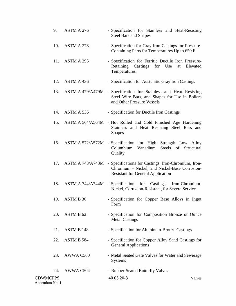
CDWMCPPS 40 05 20-3 Valves
Addendum No. 1
9. ASTM A 276 - Specification for Stainless and Heat-Resisting
Steel Bars and Shapes
10. ASTM A 278 - Specification for Gray Iron Castings for Pressure-
Containing Parts for Temperatures Up to 650 F
11. ASTM A 395 - Specification for Ferritic Ductile Iron Pressure-
Retaining Castings for Use at Elevated
Temperatures
12. ASTM A 436 - Specification for Austenitic Gray Iron Castings
13. ASTM A 479/A479M - Specification for Stainless and Heat Resisting
Steel Wire Bars, and Shapes for Use in Boilers
and Other Pressure Vessels
14. ASTM A 536 - Specification for Ductile Iron Castings
15. ASTM A 564/A564M - Hot Rolled and Cold Finished Age Hardening
Stainless and Heat Resisting Steel Bars and
Shapes
16. ASTM A 572/A572M - Specification for High Strength Low Alloy
Columbium Vanadium Steels of Structural
Quality
17. ASTM A 743/A743M - Specifications for Castings, Iron-Chromium, Iron-
Chromium - Nickel, and Nickel-Base Corrosion-
Resistant for General Application
18. ASTM A 744/A744M - Specification for Castings, Iron-Chromium-
Nickel, Corrosion-Resistant, for Severe Service
19. ASTM B 30 - Specification for Copper Base Alloys in Ingot
Form
20. ASTM B 62 - Specification for Composition Bronze or Ounce
Metal Castings
21. ASTM B 148 - Specification for Aluminum-Bronze Castings
22. ASTM B 584 - Specification for Copper Alloy Sand Castings for
General Applications
23. AWWA C500 - Metal Seated Gate Valves for Water and Sewerage
Systems
24. AWWA C504 - Rubber-Seated Butterfly Valves

CDWMCPPS 40 05 20-4 Valves
Addendum No. 1
25. AWWA C508 - Swing Check Valves for Waterworks Service, 2
inch through 24 inch NPS
26. AWWA C509 - Resilient-Seated Gate Valves for Water Supply
Service
27. AWWA C540 - Power-Actuating Devices for Valves and Sluice
Gates
28. MSS SP-70 - Cast Iron Gate Valves, Flanged and Threaded
Ends
29. MSS SP-71 - Cast Iron Swing Check Valves, Flanged and
Threaded Ends
30. MSS SP-80 - Bronze, Globe, Angle and Check Valves
31. NACM - Welded and Weldless Chain Specifications
32. SAE J356 - Welded Flash Controlled Low-Carbon Steel
Tubing Normalized for Bending, Double Flaring,
and Beading
33. SAE J524 - Seamless Low-Carbon Steel Tubing Annealed for
Bending and Flaring
34. SAE J525 - Welded and Cold-Drawn Low-Carbon Steel
Tubing Annealed for Bending and Flaring
1.3 SUBMITTALS
A. General: Provide all submittals, including the following, as specified in Division
1.
B. Shop Drawings: Submit the following:
1. Complete detailed drawings for all new valves.
2. Complete detailed drawings for all electric motor operators.
3. Complete detailed drawings for refurbished valves, if applicable.
4. Working drawings, including arrangement and erection drawings of the
operators and control equipment; schematic control diagrams, electrical
connection diagrams, and complete description of the control system; and
operating characteristics.

CDWMCPPS 40 05 20-5 Valves
Addendum No. 1
C. Quality Control Submittals: Submit the following:
1. If requested, manufacturer's certified performance and material records.
2. If requested, complete calculations for each size of motor operator indicating
the force required to operate the valve, the operator force provided, full load
and locked rotor current, and horsepower.
D. Operation and Maintenance: Submit operation and maintenance manuals for the
valve operators.
1.4 QUALITY ASSURANCE
A. Furnish all valves of the same type from the same manufacturer. Provide parts that
are interchangeable for all valves of the same type and size.
1.5 DELIVERY, STORAGE AND HANDLING
A. General: Deliver, store and handle all products as specified in Division 1 and as
follows.
B. Storage and Erection: Pack and store all valves in satisfactory operating condition.
Carefully erect all valves in their respective positions, free from all distortion and
strain.
1.6 SPARE PARTS
A. Not used
PART 2 PRODUCT
2.1 MANUFACTURERS
A. Acceptable manufacturers are listed below.
1. Gate Valves:
a. American Flow Control
b. M&H Valve Company
c. Mueller Company
d. Kennedy Valve
e. NIBCO, Inc.
f. Stockham
g. United States Pipe and Foundry
2. AWWA Butterfly Valves:

CDWMCPPS 40 05 20-6 Valves
Addendum No. 1
a. American Flow Control
b. DeZurik
c. Keystone
d. Pratt
3. Single Disc Swing Check Valves:
a. American Flow Control
b. Clow Valve Company
c. M&H Valve Company
d. Mueller Company
4. Solenoid Valves:
a. Automatic Switch Company
b. Magnetrol
c. Versa
d. Midland
5. Globe and Angle Valves:
a. NIBCO, Inc.
b. Stockham
6. Electric Motor Operator - Nonmodulating:
a. Limitorque Corporation
b. Rotork, Inc.
7. Water Hydraulic Actuation and Accumulator System:
a. SunSource, Addison, IL
b. Parco Engineering Corp. (represented by Stonkus Hydraulic,
Bellingham, MA)
2.2 MATERIALS
A. General:
1. Fabricate valves of materials resistant to corrosion for the required service.
2. Unless other materials are needed for corrosion resistance or are specified
elsewhere, fabricate valves that are to be installed in metal pipelines and that
are 2 inches in diameter and smaller of all brass or bronze, except fabricate
the handwheel of ASTM A 197 malleable iron. Fabricate valves that are to
be installed in metal pipelines and that are 2-1/2 inches in diameter and
larger of the materials specified herein.
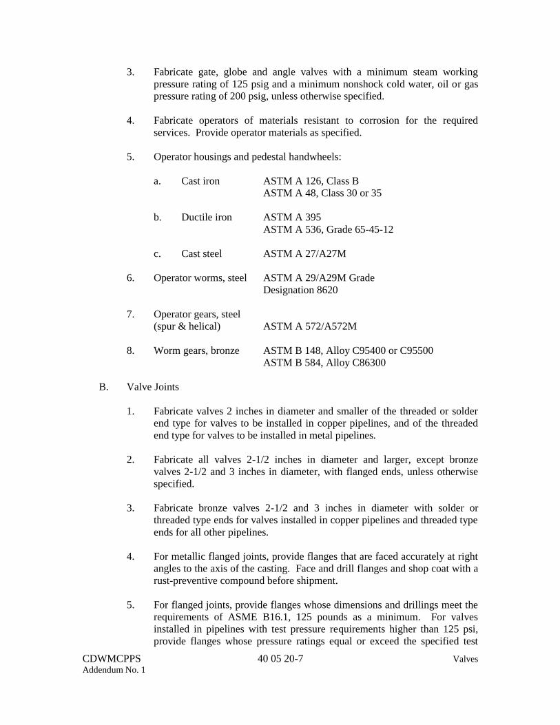
CDWMCPPS 40 05 20-7 Valves
Addendum No. 1
3. Fabricate gate, globe and angle valves with a minimum steam working
pressure rating of 125 psig and a minimum nonshock cold water, oil or gas
pressure rating of 200 psig, unless otherwise specified.
4. Fabricate operators of materials resistant to corrosion for the required
services. Provide operator materials as specified.
5. Operator housings and pedestal handwheels:
a. Cast iron ASTM A 126, Class B
ASTM A 48, Class 30 or 35
b. Ductile iron ASTM A 395
ASTM A 536, Grade 65-45-12
c. Cast steel ASTM A 27/A27M
6. Operator worms, steel ASTM A 29/A29M Grade
Designation 8620
7. Operator gears, steel
(spur & helical) ASTM A 572/A572M
8. Worm gears, bronze ASTM B 148, Alloy C95400 or C95500
ASTM B 584, Alloy C86300
B. Valve Joints
1. Fabricate valves 2 inches in diameter and smaller of the threaded or solder
end type for valves to be installed in copper pipelines, and of the threaded
end type for valves to be installed in metal pipelines.
2. Fabricate all valves 2-1/2 inches in diameter and larger, except bronze
valves 2-1/2 and 3 inches in diameter, with flanged ends, unless otherwise
specified.
3. Fabricate bronze valves 2-1/2 and 3 inches in diameter with solder or
threaded type ends for valves installed in copper pipelines and threaded type
ends for all other pipelines.
4. For metallic flanged joints, provide flanges that are faced accurately at right
angles to the axis of the casting. Face and drill flanges and shop coat with a
rust-preventive compound before shipment.
5. For flanged joints, provide flanges whose dimensions and drillings meet the
requirements of ASME B16.1, 125 pounds as a minimum. For valves
installed in pipelines with test pressure requirements higher than 125 psi,
provide flanges whose pressure ratings equal or exceed the specified test

CDWMCPPS 40 05 20-8 Valves
Addendum No. 1
pressure of the pipeline. Furnish special drillings where required. For
valves having flanges that do not conform with the thickness requirements
of ASME B16.1, test each valve in accordance with the hydrostatic shell test
pressure requirements of ASME B16.1.
C. Operating Force: Fabricate valves to limit the maximum force required to operate
all manual valves, including but not limited to valves with wrench operated nuts,
levers, handwheels and chainwheels, to 40 pounds. Limit the overall length of
each wrench or single-arm lever to 18 inches. Limit the overall length of each
dual-arm lever to 36 inches.
D. Handwheel: Mark each valve handwheel with an arrow and the word OPEN.
Mark each nut with an arrow.
E. Manually Operated Valves: Equip all manually operated valves that have
operating nuts, levers or handwheels and that are more than 7 feet above the floor
with chain operated levers or chainwheels. Extend chains to 7 feet above the floor.
2.3 GATE VALVES
A. Materials: Unless otherwise shown or specified, furnish and install gate valves
meeting the following requirements:
Nominal Valve Size, Inches Standard Type
16 and larger, except for HVAC Service AWWA C500 Double disc
B. Non-rising Stem: Equip non-rising stem valves, except for buried or submerged
service, with externally visible indication of the disc position at all points of travel.
C. Stem Seals: Use the following types of stem seals:
Valve Type Stem Seal
Geared Non-rising stem O-ring or stuffing box
D. Packing: Provide non-asbestos braided, twisted or formed ring type packing
suitable for the pressure-temperature ratings of the valve.
E. Bonnet: Provide 4-inch and larger gate valves with outside screw and yoke
bonnets.
F. Accessories: Provide zinc plated bonnet bolts, studs and nuts except for
submerged service. Provide stainless bonnet bolts, studs and nuts for submerged
service. Make wedging devices bronze to iron or bronze to bronze. Provide
glands which are bronze or bronze bushed and bronze gland bolts and nuts.

CDWMCPPS 40 05 20-9 Valves
Addendum No. 1
G. SV-1B and SV-2B: Provide non-rising stem double disc or rotating disc, NSF-61
certified gate valves without bypass valve.
2.4 BUTTERFLY VALVES
A. General:
1. Provide butterfly valves 4 inches and smaller of the full lug pattern with
drilled and tapped bolt holes.
2. Provide butterfly valves 6 inches and larger of the full flanged pattern that
meet the requirements of AWWA C504.
3. Provide butterfly valves of the rubber-seated, tight-closing type.
4. For fluid temperatures equal to or less than 180 degrees F, provide Buna-N
seats. For fluid temperatures greater than 180 degrees F, provide EPDM or
Viton seats. For fluid temperatures exceeding the temperature ratings of
EPDM and Viton, provide seats that are appropriate for the intended service.
B. Materials:
1. For butterfly valves 4 inches and smaller, provide valve materials as
specified below or as required for the service.
a. Valve bodies:
Cast iron ASTM A 126, Class B
b. Valve shafts:
Stainless steel ASTM A 564, Type 630 (17-4 PH stainless
steel)
ASTM A 276 Grade 316
c. Valve discs:
Aluminum Bronze ASTM B 148
Bronze ASTM B 30
d. Bearings: TFE coated stainless steel
2. For butterfly valves 6 inches and larger, provide valve materials as specified
below or as required for the service:
a. Valve bodies:
Cast iron ASTM A 126, Class B
ASTM A 48, Class 40
b. Valve shafts: ASTM A 276 or A 479/A479M, Type 304,
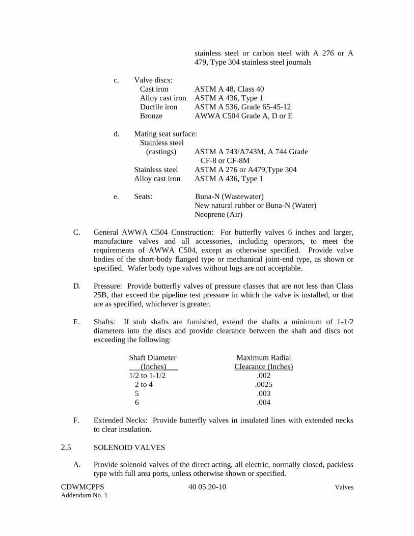
CDWMCPPS 40 05 20-10 Valves
Addendum No. 1
stainless steel or carbon steel with A 276 or A
479, Type 304 stainless steel journals
c. Valve discs:
Cast iron ASTM A 48, Class 40
Alloy cast iron ASTM A 436, Type 1
Ductile iron ASTM A 536, Grade 65-45-12
Bronze AWWA C504 Grade A, D or E
d. Mating seat surface:
Stainless steel
(castings) ASTM A 743/A743M, A 744 Grade
CF-8 or CF-8M
Stainless steel ASTM A 276 or A479,Type 304
Alloy cast iron ASTM A 436, Type 1
e. Seats: Buna-N (Wastewater)
New natural rubber or Buna-N (Water)
Neoprene (Air)
C. General AWWA C504 Construction: For butterfly valves 6 inches and larger,
manufacture valves and all accessories, including operators, to meet the
requirements of AWWA C504, except as otherwise specified. Provide valve
bodies of the short-body flanged type or mechanical joint-end type, as shown or
specified. Wafer body type valves without lugs are not acceptable.
D. Pressure: Provide butterfly valves of pressure classes that are not less than Class
25B, that exceed the pipeline test pressure in which the valve is installed, or that
are as specified, whichever is greater.
E. Shafts: If stub shafts are furnished, extend the shafts a minimum of 1-1/2
diameters into the discs and provide clearance between the shaft and discs not
exceeding the following:
Shaft Diameter
(Inches)___ Maximum Radial
Clearance (Inches) 1/2 to 1-1/2 .002 2 to 4 .0025 5 .003 6 .004
F. Extended Necks: Provide butterfly valves in insulated lines with extended necks
to clear insulation.
2.5 SOLENOID VALVES
A. Provide solenoid valves of the direct acting, all electric, normally closed, packless
type with full area ports, unless otherwise shown or specified.

CDWMCPPS 40 05 20-11 Valves
Addendum No. 1
B. Design valves to not require a pressure assist from the process fluid to open or
close. Size the solenoids in accordance with the pressure conditions in the pipeline
in which valves are installed.
C. Construct the valve body and bonnet of forged brass and construct the solenoid
core of stainless steel.
D. Design solenoid the coils for 115-volt, 60-hertz operation. Embed solenoid coils
in molded plastic and install coils in NEMA Type 1 general purpose enclosures,
DIN plug connections preferred for service without unwiring connections except
as shown or specified.
2.6 CONTROL VALVES
A. Provide 4-way, differential-operated, packless, poppet seat type solenoid-operated
control valves with all parts rustproof and non-corrosive. Provide coils of the
molded type, Class B insulated, in NEMA Type 4 Enclosure for nonhazardous
areas, designed for operation using 120-volt, 60-hertz current. Provide single-
solenoid type valves. Arrange the solenoid such that when energized it positions
the 4-way valve to open the cylinder-operated valve and when de-energized, it
positions the 4-way valve to close the cylinder-operated valve. Arrange the 4-way
valves for manual operation independent of and without disturbing the electrical
control. Provide emergency close function with additional single solenoid valve
which overrides any other function or operation that may be in process.
2.7 GLOBE AND ANGLE VALVES
A. General: Provide globe and angle valves that meet the requirements of MSS SP-
80.
B. Disc and Seats: Equip gate and globe valves with renewable bronze discs and
renewable seats.
C. Bonnet: Equip globe and angle valves with threaded bonnets.
D. Packing: Provide non-asbestos braided, twisted or formed ring type packing
suitable for the pressure-temperature ratings of the valve.
2.8 BALL VALVES
A. In accordance with Section 22 10 00.
2.9 BACKFLOW PREVENTERS
A. In accordance with Section 22 10 00.

CDWMCPPS 40 05 20-12 Valves
Addendum No. 1
2.10 MANUAL BUTTERFLY VALVE OPERATORS
A. General: Provide operators as an integral part of the valve. Manufacture manual
operators of the enclosed, hand-lever, traveling-nut or worm-gear type, as shown
or specified.
B. Hand-Lever Type: Fabricate hand-lever type operators of cast-iron or steel
construction with a nonmetallic, nonslip handgrip. Equip the lever with a locking
device to secure the valve disc in the fully open or fully closed position, or at a
minimum of 5 intermediate positions at 15 degree intervals. Provide mechanical
stop-limiting devices to prevent overtravel of the disc in either direction.
Permanently lubricate operators or provide operators with grease fittings.
C. Traveling-Nut Type: Fabricate traveling-nut type operators with a threaded steel
screw and a bronze nut. Provide a slotted-lever or link-lever system to transfer the
applied torque to the disc shaft. Equip all rotating shafts, screws and links with
separate bearings. Provide thrust bearings.
D. Worm-Gear Type: Fabricate worm-gear type operators with a worm gear and
matching drive worm. Provide bearings for each rotating member.
E. Stop-Limiting Devices: Provide stop-limiting devices on traveling-nut and
worm-gear type operators to prevent overtravel of the disc in either direction.
Design the operator to hold the disc in any position without flutter or wear on the
valve or operator. House the operator in a watertight enclosure. Pack operators
with grease or with oil. For buried or submerged service, equip valve operators
with stainless steel external bolting.
F. Position Indicators: For buried or submerged service, equip manually operated
butterfly valves, with externally visible indication of the disc position.
2.11 ELECTRIC MOTOR OPERATORS – NON-MODULATING
A. Provide electric motor operators for the following valves:
1. Existing isolation discharge valve: DV-1, DV-2, DV-3, DV-4, and DV-5
2. Existing isolation suction valve: SV-3, SV-4, and SV-5
3. New isolation suction valve: SV-1B and SV-2B
B. General: Provide non-modulating electric motor operators of the close-coupled,
electric motor-driven, worm gear type, complete with motor, gearing, limit
switches and auxiliary contacts, torque switches, position indicator, handwheel,
integral controller, and all required appurtenances. Design the operators to rotate
valve discs through 90 degrees from the fully open to the fully closed position and
back, as in butterfly, ball valves, lift gate discs from the fully closed to the fully
open position and back, as in gate valves. Provide operators that hold the discs in
any position from fully open to fully close without vibration.
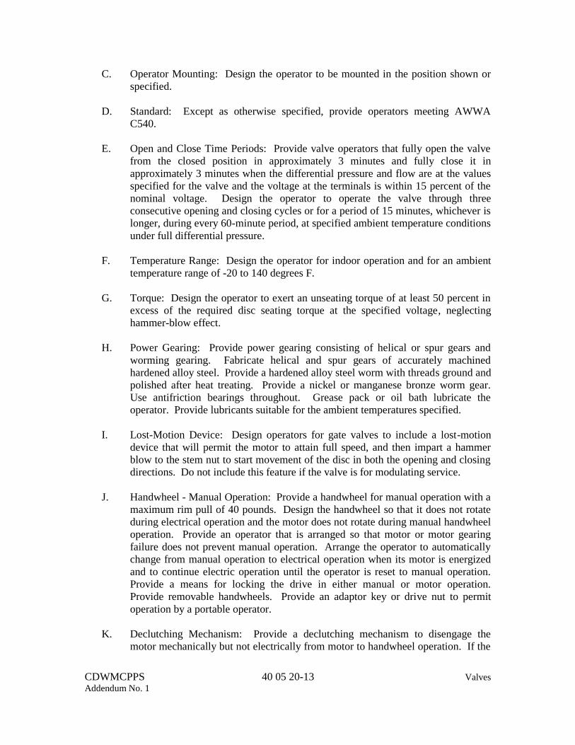
CDWMCPPS 40 05 20-13 Valves
Addendum No. 1
C. Operator Mounting: Design the operator to be mounted in the position shown or
specified.
D. Standard: Except as otherwise specified, provide operators meeting AWWA
C540.
E. Open and Close Time Periods: Provide valve operators that fully open the valve
from the closed position in approximately 3 minutes and fully close it in
approximately 3 minutes when the differential pressure and flow are at the values
specified for the valve and the voltage at the terminals is within 15 percent of the
nominal voltage. Design the operator to operate the valve through three
consecutive opening and closing cycles or for a period of 15 minutes, whichever is
longer, during every 60-minute period, at specified ambient temperature conditions
under full differential pressure.
F. Temperature Range: Design the operator for indoor operation and for an ambient
temperature range of -20 to 140 degrees F.
G. Torque: Design the operator to exert an unseating torque of at least 50 percent in
excess of the required disc seating torque at the specified voltage, neglecting
hammer-blow effect.
H. Power Gearing: Provide power gearing consisting of helical or spur gears and
worming gearing. Fabricate helical and spur gears of accurately machined
hardened alloy steel. Provide a hardened alloy steel worm with threads ground and
polished after heat treating. Provide a nickel or manganese bronze worm gear.
Use antifriction bearings throughout. Grease pack or oil bath lubricate the
operator. Provide lubricants suitable for the ambient temperatures specified.
I. Lost-Motion Device: Design operators for gate valves to include a lost-motion
device that will permit the motor to attain full speed, and then impart a hammer
blow to the stem nut to start movement of the disc in both the opening and closing
directions. Do not include this feature if the valve is for modulating service.
J. Handwheel - Manual Operation: Provide a handwheel for manual operation with a
maximum rim pull of 40 pounds. Design the handwheel so that it does not rotate
during electrical operation and the motor does not rotate during manual handwheel
operation. Provide an operator that is arranged so that motor or motor gearing
failure does not prevent manual operation. Arrange the operator to automatically
change from manual operation to electrical operation when its motor is energized
and to continue electric operation until the operator is reset to manual operation.
Provide a means for locking the drive in either manual or motor operation.
Provide removable handwheels. Provide an adaptor key or drive nut to permit
operation by a portable operator.
K. Declutching Mechanism: Provide a declutching mechanism to disengage the
motor mechanically but not electrically from motor to handwheel operation. If the

CDWMCPPS 40 05 20-14 Valves
Addendum No. 1
clutch is of the external lever type, arrange it such that the lever does not move
when the motor is energized.
L. Position Indication: Provide an operator-mounted disc position indicator of
indicating light type. For OPEN-CLOSED service, indicate the fully open, fully
closed and intermediate disc position by lights. For modulating or throttling
service, provide continuous disc position indication between the fully open and
fully closed positions. Provide electrical contacts as required for remote indication
of disc position.
M. Electric Motor Design: Provide an operator motor of the high torque, ball or roller
bearing, squirrel-cage type designed for continuous valve duty. Provide motor
rated for 15 minute duty cycle or three complete opening and closing valve
strokes, whichever is longer, during a 60 minute period under full differential
pressure at 40 degrees C ambient. Design the motor for use on a nominal 480
volts, 3-phase, 60-hertz electrical service. Provide motor windings and leads with
Class F or better insulation with built-in thermal overload protection. In other
respects, provide motors meeting the requirements of Section 26 20 10.
N. Housing: Provide housings for controls, gears, and motors with integrally cast
flanges. Fully machine and template drill the flanges and their mating surfaces.
Provide joints which are metal-to-metal or gasket or O-ring sealed as required.
O. Control and Motor Enclosures: Provide NEMA 4 control and motor enclosures,
except as otherwise specified. Provide the controller with mechanical interlocks
and mount as an integral part of the operator.
P. Electrical Compartment Heater: Provide electrical compartment heaters, unless
other means can be proven effective for moisture elimination.
Q. Electrical Requirements: Provide electrical controls for the operator as shown or
specified. Design operators for 208-volt, 3-phase, 60-hertz service for DV-1, DV-
2, DV-3, DV-4, and DV-5. Design operators for 480-volt, 3-phase, 60-hertz
service for SV-1B, SV-2B, SV-3, SV-4, and SV-5. Design all control circuits for
120-volt, single-phase, 60-hertz ac. Provide an integral control transformer with
fused secondary.
R. Reversing Controller, Overload Protection and Internal Wiring: Provide a NEMA
rated reversing controller, or an approved special duty rated reversing controller,
complete with mechanical interlocks and controls as an integral part of the
operator. Provide adequate overload protection in the controller or embedded in
the motor windings. Install an overload device in each phase. If overload devices
are installed in the motor windings, provide devices of the bimetallic automatic
reset type with the contacts in the control circuit. Arrange the internal wiring in
the operator so that the opening and closing coils cannot be energized
simultaneously at any time, regardless of external wiring conditions.

CDWMCPPS 40 05 20-15 Valves
Addendum No. 1
S. Push Buttons and Selector Switches: Where operators are 7 feet or closer to the
floor and in an accessible location, mount OPEN- STOP-CLOSE push buttons or a
selector switch as shown on the operator housing. Also mount red and green
position indicator lights and, where shown or required, an amber ready light or
MANUAL-AUTO mode selector on the operator housing. Where the operators
are located over 7 feet from the floor or in an inaccessible location, connect all
internal control and indication wiring to a terminal block within the operator
enclosure and provide a separate control station for remote mounting. Provide the
remote control station with the same NEMA rating as the operator.
T. Limit and Torque Switches: Provide the operator with limit and torque switches,
either direct or gear driven. Provide adjustable limit and torque switches with
auxiliary contacts that are operative in either direction of travel. Provide limit
switches that are "in step" with torque switches at all times, whether in motor or
manual operation. Equip the operator with limit switches to stop movement in
each direction and torque switches for protection against mechanical overload and
to stop movement in either direction if an obstruction is encountered. Provide the
number, function and arrangement of limit switches as shown, specified or
required.
1. Provide the following limit switches for all existing check valves and
existing discharge valves:
a. NEMA 4X enclosure
b. Visual Indicator
c. Captive Cover Bolts
d. Mechanical SPDT
e. Quick Set Spring loaded cam.
f. Manufacturers:
(1) A-T Control
(2) DeZurik
2. All limit Switches shall be wired to SCADA system as shown on P&IDs
U. Additional Accessories:
1. Provide additional limit switches, indicating lights, position transmitters and
remote position indicators, remote operating controls and other accessories
and controls as shown, specified or required.
2. Provide position transmitters for all existing check valves, existing discharge
valves, and suction valves (new and existing):
a. NEMA 4X enclosure
b. Epoxy Coated
c. Settings: Less than 1 degree
d. 4-20ma Signal

CDWMCPPS 40 05 20-16 Valves
Addendum No. 1
e. 24 VDC Power Supply
f. Manufacturers:
(1) A-T Control
(2) Dezurik
g. All position transmitters shall be wired to SCADA system as shown
on P&IDs
V. Control Components, Operator Housing and Operator Wiring: Provide control
components and operator housing that meets the requirements of Section 26 05 60.
Provide operator wiring that meets the requirements of Section 26 05 19.
2.12 WATER HYDRAULIC ACTUATION AND ACCUMULATOR SYSTEMS
A. System includes:
1. Two hydraulic accumulator systems
2. Five hydraulic actuation systems (one per pump discharge check valve)
3. Piping and controls for each check valve
B. Each hydraulic accumulator system includes:
1. One hydropneumatic tank
2. Two hydraulic water pumps
3. Two air compressors
4. One system control panel
5. Switches, valves, gauges, and all accessories for a complete operable system
C. Each hydraulic actuation system includes:
1. One valve control panel
2. Switches, valves, gauges, and all accessories for a complete operable system
D. Each hydraulic accumulator system shall supply water under hydropneumatic tank
design pressures of approximately 100 psig minimum and 150 psig maximum.
Each assembly and piping system shall provide a minimum of 200 gallons of water
under pressure to the valves for one complete stroke for emergency closure
without operations of the water pumps or air compressors, on power failure.
E. Each hydraulic accumulator unit shall be provided with a fabricated steel base
which extend beyond each end of the assembly and be equipped with mounting
holes. Lifting eyes shall be provided for each assembly to permit loading,
unloading, and moving of the unit. The entire assembly shall be provided as a
complete, self-contained unit with all components factory piped and wired, except
for the tanks where field connection between the tanks and the mechanical
equipment is acceptable. It must be capable of being disassembled for repair
and/or replacement.

CDWMCPPS 40 05 20-17 Valves
Addendum No. 1
F. Hydropneumatic Tank
1. Construct tank in accordance with ASME Boiler and Pressure Vessel Code,
Section VIII, Division I, for Unfired Pressure Vessels.
2. Vertical configuration
3. Design each tank for a maximum working pressure of 175 psig
4. Design each tank to handle all five check valves operation at any one time
under emergency condition.
5. Test tank under 1.5 times the maximum working pressure. Test shall be
performed after assembly, but before painting, with all openings closed.
Continuously test tank until all seams and joints have been demonstrated to
be thoroughly tight. All of the necessary equipment, material, and labor
must be furnished for conducting the test. Stamp tank to show compliance
with ASME code.
6. Provide the following for each tank:
a. Pressure relief valve
b. Sight gauge with shutoff cocks
c. Drain line with valve
d. Piping connections
e. Pressure switch connections
f. Level switches
g. Gauges, pressure switches, pressure regulators, level switches, and
other field instrumentation and appurtenances for a complete operable
system. Provide field instrumentation in accordance with Section 40
91 00.
G. Hydraulic Water Pumps
1. Type: Positive displacement, single vane type.
2. Capacity: 20 gpm at 200 psi maximum pressure
3. Motor: 10 Hp. Horizontal shaft, totally enclosed, fan cooled, squirrel-cage
induction motor. Rated at 460 V, 3 Phase, 60 Hz. In accordance with
Section 26 20 10.

CDWMCPPS 40 05 20-18 Valves
Addendum No. 1
H. Air Compressors
1. Type: Two-stage, reciprocating, single acting, air-cooled
2. Capacity: 17 SCFM at 175 psi maximum pressure
3. Motor: 5 Hp, 480 V, 3 Phase, 60 Hz. In accordance with Section 26 20 10.
I. Valve Control Panels
1. Provide a total of five (5) valve control panels, one valve control panel for
each pump check valve.
2. The valve control panel shall be an integrated design, furnished by one
manufacturer who shall provide all of the equipment and accessories, and
shall be incorporated with the hydraulic actuation system. The manufacturer
shall be responsible for the satisfactory operation of the entire system.
Solenoid Control Valves prewired to terminal box for interface with Pump
operation. See #6 below.
3. Steel components must be painted gray epoxy over epoxy primer.
4. External hardware: bright nickel or chromium plated
5. Nameplate: engrave plastic or metal
6. Termination enclosure needed for prewiring solenoid valves for interface to
the process pump controller panel.
7. Valve control system shall have the ability for manual operation of the pump
outlet manually as long as pressurized fluid is available. Isolation valves
and manual operators for control valves as needed.
8. Provide all auxiliary devices required for the control equipment. All
hydraulic devices shall be internally piped to pressure, drain and (2) cylinder
connections. All hydraulic hose shall be fitted with female swivel ends. All
soldered joints shall be made of solid silver wire solder of 95 percent tin and
5 percent antimony. Electrical devices shall be wired to a numbered terminal
block in the panel.
9. Mount the control panel on a floor stand. Provide a valved water supply
pressure connection to the panel drain from the panel and two connections
between the panel and the hydraulic cylinder on the valve operator. All
piping shall be type K hard copper sized by the manufacturer with all joints
soldered.
10. The control system shall operate each pump check valve as follows based
upon inputs received from the process pumps controller:

CDWMCPPS 40 05 20-19 Valves
Addendum No. 1
a. When the pump is not operating, the valve must remain close.
b. When the pump is energized, the control valve shall start to open at a
uniform rate. The control valve’s opening time shall be field
adjustable from 15 to 150 seconds, with an initial setting at 30
seconds.
c. In the event of a power failure or Emergency Stop conditions as
specified in Section 40 90 50, the check valve shall close rapidly and
the speed of closure shall be independently adjustable from 10 to 30
seconds with an initial setting at 15 seconds.
J. Water Supply to Accumulators
1. Supply water to the hydraulic accumulator systems from a non-potable
water system as shown on Contract Drawings.
2. Feed the supply directly into the hydraulic accumulator system water pumps,
providing a flooded suction at all times.
3. An automatic shut-off is required on the hydraulic water pumps feed to the
accumulator to prevent over filling from source water pressure once hydro-
pneumatic tank is full.
K. Valves
1. Provide valves in accordance with this section.
2. Hydraulic Actuation System Valve Control Panels: Provide an additional
speed control valve for emergency close cycle. Provide solenoid valves
rated 120 V AC for normal close operation and emergency close operation.
Provide the control valve, needle valve type, with a calibrated adjusting
knob and constructed of brass or stainless steel materials.
3. Operate the directional valves at a hydraulic water pressure of 60 psig
minimum and 150 psig maximum.
L. Field Instrumentations for Hydraulic Actuation System Valve Control Panels:
1. Provide gauges in accordance with Section 40 91 00.
2. Pressure gauge for each check valve control system: Provide gauges with a
minimum of 4-1/2 inch diameter dial plainly marked and 1/2- inch NPT
bottom connection. Connect the gauges with brass pipe, fittings and
isolating stopcocks. The scale range of each gauge must be 0 to 300 psig.
3. Gauges shall be in accordance with ANSI B40.1 Grade 2A. The bourbon
tube shall be of bronze construction. The case shall be black phenolic with
clear acrylic window. Gauges shall have provision for zero adjustment.

CDWMCPPS 40 05 20-20 Valves
Addendum No. 1
4. All fittings must be brass, copper, or stainless steel.
5. Provide full open and full close limit switches for each check valve.
6. Provide differential pressure switch. The differential pressure switch shall
be piped across the check and the discharge valve.
M. Hydraulic Piping
1. Piping installation: In accordance with Section 22 10 00.
2. Piping support: In accordance with Section 40 05 01.
3. Water Piping: For 1 inch and smaller, Type K copper tubing soldered with
95/5 solder. The central system piping, as well as extensions to each pump
shall be tested at 215 psig for 1 hour.
4. Air Piping: Stainless steel.
N. Shop Painting
1. Interior of hydropneumatic tank: sandblasted and painted.
2. Exterior of hydropneumatic units: painted grey epoxy over an epoxy primer.
3. Provide painting in accordance with Section 09 96 00.
O. System Controls for Hydraulic Accumulator Systems
1. Control system shall be PLC based. Provide PLC system conforming to
Section 40 94 43.
2. Provide Ethernet connection to the Pumping Station Local Area Network
through Network Access Panel (by others).
3. Provide the tag names and/or registers of the signals to be monitored by the
SCADA system to the System Integrator.
4. Provide a NEMA 12 painted steel control panel containing the necessary
main circuit breaker, motor circuit protectors, motor starting contactors for
the air compressor motors and the hydraulic pump motors, transformers,
reset buttons, hand-off-automatic selector switches, LED type pilot lights,
control relays, terminal strips, pressure gauge, pressure switches, and any
additional equipment necessary by the manufacturer for proper operation of
the system. Provide an adequately sized single power feed to each control
panel at 480 V AC for power to the entire hydraulic accumulator system.
Provide control panel and equipment in accordance with Section 40 94 43.
Provide all process control instrumentation in accordance with Section 40 91
00.

CDWMCPPS 40 05 20-21 Valves
Addendum No. 1
5. The hydraulic pumps shall work alternately with a lead/lag circuit in such a
manner that if the lead pump fails to properly fill the accumulator tank, and
level continues to drop, the lag pump shall run to fill the accumulator tank.
A local, visual alarm with manual reset shall indicate operation of the lag
pump. If a pump fails to start, a pump failure alarm shall be transmitted to
the SCADA.
6. Pump “ON” status shall be transmitted to SCADA.
7. The air compressors shall operate in an alternating lead/lag circuit in such a
way that if the lead compressor is unable to build air pressure within the
pressure tank, the lag compressor shall be started. A local, visual alarm with
manual reset shall indicate operation of the lag air compressor. Each air
compressor “ON” status shall be transmitted to SCADA.
8. Provide fluid level control devices for each accumulator tank. Accumulator
low air pressure and low level alarms shall be transmitted to SCADA.
9. Provide sight gages with shutoff cocks to show the water level in the
accumulator tank.
P. Accessories
1. Provide drain lines and dirt pockets to collect foreign matter with cleanout
facilities.
2. Provide all necessary safety valves, strainers, pressure gauges and pressure
switches in accordance with Section 40 91 00 for proper system operation.
Q. Prior to shipping the systems, conduct a shop test that demonstrates that the unit
fulfills the operating requirements of the Specifications.
R. Upon completion of installation, provide service of a qualified field service
engineer to inspect the installation, place the equipment in service, and instruct
City’s personnel in the proper operation, care and maintenance of the equipment.
Schedule the startup and training service with the Commissioner after the system is
completely installed and ready for start up.
2.13 RECORD EXISTING INFORMATION PRIOR TO INSPECTION OF THE
CHECK VALVES AND DISCHARGE VALVES
A. Record all existing field information prior to disturbing pumps and valves. This
field information will be presented to the Commissioner for approval.
B. Include the following within the field information:
1. Pressure differentials upstream and downstream of valve

CDWMCPPS 40 05 20-22 Valves
Addendum No. 1
2. Supply pressure to the hydraulic cylinders (if applicable)
3. Opening and closing times (normal condition)
4. Closing time (emergency condition)
5. Orientation of valve, torque unit, and location of controls
2.14 INSPECTION, TESTING AND REPORTING ON CONDITION OF CHECK
VALVES CV-1, CV-2, CV-3, CV-4, CV-5 AND DISCHARGE VALVES DV-1,
DV-2, DV-3, DV-4 AND DV-5
A. Perform the following prior to inspection and testing of the valves:
1. Perform Work in accordance with Section 01 12 16.
2. Remove and abate the discharge piping insulation prior to removal of the
pump or inspection of the Pump discharge valve.
3. Close the pump’s corresponding suction valve, remove the Main Pump and
cap the suction inlet with a blind flange.
4. Coordinate with the City to locate and close the associated distribution
valve/s located on Fillmore Street and Central Park Avenue. All valves
outside of the Pump Station shall be operated (opened and closed) by the
City.
5. Prepare the project site for any leakage during the test such that the station
is not flooded.
B. Inspection and Testing of the Check and the Discharge Valves:
1. Inspection of the Check Valves (when not under pressure)
a. Close the associated Pump discharge valve.
b. Close the associated distribution valves.
c. Drain the pipe in between the check valve and the Pump discharge
valve.
d. Operate the check valve with the existing actuation cylinder 10
times and note for any abnormalities in open or close operation.
e. Inspect the valve, visible seating surfaces, operator, and linkage
components, if feasible, prior to installation of blind flange.
2. Leakage Testing of the Check Valves (under pressure): Perform leakage test
upon completion of the inspection of the check valve as follows:

CDWMCPPS 40 05 20-23 Valves
Addendum No. 1
a. Close the check valve.
b. Open the Pump discharge valve.
c. Open the distribution valve.
d. Fill the discharge pipe with water.
e. Measure leakage through the valve against header pressure for 10
minutes or until 50 gallons has leaked.
f. Repeat the leakage test three (3) times.
g. In between testing, close the Pump discharge valve and empty the
water in between Pump discharge and check valve by opening the
check valve and then reclose the check valve for testing.
3. Inspection of the Pump Discharge Valve (when not under pressure)
a. Open the check valve.
b. Close the distribution valve.
c. Drain the pipe in between the Pump discharge valve and the
distribution valve.
d. Operate both check and discharge valve 10 times and note for any
abnormalities in open or close operation.
4. Leakage Testing of the Pump Discharge Valves (under pressure): Perform
leakage test upon completion of the inspection of the Pump discharge valve
as follows:
a. Open the check valve.
b. Close the Pump discharge valve.
c. Open the distribution valve/s.
d. Fill discharge pipe in between the Pump discharge valve and the
distribution valve with water.
e. Measure leakage through the valve against header pressure for 10
minutes or until 50 gallons has leaked.
f. Repeat the leakage test three (3) times.
C. Reporting on the Inspection and Testing of the Check and the Pump Discharge
Valves: Submit a certified report on each valve by a company that is a member of

CDWMCPPS 40 05 20-24 Valves
Addendum No. 1
the Valve Repair Council of the Valve Manufacturers of America. The report at a
minimum to include the following:
1. Existing field information listed within 2.13.B with pictures.
2. Abnormalities in open and close operation.
3. Inspection of the valve, visible seating surfaces, operator and linkage
components.
4. Leakage test procedures and test data.
5. Recommendations for refurbishment that include refurbishment procedures,
materials, and costs associated with the refurbishment and a schedule.
6. Recommendations for replacement that include the conditions of the valve
are non-repairable, replacement options, costs and a schedule.
7. Submit 10 copies of the report to the Commissioner. The refurbishment and
replacement of a valve will commence upon an acceptance and approval of
the scope of work from the Commissioner.
PART 3 EXECUTION
3.1 EXAMINATION
A. Examine piping system for compliance with requirements for installation
tolerances and other conditions affecting performance of valves. Proceed with
installation until unsatisfactory conditions have been corrected.
B. Examine valve interior for cleanliness, freedom from foreign matter and corrosion.
Remove special packing materials such as blocks that are used to prevent
movement during shipping and handling.
C. Examine threads on valve and mating pipe for form and cleanliness.
D. Examine mating flange faces for conditions that might cause leakage. Check
bolting for proper size, length, and material. Check gasket material for proper size,
material composition suitable for service, and freedom from defects and damages.
3.2 INSTALLATION
A. General: Install valves as indicated on Drawings, in accordance with the
manufacturer's recommendations approved shop drawings and as specified in
Division 1.
B. Install valves with unions or flanges at each piece of equipment at an orientation to
allow servicing, maintenance, and equipment removal without system shutdown.

CDWMCPPS 40 05 20-25 Valves
Addendum No. 1
C. Install valves in a position to allow full stem movement.
D. Install valves in horizontal piping with stem at or above the center of the pipe.
E. Locate valves for easy access and provide separate support where necessary.
3.3 REFURBISHING OF CHECK VALVES CV-1, CV-2, CV-3, CV-4, CV-5 AND
DISCHARGE VALVES DV-1, DV-2, DV-3, DV-4 AND DV-5
A. Perform Work in this section only if the valve is approved for off-site refurbishment
by the Commissioner.
B. Upon approval to refurbish a check or discharge valve off site, provide blind
flanges as required to prevent water leakage into the Pumping Station.
C. Shipment of the valves:
1. Check the valve for any hazardous waste prior to removal from line and
remediate valve if necessary for hazardous substances.
2. Disconnect valve from piping and prepare for shipment by completing the
following:
a. Drain the water from the valve.
b. Close the valve
3. Package the valve for transport to the refurbishment facility in a manner that
no damages are incurred during transportation of the valve or any
components to or from the refurbishment facility.
D. Inspection:
1. Perform the following procedures on the valves and include within the
inspection report:
a. Identify each part by stamp or etching.
b. Document the following with photographs:
(1) Condition of the existing bushings and journals.
(2) Condition of the shaft nut threads.
(3) Condition of the lift/operating shaft along wear seal area –
looking for washout, wear, or galling.

CDWMCPPS 40 05 20-26 Valves
Addendum No. 1
(4) Metal seats – provide touch up weld, machine, and regrind
surface to meet AWWA C507 requirements.
(5) Resilient seals such as o-rings, seals, or v-packing.
c. Shaft:
(1) Remove the shafts and set-up on V blocks.
(2) Inspect the shaft by using a dial indicator.
(3) Measure using a micrometer, measure all of the various sizes
used to locate the associated parts found on the shaft. Note
these sizes on the shaft profile shop drawing.
E. Inspection Report: Prepare a written inspection report, complete with photographs
of “as received” condition, for each element. Include results of the inspection
along with recommendations to restore the element to like new condition, the cost
for refurbishment, and a schedule in the report. Include discussion of any special
procedure such as weld repair.
F. Factory Witness Test and Inspection
1. For witness test and inspection requirements refer to Section 26 05 10.
2. The Commissioner will witness test and inspect the valves and all
components. Provide the Commissioner with 10 sets of certified factory
inspection reports (reports must include complete test procedures and all
Work proposed for the valve and its components). The Commissioner will
conduct an onsite inspection to verify the result of the inspection report.
These certified factory inspection reports and test procedures will be
reviewed and accepted by the Commissioner prior to scheduling the factory
visit date. Provide the Commissioner with the factory testing date in writing.
Provide a minimum of two weeks advance notice prior to the factory test.
3. Complete the factory witness inspection for each valve in one trip.
G. Refurbishment
1. Replace the bushings and journals.
2. Replace all resilient seats.
3. Replace shafts and nuts if necessary.
4. Using vertical lathe, machine off existing weld on seats on both body and
ball/cone.
5. Weld on new seat material, using no lead in process.

CDWMCPPS 40 05 20-27 Valves
Addendum No. 1
6. Machine rough cut and grind new seats on cone/ball and body.
7. Repaint valve body, torque unit, and cylinder.
8. Reassemble valve, torque unit, and cylinder and test valve per AWWA
C507 requirements.
9. Provide for Witness Test and inspection at factory and record and submit
witness test for approval.
10. Provide final paint coat and ship to Pumping Station for Contractor to
reinstall.
H. Payment: Additional refurbishments so authorized in writing by the
Commissioner will be paid as a change order.
3.4 PAINTING AND COATING
A. General: Unless otherwise specified, coat the inside iron or steel surfaces of all
valves and exterior surfaces of valves and operators that are to be buried in the
ground or immersed in water with two coats of asphalt varnish. Paint exterior
surfaces of other valves and operators as specified in Section 09 96 00.
3.5 FIELD QUALITY CONTROL
A. Manufacturer's Field Services: Furnish the services of a qualified representative of
each of the various manufacturers to provide instruction on the proper installation
of the equipment, inspect the completed installation, make any necessary
adjustments, participate in the startup of the equipment, participate in the field
testing of the equipment, and place the equipment in trouble-free operation, as
specified in Division 1.
B. Tests: After installation of the valves, control equipment and all appurtenances,
subject the units to a field running test, as specified in Division 1, under actual
operating conditions. Operate each valve through one complete open-close cycle
under the maximum pressure differential practical.
3.6 OPERATION DEMONSTRATION
A. Manufacturer's Field Services: Furnish the services of a qualified representative of
each of various manufacturer's to demonstrate the proper operation and instruct
pump station personnel in the equipment's operation and maintenance, as specified
in Division 1.
B. For the Water Hydraulic Actuation and Accumulator Systems, provide two (2)
days for startup and one (1) day for operator training. Provide training as specified
in Section 01 79 00.

CDWMCPPS 40 05 20-28 Valves
Addendum No. 1
3.7 PAINTING
A. Paint the equipment in accordance with the requirements in Section 09 96 00.
3.8 SCHEDULE
A. Abbreviations used in the schedule are as follows:
Joints
B&S Bell and Spigot
F Flanged
G Grooved End
Lu Lug
MJ Mechanical Joint
Sc Screwed
Sd Soldered
SW Solvent Welded
W Welded
Operators
BS Bench Stand
D Diaphragm
E Electric Motor (Nonmodulating)
F Float
FS Floor Stand
H Handwheel
HC Hydraulic Cylinder (High Pressure)
L Lever
ME Modulating Electric Motor
N Nut
PC Pneumatic Cylinder
S Solenoid
WC Water Cylinder (Low Pressure Hydraulic Cylinder)

CDWMCPPS 40 05 20-29 Valves
Addendum No. 1
VALVE SCHEDULE
Facility/Service
Valve Type Size
Inches Joint
Type Operator
Type
Remarks
PUMP ROOM
Hydraulic System
Ball/Globe
1/2 - 3
4 – 6
Sc
F
H
H
Hydraulic System Solenoid 3 Sc S Main Pump No. 1 Suction (SV-1B) Gate 36 F E Main Pump No. 2 Suction (SV-2B) Gate 36 F E
Main Pump No. 3 Suction (SV-3), No. 4
Suction (SV-4), and No. 5 Suction (SV-5) E
Provide only
operator. Main Pump No. 1 Discharge (DV-1), No.
2 Discharge (DV-2), No. 3 Discharge
(DV-3), No. 4 Discharge (DV-4), and No.
5 Discharge (DV-5)
E Provide only
operator.
Air Compressor Butterfly 6 or less Lu L Sump Discharge Eccentric Plug 2
2-1/2 - 3
4
Sc
F
F
L
L
L
Submerged
3-way
Natural Gas Lubricated Plug 1/2 - 2
2-1/2 - 4 Sc
F L
L
END OF SECTION

CDWMCPPS 40 05 20-30 Valves
Addendum No. 1
(NO TEXT FOR THIS PAGE)

CDWMCPPS 40 42 00-1 Mechanical Insulation – Process
Addendum No. 1
SECTION 40 42 00
MECHANICAL INSULATION - PROCESS
PART 1 GENERAL
1.1 SUMMARY
A. Section includes: Mechanical insulation for piping and equipment.
B. Related work specified in other sections includes, but is not limited to, the
following:
1. Section 09 96 00 - High Performance Coatings
2. Section 40 05 03 - Mechanical Identification
1.2 REFERENCES
A. Codes and standards referred to in this Section are:
1. ASTM C 195- - Mineral Fiber Thermal Insulation Cement
2. ASTM C 533 - Calcium Silicate Block and Pipe Thermal Insulation
3. ASTM C 552 - Cellular Glass Block and Pipe Thermal Insulation
4. ASTM C 553 - Mineral Fiber Blanket and Felt Insulation
5. ASTM C 547 - Mineral Fiber Pipe Insulation
6. ASTM C 612 - Mineral Fiber Block and Board Thermal Insulation
7. ASTM C 921 - Practice for Determining the Properties of Jacketing
Materials for Thermal Insulation
8. ASTM E 84 - Test Method for Surface Burning Characteristics of
Building Materials
9. NFPA 255 - Surface Burning Characteristics of Building Materials
10. UL 723 - Surface Burning Characteristics of Building Materials

CDWMCPPS 40 42 00-2 Mechanical Insulation – Process
Addendum No. 1
1.3 SUBMITTALS
A. General: Provide all submittals, including the following, as specified in
Division 1.
B. Product Data: Submit the manufacturer's technical product data, insulation
materials, fire ratings, material safety data sheets and installation instructions for
each type of mechanical insulation. Submit a schedule showing the manufacturer's
product number, k-value, thickness, density, and furnished accessories for each
mechanical system requiring insulation.
C. Maintenance Data: Submit maintenance data and replacement material lists for
each type of mechanical insulation. Include this data and product data in the
maintenance manual.
1.4 QUALITY ASSURANCE
A. Manufacturer's Qualifications: Substantial documented experience required for
company manufacturing the equipment of this Section
B. Installer's Qualifications: Substantial documented experience required for
company specializing in performing the Work if this Section.
C. Flame/Smoke Ratings: Provide composite mechanical insulation (insulation,
jackets, coverings, sealers, mastics and adhesives) with flame-spread index of 25
or less, and smoke-developed index of 50 or less, as tested by ASTM E 84 (NFPA
255) method.
1.5 DELIVERY, STORAGE, AND HANDLING
A. General: Deliver, store and handle all products and materials as specified in
Division 1 and as follows.
B. Labeling: Deliver the insulation, coverings, cements, adhesives, and coatings to
the site in containers with the manufacturer's stamp or label, affixed showing the
fire hazard indexes of products.
C. Protection: Protect the insulation against dirt, water, and chemical and mechanical
damage. Do not install damaged or wet insulation and remove damaged materials
from the project site.
1.6 SPARE PARTS
A. Not Used

CDWMCPPS 40 42 00-3 Mechanical Insulation – Process
Addendum No. 1
PART 2 PRODUCTS
2.1 MANUFACTURERS
A. General: Acceptable manufacturers are listed below:
1. Armstrong World Industries, Inc.
2. Babcock and Wilcox; Insulating Products Div.
3. Certainteed Corp.
4. Knauf Fiber Glass GmbH.
5. Manville Products Corp.
6. Owens-Corning Fiberglas Corp.
7. Pittsburgh Corning Corp.
8. Rubatex Corp.
9. Raychem Corp. (Electric Heat Tracing)
10. Thermon Manufacturing Co. (Electric Heat Tracing)
11. Pipe Shields Inc. - "Thermal-Hanger Shields"
12. IMCOA (Refrigerant Piping)
2.2 MATERIALS
A. Piping Insulation: Provide fiberglass piping insulation meeting ASTM C 547,
Class 1 unless otherwise indicated.
1. Pipe insulation: Provide heavy duty bonded fibrous glass sectional pipe
insulation with a thermal conductivity not exceeding 0.26 BTU per hour per
square foot per degree F per inch thickness at 50 degrees F mean
temperature.
2. Jackets for Piping Insulation: Provide jackets meeting the requirements of
ASTM C 921, Type I for piping with temperatures below ambient, and Type
II for piping with temperatures above ambient. As an option Type I may be
used for all piping as approved by the Commissioner.
a. Encase pipe fitting insulation with one-piece premolded PVC fitting
covers, fastened as per the manufacturer's recommendations.
b. Encase exterior piping insulation with an aluminum jacket which is of
weather-proof construction.
3. Accessories: Provide the following accessories:
a. Provide staples, bands, wires and cement as recommended by the
insulation manufacturer for the applications indicated.
b. Provide adhesives, sealers, and protective finishes as recommended
by the insulation manufacturer for the applications indicated.

CDWMCPPS 40 42 00-4 Mechanical Insulation – Process
Addendum No. 1
B. Equipment Insulation
1. Rigid Fiberglass Equipment Insulation: Provide insulation that meets
ASTM C 612, Class 2, with "K" value of 0.24 at 200 degrees F, and 3
lb/cu.ft. density.
2. Jacketing Material for Equipment Insulation: Provide pre-sized glass cloth
jacketing material, not less than 7.8 ounces per square yard, or metal jacket
at the Contractor's option, except as otherwise indicated.
3. Accessories: Provide the following accessories:
a. Provide adhesives, cements, sealers, mastics and protective finishes as
recommended by the insulation manufacturer for the applications
indicated.
b. Provide staples, bands, wire, wire netting, tape, corner angles, anchors
and stud pins as recommended by the insulation manufacturer for the
applications indicated.
C. Thermal Hanger Shields: Provide insulated pipe protectors consisting of a 360-
degree high density, 100 psi, waterproofed calcium silicate inserts encased in 360-
degree sheet metal shields. On water pipes provide protectors with insulation
extended 1-inch beyond the sheet metal shield.
1. Provide the thickness of the insulation insert to be the same as the adjoining
pipe insulation, and sheet metal gauge in accordance with the manufacturer's
recommendations.
PART 3 EXECUTION
3.1 INSPECTION
A. General: Examine areas and conditions under which mechanical insulation is to be
installed. Do not proceed with Work until unsatisfactory conditions have been
corrected in manner acceptable for insulation installation.
3.2 PIPING SYSTEM INSULATION
A. Piping Application Requirements: Insulate the following piping systems:
1. Plant water.
2. Main pump suction and discharge.
CDWMCPPS 40 42 00-5 Mechanical Insulation – Process
Addendum No. 1
3. Insulate each piping system specified above with the following type and
thickness of insulation:
a. Fiberglass: 1-inch thickness.
B. Jackets for Piping Insulation: Install jacketing on all piping insulation.
C. Thermal Hanger Shields: Provide insulated pipe protectors at all support points.
3.3 EQUIPMENT INSULATION
A. Equipment Application Requirements: Insulate the following equipment:
1. Main pumps.
2. Main pump suction valves, discharge valves, and check valves.
3. Insulate each item of equipment specified above with the following types
and thicknesses of insulation:
a. Fiberglass: 2 inches thick.
B. Jackets for Equipment Insulation: Jacket equipment insulation.
3.4 INSTALLATION
A. General: Install piping and equipment thermal insulation in accordance with the
manufacturer's recommendations and approved shop drawings, and as specified in
Division 1. Install all products in accordance with the recognized industry
practices so that insulation serves its intended purpose.
B. Piping Insulation
1. Order of Installation: Install insulation on pipe systems subsequent to the
installation of testing, and acceptance tests.
2. Insulation Surfaces: Install the insulation materials with smooth and even
surfaces. Insulate each continuous run of piping with full-length units of
insulation, with a single cut piece to complete the run. Do not use cut pieces
or scraps abutting each other.
3. Cleaning and Drying: Clean and dry pipe surfaces prior to insulating. Butt
insulation joints firmly together to form a complete and tight fit over the
surfaces to be covered.
4. Integrity: Maintain integrity of the vapor-barrier jackets on pipe insulation,
and protect to prevent puncture or other damage.

CDWMCPPS 40 42 00-6 Mechanical Insulation – Process
Addendum No. 1
5. Insulating Fittings: Cover valves, fittings and similar items in each piping
system with an equivalent thickness and composition of insulation as
applied to the adjoining pipe run. Install factory molded, precut or job
fabricated units except where a specific form or type is indicated.
6. Penetrations: Extend piping insulation without interruption through walls,
floors and similar piping penetrations, except where otherwise indicated.
7. Pipe Hangers: Butt pipe insulation against pipe hanger insulation inserts.
For piping apply a wet coat of the vapor barrier lap cement on butt joints and
seal the joints with a 3 inch wide vapor barrier tape or band.
8. Pipe exposed to weather: Provide water tight aluminum jackets to protect
piping located outside.
C. Equipment Insulation:
1. Insulation Surfaces: Install the insulation materials with smooth and even
surfaces and on clean and dry surfaces. Redo poorly fitted joints. Do not
use mastic or joint sealer as a filler for gapping joints and excessive voids
resulting from poor workmanship.
2. Integrity: Maintain the integrity of the vapor-barrier on equipment
insulation and protect it to prevent puncture and other damage.
3. Hot Equipment: Do not apply insulation to equipment, breechings, or stacks
while they are hot.
4. Staggered Joint Method: Apply the insulation using the staggered joint
method for both single and double layer construction, where feasible. Apply
each layer of insulation separately.
5. Coating: Coat insulated surfaces with a layer of insulating cement, troweled
in a workmanlike manner, leaving a smooth continuous surface. Fill in
scored block, seams, chipped edges and depressions, and cover over wire
netting and joints with cement of sufficient thickness to remove surface
irregularities.
6. Jackets: Cover the insulated surfaces with all-service jacketing neatly fitted
and firmly secured. Lap the seams at least 2 inches. Apply over vapor
barrier where applicable.
7. Insulations Omitted: Do not insulate boiler manholes, handholes, cleanouts,
the ASME stamp, and the manufacturer's nameplate. Provide a neatly
beveled edge at interruptions of insulation.

CDWMCPPS 40 42 00-7 Mechanical Insulation – Process
Addendum No. 1
8. Removable Insulation: Provide removable insulation sections to cover parts
of equipment which must be opened periodically for maintenance, including
metal vessel covers, fasteners, flanges, frames and accessories.
9. Equipment Exposed to Weather: Protect outdoor insulation from weather
with the installation of a weather-barrier mastic protective finish, or
jacketing, as recommended by the manufacturer.
3.5 EXISTING INSULATION REPAIR
A. Repair:
1. Repair sections of existing mechanical insulation damaged during
construction. Use insulation of same thickness as the existing insulation.
Install a new jacket lapping and sealer over the existing insulation and paint
to match the existing surface color.
2. Repair sections of existing mechanical insulation damaged during
construction containing hazardous materials in accordance with Section 02
82 13 and/or 02 83 19 should damaged sections contain hazardous materials.
3.6 PROTECTION AND REPLACEMENT
A. Replacement: Replace damaged insulation which cannot be satisfactorily repaired,
including units with vapor barrier damage and moisture saturated units.
B. Protection: Follow methods which are required for protection of the insulation
Work during the remainder of construction period, to avoid damage and
deterioration.
END OF SECTION

CDWMCPPS 40 42 00-8 Mechanical Insulation – Process
Addendum No. 1
(NO TEXT FOR THIS PAGE)

CDWMCPPS 40 80 50-1 Process Control System
Addendum No. 1 Commissioning
SECTION 40 80 50
PROCESS CONTROL SYSTEM COMMISSIONING
PART 1 GENERAL
1.1 SUMMARY
A. Provide all labor, materials, equipment and incidentals as shown, specified and
required to furnish and install all equipment and coordinate all activities necessary
to perform check-out and start-up of the equipment.
B. Substantial documented experience required for company specializing in
performing the work of this section’ Retain the services of a System Integrator,
with substantial documented experience, to provide, supervise and perform check-
out and start-up of all Process Control System components. Provide the services of
an authorized manufacturer's representative to check the equipment installation and
place the equipment in operation. The manufacturer's representative shall be
thoroughly knowledgeable about the installation, operation and maintenance of the
equipment.
C. Relocate the existing SCADA monitoring cabinet to the new Server room for the
duration of the project. Remove and demolish the cabinet and associated wiring
after the last pump selected for electrification is taken out of service.
D. Related work specified in other sections includes, but is not limited to, the
following:
1. Section 01 33 00 - Submittals
2. Section 01 12 15 - Construction Work Sequence and Limitations
3. Section 01 79 00 - Training
4. Section 40 90 00 - Process Control System General Requirements
5. Section 40 90 50 - Process Control Descriptions
6. Section 40 91 00 - Process Control System Instruments
7. Section 40 94 13 - Process Control Systems Computer and Network
Hardware
8. Section 40 94 43 - Programmable Logic Controller Systems
9. Section 40 95 13 - Process Control System Panel Enclosure and Equipment
10. Section 40 96 15 - Process Control System Input and Output list
11. Section 40 98 00 - Process Control System Training
12. Section 40 98 50 - Process Control System Factory Testing
1.2 SUBMITTALS
A. General: Provide all submittals, including the following, as specified in Division
01, Sections 01 33 00.

CDWMCPPS 40 80 50-2 Process Control System
Addendum No. 1 Commissioning
B. Submit the following
1. Test Plan
2. Test Schedule
3. Testing Tools
4. Test results
1.3 SYSTEM CHECKOUT AND START-UP
A. Perform the following:
1. Check and approve the installation of all Process Control System
components and all cable and wiring connections between the various
system components.
2. Conduct a complete system checkout and adjustment, including checking
each components functions, and testing of final process control system
instrument, device, computer, and network functions. Promptly correct any
problems encountered to prevent any delays in start-up of the process
control system network.
B. Provide all test equipment necessary to perform the testing during system checkout
and start-up.
C. Responsible for initial operation of the process control system. Make any required
changes, adjustment or replacements necessary to the system to perform the
intended functions.
D. Furnish The Commissioner an installation inspection report certifying that all
equipment has been installed correctly and is operating properly. The report shall
be signed by authorized representatives of the Contractor, System Integrator, and
Packaged System Supplier.
1.4 INTEGRATED SYSTEM FIELD TEST
A. Perform a complete system test to verify that all process control system,
instrumentation and controls equipment, network hardware, and software are
operating properly as a fully integrated system, and that the intended network
functions are fully implemented and operational.
B. Correct any defects or problems found during the test and then retest to
demonstrate proper operation.

CDWMCPPS 40 80 50-3 Process Control System
Addendum No. 1 Commissioning
1.5 30-DAY TEST
A. The 30-Day Test is a period of time during which the control system shall be
utilized by the City in day-to-day operations. The purpose of the process control
system 30-day test is to test the control system stability and completeness over
time. This test shall occur in conjunction with all other systems included in the
project.
B. Start the 30-Day Test upon written approval from the Commissioner.
C. 30-Day Test shall continue until a time frame has been achieved wherein the
system (both hardware and software) availability meets or exceeds 99.7 percent for
30 consecutive days and no system failures have occurred which result in starting
the 30-Day Test over. During the 30-Day Test the system shall be available to
plant operating personnel for use in normal operation of the plant.
D. For the purpose of the 30-Day Test, the system will be defined as all new control
system work installed under this Contract, as well as any modifications made to
the existing control system.
E. Terminate the 30-Day Test if one or more of the following occur. Following
correction of the problem, a new 30 consecutive day 30-Day Test shall begin.
1. Failure to repair a hardware or software problem, causing one or more
processes to halt execution, within 72 consecutive hours from the time of
notification failure(s).
2. Recurrent hardware or software problems: If the same type of problem
occurs three times or more.
F. The following conditions shall constitute a system failure in determining the
system availability based on the equation specified in Paragraph 1.5.G, below and
shall precipitate a restart of the test:
1. Loss of communications between devices on the process control system
networks.
2. Failure of one or more network devices
3. Failures of any device impacting two or more process control system
components simultaneously.
4. Failure of Power Supply: Where redundant power supplies are provided,
failure of one power supply shall not constitute a system failure provided the
backup power supply operates properly and maintains power supply.
Failure of the backup supply to operate properly and maintain supply power
shall constitute a system failure.

CDWMCPPS 40 80 50-4 Process Control System
Addendum No. 1 Commissioning
5. The system shall be considered down if the system cannot generate the
periodic reports, alarm log or event log. The report and logs need not appear
on the printer originally selected for the report.
6. Downtime caused by primary utility power failure shall not count as
downtime.
7. Loss of any microprocessor shall be considered downtime.
8. Loss of more than 5 percent of the total inputs or outputs shall be considered
downtime.
9. The accuracy and precision of 90 percent of the analog inputs and outputs
must be within the limits specified, or the system shall be considered down.
10. The time between notifying the Contractor of a system failure and the time it
has been corrected and back on line.
11. Shutdown of the critical systems from a software fault shall be considered
downtime.
G. The system availability shall be calculated based on the following equation:
A = TTO x 100 percent
TTO + TTR
Where A = system availability in percent
TTO = total time in operation
TTR = total time to repair
H. Time to repair shall be the period between the time that Contractor is notified of a
system failure and the time that the system has been restored to proper operation in
terms of hours with an allowance for the following dead times which shall not be
counted as part of the time to repair period.
1. Actual travel time for service personnel to get to the Site up to four hours
per incident from the time Contractor is notified of a system failure.
2. Time for receipt of replacement parts to the Site once identified up to 24
hours per incident. Work done on the system while waiting for delivery of
replacement parts does not stop the failure clock.
3. Dead time shall not be counted as part of the system available period. The
dead time shall be logged and the duration of the 30-Day Test extended for
an amount of time equal to the total dead time. Dead time shall be totalized.

CDWMCPPS 40 80 50-5 Process Control System
Addendum No. 1 Commissioning
I. Supply all parts and maintenance materials required to repair the system prior to
completion of the 30-Day Test at no additional cost to THE CITY. Immediately
replace parts obtained from the Contract spare parts inventory.
1.6 SPARE PARTS
A. Not used.
PART 2 SOFTWARE SITE ACCEPTANCE TESTING
2.1 GENERAL
A. The Process Control System (PCS) Site Acceptance Test (SAT) is focused on
verifying that all instrumentation, equipment, SCADA and controller hardware and
software is working properly and that all software configurations match the
requirements identified in the Detailed Software Design, including the detailed
process narratives. Successful completion of the SAT is considered to be a critical
project milestone. Contractor shall test the software under all possible process
conditions in order to demonstrate the robustness of the software. The software test
shall be witnessed by Commissioner.
B. In general, the SAT consists of repeating of Section 40 98 50 Process Control
System Factory Testing using the actual field inputs/outputs once all field
equipment has been installed and successfully tested. Hence many of the
procedures are identical to the activities identified in the FAT procedures.
C. Carry out SAT testing for all SCADA and controller software including packaged
and vendor supplied products as a whole system.
2.2 PREREQUISITES
A. Equipment start-ups completed with manufacturer representatives including all
mechanical equipment required to fully test the operation of the software.
B. All required instrumentation to be installed, calibrated and tested prior to starting
SAT.
C. All required network equipment to be installed and tested prior to starting the first
converted pump SAT.
D. The SAT & Start-Up Test plan is to be submitted and approved by the
Commissioner no later than four (4) weeks in advance of the SAT.
E. All panel I/O must be wired up, tested and signed off 100% prior to commencing
SAT unless otherwise approved by Commissioner. Submit a request to defer I/O
testing until after the SAT for review and approval at the same time when the SAT
& Start Up test plan is submitted for review and I/O is not available. Identify the

CDWMCPPS 40 80 50-6 Process Control System
Addendum No. 1 Commissioning
reason for deferring I/O testing in the request along with a proposed date when the
I/O shall be tested.
2.3 START-UP TEAM
A. The Start-Up Team consisting of individuals from the Commissioner, Contractor
and System Integrator.
B. The Start-Up Team shall review the testing plan, SAT & Start-Up Plan and revise,
if necessary, at a pre-SAT & Start-Up meeting to be scheduled no later than six (6)
weeks in advance of the proposed SAT period.
C. Provide details for the SAT & Start Up Plan to clearly identify the proposed test
procedure for the equipment and software
D. The SAT testing shall be witnessed by the Start-Up Team.
E. Members of the Start-Up Team are to be identified at the pre-SAT & Start Up
meeting. These team members will be involved throughout the process and are to
be changed only with the approval of the Commissioner.
2.4 PURPOSE AND SCOPE
A. The goal of software testing is to verify that the system released for use by Station
Operators meets the contract requirements, and is error-free. Software installed or
modified under the project shall not adversely affect the operation of other systems
currently in operation at the Pumping Station. All functionality that is currently
available within the system must remain available at the completion of the testing.
B. Test all software installed on the project to confirm that the software developed,
tested and installed under the project conforms to the approved process control
narratives.
C. All software is to meet the requirements of the project specifications including all
operational control, monitoring and alarming, as well as integrates all vendor
packaged systems as defined within the contract documents.
D. Testing is intended to demonstrate that all software developed not only works
locally at the Pumping Station (CPPS) but that it is fully functional at the Jardine
WPP and all other eleven (11) pumping stations SCADA systems. All system-
wide testing is to be conducted concurrently with the local testing to confirm
operation throughout the system-wide system. Contractor must be aware that iFix
version at Jardine WPP and other stations may not be the same version as
implemented at CPPS and these other stations may require additional
programming and configuration to develop the SCADA screens for
implementation of remote operation at these contract required locations.

CDWMCPPS 40 80 50-7 Process Control System
Addendum No. 1 Commissioning
2.5 DEFINITIONS
A. Software testing is defined as the execution of a program to find its faults, not just
a process to verify its correctness.
B. Other definitions are:
1. Verification: The process of proving the program’s correctness.
2. Validation: An attempt to find errors by executing a program in the
controllers, SCADA Servers, Control nodes, and Monitoring nodes.
3. Debugging: Diagnosing the precise nature of a known error then correcting
it. Debugging is a “fix” activity, not strictly a testing activity.
4. Errors: Human mistakes; errors in design definition or interpretation of the
design by the programmer.
5. Defects: Improper program conditions that are generally the result of an
error. Not all errors produce defects (as with incorrect program comments,
for example).
6. Bugs: A fault that is a program defect found when the program is being
tested or is in operational use. Bugs result from defects, but all defects do
not necessarily produce bugs.
2.6 OBJECTIVES
A. The following identifies the overall objectives of the PCS Site Acceptance Test.
1. Confirm and document that the PLC I/O matches the panel shop drawings in
terms of input/output configuration, tagging and function;
2. Confirm and document that the individual device logic operates all field
equipment correctly and safely, as described in the detailed process control
narrative;
3. Confirm and document that the control logic operates the facility correctly
and safely, as reviewed at the FAT and also described in the detailed process
control narrative;
4. Confirm and document the data integration with Jardine WPP Historian as
described in the detailed process control narrative is correct;
5. SAT testing is to be conducted for both Pumping Station PLCs and network
connected vendor supplied PLCs.

CDWMCPPS 40 80 50-8 Process Control System
Addendum No. 1 Commissioning
2.7 APPROACH
A. As part of the testing process regression testing is to be incorporated into all test
plans to demonstrate that any changes made to the software do not impact other
areas of the logic. This approach shall ensure that corrections/modifications have
not adversely affected the previously tested (and debugged) systems and system
components.
B. Testing is to be both progressive and regressive. Progressive testing introduces
and tests new functions and uncovers problems in the newly added or modified
modules and in their interfaces. Regressive testing concerns the effects of newly
introduced changes or system components on all previously integrated (tested)
code.
C. The goal of software testing is to ensure that the system released for use by users
meets the contract requirements, is error-free and does not adversely affect other
systems.
2.8 TEST SUCCESS CRITERIA
A. Test success shall be based on the number of defects and the defect severity levels
encountered during the testing period. The Commissioner at their discretion shall
determine to restart a new SAT.
B. Refer to Section 1.5 above for additional details on defects and their impacts on the
testing period.
2.9 COMPLETION CRITERIA
A. Testing of software is deemed to be complete when all features, functions and
information required in accordance with the Process Control System Description,
Process and Instrumentation Drawings, and the complete functionality as described
in the contract documents has been verified as present and functioning, and
documented as accurate within the anticipated operating range for the process
being monitored and controlled
2.10 PARTICIPANT AND RESPONSIBILITIES
The roles and responsibilities for test planning and testing are summarized below.
A. SAT & Start-Up Test Planner (Contractor):
1. Develops the complete SAT & Start-Up test plan
2. Develops the schedule.
3. Coordinates all meetings identified in the contract documents to develop and
implement the test plan.

CDWMCPPS 40 80 50-9 Process Control System
Addendum No. 1 Commissioning
4. Coordinates the involvement of all team members and equipment
manufacturers required to be present during testing.
5. Develops/compiles the test data.
6. Oversees the test planning and test plan execution of the process control
system.
7. Obtains approval for test plan and schedule from Commissioner and City.
8. Documents test results
B. Commissioner:
1. Reviews and approves test plan.
2. Classifies defect severity.
3. Identifies system “design” defects (where the design does not match the
specification) and coding defects (where the system does not behave as
specified).
4. Reviews test results.
5. Assigns Level 1, 2 and 3 faults. Logs action required and taken in the
Software Action Log.
6. Assigns Level 4, 5 and 6 faults. Logs action required and taken in the
Software Action Log.
7. Maintains Software Action Log.
8. Maintains Deficiency Log related to other trades: electrical, instrumentation,
vendor packages, and others.
9. Presents Change Requests to the City for prioritization.
10. Schedules approved change request work.
11. Maintains Change Request Log.
12. Coordinate with City operations staff to avoid conflicts and minimize impact
to operations of construction activities.
13. Participate and assist in the acceptance testing.
14. Responsible for signing-off on the acceptance testing that the system is fully
functional as defined within the detailed process control narrative.

CDWMCPPS 40 80 50-10 Process Control System
Addendum No. 1 Commissioning
15. Oversee the integration of the software, including Historian, into the Jardine
WTP SCADA system.
C. System Integrator:
1. Responsible for defining the procedure required to complete the SAT &
Start-Up tests.
2. Responsible for directing the SAT and start-up testing and for providing
input to the Contractor as to which trades are required to complete the tests
identified within the test plan.
3. Installs and tests all software for functionality as per the detailed process
control narrative.
4. Fixes all defects.
5. Documents test results and forwards to Contractor.
PART 3 EXECUTION
3.1 GENERAL
This part provides an outline of the works to be carried out by the
Contractor/Commissioner/System Integrator as part of the PCS Site Acceptance
Test(s)
3.2 TEST SUB-PHASE
The types of software tests are:
1. Individual instruments, equipment, and process units: these sub-phases
test/verify that devices and their larger system parts (e.g. process units and
duty tables) perform as specified.
2. Intra-system Integration: tests/verifies the interfaces between units and the
associated process logic related to multiple units, and pumping station-wide
operating strategies.
3. Function: tests/verifies the functions the program is to perform as set out in
the detailed process control narratives.
4. Performance/Operational: tests/verifies the system’s performance under a
variety of conditions (normal/abnormal) and verifies these results against the
detailed process control narratives. Includes testing of the system’s
configuration, security, backup/recovery, and reliability in the planned
network architecture.
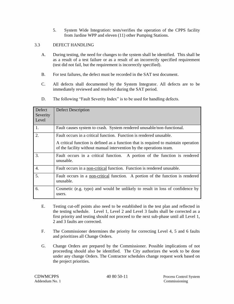
CDWMCPPS 40 80 50-11 Process Control System
Addendum No. 1 Commissioning
5. System Wide Integration: tests/verifies the operation of the CPPS facility
from Jardine WPP and eleven (11) other Pumping Stations.
3.3 DEFECT HANDLING
A. During testing, the need for changes to the system shall be identified. This shall be
as a result of a test failure or as a result of an incorrectly specified requirement
(test did not fail, but the requirement is incorrectly specified).
B. For test failures, the defect must be recorded in the SAT test document.
C. All defects shall documented by the System Integrator. All defects are to be
immediately reviewed and resolved during the SAT period.
D. The following “Fault Severity Index” is to be used for handling defects.
E. Testing cut-off points also need to be established in the test plan and reflected in
the testing schedule. Level 1, Level 2 and Level 3 faults shall be corrected as a
first priority and testing should not proceed to the next sub-phase until all Level 1,
2 and 3 faults are corrected.
F. The Commissioner determines the priority for correcting Level 4, 5 and 6 faults
and prioritizes all Change Orders.
G. Change Orders are prepared by the Commissioner. Possible implications of not
proceeding should also be identified. The City authorizes the work to be done
under any change Orders. The Contractor schedules change request work based on
the project priorities.
Defect
Severity
Level
Defect Description
1. Fault causes system to crash. System rendered unusable/non-functional.
2. Fault occurs in a critical function. Function is rendered unusable.
A critical function is defined as a function that is required to maintain operation
of the facility without manual intervention by the operations team.
3. Fault occurs in a critical function. A portion of the function is rendered
unusable.
4. Fault occurs in a non-critical function. Function is rendered unusable.
5. Fault occurs in a non-critical function. A portion of the function is rendered
unusable.
6. Cosmetic (e.g. typo) and would be unlikely to result in loss of confidence by
users.
CDWMCPPS 40 80 50-12 Process Control System
Addendum No. 1 Commissioning
3.4 SUCCESSFUL COMPLETION
A. The SAT is deemed successful when the following items have been completed:
1. SAT Test plan has been completed and signed-off.
2. All Level 1, 2 and 3 faults identified during the SAT have been corrected
and verified for correct operation.
3. The completed SAT plan has been reviewed and signed off by the
Contractor, System Integrator and The Commissioner.
3.5 FACILITY STARTUP PERIOD
A. Following successful completion of the SAT testing, the startup period may
commence. Contractor, Commissioner and System Integrator, are to be present
during the startup period.
B. Commissioner maintains a log of faults/deficiencies encountered during the startup
period. The Contractor/System Integrator is to immediately correct
faults/deficiencies at the request of the Commissioner. If any Level 1, 2 or 3 fault
occurs during the startup period, the test period shall be restarted from Day 1 after
completion of the software modifications and testing by the System Integrator.
C. Following completion of the startup period, the fault/deficiency log is submitted to
the Commissioner for review. Sign-off by Contractor, System Integrator, and the
Commissioner is required at the completion of the facility startup period.
3.6 TRAINING
A. Provide training in coordinated with and in accordance with the requirements
contained in Section 01 79 00 and detailed in Section 40 98 00, and related
sections.
END OF SECTION

CDWMCPPS 40 90 00-1 Process Control System
Addendum No. 1 General Requirements
SECTION 40 90 00
PROCESS CONTROL SYSTEM GENERAL REQUIREMENTS
PART 1 GENERAL
1.1 SUMMARY
A. Section includes requirements for furnishing and installing process control system
(PCS) including all labor, materials, equipment and incidentals as shown, specified
and required to furnish, install, calibrate and place in operation a complete system
as illustrated on drawings, and as specified in the following related sections:
B. Related work specified in other sections includes, but is not limited to the
following:
1. Section 01 33 00 - Submittals
2. Section 26 05 10 - Basic Electrical Material and Methods
3. Section 40 80 50 - Process Control System Commissioning
4. Section 40 90 50 - Process Control System General Requirements
5. Section 40 91 00 - Process Control System Instruments
6. Section 40 94 13 - Process Control Systems Computer and Network
Hardware
7. Section 40 94 43 - Programmable Logic Controller Systems
8. Section 40 95 13 - Process Control System Panel Enclosure and Equipment
9. Section 40 96 15 - Process Control System Input and Output List
10. Section 40 98 00 - Process Control System Training
11. Section 40 98 50 - Process Control System Factory Testing
C. Provide all labor, materials, equipment, and incidentals as shown, specified, and
required to furnish, install, calibrate, test, start-up, and place in satisfactory
operation a complete process control system. The Contractor shall be responsible
for all elements specified and furnished as part of this section and related sections.
D. Substantial documented experience required for company specializing in
performing the work of this section. Assign complete responsibility for furnishing,
coordination, assembly, factory and field testing, installation supervision, training
and PLC services of all equipment to a qualified (as defined above) Systems
Integrator for manufacture, assembly, and production of systems of the type
specified. Provide a complete, satisfactory, and trouble-free operating installation.
1. System Integrator's Responsibilities
a. Engineering, furnishing, installation supervision, fabrication,
implementation and programming of the Process Control System and
all subsystems, including PLCs, instruments, field panels, networking
and network communication system, interface with the existing

CDWMCPPS 40 90 00-2 Process Control System
Addendum No. 1 General Requirements
Jardine WPP SCADA system and eleven other Pumping stations , and
all related instruments and controls in accordance with the Contract
Documents and all referenced standards and codes.
b. Preparation, assembly and correction of all submittals in accordance
with the Contract Documents.
c. Proper interfacing of the new equipment and panels, including
required interfacing with packaged control systems furnished by other
equipment suppliers, and integration with the existing Jardine WPP
control system and eleven other Pumping stations.
d. Supervision of the installation of all equipment required.
e. Calibration, testing and start up
f. Training of City personnel in operation and maintenance of the
process control system.
g. Handling of all warranty obligations for the system components.
h. Maintenance of two up-to-date reproducible copies of the complete
system and application software at the System Integrator's facility for
the duration of the warranty period. Software copies shall be
maintained and shall be directly loadable on the supplied system.
i. System Integrator shall retain the services of a certified Cisco
technician for programming of all switches, routers, and other Cisco
network devices.
1.2 REFERENCES
A. Section 01 42 00 – References.
B. Codes and Standards referred to in this Section are:
1. IEEE 802.3 10/100/1G Ethernet networks
2. ISA-S5.4 Instrument Loop Diagrams.
3. NFPA 70 National Electrical Code
4. UL Underwriter’s Laboratory
5. NEMA National Electrical Manufacturers Association
6. City of Chicago Electric Code

CDWMCPPS 40 90 00-3 Process Control System
Addendum No. 1 General Requirements
1.3 QUALITY CONTROL
A. General: Provide quality control, as specified in Section 01 45 00 – Quality
Control.
1.4 QUALITY ASSURANCE
A. Pre-Submittal Conference:
1. Arrange and Conduct a pre-submittal conference on the process control
system (PCS) within 30 days of notification of preliminary acceptance of the
proposed supplier by the Commissioner.
2. The pre-submittal conference shall be attended by representatives of the
Contractor, System Integrator, and the Commissioner.
3. Allocate one full working day for the conference and that time shall be
included in the price of this Contract. The pre-submittal conference shall be
held at the job site or as located by the Commissioner.
4. The purpose of the pre-submittal conference is to review informally and
approve the manner in which System Integrator intends to respond to the
Contract requirements before any submittals are prepared.
5. Prepare the items listed below for presentation at the pre-submittal
conference. Submitted the information to the Commissioner three weeks
prior to the date of the conference.
a. A notarized letter signed by an Officer of System Integrator stating
that it has received a copy of all Contract Documents from the
Contractor including Specifications, all Division 1 Specifications, and
a complete set of Contract Drawings.
b. Resume of individual who shall be the Contractor’s coordinator for all
instrumentation and control issues furnished under all sections of the
Contract. Resume of the System Integrator Project Manager. Factory
Training certificates for all staff for programming and configuration.
c. List of equipment and materials required for the control system and
the brand and model which the Contractor proposes to use for each
item.
d. List of proposed exceptions to the plans and specifications along with
a brief explanation and justification of each, including cost impact.
Approval of the exceptions is not automatic and shall be subject to a
formal submittal review process.

CDWMCPPS 40 90 00-4 Process Control System
Addendum No. 1 General Requirements
e. Sample of each type of submittal specified herein. These may be
submittals prepared for other projects.
f. A flow chart showing the steps to be taken in preparing and
coordinating each control system submittal to the Commissioner, and
a list of proposed submittals.
g. Bar chart type schedule for all Process Control related activities from
the pre-submittal conference through start up and training. Particular
emphasis shall be given to dates relative to submittals, design,
fabrication, programming, factory testing, deliveries, installation and
field testing. The schedule shall be subdivided to show activities
relative to each major item or group of items when everything in a
given group is on the same schedule.
h. General outline of the type of tests to be performed to verify that all
sensors/transducers, instruments and digital processing equipment are
functioning properly. Tests shall include field calibration procedures,
field-testing, start-up procedures, and factory testing.
1.5 ABBREVIATIONS
A. EIA – Electronic Industries Association.
B. GUI –Graphical User Interface.
C. HIM – Human Machine Interface
D. IM – Instrumentation Manufacturer.
E. OAD – Operational Availability Demonstration.
F. OIT – Operator Interface Terminal.
G. OWS – Operator Workstation.
H. PCS – Process Control Systems.
I. PID – Proportional, Integral, Differential.
J. PLC – Programmable Logic Controller.
K. RAW – Remote Area Workstation.
L. RIO – Remote Input/Output.
M. SCADA – Supervisory Control and Data Acquisition.
N. UPS – Uninterruptable Power Supply.

CDWMCPPS 40 90 00-5 Process Control System
Addendum No. 1 General Requirements
1.6 SPARE PARTS
A. Not Used
1.7 DEFINITIONS
A. Process Instrumentation and Control Equipment (Equipment): Instrumentation and
control and monitoring components such as field elements, panels, process control
systems and associated electromechanical, electrical, and electronic accessories.
B. Process Instrumentation and Control System (System): Materials, equipment and
work required to implement a complete and operating system of instrumentation
and control equipment.
C. PLC: Programmable Logic Controller system, including power supply, central
processing unit (CPU), communication controller, interconnect cables, and input
and output interface.
1.8 SYSTEM DESCRIPTION
A. Provide all materials and work necessary for implementation of a complete and
fully functional PCS as shown, specified, and described.
1. Provide instrumentation and control components as well as complete system
integration.
2. Provide all mounting hardware and supports. Work shall include panel
mounting and the completion of all wiring terminations within control
panels.
3. Coordinate work with all electrical, mechanical, and structural work
furnished in this Contract.
4. Install, make final connections, adjust, test, start-up systems per contract
documents and manufacturer’s instructions and recommendations.
B. Design Requirements
1. Provide complete instrumentation and control system design for
implementation of work shown and specified for the pumping station
additions and modifications as described in the contract documents.
2. The design documents detail minimum equipment requirements necessary
for the new process control system integration into the existing Jardine WPP
SCADA system and eleven other pumping stations, which include all work
performed in this Contract.

CDWMCPPS 40 90 00-6 Process Control System
Addendum No. 1 General Requirements
C. Network Communication Requirements
1. Provide Ethernet ready PLC systems.
2. Provide fiber optic connections where required.
3. Provide Network Access Panels and Network Core Panels with patch panels,
switches, routers, network switches, power supplies and associated
accessories where required.
D. Source Code Ownership
1. All developed control logic applications (along with source code) shall
become property of the Commissioner. This applies to all control logic
applications associated with package control systems.
2. All developed OIT and HMI applications (along with source code) shall
become property of the Commissioner. This applies to applications
associated with the package control systems.
1.9 SUBMITTALS
A. General: Provide all submittals, including the following, as specified in Division
01, Sections 01 33 00.
B. Action Submittals
1. Product Data: Submit manufacturer’s official and published product data,
specifications, and installation recommendations for each item.
2. Shop Drawings: Submit shop drawings as per Section 01 33 00, and as
required below. Include the following information in each submittal:
a. Instrument index, including tag number, description, location, and
calibrated range for each instrument.
b. Individual instrument specification sheet, including manufacturer's
name and complete catalog number.
c. Panel construction drawings with dimensions, layout and bill of
materials.
d. Panel wiring diagrams
e. Loop diagrams
f. Communication and networks diagrams
g. Campus Network layout.

CDWMCPPS 40 90 00-7 Process Control System
Addendum No. 1 General Requirements
3. Include connections to Ethernet network identify cable, termination type,
termination location, and drop lengths for each segment.
a. Provide Network schematic for each different type of network.
b. Input and Output drawings, containing, but not limited to, the
following information:
(1) Line numbers and instrument tag numbers
(2) Individual component locations
(3) Actual equipment wiring terminal designations, point to point
wiring, and cable shield terminations
(4) Wire type, size and identification number
(5) Signal types (e.g., 120 Volt ac, 4-20 mAdc, pulse frequency,
etc.)
(6) Contact orientations (e.g., normally open, normally closed, etc.)
(7) Equipment grounding requirements
(8) Signal boosters, interposing relays, optical isolators, and shunt
resistors.
c. Completely developed process screens for OITs and HMI.
C. Information Submittals
1. Test Reports: Submit all loop field calibration reports.
2. Factory and Field Testing: Provide the following:
a. Test Results:
(1) Pass/fail status of all digital I/O.
(2) Results of analog I/O testing.
b. Miscellaneous:
(1) Detailed step-by-step in-factory and field test procedure at least
6-weeks in advance of scheduled test date. Include sign-off
sheets and punch list forms and description of configurations to
be tested.

CDWMCPPS 40 90 00-8 Process Control System
Addendum No. 1 General Requirements
(2) Complete inventory of equipment to be tested at factory
including make, model, and serial number. Label each piece of
equipment.
(3) Preventive maintenance schedule.
(4) Repair Report Forms.
(5) Spares and Consumables requirements.
3. Manufacturer’s Instructions: Submit manufacturer published installation
manuals and operations manuals for each instrument, device, or equipment.
D. Submittals for Closeout: Provide submittals as required below.
1. Project Record Documents: In addition to requirements described in Section
01 78 00, provide the following:
a. Program documentation: Provide paper copies of all software
development and configuration including listing of all register tables
and/or tags.
b. Include functional narrative description of the developed control logic
to describe each control system. Control logic is to be annotated as
specified in Section 40 94 43 to include functional alphanumeric
description of logic elements to assist the Commissioner in
understanding the control logic for troubleshooting and future
modification.
c. Program copies: Provide two digital copies of fully configured
systems. Digital copies shall be in CD-ROM format.
d. Operator interface program copies: Provide hard copy printouts and
digital copies of new or modified OIT and HMI screens and database
listings. Digital copies shall be in CD-ROM format.
2. Operation and Maintenance Data: Provide operation and maintenance
manuals as specified in Division 1. Include the following information:
a. Recommended spare parts list.
b. Manufacturer approved repair and service centers list.
c. Replacements part sources.
d. Recommended maintenance procedures and frequencies.
3. Warranty: Provide warranty certificate as described in, Section 01 78 90.
CDWMCPPS 40 90 00-9 Process Control System
Addendum No. 1 General Requirements
1.10 REFERENCES
A. Regulatory Requirements
1. Code Compliance: Comply with National Electrical Code (NFPA 70) and
any and all local codes including City of Chicago Electric Code, applicable
to construction and installation of electrical wiring, devices, material and
equipment.
2. NECA Standards: Comply with applicable portions of National Electrical
Contractor’s Association’s “Standard of Installation”.
3. UL Labels: Provide control panel components, power supplies, controllers,
relays, etc., which have been listed and labeled by Underwriter’s
Laboratories.
B. The purpose of Contract drawings and specifications is to convey information
required for complete and functioning systems. System Integrator is responsible
for all details necessary to properly install, adjust, and place in operation, intended
systems. “Instrument Schedule” and “Input and Output Lists” are provided for
convenience; their accuracy is not guaranteed.
1.11 SCOPE OF WORK
A. Provide application software programming as specified in Section 40 90 50
Process Control System Descriptions.
B. Provide Interconnecting Wiring Diagram Drawings for the Process and
Instrumentation Control System.
C. Immediately correct incomplete or deficient Work discovered during application
software programming, downloading, testing, troubleshooting, and System startup.
D. Detailed Design and Configuration of the Ethernet networks for the devices
specified herein and as shown on the Drawings.
E. For Process Control System control panels, components, and ancillaries specified
under this section.
1. Coordinate to ensure that: The proper size, type and number of Process
Control System related raceways and conductors are provided and installed.
2. Complete panel fabrication drawings.
3. Provide the specified submittals.
4. Provide panels, components and ancillaries.
5. Certify correctness of installation.

CDWMCPPS 40 90 00-10 Process Control System
Addendum No. 1 General Requirements
6. Verify final power and signal connections and labeling (lugging and
connecting).
7. Adjust and calibrate.
8. Starting up
9. Testing
10. Provide the required training per this, related sections including 40 98 00
and Division 1.
11. For systems, components, and ancillaries not provided under this Section but
that are directly connect to components provided under this Section.
a. Obtain manufacturers’ information regarding installation, interface,
function and adjustment.
b. For operation and control, verify that installations, interfacing signal
terminations and adjustments have been completed in accordance
with manufacture’s recommendations.
c. Test to demonstrate proper interface and operation with PCS.
1.12 APPLICATION SOFTWARE PROGRAMMING
A. Provide application software programming as required in this and related Sections.
Download and test application software programming after successful completion
of Process Control System Factory Testing specified in the related Section 40 98
50 and Process Control System Commissioning in Section 40 80 50.
B. Training Services specified in Section 40 98 00 in Section 01 79 00 shall not begin
until System Integrator has successfully completed application software
programming, downloading, and Site Acceptance Testing. See Section 01 12 16
for specified construction sequences and constraints that affect completion of
application software programming, downloading, and testing.
C. The Commissioner reserves the right to negotiate software license agreement
directly with the software supplier
1.13 DELIVERY, STORAGE, AND HANDLING
A. Deliver, store, and handle all products and materials as specified in Section 01 60
00.
B. Packing and Shipping

CDWMCPPS 40 90 00-11 Process Control System
Addendum No. 1 General Requirements
C. Inspect all materials and equipment against approved shop drawings at time of
delivery. Immediately return for replacement or repair any equipment or materials
damaged or not meeting requirements of approved shop drawings.
D. Label all equipment and materials after they have been inspected. Store all
equipment and materials in dry, covered, ventilated location. Protect from harm in
accordance with manufacturer’s recommendations.
1.14 PROJECT/SITE CONDITIONS
A. Environmental Requirements: Protect all equipment and instruments specified
herein from all harmful elements such as moisture, dust, chemicals, rodents etc.
1.15 SEQUENCING AND SCHEDULING
A. Refer to Section 01 12 16 for Contractor’s scheduling requirements for
applications software testing.
B. Prerequisite Activities and Lead Times: Do not start following key Project
activities until prerequisite activities listed below have been completed and
satisfied:
1. Shop Drawing Reviews by Commissioner:
a. Prerequisite: Commissioner’s acceptance of Schedule of Values and
Progress Schedule.
2. Training
a. Prerequisite: Associated training plan submittal approved.
b. Prerequisite: Offsite Training plan submittal approved
PART 2 PRODUCTS
2.1 SERVICE CONDITIONS
A. Standard Service Conditions: The following defines certain types of environments.
Process Control subsections refer to these definitions by name to specify the
service conditions for individual equipment units. Design equipment for
continuous operation in these environments, :
1. Server Room, Air Conditioned:
a. Temperature: 60 degrees F to 80 degrees F.
b. Relative Humidity: 40 percent to 60 percent.
CDWMCPPS 40 90 00-12 Process Control System
Addendum No. 1 General Requirements
c. NEC Classification: Nonhazardous.
2. Inside, Air Conditioned:
a. Temperature:
(1) Normal: 60 degrees F to 80 degrees F.
(2) With Up to 4-Hour HVAC System Interruptions: 40 degrees F
to 105 degrees F.
b. Relative Humidity:
(1) Normal: 10 percent (winter) to 70 percent (summer).
(2) With Up to 4-Hour HVAC System Interruption: 10 percent to
100 percent.
c. NEC Classification: Nonhazardous.
3. Inside:
a. Temperature: 20 degrees F to 104 degrees F.
b. Relative Humidity: 10 percent to 100 percent.
c. NEC Classification: Nonhazardous.
4. Outside:
a. Temperature: Minus 20 degrees F to 104 degrees F.
b. Relative Humidity: 10 percent to 100 percent, rain, snow, freezing
rain.
c. NEC Classification: Nonhazardous.
2.2 SYSTEM ARCHITECTURE
A. Provide Campus layout drawings in a hierarchal order showing network access
panel locations, process control panels, connections types, and drops, for PLCs,
network devices and supervisory equipment. Network shall be redundant, fault
tolerant, self-healing.
2.3 MONITORING AND CONTROL – GENERAL
A. Functional descriptions of the processes and equipment to be monitored and
controlled by (or through) the Process Control System are specified in Sections 40
90 50 and related sections.

CDWMCPPS 40 90 00-13 Process Control System
Addendum No. 1 General Requirements
B. Configure the PLC system to meet the functional requirements specified in Section
40 94 43 and related sections.
C. Coordinate the HMI configuration programming with the configuration of the
SCADA Servers specified in Section 40 94 13.
D. I/O points (Hard and Virtual Points)
E. Examine status of operating mode input from each equipment item/group. PLC
control logic and outputs shall only be activated if the equipment is in the proper
operating mode (auto, remote, as applicable).
F. In general, all control discrete outputs for starting and stopping equipment are to
be configured as maintained “Run” signal commands which shall be released
during a power failure. Exceptions to this approach are noted in the respective
control strategy descriptions.
2.4 TYPICAL MONITORING AND CONTROL STRATEGIES
A. Continuous Process Signal Monitoring
1. Indicate each continuous process signal monitored on Operator Interface
systems in direct engineering units.
2. Allow programming of the following operator adjustable alarm points for
each process signal:
a. High High
b. High
c. Low
d. Low Low
e. High Rate of Change
Each of the above parameters shall be capable of being set, but the actual
number of alarm points configured is to be determined per signal.
3. Generate an alarm when process signal is out-of-range.
B. Typical Setpoint Control Adjustment
1. Each operator adjustable timer and process variable setpoint shall be
provided with minimum and maximum limits.
2. Provide numerical fields for setpoint entry. Do not use sliders. Setpoint
entries shall be in direct engineering units.

CDWMCPPS 40 90 00-14 Process Control System
Addendum No. 1 General Requirements
3. Provide out-of-range warning messages if attempts are made to set setpoints
less than the minimum limit, or greater than the maximum limit.
C. Equipment Runtime Totalizations
1. Configure PLCs to accumulate runtime totals from the running status inputs
for all motor driven equipment (pumps, fans, etc).
2. Display total runtime hours on each respective SCADA display screen
where shown.
D. Analog Data
1. The following data processing capabilities for analog points shall be
provided:
a. Engineering units conversion – Except as otherwise specified all
analog point raw values shall be converted to engineering units via a
linear transformation.
b. Rate-of-Change limit checking – Analog data shall be checked for
rate-of-change limit values. For each analog value, the total net
change in value since the last scan of the point shall be computed and
compared against a pre-defined limit value. An alarm shall be
generated if the limit is exceeded. A dead band value equal to a
percentage of this rate-of-change limit value shall also be used in
determining the return-to-normal condition.
c. Alarm checking- the following alarm conditions shall be checked
when enabled:
(1) Alarm limits (high-high and low-low)
(2) Caution limits (high and low)
(3) Rate of change
(4) The alarm limits are checked first and if not exceeded, caution
limits are checked. Return-to-normal of limit alarms shall be
filtered by a dead band. Each limit and dead band value shall
be adjustable by the operator and defined on a per point basis.
E. Control Strategy
1. Provide a self contained control system as specified in Sections 40 94 43.
2. Develop HMI and OIT screens, as listed below per City’s standards.
a. All pumping stations processes

CDWMCPPS 40 90 00-15 Process Control System
Addendum No. 1 General Requirements
b. HVAC status screens
c. Power system
d. Individual switchgear (showing breaker positions and power
monitoring)
e. Individual switchgear (showing breaker positions and power
monitoring)
2.5 DEVICE CONTROL
A. The control software shall recognize several control modes. The modes of control
reflect either field status of the equipment connected to the PLC/SCADA or
operator commands. Switching between control modes, such as auto/manual or
remote/local shall be bumpless. Equipment status shall be traced by the
PLC/SCADA and shall not change when modes are changed. The control modes
are organized in a hierarchical manner as follows:
1. CP0 (Local): A field operator controls the process equipment (gate) from the
Gate Actuator. In effect this mode is always a Manual Mode.
2. CP1: The equipment is controlled by the panel OIT via local PLC.
3. CP2: The equipment is controlled from the HMI in the Control Room of the
Pumping Station.
4. CP3: The Equipment is controlled from Jardine WPP.
5. Remote: The equipment is controlled by the PLC. The PLC has two
variations:
a. Manual: The equipment is controlled by an operator from the
OIT/HMI through Start/Stop or Open/Close commands or by issuing
set-points to the controllers.
b. Auto: An automatic control strategy executing in PLC controls the
equipment.
2.6 GRAPHIC DISPLAY REQUIREMENTS
The displays will include at a minimum all the equipment shown in the P&IDs and
described in the control narratives. All equipment shall be labeled as shown on the
drawing or as listed in the I/O list. The HMI and OIT graphics shall be based on
City standards as employed in other facilities.

CDWMCPPS 40 90 00-16 Process Control System
Addendum No. 1 General Requirements
PART 3 EXECUTION
3.1 INSTALLATION
A. General
1. Install all instruments and equipment in strict compliance with
manufacturer's instructions.
2. Mount all gages and indicators in upright position.
3. Provide sufficient space around equipment for maintenance and removal of
equipment without removal of adjacent equipment.
4. Cover front panels, gages and indicators during construction for protection
from dust, weld and paint splatter.
5. Unless otherwise impractical, mount all indicating instruments at eye level
(5 feet).
6. Unless otherwise impractical, support instruments independent of process
piping.
B. Hardware Installation
1. Provide aluminum or stainless steel support channels.
2. Provide 1/4-inch thick minimum, clear anodized aluminum equipment
mounting plates.
3. Provide gaskets to prevent galvanic reaction between dissimilar metal
surfaces.
C. Equipment Identification and Instrument Tags
1. Install embossed stainless steel tags for each device, instrument, and panel
meeting requirements as specified in Section 26 05 53.
2. Provide an engraved laminated plastic plate at each wall-mounted
instrument and panel, indicating panel and instrument function and tag.
3. Engraved laminated tag colors: Provide black lettering on white background.
Mount tags at eye level.

CDWMCPPS 40 90 00-17 Process Control System
Addendum No. 1 General Requirements
3.2 QUALITY CONTROL
A. Inspection: Demonstrate that instruments, panels, Network Access points and PLC
equipment,
1. Has not been damaged by transportation or installation,
2. Has been properly installed,
3. Has no mechanical defects,
4. Is in proper alignment, and
5. Has been properly connected.
B. Testing Process:
1. Test digital inputs and outputs by actual starting and stopping of equipment
when possible, or with jumpers at field equipment terminals.
2. Test analog inputs and outputs by a signal generator at 0, 50 and 100 percent
ranges.
3. Conduct all tests in presence of Commissioner.
C. Manufacturers Field Service: Provide manufacturer field service for calibration,
initial setup, programming and commissioning of each instrument.
END OF SECTION

CDWMCPPS 40 90 00-18 Process Control System
Addendum No. 1 General Requirements
(NO TEXT FOR THIS PAGE)

CDWMCPPS 40 90 50-1 Process Control System Addendum No. 1 Description
SECTION 40 90 50
PROCESS CONTROL SYSTEM DESCRIPTION
PART 1 GENERAL
1.1 SUMMARY
A. Section includes requirements for furnishing and installing instrumentation and
control systems including all work and materials necessary to perform control and
monitoring functions as illustrated on drawings, and as specified in the following
sections.
B. Related work specified in other sections includes, but is not limited to the
following:
1. Section 01 33 00 - Submittals
2. Section 26 13 11 – Medium-Voltage Switchgear Operational Sequence
3. Section 40 05 20 - Valves
4. Section 40 80 50 - Process Control System Commissioning
5. Section 40 91 00 - Process Control System Instruments
6. Section 40 94 43 - Programmable Logic Controller Systems
7. Section 40 94 13 - Process Control Systems Computer and Network
Hardware
8. Section 40 95 13 - Process Control System Panel Enclosure and Equipment
9. Section 40 96 15 - Process Control System Input and Output List
10. Section 40 98 00 - Process Control System Training
11. Section 40 98 50 - Process Control System Factory Testing
1.2 SYSTEM DESCRIPTION
A. General Description of Work
1. Provide a complete process control system including networking and
software development for Central Park Pumping Station.
2. The Instrumentation and Control documents are guidelines to assist the
contractor with the detailed design of control system including the Ethernet
networks and communication with Jardine WPP and eleven other Pumping
stations.
3. Installation and commissioning of control system for individual pumps are
phased. Contractor shall install the control system backbone including the
network cabling, servers, switches, routers and network panels prior to
installation of PLC panel for the first scheduled pump.

CDWMCPPS 40 90 50-2 Process Control System Addendum No. 1 Description
4. The Site Acceptance Testing shall be performed for each pump individually
and with other converted pumps as a system. This process shall be
performed for all pumps and associated equipment due to phasing nature of
the work.
5. Relocate the existing monitoring system cabinet to the Server room when its
current location is scheduled for renovation.
6. Replace the SCADA servers furnished under this contract with new ones at
the completion of the construction at the discretion of Commissioner.
Furnish large screen monitors for SCADA system in the Control Room as
directed by Commissioner.
7. Develop IFix HMI screens at CPPS and replicate them at Jardine WPP and
eleven other Pumping Stations following City’s graphics used in similar
stations. Coordinate with the Commissioner to review the City’s existing
HMI screens.
B. The Control Descriptions specified herein provide the functional requirements of
the Control represented in the Contract Documents.
1. Descriptions will be provided as follows:
a. Control system overview and general description.
b. Equipment to be controlled.
c. Major Field mounted instruments (does not include local gauges).
d. Manual control functions.
e. Automatic control functions/interlocks.
f. Major indications provided at local control panels.
g. Remote indication and alarms.
C. The Control Descriptions are not intended to be an inclusive listing of all elements
and appurtenances required to execute loop functions, but are rather intended to
supplement and complement the Drawings and other Specification Sections. The
Control Descriptions shall be the base document for the Contractor creation of the
Control Strategies. Identification of required elements, documentation, and
coordination between loops are to be developed during shop drawings. Finalizing
and tuning of strategies, as required by process characteristics, are to be completed
during startup.

CDWMCPPS 40 90 50-3 Process Control System Addendum No. 1 Description
1.3 SUBMITTALS
A. General: Provide all submittals, including the following, as specified in Division
01, Sections 01 33 00.
B. Action Submittals
1. Product Data: Submit manufacturer’s official and published product data,
specifications, and installation recommendations for each item.
2. Shop Drawings: Submit shop drawings as per Section 01 33 00, and as
required below. Include the following information in each submittal:
a. Complete control descriptions/strategies developed from the Control
Descriptions specified.
b. I/O List complete with Instrument Ranges and Alarm levels,
setpoints.
c. Each permissive detailed.
d. Provide complete control description for all areas of control.
Including sufficient detail for a complete understanding of each
operator controllable set point, failure modes, flow balancing and
pressure controls.
e. All screens for all control strategies shall be completed and included
in the submittal.
C. Contract Closeout Information Submittals: Provide submittals as required below.
1. Project Record Documents: In addition to requirements described in Section
01 78 00, Contract Close Out, provide the following:
a. Program documentation: Provide paper and electronic copies of all
software development and configuration including listing of all
register tables.
2. Operation and Maintenance Data: Provide operation and maintenance
manuals as specified in Division 1. Include the following information:
a. Recommended spare parts list.
b. Manufacturer approved repair and service centers list.
c. Replacements part sources.
d. Recommended maintenance procedures and frequencies.

CDWMCPPS 40 90 50-4 Process Control System Addendum No. 1 Description
3. Warranty: Provide one (1) year warranty. Warranty Period will begin as
defined I specifications Book1 – Terms and Conditions for Construction.
1.4 QUALITY ASSURANCE
A. Provide Quality Assurance as specified in Section 01 40 00.
B. The purpose of contract drawings and specifications is to convey information
required for complete and functioning systems. System Suppliers are responsible
for all details necessary to properly install, adjust, and place in operation, intended
systems. “Instrument Schedule” and “Input and Output Lists” are provided for
convenience; their accuracy is not guaranteed.
C. Meetings
1. Schedule the following meetings:
a. Two (2) Process Control System Coordination Meetings and one (1)
I&C Coordination Meeting shall be held to review Project activities,
the submittal schedule, documentation requirements, and application
software programming requirements for the Process Instrumentation
and Control System. During the first coordination meeting, The
Commissioner will review the functional description for the System
and respond to initial questions raised by the System Integrator as to
design intent. The remaining two (2) meetings shall be conducted to
provide The Commissioner Review of programming effort and further
clarification of design intent for the functional description of the
System.
b. Process Control System Coordination Meetings shall be held
regularly at Pumping Station Site as required for the duration of the
contract. System Integrator’s Project Manager, lead designer
specifically assigned to Project, the Contractor and Commissioner,
shall attend each meeting.
c. Process control system testing coordination meetings shall be held in
advance of the SAT for each pump conversion.
d. Progress Meetings shall be held at the Pumping Station Site as
required during commissioning and testing of major equipment.
1.5 RESPONSIBILITY
A. System Integrator shall provide application software programming as specified
herein.

CDWMCPPS 40 90 50-5 Process Control System Addendum No. 1 Description
1.6 SPARE PARTS
A. Not used
1.7 APPLICATION SOFTWARE PROGRAMMING
A. Provide application software programming as specified in this and related
Sections. Download and test application software programming after successful
completion of:
1. Process Control System Factory Testing, as specified in Section 40 98 50,
2. Process Control System Commissioning as specified in Section 40 80 50.
B. Training services, as specified in Sections 01 79 00 and 40 98 00, Training; and
equipment testing and start-up, as specified in Section 01 12 16, Equipment
Testing and Start-Up shall not begin until System Integrator has successfully
completed application software programming, downloading, and testing.
C. Refer to Section 01 12 16, Construction Limitations and Constraints, for specified
construction limitations and constraints that affect completion of application
software programming, downloading, and testing.
1.8 DELIVERY, STORAGE, AND HANDLING
A. Not Required
1.9 PROJECT/SITE CONDITIONS
A. The project is at the Central Park Pumping Station, Jardine WPP, and 11 related
pumping stations and the equipment is subject to humidity, dust, noise, elevated
and reduced temperatures.
1.10 SEQUENCING AND SCHEDULING
A. Refer to Section 01 14 00.
1.11 ACRONYMS
ANSI: American National Standards Institute
CPPS: Central Park Pumping Station
GUI: Graphical User Interface
HMI: Human Machine Interface
IEC: International Engineering Consortium

CDWMCPPS 40 90 50-6 Process Control System Addendum No. 1 Description
OIT: Operator Interface Terminal
OS: Operating System
PDC: Power Distribution Center
PID: Proportional, Integral, Differential
PLC: Programmable Logic Controller
SCADA: Supervisory Control and Data Acquisition
UL: Underwriters Laboratories
PART 2 PRODUCTS
2.1 GENERAL
A. Local Pressure or Curb Pressure or Station Pressure are interchangeable terms and
refers to the same ‘Curb Pressure’.
B. All pump status, alarms and controls input/output points shall be transmitted to
SCADA, Specification Section 40 94 13. The input/output points are listed on
Contract Drawings.
C. Dewatering alarms YH-920C and YHH-920D (HI and HIHI level alarms as
indicated by the Float switches FS-920C and FS-920D) shall inhibit ALL other
alarms in the SCADA system.
2.2 PUMPING SYSTEM OPERATIONAL SEQUENCES
A. Introduction
1. The intent of this document is to provide a detailed description of the control
strategies for the Central Park Pumping Station. This document is used by
the system integrator to design the process control system to meet the
intended design requirements. The Process Control Narrative also serves as
a guide to Operators to provide a better level of understanding for the way in
which CPPS is intended to function.
2. This Process Control Narrative describes the control logic for the following
process components:
a. Monitoring Instruments
b. Main Pump Control
c. Stand-by Generator
CDWMCPPS 40 90 50-7 Process Control System Addendum No. 1 Description
B. Operating Levels
1. Individual pump operation and station operation are defined by the four
operating levels listed below. Each level is described in detail in this
specification.
a. Pump Designation
b. Selection of Station Mode
c. Selection of Control Scheme
d. Selection of Control Point
2. Pump Designation
a. The pump SCADA Screens must show all pumps at the station
assigned to one of the following two designations at all times:
(1) UNAVAILABLE
(2) AVAILABLE
b. Operator must select Pump Designation for each pump.
3. Station Mode
a. The station must be either in MANUAL or AUTO mode.
b. MANUAL: The MANUAL mode shall operate CPPS with
intervention from the Operators. The control systems shall provide the
decisions and Operators shall take the actions.
c. AUTO: The AUTO mode shall operate CPPS with very few inputs
from the Operating Staff. The initial conditions shall be set by the
operators, but as long as “AUTO” mode is active all the decision
makings and actions shall be performed by the control systems. In
AUTO mode pumps will only run in Proportional Control pump
control scheme. This mode shall be programmed and tested.
d. Operator must select Station Mode.
4. Control Scheme
a. The Operator shall select one of the following pump control schemes:
(1) Flow Control – Pump speed is automatically adjusted to
provide the desired flow depending on the operator-entered
flow setpoint for that pump.

CDWMCPPS 40 90 50-8 Process Control System Addendum No. 1 Description
(2) Pressure Control - Pump speed is automatically adjusted to
provide the desired pressure depending on the pressure setpoint
for the station. That setpoint is operator entered “Local
Pressure” which is also referred as “Curb Pressure” or “Station
Pressure”.
(3) Manual Control - Pump speed is automatically adjusted to the
desired speed depending on the operator-entered speed set point
for that pump.
(4) Proportional Control – This control is for station operation and
require minimum two pumps running in this control scheme.
Individual pump speed is automatically adjusted based on the
flow and relative pump capacity to provide the desired pressure
depending on the pressure set point for the station. That set
point is operator-entered and is either “Station Pressure” or
Remote Sensor Point (RSP) modulated. The details about the
RSP are provided later in this section. Proportional Control is
the only available control scheme when the pumping station is
in AUTO Station Mode.
b. Control schemes may be changed while pumps are running only if the
pumping station is operating in MANUAL Station Mode.
5. Control Point
a. Each pump will be operated at either at CP-1, CP-2, or CP-3.
(1) CP-1: The local control panel located at the pump’s VFD. CP-1
can only be selected from the local control panel. When CP-1
control point is selected, control of the pump from CP-2 or CP-
3 shall be disabled.
(2) CP-2: The HMI in the Control Room. CP-2 can only be
selected from the local control panel at the VFD. When the CP-
2 control point is selected from the CP-1 level, control of the
pump from CP-1 shall be disabled.
(3) CP-3: The existing operator station located in the Pumping
Station Control Center at the Jardine Water Purification Plant
(JWPP) control room. CP-3 can only be selected from the
Control Room HMI. When CP-3 control point is selected at
CP-2 (when the selector switch at CP-1 is set to CP-2), control
of the pump from CP-1 or CP-2 shall be disabled.
b. When the pump control is transferred from one level to another (i.e.
CP-2 to CP-3) the transfer shall be bumpless and without interruption
to each pump’s operation.

CDWMCPPS 40 90 50-9 Process Control System Addendum No. 1 Description
C. Pump start-up pre-check
1. The pump SCADA Screens must show all pumps at the station assigned to
one of the following two designations at all times:
a. UNAVAILABLE
b. AVAILABLE
2. The pump SCADA Screen also has a Pump Status indicator, and all pumps
at the station must have one of the following four statuses at all times
assigned by control system:
a. NOT READY
b. READY
c. IN SERVICE
d. ONLINE
3. The following conditions must be met in order for a pump to be ready for
startup:
a. Pump must be designated as AVAILABLE.
b. Pump must be fully primed as indicated by the pump priming valve
float switch.
c. Pump must not be rotating as indicated by the motor shaft speed
optical sensor.
d. Pump Suction Valve must be fully opened as indicated by the suction
valve limit switch.
e. Pump Check Valve must be fully closed as indicated by the check
valve limit switch.
f. Pump Discharge Valve must be fully closed as indicated by the
discharge valve limit switch.
g. Hydraulic pressure must be available at Pump Check Valve as
indicated by the check valve control panel.
h. Pump Oil Lubrication system must have the required flow, pressure
and temperature as indicated by the lube oil system control panel.
i. Pump seals must have the required flow and pressure as indicated by
the seal water flow switches and pressure switches.

CDWMCPPS 40 90 50-10 Process Control System Addendum No. 1 Description
j. No other pump is starting up.
k. Bus voltage must be within limits at the medium voltage switchgear.
l. VFD must not be failed.
m. VFD circuit breaker in the main switchgear must be closed.
n. If above conditions are met, pump will be in READY status. If any of
the above conditions are not met, pump will be in NOT READY
status.
D. Pump Start up
Following successful pre-check, the Pump will be in READY status.
1. Station Mode, Control Scheme, and Control Point are selected.
2. In MANUAL Station Mode, Operator will issue a “START” command. In
AUTO Station Mode, control system will issue “START” command. Upon
receiving a “START” command, the pump is sequenced as below.
3. VFD starts the motor at the minimum speed and slowly ramps up.
4. After the pump discharge pressure exceeds the curb pressure, the control
logic must initiate opening of the pump check valve.
5. Pump check valve must open fully.
6. When the pump check valve reaches the full open position, control logic
activates a “DISCHARGE VALVE READY” signal. In MANUAL Station
Mode, Operator will issue the “OPEN” command to the discharge valve. In
AUTO Station Mode, the control logic will issue the “OPEN” command to
the discharge valve.
7. The discharge valve opens and water must begin to flow as indicated by the
Venturi flow meter.
8. Based on the pump running, check valve open, discharge valve not closed,
and discharge flow above minimum limit indications the pump is designated
as ONLINE.
E. Station Operation
1. The 60MGD and 80MGD pumps are capable of 55MGD and 90MGD,
respectively.
CDWMCPPS 40 90 50-11 Process Control System Addendum No. 1 Description
2. It is assumed that at least two pumps must run at all times, with each of the
pumps fed from a different ComEd substation. Normally the two running
pumps are Pump No. 1 and 2.
3. A third pump must be in READY state for start-up in case of a power
problem with one of the electric lines or when demand exceeds a
predetermined value.
4. In MANUAL Station Mode, selection of which pump(s) to bring online is
the Operator’s decision. In AUTO station mode, the PLC program will
choose the pump(s) as selected by the Operator through the HMI “DUTY
TABLE” (Shown in a later section of this specification).
5. In MANUAL Station Mode, when the pumping station demand increases
and the ONLINE pumps reach their maximum speed without meeting their
respective setpoints, the control logic issues a warning annunciating the need
for an additional pump.
6. In MANUAL Station Mode, when the pumping station demand decreases
and the ONLINE pumps reach their minimum speed without meeting their
respective setpoints, the control logic issues a warning annunciating the need
to stop an ONLINE pump.
7. Individual pumps at CPPS operate within set motor speed, pressure, and
flow limits, as measured by local devices.
F. Station Operation under Proportion Control Control Scheme
1. Pumps can be operated in Proportional Control control scheme only when all
pumps are set to run in the Proportional Control control scheme.
2. The total required flow from all the ONLINE pumps running in Proportional
Control control scheme, as determined by the SCADA system, must be
shared proportionally according to each pump’s rated capacity, i.e. 90MGD
flow requirement, two pumps would be required to run, assume one 80
MGD pump and one 60MGD pump: the load would be split 51.4MGD and
38.6MGD, respectively.
3. Proportional Control control scheme will use a PID control instruction in the
PLCs. It will have the station curb pressure or a Remote Sensing Point
(described below) for its input process variable, and have the pump speed
setpoint as the output controlled variable. This method should allow the
required proportional flow distribution based on relative pump capacity as
well as automatic, quick, and appropriate response to changes in station
pressure when a pump is started, normally stopped, or emergency stopped.
4. Selecting Proportional Control will be allowed only if individual pumps are
in CP-2 or CP-3. When Proportional Control control scheme is selected for

CDWMCPPS 40 90 50-12 Process Control System Addendum No. 1 Description
an ONLINE pump, it will then adjust to distribute the flow proportionately
with other pumps in Proportional Control control scheme, according to
pump capacity.
5. The Proportional Control PID logic will be kept in manual mode when not in
control, with its output set equal to a normal speed percentage, to prevent
windup and allow a relatively bump-less transfer to Proportional Control.
6. Proportional Control can be selected at CP-2 or CP-3, and will be indicated
at all control points. Switching out of Proportional Control control scheme
would leave a pump in Manual Control control scheme. It would then be up
to an operator to select an appropriate control scheme for the pump.
7. The cascaded PID control method outlined above is essential to maintain the
specified proportional division of flow and operation within set parameters
under all conditions.
G. Remote Sensing Point (RSP) Pressure Setpoint:
1. In Proportional Control control scheme the pressure setpoint is operator
entered and is compared to either the Station Pressure or Remote Sensor
Point (RSP) control variable.
2. The station's output flow / delivery pressure is modulated in order to meet
minimum pressure setpoints as measured by existing continuously
monitored RSPs throughout the distribution system. The pressure setpoints
are modified by user interface.
3. Each RSP is given a unique designation.
4. Each RSP is assigned a status by the operator.
a. LIVE - the SCADA System is using that point to determine pump
speed.
b. INACTIVE - the SCADA System is not using the RSP as a parameter
to determine pump speed.
5. Input from up to 20 RSP’s can be monitored by the SCADA System at one
time. RSP’s values are obtained from Jardine WPP through communication
system.
6. While in Proportional Control, if an operator has selected any RSP as "Live,"
it will automatically step the station pressure set-point up or down, in small
steps and at an appropriate rate, if needed to keep the remote site pressure
within its normal range. Step size and rate, remote site pressure ranges, and
the allowed station pressure set-point range will be operator adjustable. The

CDWMCPPS 40 90 50-13 Process Control System Addendum No. 1 Description
number of RSP's chosen as live will be indicated as "No. of RSP's Enabled”
at all control points.
7. An operator at CP-2 or CP-3 is able to manually adjust a range of set points
for each RSP. That range is to be considered the "deadband” for that RSP,
meaning no action will be called for while the pressure remains within that
range.
8. The master pressure set point range for the station is read from the RSP
(RSP-M) located directly outside the CPPS.
9. If the pressure at any of the designated RSP’s moves outside of its deadband,
and remains outside of the deadband for more than 120 seconds, the
SCADA system commands modulation of the speed of the pump motor(s),
by incrementally changing the pressure setpoint of the station, until the
pressure at that RSP is back within the deadband.
a. Should the changing of the motor speed push any of the other RSP's
outside of their respective deadbands (except RSP-M) for more than
10 seconds, the SCADA system commands the speed modulation of
the motor.
b. At that time the SCADA system requests an operator input to which
RSP signal to discard
c. If operator input is not received within 1 minute, the SCADA System
discards the other RPS’s that have gone outside of their respective
deadbands, change their status to inactive, and send an alarm to CP-1,
CP-2 and CP-3
d. At that point modulation continues until the deadband of the original
RSP is reached.
e. If the modulation of the VFD speed in response to an RSP falling out
of its deadband causes the Station Pressure to reach the high or low
limit of its allowed range, modulation of the speed of the VFD stops
immediately, the SCADA System discards the RSP’s that have fallen
out of their respective deadbands, changes their status to inactive, and
sends an alarm to CP-1, CP-2 and CP-3.
10. If pressure at any of the RSP's drops more than 20% in under 1 minute, the
SCADA System disregards that RSP, change its status to inactive, and send
an alarm to CP-1, CP-2 and CP-3.
H. Pump Shut Down
1. When an operating pump is set to stop (either by an operator or if in AUTO
mode by the PLC logic) the following steps must occur consecutively.

CDWMCPPS 40 90 50-14 Process Control System Addendum No. 1 Description
2. Check Valve Closes.
3. VFD reduces the pump speed to minimum.
4. VFD Output contactor opens and pump motor stops.
5. The discharge valve closes.
I. Station Operation Under Fault Conditions:
1. Fault Conditions are defined as:
a. ComEd power is not available.
b. Less than three pumps are available.
c. All Ancillary systems are not available.
d. The SCADA Network functions have communication errors.
e. At least CP-1 or CP-2 control points are not available.
2. The fault condition could be Pumps or their ancillary systems or partial
failure in the SCADA system. The following describes various possible
faults and the methods to deal with them to eliminate or minimize their
impact on the Pumping Station Operations.
a. The Station has Five (5) pumps. The number of pumps in operations
simultaneously is two (2). Upon rising system demand a third pump
may be required to meet the demand.
b. The status of the Motors and Pumps are monitored in real-time by
various field instruments as part of the Motor Management System
(refer to electrical specifications, P&IDs and Instrument index
drawings).
c. The Motor Management System functions independently of SCADA
system. However SCADA system will display all the data received
from the Motor Management system including Alarms and status
points. The Motor Management system is configured to stop a pump
if serious malfunction occur. Refer to Electrical Specification for
more details.
d. Additionally the SCADA system generates alarms based on the
operating parameter of measuring devices. Any major deviations
(selectable by the operating staff) shall cause the SCADA system to
issue alarms detailing the reason.

CDWMCPPS 40 90 50-15 Process Control System Addendum No. 1 Description
e. If a major alarm is issued by the SCADA system and no action is
taken by the operating staff within a pre-set time, the SCADA system
shall take appropriate steps to prevent any damage to equipment or
personnel.
f. The redundancy of the equipment in the pumping station will prevent
any major operation disruption to occur. The number of pumps is
sufficient to withstand losing one or even two pumps at one time. The
management of the failures is mostly done through SCADA system
which issues “Alert”, “Caution” or “Alarm” assisting operating staff
with decision making.
3. Pumping System
a. When a Motor/Pump fails during operation the control system will
issue a major “Alarm”. The major Alarm initiates the shutdown
sequence of the failed pump and its associated equipment, such as
valves. There is the possibility that a device such as Discharge Valve
will not properly operate during a fault. The SCADA shall bypass the
failed step after a preset time and proceed to next shutdown step.
b. When a non- major failure occurs the SCADA system will alert the
Operating staff for decision making.
c. The following are the alarms generated by the SCADA system based
on deviations of operating parameters. If a pump is in “Auto” mode
then the SCADA system will initiate the shutdown of the pump and
issues a major “Alarm”.
d. If the pump is in “Manual” mode SCADA will issue the “Alarm” and
operation staff are responsible for initiation of proper response.
(1) Pump Running but No Flow or Pressure detected
(2) Pump Discharge Pressure Low/High
(3) Pump Failed to Start/Stop
(4) Discharge Valve Failed to Open/Close
(5) Check Valve Failed to Open/Close
(6) VFD failed to reach speed setpoint
(7) Pump Un-commanded Start/Stop
(8) Discharge Valve Un-Commanded Open/Close
CDWMCPPS 40 90 50-16 Process Control System Addendum No. 1 Description
(9) Check Valve Un-Commanded Open/Close
4. Control System and Local Area Network
a. Control system and its backbone network system have been designed
based on multi-level redundancy and backups. In addition the
modularity of the control system provides an important level of safety
against major failures. All devices and cabling, from PLCs, power
sources to Fiber Optic network have hot backups which make the
system “Fault Tolerant”. When a device fails or a cable is
disconnected the backup systems will seamlessly replace them. The
network topology is a ring system. This allows communication
flexibility between devices. If a communication pathway is blocked at
any point on the network the system automatically reverses the
communication path. However no system is totally immune to
failures.
b. Below describe the options available to the operation staff if part of
control system fails.
(1) Pump Control Operation and Monitoring relies on
communication between CP-1, CP-2 and CP-3. The Pumping
Operation shall be monitored from all levels at the same time.
The Control location of the pumps depends on the operation
staff decision.
(2) If Communication between CP-3 and CP-2 fails while CP-3 is
selected as main control point then SCADA system shall:
(a) Transfer the control to CP-2 and issue a Communication
Failed alarm. All the parameter entered from CP-3 shall
be retained.
(b) If the alarm is not acknowledged at CP-2 after a pre-set
time. The pumps control shall be set to “Auto”.
(c) The station operational data shall be stored in the local
storage rather than transmitted to CP-3.
(d) Upon restoration of communication system between CP-
2 and CP-3 the control point shall be returned to CP-3.
The “Auto” mode shall not change unless commanded
by the operating staff at CP-3.
(3) Communication failure between CP-1 and CP-2 requires
immediate action by the operating staff. The operating staff at
CP-2 and CP-3 will not be able to monitor the Pumps

CDWMCPPS 40 90 50-17 Process Control System Addendum No. 1 Description
operation. The control system shall take the following
precautionary steps until the communication is restored:
(a) The controlling level will be transferred to CP-1.
(b) The Pump control mode shall be changed to “Auto” if
communication failure continues for a pre-set time.
(c) Alarms shall be issued at CP-2 and CP-3
(d) Upon restoration of communication system the pump
control shall remain with CP-1 in Auto mode.
(e) The operation staff shall make the decision to change
control mode and parameter.
5. Power failure (Standby Generators)
a. There are four electrical Generator sets which will provide enough
power to CPPS to prevent the shutdown of the station
b. Three Generator sets suffice to run the station the fourth is the
backup.
c. If less than three Generator sets are available, the AUTO Station
Mode shall not be available and transition from AUTO to MANUAL
Station Mode shall be seamless.
d. Generator Paralleling Controller (GPC) shall not allow Pump to start,
if it would overload the Standby Generators as described in 40 90 50.
e. When ComEd power fails the generator sets will start within thirty
seconds.
f. The process control system power is provided by a central UPS with 2
hour backup capacity.
g. Control System Actions during a power failure
(1) The intent of the Control System is to minimize the down time
of the station and ensure pumping operation starts as soon as
possible after a power failure.
(2) Notify lube oil system that power failure has occurred and
allow continued operation of lube oil system on UPS for
designated period, followed by shutdown of lube oil pumps.

CDWMCPPS 40 90 50-18 Process Control System Addendum No. 1 Description
(3) The pumps that were running during power failure shall go
through Stop sequence. It takes approximately 10 minutes for a
pump to go through the stop sequence and be ready for a
restart.
(4) The Check valve operating on Hydraulic Accumulator shall
close when power fails
(5) When the control system receives the closed signal from the
last Check valve it shall begin the process to start the third
pump in automatic.
(6) Operating Staff shall make decision to allow the third pump to
continue running during power failure until ComEd services are
back on line or to start the pumps that were running prior to the
power failure.
(7) The transition from Generators to normal power is seamless.
No action is required from the control system.
6. Servers and Network Devices
a. All devices and cables are redundant. The failure of any individual
device may not impact the operation of the Network.
b. HMI and RSlogix PLC programming tool reside in the SCADA
Servers. A redundancy software creates a Virtual Server allowing the
mirroring of operation of the two servers. If a servers fails the other
will seamlessly take over. An alarm will be issued. The Virtual Server
software shall automatically configure the replacement software
c. The network diagnostic software shall monitor all network devices.
Display the status of the network on the HMI screen. Any failure will
be “Alarmed”.
J. Emergency Stop
1. Fault conditions of either an electrical or mechanical nature must initiate
“Emergency-Stop” operation of an associated pump and must initiate an
alarm.
2. The emergency stop sequence for each pump must be initiated by a fault
condition as described and must be as follows:
a. The pump adjustable speed contactor must trip and the pump must
stop.
CDWMCPPS 40 90 50-19 Process Control System Addendum No. 1 Description
b. Simultaneous with the above, the pump check valve must close at an
adjustable preset speed.
3. The electrical fault sensing devices, malfunction systems, and emergency
push button action that must trip the pump adjustable speed contactor and
initiate the “Emergency Stop” sequence must be as follows:
a. Station flooding trip, as indicated by the Emergency Dewatering
System.
b. The VFD multi-function motor management relay trip command at
the VFD.
c. Check Valve fails to open on pump start or closes when pump is
running.
d. Emergency stop push button operation at CP-1.
e. Emergency stop command sent from CP-2 or CP-3, no matter which
control point is currently selected.
f. Emergency stop push button operation at the motor.
g. Breaker trip operation at the switchgear.
h. Discharge valve remains closed for a set time at start up.
4. The following failure sensing systems and malfunctioning devices for each
pumping unit must be “Alarm Only”, in nature and must not trip the pump
circuit breaker:
a. Motor management relay alarm command.
b. Pump check valve fails to open on pump start or closes when pump is
running.
K. AUTO Station Mode
1. The AUTO Station Mode shall operate CPPS with very few inputs from the
Operating Staff. The initial conditions shall be set by the operators
(described below) but as long as AUTO Station Mode is active all the
decision makings shall be performed by the control systems.
2. The AUTO Station Mode shall be activated/deactivated from CP-2 or CP-3.
3. In AUTO Station Mode start or stop commands from the operators shall start
the appropriate procedures automatically. Steps are monitored and advanced
by the SCADA System based on pre-set parameters.

CDWMCPPS 40 90 50-20 Process Control System Addendum No. 1 Description
4. All control Modes detailed above shall be available in AUTO Station Mode.
The fundamentals of operating CPPS, specifically the concept of running 2
pumps at all times shall be observed.
5. The Operators shall select the operating mode and set points described above
before activating the AUTO Station Mode. The transition to/from AUTO to
MANUAL Station Mode shall be seamless. The following Duty table shall
be activated to enable the Operators to select pumps hierarchy in operating
the station.
DUTY TABLE
Pump
Rank 1 2 3 4 5
Duty 1
Duty 2
Lag 1
Lag 2
Lag 3
6. The AUTO Station Mode program shall start pumps based on selected duty
and shall operate them based on the setpoints and operation mode set by the
operating staff. If a pump should fail the program will substitute the failed
pump with the next available pump.
7. All “Alarms”, “Cautions” and “Warnings” shall be issued by the control
system regardless of the mode of operation.
8. If a pump is not “Ranked” in the duty table the program shall assume that the
pump is not available.
9. If 2 or more pumps are ranked the same the program shall reject the
selections and shall prompt the operating staff to enter different values for
each pump.
PART 3 EXECUTION
Not Used
END OF SECTION

CDWMCPPS 40 91 00-1 Process Control System
Addendum No. 1 Instruments
SECTION 40 91 00
PROCESS CONTROL SYSTEM INSTRUMENTS
PART 1 GENERAL
1.1 SUMMARY
A. Section Includes: Requirements for providing process control system instruments
as detailed in the Instruments’ Specification herein.
B. Related work specified in other sections includes, but is not limited to, the
following:
1. Section 01 32 50 - Project Management System (Constructware)
2. Section 01 33 00 - Submittals
3. Section 01 79 00 - Training
4. Division 26 - Electrical
5. Section 40 90 00- Process Control System General Requirements
6. Section 40 95 13 - Process Control System Panel Enclosure and Equipment
7. Section 40 98 00 - Process Control System Training
1.2 REFERENCES
A. International Society of Automation (ISA).
B. Underwriters Laboratories (UL): Applicable listings.
C. All electrical work shall comply with the requirements of the National Electric
Code (NEC) – Latest Revision.
1.3 SUBMITTALS
A. General: Provide all submittals, including the following, as specified in Division
01, Sections 01 33 00 and 01 32 50.
1. Provide Shop Drawings as required below.
2. Complete and detailed system schematic drawings showing all components
with electrical point to point connections of each system (wiring and piping
diagrams). Include a description of the operation of the system and
equipment.
3. Instrumentation equipment specifications: Include manufacturer’s catalog
information showing product data, outlines, dimensional drawings and

CDWMCPPS 40 91 00-2 Process Control System
Addendum No. 1 Instruments
instructions for installation, storage, handling, and protection. Duplicate
equipment may be covered by one set of literature.
4. Instrument Data Sheets showing actual manufacturer and devices selected,
with all fields completed.
5. The submittal shall be organized in a logical manner and have a schematic
diagram and a loop diagram for each system.
1.4 SUBMITTALS FOR CLOSEOUT
A. Instruction Manuals:
1. Refer to Section 01 78 23.
2. Operation and maintenance information – complete descriptive
literature/shop drawings for each piece of equipment, including a list and
description of all parts of each piece of equipment and instructions for
calibration, testing and maintenance requirements.
3. Project Record Documents: Revisions from the “As-awarded” design and
previous submittals. This includes as built records such as instrument
ranges and actual component/instrumentation locations, including sources of
control power.
4. Revised or updated P&IDs (IC series drawings), and process flow diagrams
showing location of instrumentation and equipment including calibration
data.
5. Submittals of Data Sheets shall be electronic and editable with file naming
based on the device tag.
PART 2 PRODUCTS
2.1 SIGNAL LINE TRANSIENT PROTECTION
A. All signal lines for solid state electronic equipment shall be equipped with line
voltage surge suppressors to protect the equipment from damage due to electrical
transients induced in the interconnecting lines from lightning discharges or nearby
equipment.
B. This shall include, but is not be limited to digital inputs, analog inputs, analog
outputs, flow transmitters and level transmitters. .
C. The signal line transient protection shall include gas discharge tubes, varistors and
suppressor diodes.

CDWMCPPS 40 91 00-3 Process Control System
Addendum No. 1 Instruments
D. Terminal block shall be DIN rail type, mounted in the vertical position.
E. Provide lightning protection termination for all digital and analog signals, plus a
minimum of 10 percent spares per panels.
F. Acceptable Manufacturers are
1. Phoenix Contacts
2. Allen-Bradley
3. Square D
G. Field instruments, for 24V DC analog signals:
1. Conduit Mounted: Protection circuit mounted inside ¾ inch stainless steel
conduit.
2. Provide surge protection for analog and digital I/O designed to withstand a
10kA test current of a (8/20) microseconds waveform according to IEC 1024
Application Guide A and ANSI/IEEE C62.41 Category C Area.
3. Surge protection shall consist of a multistage hybrid circuit utilizing only
diodes and gas discharge tubes but no Metal Oxide Varistors (MOVs).
4. Resistance: Less than 10 ohms of series resistance.
5. Surge protection shall have a response time less than 1 microsecond.
6. Maximum Continuous Operating Voltage: Not to exceed 28V DC.
7. Cutoff Frequency: Less than 400 kHz (for a 600 ohm system) to allow
HART protocol and other superimposed smart digital signals to function.
8. Operating Temperature Range: Minus 40 to 65 degrees C, minimum.
9. Acceptable Manufacturer
a. Phoenix Contact
b. Allen-Bradley
c. Rosemount
2.2 DC LOOP POWER SUPPLIES
A. Each power supply shall be enclosed in a NEMA type 1 enclosure, vertical surface
mounting type, with surface barrier screw terminals for load connection. Each
power supply shall be equipped with a power on/off circuit breaker.

CDWMCPPS 40 91 00-4 Process Control System
Addendum No. 1 Instruments
B. Power supplies shall meet the following specifications:
1. Input Power: 115V AC plus or minus 10 percent, 60 Hz.
2. Output Voltage: 24V DC.
3. Output Voltage Adjustment: 5 percent.
4. Line Regulation: 0.05 percent for 10 percent line change.
5. Load Regulation: 0.15 percent no load to full load.
6. Ripple: less than 3 millivolt RMS.
7. Operating Temperature: 32 to 140 degrees F.
C. Size power supplies to accommodate present load plus 25 percent spare capacity.
D. Provide a relay contact to indicate the on/off status of the power supply.
E. Provide power supply output overvoltage and overcurrent protective devices to
protect the instruments from damage due to power supply failure and to protect the
power supply from damage due to external failures.
F. Mount power supplies such that dissipated heat does not adversely affect other
components.
2.3 TERMINAL BLOCKS
A. Manufacturers:
1. Phoenix Contact
2. Weidmuler
3. Rockwell
B. Terminal Blocks: ANSI/NEMA ICS 4.
C. Power Terminals: Unit construction type with closed back and tubular pressure
screw connectors, rated 600 volts.
D. Signal and Control Terminals: Modular construction type, suitable for channel
mounting, with tubular pressure screw connectors, rated 600 volts.
E. Provide intrinsically safe barriers for signal and control conductors going to
explosion proof areas.

CDWMCPPS 40 91 00-5 Process Control System
Addendum No. 1 Instruments
F. Provide ground bus terminal block, with each connector bonded to enclosure.
2.4 PRESSURE AND DIFFERENTIAL PRESSURE TRANSMITTERS
A. Differential capacitance cell type. Two-wire, 4-20 mAdc output signal. Loop
powered from 24 vDC nominal. Output load impedance of at least 550 ohms.
B. Microprocessor based "smart" electronics. HART protocol compatible.
C. Accuracy: +\- 0.10 percent of calibrated span.
D. Span and zero continuously adjustable, either locally or via hand-held digital
interface.
E. FM approved for installation in Class l, Division l hazardous areas.
F. NEMA 4 housing. Suitable for operation over ambient temperature range of 20 to
120 degrees F.
G. Ceramic or stainless steel wetted parts. Stainless steel bleed and drain fittings. All
metal external parts.
H. Integral 4-digit LCD output indicator graduated 0-100%. Provide integral
mounting bracket suitable for wall or pipestand mounting.
I. 1/2-inch NPT process connections.
J. Manufacturers: Provide products of one of the following:
1. Endress and Hauser Cerabar/Deltabar S
2. Rosemount 3051
2.5 PRESSURE SWITCH
A. Type: Switch assembly with diaphragm/piston pressure sensor.
B. Function: Sense gauge or absolute pressure and open or close a contact when the
pressure reaches the specified trip point.
C. Performance Requirements
1. Operating Range: As specified in the Instrument schedule or as required by
process.
2. Setpoint: As specified in the Instrument schedule.
3. Setpoint Repeatability: ± 1 percent of range.
CDWMCPPS 40 91 00-6 Process Control System
Addendum No. 1 Instruments
4. Output: Snap action switch, DPDT rated not less than ten amp resistive at
120 VAC and 1/2 amp resistive at 125 VDC.
5. Switch and Reset Action: Adjustable Deadband.
6. Adjustable Deadband Range and Setting: maximum full scale, minimum
10% of scale.
7. Ambient Temperature Limits: -4°F to 140°F.
D. Construction Features
1. Pressure Transducer Housing and Diaphragm Materials:
a. Body and Process Connection Bolting: Type 316 stainless steel.
b. Housing and Cover: Die cast low copper aluminum alloy finished
with epoxy paint system; provide covers threaded and seated on
Buna-N O-rings; NEMA 4X rating.
c. Process Wetted Parts: 316 stainless steel.
d. Water Service with Copper Pipe: Brass housing with Buna-N
diaphragm.
e. Other Services: 316 stainless steel.
2. Set and Reset Point Adjustments: Adjustable external adjusting nuts and
pressure setting scales in psi.
3. Process Connection: 1/2-inch NPT.
4. Housing: Copper-free die cast aluminum, NEMA 4X.
5. External Mounting Lugs.
6. Electrical Connection: 3/4-inch NPT.
7. Diaphragm seal.
E. Products and Manufacturers: Provide one of the following:
1. Automatic Switch Company, Tri-point SA Series.
2. United Electric Controls Series 400 (non hazardous areas, series 120 for
hazardous).

CDWMCPPS 40 91 00-7 Process Control System
Addendum No. 1 Instruments
2.6 GAUGES – PRESSURE AND VACUMM
A. General: Provide gauges to include pressure, vacuum and compound gauges of the
dial-indicating bourdon tube type. Provide gauges to the requirements of ASME
B40.100 except as modified herein. Locate gauges as shown or specified. Wall
mount or independently support gauges.
B. Pressure Gauges: Provide Grade 2A pressure gauge with a range of 0 to 100 psig,
with an accuracy of 0.5 percent of the maximum scale reading.
C. Compound Vacuum and Pressure Gauges: Provide Grade 2A compound vacuum
and pressure gauges a vacuum renage of 0 to 30 inches of mercury and pressure
range of 0 to 60 psig with accuracy of 0.5 percent of maximum scale reading.
2.7 DIAPHRAGM SEAL
A. General: Furnish diaphragm seals for pressure gauges and switches at locations
shown and as specified.
B. Required Features
1. Provide fill/bleed screw to permit filling of instrument and diaphragm seal.
2. Instrument Connection: 1/2-inch NPT.
3. Process Connection: 1/2-inch NPT.
4. Working Pressure Rating: Equal to or greater than the attached gauge or
switch operating pressure specified.
5. Bolting Materials: Type 304 for non-wetted exposed parts (typ.) stainless
steel.
6. Provide a clean-out ring which holds the diaphragm captive in the upper
housing to allow the upper housing assembly to be removed for recalibration
or cleaning of the process side housing without the loss of filling liquid or
change in calibration. Flushing connection ¼” NPT.
C. Construction Features
1. Top Housing: Type 316 stainless steel.
2. Diaphragms, O-rings and Gaskets:
3. Process Side Housing Material: 316 SS for metallic piping; CPVC to match
non-metallic piping.

CDWMCPPS 40 91 00-8 Process Control System
Addendum No. 1 Instruments
4. Sensing Liquid: Use silicone except for process fluids containing chlorine.
When the process fluid contains chlorine, provide Halocarbon 63 or
Flurolube 63 for the filling liquid.
5. Working Pressure Rating: Equal to or greater than the attached instrument,
and the operating pressure specified in the Exposed Piping Installation,
section 15109, whichever is greater.
D. Assembly and Calibration
1. Provide complete diaphragm seal assembly, including gauge, switch or
transmitter, shall be factory assembled, filled and calibrated to the ranges
and switch setpoints specified prior to shipment.
2. Coordinate location and orientation of the gauges, switches and seal
assemblies with the actual piping and equipment installations so that gauges
and indicators can be easily read and accessed for maintenance by OWNER
personnel.
3. Where field mounting and orientation conflicts arise due to incomplete
coordination with field changes in the process piping and equipment
installation, relocate, re-orient, re-assemble, and re-calibrate as directed by
the Commissioner at no cost to the OWNER.
E. Product and Manufacturer
1. Type 100 HCF, as manufactured by Bristol Babcock/Helicoid.
2. Type 101 as manufactured by Ashcroft.
2.8 FLOW SWITCH - THERMAL DISPERSION
A. Technical Requirements:
1. Type: Thermal Dispersion
2. Process Connection: 3/4 inch male NPT standard.
3. Insertion Length: 1.2 inches. See installation detail.
4. Sensor Wetted Material: 316 stainless steel with all-welded construction.
5. Operating Temperature: Sensing Element: -40 to 350 Deg F.
6. Control Circuit: Ambient: -40 to 140 Deg F.
7. Operating Pressure: 3500 psig at 70 Deg F.
8. Set point Range: Water-based liquids: 0.01 to 3.0 sfps, 3 watt heater power.

CDWMCPPS 40 91 00-9 Process Control System
Addendum No. 1 Instruments
9. Electrical Enclosure: NEMA 4X, 300 Series Stainless Steel, Class 1,
Division 1.
10. Factory Calibrated Switch Point Accuracy: ±2% of set point velocity over
operating temperature range of ±50 Deg F. See instrument list for set point.
Switch shall be set at factory for decreasing flow. Set point shall also be
field adjustable.
11. Monitoring Accuracy: Liquids: ±5% reading based on a measured output
voltage over the entire flow range, an operating temperature range of ±50
Deg F, and an operating pressure range of ±100 psig.
12. Repeatability: ±0.5% reading.
13. Response Time: 5 to 10 seconds.
14. Input Power: 120 VAC, 60 Hz.
15. Power Consumption: 13VA maximum (AC units), 7 watts maximum (DC
units).
16. Relay Rating: Single DPDT field configurable 6 amp resistive at 115VAC or
24 VDC.
17. Tagging: See instrument index. SS engraved tag required.
2.9 FLOW SWITCH – LOW FLOW
A. Technical Requirements:
1. Type: Insertion
2. Process Connection: 3/4 inch male NPT standard.
3. Insertion Length: 1.2 inches. See installation detail.
4. Sensor Wetted Material: 316 stainless steel with all-welded construction.
5. Operating Temperature: Sensing Element: -40 to 350 Deg F.
6. Control Circuit: Ambient: -40 to 140 Deg F.
7. Operating Pressure: 160 psig at 70 Deg F.
8. Set point Range: Water-based liquids: 0.01 to 3.0 gpm.
9. Electrical Enclosure: NEMA 4X, 300 Series Stainless Steel, Class 1,
Division 1.

CDWMCPPS 40 91 00-10 Process Control System
Addendum No. 1 Instruments
10. Factory Calibrated Switch Point Accuracy: ±2% of set point velocity over
operating temperature range of ±50 Deg F.
11. Monitoring Accuracy: Liquids: ±5% reading based on a measured output
voltage over the entire flow range, an operating temperature range of ±50
Deg F, and an operating pressure range of ±100 psig.
12. Repeatability: ±0.5% reading.
13. Response Time: 5 to 10 seconds.
14. Input Power: 120 VAC, 60 Hz.
15. Power Consumption: 13VA maximum (AC units), 7 watts maximum (DC
units).
16. Relay Rating: Single DPDT field configurable 6 amp resistive at 115VAC or
24 VDC.
17. Tagging: See instrument index and drawings. SS engraved tag required.
2.10 CONDITION MONITORING SYSTEM
A. Furnish a condition monitoring system for each Pump in its Control Panel.
1. Provide Shaft Speed and Vibration monitoring modules as shown on the
Process and Instrumentation Diagram (P&ID).
2. Condition monitoring system shall be Allen Bradley Dynamix 1444 Series
for Vibration and Motor shaft speed. Provide Allen Bradley 1443 Sensors
for vibration sensors and Allen Bradley 1442 sensors for motor shaft speed
sensor.
2.11 LEVEL SWITCH – FLOAT TYPE
A. Type: Direct acting, pear shaped, eccentric weighted, displacement type liquid
level sensor.
B. Construction Features
1. Float Body: Hollow hermetically sealed, rigidly molded of polypropylene
containing mechanical switch and eccentric metal weight.
2. Mechanical Switch: SPDT switch rated 16 amps resistive at 120 VAC and
five amps resistive at 30 VDC.
3. Weight: Weight to cause sensor to hang straight down from cable when not
immersed and only allow float to pivot when immersed in liquid.
CDWMCPPS 40 91 00-11 Process Control System
Addendum No. 1 Instruments
4. Electrical cable:
a. Heavy duty, three conductor, flexible and submersible cable, sheathed
in PVC and connected to float and switch with watertight seal.
b. Length furnished to be sufficient to extend to junction box.
5. Float must be rated to meet the electrical hazard classification.
C. Manufacturers – Provide one of the following:
1. Flygt.
2. Rotofloat
PART 3 EXECUTION
3.1 INTERFACE WITH OTHER PRODUCTS
A. Coordinate installation of, transmitters, and pressure switches with piping and
equipment installers.
3.2 INSTALLATION
A. Install all devices as specified and shown on the Contract drawings and in
accordance with manufacturer’s requirements.
3.3 TRAINING
A. Perform training in accordance with the requirements contained in Section 01 82
00 of these specifications and as specified in the Equipment Datasheets.
3.4 MANUFACTURER’S FIELD SERVICES
A. On-site start up assistance and/or training for operating and maintenance
personnel, calibration, and system testing.
1. Test Schedule
2. Testing Tools
3. Test results
END OF SECTION

CDWMCPPS 40 91 00-12 Process Control System
Addendum No. 1 Instruments
(NO TEXT FOR THIS PAGE)

CDWMCPPS 40 93 50-1 Fiber Optic Cable and Addendum No. 1 Accessories
SECTION 40 93 50
FIBER OPTIC CABLE AND ACCESSORIES
PART 1 GENERAL
1.1 SUMMARY
A. Section Includes: Requirements for providing and placing into successful
operation the fiber optic data highway and appurtenances for the FACILITY
PROCESS Control System network specified. The system includes, but is not
limited to the following:
1. Fiber Optic Patch Cables,
2. Terminal Connectors,
3. Fiber Optic to Copper Converters,
4. Fiber Optic Trunk Cables.
B. Related work specified in other sections includes, but is not limited to the
following:
1. Section 01 33 00 - Submittals
2. Section 01 45 00 - Quality Control.
3. Section 01 42 00 - References.
4. Section 40 80 50 - Process Control System Commissioning
5. Section 40 94 13 - Process Control Systems Computer and Network
Hardware
6. Section 40 94 43 - Programmable Logic Controller Systems
7. Section 40 95 13 - Process Control System Panel Enclosures and
Equipment.
1.2 REFERENCES
A. Standard for Installing Commercial Building Telecommunications Cabling
(ANSI/NECA/BICSI 568).
B. International Society of Automation (ISA).
C. Electronics Industry Association (EIA).
D. Color Coding of Fiber Optic Cables (TIA-598).

CDWMCPPS 40 93 50-2 Fiber Optic Cable and Addendum No. 1 Accessories
E. Fiber Optic Test Procedures (FOTP):
1. FOTP-25 - Impact Testing of Fiber Optic Cables and Cable Assemblies.
2. FOTP-33 - Fiber Optic Cable Tensile Loading and Bending Test.
3. FOTP-41 - Compressive Loading Resistance of Fiber Optic Cable.
4. FOTP-81 - Compound Flow (Drip) Test for Filled Fiber Optic Cable.
5. FOTP-82 - Fluid Penetration Test for Filled Fiber Optic Cable.
6. FOTP-104 - Fiber Optic Cable Cyclic Flexing Test.
7. FOTP-181 - Lighting Damage Susceptibility Test for Optic Cables with
Metallic Components.
8. Flammability requirements per NEC 770-51(b) and NEC 770-53(b) OFNR
rated.
F. National Electrical Contractors Association (NECA), Building Industry Consulting
Service International (BICSI):
1. ANSI/NECA/BICSI 586 – Standard for Installing Commercial Building
Telecommunications Cabling.
1.3 DEFINITIONS
A. The following definitions shall apply throughout this Section:
1. “Structured Cabling System (SCS)” refers to the campus
telecommunications cabling infrastructure which consists of the following
subsystems: network room, fiber-optic backbone cabling, horizontal cabling
system, and work-area outlets.
2. “Fiber-Optic Backbone Cabling” refers to the backbone cabling providing
interconnection between either the Network Access Panels (NAC) or the
Network Core Switches. It consists of the backbone cables, mechanical
terminations, and patch cords or jumpers used for backbone-to-backbone
cross-connection.
3. “Horizontal Cabling System” refers to the horizontal cabling (copper
Ethernet cables).The system consists of horizontal cabling, work-area
outlets, cable terminations, and cross-connections.
CDWMCPPS 40 93 50-3 Fiber Optic Cable and Addendum No. 1 Accessories
4. “Station Cable” refers to the connection between the Work-Area Outlet and
the end field device (e.g., PLC, OIT, etc.). It consists of cords, adapters, and
other transmission electronics.
5. “Work-Area Outlet” provides the cross-connect between the horizontal
cabling system and the station cable.
6. “Pathways” are designed for installation of data communications media.
7. “Spaces” are the rooms and areas where media is terminated and/or
communications equipment is installed.
8. “Network Core Panel”: A 19” rack enclosure constructed to support the
termination of cables (fiber-optic, CAT6aUTP, and power) and the
installation of Ethernet Switch(es) (core switch(es). .
9. “Network Access Panel”: An enclosure constructed to support the
termination of cables (fiber-optic, CAT6aUTP, power) and the installation
of Ethernet Switch(es). Network Access Panels are installed in the process
areas and provide connectivity of the end field devices (e.g., PLC, OIT, etc.)
to the Network Core Switch.
10. “Network Core Fiber Patch Panel”: An enclosure constructed to support the
termination of the fiber-optic backbone cables. . Fiber-optic patch cables
are used to interconnect the CISCO core switch in the Network Core Panel
with the fiber-optic patch enclosures in the Network Core Fiber Patch Panel.
11. “SCADA Server Panel”: An enclosure constructed to support the
installation of computer servers and associated hardware.
1.4 CONSTRUCTION
A. This section applies to construction of control system communication networks.
1. The fiber allocation within each fiber optic backbone cable is as follows: LAN – 12 multimode fibers (MMF) active, LAN – 12 MMF fibers reserved.
All fibers of each backbone cable shall be terminated and tested.
2. Horizontal cables shall always be collated as a group of four (4) cables.
Each group of horizontal cables shall be associated with a single 4-port
work-area outlet.
3. All network components of a single type shall be from the same
manufacturer and the same manufacturer’s catalog number.
4. All network sub-system components shall be from the same manufacturer.
CDWMCPPS 40 93 50-4 Fiber Optic Cable and Addendum No. 1 Accessories
1.5 SUBMITTALS
A. General: Provide submittals as specified in Division 01, Section 01 32 50 and
Section 01 33 00.
B. Include the following information in the submittal for this section:
1. Manufacturer’s product data sheets and complete construction details
including physical characteristics of optical fiber, strength members, and
jackets.
2. Overall dimension of cable.
3. Provide an optical link analysis for each fiber optic link. Calculate point-to-
point (transmit/receive) optical power loss of each fiber link using proposed
installed cable lengths. Include all losses through connectors.
C. Provide end-to-end connection drawings for the fiber optic system affected by the
work. The drawings shall uniquely identify each cable from the trunk line to patch
panel, and from the patch panel to the end user or device.
D. Provide printouts of the Optical Time Domain Reflectometer (OTDR) tests
conducted on all fiber cables provided under this Contract.
1.6 SPARE PARTS
A. The following shall constitute the minimum spare parts of each connection type:
ST-LC and ST-ST
a. Twenty (20) duplex fiber patching cables, twelve foot length.
b. Twenty (20) duplex fiber patching cables, three foot length.
c. Four (4) fiber optic media converters of each type used in the
Contract.
PART 2 PRODUCTS
2.1 GENERAL
A. Fiber optic patch cable and hardware provided under this section shall be
compatible for use indoor and outdoor. The fiber optic patch cables shall be
provided with ST connectors on each end, and in suitable lengths to accommodate
terminations as indicated on the Drawings.

CDWMCPPS 40 93 50-5 Fiber Optic Cable and Addendum No. 1 Accessories
2.2 FIBER-OPTIC BACKBONE CABLE
A. Provide fiber-optic cable, connectors, and appurtenances that make up the
backbone cable segments.
B. The fiber-optic backbone cable segments shall meet the requirements of the
TIA/EIA-568-B specification for multi-mode fiber.
C. Fiber-optic backbone cable shall meet or exceed the following minimum
requirements:
1. 24 Fibers per Cable.
2. Quantity 24 – 8 to 9 micron multi-mode fiber strands.
3. Indoor/Outdoor Rating.
4. Core-locked, Tight-buffered.
5. Riser-Rated (FT4) inner and outer PVC jackets (DX series).
6. Fiberglass wrapped in locations where rodents are a known issue.
D. The fiber-optic cable shall be:
1. Optical Cable Corp
2. Belden
3. Timbercon
E. Attenuation losses shall be 3.5dB/km or less at a wavelength of 850 nm and
1.5dB/km or less at a wavelength of 1300 nm.
F. Do not use cable with plastic fiber core construction.
G. Jacketing to include dry waterblock.
H. Indoor Use:
1. Tight buffer design.
2. Individual fiber tubes to be stranded around a dielectric strength member
made of Kevlar.
3. A rip cord for ease of access to individual fiber tubes.
4. Outer jacket of blue flame retardant PVC.

CDWMCPPS 40 93 50-6 Fiber Optic Cable and Addendum No. 1 Accessories
5. Operating Temperature Range: minus -4 to +116 degrees F.
I. Indoor/Outdoor Use:
1. Loose buffer design.
2. Individual buffer tubes to be stranded around a fiberglass epoxy rod
stabilization member.
3. Inner jacket of PVC.
4. Kevlar braid.
5. Outer jacket of black PVC.
6. Operating Temperature Range: minus -40 to +116 degrees F.
2.3 FIBER-OPTIC ADAPTOR PANELS
A. All connectors for the termination of the fiber-optic backbone or horizontal cable
shall be ST connectors.
B. For multi-mode fiber optic terminations inside Network Access Panels and Fiber
Patch Panels, the connectors shall be preloaded adapters configured with 4 ST
duplex multi-mode adapters fitted with a zirconia ceramic split sleeve. ST
connectors shall be Panduit catalog no. FAP4WBUDSCZ.
C. For multi-mode fiber-optic terminations inside Network Fiber Core Patch Panels
the connectors shall be preloaded adapters configured with 8 ST duplex multi-
mode adapters filled with a zirconia ceramic split sleeve.
D. Acceptable Manufacturers
1. Panduit
2. Amphenol
3. 3M
2.4 FIBER-OPTIC CONNECTORS
A. All connectors for the termination of the fiber-optic backbone or horizontal cable
shall be simplex ST connectors.
B. For multi-mode fiber-optic terminations the connectors shall be for 900um tight-
buffered fiber installation..

CDWMCPPS 40 93 50-7 Fiber Optic Cable and Addendum No. 1 Accessories
C. Acceptable Manufacturers
1. Panduit
2. Amphenol
3. 3M
2.5 FIBER OPTIC PATCH CABLE
A. Provide multi-mode, buffered, optical glass fiber cores, compatible with laser-
based transmission systems and suitable for fiber optic Ethernet LAN standards,
including the point-to-point Fiber Optic Inter-Repeater Link (FOIRL) network, and
ANSI standard Fiber Distributed Data Interface (FDDI) networks.
B. Attenuation losses shall be 3.5dB/km or less at a wavelength of 850 nm and
1.5dB/km or less at a wavelength of 1300 nm.
C. Do not use cable with plastic fiber core construction.
D. Connection on patch cables shall be ST for patch panels for equipment, or as
required.
E. Manufacturers:
1. Hubbel,
2. Ortronics,
3. Leviton
4. Belden,
5. Corning,
6. Prysmian Group
2.6 FIBER OPTIC CABLE PATCH PANELS
A. All fiber optic patch panels shall be provided in wall mounted NEMA 12
enclosures. Patch panels may be located inside network cabinets as shown.
B. Provide fiber optic cable patch panels are referenced on the drawings and which
meet the following requirements:
1. Furnish panels with the following accessories:
a. Sliding tray with tray glides

CDWMCPPS 40 93 50-8 Fiber Optic Cable and Addendum No. 1 Accessories
b. Cable strain relief,
c. Bend radius protectors,
d. Routing guides,
e. Grommetted cable entries,
f. ST simplex adapters and adapter plates,
g. Sufficient working space for removal of connectors,
h. Identification label,
i. All cable management hardware required to accomplish the
installation.
2. It is acceptable for the accessories to be installed in a separate enclosure
inside the NEMA 12 enclosure.
3. Furnish each cabinet with a keylock and two (2) keys for each cabinet.
4. Furnish cabinets with internal space to store, organize, and strain relieve
incoming and outgoing cables.
5. Grounding lug for cable support member and routing supports to maintain
allowable cable bend radius.
C. When the required number of terminations exceeds the capacity of a single patch
panel, multiple patch panels shall be provided. These multiple patch panels shall
be enclosed in a single NEMA 12 enclosure.
D. Patch panel features and qualities shall be the same for multimode and single mode
cable.
E. Manufacturers:
1. Hubbell Premises Wiring,
2. Aria Technologies,
3. Leviton,
2.7 TERMINAL CONNECTORS
A. Provide fiber optic ST simplex connectors; multimode and single mode versions.
Fusion splice, epoxy or hot-melt is acceptable. Provide polymer body with a
precision zirconia ferrule.

CDWMCPPS 40 93 50-9 Fiber Optic Cable and Addendum No. 1 Accessories
1. Connector specifications:
a. Insertion Loss: 0.15 / 0.30dB (typical/maximum).
b. Durability Delta: 0.1 dB (1,000 matings).
c. Cable Retention: 40 pounds.
d. Operating Temperature: -40 to +80 degrees C.
2. Manufacturers:
a. 3M,
b. Siemon,
c. Stratos Lightwave,
d. Leviton
2.8 WIRE MANAGEMENT LOOPS
A. Wire management loops shall be used to route wiring near patch panels and
electronics. Loops shall support and protect wiring and terminations within panel.
All cables and fibers must be supported from loops and not from the termination
B. Manufacturer and Product: To match patch panel / network rack supplier
2.9 COPPER TO FIBER MEDIA CONVERTERS
A. Where required for proper operation, show or specified provide media converters to
convert copper signals to fiber optic.
B. Acceptable Manufacturers
1. BlackBox
2. Metrobility
PART 3 EXECUTION
3.1 FIBER-OPTIC INSTALLATION
A. Installation of the fiber-optic backbone cable shall comply with EIA/TIA-568-B
Telecommunications Building Standard.

CDWMCPPS 40 93 50-10 Fiber Optic Cable and Addendum No. 1 Accessories
B. Each fiber backbone segment shall be a continuous run (no splices) from the
Network Panels to the target Network Access Panel or Fiber Wall Mount
Enclosure.
C. As a minimum, a one Ft loop for every 300 Ft of cable length shall be left at the
end of each fiber-optic backbone cable and housed in the Network Core Panel and
either the Network Access Panel or Fiber Wall Mount Enclosure. If the cable
length is less than 600 Ft, then a 6 Ft loop of cable shall be left at the end of each
fiber-optic backbone cable and housed in the Network Core Panel and either the
Network Access Panel or Fiber Wall Mount Enclosure.
D. The bend radius for fiber-optic backbone cable shall not be less than the
manufacturer’s recommended minimum bend radius.
E. The tensile load for fiber-optic backbone cable shall not exceed the manufacturer’s
recommended maximum tensile load.
F. Do not use nylon cable-ties to prevent micro-bends. Use hook and loop straps to
secure or collate fiber-optic backbone cable.
G. Field-verify cable lengths.
H. Provide full circle and half circle coil formers at each end to coil excess fiber
strands and excess fiber patch cords.
I. Labeling
1. Use durable non-fading sleeve-type wire markers to identify network cables.
2. Apply the tagging convention described in this Specification for Fiber-Optic
cables.
3. As a minimum, label both ends of the fiber-optic backbone cable.
4. In addition, label the fiber-optic cable every 60 Ft from the Network Core
Panel and at major transitions. Major transitions are defined as: the
entrance and exit of a wall or floor, a change in method of ducting, or a
change in direction of more than 45 degrees.
3.2 IDENTIFICATION
A. Label each termination point.
B. Tag each cable in junction boxes and enclosures.
1. Tags shall indicate the cable number, date installed, type of cable, and
manufacturer.

CDWMCPPS 40 93 50-11 Fiber Optic Cable and Addendum No. 1 Accessories
2. Attach tags to cable with non-ferrous metal wire.
3. Tagging and labeling shall meet the requirements of Div 26
3.3 FIELD QUALITY CONTROL
A. Provide the services of the fiber optic cable manufacturer to inspect the installation
of each cable. Test each fiber between its patch panel bulkhead connectors for
optical power loss and frequency response. All fibers shall be verified to meet
manufacturer’s advertised specifications.
B. Fibers shall be tested both directions
3.4 TESTING TOOL
A. Provide one set of fiber optic test tools.
1. Optical Power Meter (OPM)
a. Accuracy/Linearity +/-0.2dB
b. Amplifier design: Linear
c. Calibrated wavelength: 850nm, 1300nm
d. Calibration period: 12 months
e. Display resolution: 0.01dB
f. Dynamic range (Power): +3dB to -55dB
g. Optical adapter: Universal
h. Photodiode: Germanium
i. Power Source: 2 AA batteries
j. Battery Life: 100 hours
2. Optical Light Source
a. Source type: LED
b. Wavelength: 850nm, 1300nm
c. Power launched into 62.5/125nm fiber @850nm: -13dBm and
@1300nm: -12dBm
d. Power output accuracy: +/-2dB @ 850nm and +0.5dB @ 1300nm

CDWMCPPS 40 93 50-12 Fiber Optic Cable and Addendum No. 1 Accessories
e. Optical adapter: Universal
f. Power Source: 2AA batteries
g. Battery life: 8 hours
3. Splice/connectorization kit: Provide a splice and termination kit with the
following minimum equipment.
a. Fiber cleaver
b. 50 multimode connectors of each type used. Connectors shall be of
the mechanical type with a pre-polished factory stub with mechanical
splice with index matching gel.
4. Additional items as recommended by equipment manufacturers or as
described elsewhere in the Specifications.
5. Provide special tools necessary for normal operation, maintenance and
diagnostic aids.
END OF SECTION
Recommended