W ar Office Code No. 11257
26Manuals
3835
Ibio-bb- o r t-Y liJ
R E S T R I C T E D
The information given in this document is not to be communicated, either directly or indirectly, to the Press or to any person not authorized to receive it.
User Handbook
t for
FIELD BRANCH ARTILLERY AMMUNITION
Land Service1958
i
THE WAR OFFICE R.A. 1.
January, 1958.

ffTO ? e ^ c r v (
R E S T R I C T E D
The information given in this document is not to be communicated, either directly or indirectly, to the Press or to any person not authorized to receive it.
W ar Office Code No. 11257
26Manuals
3835
User Handbookfor
FIELD BRANCH ARTILLERY AMMUNITION
Land Service1958
THE WAR OFFICE R.A. 1.
January, 1958.

- i i -
Record of Amendments
Amendment Serial No.
Date A.C.I.By whom amended
Date of Insertion
i..
C O N T E N T S
L is t o f illu s tra tion s .......................................................................................................................... x i i
Chapter i
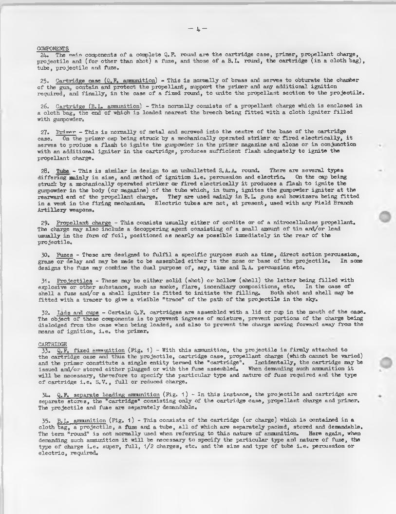
Introduction
Section i. General
Scope ...................................................................................................................................................... 1Objects 1Arrangements 1
Section 2. Definitions associated with Equipments
Guns, howitzers and mortars ........... *. ............. ................................................................... 1C lassification ................................................................................................................................... 2Means o f f ir in g ................................................................................................................................... 2Means o f in it ia t io n .......................................................................................................................... 3Safely devices ................................................. 3
Section 3. Field Branch Artillery Equipments
Loading ...................................................................................................................................................... 3
Section 4. The Round of Ammunition
Future designation and marking .......................................................................................................... 3Components ............................................................................................................................................. 4Cartridge ............................................................................................................................................. 4
Section 5. Categories of Ammunition
General ...................................................................................................................................................... 6
Chapter 2
Explosives
Section 1. Introduction
C lassification o f explosives ........................................................................................................ 7D efin itions ............................................................................................................................................. 7Uses ................................................................................................................ 10
Page
— i v —
Section 2. Propellants Page
G en era l........... . .................................................................... .................... . ................................ 10H istorica l ................................................................................................................................................. 10Burning o f a propellant ...................................................................................................................... 10Properties o f the idea l propellant ...................................................................................... ./ • • • 11Composition ................................................................................................................................... • • • 12Characteristics ......................................................................................................................................... 12Plash and Smoke ...................................................................................................................... . ••• 14Properties o f the commoner propellants ........................................................................................... 15Nomenclature ........................................................................................................................................ 15M u ltip lic ity o f propellant ...................................................................................................................... 18
Section 3. High Explosives
D efin ition ............................................................................................................................................. 18Compositions ................................................................................................................................... 20Categories ............................................................................................................................................. 20Bursting charges - i . e . shell f i l l in g s ...................................................................................... 21Constituents ................................................................................................................................... 21Code fo r H.E. f i l l in g s 21In it ia to rs (d is ru p tiv e ) ................................................................................................................. 21Constituents ................................................................................................................................... 22Intermediates ................................................................................................................................... 22T.N.T. ............. * ......................................................................................................................... 23Constituents........................................................................................................ 23
Section 4. Miscellaneous Compositions
G en era l...................................................................................................................................................... 23In it ia t in g agents (ign iferous) ........................................................................................................ 24Smoke producing substances ................................................................................................................. 21+Flare producing substances .................................................................................................................. 26Conclusions ............................................................................................................................................. 26
Chapter 3
Cartridges
Section 1. Introduction
C lass ifica tion and comparison ........................................................................................................ 27Comparison o f Q.F. (separate loading) and B.L. cartridge systems ........................................ 27Cartridge case ................................................................................................................................... 27Cartridge bag ................................................................................................................................... 28Propellant c h a rg e ................................................................................................................................... 28Charge - types ................................................................................................................................... 30Propellant proof and charge adjustment ......................................... 30
Section 2. Q.F. Cartridges
G enera l...................................................................................................................................................... 31Sub-division o f cartridges ........................................................... 31Design o f cartridges .......................................................................................................................... 31
— V
Section 3. Types of Q.F. (Separate loading) Cartridges used in Field Branch Artillery Equipments
Q.F. 25 pr. g u n ................................................................................................................................... 32Normal charges .......................................................................................................................... . . . 32Super charges ................................................................................................................................... 32Increment charges .......................................................................................................................... 34Issue and preparation ................................................................................................................. 34
Page
Section 4. B.L. Cartridges
General ............................................................................................................................................ 33Sub-division o f cartridges ....................................................................................................... 35Materials ............................................................................................................................................ 35Diameter and length .................................................................... ............. . . . . . . ............. 35Design o f B.L. howitzer and gur^/howitzer cartridges ........................................................... 36Arrangement o f howitzer and gurj/howitzer cartridges ........................................................... 36
Section 5. Types used in Field Branch Artillery Equipments
B.L. 4.5 in .gu n ................................................................................................................................. 37B.L. 3*5 in .gu n .................................................................................................................................. 37B.L. 7*2 in .h o w itz e r ......................................................................................................................... 39
Chapter 4
Means of Ignition
Section 1. Introduction
Ign ition o f the propellant charge ............................................................................................... 41
Section 2. Primers
General ............................................................................................................................................ 41Percussion - description . . . 41Action ............................................................................................................................................ 43
Section 3. Tubes
General ............................................................................................................................................. 43Percussion, S.A. cartridge ....................................................................................................... 43Action .................... 43
Section 4. Igniters
General ............................................................................................................................................ 4^
— vi—
Chapter 5
Projectiles
Section 1 Introduction Page
G en era l................................................................................................................................ 45Component d e t a i l s ......................................................................................................................................... 46P ro je c t ile s - de fin ition s ....................................................................................................................... 48
Section 2 The Shell
G en era l............. .................................................................... ................................................. ••• 50High explosive shell .......................................................................................................................... 50Shell H.E. Nosed fuzed ................................................................................................................ 50Shell, H.E. base fuzed 52Carrier, shell . . . .......................................................................................................................... 52Shell, smoke, B.E. .......................................................................................................................... 52Containers, smoke .......................................................................................................................... 54Shell plugs in coloured smoke containers ...................................................................................... 54Shell, f la r e ................................................................................................................................ 54Shell, incendiary, B.E. ................................................................................................................... 54Shell, chemical, B.E................................................................................................................................ 54Shell, star, B.E. 54Practice p ro je c tiles .......................................................................................................................... 55
Section 3 Shot
G en era l...................................................................................................................................................... 55Armour p iercing ................................................................................................................................... 55Armour piercing capped 55Practice ............................................................................................................................................. 56Proo f ...................................................................................................................................................... 56Paper ...................................................................................................................................................... 56
Chapter 6
Fuzes
Section i. Principles etc.
Introduction ................................................................................................................................... 57Forces ..................................................................................................................................................... 57Mechanical devices .......................................................................................................................... 58Other fuze components ......................................................................................................................... 64
Section 2. Types
Time fuzes ............................................................................................................................................. 66Time and percussion fuzes ................................................................................................................. 67Percussion fuzes ..................... 67Base fuzes ............................................................................................................................................. 67Proximity or variab le time (V .T .) fuzes ........................................................................................ 67
General............................................................................................................................................ 68Examination of fuzes ................................................................................................................... 68Nature of shell normally issued fuzed or plugged ................................................. 70Instructions for fuzing ........................................................................................................... 70Preparation for firing ............................................................................................................... 73Prepare shell for return to vehicle ............................................................. 74
Section 4. Care, Preservation, faulty Ammunition and Prematures
Care of fuzes ........................................................................................................................... 74Preservation................................................................................................................................... 73Faulty anniunition ................................................................................................................... 75Prematures ................................................................................................................... .-. . . . 76Defective fuzes ................................................................................................................. . . . 76Unserviceable fuzes .............................................................................................................. 76
C h ap te r 7
T ra cers and T ra c e r - and - Ign ite rs
Section 1 . General
Introduction ...................................................................................................................... 77Classification ...................................................................................................................... 77
Section 2. Tracers, Shell
Description ...................................................................................................................... 77Action ............................................................................................................ . .................... 79
Section 3 . Tracer-and-Igniters, Shell
Description .............................................................................................................................. 79Action ............................ ..................................................... ............................................. 80
Section 4 . Integral Tracers
Description .............................................................................................................................. 80
C h ap ter 8
C artrid ges , B lan k and P a p er Shot
Section 1 . Introduction
General....................................................................................................................................... 01
—vii—
Section 3. Fuzing Procedure Page
—v iii—
Section 2. Types authorised for Field Branch Artillery Equipments
Cartridge, b la n k ...................................................................................................................................Precautions to be observed when f ir in g blank ammunition ........................................................... 82Cartridge, paper shot .................................................................................................................. 82
Page
Chapter 9
Drill Ammunition
Section 1. Introduction
General ............................................................................................................................................. 83
Section 2. Components
D r il l c a r tr id g e s ................................................................................................................ 83D r i l l p ro je c t ile s ........................................................... . . . .................................................. 86D r il l fu z e s ............................................................................................................................................. 87D r i l l primers .................................................................................................................................... 87D r il l tubes - S.A. percussion .......................................................................................................... 88
Chapter 10
4.2 inch Mortar Ammunition
Section 1. Introduction
Equipment ............................................................................................................................................. 89Ammunition .................................................................................................................................... . . . 89Waterproofing and rustproofing ........................................................................................................ 90Clips sa fety pin special ................................................................................................................. 90Cover, t a i l , M.L. 4.2 in . mortar ............................................................................................... 90Spring, retain ing cartridge augmenting ...................................................................................... 90.Means o f ign ition ........................................................................................................................... 90
Section 2. Bombs
Bombs, S.B. M.L. H.E. streamline ............................................................................................... 91Practice bombs ............. ................................................................................................................. 92
Section 3. Propellant Charges
Primary cartridges ........................................................................................................ . . . . . . 92Augmenting c a r tr id g e s ...................................................................................................... . ............. 94D r i l l cartridges (primary and augmenting)...................................................................................... 94
C h a p te r 11
R eco rd s
Section i. Purpose and Application of the Lotting System Page
In trodu ction ............................................................................................................................................ 95Propellants ............................................................................................................................................ 95
Section 2; Purpose and Application of the Batching System
Introduction .................... 95Purpose o f batching .......................................................................................................................... 95Batching system ................................................................................................................................... 96Application o f batching system ....................................................................................................... 96Id en tifica tion o f batches and sub batches ........................................................................................ 97Ammunition and package markings ....................................................................................................... 98
C h a p te r 1 2
Id e n tifica tio n C o lo u rs and M a rk in g s
Section 1. Introduction
G en era l..................................................................................................................................................... 99Forms and a p p lic a t io n s ...................................... 99
Section 2. Cartridges
Metnod o f colour id en tifica tion and markings ............................................................................. 100Additional means of id en tifica tion ............................................................................................... 105Mortar cartridges 105
Section 3 . Projectiles, Fuzes and Tracers
P ro je c tiles ............................................................................................................................................ 106Stencilling ............................................................................................................................................ 110Mortar bombs ............................................................................................................................................ 117Fuzes ..................................................................................................................................................... 117
Section 4 . Packages
Method o f colour id en tifica tion and markings ............................................................................. 118
C h a p te r 13
A sso cia ted P u b lica tio n s
Associated publications ................................................................................................................. 131
— ix —
— x —
Appendix A PageVarious types and uses o f e x p lo s iv e s ............................................................................................... 133
Appendix B
Propellant compositions ........... .. ............................................................................................... 134
Appendix C
Composition o f intermediaries and in it ia t in g explosives .......................................................... 136
Appendix D
Code indicating high explosive with composition and percentages o f ingredients ............. 138
Appendix E
Details of Ammunition authorized for
Field Branch Artillery Equipments
Part i. Q.F. 25-PR. Gun Ammunition
P r o je c t i l e s ............................................................................................................................................ 14-0Cartridges ............................................................................................................................................ 140Fuzes ...................................................................................................................................................... 142Primers ............................................................................................................................................ 142Shell, Q.F. 25 pr. chemical B.E.......................................................................................................... 143Shell, H.E. streamline ................................................................................................................. 143Shell, H.E. screening smoke .................................................................................................... 144Shell, streamline, B.E. coloured smoke ........................................................................................ 145Shell, f la r e , T.R.B.E. ................................................................................................................. 145Shell, streamline, B.E. incendiary ............................................................................................... 145Shell, star ................................................................................................................................... 145Shot, A.P.C............................................................................................................................................... 145Shot, practice ................................................................................................................................... 145
Part 2. B.L. 4 .5 -inch Gun Ammunition
P ro je c tiles 145Cartridges ................................................................................................................................... 146Fuzes ...................................................................................................................................................... 146Ign iters , au x ilia ry .......................................................................................................................... 146Shell, H.E. streamline ................................................................................................................. 146Tubes ...................................................................................................................................................... 147
Page147147148148148149149150150150
150151151151152
153139164168172176180
185187189
191193
195
— x i —
P ro je c t ile s ........................................................................................................Cartridges ........................................................................................................Fuzes .................................................................................................................Ign ite rs , auxiliary ......................................................................................Shell, H.E............................................................................................................Shell, H.E. streamline ............................................................................Shell, f la re , T.R.B.E. .............................................................................Shell, B.E. incendiary .............................................................................Shell, B.E. smoke ......................................................................................Tubes .................................................................................................................
Part 3. B.L. 5 .5 -inch Gun Ammunition
Part 4. B.L. 7 .2 -inch Gun Ammunition
P ro je c t ile s .............Cartridges .............Fuzes ......................Shell, H.E. streamline Tubes ......................
Appendix F
Particulars of Fuzes
Fuze, percussion, D.A. , No.117 ...............................Fuze, percussion, D.A. and graze, No.119 .............Fuze, time and percussion, D.A., No.213 .............Fuze, time and percussion, graze, No.221 and No.221BFuze, percussion, base medium, L 1 5 ......................Fuze, percussion, D .A., No.162 ...............................Fuze rocket, 3*5 in . UK M 20 - fuzed percussion L16
Appendix G
Particulars of Primers
Primers, percussion, Q.F. cartridges, No.1 ...............................Primers, percussion, Q.F. cartridges, No.9 ...............................Primers, percussion, Q.F. cartridges, No.11 ...............................
Appendix H
Particulars of TracersTracers, sh e ll, No.2 .............................................................................Tracers, shell, No.37 .............................................................................
Tubes, percussion, S.A. cartridge
Appendix J
Particulars of Tubes
- x i i -
F ig . 1
2
3
4
3
6
7
8
9
10
11
12
13
14
15
16
17
18
19
20
21
22
23
24
25
26
27
28
List of IllustrationsP age
Types o f ammunition................................................................................................................. 5
Propellant shapes .................................................................................................................. 13
Use o f in it ia to rs , intermediaries and bursting charges ........................................ 19
Section thro* typ ica l cartridge case . . . .................................................................... 28
Typical propellant charges ............................................................................................... 29
Typical examples - separate loading cartridges - Q.P. 25 pr. ............................... 33
B.L. 4 .5 in . Gun cartridge ............................................................................................... 37
B.L. 5.5 in . Gun cartridge ............................... 38
B.L. 7.2 in . howitzer cartridge ...................................................................................... 40
Typical percussion primer .......................................................................... 42
Typical percussion tube ............................................................................................... 43
Typical C.R.H. (ca lib re radius head) design .................................................................... 47
Typical driving band and a lternative baseplates ........................................................... 48
P ro je c t ile de fin itions .......................................................................... 49
Typical H.E. (high explosive) nose fuzed shell ........................................................... 51
Typical B.E. (base ejection ) ca rrier shell ...................................................................... 53
Method o f functioning, base e jection star shell ........................................................... 55
Typical A.P. (armour p iercing) shot 56
Holding devices . . . 59
Holding devices ................................................................................................................. 60
Masking devices . . . 61
Masking devices ................................................................................................................. 62
F iring devices 63
F iring devices 64
Detonators 65
Magazine and channels ........................................................................................................ 65
H.E. shell fuze-hole plugs ............................................................................................... 69
H.E. shell suitable fo r standard fuzes, plugged with No.13 (o r L2A1) and No.3 fuze hole plugs .......................................................................................................................... 71
J
- x i i i -
P ig . 29 H.E. shell suitable fo r V.T. fuzes only, plugged with No.29 (o r L4A1 ) fuze hole plugs 72
30 H.E. shell suitable fo r V.T. or standard fuzes, plugged with No.13 (o r L2A1) fuzehole p lu g s .................................................................................................................................... 72
31 Shell, B.E. (smoke e tc . ) plugged with No.1 fuze hole plug ......................................... 73
32 Method o f setting time or time-and-percussion fuzes .................................................. 74
33 Types o f shell tracers ......................................................................................................... 78
34 Typical shell tracer-and-igniters ....................................................................................... 79
35 Typical in tegra l tracer f i l l in g s fo r shot .................................................................... 80
36 Types o f blank cartridges ......................................................................................................... 82
37 S.B. M.L. 4*2 in . mortar bcmb .................................................................... 89
38 Method o f retaining primary cartridge in S.B. M.L. 4*2 in . mortar bcmb....................... 90
39 Method o f f i l l i n g S.B. M.L. 4*2 in . mortar bomb ........................................................... 91
40 Primary cartridge and augmenting cartridge fo r S.B. M.L. 4.2 in . mortar bomb . . . 93
41 Id en tifica tion markings fo r 25 pr. c a r tr id g e s .................................................................... 101
42 Additional s ten c illin g to indicate charges designed fo r special purposes ............... 101
43 Examples o f id en tifica tion markings on B.L. cartridges .................................................. 103
44 Coloured rings, bands and stripes, e tc ., on p ro je c tiles 109
45 Typical id en tifica tio n markings fo r H.E. f i l l e d sh e ll .................................................. 113
46 Typical id en tifica tio n markings fo r smoke shell ............................................................ 114
47 Typical id en tifica tio n markings fo r f la r e shell and star shell .................................. 115
48 Typical id en tifica tio n markings fo r incendiary shell ................................................... 116
49 Typical id en tifica tion markings fo r A.P. (armour piercing) shot ................................... 116
50 Latest approved id en tifica tion markings fo r s tee l box fo r separate loading shell . . . 120
51 Latest approved id en tifica tio n markings fo r stee l box with inner con ta in ers ............. 122
52 Latest approved id en tifica tio n markings fo r wood box with inner containers ............. 124
53 Latest approved id en tifica tion markings fo r wood box with inner containers ............. 126
54 Latest approved id en tifica tion markings fo r stee l box fo r bulk packed fu z e s ............. 130
55 Shell, Q.P. 25 p r . , chemical, B.E............................................................................................ 143
56 Fuze, percussion, D.A., No.117, mark 18 154
57 Fuze, percussion, D.A., and graze, No.119B, mark 17 ................................................. 160
58 Fuze, time and percussion, D.A., No.213, mark 4 166
59 Fuze, time and percussion graze, No.221B, mark 4 169
60 Fuze, percussion, base, medium, L15A1 ............................................................................. 173
Page
P ig . 61 Fuze, percussion, D .A ., No.162, mark 3 / 3 ............................... . . . ....................... 177
62 Fuze, percussion, L16A1 (Part 1) ............................................................................. 182
63 Fuze, percussion, L16A1 (Part 2) ......................................... ............................... 183
6if. Primer, percussion, Q.F. cartridges, No.1, mark: 2 185
65 Primer, percussion, Q.F. cartridges, No.9, mark 4 187
66 Primer, percussion, Q.F. cartridges, No.11, mark i*/l .......................................... 189
67 Tracer, sh e ll, No. 2, mark 7 191
68 Tracer, sh e ll, No.37, mark 1 193
69 Tube, percussion, S.A. cartridge, mark 5 .................................................................. . 195
- x i v -
Page
f
— 1 -
NOTE
Information re la tin g to d e ta ils o f individual charges, p ro je c t ile s and th e ir packages, e tc . , w i l l be found in :-
Regs, fo r Anqy Ordnance Services Volume 4* Ammunition Pamphlet No. 6. (B. L. ammunition)Pamphlet No. 7. (Q.F. separate an.nunition)Pamphlet No. 11 Part 1 (3.5 inch Rocket Ammunition)Pamphlet No. 12 Part 3 (Ammunition fo r the Ordnance M.L.
4.2 inch Mortar)FOR DETAILS OF RESTRICTIONS IMPOSED CM THE USE OF SPECIFIC MARKS OF HJZES FOR TRAINING AND EQUIPMENTS ASSOCIATED WITH SPECIFIC MARKS OF HJZE see: -
" LIMITATIONS IN THE USE OF RJZES FOR TRAINING 1955 W.O. CODE No. 11233."
Chapter i
Introduction
Section i. General
SCOPE1 • Prim arily F ie ld Branch A r t i l le r y ammunition, but i t also embraces ammunition used in the
secondary ro le o f Anti-Tank A r t i l le r y .
OBJECTS2. Promotion o f a fu l le r understanding o f a l l aspects.
Presentation o f essentia l data fo r easy reference.Provision o f deta iled information on components.Provision o f information on assembly, purposes o f various combinations with descriptions o f
actions.
ARRANGEMENTS3° Body o f notes:- Consideration o f broad and general p rincip les.
Appendices:- (Data in tabular form.(Detailed descriptions with illu stra tion s o f current Service exponents.
4 . As indicated by the t i t l e , th is pamphlet is essen tia lly a user handbook on everything concerning F ield Branch A r t i l le r y ammunition© Although containing very complete deta iled information in the Appendices, a study o f the whole publication should not only enable the deta ils to be understood but should also assist in the understanding o f other B ritish as w ell as foreign ammunition fo r which detailed particu lars may not be ava ilab le.
Chapter i
Introduction
Section 2. Definitions associated with Equipments
GUNS. HOWITZERS AND 1DRTARS3. These are equipments which a l l have the following properties:-
(a ) That g ive p ro je c t ile s specified in i t ia l v e lo c ity and d irection o f motion.
(b ) They do so by the rapid burning o f a propellant charge in a chamber, producing gas under pressure which forces the p ro je c t ile to move along a barrel (a lso ca lled "bore" or "p ie c e " ).
_ 2 —
There are no sharp distinguishing features between guns, howitzers and mortars. Certain general d ifferences may, however, be noted.
6. Guns - These generally produce higher muzzle v e lo c it ie s , f la t t e r tra jec to ries w ith a smaller angle o f descent and have fewer charges than howitzers; apart from these there are no essen tia l b a l l is t ic d ifferences between the two.
7. Howitzers - Compared with guns these have a higher tra jec to ry , and steeper angle o f descent, with variable charges, thus enabling engagement o f targets behind intervening crests.
For r e la t iv e ly the same to ta l weight o f equipment, howitzers have a la rger ca lib re , shorter barrel and shorter range, a lower muzzle v e lo c ity , very high elevation and f i r e a heavier sh e ll w ith higher H.E. content than guns.
8. Gun/howitzer (combined weapons) - Thi3 is a gun o f a ca libre intermediate between the gun and howitzer that i t replaces and i t has a variable charge. Muzzle v e lo c it ie s are in general s lig h t ly lower than the o ld er guns but maximum ranges are usually s lig h t ly greater due p rin c ip a lly to ireproved sh ell design. Shell weights are usually lower than fo r haritzers. Thus:-
25 pr.Replaces 18 pr. gun and
4.5 inch howr.
(c a l. 3.45 inch (c a l. 3.3 inch (35 lb . shell
Range 13,000 yds. ) Range 9,000 yds.) Range 6,000 yds .)
Replaces5.5 inch gun 60 pr. gun and 6 inch howr.
(80 lb . shell (c a l. 5 inch (100 lb . shell
Range 18,000 yds.) Range 14,000 yd s .) Range 9,000 yds.)
9. Mortars - These are small, ligh t and ea s ily handled equipments propelling p ro je c t ile s w ith low v e lo c it ie s at high angles o f elevation . They are usually loaded through the muzzle, whereas guns and howitzers are loaded through the breech. They usually have smooth bores, whereas guns and howitzers have r i f le d bores. They are normally fir e d a t high angle.
CLASSIFICATION10. In the past equipments were c la ss ified by the means o f the obturation enployed. "Obturation"
is used to describe the sealing o f the rear end o f the chamber against propellant gases escaping rearwards.
1 1 . Q.F, ordnance - The propelling charge is contained in a brass or s tee l cartridge case, the case providing the means o f obturation.
There are two types:-
(a ) Fiired — The case i s firm ly attached to the p ro je c t ile and the whole assembled round is loaded as a unit. Loading i s quick but i t is not possible to vary the propellant charge without changing the conplete round.
(b ) Separate - The cartridge case is en tire ly separate and the p ro je c t ile is ranned home before the cartridge case i s loaded. The charge in the case is variab le.
12. B.L. ordnance - The charge is contained in a cloth bag, to the breech end o f which a gunpowder ig n ite r is f i t t e d . Obturation is obtained by a r e s ilie n t pad assembled on the front face o f the breech mechanism and sealing the rear end o f the chamber.
MEANS OF FIRING13. The breech mechanism o f a gun or howitzer carries the means o f f ir in g . They may be percussion
or e le c t r ic although, at the time o f w ritin g , a l l F ie ld Branch A r t i l le r y equipments have percussion breech mechanisms.
14. Percussion - The s tr ik e r o f the mechanism i s driven on to the percussion cap assembled cen tra lly in the base o f the primer or tube. The in it ia t in g conposition in the cap i s nipped on an anvil and the resultant flame ign ites gunpowder in the body o r magazine o f the primer or tube which in turn ign ites the main propellant charge*
15. E lectr ic - On contact being made the e le c t r ic current passes from the battery or dynamo, through the f ir in g p in o f the breech lock to the contact piece assembled cen tra lly in the base o f the primer or tube, along the insulated wire in the copper plug, through the iridio-platinum bridge to the small copper pole and the body o f the tube or primer, and back, v ia the gun, to the battery. The bridge becomes incandescent, ign ites the guncotton dust which, in tuns, ign ites the gunpowder in the magazine, the resultant flame ign ites the clo th ig n ite r attached to the base o f the propellant charge, sndthen the charge itse lf©

- 3 -
MEANS OF INITIATION16. Q.F. guns - The in it ia to r is contained in a primer assembled in the base o f the cartridge case.
The primer contains i t s own means o f obturation.
17. B. L, guns - The in it ia to r is contained in a small brass case known as a tube, which is loaded separately in to a chamber in the rear o f the breech mechanism. This chamber is connected by a flash channel to the chamber o f the gun.
On f ir in g , the flash passes along th is channel, on to a gunpowder ig n ite r attached to the rear end o f the cartridge, which in turn ign ites the main propellant charge.
The tube provides i t s own obturation on the Q. P. princip le and is supported by a lock working in a s lide box, which together form in e f fe c t a miniature s lid ing breech block and f ir in g mechanism.
SAFETY DEVICESiS. These are incorporated in breech and f ir in g mechanisms to prevent the gun from being fired
before the breech is fu l ly closed.
Chapter i
Introduction
Section 3. Field Branch Artillery Equipments
19. These equipments may be se lf-propelled or towed. The guns and howitzers may be o f the Q.F. type or o f the B. L. type.
LOADING20. Q.F. guns may be e ith e r fixed or separate loading, while Q. F. howitzers are separate loading
only.With fix ed ammunition the p ro je c tile is assembled to the cartridge case and loaded as one un it,
whereas with ammunition fo r Q.F. separate loading guns and howitzers the p ro je c t ile is f i r s t loaded and rammed, followed by the cartridge.
With B. L. guns and howitzers the round is always loaded separately. F ie ld Branch A r t i l le r y Q.F. and B.L. guns and howitzers are separate loading mainly because the conplete round is d i f f ic u lt to transport and handle, and also because i t a ffords fa c i l i t ie s fo r varying the propellant charge*
Chapter 1
Introduction
Section 4. The Round of Ammunition
RJTURE DESIGNATION AND MARKING21. New designs o f amnunition - A model number followed by the le t t e r "A" and a s e r ia l number w i l l
be adopted in nomenclature and markings in lieu o f a number and mark previously used to id en tify the store. Where, however, new patterns o f ex isting stores are introduced, the number ar*3/or mark w i l l continue to be advanced as heretofore.
22. Ammunition fo r new equipments - A ll references to the method o f obturation such as "B. L ." ,"Q. F ." , "R .C .L .", e tc . , w i l l be omitted from primary nomenclatures and markings. When, however, i t is required to d iffe ren tia te between two weapons o f sim ilar ca libre but o f d iffe ren t ro le arxi design, a reference to the ro le w i l l be incorporated to make id en tifica tion conplete. Typical examples although not F ie ld Branch A r t i l le r y equipments are: -
120 nm. 12 BAT.120 mm. L1 Tk.
23. Fixed ammunition (p ro je c t ile cum case) fo r new equipments - The term "round" in lieu o f "cartridge" w i l l be used to designate the conplete assembled store, in both nomenclature and markings. Where, however, new patterns o f ex istin g Q.F. fixed amnunition are introduced, the term "cartridge" w ill continue to be used.
- 4 -
COMPONENTS24. The main components o f a complete Q.F. round are the cartridge case, primer, propellant charge,
p ro je c t ile and ( fo r other than shot) a fuze, and those o f a B.L, round, the cartridge ( in a c lo th bag), tube, p ro je c t ile and fuze.
25. Cartridge case (Q.F. amnunition) - This is normally o f brass and serves to obturate the chamber o f tbs gun, contain ard protect the propellant, support the primer and any additional ign ition required, and f in a l ly , in tbs case o f a fixed round, to unite the propellant section to the p ro je c t ile .
26. Cartridge (B. L. anrounition) - This normally consists o f a propellant charge which is enclosed in a c lo th bag, the end o f which is loaded nearest the breech being f it te d w ith a cloth ig n ite r f i l l e d with gunpowder,,
27. Prinrer - This is normally o f metal and screwed into the centre o f the base o f the cartridge case. On the primer cap being struck by a mechanically operated s tr ik e r or f ir e d e le c t r ic a lly , i t serves to produce a flash to ign ite the gunpowder in the primer magazine and alone or in conjunction with an additional ig n ite r in the cartridge, produces su ffic ien t flash adequately to ign ite the propellant charge.
28. Tube - This is sim ilar in design to an unbulletted S.A.A. round. There are several types d iffe r in g mainly in s iz e , and method o f ign ition i . e . percussion and e le c tr ic . On the cap being struck by a mechanically operated s tr ik er or fir e d e le c t r ic a lly i t produces a flash to ign ite the gunpowder in the body (o r magazine) o f the tube which, in turn, ign ites the gunpowder ig n ite r at the rearward end o f the propellant charge. They are vised mainly in B.L. guns and howitzers being f it te d in a vent in the f ir in g mechanism. E le c tr ic tubes are not, at present, used with any F ie ld Branch A r t i l le r y weapons.
29. Propellant charge - This consists usually e ith er o f cord ite or o f a n itrocellu lose propellant.The charge may a lso include a decoppering agent consisting o f a sma l l amount o f t in and/or leadusually in the form o f f o i l , positioned as nearly as possible immediately in the rear o f thep ro je c t ile .
30. Fuzes - These are designed to f u l f i l a sp ec ific purpose such as time, d irect action percussion, graze o r delay and may be made to be assembled e ith er in the nose or base o f the p ro je c t ile . In some designs the fuze may combine the dual purpose o f , say, time and D.A. percussion etc.
31. P ro je c t ile s - These may be e ith er so lid (shot) o r hollow (s h e ll ) the la t t e r being f i l l e d with explosive or other substance, such as smoke, f la r e , incendiary conpositions, etc. In the case o f sh ell a fuze arel/or a sh ell ign ite r i s f i t t e d to in it ia te the f i l l in g . Both shot and sh e ll may be f it te d w ith a tracer to give a v is ib le "trace" o f the path o f the p ro je c t ile in the sky.
32. Iad3 ard cups - Certain Q.F. cartridges are assembled with a l id or cup in the mouth o f the case.The object o f these conponents is to prevent ingress o f moisture, prevent portions o f the charge beingdislodged from the case when being loaded, and a lso to prevent the charge moving forward away from the means o f ign it ion , i . e . the priner.
CARTRIDGE33. Q.F. fixed »m «in ition (F ig . 1) - With th is ammunition, the p ro je c t ile i s firm ly attached to
the cartridge case and thus the p ro je c t ile , cartridge case, propellant charge (which cannot be varied) and the primer constitute a single en tity termed the "ca rtr idge". Inciden ta lly , the cartridge may be issued and/or stored e ith e r plugged or with the fuse assembled. When demanding such ammunition i t w i l l be necessary, therefore to specify the particula r type and nature o f fuze required and the type o f cartridge i . e . S.V. , fu l l or reduced charge.
34. Q.F. separate loading ammunition (F ig . 1) - In th is instance, the p ro je c t ile and cartridge are separate stores, the "cartridge" consisting only o f the cartridge case, propellant charge and primer. The p ro je c t ile and fuze are separately demandable.
35. B.L. amnunition (F ig . 1) - This consists o f the cartridge (or charge) which is contained in a cloth bag, a p ro je c t ile , a Aize and a tube, a l l o f which are separately packed, stored and demandable. The term "round" is not normally used when re ferr in g to th is nature o f ammunition. Here again, when demanding such ammunition i t w i l l he necessary to specify the particu lar type and nature o f fuze, the type o f charge i . e . super, fu l l , 1/2 charges, e tc . and the s ize and type o f tube i . e . percussion or e le c t r ic , required.
TYPES OF AMMUNITION
T Y P IC A L Q.F. SEPARATE L O A D IN G A M M U N ITIO N
ProjectileCartridge
PRIMER PROPELLANT CLOSING CUP PROJECTILE
T Y P IC A L B.L. AM M UNITION
Cartridge
\
- 6 -
Chapter i
Introduction
Section 5. Categories of Ammunition
GENERAJjThere are four main categories o f amnunition:-
OperationalPracticeBlankD r i l l
I t is most inport suit that the d istinctions should be c lea r ly understood and recognised. Only one category o f ammunition should ever be on the gun position at ai^y one time.
37. Operational - A l l ammunition conponents in th is category i . e . , the cartridge, p ro je c t ile , fuze and tube, are "LIVE" and the p ro je c t ile is prim arily le th a l, although such non-lethal items as smoke, star and fla re shell are necessarily included.
38. Practice - Ammunition in th is category is fo r practice f ir in g , i . e . , fo r e f fe c t in simulated combat ard is provided fo r train ing in marksmanship and observation.
The conponents are "LIVE". The p ro je c t ile , however, is less le th a l than it s operational equivalent. In the case o f sh e ll or practice p ro je c tile i t may contain only a small quantity o f low explosive f i l l i n g or in the case o f shot the nose nay be truncated or may not be spec ia lly hardened.To e f fe c t economy in costs and labour such p ro je c t ile s may also be manufactured from a lower grade of material than is a requirement fo r th e ir operational versions.
Such p ro je c t ile s are designed to in f l ic t the minimum o f damage to the practice target or area, while at the same time perm itting accurate ranging to be achieved and enabling the point o f inpact to be observed.
Except fo r the p ro je c t ile , a l l other conponents are id en tica l with those used fo r the equivalent operational round.
39. Blank - This is used fo r demonstrations and saluting purposes. I t consists o f a cartridge case or bag containing only a charge, usually o f gunpowder although cord ite charges have been approved fo r some equipments.
i|0o D r i l l - A l l d r i l l amnunition is conpletely INERT and is used fo r practice in handling and d r i l l o f loading, fuzing, etc. In shape, dimensions and weight i t is sim ilar to the equivalent Service store0
- 7 -
Chapter 2
Explosives
Section 1. Introduction
CLASSIFICATION OP EXPLOSIVES41. For m ilita ry purposes explosives may be divided in to :-
Prope HantsHigh explosivesMiscellaneous, including gunpowder, pyrotechnic and other compositions that
cannot usually be detonated.
Propellants are explosives which are not normally intended to do more than explode.High exp los iw s are those that are capable o f being detonated, and are normally used fo r that
purpose. They may be sub-divided fo r gun amnunition purposes in to :-
(a ) Shell f i l l in g s , which are very insensitive and d i f f ic u lt to detonate;
(b ) In it ia t in g agents, which are very sensitive , and detonate quite eas ily ; and
(c ) Intermediaries, which are used to pick up the small but concentrated shock given by the in it ia to r and transform i t in to a su ffic ien tly vio lent wave to detonate the main f i l l in g .
DEFINITIONS42. Explosives are substances which, on being suitably in it ia ted , deconpose rap id ly, y ie ld ing a
large quantity o f gas. They are capable o f exerting a sudden and intense pressure on th e ir surroundings. The resu lting disturbance may be e ith er an "explosion" or a "detonation".
A sound knowledge o f the explosives used in F ie ld Branch A r t i l le r y ammunition is essentia l to a proper understanding o f the princip les o f care and maintenance, as i s also some knowledge o f the metals used fo r explosive containers such as shells , magazines, e tc .
43. Explosion - This may be regarded as a rapid combustion, which occurs in the absence o f atmospheric oxygen, and is characterised by the evolution o f heat, flash and sound, and by the rapid deconposition o f the substance, forming large quantities o f gets. The rate o f deconposition is , however, comparatively slow when compared with the extremely rapid deconposition o f detonation.I t may be between 0.3 and 300 metres per second and depends to a great extent on the surrounding tenperature and pressure. When an explosive such as cordite i s ign ited i t bums from the surface inwards in p a ra lle l layers w ith a ve lo c ity which depends on the pressure, but which, even urder several thousand atmospheres, never exceeds a few metres per second. The ign ition is conminicated from layer to layer by the heat generated, and the hotter the explosive is before ign ition , the less heat is required to ign ite i t and the less time i t takes to bum from layer to layer.
Thus w ith an explosion, the explosive is converted into gas by burning which progresses conparatively slowly and regu larly and exerts a sustained pressure on the container. This pressure builds up u n til "something goes".
In the case o f a propellant charge, th is i s the p ro je c t ile which is forced up the bore o f the gun, neither p ro je c t ile nor gun being damaged.
I f the explosive is confined in a sealed container, such as a sh e ll, th is w i l l fracture at i t s we alee st points in to a few large fragments. The actual fractures are conparatively clean and normal to the surface.
The principa l explosives o f th is type are the cord ites, n itroce llu lose propellants and gunpowder. These explosives i f in su ffic ien tly confined w i l l only bum, and th is fa ct is made use o f in various powder tra ins fo r fuzes, tracers etc.
44. Detonation - With a detonation the conversion into gas is by a disruptive ard. almost instantaneous wave action which shatters the container into a large number o f small fragments tra ve llin g at great speed and therefore with great penetrative power. These fragments are themselves evidence o f the disruptive action, being jagged and sp lit .
The explosives that are capable o f being detonated are known as high explosives. Unless there is e f f ic ie n t in it ia t io n and transmission o f the detonating wave, however, a p a rtia l detonation, explosive, or burning only w i l l resu lt.

- 8 -
45. V e lo c ity o f detonation - This varies from 3,000 metres/sec. to over 8,000 metres/sec. with Service high explosives. Rates fo r some o f the conraoner high explosives are given below:-
DESIGNATIONV. o f D. metres/sec
Melting point °C
Ign ition point °C
Fulminate o f mercury 4,500 at density 3*3 gn/c.c. - about 170°Lead azide 4,500 n 3.8 N - " 350°Amatol 80/20 5,080 n 1.5 N - 235°Guncotton, wet 5,500 n 1.23 n - 187°Torpex 6,850 M 1.73 n -T.N.T. 6,900 n 1.57 It 81. 1° 240°P ic r ic acid 7,250 ii 1*63 N 121. 6° 250°Guncotton, dry 7,300 it 1.15 It - 187°C.E. 7,300 n 1.5 It 129.1° 180°N i t roglycerine 7,750 it - 13° 188°P.E.T.N. 8,100 ii 1.7 It 141° 145-150°R.D.X. 8,400 ti 1.7 It 203.5° 213°
The ve lo c ity o f detonation is not g rea tly a ffected by external conditions unless these are extreme. A ir temperature has l i t t l e or no e f fe c t . Increase o f confinement has a s ligh t e f fe c t only, provided that the confinement i s su ffic ien t to ensure couplete detonation. In very insensitive explosives, however, the propagation o f detonation may not be maintained under ligh t confinement.
The ch ie f factor a ffe c tin g ve lo c ity o f detonation i s the density o f the explosive. Up to a maximum lim it increase in density means increase in ve loc ity .
e . g . , P ic r ic acid density 1.3 g r./ c .c . rate 5,980 metres/sec." 1.5 w " 7,110 •" 1.63 " n 7,250 "
This i s the lim it fo r p ic r ic acid and further increase in density w i l l not a ffe c t the rate o f detonation. I t should also be noted that increase in density produces also a decrease in s e n s it iv ity , e .g . T.N.T. crysta ls are used as an intermediary, while cast T.N.T. i s used as a bursting charge.
I t has been found that the e ffe c t o f detonation is most v io len t in the d irection in which the detonating wave i s tra ve llin g . I t fo llow s, therefore, that both in the design and use o f detonators th is point should be borne in mind. The most e f fe c t iv e part o f a detonator i s the closed end.
46. E ffec t o f an a ir gap - I f an a ir gap i s introduced in to a detonating system the detonation wave, in jumping the gap, loses energy, and the amplitude o f the wave fa l l s o f f in proportion to the size o f the gap. I f the fa l l in g o f f is great enough, the detonation wave may fade out a ltogether, and even i f the gap is so small that the wave passes over, i t may have lo s t so much o f i t s energy that complete detonation o f the remainder o f the explosive w i l l not occur, and a 'p a r t ia l ' detonation or 'explosion only* w i l l resu lt.
I t is therefore very important to avoid a ir gaps in a detonating system and to maintain the stress supplied by the in i t ia l detonation above the necessary c r it ic a l value, since detonation breaks down when the amplitude o f the wave fa l ls below th is c r i t ic a l value. A ir gaps are unimportant in an explosion, as the flash crosses the gap eas ily . S ligh t gaps between the conponents o f in it ia t in g systems are unavoidable, and therefore in it ia t in g and intermediary f i l l in g s should have an anple margin o f power.
47. Sensitiveness to blow and fr ic t io n - The property which a l l explosives possess o f being brought to explosion by blow or fr ic t io n is known as "sensitiveness" or "s en s it iv ity " , the former designation being used in Service lite ra tu re . This property is o f great iimportance as i t indicates the uses to which an explosive may sa fe ly be put and i t determines the precautions which must be taken during i t s manufacture, handling and transport. Very sensitive explosives are required fo r use in percussion caps and detonators, while those which may be used as bursting charges fo r sh e ll and have therefore to withstand the considerable shock o f discharge from a gun must be very insensitive.
48. In it ia t io n - Explosives are started o f f by " in it ia to rs " . These are ign ited by a d irect blow, fr ic t io n or flame, and are used fo r starting the action o f combustion, explosion and detonation.
For starting combustion or explosion, a flame only i s required and such an in it ia to r i s termed "ign iferou s".
- 9 -
Where a detonating wave i s required, however, a "d isruptive" in it ia to r is necessary. This starts by burning, but quickly builds up to detonation. The detonating wave from a disruptive in it ia to r is seldom powerful enough in i t s e l f to set o f f the comparatively stable high explosive used as the main f i l l in g or bursting charge o f a sh ell and consequently an "intermediary" or "exploder" is interposed. (The American term "booster" i s synonymous with "exp loder").
Disruptive in it ia to rs and intermediaries are classed as high explosives.
49. Light - This is objectionable in the case o f propellants but is o f use in locating shell and bomb bursts, and in tracer compositions, which enable the tra jectory o f a p ro je c t ile to be observed thereby assisting ranging, and also fo r star shell and illum inating compositions. In th is application gas pressure is redundant and may even be injurious so that compositions are desirable which give only so lid products o f combustion. Further, hot gases from burning or explosion are ionised, i . e . , possess e le c tr ic a l conductivity, so that tracers and igniferous self-destruction elements on shell are found to prohibit the "aiming" o f radio proximity fuzes. Ionized gases, however, from sh ell or bomb bursts g ive radar echo which is much greater than that from the p ro je c tile in f l ig h t alone. This e f fe c t assists ranging at night or in fogQr weather.
50. Sound - A l l explosions or detonations g ive r ise to sound waves ( i . e . , longitudinal waves) in the a ir and consist o f successive compressions and rarefactions. Where these are o f large amplitude as when a charge o f high explosive is detonated, they give r ise to b last and suction e ffe c ts which may do considerable damage to m aterial and personnel. The b last from the muzzle gases o f a gun whichmay at the muzzle attain magnitudes o f the order o f 4 tons per square inch, can produce harmful physiological e ffe c ts unless personnel and particu larly th e ir ears are adequately protected. This e f fe c t may be a great annoyance in "staggered" battery positions where one gun may be f ir in g nearly over another.
Sound waves freon ordnance or shell bursts are made use o f in sound ranging and the location o f h os tile ba tteries.
51. Compatibility - I t is c le a r ly o f great importance that explosives shall not in teract with either(a ) other explosives with which they may be in contact or (b ) th e ir containers. This c r iter ion is known as com patibility. The assessment o f com patibility is not always easy, fo r small changes in conditions may grea tly a ffe c t the resu lt. Thus, mercury fulminate i s quite stable towards copper a t ordinary temperatures when dry, but w i l l decompose when placed in copper caps in the presence o f moisture. I t is possible to obtain an assessment o f com patibility by putting the store concernedon clim atic t r ia l .
Incom patibility may lead to dangerous conditions, or to changes in explosive or b a l l is t ic performance. Thus, lead azide in copper, in the presence o f moisture, may decompose with the formation o f a very sensitive copper azide. N itroglycerine vapour from a propellant is absorbed by ce llu lo id . Thus i f a propellant which contains n itroglycerine is f i l l e d into ce llu lo id containers (e .g . mortar secondary cartridges) the n itroglycerine migrates from the propellant to the ce llu lo id , and a f a l l in b a ll is t ic s resu lts. This also happened in the case o f the ce llu lo id cups which were, formerly, used fo r sealing tracer cav ities in the bases o f shells. The ce llu lo id cups softened and dropped out. P ic r ic acid, fo r example, reacts with certain metals, especia lly lead, to give sensitive sa lts . Stringent precautions, therefore, have to be taken by specifying "lead freedom"(not more than 0.03 per cent lead) in any store or ingredient which may possibly be used with p ic r ic acid or sh e llite .
Since i t is essen tia l, in the B ritish services, that stores should remain safe and e f f ic ie n t fo r a t least 25 years, com patibility mast always be borne in mind when considering the design or storage o f ainrrunition. The fo llow ing are examples o f incom patib ility: -
(a ) Carbamite softens paint. The in teriors o f wooden boxes in which bulk cord ite i s stored are, therefore, l e f t " in the white".
(b ) Nitrous gases from the decomposition o f propellants, and ammonia from p ic r ite propellants both cause "season cracking" o f cartridge brass. I t i s necessary, therefore, to protect the in terio rs o f cartridge cases by shellacking before insertion o f the propellant charge in the f i l l i n g factory.
(c ) Ammonium n itra te , especia lly when damp, is lia b le to attack metals. The in ter io rs o f sh e ll, mortar bombs, e tc . therefore, which are to be f i l l e d amatol or other ammonium n itrate mixtures, must be protected, before f i l l in g , by means o f copal varnish.
(d) T.N.T. is incompatible with a lk a li.(e ) Ordinary vulcanised rubber contains sulphur, which read ily attacks brass (cartridge brass
and primer bodies) to give black copper sulphide, CuS.( f ) P.E.T.N. i s incompatible with amatol.(g ) T e try l (C .E .) is incompatible with gunpowder.(h) Lead azide is incompatible with copper and with shellac varnish.( j ) P ic r ic acid is incompatible with bleaching powder.
-1 0 -
52. Compositions - In addition to the propellants and high explosives, there is a va rie ty o f compositions, ch ie f among them being gunpowder. This is the oldest known explosive, and although no longer used as a propellant or le th a l bursting charge, is used, extensively and forms v i t a l links in almost every ammunition component. Other compositions include igniferous in it ia to r s , illuminants fo r star shell and tracers and smoke producers.
USES53 • A diagrammatic representation o f the various types and uses o f explosives is at Appendix A.
Chapter 2
Explosives
Section 2. Propellants
GENERAL54. These are materials which when ign ited in the gun chamber, burn smoothly, exert pressure on the
base o f the p ro je c t ile thereby causing i t to move up the bore o f the gun. The pressure developed depends upon the rate at •which the propellant burns. This can be controlled by the selection o f the s ize and shape o f the pieces o f which the propellant charge i s made up, by the composition o f the propellant and by the amount used.
These factors have to be considered in re la tion to the s ize o f the gun chamber, the dimensions o f the bore and the weight o f the p ro je c t ile . Thus, when estimating a charge to g ive a certain muzzle ve lo c ity without exceeding a specified pressure, the smallest possible s ize o f propellant is selected, in order to get the fo llow ing advantages:-
(a ) Greatest possible e ffic ien cy , i . e . , the smallest possible charge weight, in order to assis t loading and packaging.
(b ) Position o f " a l l burnt" as fa r back as possib le.
Propellants are made in various shapes e .g . cord, ribbon, tubular and s lo tted tubular. They are also made in granular form, in th is form they may be tubular or multi tubular. (See P ig . 2)
Id ea lly only one nature o f propellant should be used in one equipment, but th is is not possib le at present.
HISTORICAL55« The orig in o f propellants and explosives is rather obscure and is bound up with the discovery
o f methods o f purify ing sa ltpetre. The f i r s t propellant discovered, in the 13th century, was gunpowder which is a mixture o f sa ltpetre, sulphur and charcoal. Gunpowder was used as a propellant u n til the la te 19th century and the development o f modem propellants can be said to date from attempts in 1845 by Schonbein to use n itroce llu lose (guncotton) in place o f gunpowder. The n itroce llu lose was manufactured by the action o f n it r ic acid and sulphuric acid on cotton. In 1884 V ie l le produced a propellant using only n itroce llu lose , hot ro lled in to sheets and cut in to squares which was ca lled "Poudre B". Nobel produced a sim ilar produce by mixing n itroce llu lose and n itro glycerine under water, hot ro llin g the resultant paste and cutting i t in to small squares, th is was ca lled B a l l is t it e . In 1888 Avel used a mixture o f n itroce llu lose, n itroglycerine and mineral j e l l y gela tin ized by acetone. This was pressed in to cords and dried to remove the acetone used in the process. Being in cord form i t was ca lled cord ite and was adopted fo r use by the Services in 1891 in place o f gunpowder. Since th is date e ffo r ts have been concentrated on producing improvements such as the production o f more power in a smaller space, the use o f s tab ilise rs to increase storage l i f e and the inclusion o f ingredients to decrease the smoke, flash and heat produced.
BURNING OF A PROPELLANT5&« The main characteristics o f the burning o f a propellant a re :-
(a ) burning is purely on the surface and normal to the surface;
(b ) the rate o f burning, increases with pressure on the surface. I t is p ra c tica lly proportional to pressure, though i t departs from lin e a lit y at high pressures.
As the propellant starts to burn, gas is generated and the pressure in the chamber o f the gun r ises u n til the p ro je c t ile starts to move. The pressure at which movement commences is known as '"shot start pressure".
- 11—
A fter th is pressure continues to r ise u n til the increase o f volume behind the p ro je c t ile counter balances the r ise o f pressure caused by the evolution o f gas. At th is point we get the point o f "maximum pressure", a fte r which the pressure fa l ls o f f slowly u n til a l l the propellant has been consumed. The pressure w i l l then f a l l more rap id ly because o f the expansion and heat losses, nevertheless the ve lo c ity w i l l continue to increase u n til the pressure o f the gases has ceased to act on the base o f the p ro je c t ile , i . e . shortly a fte r i t has l e f t the nuzzle o f the gun.
The point o f maximum pressure is reached very quickly, and the maximum acceleration o f the p ro je c t ile results in very great "set-back" e ffe c t on the p ro je c t ile . This e f fe c t is important in the design o f shell and fuzes.
57• A l l burnt position - The position reached in the bore o f a gun by the p ro je c t ile at the moment when a l l the propellant charge has been consumed is known as the " a l l burnt" point.
The gun is capable o f producing i t s maximum muzzle ve lo c ity when the optimum power is used and th is usually means a large size o f propellant, large charge weight, a forward position o f " a l l burnt", and higher muzzle pressures. The propellant however, is used most e f f ic ie n t ly when " a l l burnt" is w ell back, and th is is the usual position . I f the " a l l burnt" point is too near the muzzle, irregu lar b a ll is t ic s are caused. While i f i t is outside the muzzle we not only waste propellants, but also increase the r isk o f burning pa rtic les ign itin g material near the gun.
PROPERTIES OF THE IDEAL PROPELLAflT58" Rate o f burning - I t must be regular and rea d ily con tro llab le , thus in order that the muzzle
ve lo c ity shall be uniform from p ro je c t ile to p ro je c t ile and so enable the gunner to h it a selected target, the rate o f burning and the amount o f heat and gas produced by a propellant mist be as uniform as possible. This i s usually attained by using a co llo id a l ( i . e . gela tin ized ) explosive o f a uniform conposition which can only bum from the surface, layer to layer. The amount o f surface exposed governs the rate at which i t can bum e .g . when in cord form the size o f cord w i l l determine the rate o f burning since, fo r a given charge weight, a large number o f small cords w i l l o f fe r more burning surface than a few large cords. The area o f the burning surface can be further increased by changing the shape o f the propellant, e .g . ribbon, tubular, slo tted tubular and granular. By th is method i t is possible fo r a propellant o f iden tica l conposition but o f d iffe ren t shape and size to be used in weapons varying from revolvers to heavy guns. D ifferent burning characteristics can a lso be obtained by changing the ingredients or the proportions used in the manufacture o f the propellanto
59. I t must not detonate - Propellants are made from ingredients some or a l l o f which are capable o f being detonated. I t is essen tia l that there should be no tendency fo r the resultant propellantto detonate when used under the conditions fo r which i t is introduced.
60o I t should be free from flash - This is inport ant from a ta c t ic a l point o f view as muzzle flash w i l l divulge the position o f an active gun especia lly at night. Freedom from backflash is also inportant as there would be danger to the guns crew and also the r isk o f ign itin g cartridges or other inflammable material in the v ic in ity o f the breech.
The cause o f muzzle and backflash is the formation o f incompletely burnt gases which are at a high tenperature. These gases ign ite on coming in to contact with the outside a ir a fte r the p ro je c t ile has l e f t the muzzle or when the breech is opened.
61. I t should be smokeless - This is as important as freedom from flash from a ta c t ic a l point of view. In addition excessive smoke is inconvenient when a gun is being layed on a visual target, the smoke may obscure the view o f the gun crew and make observation d if f ic u lt .
62. I t should not leave residue - Hot smouldering fragments o f incompletely burnt propellant or charge bags are obviously dangerous i f they remain in the chamber or bore o f a gun. So lid residue fouls the bore and increases erosion.
63. I t should not cause erosion - Erosion o f the chamber and the bore o f a gun is due to the washing action o f the hot gases; i t is p a rtly caused by th e ir high ve lo c ity but mainly by th e ir high tenperature. The rapid heating and cooling to which the bore o f a gun is subjected further tends to disintegrate the surface metal. Therefore the propellant should burn as coo lly as possible consistent with obtaining the required b a ll is t ic s .
64. I t must not break up - The sticks or granules o f propellant, which make up a charge, must not break up during burning as th is would cause a change in area o f the burning surface and hence irregu lar b a ll is t ic s .
65. I t should be easy to ign ite - Most propellants are not easy to ign ite and the use o f gunpowder ign iters is almost universal. The ign ition o f the propellant must not be so d i f f ic u lt that the ign ite r has to be large in size.
— 12 —
66. I t should be stable in storage and transport - The explosives used in propellants undergo a continuous process o f decomposition. With modern propellants the rate o f th is decorrposition is very slow indeed and the progress o f decomposition is determined by the periodical examination o f a l l propellants stored in bulk together with that made up into charges.
Decomposition i s accompanied by an evolution o f heat and the formation o f fre e acids. I f the heat is not dissipated and the free acids are not neutralised decomposition is accelerated and may eventually lead to spontaneous ign it ion . Cool dry storage and the addition o f s ta b ilize rs , which neutralise the free acids, are the best means o f prolonging the l i f e o f the propellant.
67. I t should be insensitive to shock and fr ic t io n - The propellant should be able to be handled and transported with safety both in bulk and when made up into charges.
68. I t should be unaffected by moisture and temperature - The general e ffe c t o f moisture, i f absorbed by the propellant, is to a lte r the density o f loading which w i l l cause e rra tic shooting.In addition damp may cause in teraction between the explosive and i t s surroundings leading to in s ta b ility .
Exposure, fo r short periods, to extreme temperatures may lead to physical changes in the propellant which are usually o f a temporary nature.
69. I t should not be too bulky - The propellant must be powerful so that the required charge and the chamber o f the gun do not need to be excessively large.
COMPOSITION70. Particu lars o f the basic propellants in current use fo r airmunition are given in Appendix B.
A ll modern propellants used in the B ritish Service contain n itroce llu lose , and when based onth is alone, are known as "single-base” types or "n itroce llu lose cannon powders” . (The American term "cannon powder” , which is synonymous with "propellant” is misleading in that these propellants are not powders as normally understood).
B ritish "double-base” type propellants contain n itroglycerine in addition to n itroce llu lose and are known as "co rd ites ". The cordites are often further described as "mineral je l ly " or "carbamite" according to the s ta b il iz e r used.
P ic r ite propellant or "flash less cordites" as they are sometimes ca lled (e .g . cord ite N & NQ) are a "double-base" type o f propellant containing in addition to the normal ingredients a high proportion o f nitroguanidine (p ic r ite ) •
The ce llu lose employed in manufacture may be derived from cotton, wood, grass, o r other pulp. This is n itrated and ge la tin ized . A s ta b iliz e r is added to reduce the natural decay o f such mixtures, and a flash in h ib ito r incorporated (w ith or without a moderant) where flashlessness is required. During manufacture, the propellant in the form o f a dough is generally pressed through dies which determine the shape o f the cross-section. This dough emerges sim ilar in form to macaroni and i s afterwards cut in to long "sticks" or very short lengths ca lled "granules".
CHARACTERISTICS71 • The temperature o f the propellant charge before ign it ion a ffec ts the b a ll is t ic s obtained.
The range tables, which are compiled fo r the Service p ro je c t ile at a standard muzzle v e lo c ity , include data to show the variation in shooting which may be expected due to variation in charge temperature.
High charge temperatures lead to higher chamber pressures which may be excessive in extreme conditions. Accordingly i t i s correct d r i l l to keep charges as reasonably cool as possib le and particu la rly to keep ready-use ammunition at as uniform a temperature as possible to ensure consistent shooting.
72. The heat conductivity o f propellants is low, with the consequences that charges tend to lagbehind th e ir surroundings in regard to change o f terrroerat ur e . This presents some problems in thedetermination o f the e f fe c t iv e chaige temperature, p a rticu la rly with Q.F. anraunition and is one of the main reasons why Q.F. ammunition should not be subjected to d irect sunlight. Apart from this consideration, d irect sunlight may also in extreme cases produce changes o f b a ll is t ic s , although this is un likely with modem propellants as compared with the older ones. The method o f measuring charge temperature is dealt with in training manuals.
73. Lotting - Propellants are produced in " lo ts " which are checked fo r homogeneity and performance. Cartridges made up from one lo t (as is indicated by the lo t or batch marking) should therefore be iden tica l in character and performance in a given gun.
With modem propellants, reasonable age does not m ateria lly a ffe c t b a ll is t ic s .
7k» Colour - The colour o f most propellants varies from a lig h t amber and various shades o f blue and green to black. In the case o f cord ite , the colour deepens with age.
- 1 3 -
75. Shape aid size - The shape and s ize or form o f the propellant determines the rate o f burning and provides the necessary control to su it d iffe ren t ca libres and barre l lengths as w e ll as varying charges. Generally, the smaller the surface area exposed the slower the rate o f burning. The cross sections most comnonly used are shown in P ig. 2.
- 1 4 -
(a ) Stick or cord propellant - With th is , as with tube (b ) below, the length is great in conroarison with the diameter and 'end e f fe c t ' i . e . , burning from the ends, is ignored. Burning may be considered, therefore, as the continued diminution o f a c ircu lar cross section, hence, other things being equal, the rate o f evolution o f gas is greatest at f i r s t and fa l ls b f f during burning,, Such a propellant is ca lled degressive, and tends to g ive a rather "peaky" pressure-space curve. In order to overcome th is , there were introduced:-
(b ) Tubular propellant - Here the cross section is a ring. In theory, th is form is neutral, fo r the combined perimeters o f the external and in ternal surfaces should remain constant during burning. In p ractice , th is form is s lig h t ly degressive, owing to slower and irregu la r burning o f the interior® Further, pressure builds up inside the tubes, which may burst, particu la rly i f they are in i t ia l l y in a state o f stress. To overcome these defects, which are pa rticu la rly noticeable with the more b r i t t le p ic r ite propellants, the slo tted tube form was introduced® This is a tube which is s l it a l l the way down. The sticks, th erefore, are less l ik e ly to be in a state o f mechanical stress before firing®As soon as the propellant starts to bum i t opens up and re lie ves in ternal pressure in the sticks®
(c ) Multitube propellant - This consists o f short cy lin d rica l grains, whose length is about 2.1/2 times th e ir diameter. The cross section shows a central hole, which i s surrounded symmetrically by six equal holes. Each hole is approx, 1/lOth the to ta l diameter o f the grain® As the grain burns, i t s to ta l surface increases (seven holes increasing as one external circumference decreases) so that th is shape is ' progressive*. For a given maxinum pressure, the maximum is reached rather la te r in shot tra ve l than with cord o r tube and the pressure is more sustained, thus g iv ing a higher muzzle ve lo c ity . But a fte r tte webs have burnt through, the grain breaks up in to s ix in ternal and six external 's l iv e r s ' which are h ighly degressive so that " a l l burnt" is rather e a r l ie r than fo r cord or tube.
FLASH AND SMOKE76. The" gases released at the muzzle on f ir in g a gun may cause flash or smoke. Since they are
released with considerable force (muzzle b la s t ), they may disturb dust on the ground giving r is e to a dust cloud. Smoke, flash and dust are undesirable, since they resu lt in the loss o f concealment and, pa rticu la rly in d irect shooting, in terfere with laying and the observation o f tracer.
Flash is the ign it ion o f hot gases in contact w ith the oxygen o f the atmosphere.
77. Flash may be prevented by :-
(a ) Making the propellant cooler burning so that the liberated gases are not hot enough to combine w ith the atmospheric oxygen.
(b ) Including p ic r ite in the propellant. When burnt th is substance g ives o f f a large amount o f nitrogen which d ilu tes the concentration o f carbon monoxide and hydrogen and prevents i t s forming an ign itab le mixture with the atmospheric oxygen.
(c ) Adding certa in m etallic sa lts (e .g . o f potassium) to the propellant. This slows down the process o f reaction o f the carbon monoxide and hydrogen with the atmospheric oxygen.
78. The equally undesirable features o f flash and smoke, although governed to a major extent by the actual conposition o f the propellant, are also a ffected by the ign it ion and the p ecu lia r it ies o f the gun and charge. Unfortunately, a decrease in fla sh can sometimes only be achieved a t the expense o f an increase in smoke, and v ice versa. In fa c t , the term "fla sh less" (o r "smokeless") as applied to a particu la r nature o f propellant expresses the intention but not necessarily the resu lt, i . e . , a charge described as flash less may in some guns and some conditions give a fu l l flash .
The products o f combustion o f a flash less charge contain carbon monoxide and are therefore poisonous.
79. Although considerable progress has been made, cartridges have not yet been produced which are both smokeless and flash less. The problem is greatest with the high performance guns, i . e . , those g iv ing a high MV and working at a high chamber pressure.
The present p o licy i s : -
(a ) For ind irect f i r e weapons (F ie ld Branch and H.A.A. in the ground ro le ) flash is notacceptable because o f enemy flash spotting at night0 Smoke is therefore accepted as thelesser e v i l .
(b ) For d irect f i r e weapons i . e . anti-tank, e tc . , smoke is unacceptable fo r reasons o f 103s o f concealment and interference with laying and the observation o f tracer. Flash is accepted as the lesser e v i l , although every attenpt is being made to reduce i t .

- 15-
PKOPERTIES OF THE COMMONER PIUPELLANTS80. The ch ief characteristics and points o f d ifference o f the main types o f propellants are shown in
the follow ing tab le :-
TypeModem double-base (flash in g ) cordites
e .g .
P ic r ite (fla sh less ) propellants
e .g .
Early singlebase propellant
e .g .
Modem single-base (fla sh less ) propellant
e .g .
Propellant w, m SC, HSC N* NQ NOT NH FNH
Form Completely co llo ida l or gelantinous. Used in " sticks'* and bundled.
Not en tire ly co ll short lengths or(N, may also be used in s tick s ).
oidal and s ligh tly b r i t t le . Used in ve iy "grains'*. F illed loose.
Ign ition F a ir ly easy with moderate quantity o f gunpowder.
D if f ic u lt . Requires more gunpowder than W or WM.
F a ir ly d i f f ic u lt . D if f ic u lt .
Smoke L i t t le Considerable, but partly due to more powder fo r ign ition .
Moderate Considerable, but pa rtly due to more powder fo r ign ition .
Flash Considerable, particu larly in high pressure guns.
P ra c tica lly none in many guns, but may be considerable in high pressure guns.
Considerable P ractica lly none in many guns, but may be considerable in high pressure guns.
Erosion Moderate SC moderate HSC considerable.
L i t t le Moderate Moderate but lessNUT
L i t t l e
Power(inverse of bulk)
Good SC Good HSC Better
Low Moderate Moderate but lessNOT
Low
Regularity o f burning
Good Should be good Moderate Good
Fouling L i t t le Rather bad. Frequent cleaning o f mechanisms is desirable.
Fa ir Rather bad. Frequent cleaning o f mechanism is desirable.
Resistance to ageing
Good Bad Good
E ffec t o f moisture
Slight Very s ligh t Bad Poor
E ffect o f heat
Very s ligh t except at extreme high tearperature.
Bad Promotes loss o f residual v o la t ile solvent giving change in b a ll is t ic s . Storage in hermatically sealed containers desirable,
E ffect of cold
Exudation o f n itro glycerine may take place at low temperatures.Not l ik e ly normally.
P rac tica lly n il None
NOMENCLATURE61 . Nature - The nature o f the propellant is indicated by a le t t e r or combination o f le t te rs , but
the significance o f a particu lar le t t e r may vary according to i t s position in the combination.The various le t te rs used are shown in the fo llow ing paragraph. Some o f the le t te rs describe
propellants not in use with F ield Branch A r t i l le r y ammunition, but a complete l i s t is given in order to complete the picture and provide fo r any future developments.
- 1 6 -
The use o f three figu re s izing giving dimensions to one-thousandth o f an inch or two figure s izing giving dimensions to one-hundredth o f an inch is related to the composition and production process o f t ie propellant.
The fo llow ing are examples o f propellant id en tifica tion code le t te rs combined with shape le tte rs and s ize figu res :-
Cordite Granular Id Powders
Cord (s t ick ) Ribbon Tubular S lotted Tubular
AN .048 N .048 NQ .030sc .048 w .057WM .017
NQ/R 014 x 048 SC/T 198-100 W/T 206-100 Wfc/T 211-100
V s 164-048NO/S 164-048
FNH 057 FNHP 038 NH 030
82. Id en tifica tion code indication nature o f propellant - The follov/ing code is used in the marking o f gun and mortar cartridges.
DESIGNATION OF PROPELLANT
(N itroce llu lose powders)
IDENTIFICATION LETTERS, ETC.
N itrocellu lose r i f l e powder Mk. 8Z. NCEP ( 8Z)Neonite No. 9 NRN9Neonite No. 12 NRN12NOT powder (U.S. NC(pyro) i.e.1914-18 production) 1CTNH powder (U.S. Hercules NH) NHNH powder (U.S. Dupont NH - la te r M.6) NHFI® Powder (U.S.Dupont FNH - la te r M.1) FI®FNH powder (U.S. Hercules FNH - la te r M.4) FNHFNHP powder (U.S. Dupont production fo r U.K.) FNHPFNHP powder (U.S.Hercules production fo r U.K.) FNHP
(N itroce llu lose - n itroglycerine compositions)
B a ll is t it e B BAL.BCordite ACordite AN ANCordite ASN ASNCordite CD CDCordite HSC HSCCordite KSCK HSCKCordite 153 mCordite MD mdCordite MDC MDCCordite RDB RDBCordite SC SCCordite W wCordite WM WMM4X (U.S. Dupont) M2+X81 mm. mortar powder (U.S. Hercules) KERC81 rrrn.FNHDB (U.S. Hercules FNH - la te r M.2) FNHDBFNHDB (U.S. Hercules FNH - la te r M.5) FNHDB
(N itroce llu lose - n itroglycerine - p ic r ite compositions)
Cordite NF NFCordite N NCordite NQF NQFCordite NQ NQCordite NP NP
UNE
- 1 7 -
(N itrocellu lose - n itroglycerine - p ic r lte compositions)
Cordite NQFP NQFPCordite N2P N2PCordite MNF MNFCordite MNQF MNQFCtordite MNF2P MNF2P
83. American propellants - The B ritish nomenclature and id en tifica tio n le tte rs fo r U.S. gun propellants are not the same as those now used by the Americans. In am plification o f the corresponding U.S. designations given in para. 82 the fo llow ing is a b r ie f surnnary o f the positions:-
NCT These le t te r s adopted by us in the 1914-18 war was to ind icate "n itrocellu lose tubular", have not been used in the U.S. where the propellant was designated "powder propellant n itroce llu lose (pyro )" and is now obsolete.
NH These le tte rs were in use in the U.S. to mean "non-hygroscopic* in the designation o f both Hercules and Dupont smokeless cannon powders when we began to import these propellants in 1940. We used the le t te rs in the designation "NH powder" which we adopted fo r both.Later only the Dupont powder was produced and in time became known in the U.S. as "powder propellant M.6". We have continued to use the designation '1® powder".
FNH These le tte rs were in use in the U.S. to mean "fla sh less , non-hygroscopic" in thedesignation o f both Hercules and Dupont flash less cannon powders when we began to import these propellants in 1940. We used the le t te rs in the designation "FNH powder" which we adopted fo r both. Later, tinder American nomenclature, the Hercules powder became "powder propellant M.4" and the Dupont, "powder propellant M.1" and the le t te rs FNH were used only as marking to indicate a flash less performance in a given gun irrespective o f the composition. In time only the M.1 was produced and th is we have continued to c a ll "FNH powder".
FNHP These le tte rs have not been used in the U.S. nomenclature but were adopted in B ritishnomenclature fo r Hercules and Dupont flash less cannon powders specia lly produced to meet a B ritish requirement in 1940. Later only the Dupont powder was produced.
FNHDB These le t te rs have not been used in the U.S. nomenclature but were introduced in the B ritish designation o f the two Hercules double base flash less cannon powders imported during the 1939-45 war. Under American nomenclature these propellants were la te r designated "powders propellant M.2 and M.5". Neither i s used in B ritish ammunition and the le tte rs have remain unchanged.
84. Propellant shape le t te rs and s ize figures - With certain exceptions, the designation o f a propellant includes also the shape and the s ize dimensions in which the propellant is produced.The exceptions are the propellants which are normally in the fin e r granular forms and comprise:-
Nitrocellulose r i f l e powder Mk. 8Z Neonites No. 9 and No. 12 B a llis tite MWC81 mm. mortar powder
The shape ( i . e . physical form) (F ig . 2) in which the propellant has been produced i s normally indicated by the use o f a single code le t t e r as a s u ff ix to the id en tifica tio n code given above.
The shape code le t t e r is always preceded by an oblique stroke to separate i t from the propellant id en tifica tion le t te rs . The shape le t te rs used a re :-
M Multi-tubular (m ultiple perforations) granulesR Ribbon ( s tr ip )S Slotted tubular cordT Tubular cordZ Scro ll
No shape le t t e r i 3 used to indicate propellant in cord (s t ick ) form because this is the normal.
Likewise, the su ffix le t t e r M is not used in connection with U.S. propellants because "multi-perforated" is the American normal.
- 1 8 -
The nominal s ize dimensions corresponding to the shape in which the propellant has been produced fo llow the shape le t t e r , where used, and are given by the appropriate numerals and signs as fo llow s :-
Cord or stick Multi-tubular Ribbon or s tr ip
Scro llS lotted tubular cord
Tubular cord
Diameter, e .g . 16 or 182Mean thickness o f webs between perforations, e .g . 055 Thickness and width o f s tr ip separated by m ultip lication sign, e .g . 014 x 048Thickness o f sheet, e .g . 008External and internal diameters o f tube separated by minus sign, e .g . 206-100As fo r slo tted tubular cord.
MULTIPLICITY OF PROPELLANTS85. M u lt ip lic ity o f propellants in the same equipment i s undesirable fo r the follow ing reasons:-
(a ) Charge temperature corrections d i f fe r from propellant to propellant.
(b ) The wear/MV relationships are d iffe re n t, so that charges o f d iffe ren t natures o f propellant w i l l not match b a l l is t ic a l ly in the same gun.
(c ) EPC values vary from nature to nature.
These factors a l l en ta il unnecessary complications and extra time and trouble fo r the user, especia lly a t ca libration and in predictated shooting.
Owing to lim ita tion o f production capacity in the country, m u ltip lic ity o f propellants is , at the moment, unavoidable.
Chapter 2
Explosives
Section 3. High Explosives
DEFINITION86. A high explosive may be defined as a material which can be detonated and is normally used to
give detonation.
87. Properties o f the id e a l high explosive bursting charge; -
(a ) I t should possess power and vio lence.Power is -the a b i l i t y o f the e xp losive to do work and is obviously dependent on the volume o f gases formed a t the temperature o f explosion.The time required fo r the explosive to develop i t s maximum pressure i s not taken into account when determining the power, but is o f the very greatest importance where v io len t b la s t an! disruptive e f fe c t are required. The vio lence o f a high explosive w i l l therefore depend very la rge ly on the rate o f detonation.
(b ) I t should be insensitive to ordinary shocks.I t has to withstand handling, transport, shock o f discharge and, with armour-piercing sh e ll, the shock o f impact.Sensitiveness to impact and to fr ic t io n i s not always sim ilar in the same explosive, although explosives which are very sensitive to the one are usually sensitive to the other. A r is e in temperature o f an explosive genera l^ increases i t s sensitiveness, as does a decrease in i t s density.
-19-
USE OF INITIATORS, INTERMEDIARIES & BURSTING CHARGESF IG .3 !
F U Z E - IG N IFERO U SPO W D ER
C.E. EX PLO D ER
DISRUPTIVE- (C.E.)
FU ZE
— D E T O N A T O R — -
— M A G A Z IN E -
IN ITIA TO R S
INTERM EDIARIES
B U R STIN GC H A R G E S
IGNIFEROUS TRAIN
DETONATING TRAIN
— 20 —
(c ) I t should be free from a tendency to detonate sympathetically.
(d ) I t should be stable in storage.
(e ) I t should be unaffected by damp and extremes o f temperature.
( f ) I t should not form unstable or sensitive compounds with metals.
(g ) I t should be ea s ily loaded to a high density.
(h ) I t should provide smoke fo r observation.
COMPOSITION •86. The basic high explosives are e ith e r obtained by the n itration o f glycerine (dynamite and
g e lig n ite ), cellu lose (guncotton) or derivation o f coal ta r (lydd ite and T .N .T .) or are compounds o f nitrogen with mercury (fulminate o f mercury) or lead (lead azide and styphnate) obtained by more complex methods. P. D.X. is formed by the action o f n it r ic acid on hexamethylene tetramine, the process being known as "n itro ly s is ". P.E.T.N. is a preparation o f pentaerythrito l tetramine.
89. The power and sensitiveness o f these explosives vary within wide lim its , and fo r th is reason, various mixtures are employed in order to balance the main requirements of high power, low sen s it iv ity to ordinary shocks and su ffic ien t response to in it ia t io n . (For example, at one end o f the scale, R.D.X. is too sensitive to be used alone as a bursting charge, whereas at the other end, ammonium n itra te i s too insensitive. The one requires a deadening and the other an exciting agent). In the case o f bursting charges, the proportion o f the components are sometimes indicated as percentage fo llow ing the nomenclature (e.go "amatol 80/20" indicated a mixture o f 80 per cent ammonium n itrate and 20 per cent T.N.T. ).
90. There are also compositions which, though not necessarily explosive in themselves, become so when mixed. Examples o f these are potassium chlorate and antimony sulphite, in which the fo rcer is the " fu e l" and the la t t e r the " agent" 0 Small amounts o f aluminium powder, mealed powder and sulphur are also used to increase the amount o f heat and/or flame fo r in it ia to rs , and powdered glass to increase fr ic t io n and promote in it ia t io n . Beeswax and para ffin wax are used mainly as desensitizing agents.
CATEGORIES91. The high explosives used in gun shell are conveniently divided into the fo llow ing groups or
categories:-
Birrsting charges i . e . H.E. shell f i l l in g s In it ia to rs (d isruptive)Intermediates
92. The bursting charge (F ig . 3) is normally chosen fo r i t s re la tiv e insensitiveness and fo r i t s power and violence which determines b last and fragmentation respectively.
93. The in it ia to r (P ig . 3) is chosen fo r i t s a b il it y to be brought to i t s fu l l ra te o f detonation in a very short space o f time e ith er as the ultimate resu lt o f contact with fla sh or as a resu lt o f a r e la t iv e ly ligh t blow0 When detonated as the resu lt o f contact with flash i t i s said to "bum to detonation", a phenomenon in which, in e f fe c t , a part o f the H.E. bums with explosive violence so producing a " s e l f detonating" shock fo r the remainder.
As the H.E. in it ia to rs are thus necessarily very sensitive , the amount which can be sa fe ly used in a gun p ro je c t ile are small, and i t must be care fu lly supported. Usually the i ni t ia t o r is carried in a snail copper detonator shell.
94. The intermediary (P ig . 3) has to pick up the small inpulse from the H.E. in it ia to r , anplifyi t and pass i t on as a detonation impulse adequate to secure the e f f ic ie n t detonation o f the burster. As they are necessarily required in somewhat greater quantity than the H.E. in it ia to rs , the intermediaries are less sensitive than the in it ia to rs . When used between the magazine o f a fuze and the burster in the sh e ll, the intermediary is usually ca lled the "exploder" which in fact is a rather misleading term. The American term "booster" is more descriptive.
The H.E. explosive system in a sh e ll, or in any ammunition store must conform to the princip le o f continuity o f detonating tra in , i . e . , once the detonation has been in it ia ted , there must be no gap in the tra in o f H.E. su ffic ien t to resu lt in the dissipation o f the detonating inpulse*
The "one-way t r a f f ic " diagram (P ig . 3) illu s tra te s the use o f in it ia to rs , intermediaries and bursters. The igniferous in it ia to r and powder bursting charge is included to conplete the picture.

-2 1 -
The characteristics o f the various high explosives met with in F ield Branch A r t i l le r y ammunition w i l l now he considered ind ividually.
BURSTING CHARGES i . e . H.E. SHELL FILLINGS95. T.N.T. (trin itro to lu en e) - This is a pale yellow substance with a melting point somewhat below
the bo ilin g point o f water. I t has a low sen s it iv ity (as have a l l bursters) and i s normally f i l l e d in to the sh e ll cavity in molten condition and allowed to set.
I t is chemically in e rt and is unaffected by moisture. Modem T.N.T. which is pure is unaffected by ordinary variations in temperature, although extremes o f heat can cause an o i ly and explosive exudation which may get nipped in the threads and thus cause a premature.
I t has l i t t l e or no e f fe c t on metals.T.N.T. may be used alone as a bursting charge and also as an ingredient in a considerable number
o f mixed high explosives, such as the amatols, R.D.X./T.N.T. and pento lite .As very l i t t l e smoke is given o f f on detonation, e ither a smoke-pellet may be inserted, or a
smoke mixture incorporated in the main f i l l in g to assis t observation.
96. Ammonium, n itrate - As with T .N .T., only the purest is used, as the lower grades contain impurities that a ffe c t the s ta b ility o f the mixture in the case o f amatol, should the T.N.T. a lso be o f low grade.
Arnnonium n itra te is a white crysta llin e so lid , is very hygroscopic and when wet attacks metals, some o f the corrosive products being very sensitive.
I t is too insensitive to be used alone.
97. Amatol - The name "anatol" 00vers a range o f mixtures o f ammonium n itra te with T .N .T ., the percentage composition o f the mixture, being shown thus - amatol 80/20. The f i r s t figu re re fers to the percentage o f ammonium n itra te in the mixture, the other to the percentage o f T.N.T.
This intimate mixture o f T.N.T. and ammonium n itra te is more powerful but less v io len t than T.N.T. Broadly speaking, in. the amatols, increase o f ammonium n itrate content corresponds to decrease o f s en s it iv ity and violence but increase in powder.
Ammonium n itra te being hygroscopic and water soluble, amatols must be kept dry, in which la t te r condition they are stable and inert.
Because o f the bygroscopicity o f the n itra te the in te r io r o f shells are protected by copal varnish and other metal parts by R.D. cement, in addition to specia l sealing arrangements.
Amatol is made by s t ir r in g the n itra te Into molten T.N.T. and th is mixture is e ither poured in to the sh e ll as with T 0N.T., or forced in by screw action i f the mixture is too "stodgy" as i t is with 80/20.
Amatol was used as a bursting charge mainly in order to economise with T.N .T., the n itra te being cheap and easy to produce. This type o f f i l l i n g i s now obsolescent.
In view o f th e ir lower vio lence, the le th a lity o f amatol sh e ll from the point o f view o f fragmentation is not as good as that o f the same sh ell f i l l e d with T.N.T.
98. EBN/D.1 - This consists o f pen to lite desensitized by the incorporation o f wax, usually to about nine per cent o f the weight o f the mixture. This desensitized pentolite is used as a main f i l l i n g in small ca lib re shell only.
99. R.D.%. - This is a white crysta llin e so lid and another very powerful and very v io len t high explosive o f too great a sen s it iv ity to be used alone as a burster. Mixed with 40 to 50 per cent T .N .T., the mixture is suitable fo r use as a burster in she'll, as a lso are some mixtures o f R.D.X. and beeswax. R.D.X. i s not a ffected by moisture or temperature variations and has no e f fe c t on metals.
CONSTITUENTS100. The constituents and th e ir percentages vised in the principal bursting charges are given in
Appendix D.
POPE FOR HIGH EXPLOSIVE FILLINGS101. Details o f the abbreviated code le tte rs and numbers sten cilled on the shoulder or body o f
p ro jec tiles to denote the particu lar nature o f H.E. f i l l i n g are given in Appendix D.
INITIATORS (DISRUPTIVE)102. Fulminate o f mercury - This consists o f small grey or brownish-grey crystals resembling fin e
sand. I t is very sensitive to shock, flame and fr ic t io n . When ign ited i t burns to detonation very quickly. I t tends to become rather less sensitive when compressed and in -this condition i t is said to be "dead pressed".
Warm damp storage has a harmful e ffe o t on fulminate, decomposing i t and causing Interaction with the m etallic envelope. Hot dry storage also renders fulminate unserviceable, especia lly when in the small quantities, four to s ix grains, used in fuzes. Consequently, fuzes f it te d with fulminate detonators most be protected from heat as raioh as possible, particu larly from d irect sunlight.
—22 —
I t is ra re ly used alone, i t s commonest application being as a sensitizer in igniferous in itia ting mixtures.
103. Lead azide - In appearance i t is in the form of very small crystals, like fine white sand. I t tends to become greyish brown on exposure to ligh t owing tc* sligh t decomposition. I t is not as sensitive to blows as fulminate but somewhat more sensitive to friction .
Owing to changes in the crystals which take place when the substance is wet and which render i t progressively more sensitive, lead azide must be kept dry, and warm danp storage avoided.
I t is widely used in disruptive detonators, and i f required to be in itia ted by a blow, such detonators are frequently sensitized by a layer o f sensitive igniferous in itia to r.
102fo Lead styphnate - This is a ligh t yellowish brown crystalline powder. I t is rather less sensitive to fr ic tion and inpact than fulminate but bums rapidly to detonation and is unaffected by moisture or temperature. I t is not used alone0
105. A.S.A. - This is a mixture o f lead azide, lead styphnate and a small proportion o f aluminium powder. I t is bright orange in colour and is very sensitive both to flash and to blows. I t is stable in dry storage.
I t is enployed widely in disruptive detonators and does not require sensitization as does lead azide. I t is used in the lower disruptive detonator in graze action percussion fuzes under an igniferous detonator.
106. AZY - This is a conposite f i l l in g used in detonators o f fUzes and consists o f increments o f in itia tin g "A" mixture, lead azide and conposition exploding (GE) in varying proportions pressed in layers one above the other.
107. ZY - This is a composite f i l l in g used in detonators o f fuzes and consists o f increments o f lead azide and conposition exploding (GE) in varying proportions pressed one on top o f the other.
108. AZ - This is also a conposite f i l l in g used in detonators o f fuzes and consists o f increments o f in itia ting *A* mixture and lead azide in stated proportions pressed one on top of^the other.
CONSTITUENTS109 . The constituents and their percentages used in the principal disruptive in itia tors are given in
Appendix C.
INTRPMRniATES110. C.E, (composition exploding) or te try l - This is a pale yellow crystalline powder which is
stable under ordinary conditions o f temperature and moisture.I t is a powerful and violent high explosive o f intermediate sensitiv ity , such that i t can be
caused to detonate correctly by the detonation in contact with i t o f an acceptably small quantity of disruptive in itia tor.
I t is widely used as a f i l l in g in fuze magazines and in small quantities to complete the detonating train between successive parts o f & high explosive train. In powder or in pressed form i t is also used as the "exploder" in H.E. shell.
With e f fe c t from August, 1956, to fa c i l i t a t e production and inprove processing, approval was accorded fo r the use o f O.gjS zinc stearate and 0.2506 graphite as additives to C.E. p e lle ts fo r sh ell exploders and fuzed magazines, and with e f fe c t from February, 1957, conposition HD. 1212A was approved as an a lternative to shellac o r copal varnish fo r coating such p e lle ts .
111. R. D. X. /beeswax - R.D.X. is an extremely powerful and violent high explosive o f sensitiv ityrather greater than C.E. When mixed with beeswax it s sensitiv ity is greatly reduced and, in this form i t can be formed into pellets . Such pe lle ts are used in the exploder system o f some H.E.shell, but owing to their low sensitiv ity they must be used to follow a reasonable quantity o f intermediary o f greater sensitiv ity, such as C.E.
The advantage o f using R.D.X./feWI as an intermediate l ie s in the fact that i t builds up to its fu l l rate o f detonation very quickly so that the burster in the shell is thoroughly in itia ted at its upper end as w ell as lower in the shell cavity.
112. P.E.T.N. or penthrite - This is a colourless crystalline solid and is an extremely violentand powerful explosive. I t is too sensitive to be used alone as a burster, although th is d iff icu lty can be overcome by admixture with T.N.T. etc. I t is unaffected by heat and moisture and has a s tab ility approaching that o f C.E. Its s tab ility , however, is lowered by exposure to strong sunlight.
113. Pentolite - This is a mixture o f T.N.T. with P.E.T.N., forming a pale yellow crystalline mass.The T.N.T. serves to desensitize the P.E.T.N. Various mixtures are used, but the commonest contains 30 per cent by weight o f each ingredient and is known as pentolite 50/50 and is used as an alternative to C.E. in the magazine o f fuzes, and as a burster fo r small calibre H.E. shell.
23-
114. T.N .T. ( trin itroto luene) - As an intermediary, T.N.T. in crysta llin e flake form (T.N.T. grade 1 exploder flake) can be used e ith er loose or in the form o f prepressed pe lle ts .
I t is more sensitive than cast T.N .T., but less so than C.E., and often an exploder system w il l , fo r th is reason, have a T.N.T. intermediary a t the lower end o f the sh ell cavity only. Owing to th e ir su soeptib ility to T.N.T. exudation from the shell f i l l in g , however, the use o f T.N.T. crysta ls i s gradually g iv ing place to C.E.
T.N.T. is also sometimes used in the form o f a cast tube surrounding the exploder cav ity when the burster i s amatol fo r example. This "T.N.T. surround", as i t i s ca lled , is used fo r a number o f reasons, but when used with amatol i t can a lso be regarded as part o f the intermediary system since T.N.T. i s more sensitive and more v io len t than amatol and. can thus be regarded as helping the exploder system to secure correct detonation o f the amatol.
CONSTITUENTS115. The constituents and percentages used in the principal intermediaries are given in Appendix C.
Chapter 2
Explosives
Section 4. Miscellaneous Compositions
GENERAL116. This group o f explosives broadly speaking includes the mixtures which burn, but are not employed
as propellants and which, under normal conditions o f vise, do not undergo detona'fcian.These compositions used in ammunition w i l l be considered ind ividually.
117. Gunpowier - This i s ea s ily ign ited and fo r th is reason is often used to ign ite other explosives.I t i s , however, extremely vulnerable to moisture and produces large quantities o f smoke. In the Service i t i s used in :-
Ign ite rs fo r cartridgesMagazines o f tubes, primers and Igniferous fuzesBlank chargesDelay compositionsTime rings in combustion time fuzesBursters (expe llin g charges) in certa in p ro je c t ile s , e .g . base e jection p ro je c tile s .
I t consists o f a mixture o f potassium n itra te , charcoal and sulphur in the proportions o f 75.5 per cent, 14.5 per cent and 10 per cent, respectively . These ingredients are ground, mixed in the wet condition, dried and granulated. The granular material resu lting i s sieved to g ive products o f regular grain sizes.
Gunpowder is very sensitive to flash and when ign ited bums with great rap id ity . I t is sensitive to moisture (since potassium n itra te is water soluble) and i f allowed to become damp, cakes on subsequent drying.
"Sulphurless gunpowder i s a mixture o f 70.5 per cent o f potassium n itra te and 29.5 per cent o f charcoal. I t is employed as a priming.
The rate o f burning o f gunpowder depends upon i t s grain s ize and i s fa s ter the smaller the grain.
118. Fuze powder - general - Fuze powders as a whole are very sensitive to moisture, which in quite small quantities a lte rs th e ir rate o f burning very considerably.
(&) 22 sec, and 30 zee, powders - These consist o f 75 per cent potassium n itra te , 16 per centcharcoal and nine per cent sulphur. They are made with sp ec ia lly selected charcoal and under very ca re fu lly controlled conditions so as to produce powders which burn regularl y and a t the desired speed.
- 2 6 -
FIARE PRODUCING SUBSTANCES127. These are similar to the smoke compositions, except that instead o f producing smoke, the
conposition on burning produces a flame. Various agents are used and salts or dyes are incorporated to give a distinctive colour to the flame. Common colours are yellow, green and red.
The projectiles are similar in design, f i l l in g , fuzing and functioning to solid composition charged smoke projectiles. Whereas smoke f i l le d projectiles are used mainly in daylight, colour fla re projectiles are used mainly at night or under conditions which are adverse to the observation o f coloured smoke burst.
CONCLUSION128. This b r ie f survey o f the characteristics o f explosives should make clear the extent to which
they are affected by temperature, moisture, and d irectly or indirectly, by the metals with which they are in contact. The metals themselves are also adversely affected by moisture, the rusting o f steel and the corrosion o f aluminium components can be serious i f they are not adequately protected.
As gunpowder is used in almost every component, the f i r s t thing to do is to keep amnunition dry, and as propellants, detonators and caps, as w ell as metals, are adversely affected by heat, ammunition must be kept cool and on no account exposed to d irect sunshine fo r any time.
I t must be emphasized that the atmosphere always contains some moisture and i t is from this insidious moisture that ammunition must be protected, although, o f course, the more obvious forms of water such as rain, dew or condensation w il l soon render gunpowler useless.
To sum up, therefore, ammunition must be kept:
DRYCOOL AND
AWAY FROM DIRECT SUNSHINE
-27-
Chapter 3
Cartridges
Section 1. Introduction
CLASSIFICATION AND C CMP ARISON129. Cartridges may be c la ss ified as Q. F. or B. L.
130. Q.F. cartridges - The propellant charge is contained in a cartridge case, usually made o f brass (although s tee l cases can also be used) and carrying the means o f ign ition* Obturation is e ffected by the cartridge case, which expands against the w alls o f the chamber on f ir in g . Ign ition is achieved by means o f a percussion primer screwed into the base o f the case0
Q.F. cartridges are divided into two sub-groups:-
(a ) Fixed rounds - where the cartridge and p ro je c t ile are secured together and loaded as one unit.
(b ) Separate loading ammunit io n - where the cartridge and p ro je c t ile are loaded separately.
In F ield Branch A r t i l le r y only one system is in use, i . e . , separate Q.F.
131. B„ L, cartridges - The propellant charge i s contained in a fab ric (usually s ilk -c lo th ) bag, to which is attached an ig n ite r containing gunpowder, th is being normally sewn on to one or both ends. Obturation is provided by the breech mechanism. Cartridges o f th is type are normally ign ited by means o f an e le c tr ic or percussion tube inserted in the rear end o f the vent o f the breech mechanism. The flash from the tube ign ites the gunpowder in the ig n ite r , which in turn ign ites the propellant in the cartridge bag. In F ie ld Branch A r t i l le r y percussion tubes only are used.
The p ro je c t ile and cartridge are loaded separately*
COMPARISONS OF Q.F. (Separate loading) aid B.L. CARTRIDGE SISTBt132. The fo llow ing g ives b r ie f ly the advantages and disadvantages; -
Q.F. CARTRIDGE B.L, CARTRIDGE
I t i s lig h t in weight.
I t is cheaper and easier to manufacture.
No l i t t e r o f enpty cases a fte r fir in g .
In the case o f a misfire the tube can be changed without opening the breech.
More care required, under adverse weather conditions', to ensure ign iter is kept dry.
In general i t may be said that the advantage o f the Q.F. system decreases as weight and tize o f ammunition increase* But where bursts o f very rapid f ir e may be required, Q.F. ammunition is essential.
THE CARTRIDGE CASE (Fig. k)133. Cartridge cases fo llow a oonmon design in the B ritish Service. The brass types are in one
p iece, so lid drawn from a f la t metal disc by a series o f drawing and annealing operations. B r itish s tee l cases are generally b u ilt up, the main components being the base and body.
The base o f the cartridge case is enlarged to form a flange to position the case in loading and to provide a means o f extraction a fte r fir in g ; i t is bored centrally and usually threaded to take the primer. The body is tapered s ligh tly to fa c ilita te loading and extraction whilst the mouth is reduced in thickness to assist expansion and prevent gas escape when the propellant is ignited*
The charge is better protected from flash, spray and moisture*
Quicker loading, no sponging out and no tube to insert.
No risk o f premature f ir in g owing to smouldering debris from previous rounds.
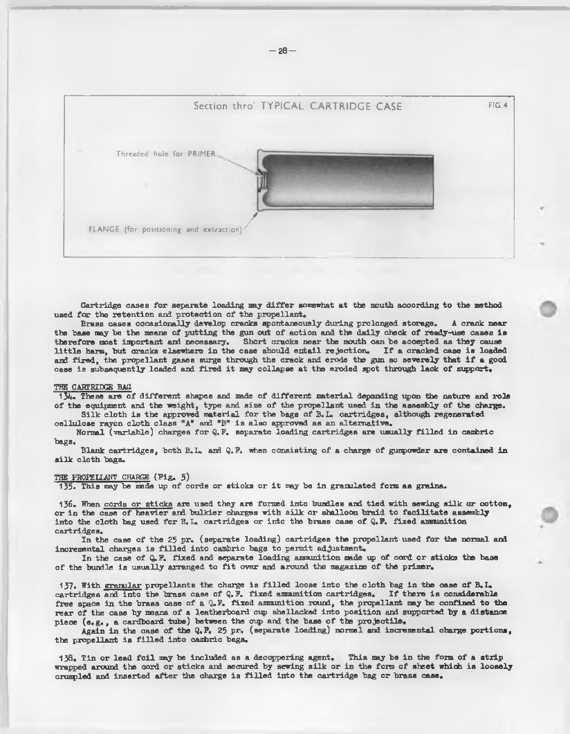
- 2 8 -
Section thro’ TYPICAL CARTRIDGE CASE F IG .4
Threaded hole for PRIMER
FLA N G E (for positioning and extraction)/
Cartridge cases fo r separate loading may d i f f e r somewhat a t the mouth according to the method used fo r the retention and protection o f the propellant*
Brass cases occasionally develop cracks spontaneously during prolonged storage. A crack near the base may be the means o f putting the gun out o f action and the d a ily check o f ready-use cases i s therefore most inport ant and necessary. Short cracks near the mouth can be accepted as they cause l i t t l e harm, but cracks elsewhere in the case should en ta il re jec tion . I f a cracked case i s loaded arkL fir e d , the propellant gases surge through the crack and erode the gun so severely that i f a good case is subsequently loaded and fire d i t may collapse a t the eroded spot through lack o f support<>
THE CARTRIDGE BAG134* These sire o f d iffe ren t shapes and made o f d iffe ren t material depending upon the nature and ro le
o f the equipment and the weight, type and size o f the propellant used in the assembly o f the charge.S ilk cloth is the approved material fo r the bags o f B. L» cartridges, although regenerated
ce llu lose rayon clo th class "A” and "B" i s also approved as sin a lternative .Normal (vsiriable) charges fo r Q.F. separate loading csirtridges are usually f i l l e d in cambric
bags.Blank cartridges, both B.L. and Q.F. when consisting o f a charge o f gunpowder are contained in
s ilk c lo th bags.
THE PROPELLANT CHARGE (F ig . 5)135. This may be made up o f cords or sticks or i t may be in granulated form as grains,
136. When cords or sticks are used they are formed into bundles and t ied w ith sewing s i lk or cotton, o r in the case o f heavier and bu lkier charges with s ilk or shalloon braid to fa c i l i t a t e assembly in to the cloth bag used fo r B. L. cartridges or into the brass case o f Q. F. fix ed ammunition cartridges.
In the case o f the 25 pr. (separate loading) cartridges the propellant used fo r the normal and incremental charges is f i l l e d in to cambric bags to permit adjustment.
In the case o f Q.F. fix ed and separate loading ammunition made up o f cord o r sticks the base o f the bundle is usually arranged to f i t over and around the magazine o f the primer.
137. With granular propellants the charge is f i l l e d loose in to the clo th bag in the case o f B.L. cartridges ard in to the brass case o f Q.F. fix ed ammunition cartridges. I f there i s considerable free space in the brass case o f a Q.F. fixed ammunition round, the propellant may be confined to the rear o f the case by means o f a leatherboard cup shellacked into position and supported by a distance piece ( e . g . , a cardboard tube) between the cup and the base o f the p ro je c t ile .
Again in the case o f the Q.F. 25 pr. (separate loading) normal and incremental charge portions, the propellant is f i l l e d in to cambric bags.
138. Tin or lead f o i l may be included as a decoppering agent. This may be in the form o f a s tr ip wrapped around the cord or sticks and secured by sewing s i lk or in the form o f sheet which i s loose ly crumpled and inserted a fte r the charge i s f i l l e d in to the cartridge bag or brass case.
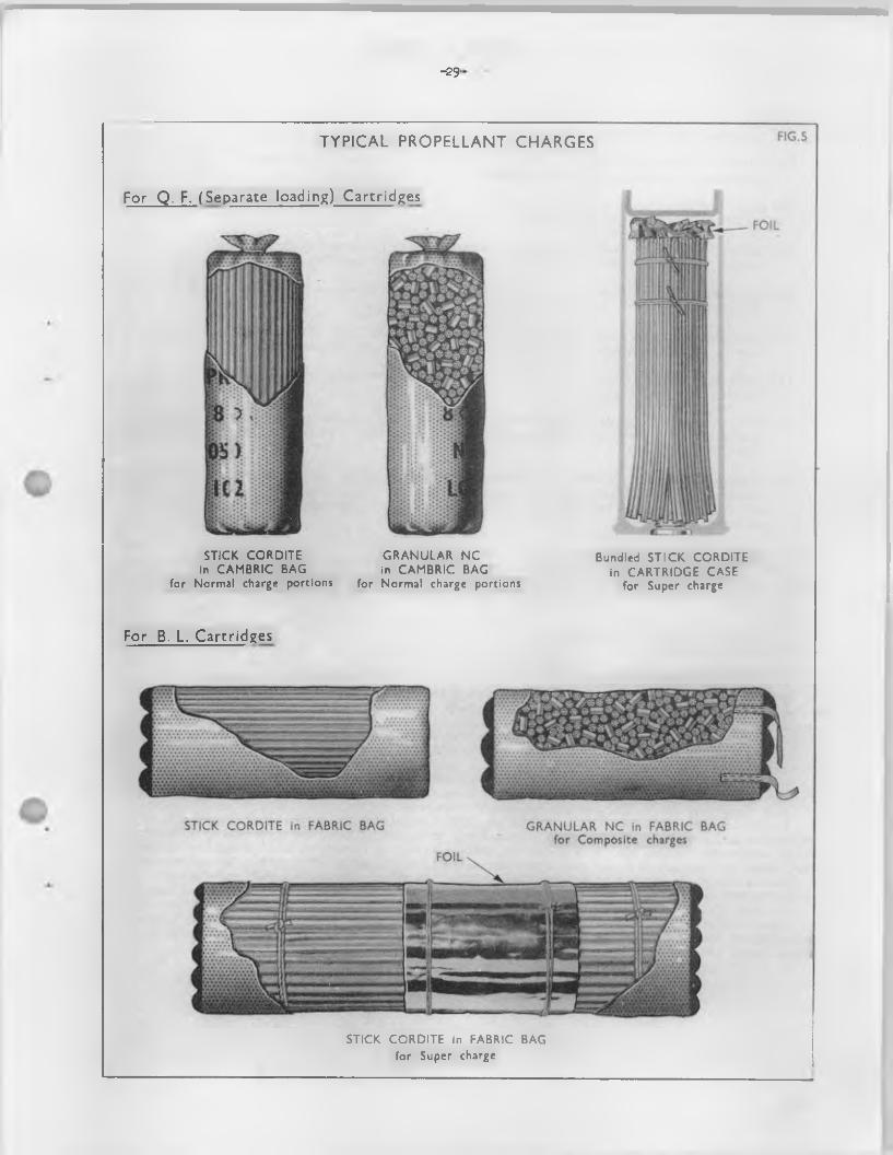
-29'
TYPICAL PROPELLANT CHARGES
For Q. F. (Separate loading) Cartridges
ST IC K C O R D IT E in CA M B R IC BAG
for Normal charge portions
G R A N U L A R N C in CA M B R IC BAG
for Normal charge portions
Bundled S T IC K C O R D IT E in C A R T R ID G E CA SE
for Super charge
For B. L. Cartridges
STICK C O R D IT E in FABRIC BAG for Super charge
- 5D-
CI lR(2 ^1fX± ES139. The fo llow ing type o f charge are used with F ie ld Branch A r t i l le r y Equipments: -
(a ) Service - The normal charge. I t does not usually give the maximum permissible b a l l is t ic performance obtainable with the equipment.
(b ) Super (form erly known as fu l l ) - The charge which gives maximum permissible regular b a ll is t ic s w ith the service weight o f p ro je c t ile .
(c ) Reduced - A charge which g ives lower pressures ard hence lower v e lo c it ie s than the normal Service charge. Wear is grea tly reduced. The charge i 3 often used fo r practice .
(d ) Fractional charge - With la rger B. L, equipments the Service charge i s sub-divided to fa c i l i t a t e transport, handling and loading.
(e ) Incremental charge - With howitzers and certa in separate Q. F. gun equipments the charge is made up in increments to permit variation o f the b a l l is t ic performance.
( f ) Paper shot charge - Used with paper shot to te s t the mounting or carriage when Service rounds cannot be fired .
(g ) Blank charge - A charge o f gunpowder or o f small sized propellant su ff ic ie n tly confined to g ive a report. Used fo r saluting and tra in ing purposes. I t must not be f ir e d w ith anyform o f p ro je c t ile .
(h ) Decqppering charge - T in fo i l or le a d fo il i s incorporated in the charge, when necessary, to counteract coppering o f the bore. Special decoppering charges, containing an extra amount o f f o i l may be used fo r cleaning a badly coppered gun, although such charges are not a normal Service issue.
140. Portions o f cartridge which are removed during the preparation o f the charge w i l l be set aside, e .g . in an empty cartridge box fo r eventual return to the R.A.O.C. fo r destruction or fo r use should the cartridges have to be made up to a higher charge. In making up cartridges by replacing portions which have been removed, care must be taken not to mix d iffe ren t natures o f propellant in the same cartridge.
PROPELLANT PROOF AND CHARGE ADJUSTMENT141. The object o f propellant proof and consequent charge adjustment i s to ensure that the
b a ll is t ic s obtained by the user from each charge that he f ir e s are as near constant as possible from round to round and from day to day.
A certa in " lo t " o f propellant is chosen and the b a ll is t ic s o f a given charge weight (known as the nominal charge weight) o f i t determined accurately; th is is known as the "master standard".Other lo ts o f the same propellant are then chosen and tested by f ir in g against th is master standard, and are known as "current standards". A l l other lo ts o f the same propellant are then tested against one o f these current standards; as a resu lt an a ltera tion is made to the charge weight o f any lo t to g ive the same b a ll is t ic s as the current standard. This process is ca lled "charge adjustment". I t w i l l be rea lized th erefore, that the weight shown in the designation and which is a lso marked on the cartridge is not necessarily the actual weight o f the charge used.
Each nature o f propellant has i t s own master standard.B a ll is t ic variations between cartridges o f d iffe ren t lo ts o f the same nature o f propellant that
have been so adjusted w i l l be very small unless the lo ts concerned have undergone w idely d iffe ren t storage conditions between the factory and the user. Nature to nature variations may however be la rge , since any two natures only give the same b a l l is t ic performances at a particu lar tenperature and a particu lar state o f wear o f a given gun. Since the relationships "weax/kV" and "charge tenperature/toT' are d iffe ren t fo r d iffe ren t natures o f propellant, i t is evident that mixed natures o f propellant w i l l not g ive good resu lts, and should never be used in p ractice , (but see para. 150).
Not a l l charges, however, are adjusted, e .g . , 25 pr„ charge 1 (W or W.M.). Such unadjusted charges should not be used fo r unobserved shooting; and lo ts should not be mixed since, with such charges, large lo t to lo t variations may occur.
- 3 1 -
Chapter 3
Cartridges
Section 2. Q.F. Cartridges
m E P ftT .
142. Cartridges are used in two ways, .forming -
Fixed annum.tion.Separate loading ammunition
143. With fixed ammun ition - The cartridge case is attached to the p ro je c t ile , by indenting or coning the mouth o f the case on to the rear end o f the p ro jec tile *
144* With separate loading ammunition - The p ro je c t ile is not attached to the cartridge case.
145. As a general ru le , fixed amnunition is used fo r a n ti-a ircra ft and tank and anti-tank guns; separate amnunition being used fo r howitzers and guiy'liowitzers.
For F ie ld Branch A r t i l le r y howitzers and gun/howitzers, cartridge cases are f it te d with a percussion primer screwed cen tra lly in to the base; th is generally contains a magazine having a su ffic ien t charge o f fin e grain gunpowder to dispense with the use o f an ign iter.
Fixed ammunition should not be used in guns or gui^/howitzers which are designed to f i r e separate loading amnunition. In an ordnance which has fir e d separate ammunition, the chamber is usually worn away at the point where the mouth o f the case i s situated, and i f a fix ed round be then fire d , the fron t end o f the case w i l l expand into th is worn portion and w i l l be lia b le , therefore, to cause a jam. Secondly, in separate loading ammunition, the p ro je c t ile must never be inserted in the cartridge case and the two loaded as an en tity , as, i f th is is done, the driving band w i l l not correctly engage in the r i f l in g and, on f ir in g , propellant gases may be forced over and in fron t o f the driving band and cause e rra tic ranging or even a premature. Thus with separate loading amnunition, the p ro je c t ile must be co rrectly rammed horns before the cartridge is loaded.
SUB-DIVISION OF CARTRIDGES14^. For fixed ammunition, cartridges may be sub-divided in to 8 categories i . e . , normal, super
v e lo c ity , super, high v e lo c ity , reduced, c learing, paper shot and blank. Such charges cannot be varied, and can only be used fo r the sp ec ific purpose fo r which they are introduced*
For separate loading guns and gurv/howitzers, cartridges are usually sub-divided in to normal (which are variable) and super, paper shot and blank which are not variab le. Incremental charges fo r use in conjunction w ith the variable sections o f the normal charge arid in certa in instances with super charges may also be supplied.
DESIGN OF CARTRIDGES147* Fixed ammunition charges are normally cy lind rica l in shape.
In nearly a l l cases the propellant used is cord ite in the form o f sticks* The sticks are formed into bundles t ied with sewing s i lk and are then inserted in the cartridge case. I f granulated powders 3uch as NH or TNH are used these are usually f i l l e d loose in to the case.
Separate loading ammunition charges, other than the normal charge, are sim ilarly made up, but in such instances the mouth o f the case is closed by a leatherboar d 0151, to prevent the charge being ejected on loading and handling.
148. Q.F. 25 pr. (separate loading) cartridges- Normal charge sections and incremental charges are contained in cambric bags, the material being dyed d iffe ren t colours to fa c i l i ta te ready id en tific a tion o f the 1st, 2nd and 3rd portions. The mouth o f the case is closed by a leather-board cup which has a l i f t in g becket to fa c i l i t a t e removal fo r adjustment o f the charge.
Super charges are not adjustable, and are consequently inserted (t ie d w ith s ilk sewing but not enclosed in a bag) loose in the cartridge case. For th is reason the mouth o f the cartridge case is closed by a leatherboard cup which has no l i f t in g becket and which is secured by shellac.
- 3 2 -
Chapter 3
Cartridges
Section 3. Types of Q.F. (Separate loading) Cartridges used in Field Branch Artillery Equipments
Q.F. 25 H4 GUN149. In t il ls instance the term "cartridge" is applied to the brass cartridge case assembled with the
percussion primer, propellant charge and retaining cup.
NORMAL CHARGES (F ig . 6)150. The normal charge consists o f three portions, each contained in a coloured cambric bag:-
1 st portion (red bag) 1 st charge ) }2nd portion (white bag) ) 2nd charge )3rd portion (blue bag) ) 3rd charge
The corrplete charge is usually composite, i . e . , made up w ith two sizes o f propellant which may be o f d iffe ren t natures,, The propellant may be e ith e r cordite or NC powder:-
(a ) Cordite charges (typ ica l)The smaller diameter co rd ite , in sticks o f two lengths, is used in the 1st (red ) portion, the longer sticks being t ie d round the shorter ones to form a recess to accomnodate the primer. A ltern a tive ly sticks o f one length may be used to form a ring-shaped charge sim ilar to that fo r NC powders.The la rger diameter cordite i s f i l l e d loose in to the 2nd (w hite) and 3rd (b lue) bags.F o il, when used, is placed in the blue bag which is a lso f i t t e d with a l i f t in g becket.
(b ) NC chargesThe smaller s ize grains are used in the 1st (red ) portion which i s shaped in the form o f aring e ith e r by pu lling the mouth o f the bag over the closed end and sewing together withs ilk , or by closing the mouth by sewing and stitch ing i t to the other end o f the charge.To fa c i l i t a t e assembly, the ends, w i l l , in future, be l e f t free .The la rger s ize grains are f i l l e d in to the 2nd (w h ite) and 3rd (b lue) bags, f o i l , when used, being placed in the la tte r .Charges were formerly held in the case by two paper strips diam etrically opposed, secured to the case with shellac, the ends being turned over end shellacked together. In current production, security o f the charges is achieved by the use o f t ig h t ly f i t t in g closing cups.
(c ) NQ chargesTwo types have been approved. The e a r lie r type made up as described in (a ) above and a la t te r type where a l l three portions, although f i l l e d to d iffe ren t weigjits, are assenbled with the propellant cut to the same length (see F ig . 6),
151 • The mouth o f the case is closed by a leatberbo&rd cup (two cups were used in some ea r ly production cartridges) which has a l i f t in g becket to fa c i l i t a t e removal fo r adjustment o f the charge®
SUPER CHARGES (F ig . 6)152. The super charge may be f i l l e d to d iffe ren t charge types, each type consisting o f a bundle o f
cord ite sticks o f one size only, t ied with sewing s i lk but not enclosed in a bag. Charges o f ea r ly manufacture contained sticks o f two lengths, tbs longer sticks being t ied around the shorter ones to form a recess fo r the primer.
Tin or lead f o i l , loosely crunpled, i s placed on top o f the charge or wrapped around the charge. Super charges are not adjustable. For th is reason the mouth o f the cartridge case is closed
by a leatherboard cup which has no l i f t in g becket and is secured with shellac.
NOTE:- For f ir in g the 20 lb . A.P„ shot the weight o f the super charge i s increased by a super charge incrensnt which is placed in the mouth o f the cartridge closing cup.
153. A l l normal and super charges are based on method o f f i l l i n g design DD(L)11242 but there are a number o f marks o f cartridge within the M. o f F. and the arrangement o f propellant (and sometimes components) may ’/ary considerably within each marie. Variations in arrangement are known as charge types and are deta iled in Appendix E. Part 1. para. 3 and Section 2 Table 2 R.A.O.S. Volume 4 - Ammunition, Pamphlet No. 7 Part 20
-33-
TYPICAL EXAMPLES-SEPARATE LOADING CARTRIDGES - Q F. 25 PR.
N O R M A L (VA RIABLE) C H A R G ES
BAGS FILLED C O R D IT E OR G R A N U L A T E D N £ P O W D ER
BLUE BAG PO RTIO N
RED BAG PO RTIO N
BLUE BAG PO RTIO N
PRIMER screwed into CASE
W H IT E BAG PO R TIO N
CASE;
RED BAG PO R TIO N
W H IT E BAG PO R TIO N
SUPER C H A R G E
LE A TH ER B O A R D C L O S IN G CU P
FOILD ECO PP ER IN G A G E N T
PRO PELLAN T(Cord Cordite)
PRIMER screwed into C A R T R ID G E CASE
IN CR EM EN T C H A R G E S
For NORMAL (VARIABLE) CHARGES
- 3 4 “
INCREMENT CHARGES (P ig . 6)154. Intermediate charge increment - The charge, which is contained in a white cy lind rica l cambric
bag, choked at the mouth with sewing s i lk and marked a x ia lly with red stripes 5/8 inch wide at5/8 inch in terva ls , is fo r use with charge 1 or 2 only.
155. Super charge increment - This charge was introduced to supplement the super charge when f ir in g 20 lb . A.P. shot and may not be used with any other p ro je c t ile . Two types have been introduced v iz .
5.1/2 oz. NQ/S 134-0^0 in ce llu lo id container4. 1/2 oz. chopped ( 0.25 inch) WM 061 in ce llu lo id container.
Only a few lo ts o f 5«'l/2 oz. NQ/S increment have been produced, since the brittleness o f the propellant makes sa tisfactory cutting inpossible. For th is reason and because a fla shi ng propellant such as WM is more suitable fo r the anti-tank ro le , the 4.1/2 oz. WM 061 increment has taken i t s place.
ISSUE AND PREPARATION15^. The charges are issued and prepared fo r fir in g as fo llow s :-
(a ) Charges 1 , 2 and 3 - These charges are issued together in the cartridge case, the conplete unit forming charge 3» To prepare charge 2, the blue portion must be removed, leaving the red and white portions. To prepare charge 1, the blue and white portions must be removed, leaving the red portion only. The portions o f cartridges which have been removed cannot be used to make up other charges i . e . the white and blue portions together w i l l not make charge 2 nor w i l l the red and blue.
(b ) Charge super - This charge is issued as a separate conplete unit in a cartridge case.I t requires no preparation neither can i t be broken down to form charges 1, 2 or 3.
(c ) Charge super plus increment - This charge is made by the addition o f a super charge increment which i s placed in the mouth o f the cartridge case closing cup. This charge may only be used when f ir in g 20 lb . A.P. shot*
(d ) Intermediate charges - These are provided to enable a high tra jec to ry to be used at a l l ranges, the high tra jec to ry being required:-
( i ) To c lea r crests.
( i i ) To g ive a large variety o f angles o f a rr iv a l, and hence angles o f inpact, so that the best use may be made o f sh e ll and fuzes.
In mountainous country the number o f charges normally issued may not be su ffic ien t to enable a l l the ground w ithin the range o f the gun to be covered. I t may be impossible to h it a given target with a certain charge because the sh e ll cannot be dropped in behind the crest, due to the shape o f the tra jec to ry given by that charge; the next lower charge may not have the required range to reach the target. Intermediate charges are, th erefore, provided fo r sons equipments; in the case o f the Q.P. 25 pr. gun they a re :-
F irs t charge
Second charge
Second charge
+ 1 intermediate increment
+ 1 intermediate increment
+ ” 2 intwemediate increments
- 3 5 -
Chapter 3
Cartridges
Section 4. B.L. Cartridges
GENERAL157. B.L, cartridges are normally o f cy lin d rica l shape.
In nearly a l l cases the propellant used is cord ite in the form o f sticks. The sticks are formed into bundles t ied with sewing s ilk , or, in the case o f heavier cartridges, with s ilk braid, in order to secure r ig id i t y o f shape and fa c i l i t a t e insertion in to the bag, and subsequent loading into the chamber o f the ordnance. In those cartridges f i l l e d with granulated powders such as N,KH or FNH, the propellant is f i l l e d loose.
The charge is inserted into a bag. The open end is then closed by the ig n ite r being sewn on to i t . Where two ign iters are used the second ig n ite r i s sewn to the bottom end o f the bag before insertion o f the charge*
L ift in g beckets o f braid are f i t t e d to the la rger cartridges to assis t handling operations.
SUB-DIVISION OF CARTRIDGES158* For howitzers and gun hovdtzers, cartridges are necessarily sub-divided in to part charges,
v i z . , 1 st (low est), 2nd, 3rd, etc.For guns, sub-division i s only resorted to fo r two purposes:-
(a ) Excessive weight and s ize o f the fu l l charge in the la rger natures.
(b ) The use o f a fu l l and reduced charge in one gun, as, fo r example, when h a lf or two-thirds charges may be required fo r practice or other purposes, and i t is found most convenient to make the fu l l charge up from two separate charges in the required proportion. These are t ied firm ly together with the ends butted by means o f fa ir leads and lashings.
MATERIALS159. The requ isite qu a lities o f material fo r c lo th cartridge bags are: -
'(a ) I t mast be strong enough to withstand the wear and tea r o f transport and handling.
(b ) I t should not deteriorate in store or be a ffected by the chemicals in the propellant.
(c ) I t mast be en tire ly consumed when the gun is fir e d and mast leave no smouldering pa rtic les or other residue.Accidents have occmred from th is cause, generally when using blank cartridges or reduced charges, fo r which special precautions are la id down and should be ca re fu lly adhered to (see para. 311).
160. The material fo r ign ite rs (see paras. 185 to 189) must, in addition to possessing the above qua lities -
(a ) be so close in texture that the gunpowder cannot come out
(b ) be permeable to the flash from the tube.
Generally speaking, s ilk c lo th fu l f i l s the conditions fo r cartridge bags and shalloon fo r ign iters.
In the past, cream serge, shalloon and cloth mixtures "A", WB" and "Z” have been used as a lternatives to s ilk -c lo th but the use o f these, except in an emergency, i s no longer permitted. Regenerated cellu lose rayon cloth class MA" and WB" is , however, approved as an alternative to s ilk cloth.
DIAMETER AND IENGTH161. Diameter - The cartridge should be large enough to ensure that some part o f the gunpowder in
the ign ite r w i l l encounter the flash from the tube.
162. Length - The cartridge should be long enough to ensure that, under a l l conditions, the ig n ite r w i l l be close to the mushroom head o f the breech mechanism o r at least the distance between the tube and ign ite r is not excessive.
In order to obtain the best possible regu la rity in b a l l is t ic s , i t i s essen tia l that the length o f the cartridge should, i f possib le, approximate to the fu l l length o f the chamber.
- 3 6 -
DESIGN OF B. L. HOWITZER AND GUN/HOWITZER CARTRIDGES 1 63. Considerations governing design - Cartridges fo r B. L. howitzers and gun/howitzers are made 15)
o f the same m aterials, "but in a manner en tire ly d iffe ren t from that employed fo r B. L. gun cartridges, fo r the fo llow ing reasons
(a ) The ordnance is intended fo r high-angle f i r e , hence the charge is mach lig h te r compared with that o f a gun o f the same ca lib re .
(b ) I t is a comparatively short p iece o f ordnance, therefore the charge must be quick-burning (small s ize o f coni or tubular cord ite ) so that the whole o f the charge may be consumed before the p ro je c t ile leaves the muzzle,
(c ) With such equipments, large angles o f descent may be required at short as w ell as long ranges. These are obtained by a lte rin g the weight o f the charge; therefore, a cartridge fo r a howitzer is made up in sections in such a manner that i t s weight can be read ily reduced.
164. Princip les o f design - The main princip les in design a re :-
(a ) The lowest charge must be stable, i . e . , does not tend to f a l l over or lose i t s shape when loaded alone and so cause a m isfire or delay in complete ign ition .
(b ) The ig n ite r , which i s always f i t t e d over the base o f the lowest charge, is made o f the largest possible diameter; th is is to ensure not only that the fla sh impinges d ire c t ly on to the gunpowder but also that the ign ite r as nearly as possible covers the whole o f the cartridge and causes good and regu lar ign ition o f the charge.For th is reason the diameter o f the rear end o f the charge is not less than the maximum diameter o f the complete cartridge, whenever possible.In most o f the cartridges a mushroom-shaped lowest charge is therefore used.A number o f cartridges have also been introduced in which, while the mushroom-shaped core is retained, the auxiliary or incremental sections are formed not as rings as formerly, but as f la t segments which are p lia b le enough to be f i t t e d and secured around the stalk.In other designs the 1st charge and incremental sections are formed cy lin d r ica l, the portions being butted together and secured by webbing t ie s .
165. The substitution o f segments fo r rings - I s rendered necessary by reason o f the la rger sizes o f propellant used in the cartridges, as i t is a matter o f some d i f f ic u lt y to bend bundles containing these la rger sizes o f propellant into a formation o f rings. I t is also desirable because in the segments the lengths o f the sticks are arranged p a ra lle l to the core, the in ters tices forming a number o f p a ra lle l passages proceeding from the ig n ite r ; the whole surface o f the charge i s , therefo re , in the most favourable position to receive the in it ia t in g flash.
With the introduction o f h igh -veloc ity howitzers and gur/howitzers with long but narrow chambers, a very long sta lk i s en^loyed which is much longer than is necessary fo r the s ta b il ity o f the lowest charge used. The reason fo r th is is , that i t has been found that the f ir in g o f-a small charge, seated at the end o f a long chamber, is lia b le to cause excessive pressures due to "wave action ", so with guns and howitzers having long chambers, where small charges are used, the charge is arranged to stretch the whole length o f the chamber, or as nearly so as possible.
The long sta lk is very convenient fo r accommodating the desired number o f auxilia ry or incremental sections, which can be conveniently arranged around i t in one or more t ie r s .
ARRANGEMENT OF HOWITZER AND GUN/HOffITZER CAKTKTDfflS166. Each section o f the cartridge is marked w ith a number to be used when the d iffe ren t charges
are being prepared fo r f ir in g .The core or main section , which carries the ig n ite r , is always marked No. 1 (o r one): the
auxiliary sections, Nos. 2, 3, 4 (o r two, three, four) and so on.D ifferent charges are obtained by removing one o r more o f the auxilia ry sections. Thus, in
the case o f a cartridge conprising a core (No. 1 section) and three subsidiary sections (Nos. 2,3 and 4 sections ), the charges made up from th is a re :-
Fourth charge Nos. 1, 2, 3 and 4 sections Third charge Nos. 1 , 2 and 3 sectionsSecond charge Nos. 1 and 2 sections F irst charge No. 1 section.The weights o f the sections are selected in such a manner as to provide fo r a l l ranges.
Charges made up from other combinations are therefore unnecessary.Adequate overlap in the range is provided between consecutive charges. This suggests that,
at the point o f overlap, the lowest charge should, where possib le, be selected, in order to conserve the l i f e o f the howitzer; i t a lso has the advantage o f g iving a la rger angle o f descent.
In certain equipments the " fu l l " charge cartridge is f i l l e d and issued as a conplete cy lin d rica l cartridge i . e . i t is not adjustable.
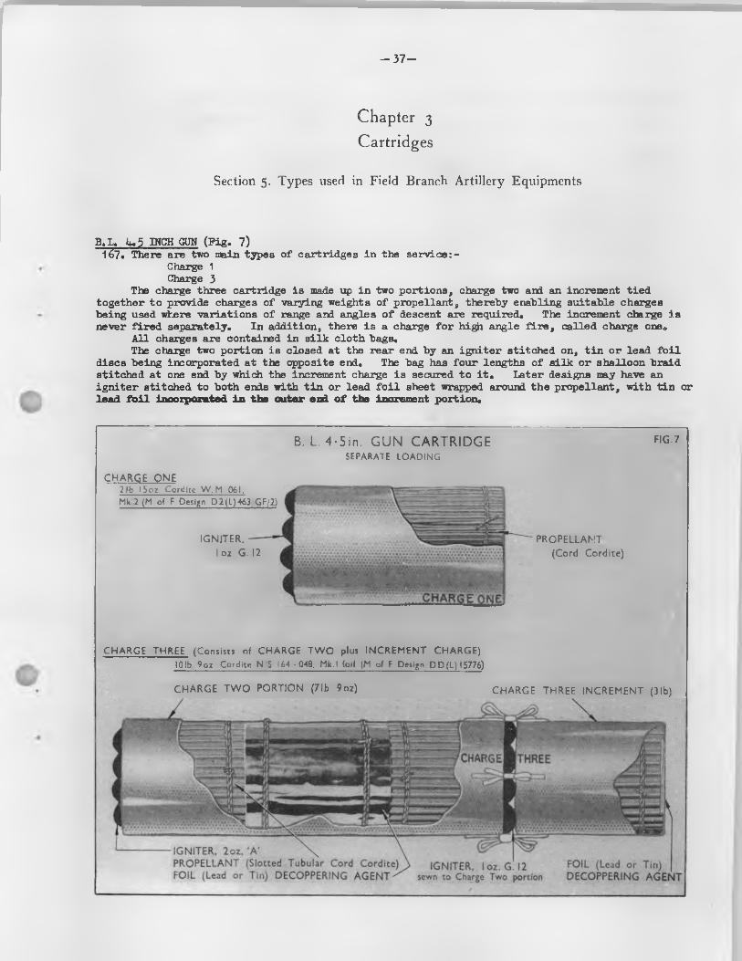
-37-
Chapter 3
Cartridges
Section 5. Types used in Field Branch Artillery Equipments
B.L, lu 5 INCH GUN (F ig . 7)167* There are two main types o f cartridges in the service: -
Charge 1 Charge 3
The charge three cartridge is made up in two portions, charge two and an increment tied together to provide charges o f varying weights o f propellant, thereby enabling suitable charges being used where variations o f range and angles o f descent are required* The increment charge is never fir e d separately. In addition, there is a charge fo r high angle f i r e , ca lled charge one*
A ll charges are contained in s ilk c lo th bags.The charge two portion is closed at the rear end by an ig n ite r stitched on, t in or lead f o i l
discs being incorporated at the opposite end. The bag has four lengths o f s ilk o r shalloon braid stitched at one end by which the increment charge is secured to i t . Later designs may have an ig n ite r stitched to both ends with t in or lead f o i l sheet wrapped around the propellant, with t in or lead f o i l incorporated in the outer end o f the increment portion.
CHARGE, THREE
C H A R G E T W O PO R TIO N (7 lb 9oz) C H A R G E TH R EE IN C R EM EN T (3 lb)
IG N ITER , 2oz, ‘A'PR O PELLA N T (Slotted Tubular Cord Cordite) \ IG N ITER , lo z . G I2 FOIL (Lead or Tin) D ECO PP ER IN G A G E N T ' sewn to Charge Two portion
FOIL (Lead or Tin) D ECO PP ER IN G AGENT
B. L. 4• 5 in. GUN CARTRIDGE ^ .7SEPARATE LOADING
C H A R G E O N E2 lb !5oz. Cordite W.M. 06I,Mk.2 (M of F Design D2(L)463.’GF/2)
IG N ITER , lo z . G. I2
PR O PELLA N T (Cord Cordite)
C H A R G E THREE (Consists of C H A R G E T W O plus IN C R EM EN T CH A R G E)lOlb. 9oz. Cordite N'S I64 -048, Mk.l foil (M of F Design DD(L)I5776)
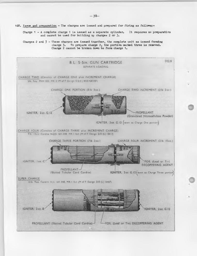
- 3 8 -
168. Issue and preparation - The charges are issued and prepared fo r f ir in g as fo llows
Charge 1 - A complete charge 1 is issued as a separate cylinder* I t requires no preparation and cannot be used fo r building up charges 2 or 3*
Charges 2 and 3 - These charges are issued together, the complete unit as issued forming charge 3» To prepare charge 2, the portion narked three is removed.Charge 2 cannot be broken down to form charge 1*
B.L. 5■ 5in. GUN CARTRIDGE! SEPARATE LOADINGii
C H A R G E T W O (Consists of C H A R G E O N E plus IN C R EM EN T C H A R G E )5lb. 5oz. FNH 023, MK.2 (M of F Design D 2 (L) 403S/GF I87)
C H A R G E O N E PO R T IO N (3 lb 3oz.) C H A R G E T W O IN C R EM EN T (2lb 2oz.)
IG N ITER , 2oz. G . I2 ^sewn to Charge One portion
C H A R G E FO U R (Consists of C H A R G E TH R EE plus IN C R EM EN T CH A R G E)9 lb. 13 oz. Cordite NQ $ 164-048. MKT foil (M of F Design D D (L) I06I2)
IG N ITER , lo z . C
T H R E E PO R TIO N (7lb 3oz.) C H A R G E FO U R IN C R EM EN T (2lb lOoz.)
PRO PELLAN T (Slotted Tubular Cord Cordite)
FOIL (Lead or Tin) D EC O P P E R IN G A G E N T
2oz. G .I2fsew n to Charge Three portion]
SUPER C H A R G E12 lb. 9oz. Cordite N/S I64-048, MKT foil (M of F Design D D (L) 16407)
- 39-
B.L. 5.5 INCH GUN (P ig . 8)1^9* There are four main types o f cartridges in the Service, these being: -
Charge 2 (short range portion)Charge 4 (long range portion)Super charge ( fo r use with 80 lb. shell only)Paper shot
The cartridges in th is instance also are enclosed in s ilk c lo th bags to which a gunpowder ig n ite r is stitched to the end which is loaded nearest the tube.
In order that variable charges may be used, they are made up in d iffe ren t weights o f propellant* Charge three and an increment charge t ied together form charge four. Tin or lead f o i l discs are incorporated with the increment charge, which is never f ir e d separately.
There is also a super charge marked " fo r 80 lb . shell only", th is is also id en tified by a 1 inch wide black band placed 7 inches from the end o f the charge.
170. Issue and preparation - The charges are issued and prepared fo r f i r in g as fo llow s :-
Charges 1 and 2 - These charges are issued together, the complete unit, as issued forming charge 2.To prepare charge 1, the portion marked TWO is removed. These charges cannot be used fo r building up charges 3 o r 4*
Charges 3 and 4 - These charges are issued together, the couplete unit as issued forming charge 4. To prepare charge 3, the portion marked POUR is removed.Charge 3 cannot be broken down to form charges 1 or 2*
Super Charge - This charge is issued as a separate conplete unit. I t requires no preparation and cannot be broken down to form charges 3 o r 4
33. L. 7.2 INCH HOWITZER (P ig . 9)171. There are three main types o f cartridges in the Service, these being:-
Charge 3Charge 4Charge 5 increment.
The charge 3 cartridge is made up in portions to provide charges o f various weights o f propellants, thereby enabling suitable charges being used where steep angles o f descent and variations in range are required. Each portion is enclosed in a s ilk -c lo th bag, the No. 1 portion has a head ard core while Nos. 2 and 3 portions are o f d iffe ren t weights and are shaped to f i t around the core o f the No. 1 portion.
No, 1 portion is always fired . I t may be augmented by portions Nos. 2 and 3, the three portions making a fu l l charge. An ig n ite r is a ffix ed to the base o f portion No. 1 and two tapes, 1 inch wide, are stitched diam etrically opposite each other to the sides o f the bag to secure Nos. 2 and 3 portions.
No. 2 and 3 portions vary in depth according to the quantity o f propellant in each. They Eire secured and t ied t ig h t ly around the core by webbing braid sewn to the clo th and the ends t ied in a bow. Two 1 inch tape fa irleads are sewn to the cloth o f each portion fo r the tapes o f No. 1 portion to pass through, the la t te r being secured by a bow t ie on top o f the No. 3 portion.
Other designs o f charge 3 cartridges d i f f e r from the above in that the three portions are a l l made up cy lin d rica l in shape, d if fe r in g mainly in depth according to the quantity o f propellant in each. The three portions are secured end to end by webbing t ie s .
The charge 4 cartridge is issued as a conplete unit. The propellant is contained in a cy lin d rica l s ilk -c lo th bag. Cartridges f i l l e d FNH have a gunpowder ig n ite r attached to the base o f the bag, while the mouth o f the bag is choked with s ilk thread. Cartridges f i l l e d N/S have an ign ite r a ffix ed at each end.
A charge 5 increment, which lias an ig n ite r a ffix ed a t each end, is provided to form a supercharge fo r use with charge 4 in mark 6 howrs. only.
172. Issue and preparation - The charges are issued and prepared fo r f ir in g as fo llow s:-
Charges 1 ,2 and 3 - (WM, N or ENH propellant) - The charges are issued together, the conplete unit as issued forming charge 3. To prepare charge 2 the portion marked "3" is removed. To prepare charge 1 the portions marked "2" and "3" Eire removed.
Charge 4 (ENH or N/S propellant) - This charge i s issued as a separate unit. I t requires no preparation and cannot be broken down.
Charge 5 - This charge i s obtained by guiding a charge 5 increment to the charge 4 unit.Care should be taken, where possib le, to ensure that the charge 5 increment and the charge 4 unit are o f the same propellant nature.
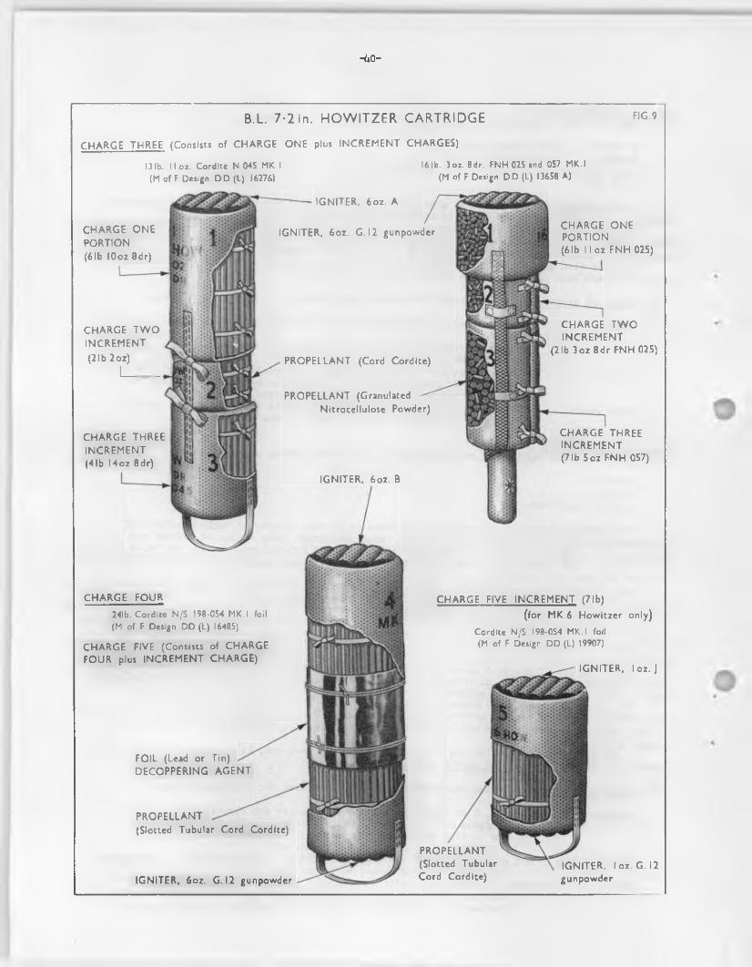
-ko-
B.L. 7-2 in. HOW ITZER CARTRIDGE F|G-9
C H A R G E TH R EE (Consists of C H A R G E O N E plus IN C R EM EN T CH A R G ES)
13 lb. ! I oz. Cordite N 045 MK.I 16 lb. 3oz. 8dr. FNH 02S and 057 MK.I(M of F Design D D (L) 16276) (M of F Design D D (L) 13658 A)
C H A R G E O N E PO RTIO N (61b lOoz 8dr)
FOIL (Lead or Tin) D EC O P P ER IN G A G E N T
IG N ITER . 6oz. A
IG N ITER , 6oz. G . I2 gunpowderC H A R G E O N EPO RTIO N(61b l l o z FN H 025)
PR O P ELLA N T (Slotted Tubular Cord Cordite)
IG N ITER , 6oz. G . I2 gunpowder
PR O PELLA N T(Slotted Tubular Cord Cordite)
PR O PELLA N T (GranulatedNitrocellulose Powder)
IG N ITER , lo z . G . 12 gunpowder
C H A R G E T W O IN C R EM EN T
(21b 2oz)
I_______
C H A R G E TH REE IN C R EM EN T (71b 5oz FN H 057)
C H A R G E FOUR
24!b. Cordite N/S 158-054 MK.I foil (M of F Design DD (L) 16485)
C H A R G E FIVE (Consists of C H A R G E FO U R plus IN C R EM EN T C H A R G E )
C H A R G E FIVE IN CR EM EN T (71b)
(for MK.6 How itzer only)
Cordite N/S 198-054 MK.I foil (M of F Design DD (L) 19907)
IG N ITER , lo z . J
PR O P ELLA N T (Cord Cordite)
C H A R G E T W O IN C R EM EN T
(21b 3oz 8dr FN H 025)
C H A R G E TH R EE IN C R EM EN T (41b l4 o z 8dr)
IG N ITER . 6oz. B
-41-
Chapter 4
Means of Ignition
Section 1. Introduction
IGNITION OF THE PROPELLANT CHARGE173* The propellant charge i s ign ited by the f ir in g o f an igniferous in it ia to r , i . e . , by the impact
o f a s tr ik er on to a percussion cap assembled in the base o f the primer o r tube* The small fla sh given by the in it ia to r i .e * the percussion cap is picked up and amplified by a gunpowder charge contained in the magazine portion o f the primer or tube. This charge is normally su ffic ien t to ensure that the spaoe in the chamber o f the gun surrounding the propellant charge is rap id ly f i l l e d with gases o f su ffic ien t temperature and heat content to ensure even and rapid ign ition o f the propellant over the whole o f i t s surface.
Only with uniform ign it ion w i l l regu larity o f b a ll is t ic s be achieved.The amount o f gunpowder used in the primer o r tube depends upon the chamber dimensions o f the
gun, the s ize o f the propellant charge and the ease with which i t i s ign ited i . e . , upon the nature o f the propellant.
174. Q.F. cartridges - As the fla sh from the primer is not su ff ic ie n tly powerful to ign ite the charge with certa in ty and regu larity , certa in charges, depending upon the nature o f the propellant, are assembled with a supplementary ign ite r which i s positioned in the base o f the charge so that i t is in d irect contact and augments the gunpowder charge in the magazine o f the primer.
175. B.L. cartridges • As the fla sh from the tube is not su ff ic ie n tly powerful to ign ite modern propellants w ith certa in ty, smoothness and regu larity , a charge o f gunpowder enclosed in a shalloon bag termed an ig n ite r , i s attached to the base or breech end o f a l l B.L. cartridges. Ih is ig n ite r i s o f the largest possible diameter and is designed and positioned so that some part o f the gunpowder w i l l encounter the flash from the tube and thus ensure good and uniform ign it ion o f the whole o f the propellant charge. To achieve th is requirement the distance between the tube and ig n ite r must not be excessive.
Chapter 4
Means of Ignition
Section 2. Primers
GENERAL176. Primers are the means employed fo r in it ia t in g the propellant charge in most modern Q.F.
equipments.The ign iferous in it ia to r in the cap and the gunpowder in the magazine o f primers, i f allowed
to become a ffec ted by dan?), w i l l cause m isfires and hangfires.With some primers and propellants an ig n ite r is used to rein force the fla sh from the primer
and ensure e f f ic ie n t ign ition .Primers can be repaired and used again.Primers should invariably be removed from the cartridge case should i t ever be necessary to
use force to get the case in to the breech o f the gun. This pa rticu la rly applies to any form o f hammering, as not only might the primer cap be struck by accident but the shock might w e ll damage i t . The primer can be replaced once the case is fu l ly home.
PERCUSSION - DESCRIPTION (F ig.10 )177* The percussion primer contains three main elements; the cap, gas check and magazine.
178« Cap - This consists o f a small copper shell containing about 1 grain o f cap composition, covered with a t in f o i l disc and assembled with a f i l l e t o f waterproofing composition in the primer, with the open end close to an anvil and nearest to the magazine. E ither D.C.A. or Q.F. composition may be used. D.C.A. i s somewhat more sensitive and provides more certa in ty in action, but experience has shown that i f primers containing th is composition are rammed home by a power rammer and subsequently unloaded there Is a serious risk that they w i l l function prematurely when next rammed into the gun. In fa c t , a primer containing D.C.A. must not be power rammed a second time, but should be removed when the round is unloaded and replaced by a new primer. Primers containing

-2*2 _
D.C.A. ("A " composition) are not sp ec ific a lly marked, but a l l primers containing Q.F. composition subsequent to the end o f 1939> have the le t t e r nQ" s ta ge d an the base. Sane o f the packages containing cartridges f i t t e d with these primes®had the le t t e r wQn sten c illed on the ends, but th is has since been discontinued.
The cap composition is in it ia ted by the cap being driven down onto the anvil by the s tr ik e r o f the f ir in g mechanism.
179. Gas check - The obturation or prevention o f gas escape through or past the primer i s o f great importance as gas wash may cause serious damage to the breech mechanism.
Rearward escape o f gas through the primer i s prevented by a copper b a ll or cone which is contained in a central recess in the anvil and retained by a plug. This recess i s connected by f i r e holes in the an v il to the cap and by f i r e holes in the plug to the magazine. This arrangement permits the fla sh from the cap to pass to the magazine, but the b a l l or cone is forced back on to a seating by the explosion o f the primer magazine and thus seals the f i r e holes in the anvil.
180. Magazine - The compartment housing the gunpowder is designated the magazine and may be formed as an in tegra l part o f the body or i t may be a separate component screwed on to the primer body. I t s length may vary within wide lim its in d iffe ren t descriptions o f primers. I t contains gunpowder, usually G.12.
In tegra l magazines have a closing disc securely fix ed to the body but weakened to provide an easy opening without fracturing, as debris in the bore might be troublesome.
The separate magazine is provided with f i r e holes, and a lin e r prevents escape o f the powder, the lin e r being also varnished with shellac varnish as a protection against damp. Some o f these magazines have a f i r e hole a t the forward end and to prevent accidental perforation o f the lin e r by the propellant, th is hole i s covered by a white metal Mdane", the white metal o f which a lso acts as a decoppering agent.
FIG. 10
TYPICAL PERCUSSION PRIMER
Exterior viewCO PPER BALL PLU G (with 3 radial and I central fire holes)
PAPER DISC M A G A ZIN E G U N P O W D E R
Action of gas - check upon firingA N V ILCAP
CO PPER BALL
ACTION (P ig . 10)181. The s tr ik er o f the f ir in g mechanism is driven on to the cap (o r cap holder) and the composition
i 3 nipped on the an vil. The flame passes through the f i r e holes in anvil and plug, past the h a ll or cone and ign ites the gunpowder in the magazine. The resultant explosion forces the h a ll or cone hack on to i t s seating preventing in ternal gas escape to the rear, and tra v e llin g forwards through the closing disc or f i r e holes ign ites the propellant charge.
GENERAL182. Tubes are vised in B.L, guns and howitzers to in it ia te the propellant charge. The tube i s
assembled in the ax ia l vent and on being fired produces a fla sh to ign ite the clo th ig n ite r attached to the base o f the propellant charge. The flash should be a3 strong and regu lar as possible to ensure rapid and certa in ign ition o f the cartridge ign ite r . As the distance between the rear end o f the cartridge and the front end o f the vent varies with the type o f gun and the charge in use, the strength o f the fla sh must be su ffic ien t fo r the maximum distance that may be met. The gas sealing action o f the tube in the vent is sim ilar to that o f a Q.P. cartridge in a gun chamber.
PERCUSSION. S.A. CARTRIDGE (F ig . 11)183. The tube consists o f a case, a cup above which is an anvil and gas seal w ith copper b a ll. The
forward part o f the case being the magazine which is f i l l e d with gunpowder, the mouth being close'* by a cork plug.
ACTION184. When the percussion mechanism is operated, the cap is 3tm ck by the point o f the f i r in g pin,
so that the detonating conposition is pinched between the anvil and the in te r io r base o f the cap, and thus fired . The resulting fla sh passes through the three holes in the plug to ign ite the powder in the magazine which, in turn, ign ites the clo th ig n ite r attached to the base o f the propellant charge. The so ft copper b a ll is driven to the rear by the explosion in the magazine and the w a ll o f the case is expanded ra d ia lly so preventing escape o f gas to the rear from the tube chamber in the a x ia l vent. The action o f the gas seal inside the tube i s , therefore, sim ilar to that enployed in percussion primers (see P ig . 10).
Means of Ignition
Section 3. Tubes
TYPICAL PERCUSSION TUBE F i G . I I
Anvil shaped projection PAPER DISCS CASE C O R K DISC
filled with Detonating Composition
CAP
GAS SE< Consists
PLU G (with 3 fire holes)

- 4 4 -
Chapter 4
Means of Ignition
Section 4. Igniters
GENER/&185. Ign ite rs consist o f a supplementary charge o f gunpowder and are used to augment the flash
from the tube or primer so as to ensure regular and rapid ign it ion o f the propellant charge over the whole o f i t s surface*
There are three main types i . e : -B*L. cartridge ign iters ) ^ b fonn Q*F. cartridge ign iters )Q.F. and R.C *1. cartridge i g n i t e r s ......... metal
The la t t e r are not used, at present, in any F ie ld Branch A r t i l le r y aniaunitian.
186. QoF, cartridge ign ite rs - Some Q.F. cartridges employ a supplementary ig n ite r to boost the flash from the primer magazine. I t is usually in the form o f a shaped bag f i l l e d with a small quantity o f gunpowder and is positioned at the bottom o f the propellant charge so that i t i s in d irec t contact with the magazine or body o f the primer. The three types o f supplementary ign iters are: -
Core Ign itersBandolier ign ite rsF la t or d isc shaped ign ite rs .
187. B.L. cartridge ign ite rs - Secured to one or both ends o f every B.L. cartridge is an ig n ite r consisting o f a small charge o f G12 gunpowder enclosed between shalloon or worsted clo th d iscs.The cartridge is loaded in to the ordnance with the standard ig n ite r nearest to the end o f the vent.
An ig n ite r is required as the flash from the tube is not su ffic ien tly powerful to ign ite modem propellants with certa in ly and regu la rity . To e f fe c t th is the gunpowder must be uniformly distributed throughout the ign ite r , and should completely f i l l the stitched compartments providedi . e . , there must be no danger o f the gunpowder shaking down to the bottom o f the pfcokets.
To obtain certa in ty o f ign ition , i t i s most important that ign iters should be protected from damp. The sealed case or cylinders in which the cartridges are packed should not be opened sooner than necessary and, i f opened, the l id s or covers should be replaced and resealed w ith fresh lu ting .
188. Standardized ign ite rs - The old type o f ig n ite r was cross-stitched rad ia lly in to two or more compartments. I t is now obsolescent and the standardized ign ite r i s generally enployed. This type is cross-stitched in to p a ra lle l compartments which are f i l l e d with G12 gunpowder.
The ig n ite r consists o f two discs o f shalloon or worsted cloth , dyed red, between which gunpowder i s enclosed. A s ilk cloth disc is sewn to the underside o f the ig n ite r to prevent the cord ite from penetrating the shalloon.
Standardized ign ite rs fo r each ca lib re o f gun may d i f f e r in weight and dimensions. The governing factor is the diameter o f the charge to which they are attached. The weight o f the gunpowder charge shown on the ign ite r (o ld type) is only the minimum weight which uust be got in ; the ig n ite r must be w ell f i l l e d irrespective o f weight.
The nomenclature o f standardized ign ite rs is determined as fo llow s :-A separate le tte red series commencing w ith nAM is used fo r each ca libre o f gun o r howitzer.
A change in the size o f the ig n ite r or nominal weight o f powder advances the nomenclature to the next le t t e r , or, i f the change is small, a star may be added to the le t t e r in use.
189. Auxiliary ign ite rs - These are issued fo r f i t t in g over standard ign iters i f the standard ign ite r is suspected o f being danp or has sustained damage su ffic ien t to cause a m is fire . A drawstring o f s ilk or worsted webbing i s threaded around the edge o f the ig n ite r to form a sk irt and to secure the ig n ite r to the cartridge.
190. Supplementary ign ite rs - Where one ig n ite r only is assembled to the cartridge bag i t isreferred to as the " standard" • Where two are used, one at each end, the second one may be referredto as the " supplementary” ig n ite r . I t w i l l often be found, however, that both ign iters are iden tica l in make-up, nature and weight o f f i l l i n g .
191 • Core ign iters - In addition to the standard ig n ite r sewn to the base o f the cartridge bag, certain designs o f B«L« cartridges may be made up with a core ign ite r which is assembled cen tra lly in the charge. For example, the B.L. 5 .5 inch 10 lb . 14 oz. 8 dr. N.H. 047, Mk. 1 f o i l cartridge is assembled with a oz. G12 gunpowder ig n ite r inserted cen tra lly in the charge, with the base thereof in contact w ith the standard ig n ite r sewn on the bottom o f the cartridge bag.
Chapter 5
Projectiles
Section 1 Introduction
OKNKRAT.192, Pro ,1eo t i le s can be divided Into two main -types: -
(a ) Shall which carry a f i l l i n g such as H.E., smoke,etc. They produo© e f fe c t by the energy c f th e ir contents.P iercing sh e ll produce e f fe c t by v irtu e o f th e ir strik ing energy as w ell as by the energy o f the H©E* content©
(b ) Shot which are non-explosive and are used fo r the attack o f armour and concrete. Their e f fe c t cm armour and concrete is produced by virtue o f strik ing energy only, which is derived from th e ir weight and ve lo c ity .
193. Requirements o f p ro je c t ile s - The design o f a p ro je c t ile must f u l f i l the fo llow ing requirementss-
(a ) Target e f fe c t - The p ro je c t ile must produce the desired results a t the target (e .g . destruction by h i$ i explosive, armour penetration, e t c . ) .
(b ) B a llis t ic s - The design must enable the requirements fo r range, accuracy, v e lo c ity , e tc . to be achieved.
(o ) Strength - The p ro je c t ile must be strong enough to withstand the forces exerted on i t while in the gun and, in the case o f p iercing sh e ll, those forces due to the shock o f impact.
(d ) Eoonomy - I t should be reasonably easy and cheap to produo© and should be robust and easy to handle from a user point o f view.
194* Forces acting on s. p ro je c t ile - For a l l p ro je c t ile s other than those required fo r the attack o f armour, by fa r the greatest stresses are imposed while the p ro je c t ile i s in the bore. With armour" p iercing p ro je c t ile s , the main problem is to prevent the p ro je c t ile from breaking up on Impact with the ta rget, thus reducing i t s penetrating performance. The stresses to which i t is subjected in th is process are very much greater than any stresses met with in the bore.
O f the forces acting on the p ro je c t ile while i t is in the bore, the most important are those resu lting from the acceleration o f the p ro je c t ile by the presence o f the propellant gases on the base. Owing to th is acceleration o f the p ro je c t ile and i t s components, eaoh part exerts a considerable fore© on i t s supporting member. This force is usually re ferred to as the set back force.
Owing to the rotation o f the p ro je c t ile there i s a lso a considerable centrifugal force acting on a l l parts.
Allowance must also be made in the design fo r the pressure exerted by the driv ing band on the body o f the p ro je c t ile . With heavy sh e ll with a rear driv ing band only, the shoulder o f the shell may be subjected to a series o f heavy la te ra l blows as i t passes up the bore, owing to the inadequate centring o f the p ro je c t ile by the band. This i s referred to as side slap.
195. Factors a ffec tin g shape - The need fo r greater and greater ranges and also o f greater penetration has influenced the shape o f the p ro je c t ile .
(a ) The amount o f a ir resistance depends upon the s ize , shape and "presentation” o f thep ro je c t ile ; upon s iz e , because o f the number o f a ir molecules to be displaced by movement o f the p ro je c t ile ; upon shape, because o f the important e f fe c t i t exerts on the manner in which the molecules are shouldered aside. "Presentation" a ffe c ts both the lumber o f a ir molecules displaced and the manner in which they are pushed aside. A p ro je c t ile o f tiro fe e t in diameter displaces four times as many molecules as does a p ro jec tile o f one fbot diameter, since the area o f the cross section o f a p ro je c t ile varies as the square o f the diameter. A cone with base diameter o f two fe e t , since i t s greater cross section is the same as a cylinder o f the same diameter, displaces Just as many molecules, but, because o f i t s pointed shape e ffe c ts the displacement more Steoothly and consequently encounters less resistance.
- 4 6 -
(b ) Weight exercises a great e f fe c t acx the power to overcome resistance, since cue o f the factors upon which the energy o f the p ro je c t ile depends i s i t s weight (th e other is i t s v e lo c ity ). This two cylinders o f etjaal diameter and length composed o f d iffe ren t materials, cne twice as heavy as the other, would experience the same resistance in tra ve l through the a ir , but the heavier cne would possess double the power o f the other to overcome i t .
( c ) Again, since length has l i t t l e e f fe c t on resistance, a cylinder twice the length o f the o rig in a l cne and composed o f the same m aterial, i f so lid , would be twice as heavy and possess double the energy. In order that a cone possess the same energy as a cy linder o f equal diameter, i t must o f necessity be longer (s in ce i t otherwise would be o f les s weight) and, as the length o f the p ro je c t ile i s lim ited by certa in other considerations, the modern p ro je c t ile represents a conpremise, combining energy-producing e f fe c t by means o f increased weight and resistance-reducing e f fe c t by means o f the pointed head.
(d ) The a ir resistance i s a ffected in a marked degree by the shape o f the head. I t i s found that, in a sh e ll o f the usual form, the shape o f the shoulders is more important than that o f the actual poin t. This is explained by the fa c t that, as a ir streams outward from the point to pass over the shoulder o f the sh e ll, i t leaves a p a rtia l vacuum near the point, while the main a ir pressure comes near the shoulders. But, when a p ro je c t ile w ith an ogive o f f iv e or s ix ca lib re or la rger radius i s used, the shape o f the point becomes important, as determining the d irection o f the a ir currents which flow over the shoulders.
(e ) The id ea l shape fo r a p ro je c t ile intended to tra ve l through the a ir w ith the mrinianaresistance would be ceie o f streamline p r o f i le - one having a nose with an ogive curved fa r pushing aside the a ir molecules with the lea s t disturbance, and a long tapered t a i l to elim inate vacuum forming eddies in i t s wake. The f l a t , sawn o f f bottom o f the type o fp ro je c t ile s in use p r io r to and in World War I i s in e ff ic ie n t , because the p a rtia l vacuumformed behind the p ro je c t ile during f l ig h t grea tly retards i t and causes unsteadiness in f l ig h t* Far th is reason modem p ro je c t ile s are o f the boat ta ile d type.
196. E xterior o f modem p ro je c t ile s - Modem p ro je c t ile s combine weight and force in the most p ractica l way to secure a maximum o f s ta b il ity and a mini man o f a ir resistance in f l ig h t .
The cy lin d rica l surface In the rear o f the driving band is caned s lig h t ly to form the boat t a i l , with an inc lination o f from s ix to eight degrees to the axis o f the p ro je c t ile . The ogive describesan arc whose centre l i e s on a lin e perpendicular to the axis o f the p ro je c t ile , w ith a radius usuallyexpressed in terms o f ca lib re . This radius formerly was two ca libres fo r a l l p ro je c t ile s , but experiments have proved that a marked reduction in a ir resistance, resu lting in greater range, can be obtained by increasing the radius o f the ogive to as much as 10 or 11 calibres.
197* Body - The bodies o f a l l p ro je c t ile s are manufactured from s te e l or iren , the type o f which depends upon the use to which the p ro je c t ile i s put and the stresses to which i t i s subjected. The cy lin d rica l portion is provided with a circumferential groove or grooves to acocomodate the driv ing band or bandso
198. Shape o f p ro je c t ile - The important factors are the length o f the head, the shape o f the base, and the position o f the driv ing band. With high v e lo c ity sh e ll, the base drag i s o f minor importance compared to the head resistance. Such p ro je c t ile s are normally made with the base cy lin d rica l to improve s ta b il ity , to g ive greater capacity and to ease production.
P ro je c t ile s whose v e lo c ity may f a l l below that o f sound, 1,100 f . s . range further i f they are given a tapered (stream line) base, as at these v e lo c it ie s the base drag i s inpart ant.
199. Shape o f head (F ig .1 2 ) - The head i s o g iva l, that i s to say, the p a ra lle l sides o f the p ro je c t ile are curved inwards forward o f the shoulder to form a point. Seme p ro je c t ile s are more pointed than others and the actual shape i s expressed according to the radius o f the curve or ogive expressed in ca libres and re ferred to as the " ca lib re radius head" or "CRH".
In general terms the la rger the CRH the more painted i s the nose. "Simple CRH" i s measured as the radius o f curvature ( r ) o f the nose. ’ifaen curvature o f the head is not "s in p le " , i . e . when there i s a d e fin ite shoulder (see P ig . 12) the CRH is said to be "compound". In a compound CRH o f 2/3* fo r instance, the distance from the shoulder to the t ip i s that o f a simple CRH o f 2 (h in F ig .12 ).The curve jo in ing the t ip to the shoulder i s , however, drawn w ith a radius o f three ca lib res. This has the e f fe c t o f improving the b a ll is t ic s o f the p ro je c t ile without a lterin g i t s s ta b il ity .
Same equipments have both simple and compound CRH sh e ll. The b a l l is t ic qu a lities o f the la tte r are assessed and these sh e ll are given an equivalent or "Service" CRH. So in cne equipment a sh e ll o f Service CRH 6 w i l l range the same,^ one o f sinple CRH 6 at mean figh tin g ranges.
“ 47-
P rio r to 1945, i f the CRH exceeded two, i t was indicated by the addition o f a le tte r to the mark o f the p ro jeo tile according to the follow ing code:-
CSHFrom 2 to 4
" 4 to 6 " 6 to 8 , " 8 to 10
Code Letter A BCD
The radius referred to above includes the fuze and/or b a llis t ic cap itoen fit te d .
TYPICAL CRH (CALIBRE RADIUS HEAD) DESIGN FIG.I2
COMPOUND 2/3-CRH
centre of curvature
d -d iam eter (Calibre) of Shell h - distance from shoulder to tip
200. Bases (F ig . 13) - With H .E. nose fazed sh e ll in order to guard against the p o ss ib ility o f flaw s in the centre o f the base date to "piping" in the ingot and as a protection against propellant gases reaching the H.E. f i l l in g and causing a premature, a shallow recess i s bored out and, a fte r examination, a ro lled stee l p late or d isc i s Inserted. The d isc may be p la in or screw-threaded and i s f in a lly secured by rivetin g . In current manufacture o f Q.F. 25 p r . H.E. sh e ll a d isc i s welded over the centre o f the base.
Some p ro jec tile s have reoesses formed in the base to take tracers o r tracers and Ign ite rs , while others such as A .P . and H.E.S.H. sh e ll are bored and screw-threaded to accomodate a base fuze and in seme oases a lso a tracer.
Practice p ro jec tile s may be issued with the base so lid i . e . , not reoessed and fit te d w ith a p late o r d isc inserted.
Smoke, fla re , Incendiary and star sh e ll are fit te d with separately assembled so lid bases which are usually retained in position by a few screw-threads o r they may be p la in in which case they are secured by shear pins.
201. Driving barai (F ig . 13) - The position o f the driv ing band is governed by several factors.From the point o f view o f s ta b ility both in the bore and outside, i t should be as fa r buck as possible. I t must, however, be fa r enough forward to leave su ffic ien t metal behind to support i t during engraving and rotation and with streamline sh e ll, i t must be w e ll forward ( i . e . on the p a ra lle l portion o f the sh e ll body).
In fixed Q.F. ammunition su ffic ien t space must be le f t to the rear o f the band to allow adequately strong attachment o f the case. The metal used is usually copper although various a lloys o f copper and nickel as w e ll as sintered iron are also used.
The driving band serves the purpose o f sealing the propellant gases behind the p ro jec tile , imparting a spin that continues throughout the flig h t o f the sh e ll and o f centring the p ro jec tile in the bore o f the gun.
The rotation o f spinning o f the sh e ll enables an elongated p ro jec tile to be used.Accurate centring i s seldom main tained except in the oase o f p ro jec tile s with forward as w e ll
as rear driv ing bands.More than one driv in g band is often used fo r high ve loc ity guns and the fractions o f sealing,
driving and centring are variously shared by the bands according to the design.In separate loading Q.F. and B .L. guns, the driv ing band also serves the additional purpose o f
a ramming stop, whereby the p ro jec tile i s correctly positioned in the gun. The driving band engages with the shot seating when the p ro jec tile i s ranned correctly , so preventing i t from slipp ing back when the gun is elevated. Unless the p ro jec tile i s in the oorreotly loaded position when the gun i s fire d , b a llis t ic regu larity w i ll be adversely affected .
Copper driving bands tend to leave a deposit o f oopper in the bore, and in equipments where th is tendency i s pronounced the cartridges may oontain "deoqpperlng fo i l" to counteract i t .
- t f -
TYPICAL DRIVING BAND and ALTERNATIVE BASEPLATES FIG. 13
Raised ribsformed o~ l“ J" ~e - L -" D R IV IN G B A N D
S C R E W E D L. H. A N D R IVETEDBase of shell hammered against chamfered
edge of circular plate all round circumference
C O N T IN U O U S W E L D E D
Thin circular Steel plate welded to Base all round circumference
PLAIN (CH A M FER ED ) A N D R IV ETE D
Base of shell hammered against chamfered edge of circular plate all round circumference
202. Coppering - This a rise s from the deposit o f metal from the driving band on to the surface o f the r if lin g o f the ordnance* I t produces irregu la r shooting and may lead to copper choke; i t is indicated by the roughened appearance o f the bore*
The copper can be removed from the gun by a chemical process, or by using t in or lead f o i l w ith the propellant charge* I t may be prevented by using small quantities o f t in or lead f o i l incorporated in each charge* The t in o r lead f o i l carbines w ith the copper to form a b r it t le a llo y which is removed by the driv ing band o f the next p ro jec tile fired * For some equipments special “de coppering* rounds o r charges are provided. These usually contain twice the amount o f t in o r lead f o i l incorporated in the normal Service charge and are id en tifia b le by the abbreviation "DBC" stencilled thereon*
FBOJECTIIE - DEFINITIONS (F ig . 14)203* Ogive - This re fe rs to the shape o f the p ro jec tile from the shoulder forward* I t does not
include the fuze, although i t may be prepared to accommodate one*
204. Head - The complete portion o f the p ro jec tile forward o f the shoulder* In certain c a rr ie r sh e ll th is may be manufactured as a separate component.
205. W alls - That part o f the sh e ll that surrounds the cavity. U sually from shoulder to commencement o f stream lining, o r base, i f i t i s not stream lin ed .
206. Shoulder - The junction o f the head with the remainder o f the body, i * e . , where the ogive jo in s the w a lls.
207. Bands - Portions o f the sh e ll w alls formed immediately in rear o f the shoulder o r ogive and forward o f the driving band which may be accurately machined to a greater external diameter than the rest o f the sh e ll body.
The front band is sometimes referred to , e spec ia lly by the Americans and French, as "bou rre let".
208. Base - In p ro jec tile s fit te d w ith conventional driving bands, that part o f the p ro jec tile in rear o f the rear main driving band.
K 9 ~
209* Body - The empty sh e ll or shot, with driv ing hand assembled, before f i l l in g w ith pay load , tracer or any other components*
210. Governing section - That part o f the sh e ll forward o f the driving band at which the stress is a maximum.
211. Windage - The d ifference between the diameter o f the bore and the diameter o f the p ro jec tile (excluding the driving bands)*
212. Capacity - Sometimes known as charge weight ra tio or C.W.R. The ra tio o f the weight o f the explosive bursting charge to the to ta l weight o f a f i l le d sh e ll, expressed as a percentage.
PROJECTILE DEFINITIONS
“ 5 0 -
Chapter 5
Projectiles
Section 2 The Shell
213, Shell may bo divided in to two types v i z : -
High explosive (H„E.) Carrier
HIGH EmOSIVE SHELL214« The high explosive sh e ll i s forged o r machined to form & cavity fo r the explosive.
To obtain a maximum capacity, the w alls may be tapered and made as th in as practicable consistent w ith adequate strength. I t must be remembered, however, that a sh e ll which gives excellen t mining e f fe c t by v irtue o f i t s la rger capacity, may, owing to the lack o f metal in i t s w alls , g ive in fe r io r fragmentation. The tapering or gradual decrease in thickness towards the head enables the w alls to be lengthened, and henoe the capacity o f tbs sh e ll to be increased, without an increase In the weight o f the walls and consequently in the stress o f the governing (o r other section) as compared with the stress which would be present in a p a ra lle l walled sh e ll. There i s a l im it in practice, however, to the amount o f taper than can be imparted, as, i f over-emphasised, the weakness o f the head compared with the body may cause unequal and unsatisfactory fragmentation when the shall is detonated.
The in te r io r i s stove varnished, the explosive i s poured or pressed in to position and a central cavity l e f t to receive an exploder{ s) o r s te e l exploder container, and i f catered fa r on the re la tiv e method o f f i l l i n g design, a smoke producing p e lle t , which i s positioned below the exploders. The upper surface o f the f i l l i n g may also be topped with a waterproofing mixture.
The principa l requirements fo r a sa tis factory f i l l i ng are th at:-
(a ) the explosive can be f i l l e d in to the sh e ll in a su ff ic ie n tly dense form and in such a manner that cavita tion does not take place and that the f i l l i n g does not se t back on the shock due to the acceleration o f the sh e ll.
(b ) that the exploder system is suitable and w i l l amplify the detonating wave in it ia te d by the fuze su ff ic ie n tly to detonate completely the mass o f explosive in the shell.
When the fuze functions, the exploder picks up the detonating wave from the C.E. p a lle t in the fuze magazine, anplifi.es i t and detonates the main f i l l i n g .
215. H.E. sh e ll may be sub-divided in to two categories, l . e . ,
Nose fuzed shell Base fuzed shell
BHhiLh3 H.E. NOSE FU&filJ21 £. H.E. Shell o f conventional design (see P ig . 15) are normally designed to g ive the mmdirtan
fragmentation e f fe c t and are not intended to penetrate concrete emplacements o r th ick armcur. The shape o f the head i s o f great importance and the higher the v e lo c ity the more pointed i t must be.The ex terio r o f the head, including the fuze, must be smooth. The best shape has previously been considered to be an ogive, in which the ends o f the curve are tangential to the p a ra lle l sides.Most o f the sh e ll are formed and screw-threaded at the nose to accept a 2 inch threaded fuze, although other s izes o f fuze-holes to take special types o f fuzes may be used.
I t is o f the utmost importance that the r isk o f prematures should be minimized. H.E. nose fuzed sh ell sure, th erefore, usually made o f forged s te e l, with w alls and base (usually ) in one p iece .
217* Shell. H.E. hollow charge - In th is type o f shell the H.E. content is arranged round a hollow in the forward end which has the e f fe c t o f focusing the energy o f detonation in to a small f ie r c e Jet -o v irg at » very high ve lo c ity followed by a plug from the remainder o f the metal l in e r o f the core which penetrates the armour. The penetration o f t i l l* Jet deperls upon the diameter and angle o f the cone and also on the material o f i t s lin in g . The f i l l i n g i s required to detonate a t a shox-t distance from the armour and is designed and fuzed accordingly. I t i s found that the penetrative e f fe c t is reduced by the spin o f the sh e ll; fu rther development o f these p ro je c t ile s i s , therefore, l ik e ly to be along the lines o f f in s ta b iliza tion .
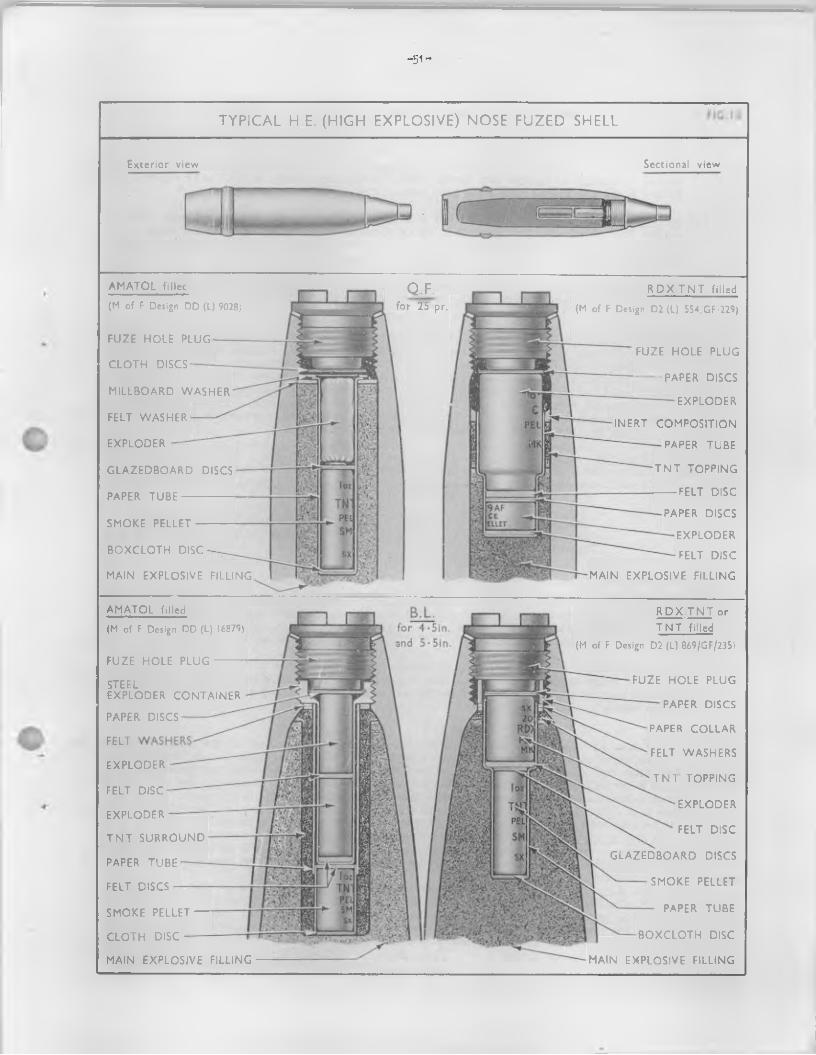
-51-
TYPICAL H E. (HIGH EXPLOSIVE) NOSE FUZED SHELL
Exterior view Sectional view
A M A TO L fillec
(M of F Design DD (L) 9028;
FU ZE H O LE PLUG
C L O T H DISCS
M ILLBOARD W A SH E R
FELT W ASHER
EXPLO DER
G L A Z E D B O A R D DISCS
PAPER T U B E --------
SM OKE PELLET -
B O X C L O T H DISC
MAIN EX PLO SIVE FILLING
Q.F.for 25 pr.
PAPER DISCS
EX PLO D ER
FELT DISC
MAIN EX P LO SIV E FILLING
R D X T N T filled
(M of F Design D2 (L) 554/GF/229)
FU ZE H O LE PLUG
---------- PAPER DISCS
EX PLO D ER
IN ER T CO M P O SITIO N
PAPER TU BE
T N T TO PPIN G
-------- FELT DISC
A M A TO L filled
(M of F Design DD (L) 16879)
FU ZE H O LE PLUG
STEELEX PLO D ER C O N T A IN E R
PAPER DISCS
FELT
EX PLO D ER
FELT DISC
EXPLO D ER
T N T SU R R O U N D
PAPER TU BE
FELT DISCS
SM OKE PELLET
C L O T H DISC
MAIN EX PLO SIVE FILLING
R P X /T N T or T N T filled
(M of F Design D2 (L) 869/GF/235)
FU ZE H O LE PLUG
PAPER DISCS
PAPER C O LL A R
FELT W ASHERS
T N T TO PPIN G
EX PLO D ER
FELT D ISC
G L A Z E D B O A R D DISCS
SM OKE PELLET
PAPER TU BE
B O X C L O T H DISC
MAIN EX PLO SIV E FILLIN G

- 5 2 -
. 218. The following complementary features w ill be found in F ield Branch A r t ille ry H.E. she11:-
(a ) Erploder_containers - A l l B.L. amatol f i l le d shell are fitted with a steel exploder container. B.L. 4*5 inch and 5.5 inch H.E. shell f i l le d amatol to design ED(L)19506 are fitted with a container, s tee l, No. 4 or 27, while B.L. 7.2 inch howitzer H.E. shell f i l le d amatol to design BD(L) 19507 are fitted with a container, steel. No. 3* A l l other B.L. amatol f i l le d shell are f itted with container, stee l, No. 1.
(b) Smoke boxes and pellets - Shell f it ted with red phosphorus smoke boxes have been fbund to suffer from phosphoric acid exudation owing to moisture entering badly sealed ones. A l l such smoke boxes are being replaced by a 1 oz. 8 dr. TNT/aluminium smoke p e lle t as smoke production is s t i l l an observation requirement o f Field Branch A rtille ry .
(c ) Surrounds and toppings - T.N.T. surrounds or toppings are used with amatol f i l l e d shell, waterproofing composition or T0N.T. toppings are used with R.D.X./T.N.T. f i ll in g s .
SHELL H.E. BASS FUzJlD219* Squash head •* Here the H.E., usually RDX/BWX or p lastic explosive, is contained in a very thin
walled shell. On h itting the armour, the shell oollapsea and the H.E. f i l l in g squashes up into a "plaster" on the face o f the plate. A base fuze is so designed that detonation takes place immediately this "plastering" action is complete, causing a scab to be blown o f f the inside o f the plate with considerable ve loc ity . The blast e ffec t on the outside is also very great and damage to the tracks, turret, ring, etc. is lik e ly to be caused. The plastering action is not materially affected by the angle o f incidence until I t becomes very large, and the performance o f this p ro jectile is , therefore, practically independent o f angle o f incidence.
(TAP’RTFR SHELL (F ig. 16)220. These contain a small bursting charge fbr the purpose o f opening the shell and liberating it s
contents. Such shell may be made to burst on impact or in the a ir . Typical f i l l in g s o f carrier shell are:-
Smoke (screening or coloured) Chemical (liqu id f i l le d )Flare (coloured; Star (with or without parachute)TnrMwifll a r y
Carrier shell are o f tro main types, v iz : -
(a ) Bursting shell - These are usually made to burst on impact by means o f a percussion fuze.The small bursting charge is su ffic ien t to break open the shell and release i t s contents.The main disadvantage o f this type o f shell is that, even with a d irect action foze, the contents are carried by remaining veloc ity into the ground, thus reducing their effectiveness.
(b) Ease ejection shell - The majority o f modern oarrler shell are o f this type. At the required point on the trajectory a time fuze ign ites the burster (expelling) charge which blows out the base o f the shell and e jects the contents; i t may also, as in the case o f, e .g ., smoke shell, ign ite the containers which i t e jects.
SHELL 3J0KE B.E. (F ig. 16)221. These are base ejection shell having a steel body and base. The head o f the shell, which nay be
fit te d with a separate head, is bored ani screw--threaded to receive a standard 2 inch time and percussion or time foze or a plug, fuze-hole, 2 inch No. 1. Immediately below the fuze-hole a diaphragm with a central hole is formed in the head, a tinned-plate disc being soldered over the hole.
A cavi-ty below the diaphragm acccunodates a gun-powder burster (expelling) charge contained in & shalloon bag. The smoke composition is contained in a number o f mild steel containers which have a perforated centra), tribe. The perforations permit the ign ition o f the composition which on burning is emitted through the same holes. A b a ffle plate is positioned between the burster charge and the upper smoke container. A hole through the centre o f the b a ffle plate is covered by a paper disc secured with shellac. The shell is closed by a ligh tly screwed in base assembled over millboard washers and, in certain designs, a oopper disc.
On the fuze functioning, the burster in the head o f the shell In ignited. The resulting flame passes through the hole in the ba ffle plate and down the central hole in the smoke containers, then passing through the perforations in the tike o f the containers i t ig i ite s the priming composition; at the same time the pressure on the surface o f the b a ffle plate causes the base o f the shall to be sheared-off am the containers ejected. The containers may be f i l le d with either screening smoke compositions or sn»ke mixtures giving a red, blue, groan or yellow colour. Smoke shell f i l l e d with coloured smoke mixtures are used mainly fo r target recognition and/or fo r signals. Containers o f d ifferen t colour composition are not mixed in the earns shell. The shell are marked, designated, accounted fo r and issued according to the individual characteristics o f the smoke produced.
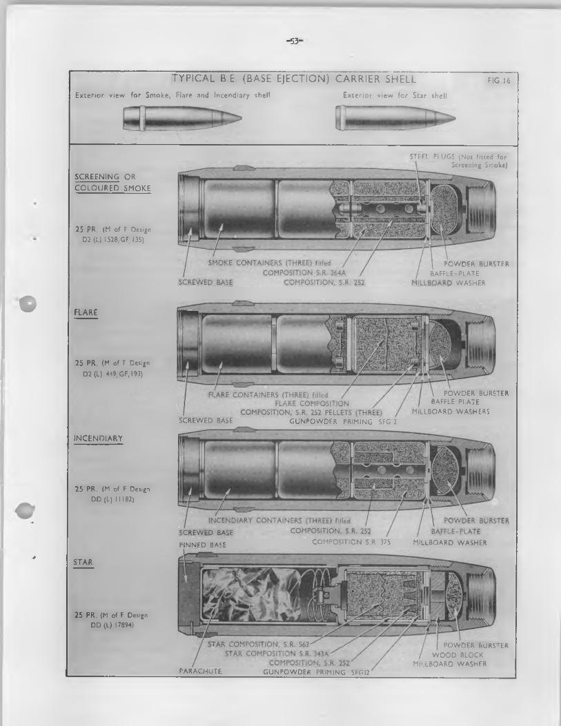
-53-
©
■*
TYPICAL B.E. (BASE EJECTION) CARRIER SHELLExterior view for Smoke, Flare and Incendiary shell Exterior view for Star shell
F IG .16
SC R EEN IN G OR
C O L O U R E D SMOKE
25 PR. (M of F Design D2 (L) 1528/GF, 135)
STEEL PLUGS (Not fitted for Screening Smoke)
SMOKE CONTAINERS (THREE) f.iledCOMPOSITION S.R. 264A
SCREWED BASE COMPOSITION, S.R. 252
POWDER BURSTER BAFFLE-PLATE
MILLBOARD WASHER
FLARE
25 PR. (M of F Design D2 (L) 449/GF/193)
IN C E N D IA R Y
25 PR. (M of F Design DD (L) 1 1 182)
STAR
25 PR. (M of F Design DD (L) 17894)
FLARE CONTAINERS (THREE) fdledFLARE COMPOSITION
COMPOSITION, S.R 252 PELLETS (THREE) SCREWED BASE GUNPOWDER PRIMING SFG 2
POWDER BURSTER BAFFLE PLATE
MILLBOARD WASHERS
PINNED BASE COMPOSITION S.R. 375 MILLBOARD WASHER
PARACHUTE GUNPOWDER PRIMING SFG 12
POWDER BURSTER W OOD BLOCK
MILLBOARD WASHER
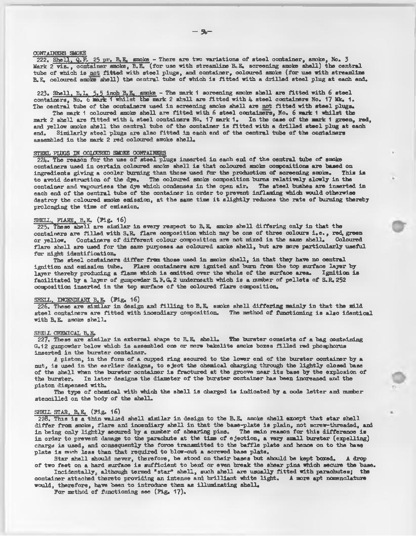
- 54~
CONTaINSRS smoke222. Shell,,. _Q» EV 25 pr3 B.E® smoke - There are two variations o f s tee l container, smoke, No. 3
Mark 2 v i z . , container smoke, B.E. ( fo r use with streamline BeE. screening smoke shell) the central tube o f which is not fit ted with steel plugs, and container, coloured smoke (fo r use with streamline B.E. coloured smoke shell) the central tube o f which is f itted with a d rilled steel plug at each end.
223. Shell. B.L» 3.5 inch B.B. smoke - The mark 1 screening smoke shell are f it te d with 6 steel containers, No. b Sark 1 whilst EKe’ nsark 2 shell are f it te d with 4 steel containers No. 17 Mk. 1.The central tube o f the containers used in screening smoke shell are not fit te d with s tee l plugSo
The mark 1 coloured smoke shell are f it te d with 6 steel containers. No. 6 mark 1 whilst the mark 2 shell are fit te d with 4 steel containers No. 17 mark 1. In the case o f the mark 1 green, red, and yellow smoke shell the contra! tub© o f the container is f it te d with a d rilled s tee l plug at each end. Sim ilarly steel plugs are also f it te d in each end o f the central tube o f the containers assembled in the mark 2 red coloured smoke shell.
STEEL PLUGS IN COLOURED SMOKE CONTAINERS224. The reason fo r the use o f steel plugs inserted in each end o f the central tube o f smoke
containers used in certain coloured smoke shell is that coloured smoke compositions are based on ingredients giving a cooler burning than those used for the production o f screening smoke. This is to avoid destruction o f the dye. The coloured smoke composition burns re la tive ly slowly in the container and vapourises the dye which condenses in the open a ir. The steel bushes are inserted in each end o f the central tube o f the container in order to prevent inflaming which would otherwise destroy the coloured smoke emission, at the same time i t s ligh tly reduces the rate o f burning thereby prolonging the time o f emission.
SHELL. FLARE, B.E. (P ig . 16)223. These shell are similar in every respect to B.E. smoke shell d iffer in g only in that the
containers are f i l le d with S.R. flare composition which may be one o f three colours i . e , , red, green or yellow. Containers o f d ifferent colour composition are not mixed in the same shell. Coloured fla re shell are used fo r the same purposes -as coloured smoke shell, but are more particu larly useful for night identification .
The steel containers d if fe r from those used in snoke shell, in that they have no central ign ition and emission tube. Flare containers are ignited and bum from the top surface layer by layer thereby producing a flame which is emitted over the whole o f the surface area. Ign ition is fa c ilita ted by a layer o f gunpowder S.F.G.2 underneath which is a number o f p elle ts o f S.R.252 composition inserted in the top surface o f the coloured fla re composition.
SHELL. INCENDIA3I B.E. (P ig . 16)226. These are similar in design and f i l l in g to B.E. smoke shell d iffer in g mainly in that the mild
steel containers are fit te d with incendiary composition. The method o f functioning is also identical with B.E. smoke shell.
SHtilL CHEMICAL B.E.227. These are similar in external shape to H.E, shell. The burster consists o f a bag containing
G„12 gunpowder below which is assembled one or more bakelite smoke boxes f i l le d red phosphorus inserted in the burster container.
1 . piston, in the form o f & cupped ring secured to the lower end o f the burster container by & nut, is used in the ea r lie r designs, to e ject the chemical charging through the ligh tly closed base o f the shell when the burster container is fractured at the groove near i t s base by the explosion of the burster. In la te r designs the diameter o f the burster container has been increased and the piston dispensed with®
The type o f chemical with which the shell is charged is indicated by a code le tte r and number stencilled on the body o f the shell.
SHELL STAR. B.E. (P ig . 16)22$T"This is a thin wallsd shell similar in design to the B.E. smoke shell except that star shell
d iffe r from smoke, fla re and incendiary shell in that the base-plate is plain, not screw-threaded, and in being only ligh tly secured by & number o f shearing pins. The main reason fo r th is difference is in order to prevent damage to the parachute at the time o f ejection , a very small burster (expelling) charge is used, and consequently the force transmitted to the b a ffle plate and hence on to the base plate is nairch less than that required to blow-out a screwed base plate.
Star shell should never, therefore, be stood on th e ir bases but should be kept booced. A drop o f two feet on a hard surface is sufficient to bend or even break the shear pins which secure the base.
Incidentally, although termed "star" shell, such shell are usually fit te d with parachutes; the container attached thereto providing an intense and b r illian t white ligh t. A more apt nomenclature would, therefore, have been to introduce them as illuminating shell.
For method o f functioning see (T ig. 17)«
- 5 5 -
METHOD OF FUNCTIONING, BASE EJECTION STAR SHELL FIG.87
PRACTICE PROJECTILES229o Practice projectiles are vised for practice fir in g , training in accuracy and spotting* They
are usually o f the H.E* type o f shell except that the f i l l in g is an inert substance such as sand or H*E* substitute (abbreviated HE.SUB) although special enpty projectiles may be approved*
Chapter 5
Projectiles
Section 3 Shot
*
•GENERAL2^0. The term "shot" applies to pro jectiles containing no explosive as the main f i l l in g or bursting
charge although most shot are f it te d with tracers to assist observation o f their f ligh t.Armour niercing shot are provided fo r use in anti-tank or anti-ship role fo r the attack o f
armour, concrete, etc*Penetration o f amour by shot causes damage in proportion to the remaining forward and
rotational velocity o f the shot and the confinement o f space beyond the armour o f the target*Additional damage is also in flic ted by the projection o f the "plug” o f armour ahead o f the shot, occasional break-up o f the shot during penetration, flaking o f the armour and by concussion*
Generally speaking, the thicker the armour to be penetrated, the higher mist be the remaining velocity . At a certain velocity , however, the head o f the steel shot wall shatter before penetrating* In fact tr ia ls have shown that a given shot w il l shatter say, 2,500 f .s . against a plate which i t penetrates at, say, 2,200 f .s . Hence the re la tive effectiveness o f AP and APC shot.
ARMOUR PIERCING (A ,? .) (P ig.18)231* AoPo shot are o f forged steel and pointed, the radius o f the head being usually less than two
calibres as a more pointed head tends to break upon inpact* The head is hardened to penetrate the target but the hardness decreases progressively towards the base in order to allow increased toughness to the body and thus reduce the incidence o f break up. I t has the highest possible piercing performance which is obtainable under the conditions o f manufacture.ARMOUR PIERCING. CAPPED (A.P.C) (Fig.18)232. A.P.C, shot - are A.P. shot fit ted with a penetrative cap of hardened a lley steel whose function
is to assist the point o f the shot at the moment o f inpact and help i t s entry into the plate. The cap increases the maximum penetrative performance o f the shot considerably.
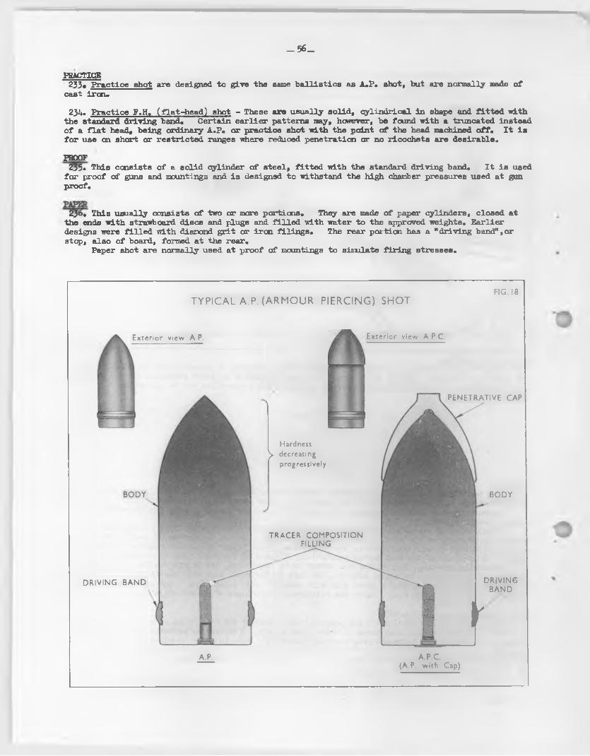
— 56_
PRACTICE233« Practice shot are designed to give the same b a llis tics as A.P. shot, but are normally made o f
cast iron*
234. Practice F.H, ( flat-he ad) shot - These are usually solid, cylindrical in shape and f it te d with the standard driving band« Certain ea rlie r patterns may, however, be found with a truncated instead o f a f la t head, being ordinary A.P* or practice shot with the point o f the head machined o ff* I t is fo r use an short or restricted ranges where reduced penetration or no ricochets are desirable.
PROOF235* This consists o f a solid cylinder o f stee l, f it te d with the standard driving band* I t is used
fo r proof o f guns and mountings and is designed to withstand the high chamber pressures used at gun proof*
23°* This visually consists o f two or mare portions. They are made o f paper cylinders, closed at the ends with strawboard discs and plugs and f i l le d with water to the approved weights* Earlier designs were f i l le d with diamond g r it or iron filin gs* The rear portion has a "driving band",or step, also o f board, formed at the rear*
Paper shot are normally used at proof o f mountings to simulate fir in g stresses*
TYPICAL A.P. (ARMOUR PIERCING) SHOTFIG.18
Exterior view A.P.
D R IV IN G B A N D
A.P.
Exterior view A.P.C.
Hardness y decreasing
prog ressively
T R A C E R CO M PO SITIO N FILLIN G
P E N ETR A TIV E CA P
B O D Y
D R IV IN GBA N D
JA .P.C.
(A.P. with Cap)
- 5 7 -
Chapter 6
Fuzes
Section i. Principles etc.
INTRODUCTION237* In general, a fuze acts in conjunction with an exploding system, to ensure the correct
functioning o f the bursting charge in a pro jectile , bomb or mine.By fa r the greatest variety o f fuzes are to be found in projectiles fired from a r t ille ry
weapons. These may be classified in a number o f ways, thus: -
(a ) According to function
( i ) "Time” - to function a fte r a predetermined time; these are subdivided into "mechanical” and "combustion" according to the method o f operation.
( i i ) "Proximity" - to function on nearing the target.
( i i i ) "Percussion graze" - to function on appreciable deceleration.
( iv ) "Percussion direct action" - to function on impact.
(b ) According to position in the projectile
( i ) "Nose" - shaped to conform to the shell contour at the nose.
( i i ) "Base" - cylindrical in shape, fo r entry into the base o f the shell cavity.
Nose fuzes have a right-hand and base fuzes a left-hand screw thread, to avoid the possib ility o f their becoming unscrewed by rotational acceleration in the bore. An exception to this rule is provided by nose fuzes in 2 inch mortars and bomb throwers. Here, rotational effects are negligible, and the use o f a left-hand thread prevents the fuze from being unscrewed with the protecting cap (which has a right-hand thread).
(c ) According to f i l l in g
( i ) "Igniferous" fuzes have a magazine f i l le d with gunpowder, to give a flash: these fuzes are not usually employed in H.E. shell unless the f i l l in g is provided with a p icric powder exploder.
( i i ) "Detonating" fuzes have a magazine f i l le d with a p e lle t o f C.E. A small channel, f i l le d with ligh tly stenmed C.E., connects from the detonator to the magazine, so that when the detonator is fired , this continuous column o f explosive builds up a detonating impulse.
Although particular types o f fuzes are considered separately, one or more types may be combined into a single fuze, e .g . "time and percussion", "d irect action and graze", etc.
FORCES238. A ll components o f fuzes are either fixed re la tive ly to the fuze or are free to move within
certain lim its. The movement o f the free components, controlled or restrained as necessary by fr ic t io n and/or springs, depends principally upon the forces arising from acceleration, deceleration and spin, although i t is also affected by "side-slap" to an extent depending mainly upon the state o f wear o f the guns.
Some or a l l o f these forces are u tilised to ensure correct operation as well as in various safety devices.
239« Nose Fuzes - The d irect action type are normally "aimed" by:-
(a ) Set-back force or
(b) Centrifugal fbree or
(c ) A combination o f both.
- 5 8 -
Set back force acta on the free or movable parts o f the faze at the instant o f fir in g . Centrifugal force is intended to be e ffec tive only when deceleration occurs on the projectile leaving the bore, when the free or moving parts are forced-outwards by spin. While passing through the bore the moving parts are expected to remain in their original positions ty friction as a result o f set-back.
The majority o f fuzes incorporate shutters which move into th® "armed" position by the influence o f centrifugal force. Such shutters are usually designed to remain in the "unarmed" or safe position until the shell is spinning between a specific number o f revolutions per minute (r.p.m .) the number o f revolutions varying in d ifferent fuzes to meet the requirements o f the equipments, for which they are approved. Springs assembled either under compression or expansion may be used to assist or restrain the centrifugal force.
Locking devices may also be incorporated to secure the movable components in the armed position after centrifugal force becomes e ffec tive .
In certain new fuzes a delayed arming shutter actuated hy centrifugal force is incorporated in the design. See para. 247(c).
The "time" element o f time (combustion and mechanical) fuzes and in some instances the "self-destruction" element, is in itia ted at the instant o f fir in g by set-back (that is , the e ffec t o f in e r tia ).
240. Base fuzes - The direct action type are normally "armed" in a manner similar to that described above.
A "delay" action, which becomes e ffec tive after impact, may be incorporated. Later designs may incorprate a delayed arming mechanism.
241. Acceleration and deceleration - The acceleration o f the p ro jectile and fixed components tends to leave the free moving components behind. I f the acceleration is moderate, the loose parts "creep back" or i f violent, "set-back". Conversely, deceleration causes "creep forward" or "set forward".
Violent acceleration occurs at the instant o f fir in g the gun, and comparatively moderate acceleration with the subsequent forcing o f the p ro jectile along the bore o f the gun. Moderate deceleration continues from the moment the projectile leaves the muzzle until i t becomes violent on impact. Violent and momentary deceleration also occurs with a worn gun with appreciable free run-up when the driving band f ir s t takes up the r if l in g .
242. Spin - Centrifugal force, resulting from the rotation of the shell, acts in a plane at right angles to the line o f f ligh t to force the free components outwards from the centre of the fuze.
Centrifugal force is not normally intended to be e ffective until the shell has le f t the bore o f the gun as the free components are expected to be held in their original positions by frictiona l forces proportioned to the set-back forces in the gun.
243. Side-alap - Forces acting in a plane roughly at right angles to the axis o f the bore are also set up owing to inadequate centring o f the p ro jectile . This causes the shoulder o f the p ro jectile to h it against the bore o f the gun.
These forces, however, are only appreciable with a well worn gun, and in this case the excessive hammering, is known as "side-slap". With the more modern high velocity guns this tendency is restricted i f not eliminated ty the fit t in g o f double driving bands to the p ro jectile .
MECHANICAL DEVICES244. General - A ll fuses embody devices to ensure:-
Safety in handling, both before and during loading.Bore and muzzle safety inmediately after fir in g .Arming a fter leaving the muzzle.Firing o f fuze magazine and in itia tion o f the bursting charge in the shell.
The above devices are housed in the fuze body. For time fuzes, the fuze body also contains the time element, for proximity fuzes, the proximity element, and for self-destruction, the s e lf-destruction element.
245. Arming of the fuze - This is a mechanical event which is designed to take place as the shell is fired ' ( i . e . time_ fuzes) or after the shell leaves the muzzle o f the gun ( i . e . percussion fuzes). Before the fuze in "armed" i t should not be capable o f being put into operation by any conceivable rough usage, or by any drop in any position which is lik e ly to occur in the Service. Generally speaking, the moving parts of a fuze are securely locked together by a number o f devices, and the particular combination o f forces which the fuze undergoes when being projected from a gun is used to unlock them. Any other combination o f forces would not have the required e ffec t. I t is in facta form o f combination lock in which fir in g from a r i f le d weapon is the key.
The ultimate object o f the mechanical devices is to ensure that the detonator is struck at the desired instant. Premature action is prevented by various forms o f holding and locking devices,
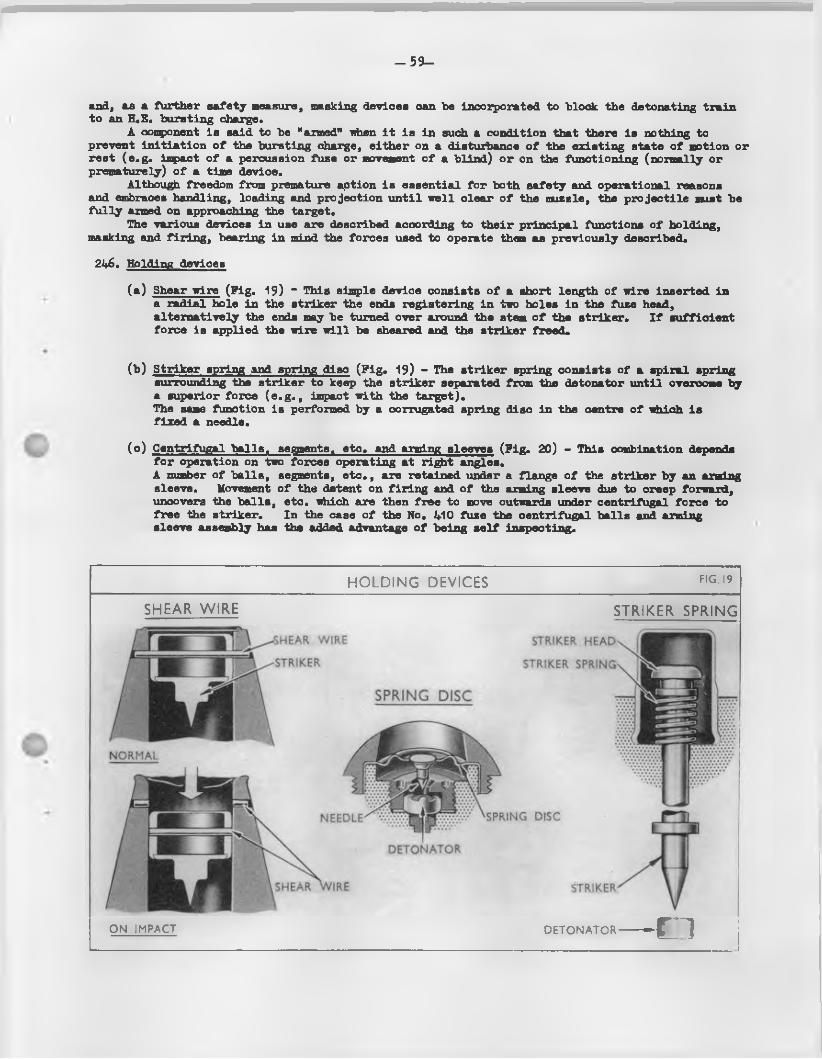
- 5 9 -
and, as a further safety measure, masking devices can be incorporated to block the detonating train to an H„E. bursting charge.
A component is said to be "armed" when i t is in such a condition that there is nothing to prevent in itia tion o f the bursting charge, either on a disturbance o f the existing state o f motion or rest (e .g . impact o f a percussion fuze or movement o f a blind) or on the functioning (normally or prematurely) o f a time device.
Although freedom from premature action is essential fo r both safety and operational reasons and embraces handling, loading and projection un til well clear o f the muzzle, the pro jectile must be fu lly armed on approaching the target.
The various devices in use are described according to their principal functions o f holding, masking and fir in g , bearing in mind the forces used to operate them as previously described.
22*6. Balding devices
(a ) Shear wire (P ig. 19) “ This simple device consists o f a short length o f wire inserted in a radial hole in the striker the ends registering in two holes in the fuze head, alternatively the ends may be turned over around the stem o f the striker. I f su fficient force is applied the wire w ill be sheared and the striker freed.
(b ) Striker spring and spring disc (P ig . 19) - The striker spring consists o f a spiral spring surrounding the striker to keep the striker separated from the detonator until overcome by a superior force (e .g . , impact with the target).The same function is performed by a corrugated spring disc in the centre o f which is fixed a needle.
(c ) Centrifugal ba lls , segments, etc, and arming sleeves (P ig. 20) - This combination depends fo r operation on two forces operating at right angles.A number o f ba lls , segments, e tc . , are retained under a flange o f the striker by an arming sleeve. Movement o f the detent on fir in g and o f the arming sleeve due to creep forward, uncovers the balls, etc. which are then free to move outwards under centrifugal force to free the striker. In the case o f the No. 410 fuze the centrifugal balls and arming sleeve assembly has the added advantage o f being s e lf inspecting.
HEAR W IRE STRIKER H EA D
STRIKER STRIKER SPRING
SPRING DISC
NORM AL
SPRINGN EED LE
D E T O N A T O R
SHEAR W IRE STRIKER
HOLDING DEVICES F IG .I9
SHEAR WIRE STRIKER SPRING
O N IM PACT D E T O N A T O R — C l
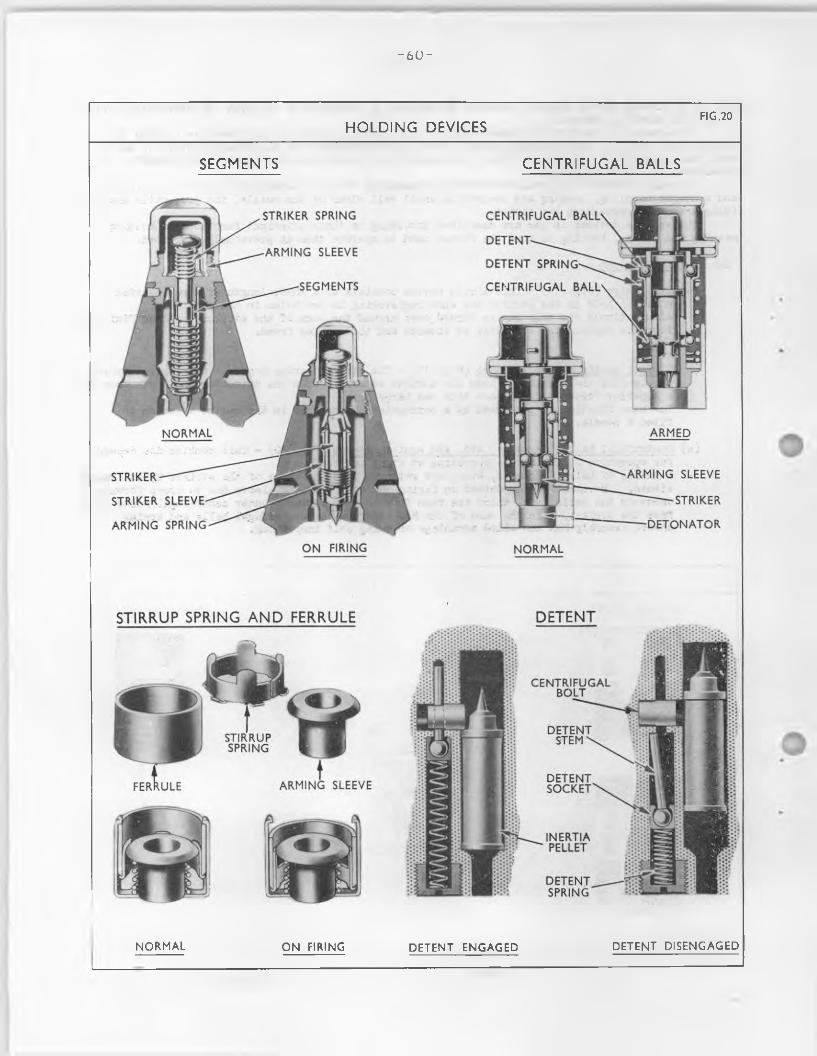
- 6 0 -
STRIKER SPRING C E N T R IF U G A L BALL'
D E T E N T ARM IN G SLEEVE
D E T E N T SPRING'
SEGM EN TS C E N T R IF U G A L B A L L
ARM EDN O RM A L
A RM IN G SLEEVESTRIKER
STRIKERSTR IK ER SLEEVE
D E T O N A T O RA RM IN G SPRING
O N FIRING N O RM A L
DETENTSTIRRUP SPRING AND FERRULE
C E N T R IF U G A LBO LT
D E T E N T STEM ^STIRRUP
SPRING
D E T E N TSO C K E TA RM ING SLEEVE
IN ERTIAPELLET
D E T E N TSPRIN G
HOLDING DEVICESFIG.20
SEGMENTS CENTRIFUGAL BALLS
N O RM A L O N FIRING D E T E N T E N G A G E D D E T E N T D IS E N G A G E D
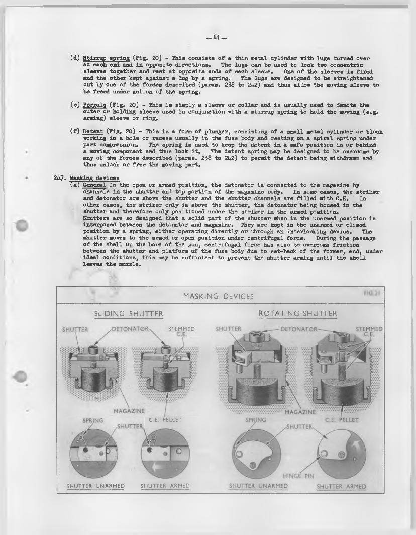
—61 —
(d) Stirrup spring (P ig. 20) - This consists o f a thin metal cylinder with lugs turned over at each end and in opposite directions. The lugs can he used to lock two concentric sleeves together and rest at opposite ends o f each sleeve. One o f the sleeves is fixed and the other kept against a lug by a spring. The lugs are designed to be straightened out by one o f the forces described (paras. 258 to 242) and thus allow the moving sleeve to be freed under action o f the spring.
(e ) Ferrule (P ig . 20) - This is simply a sleeve or co lla r and is usually used to denote the outer or holding sleeve used in conjunction with a stirrup spring to hold the moving (e .g . arming) sleeve or ring.
( f ) Detent (P ig. 20) - This is a form o f plunger, consisting o f a small metal cylinder or block working in a hole or recess usually in the fuze body and resting on a spiral spring under part compression. The spring is used to keep the detent in a safe position in or behinda moving component and thus lock it * The detent spring may be designed to be overcome by any o f the forces described (paras. 238 to 242) to permit the detent being withdrawn and thus unlock or free the moving part.
247. Masking devices(a ) General In the open or aimed position, the detonator is connected to the magazine by
channels in the shutter and top portion o f the magazine body. In some cases, the striker and detonator are above the shutter and the shutter channels are f i l le d with C.E. In other cases, the striker only is above the shutter, the detonator being housed in the shutter and therefore only positioned under the striker in the aimed position.Shutters are so designed that a solid part o f the shutter when in the unarmed position is interposed between the detonator and magazine.. They are kept in the unarmed or closed position by a spring, either operating d irec tly or through an interlocking device. The shutter moves to the armed or open position under centrifugal force. During the passage o f the shell up the bore o f the gun, centrifugal force has also to overcome fr ic tion between the shutter and platform o f the fuze body due to set-back o f the former, and, under ideal conditions, this may be sufficient to prevent the shutter arming until the shell leaves the muzzle.
SLIDING SHUTTER
MASKING DEVICES
ROTATING SHUTTER
STEMMED
C .E . PELLET
SHUTTER UNARMED SHUTTER ARMED
SH U TTER D E T O N A T O R STEMMEDC.E.
M A G A ZIN EC .E. PELLET
•SHUTTER
H IN G E PIN
SHUTTER UNARMED SHUTTER ARMED
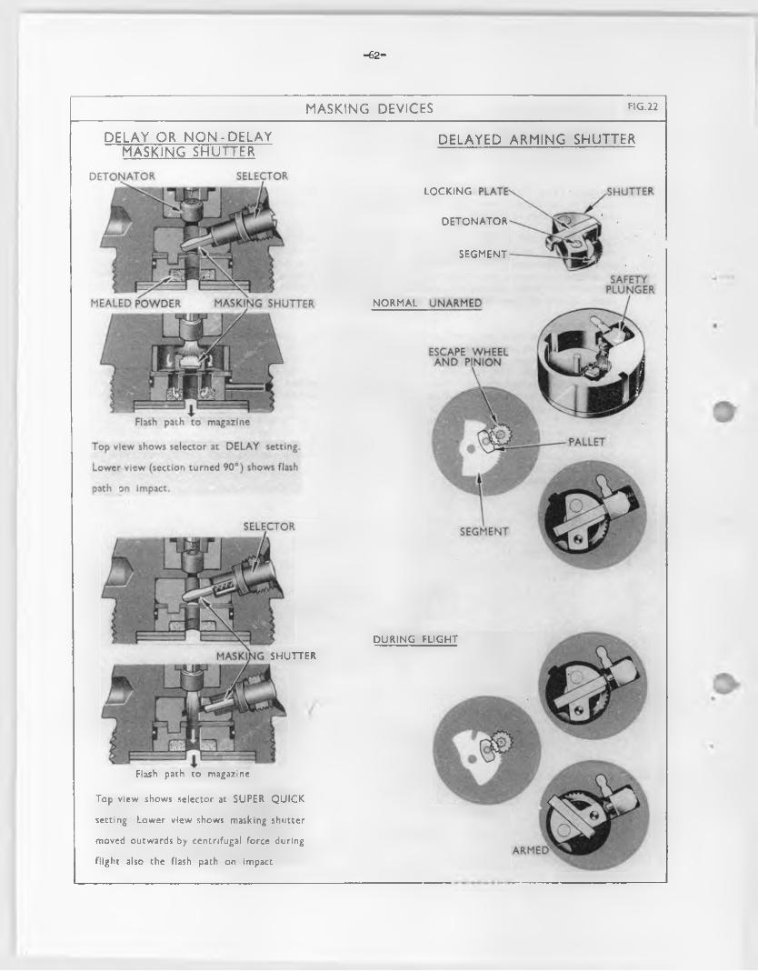
-62-
SELECTO RD E T O N A T O R
M EALED P O W D ER M A SKIN G SH U TTER
SAFETYP LU N G ER
ESCAPE W H EE L A N D PINION
PALLET
SEG M EN T
MASKING DEVICES FIG .22
DELAY OR N O N -D ELA Y MASKING SHUTTER
DELAYED ARMING SHUTTER
SH U TTER
Flash path to magazine
Top view shows selector at SUPER Q U IC K
setting. Lower view shows masking shutter
moved outwards by centrifugal force during
flight also the flash path on impact
L O C K IN G
D E T O N A T O R
SEG M EN T
N O RM A L U N ARM ED
D U R IN G FLIG H T
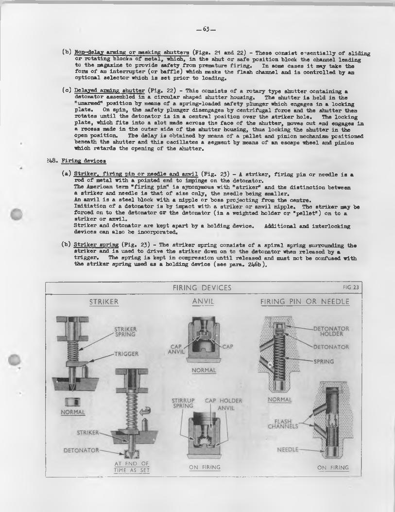
- 6 3 -
(b ) Non-delay aiming or masking shutters (Pigs. 21 and 22) - These consist essentially o f sliding or rotating blocks o f metal, which, in the shut or safe position block the channel leadingto the magazine to provide safety from premature fir in g . In sows cases i t may take the fora o f an interrupter (o r b a ffle ) which masks the flash channel and is controlled by an optional selector which is set prior to loading.
(c ) Delayed arming shutter (P ig. 22) - This consists o f a rotary type shutter containing a detonator assembled in a circular shaped shutter housing. The shutter is held in the "unarmed" position by means o f a spring-loaded safety plunger which engages in a locking plate. On spin, the safety plunger disengages by centrifugal force and the shutter then rotates until the detonator is in a central position over the striker hole. The locking plate, which f i t s into a slot made across the face o f the shutter, moves out and engages in a recess made in the outer side o f the shutter housing, thus locking the shutter in the open position. Tb.e delay is obtained by means o f a pallet and pinion mechanism positioned beneath the shutter and this oscillates a segment by means o f an escape wheel and pinion which retards the opening o f the shutter.
22*8. Firing devices
(a ) Striker, f ir in g pin or needle and anvil (P ig . 23) - A striker, fir in g pin or needle is a rod o f metal with a pointed end to impinge on the detonator.The American term " f ir in g pin" is synonymous with "striker" and the distinction between a striker and needle is that o f size only, the needle being smaller.An anvil is a steel block with a nipple or boss projecting from the centre.In itia tion o f a detonator is by impact with a striker or anvil nipple. The striker may be forced on to the detonator or the detonator ( in a weighted holder or "p e lle t" ) on to a striker or anvil.Striker and detonator are kept apart by a holding device. Additional and interlocking devices can also be incorporated.
( t ) Striker spring (P ig . 23) - The striker spring consists o f a spiral spring surrounding the striker and is used to drive the striker down on to the detonator when released by a trigger. The spring is kept in compression until released and must not be confused with the striker spring used as a holding device (see para. 246b ).
D E T O N A T O RH O LD ER
STRIKERSPRING
C A P x A N V IL
D E T O N A T O RT R IG G ER
SPRIN G
N O RM A L
N O RM A LSTIRRUPSPRING
CA P HO LDER A N V IL
N ORM AL
FLASHC H A N N E L S
STRIKER
N EED LED E T O N A T O R
FIRING DEVICES FIG .23
STRIKER ANVIL FIRING PIN OR NEEDLE
A T E N D OF TIME AS SET O N FIRING O N FIRING
- 6 4 -
(c ) Hammer (F ig. 24) - This is usually a rod with enlarged head and is mounted in front o f the striker and used to "hammer" the striker on to the detonator.The hammer is often used with very sensitive fuzes designed to function on striking on aircra ft fabric or skin.The sensitiv ity o f the fuze can be reduced by having a thin diaphragm formed in the fuze head above the hammer. The shape o f the hammer head and thickness of the diaphragm is somewhat c r it ic a l. I f such a fuze is too sensitive i t may function on impact with raindrops.In some cases, the hammer and striker are combined in one piece and the combined hammer and striker is then termed a "hammer".
(d) Inertia pellet (F ig. 24) - This is a metal weight, usually cylindrical in shape and can be used to house a detonator and carry i t on to a striker or anvil. A lternatively, i t can be fitted with a striker, in which case the pe lle t moves forward to impinge on the fixed detonator.
OTHER FUZE CCMPONENTS249. Pellets - These are formed of pre-pressed explosive, both C.E. and gunpowder pellets being used.
Powder pellets are sometimes perforated, in which case they serve to reinforce flash, or theymay be solid and in this form constitute a delay.
250. Detonators (F ig. 25) - These are either igniferous or disruptive according to whether they are required to ignite powder or detonate C.E. respectively.
Detonators consist o f small copper cups or shells containing the explosive, closed by a thin metal disc and a brass washer secured usually by turning over the l ip or lugs formed on the mouth of the cup. In more recent designs o f fuzes, lugless detonators may be assembled therein. Certain detonator cups are tinned whilst others may be made o f aluminium.
Detonators are normally in itiated by the needle point o f the striker piercing the detonator i . e . by fr ic tion , but occasions occur where they may be in itia ted by a flash from another source, e.g. a powder pe lle t or another detonator. Caps (in the case o f primers and tracer ign iters) on the other hand are in itia ted by the rounded end o f a striker being driven on to the base o f the cap and causing the composition to be "nipped" between two metal surfaces, i . e . the base o f the cap and rounded end or boss o f an anvil.
FIRING DEVICES FIG .24
HAMMER INERTIA PELLET
N O RM A L
O N IM PACT
- 6 5 -
-B R A S S D ISC-—
BRASS W A SH ER
D E T O N A T O R CU P
LEA D A Z ID E 3 GRS
DETONATORS FIG .25
D ETO N A TO R S? GR A.Z.) DETONATORS GR. A .Z .)
D E T O N A T IN G CO M PO SITIO N
( 2 - 7 GRS.A M IX TU R E)
D E T O N A T IN G CO M P O SITIO N
( 2 GRS.A.I. M IX T U R E)
MAGAZINE AND CHANNELS
Channels filled with STEMMED C.E.
M A G A ZIN E
M A G A Z IN E CAP
D E T O N A T O R Shutter in armed position
E. PELLETir*g)
P O W D ERPELLETS Channel
M A G A ZIN E
BASE PLUG
PO W D ER(Igniferous)'
BO DY
Compressed powder train in tim e ring
251. Magazine (F ig. 26) - This can be fdlnsd either in the body o f the fuze, or can be a separate container secured in or to the body.
I t may be either igniferous or detonating according to whether i t is f i l le d with powder to produce a flash or with CoE. to detonate an H.E. charge.
252. Channels (F ig. 26) - These connecting links may contain loose powder, compressed powder, pellets o f powder or C.E., or may be empty and merely serve the purpose o f flash direction.
Channels f i l le d C.E. or similar high explosive are used to ensure substantial continuity o f the detonating train.
253. CapB - These may be or two kinds, an inner one (normally known as a striker cover) to protect and prevent interference with the head o f the striker, to act as a windshield and also to prevent moisture, g r it , ete- entering the nose o f the fuze. This is not removable. The other is an outer or "safety cap" designed to protect the nose o f the fuse in transit and handling but intended to be removed at the time o f loading the p ro jectile in the gun.
- 6 6 -
254. Delay systemsDelay in fuze8 nay be fixed or optional and is attained in three ways:-
(a ) by interposing a b a ffle in a flash channel to force the flash to follow a tortuous path*
(b ) by interposing a layer o f solid pyrotechnic material which must be burnt through to allow the flash to proceed on it s way.
(c ) by incorporating a delay mechanism which prevents shutter from becoming armed until the p ro jectile is clear o f the muzzle o f the gun.
Having regard to the characteristics o f detonation, i t w i l l be evident that delay can only be obtained in the igniferous train of a fuze and not in the disruptive train. Consequently a disruptive fuze can normally only have delay incorporated i f the early part o f the explosive train is igniferous. An exception to this rule occurs, however, in detonating fuzes f it te d with a delayed arming shutter0 ( i „ e „ , fuze, perc. base medium L. 15)* Systems (a ) and (b) above may also be employed together.
TTMF, RJZTCS255. General - Time fuzes are set fo r time before loading by rotation o f a moving portion o f the
fuze against the fixed fuze body by means o f a fuze key, fuze setter or fuze setting machine. Graduations are provided to enable the setting to be set by hand. In some la tte r designs, however, the graduations are omitted because the fuzes are always set by mechanical fuze setter.
The time element may be either o f the combust ion or mechanical type.The bottom portion o f the fuze body generally forms a platform upon which the moving part
rotates fo r setting the time o f functioning., With B ritish fuzes, the fixed part is e ither graduated in arbitrary fuze lengths fo r reading against an indicator on the moving part, or else the moving portion is made to operate a fuze length indicator on the fixed part. In addition, bothfixed aid moving parts have slots fo r the engagement by the pawls o f fuze keys or the older fuze setting machines. These slots are also used fo r setting the fuze at "SAPS". The latest fuze setting machines grip the fuze by means o f knife rings.
The moving portion must be tigh t enough to prevent movement in handling, transport, loading and fir in g , and yet su ffic ien tly loose to permit setting by the fuze key, fuze setter or fuze setting machine. The maintenance o f the correct stiffness or tension is important*
"Time” refers to the length of time from the instant o f f ir in g the weapon to the instant o f functioning o f the fuze.
(a ) Mechanical - This type o f fuze normally has a fu lly wound-up clock-work mechanism retained by a tr igger, which is released by the "set-back" on acceleration, a fte r which the mechanism works until the movement o f i t s parts releases a striker which is driven on to the detonator by a spring. The time between the starting o f the mechanism and the release o f the striker can be varied by the "setting" o f the fuze. In modern designs a direct action percussion head may also be fittedo In certain fuzes, however, the time mechanism may be functioned by centrifugal force.
(b) Combustion - In the combustion type o f fuze the detonator, in a suitable holder, is supported on a stirrup or coiled spring su ffic ien tly weak to allow the holder to "set-back* on acceleration, bringing the detonator on to a needle. The resultant flash ign ites a gunpowder p e lle t which, in turn,igjoites the composition in the time ring(s )»These fuzes embody a train o f compressed powder which bums through until the time as set has expired. The flash then fire s a magazine.The powder is generally contained in circumferential grooves in adjacent time rings, the powder burning in one ring until i t can ign ite the powder in the other, depending upon the re lative position o f the two rings as determined by the setting.Two rings are usually employed, the upper ring being fixed by pinning to the stem o f the fuze body, and the other movable, or "free" to rotate on the stem. The under surface of both rings is grooved fo r almost the entire circumference, the grooves being charged with fuze powder tinder compression.
6
Fuzes
Section 2. Types
- 67“
The upper ring has a rad ia l channel from one end o f the powder groove to p ick up the flash from the detonator, the channel containing a perforated powder p e lle t to fa c i l i t a t e th is function* A second channel to the outside o f the ring forms a gas escape, being f it te d with a small closing disc to provide a watertight cover, and a perforated powder p e lle t to blow the disc c lea r when ignited*The lower ring d if fe rs only in having a v e r tic a l channel (instead o f a rad ial channel) to pick tip the flame from the powder grooves in the tipper ring*The central stem or body contains the detonator, needle and magazine*Cloth washers are placed below the two rings to ensure a t igh t jo in t.Both rings are secured by a cap which is screwed on to the stem o f the fuze and bears down on to the rings to secure the necessary tension*
TIME AND PERCUSSION FUZES"256. These are time fuzes in which a percussion mechanism is embodied*
PERCUSSION FUZES257« General - Percussion fuzes are o f various types according to the speed o f action required*
Generally speaking, the d irect action fuze has the fastest action, followed c lose ly by the graze fuze and f in a lly by the delay action graze fuze.
The essentia l elements o f percussion fuzes are the f ir in g mechanism accompanied by the holding and safety devices* These have already been described in d e ta il in para. 246.
A self-destruction device is necessary fo r shell f i t te d w ith percussion fuzes, when used in the A*A* ro le , to prevent functioning o f the fuze on impact with the ground should the target be missed* Such a device may be embodied in the fuze as a time element.
The term "delay" when used in conjunction with percussion fuzes re fers to the action at the instant o f inpact.
(a ) Direct action (D.A*) fuzes - These fuzes may be o f the ignifercus or detonating types, the mechanism consisting o f a needle supported on a thin metal d isc, or a hammer or str iker supported on a shearing wire or co iled spring, exposed to a d irect blow on inpact with the target; i t s sen s it iv ity depending on the strength o f d isc, shearing wire or co iled spring* I t may be provided with a safety pin o r tape, arming sleeve and segments retain ing the str iker in a safe position , and also usually a shutter.D.A. fuzes f i l l e d C.E. are instantaneous in th e ir action while D.A* fuzes f i l l e d gunpowder have a s ligh t delayed action*
(b ) D irect action inpact (D, A. L ) fuzes - These fuzes may be o f the igniferous or detonating types, they d i f fe r mainly from the D.A* in being less sensitive . The mechanism usually consists o f a s tee l hammer supported on a stout shearing p in ; a shutter is a lso usually enfcodied.
(c ) Graze fuzes - The in te r io r mechanism o f graze fuzes is so arranged that when the sh ell is checked in f l ig h t or receives an appreciable deceleration, a movable part, usually called the graze, or in e rtia p e lle t can move forward to carry the detonator on to the needle (o r vice versa).A creep spring keeps the two apart u n til th is deceleration is experienced*As the movement o f the in e rtia p e lle t or weighted needle gives r is e to an " a ir gap" the fuze detonator is o f the flash type*Graze fuzes have a small inherent delay.
BASE HJZES25b. Wiese fuzes usually depend on a detonator in an in e rt ia p e lle t being driven on to a fix ed
needle (o r vice versa) by the sudden retarding o f the p ro je c t ile at the moment o f inpact * A delay may be incorporated. Later designs may incorporate a delayed arming mechanism.
PROXIMITY OR VARIABLE TIME (V* T* ) RJZES259* These are automatic time fuzes that require no accurate time setting. They are designed to
detonate the sh ell at the optimum le th a l distance from the ta rge t, provided that, in the case o f A.A* targets, the tra jec to ry passes su ff ic ie n tly close* The present day a r t i l le r y V.T. fuze in Service use is essen tia lly a combined self-powered radio transmitting and receiv ing unit* In f l ig h t , the armed fuze transmits radio waves. Unlike radar devices, the waves are sent continuously and a re non-directional* The radio wave fron ts which are re flec ted back to the fuze, from any suitable re fle c t in g surface ( e . g . , the ground or a ir ta rg e ts ), in teract with the transmitted waves* When th is intersection o f transmitted and re flec ted waves, resu lting in ripp les or beats, reaches a predetermined in tens ity , an electronic switch is tripped which then permits an e le c tr ic charge in the f ir in g capacitor (condenser) to flow through an e le c t r ic f ir in g squib, detonating the f i l l i n g in the p ro je c t ile .
68-
The major d ifferences between the d iffe ren t tppes o f V.T. radio to the sh e ll, in optimising the sen s it iv ity to the target and the s e l f destruction features.
Safety devices are included as fo r other types o f fuzes, mechanical. The fuzes are completely bore and muzzle safe.
fuzes are in the matching o f the (ground or a i r ) , in the arming delay
These may be either e le c tr ic a l or
CTJTUKE DESIGNATION AND MARKING26q0 Fuzes o f new design w i l l , in future irrespective o f th e ir size or c la ss ifica tion , be marked
and introduced by a model number, e .g . L1, followed by the le t t e r A and a number, i . e . , I.3A1, instead o f a seria l number and mark as formerly used fo r id en tifica tion . New patterns o f ex isting fuzes, w i l l , however, continue to be introduced and id en tified by an advance o f the mark.
Chapter 6
Fuzes
Section 3. Fuzing ProcedureGENERAL261. The operation o f fuzing and re-fuzing p ro jec tiles requires carefu l supervision and should be
undertaken ■under conditions approaching as c lose ly as possible to " f i e ld laboratory conditions" as defined by Regulations fo r the Amy Ordnance Services, Part 6 , Supply o f Ammunition in the F ie ld , paraso 120 to 139 inclusive. In particu lar, the operation w i l l be carried out under cover, no f ir e s , naked lig h ts , ligh te rs , matches or smoking materials being allowed in the v ic in ity .
The atmospheric conditions o f the hut or tent in w.dchthe operations o f opening up and closing the shell are carried out must be quite dry to prevent moisture entering the shell when opened up.
A ll components must be p e rfec tly dry before insertion , and only one shell at a time must be worked upon during breaking down and assembly. A ll operations must be carried out "under precautions".
In a l l shell operations, cleanliness and careful handling are must important and i t is essentia l that no d ir t , dust, g r it or extraneous matter be allowed to enter the sh e ll, or come in contact with any components. Before the removal o f any components, therefore,the ex te rio r o f the shell must be thoroughly cleaned and the components stored in p erfec tly clean packages u n til required again.
To sum up, therefore, although fuzing is normally a laboratory job, i f the three basic princip les o f
DRYNESS CLEANLINESS CAREare observed, i t can be carried out by battery personnel in a satisfactory manner.
262. Tools required - The correct implements should invariably be used in order to minimize damage to arrmunition and danger to personnel. The fo llow ing tools should be ava ilab le :-
TOOL USE
Key, ammunition -No. 33 or 121 fo r inserting or removing 2 inch perc. fuzes fo r H .E ., smoke
and powder f i l l e d sh e ll.
No. 119 fo r inserting or removing fuzes, perc. D.A. No. 162fuze, T. & P. graze No. 221B.
No. 222 fo r inserting or removing plug, fuze-hole, No. 29
No. 224 fo r inserting or removing fuze, time, No. 213.
EXAMINATION OF FUZES263. Any fuze which appears to have been damaged in any way w ill be set aside, reported and w ill
not be used fo r fuzing sh e ll. (See section 4 ).Before fuzing shell with fuzes Nos. 117 > 119 and 213 the black safety caps o f the fuzes w ill
be removed and the str iker covers and s tr ik er d isc , as applicable, examined.I f the s tr ik er cover or disc is damaged, perforated, missing or is excessively loose, the fuze
w i l l be set aside and reported. Rotation, or s ligh t up and down movement o f str iker covers is acceptable, but marked up and down movement should not be accepted. A defective str iker cover may cause a premature. A fter examination the safety cap should be replaced.
o -
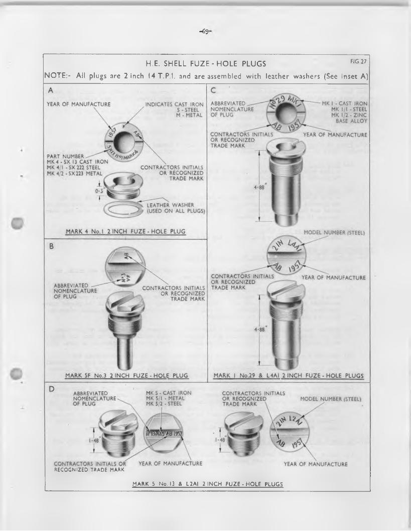
-69'
ABBREVIATED _ - NOMENCLATURE OF PLUG
MK I - CAST IRON MK l / l - STEEL MK 1/2 - ZINC
BASE ALLOY
YEAR OF MANUFACTURE INDICATES CAST IRON S - STEEL M - METAL
CONTRACTORS INITIALS OR RECOGNIZED ^ TRADE MARK
YEAR OF MANUFACTURE
PART NUMBER MK4 - SX 13 CAST IRON MK 4 I - SX 222 STEEL MK 4/2 - S X 223 METAL
CONTRACTORS INITIALS OR RECOGNIZED
\ TRADE MARK
LEATHER WASHER (USED ON ALL PLUGS)
M ARK 4 No. I 2 IN C H FU ZE - H O LE PLUG MODEL NUMBER (STEEL)
CONTRACTORS INITIALS OR RECOGNIZED TRADE MARK
YEAR OF MANUFACTUREABBREVIATED NOMENCLATURE OF PLUG
CONTRACTORS INITIALS OR RECOGNIZED
TRADE MARK
M ARK SF N o.3 2 IN C H FU ZE - H O LE PLUG M ARK I No.29 & L4AI 2 IN C H FU ZE - H O LE PLUGS
MK 5 - CAST IRON MK 5/1 - METAL MK 5 2 - STEEL
ABBREVIATED NOMENCLATURE OF PLUG
CONTRACTORS INITIALS OR RECOGNIZED TRADE MARK \
MODEL NUMBER (STEEL)
CONTRACTORS INITIALS OR YEAR OF MANUFACTURE YEAR OF MANUFACTURE
H.E. SHELL FU Z E-H O LE PLUGS FIG27NOTE:- All plugs are 2 inch I4T.P.I. and are assembled with leather washers (See inset A)
RECOGNIZED TRADE MARK
M ARK 5 No. 13 & L2A I 2 IN C H FU ZE • H O LE PLUGS
- 7 0 -
The fuze covers o f combustion time fuzes should be kept on u n til immediately before use and not removed when preparing fo r ready-use. Fuzes with tigh t covers should preferably be used fo r ready- use, the covers being tested fo r looseness by a straight pu ll only and never by a tw isting motion that might disturb the setting.
NATURES OF SI*ELL NORMALLY ISSUED HJZED OR PLUGGED2^4. Base fuzed, sh ell are issued with fuzes assembled, and fla re and star shell are normally issued
with fuzes assembled. Smoke shell previous to October 195& were issued with fuzes assembled, but a fte r th is date they are issued plugged.
■Q.F. 25 pr. H.E. shell are normally issued fuzed, except H.E. shell f i l l e d to code L7 (DD(L)18851 end D2(L)55A/GF/229) and those issued sp ec ifica lly fo r use with fuze No. 213.
M.L. 4.2 inch mortar bombs are normally issued fuzed.B.L. 4.5 inch and 5*5 inch gun and 7*2 inch howr. H.E. sh ell are issued plugged.
265. Types o f plugs used fo r H.E. shell - H.E. shell may be issued plugged with one o f three d iffe ren t types o f plug which vary according to the type o f f i l l i n g and method o f explodering i . e . : -
(a ) Plug No. 3 (F ig . 27B)A plug with a long shank. The head may be painted or otherwise coloured black or i t may be painted the same colour as the basic body colour o f the shell.
(b ) Plug No. 13 or L2A1 (F ig . 27D)A plug without a shank. The head is painted or lacquered blue to denote that the top exploder is assembled in position . The No. 13 may be manufactured o f s tee l, case iron or metal and must not be fir e d . The L2A1 is o f stee l and may be used in l ie u o f a fuze when the gun is required to be zeroed.
(c ) Plug No. 29 or L4A1 (F ig . 27C)Shell f i t t e d with th is plug have no top exploder and are fo r use with VT fuzes only.
INSTRUCTIONS FOR RJZING2 6 6 . To fuze H.E. sh e ll plugged with No. 13 or L2A1 plugs (F ig . 26,
(a ) Remove the plug and leather washer. Shell with plugs set fa s t should be set aside, no leverage other than the key provided must be used.
(b ) Remove the tracing cloth discs and examine the exposed portion o f the top exploder bag toensure that i t is in good condition. I f no top exploder is present, insert one asdescribed in para 267 (c ) and (d)o Replace the tracing clo th d iscs, w ith the glazed sidestogether, on top o f the exploder. I f only one tracing cloth disc is ava ilab le, place i t with i t s glazed side next to the exploder.
(c ) Inspect the fuze hole threads and the fuze cavity to ensure that there are no pa rtic les o f C.E. present. I f any pa rtic les are found no attempt should be made to fuze the sh e ll, which should be set aside fo r disposal as described fo r defective ammunition in para. 286.
(d ) See that the base and screw-threads o f the fuze are clean and that the threads are undamaged. The lower threads, except the innermost three, should then be l ig h t ly smeared with thin lu ting , and the upper threads with lu tin g , th ick , Mk. 8, a f i l l e t o f the la t te r being placed around the underside o f the flange.
(e ) Screw the fuze in to the sh e ll, using the correct key. Make certain that the fuze goesrigh t home, no forcing should be necessary. I f the fuze body binds againsc the cavityw a ll, re je c t the sh e ll or the fuze according to which is at fa u lt. Do not hammer on the fuze key handle to tighten the fuze. Use only such pressure as can be applied by hand to the fuze key handle. I f the fuze cannot be tightened so that a good seating is obtained between the l ip o f the shell and the flange o f the fuze, re je c t e ither the sh e ll or the fuze. Wipe o f f any excess o f lu ting which may exude at the shell/fuze jo in t .
267. To fuze H.E. shell plugged with No. 3 plugs, fo r use with percussion or time fuzes (F ig . 28)
(a ) Remove the plug and leather washer. Shell with plugs set fast should.be set aside, no leverage other than the key provided must be used.
(b ) Inspect the fuze-hole threads and the fuze cav ity to ensure that there are no pa rtic les o f C.E. or H.E. f i l l i n g present. I f any pa rtic les are found no attempt should be made to fuze the sh e ll, which should be set aside fo r disposal as described fo r defective ammunition in para.286.
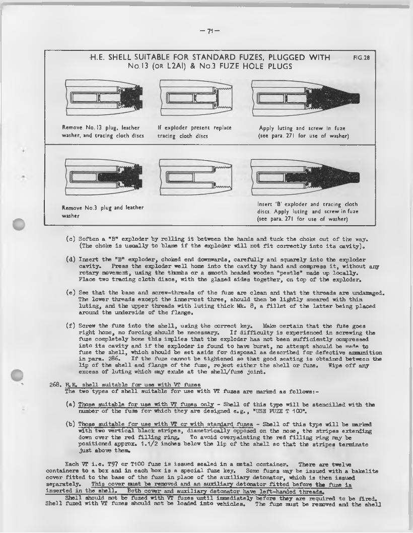
- 7 1 -
-H.E. SHELL SUITABLE FOR STANDARD FUZES, PLUGGED WITH f ig .28
No. 13 (OR L2AI) & No.3 FUZE HOLE PLUGS
Remove No. !3 plug, leather washer, and tracing cloth discs
If exploder present replace tracing cloth discs
Apply luting and screw in fuze (see para. 271 for use of washer)
Remove No.3 plug and leather washer
Insert ‘B’ exploder and tracing cloth discs. Apply luting and screw in fuze (see para. 271 for use of washer)
(c ) Soften a "B" exploder by ro ll in g i t between the hands and tuck the choke out o f the way.(The choke is usually to blame i f the exploder w i l l not f i t co rrectly in to i t s cavity ) 0
(d ) Insert the "B" exploder, choked end downwards, ca re fu lly and squarely in to the exploder cavity0 Press the exploder w ell home into the cavity by hand and compress i t , without any rotary movement, using the thumbs or a smooth headed wooden "pestle” made up lo ca lly .Place two tracing c lo th discs, with the glazed sides together, on top o f the exploder.
(e ) See that the base and screw-threads o f the fa ze are clean and that the threads are undamaged. The lower threads except the innermost three, should then be l i ^ i t l y smeared with thin lu ting , and the upper threads with lu ting th ick Mk. 8, a f i l l e t o f the la tte r being placed around the underside o f the flange.
( f ) Screw the fuze in to the sh e ll, using the correct key. Make certa in that the fa ze goes righ t home, no fo rc ing should be necessary. I f d i f f ic u lt y is experienced in screwing the fuze conpletely home th is imp lies that the exploder has not been su ffic ien tly compressed in to i t s cav ity and i f the exploder is found to have burst, no attenpt should be m«fte to fuze the sh e ll, which should be set aside fo r disposal as described fo r defective amnunition in para. 286. I f the fuse cannot be tightened so that good seating is obtained between the l ip o f the sh e ll and flange o f the fuze, re jec t e ith er the sh e ll or fuze. Wipe o f f any excess o f lu ting which may exude at the shell/fuze jo in t.
268. H.E. sh ell suitable fo r use with VT fuzesThe two types o f sh e ll suitable fo r use with "VT fuzes are marked as fo llow s: -
(a ) Those suitable fo r use with VT fuzes only - Shell o f th is type w i l l be s ten c illed with the number o f the fuze fo r which they are designed e .g . , "USE FUZE T 100".
(b ) Those suitable fo r use w ith VT or with standard fuzes - Shell o f th is type w i l l be marked with two v e r t ic a l black stripes, diam etrically opposed on the nose, the stripes extending down over the red f i l l i n g ring. To avoid oveipainting the red f i l l i n g ring may be positioned approx. 1 . 1/2 inches below the l ip o f the sh e ll so that the stripes terminate just above them.
Each VI i . e . T97 or T100 fuze is issued sealed in a metal container. There are twelve containers to a box and in each box is a special fuze key. Some fuzes may be issued with a bakelite cover f i t t e d to the base o f the fuze in place o f the auxiliary detonator, which is then issued separately. This cover must be removed and an auxiliary detonator f i t t e d before the fuze is inserted in the sh e ll. Both cover and auxilia ry detonator have left-handed threads.
Shell should not be fuzed with VT fuzes u n til inroediately before they are required to be fired . Shell fuzed with VT fuzes should not be loaded in to veh icles. The fuze mist be removed aixl the sh e ll
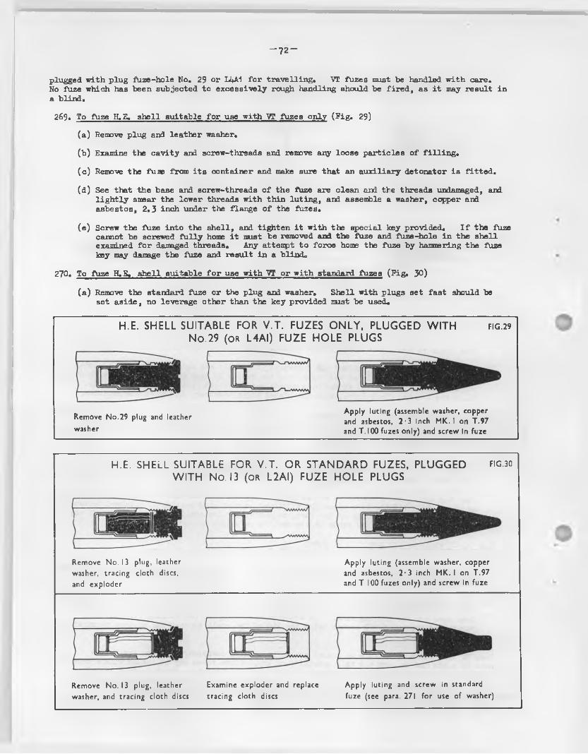
- 7 2 “
plugged with plug fuze-hole No, 29 or Li+A1 fo r tra ve llin g , VT fuzes must be handled w ith care.No fuze which has been subjected to excessively rough handling should be fire d , as i t may result in a blind.
269, To fuze H.E. sh ell suitable fo r use with ~VT fuzes only (F ig , 29)
(a ) Remove plug and leather washer,
(b ) Examine the cav ity and screw-threads and remove any loose pa rtic les o f f i l l in g .
(c ) Remove the fuas from i t s container and make sure that an auxilia ry detonator is f it te d .
(d ) See that the base and screw-threads o f the fuze are clean and the threads uiklamaged, and l ig h t ly smear the lower threads with thin lu ting, and assemble a washer, copper and asbestos, 2.3 inch under the flange o f the fuzes.
(e ) Screw the fuze in to the sh e ll, and tighten i t w ith the special key provided. I f the fuze cannot be screwed fu l ly home i t must be removed and the fuze and fuze-hole in the shell examined fo r damaged threads. Any atteupt to force home the fuze by hammering the fuze key may damage the fuze and resu lt in a blind,
270. To fuze H.B. sh e ll suitable fo r use with VT or w ith standard fuzes (F ig . 30)
(a ) Remove the standard fuze or the plug and washer. Shell with plugs set fast should be set aside, no leverage other than the key provided must be used.
H.E. SHELL SUITABLE FOR V.T. FUZES ONLY, PLUGGED W ITH f ig .29 No. 29 (OR L4AI) FUZE HOLE PLUGS
Remove No.29 plug and leather washer
Apply luting (assemble washer, copper and asbestos, 2-3 inch MK. I on T.97 and T.I00 fuzes only) and screw in fuze
H.E. SHELL SUITABLE FOR V.T. OR STANDARD FUZES, PLUGGED fig.30 W ITH No. 13 (o r L2AI) FUZE HOLE PLUGS
Remove No. i3 plug, leather Apply luting (assemble washer, copperwasher, tracing cloth discs, and asbestos, 2-3 inch MK. I on T.97and exploder and T. 100 fuzes only) and screw in fuze
Remove No. 13 plug, leather Examine exploder and replace washer, and tracing cloth discs tracing cloth discs
Apply luting and screw in standard fuze (see para. 271 for use of washer)
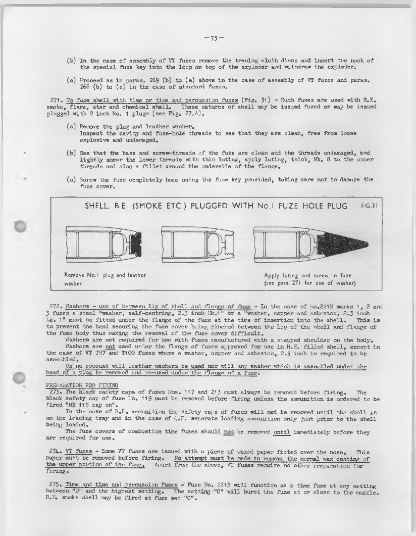
- 7 3 -
(b ) in the case o f assembly o f VT fuzes remove the tracing cloth discs and insert the hook o f the special fuze key into the loop on top o f the exploder and withdraw the expIcier.
(c ) Proceed as in paras. 269 (b ) to (e ) above in the case o f assembly o f VT fuzes and paras. 266 (b) to (e ) in the case o f standard fuzes.
271. To fuze sh ell with time or time and percussion fuzes (F ig . 31) - Such fuzes are used with 3.E. smoke, f la re , star and chemical sh e ll. These natures o f sh e ll may be issued fuzed or may be issued plugged with 2 inch No. 1 plugs (see F ig . 27.A ).
(a ) Remove the plug and leather washer.Inspect the cavity and fuze-hole threads to see that they are clean, free from loose explosive and undamaged.
(b ) See that the base and screw-threads o f the fuze are clean and the threads undamaged, and lig h t ly smear the lower threads with thin lu ting, apply lu ting, th ick, Mk. 8 to the upper threads and also a f i l l e t around the underside o f the flange.
(c ) Screw the fuse completely home U3ing the fuze key provided, taking care not to damage the fuze cover.
SHELL, B E. (SMOKE ETC.) PLUGGED W ITH No. I FUZE HOLE PLUG fig.3 i
Remove No.I plug and leather washer
Apply luting and screw in fuze (see para. 271 for use of washer)
272. Washers - use o f between l ip o f shell and flange o f fuze - In the case o f No.221B marks 1 ,2 and3 fuzes a stee l "washer, se lf-cen trin g , 2.3 inch Mk.1" or a "washer, copper and asbestos, 2.3 inchluk. 1" must be f it te d under the flange o f the fuze at the time o f insertion in to the sh e ll. This is to prevent the band securing the fuze cover being pinched between the l ip o f the shell and flange of the fuze body thus making the leraoval o f the fuze cover d i f f ic u lt .
'Washers are not required fo r use with fuzes manufactured with a stepped shoulder on the body.Washers are not used under the flange o f fuzes approved fo r use in H.S. filled , sh e ll, except in
the case o f VT T97 and T100 fuze3 where a washer, copper and asbestos, 2.3 inch is required to be assembled.
On no account w ill lea ther washers be used nor w ill any washer -which is assembled under the head o f a plug be removed and re-used under the flange o f a fuze.
PREPARATION FOR FIRING-273* The black safety caps o f fuzes Nos. 117 and 213 must always be removed before f i l in g . The
black sa fety cap o f fuze No. 119 must be removed before fir in g unless the ammunition is ordered to be fired "HE 119 cap on".
In the case o f B.L. ammunition the sa fety caps o f fuzes w i l l not be removed u n til the shell is on the loading tray and in the case o f Q.F. separate loading ammunition only just p rior to the shell being loaded.
The fuze covers o f combustion time fuzes should not be removed u n til immediately before they are required fo r use.
274. VT fuzes - Sane VT fuzes are issued with a piece o f waxed paper f i t t e d over the nose. This paper must be removed before f ir in g . No attenqrt must be made to remove the normal wax coating o f the upper portion o f the fuze. Apart from the above, VT fuzes require no other preparation fo r f ir in g .
275• Time and time and percussion fuzes - Fuze No. 221B w ill function as a time fuze at any setting between "0" and the highest se ttin g . The setting "0" w i l l burst the fuze at or close to the muzzle. E.E. smoke 3h e ll may be fired at fuze set "0 ".
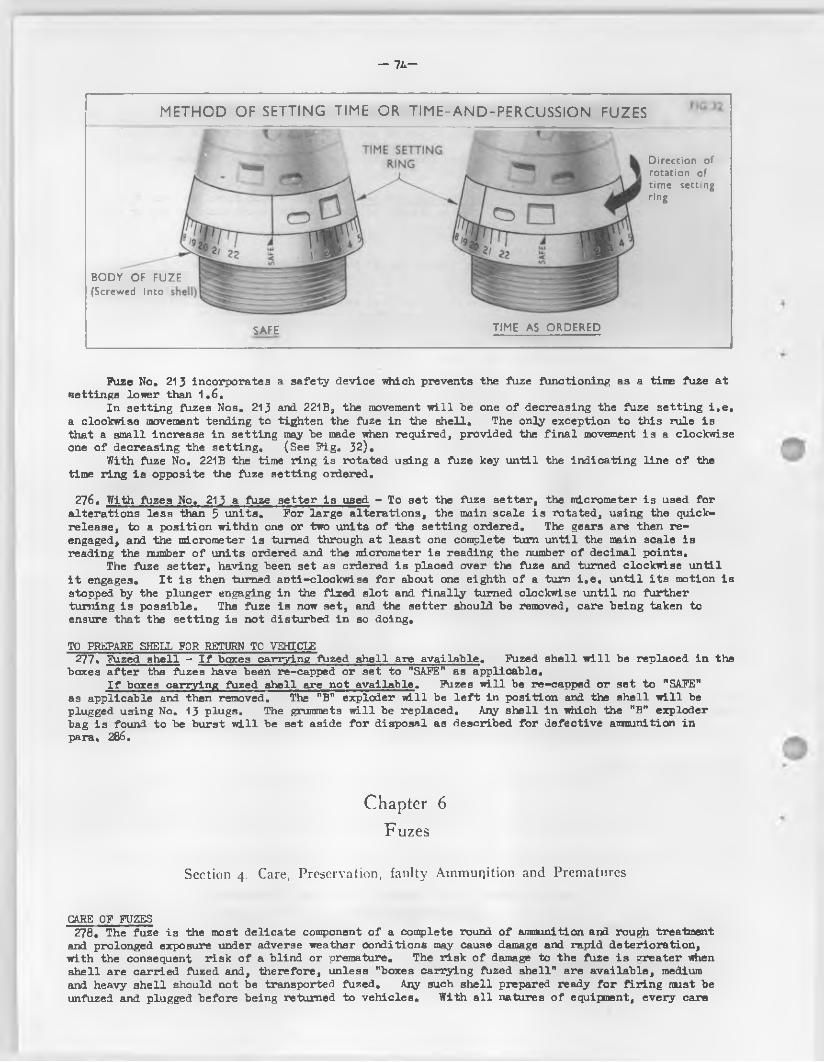
— 1L—
METHOD OF SETTING TIME OR TIME-AND-PERCUSSION FUZES
Direction of rotation of time setting ring
BODY OF FUZE (Screwed into
SAFE TIME AS O R D ER ED
Fuze No. 213 incorporates a safety device which prevents the fuze functioning as a time fuze at settings lower than 1 . 6.
In setting fuzes Nos. 213 and. 221B, the movement w i l l he one o f decreasing the fuze setting i . e . a clockwise movement tending to tighten the fuze in the shell. The only exception to this rule is that a small increase in setting may be made when required, provided the f in a l movement i s a clockwise one o f decreasing the setting. (See F ig . 32).
With fuze No. 221B the time ring is rotated using a fuze key u n til the ind icating lin e o f the time ring i s opposite the fuze setting ordered.
276. With fuzes No. 213 a fuze se tter i s used - To set the fuze se tte r , the micrometer is used fo r a lterations less than 5 units. For la rge a lterations, the main scale i s rotated, using the quick- release, to a position within one or two units o f the setting ordered. The gears are then reengaged, and the micrometer is turned through a t least one complete turn u n til the main scale is reading the number o f units ordered and the micrometer is reading the number o f decimal points.
The fuze setter, having been set as ordered i s placed over the fuze and turned clockwise u n til i t engages. I t i s then turned anti-clockwise fo r about one eighth o f a turn i . e . u n til i t s motion is stopped by the plunger engaging in the fixed s lo t and f in a lly turned clockwise u n til no further turning is possib le. The fuze is now set, and the setter should be removed, care being taken to ensure that the setting is not disturbed in so doing.
TO PREPARE SHELL FOR RETURN TO VEHICLE277. Fuzed sh e ll - I f boxes carrying fuzed sh e ll are ava ilab le. Fuzed sh e ll w i l l be replaced in the
boxes a fte r the fuzes have been re-capped or set to "SAFE" as applicable.I f boxes carrying fuzed shell are not ava ilab le. Fuzes w ill be re-capped or set to "SAFE"
as applicable and then removed. The "B" exploder w ill be l e f t in position and the sh e ll w i l l be plugged using No. 13 plugs. The grummets w i l l be replaced. Any sh e ll in which the "B" exploder bag i s found to be burst w i l l be set aside fo r disposal as described fo r defective ammunition in para. 286.
Chapter 6
Fuzes
Section 4. Care, Preservation, faulty Ammunition and Prematures
CARE OF FUZES278, The fuze is the most delicate component o f a complete round o f ammunition and rough treatment
and prolonged exposure under adverse weather conditions may cause damage and rapid deterioration , with the consequent r isk o f a blind or premature. The r isk o f damage to the fuze i s greater when sh ell are carried fuzed and, therefore, unless "boxes carrying fuzed shell" are ava ilab le, medium and heavy sh e ll should not be transported fuzed. Any such shell prepared ready fo r f ir in g must be unfuzed and plugged before being returned to veh icles. With a l l natures o f equipment, every care
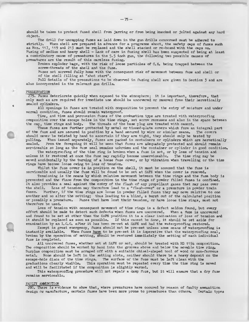
r— 75 —
*
should be taken to protect fuzed shell from jarring or from being knocked or jo lted against any hard object.
The d r i l l fo r uncapping fuzes as la id down in the gun d r i l ls concerned must be adhered to s t r ic t ly . When shell are prepared in advance fo r a programme shoot, the sa fety caps o f fuzes such as Nos. 117, 119 and 213 must be replaced and the sh e ll stacked or re-boxed with the caps on.Fuzing o f medium and heavy sh e ll Lack o f care in fuzing sh e ll has been suspected o f being at least a contributory cause o f prematures in the 5« 5 inch gun, the fo llow ing two possible causes o f prematures are the result o f th is care less fuzing.
Broken exploder bags, w ith the r isk o f loose pa rtic les o f C.E. being trapped between thescrew-threads o f the shell and the fuze.Fuzes not screwed fu lly home with the consequent r isk o f movement between fuze and sh ell oro f the shell f i l l i n g at "shot s ta rt".Full d e ta ils o f the precautions t o be observed in fuzing shell are given in Section 3 and are
also incorporated in the relevant gun d r i l ls .
PRESERVATION279* Fuzes deteriorate quickly when exposed to the atmosphere; i t is inportant, therefore, that
only such as are required fo r immediate use should be uncovered or removed from th e ir herm etically sealed cylinders.
A l l openings in fiz e s are treated with conposition to prevent the entry o f moisture and under normal condition, fuzes should remain waterproof.
Time, and time and percussion fuzes o f the combustion type are treated with waterproofing conposition over the escape holes in the time rings, set screw recesses and also in the space between the cap, time ring3 and body. The threads o f the base plug are treated w ith cement.
These fuzes are further protected by metal or tinned-plate covers which form an in tegra l part o f the fuze and are secured in position by a band secured by w ire or sim ilar means. The covers should never be twisted by hand to ascertain i f they are t ig h t, they should only be tested by pu lling. When issued separately, fuzes are packed in containers or cylinders which are hermetically sealed. From the fbregoing i t w i l l be seen that fuzes are adequately protected and should remain serviceable sc long as the fuze seal remains unbroken and the container or cylinder in good condition.
The waterproofing o f the time ring is broken when a fuze is set, or by loss o f tension and unless i t is restored at once the fuze may rap id ly become unserviceable. The time ring may be moved accidentally by the turning o f a loose fuze cover, or by v ib ration when tra ve llin g or the tit® rings have become loose owing to loss o f tension.
Whilst the fuze cover i s in position on the sh e ll, i t must be assumed that the fuze is serviceable and usually the fuze w i l l be found to be set at SAFE when the cover is removed#
Tensioning is the means by which re la tiv e movement between the time rings and the fuze body is prevented and the flame from the conposition in the time rings o f powder f i l l e d fuzes is confined.I t a lso provides a seal against the entry o f the fla sh o f any propellant gases that may pass over the shell. Loss o f tension may therefore lead to a "flash-over" or a premature in powder tra in fuzes. Further, i f the tine lings are loose in powder f i l l e d fuzes they may move re la tiv e to one another and so a lte r the settin g ; thus leading to a b lind , a burst out o f the calculated position or possib ly a premature. Fuzes that have lo s t th e ir tension, or have loose time rings, must not therefore be used.
Loss o f tension with consequent movement o f time rings is a defect seldom found, but every e f fo r t should be made to detect such defects when fazes are uncovered. When a f\ize is uncovered and found to be set at other than the SAFE position i t is a c lear indication o f loss o f tension and i t should be replaced as soon as possib le. I f th is cannot be done, i t should be set aside fo r examination by an 1 .0.0. a fte r i t lias been re-set at SAFE and had the waterproofing restored.
Except in great emergency, fuzes should not be pre-set unless some means o f waterproofing is instan tly availab le. When fuzes have to be pre-set i t is imperative that the waterproofing sea l, broken by the operation o f setting, should be restored inmediately the setting o f each individual fuze is completed.
A l l uncovered fuzes, whether set at SAFE or not, should be treated with ED 1134 conposition.The conposition should be worked by hand into the grooves above and below the movable time ring. Surplus conposition must be scraped o f f with a suitable chisel-shaped too l o f wood or non-ferrous metal. None should be l e f t in the setting s lo ts , neither should there be a heavy deposit on the escape-hole discs o f the tin® rings0 The surface o f the fuze must be l e f t clean with the graduations c lea r ly v is ib le . This operation must be repeated every tin® the time ring is moved and w i l l be fa c il ita te d i f the conposition is s lig h t ly warmed.
This waterproofing procedure w i l l not repair a damp fuze, but i t w i l l ensure that a dry fuze remains serviceable.
FAULTY AMMUNITION280. There is evidence to show that, where prematures have occured by reason o f fau lty ammunition
design or manufacture, certa in fuzes have been more prone to prematures than others. Certain types
-7 6 -
and marks o f fuzes are therefore res tr ic ted in th e ir use both fo r training and operations. This matter i s under constant review and Array Council Instructions are issued and amended from time to time to g ive the la te s t position . The provisions o f these A .C .I 's must be s t r ic t ly observed.
PREMATURES281 . Most o f the evidence is destroyed although circumstantial evidence w ill be ava ilab le by taking
d e ta ils o f the next round that would have been fire d but fo r the premature. Particu lars o f the sh e ll burst are most valuable. The nature o f the burst, including position , noise, appearance and the colour o f the smoke and the presence or absence o f strike marks on the ground should be noted.An immediate search should also be made fo r a l l shell and fuze fragments. Fragments should be retained fo r subsequent expert examination and a sketch made to show where they were recovered in re la tion to the gun.
Evidence o f actual fuze se ttin g , bearing and Q.E., are also most valuable and eveiy e ffo r t should be made to record even approximate d e ta ils .
Equipment damaged as a resu lt o f a premature, which in the opinion o f R.E.M.E., warrants further examination, w i l l be despatched to D .I. Arm. under arrangements to be made by D.D.O.S. Command.
282. Rates o f f i r e - The risk o f prematures from a l l causes w i l l r is e when a high rate o f f i r e is maintained fo r any considerable time. Except fo r very short bursts o f f i r e , a rate fa s te r than that la id down as "intense" fo r the equipment concerned should not be orderedo
283. Records o f prematures - Many t r ia ls have been carried out in order to prove or disprove suggested causes fo r prematures. Investigations are s t i l l continuing and inport ant information on the causes o f prematures can be provided i f Units render deta iled reports regarding any prematures suffered by then.
Full instructions as to the procedure to be adopted on the occurrence o f a premature and a specimen o f the form on which the relevant facts should be entered are contained in R.A.O.S.Volume I I I , Pamphlet No. 5> which i s issued on the scale o f one fo r each regiment.
DEFECTIVE FUZES284. Defective fuzes (as defined in the gun d r i l ls ) may cause blinds or prematures, th erefore:-
Before medium or heavy shell are fuzed, the fuzes should be inspected as described in the gund r i l l s and any fuze which is d e fective or which appears to have been damaged in any way w i l l be set aside, reported and must not be used fo r fuzing any sh e ll. With aramunition supplied fuzed, the fuzes should be inspected when preparing the ammunition and any shell with a de fective fuze or one which appears to have been damaged must be set aside, reported and not fir e d .
The fuze covers o f combustion time fuzes should be kept on u n til immediately before use and should not be removed when preparing fo r ready-use. Any fuzes which are found to be set at anything Other than "SAFE" when the cover is removed must be set aside and not fir e d . I t i s a lso important that fuzes should be screwed fu lly home in the sh ell and where fuzes such as combustion time fuzes are required to be secured by a fix in g screw, that the head o f the fix in g screw is screwed home below the surface o f the sh e ll w a ll. S im ilarly , washers i f f i t te d beneath the flange o f the fuze must be properly centred as any protrusion w i l l seriously a ffe c t b a ll is t ic s .
UNSERVICEABLE FUZES285. The fo llow ing ammunition should be treated as unserviceable and on no account should i t be
f ir e d , or replaced in vehicles
(a ) Fuzes Nos. 117* 119 and 213 with damaged or d e fic ien t s tr ik e r covers o r d iscs .
(b ) Shell fuzed with time or time and percussion fuzes which cannot be reset to "SAFE".
(c ) Shell fuzed VT fuzes which cannot be defuzod and plugged.
286. Disposal o f de fective amnunition - At p ractice , defective ammunition w i l l be set aside fo r examination by an 1,0 .0 . (R .A .O .C .).
During operations, de fective ammunition w i l l be dumped and c lea r ly marked.
- 7 7 -
Chapter 7
Tracers and Tracer - and - Igniters
Section i. General
INTRODUCTION287* The po licy o f providing p ro je c tiles with some v is ib le indication o f th e ir f l ig h t through the
a ir to assist observation by the gunner has developed considerably, and th is chapter gives the
fosition to-date. I t consists o f a device assembled in the base o f the p ro je c t ile to emit ligh t and usually smoke) to form a trace fo r a specified time to assist night and day observation.
288. Dark ign it ion - To obtain a delay in the ligh tin g up o f a tracer system so that the path o f the "tracer*' is not v is ib le u n til the p ro je c t ile is some distance frem the nuzzle, a priming layer o f S.F.G.12 powder may be pressed in on torn o f the ign ito ry f i l l i n g (see para.295;* This is termed "dark ign ition " 0 The object o f the "dark ign ition " is s -
(a ) to prevent the f i r e r being dazzled by the b r i l l ia n t flame emitted.
(b ) to reduce the p o s s ib ility o f the position o f the gun being pin-pointed by eneiry observation from a flank.
P ro je c t ile s f i t t e d with "dark ign ition " tracers or tracer-ign iters are id en tifia b le by special symbols s ten cilled on the body (see para. 335)o
CLASSIKECATICN289* Current tracers may be c la ss ified under three main heads, v i z . ,
(a ) Tracers, shell
(b ) Tracer and ign iters , shell
( c ) In tegra l tracers
290. Tracers, sh ell are separate components in tliat they are not in tegra l with the p ro je c t ile ; they are, however, invariably issued assembled with the p ro je c t ile .
291. Tracer and ign ite rs , sh e ll are also separate components issued assembled with the p ro je c t ile , but they have the dual function o f tracing the tra jec to ry o f the p ro je c t ile and o f i t s destruction at a given time a fte r f ir in g .
292. In tegral tracers consist o f compositions pressed d irec tly in to a cavity (o r ca v it ie s ) formed in the base o f the p ro je c t ile .
Chapter 7
Tracers and Tracer - and - Igniters
Section 2. Tracers, Shell
DESCRIPTION293* General assembly - Tracers, sh e ll are normally made o f s tee l or metal rod bored out to take a
composite f i l l i n g o f tracing and priming compositions. They may be designed fo r assembly inside or protrusion outside the base o f the p ro je c t ile and are accordingly knorn as internal or external tracers. (See KLg«33) •
294* Method o f securing tracer to p ro je c t ile (F ig .33) - The external contour o f d iffe ren t tracers varies considerably according to the type o f p ro je c t ile fo r which they are designed and th is determines to a great extent the method o f securing tracer to p ro je c t ile . Current methods o f securing a re :-
(a ) Tracer threaded externally to screw in to the base o f the p ro je c t ile . This method o f securing is employed in tra cer,sh e ll, Nos.1, i6 and 36.
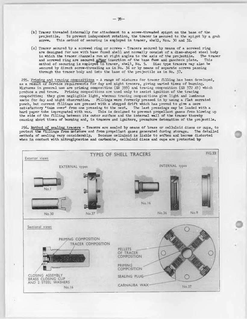
- 78 -
(b ) Tracer threaded in terna lly fo r attachment to a screw-threaded spigot on the base o f the p ro je c t ile . To prevent independent rotation , the tracer ia secured to the spigot by a grub screw. This method o f securing is enployed in tracer, sh e ll, Nos. 30 and 32o
(c ) Tracer secured by a screwed ring or screws - Tracers secured by means o f a screwed ring are designed fo r use with base fuzed shell and normally consist o f a disc-shaped stee l body in which the tracer channels run at r igh t angles to the axis o f the p ro je c t ile . The tracer and screwed r ing are secured a fte r insertion o f the base fuze and gascheck p la te . This method o f securing is employed in tracer, sh e ll, No. 9. Disc type tracers may also be secured by d irect screw-threading as in No. 36 or by means o f separate screws passing through the tracer body and into the base o f the p ro je c t ile as in No. 37.
295» Priming and tracing compositions - A range o f mixtures fo r tracer f i l l in g has been developed, as a result o f Service requirements fo r day and night tracers, g iv ing varied times o f burning.Mixtures in general use are priming composition (SR 399) and tracing composition (SR 372 AB) which produce a red trace. Priming conpositions are used only to assist ign ition o f the treeing conposition; they g ive n eg lig ib le l ig h t , whereas tracing conpositions give ligh t and luminous smoke fo r day and night observation. F ill in g s were formerly pressed in by using a f la t serrated punch, but current f i l l in g s are pressed with a stepped d r i f t which has proved to give a more sa tisfactory "take over” from one pressing to the next. The la s t pressings may be loaded w ith a hard paper tube impregnated with wax<> This is designed to prevent propellant gases from blowing up the side o f the f i l l i n g between i t s outer surface and the in ternal w all o f the tracer thereby causing short times o f burning and, in tracers and ign ite rs , premature detonation o f the p ro je c t ile .
296. Method o f sealing tracers - Tracers are sealed by means o f brass or c e llu lo id discs or cups, to protect the f i l l in g s from moisture and from propellant gases generated during storage. The deta iled methods o f sealing vary considerably. Because ce llu lo id is lia b le to soften and become distorted when in contact w ith n itroglycerine and carbamite, ce llu lo id discs and cups are protected by
1
TYPES OF SHELL TRACERSExterior views
INTERNAL typesEXTERNAL types
PRIMING COMPOSITIONTRACER COMPOSITION
PELLETS ----OF TRACER COMPOSITION
PRIMINGCOMPOSITION
CLOSING ASSEMBLY BRASS CLOSING CUP AN D 2 STEEL WASHERS
No. 16
SEALING PLUG
CARNAUBA W AX
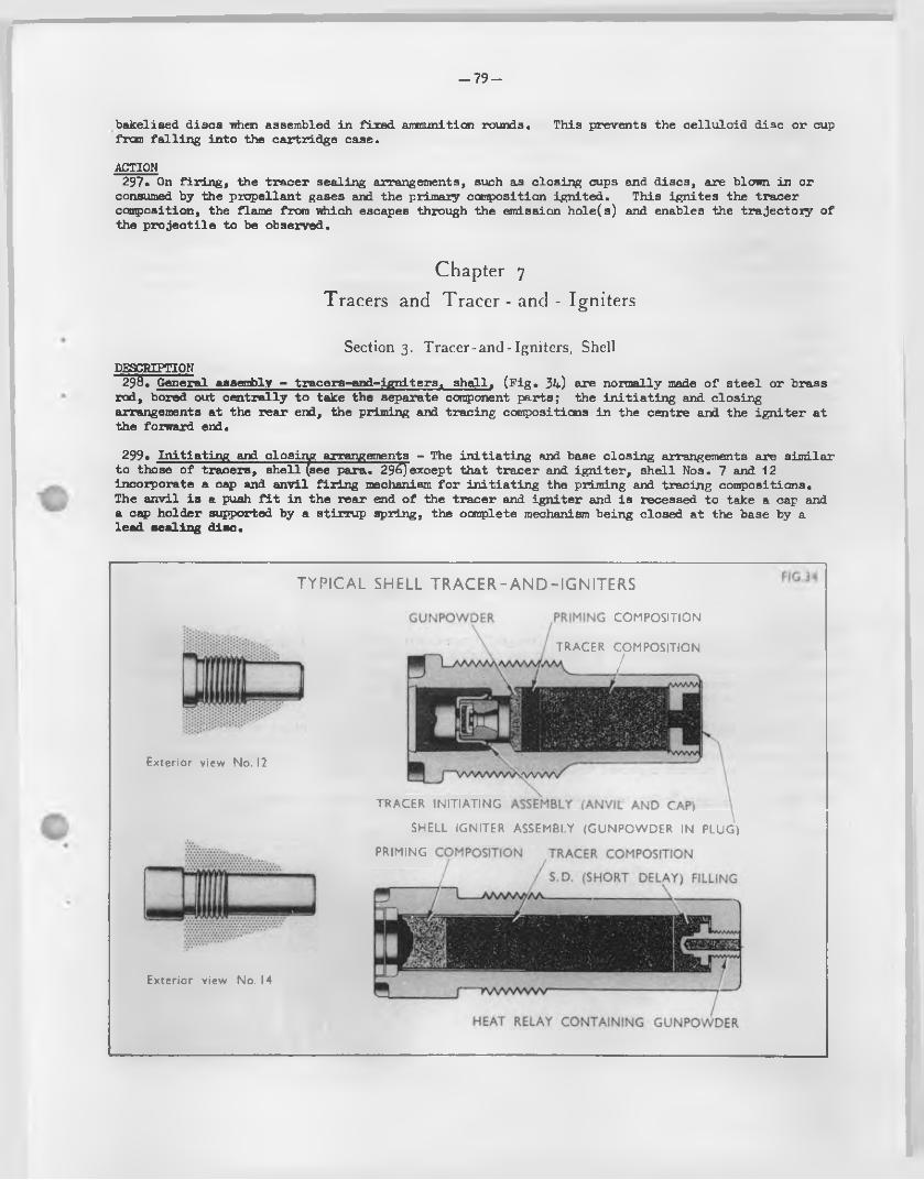
- 7 9 -
bakelised discs when assembled in fixed ammunition rounds. This prevents the ce llu lo id disc or cup from fa ll in g in to the cartridge case.
ACTION297« On f ir in g , the tracer sealing arrangements, such as closing cups and discs, are blown in or
consumed by the propellant gases and the primary composition ign ited . This ign ites the tracer conposition, the flame from which escapes through the emission hole (s ) and enables the tra jec to ry o f the p ro je c t ile to be observed.
Chapter 7
Tracers and Tracer - and - Igniters
Section 3. Tracer-and-Igniters, ShellDESCRIPTION
296. General assembly - tracers-and-igniters. sh e ll. (F ig . 34) are normally made o f s tee l or brass rod, bored out cen tra lly to take the separate component parts; the in it ia t in g and closing arrangements at the rear end, the priming and tracing compositions in the centre and the ig n ite r at the forward end.
299. In it ia t in g and olosiry; arrangements - The in it ia t in g and base closing arrangements are sim ilar to those o f tracers, shell (see para. 29^)except that tracer and ig n ite r , shell Nos. 7 and 12 incorporate a cap and anvil f ir in g mechanism fo r in it ia t in g the priming and tracing compositions.The anvil is a push f i t in the rear end o f the tracer and ign ite r and is recessed to take a cap and a cap holder supported by a stirrup spring, the complete mechanism being closed at the base by a lead sealing disc.
TYPICAL SHELL TR A CER -A N D -IG N ITERS
Exterior view No. I2
Exterior view No. 14
TRACER INITIATING ASSEMBLY (ANVIL AND CAP)
SHELL IGNITER ASSEMBLY (GUNPOWDER IN PLUG)
PRIMING COMPOSITION TRACER COMPOSITION
S.D. (SHORT DELAY) FILLING
f K W W W W
HEAT RELAY CONTAIN ING GUNPOWDER
COMPOSITION
TRACER COMPOSITION
. /
— 80—
300. Priming and tracing corrpositions - These are the same conpositions as used fo r tracers, sh ell (see para0 295)• In May, 1951, humidity controlled conditions were introduced in tracer f i l l i n gshops. Existing marks o f tracers and ign ite rs f i l l e d under the new conditions were a llo tted "/1" a fte r the mark, e .g :-
301. The ig n ite r - The ig n ite r consists o f a quantity o f gunpowder or S. R. composition lightly- pressed into the forward cavity o f the body or in to a screw-threaded plug (o r heat re la y ). The d ifference between a plug, as in tracer and ig n ite r , sh e ll, No. 12 and a heat re lay , as in tracer and ig n ite r , sh e ll, No. 14 is that the plug f i l l i n g is ign ited by d irect contact with the tracing composition, whereas the heat relay f i l l i n g is ign ited by conducted heat.
ACTION302. The action is sim ilar to that o f tracer, sh e ll described in para. 297 except fo r tracer and
ig n ite r , sh e ll, Nos. 7 and 12 in which an anvil and cap mechanism is usedo On f ir in g o f the la t te r the in e rt ia o f the cap and cap holder overcomes the resistance o f the stirrup spring and the cap is fir e d by the an vil. The flash from the cap ign ites the priming conposition which in turn ign ites the tracing composition. The resultant gases blow out the f ir in g mechanism and sealing d isc , thus perm itting the flame from the tracing conposition to be observed. A fte r a given time o fburning the tracing conposition ign ites the in it ia t in g conposition in the plug or heat relay to bring about detonation o f the p ro je c t ile .
DESCRIPTION303. Method o f f i l l i n g tracer cav it ies - In tegra l tracers are normally used only in so lid shot and
consist o f a number o f pressings o f tracing and priming conpositions f i l l e d d ire c t ly into one or more cav ities in the base o f the p ro je c t ile . (See P ig . 35)« Unlike other types o f tracers they are not a llo tted numbers and marks but may be id en tified by design, type, model or part number, stencilled on the body o f the projectile,,
304. Tracing compositions and size o f cavity - In February, 1943 i t was decided to adopt tracing conposition S.R.372 (red trace ) fo r a l l armour p iercing and practice shot. I t was a lso decided to adopt a standard cav ity diameter o f 0.435 inch fo r a l l shot o f 6 pr. to 3*7 inch ca libre (both inclusive). The current approved tracing conposition is now S.R.372 AB.
305. Method o f closing*- The method o f closing is s imila r to that used fo r tra ce r, shell.
Tracer and ig n ite r , No. 11, Mk. 3/1 Tracer and ig n ite r , No. 14, Mk. 2/1
Tracers and Tracer - and - Igniters
Section 4. Integral Tracers
TYPICAL INTEGRAL TRACER FILLINGS FOR SHOT FIG.3 5
CLOSING ASSEMBLY--------------CELLULOID CLOSING CUP AND PAPER DISC
TRACER COMPOSITION
PRIMING COMPOSITION
CLOSING A S S E f .BRASS CLOSING CUP AND 2 STEEL WASHERS
_ 81-
Chapter 8
Cartridges, Blank and Paper Shot
Section I. IntroductionGENERAL306. Blank ammunition - Blank cartridges consist o f a cartridge case and/or a cloth bag containing
only a charge, usually o f gunpowder although charges o f cordite have been approved fo r some equipments. They must not be fir e d with any form o f p ro je c t ile , and are provided so le ly fo r train ing, demonstration and saluting purposes.
A l l Q.F. blank cartridges have a red worsted clo th disc with the word "BLANK" printed thereon f i t t e d in the mouth o f the cartridge case. I t is shellacked to the outer surface o f the retain ing cup, i f such i3 positioned in the mouth o f the case or, where the cup is positioned w e ll down inside the case, the red disc is a ffix ed to the inside edge o f the mouth o f the case. The object o f th isdisc is to give a quick visual means o f ascertaining that the charge is actually present in the case and that i t has not been f ir e d and has not fa llen out in handling etc,
307, Paper shot cartridges - Special cartridges may be provided fo r use with paper shot. Such cartridges must not be fir e d with any other fo m o f p ro je c t ile . Paper shot cartridges and paper shot are normally provided fo r proof o f carriages and mountings to simulate f ir in g stresses.
To further assist id en tifica tion , Q.F. paper shot cartridges w i l l have in addition to the normal markings sten cilled on the base and side o f the cartridge case, a green paper disc shellacked to the outer surface o f the retain ing cup positioned in the mouth o f the case, or a lte rn a tive ly the outer surface o f the retaining cup may be painted lig h t green. The word "PAPER" is also c lea r ly printed on the disc or cup.
Chapter 8
Cartridges, Blank and Paper Shot
Section 2. Types authorised for Field Branch Artillery Equipments
CARTRIDGE BLANK (F ig . 36)308. Q.F, 23 pr,
Mark 1This is the normal charge and consists o f a marie 2 or /1 brass cartridge case f i t t e d with a
No. 1 percussion primer. The charge consists o f 1 lb . o f G. 12 gunpowder contained in a s ilk cloth bag. A leatherboard cup is inserted in the mouth o f the case, base downwards, and is wedged against the charge and secured with shellac.
Mark 2This is special fo r G ibraltar fo r saluting purposes only.I t d if fe rs from the marie 1 in that the charge consists o f 8 oz. o f G. 12 gunpowder contained in
a worsted cloth bag.These cartridges must never be used at a rapid rate o f f i r e .Mark 3This is special fo r Dover (except with Carriage Q.F. 25 pr*. saluting mark 1).I t d if fe rs from the marks 1 and 2 in that the charge consists o f 2 lb . o f G.12 gunpowder
contained in a s ilk cloth bag which is retained in the cartridge case by 3 leatherboard cups.These cartridges must never be used at a rapid rate o f f i r e .Mark 4This is the normal equivalent to the mark 1 cartridge.I t d iffe rs from the previous marks in having a charge o f 1 lb . 4 ozs. o f cord ite W.M. 017
which is retained in the cartridge case by one leatherboard cup. A No. 9 percussion primer is assembled in place o f the No. 1 primer.
309. B.L. 5«5 inch. 4.5 inch and 155 mm. gun.Mark 1This consists o f a charge o f 3 lb . o f G.12 gunpowder enclosed in a s ilk cloth bag, the
mouth o f the bag being choked and secured by s ilk thread,,
_ 8 2
310* B,L, 7 .2 inch Mark 1This consists o f a charge o f 7 lb , o f G.12 gunpowder enclosed in a s ilk cloth bag, the
mouth o f the bag being choked and secured by s ilk thread.
PRECAUTIONS TO BE OBSERVED WHEN FIRING BLANK AICIUNITION 311, When fir in g B,L, blank cartridges - No gun must be reloaded within 30 seconds a fte r f ir in g .
Even a fte r th is in terva l, no gun must be reloaded u n til the chamber and bore have been sponged out, examined and a l l debris removed. In the event o f a m isfire the normal m isfire d r i l l must be carried out except that, i f the tube has fired , a second tube must not be loaded but the detachment should immediately be ordered to stand clear, care being taken that no one is in the rear o f the breech and a pause o f not less than 30 minutes be allowed to elapse before the breech is opened.
When f ir in g Q,F, separate loading blank cartridges - In the event o f a m is fire the breech must not be opened fo r at least 30 minutes and no one must be in the rear o f the breech when i t i s opened.
CARTRIDGE PAPER SHOT 312. B,L, 5.5 inch Gun
There i s only one design i . e . , mark 1 consisting o f a charge o f 9 lb , A oz. cord ite WM, 109 f i l l e d to M, o f P , design DD(L)20296. This is in one portion which is f i t t e d with a single 1 oz, "C" gunpowder ig n ite r .
TYPES25 PR CARTRIDGE Q.F. BLANK MK.I
lib . Gunpowder G .I2 (M of F Design DD(L)9I96)
LE A T H ER B O A R D C L O S IN G CU P
G U N P O W D E R IN FA BRIC BAG IN C A R T R ID G E CASE
G U N P O W D E RG .I2
PRIMER RED
OF BLANK CARTRIDGES f i g .36
25 PR. C A R T R ID G E Q .F. B LA N K MK 4lib. 4oz. Cordite WM 0I7 (M of F Design D2(L)83I6 GF 246)
B U N D LED C O R D IT E IN C A R T R ID G E CASE
515 and 4 - 5 in. CARTRiDGE B.L, BLANK MK.I....... 3lb. Gunpowder G .I2 (M of F Design RL 404KI>)
-G U N P O W D E R G .I2
7 -2 in. C A R T R ID G E B.L. B LA N K MK.I 7 lb. Gunpowder G.I2 (M of F Design D2(L)306 GF I40)
G U N P O W D E R IN FA BR IC BAG G U N P O W D E R IN FA B R IC BAG
- 8 3 -
Chapter 9Drill Ammunition
Section 1. Introduction
GENERAL313* D r il l stores are provided fo r practising loading, handling and other d r i l l purposes. They
approximate to the shape and weight o f the Service store they represent and contain no explosive whatsoever.
Where d r i l l ammunition is made from the material used fo r the operational store, i t is painted black. Exceptions to th is ru le a re :-
(a ) Brass cases used in the assembly o f Q.F. d r i l l cartridges - such cases are not painted or otherwise coloured black; instead, they are l e f t in th e ir natural colour but the word DRILL i s stamped on the base o f the case,
(b ) D r i l l cartridges or charges made up in the same colour and cloth material as the operational store. These have the word DRILL sten cilled in black in a prominent position on each portion,
(c ) D r i l l stores made from material other than that used fo r the operational store, e . g . , wood, rubber, leather, e tc . , which are l e f t in th e ir natural sta te .
Any item o f d r i l l ammunition not marked or painted as described in the follow ing paragraphs must be returned to the R.A.O.C. and not used.
L ive ammunition, practice as w ell as operational, must not, in any circumstances, be used fo r d r i l l purposes.
A ll preliminary training is carried out with d r i l l ammunition and in peace-time no other nature o f ammunition should be on the gun position at the same time. In war, however, although d r i l l ammunition i s used fo r tra in ing, operational ammunition may also be on the gun position . This introduces a risk o f error and accident which can only be avoided by very carefu l attention on the part o f a l l concerned. The broad general ru le to fo llow at operational positions or elsewhere when operational ammunition i s present is to store the d r i l l ammunition in some central place c lea r o f the guns. I t should be brought to the gun position fo r train ing only, a l l l i v e ammunition being segregated and steps taken to ensure that the two types do not get mixed up during d r i l l . On completion o f the training period, the d r i l l ammunition should be returned to the central store, a l l items ca re fu lly checked and l i v e ammunition excluded.
Chapter 9 Drill Ammunition
Section 2. Components
DRILL CARTRIDGES 314. Q.F. 25 pr.
Mark 1This consists o f a mark 1 stee l d r i l l cartridge case. The charge represents the 1 lb . 11 oz.
4 dr. service charge. Shellacked twine represents the cord ite which i s enclosed in leather bags coloured red, white and blue and weighing 6 oz. 5 dr., 7 oz. 12 dr. and 13 oz. 3 d r. respectively .The portions are retained in position by a l id , leather, mark 1 ,
Mark 3 (use extended to apparatus, practising, loading)This d iffe rs from the Mark 1 in using a service mark 2 brass cartridge case and in the charge
being enclosed in coloured cloth bags in lieu o f leather also the rim o f the case is m illed .The words 25 p r. Mk. 3 DRILL are stanped on the base.
8 k ~
IJark 3/1 (a lso fo r use with apparatus, practising, loading)This d if fe rs from the mark 3 in the use o f a mark 5 s tee l cartridge cs.se, the rim o f which is
m illed .
The v.-oris 25 PR. MK.3/1 DRILL are stamped on the base.
315* B.L. 4.5 inch9 lb , 2 oz. mark 1 9 lb . 2 oz. mark 2Cloth; th ird charge; representating a second charge o f 6 lb . 7 02. and additional 2 lb . 11 oz.
portion tied together.
2 lb . 15 o z . mark 1 2 lb . 15 02. mark 2 Cloth; f i r s t charge.These are made up to represent the Service cartridges. Each portion consists o f a ro lled paper
cylinder, closed at each end with a wood plug and contained in a cloth bag provided with four lengths o f braid sewn to a cloth strengthening band at the base.
The 6 lb . 7 oz. bag is closed at the mouth with a dummy ig n ite r , the 2 lb . 11 oz. being closed at the mouth by a c lo th d isc.
The cartridge is brought to weight by being f i l l e d with sawdust and lead or iron scrap.The word DRILL is s ten c illed on the side o f each portion also on the ig n ite r and closing d isc .
The words "CHARGE THREE” sire marked on the side o f the assembled cartridge.The base o f the 6 lb . 7 oz. portion bag is also marked ”W0” and that o f the 2 lb . 11 oz.
portion "NOT TO BE FIRED SEPARATELY” .The 2 lb . 15 oz. cartridge consists o f a ro lled paper cylinder, closed at each end with a wood
plug, surrounded at the ig n ite r end with a short ro lled paper cylinder and contained in a c lo th bag closed at the mouth by a dummy ig n ite r .
The cartridge is brought to weight by being f i l le d with sawdust and lead or iron scrap.The word "DRILL" is s ten cilled on the side o f the cartridge head and on the ign ite r , the words
"CHARGE ONE" being marked on the stem.The mark 2 cartridges d i f f e r from the mark 1 in the bags being made o f cotton in lie u o f s ilk
cloth .
10 lb . 9 QZo mark 1Cotton c loth ; th ird charge; representing a second charge o f 7 lb . 9 oz. and an additional
3 lb . 0 oz. portion t ied together.
3 lb . 1 oz. mark 1Cotton cloth ; f i r s t charge.These consist o f cotton cloth bags, loaded to weight with rope and lead or iron scrap. The
dunrny ign ite rs consist o f two cotton cloth d iscs, sewn together and f i l l e d with scrap t e x t i le m aterial. The ends o f the cartridges are s tiffen ed with millboard discs.
The 10 lb . 9 oz. cartridge is in two portions, one 7 lb . 9 oz. and an increment o f 3 lb . .The 7 lb . 9 oz. portion has a dummy ig n ite r sewn to each end. The ends o f the 3 lb . portion are closed with cotton cloth discs.
The 3 lb . 1 oz. cartridge consists o f one bag with a dummy ign ite r sewn to each end.The 10 lb . 9 oz. cartridge has the la rge portion marked "CHARGE" on the side and "TWO" on the
end. The small portion has "THREE" on the side and the instruction "NOT TO BE FIRED SEPARATELY" on the end. When the two portions are tied together the ends are hidden and "CHARGE THREE" is shown.
The 3 lb . 1 oz. cartridge is marked "CHARGE ONE".
316. B.L. 5.5 inch9 lb . 2 oz. mark 1Cotton c loth ; charge four; representing charge three o f 6 lb . 10 oz. 8 dr and an increment
o f 2 lb . 7 oz. 8 d r. t ied together.
4 lb . k o z , mark 1Cotton c loth ; charge two; representing charge one o f 2 lb . 10 oz. 8 dr. and an increment of
1 lb . 9 oz. 8 dr. tied together.These are made up to represent the Service cartridges. The 9 lb . 2 oz. cartridge consists
o f two portions. Each portion consists o f a ro lled paper cylinder, closed at each end with a wood plug and contained in a cotton cloth bag provided with four lengths o f webbing sewn to strengthening bands at the base
- 8 5 -
The 6 In . 10 oh. 3 dr. bag is closed at the mouth with a dummy ign ite r and the 2 lb . 7 02. 8 dr. bag is closed at the mouth by a cotton cloth closing disc.
The portions are brought to weight by being f i l l e d completely with sawdust and lead or ironscrap.
The v/ord DRILL is s ten cilled on the side o f each portion, a lso on the ig n ite r and closing d isc. The words "CHARGE FOUR" are marked on the side o f the assembled cartridge, the la rger portion bearing the word "CHARGE" and the smaller portion the word "FOUR". The base o f the la rger bag is marked "THREE" and that o f the smaller bag "NOT TO 3E FIRED SEPARATELY", these base markings are hidden when the two portions are assembled.
The 4 lb . 4 oz. cartridge consists o f the two portions. The 2 lb . 10 oz. 8 dr. portion consists o f a ro lled paper cylinder, closed at each end by a wood plug, surrounded at the ig n ite r end with a short ro lled paper cylinder and contained in a cotton cloth bag closed at the mouth by a dunmy ig n ite r . I t is brought to weight by being f i l l e d completely with sawdust and lead or iron scrap.
The 1 lb . 9 os. 8 dr. increment consists o f a bundle o f 7.1/4 inch lengths o f 1 inch rope weighted v/ith lead sticks and enclosed in a cotton cloth bag closed at the mouth by thread stitch ing . The increment is secured to the stalk o f the la rge portion by two webbing tapes. The words "CHARGE TWO" are s ten cilled on the side o f the assembled cartridge, the la rger portion bearing the word "CHARGE" and the smaller portion the word "T 0". The stalk o f the la rger bag is marked "ONE", th is marking being hidden when the portions are assembled.
4 lb . 12 oz, mark 1Cotton cloth ; charge two; representing charge one o f 2 lb . 15 oz. and an increment o f 1 lb .
13 oz. t ied together.
9 lb . 13 oz. mark 1Cotton cloth; charge four; representing charge three o f 7 lb . 3 oz. and an increment o f 2 lb .
10 oz. t ied together.
12 lb . 9 oz. mark 1Cotton cloth ; fu l l charge; fo r 80 lb . sh e ll.These are made up to represent the Service cartridges.They consist o f cotton cloth bags, loaded to weight with rope and lead or ii'on scrap. The
dummy ign iters consist o f two cotton cloth discs sewn together and f i l l e d with scrap t e x t i le m aterial. The ends o f the cartridges are s tiffen ed with millboard discs.
The 4 lb . 12 o~. cartridge is in two portions, one 2 lb . 15 oz. and an increment o f 1 lb . 13 oz. The former has an ig n ite r sewn to each end while the ends o f the la t t e r are closed with cotton cloth discs.
The 9 lb . 13 oz. cartridge is also in two portions, one 7 lb . 3 oz. and an increment o f 2 lb .10 oz. The former has an ig n ite r sewn to each end vdiile the ends o f the la t te r are closed with cotton cloth d iscs.
The 12 lb . 9 oz. cartridge consists o f a bag with a duimy ig n ite r sewn to each end.The 4 lb . 12 oz. cartridge has the large portion marked "CHARGE" on the side and "ONE" on the
end. The small portion has "TWO" on the side and the instruction "NOT TO BE FIRED SEPARATELY" on the end. When the two portions are tied together the ends are hidden and "CHARGE TWO" is shown.
When the 9 lb . 13 oz. cartridge, which is sim ilarly marked, is assembled the "THREE" is hidden and"CHARGE FOUR" is shown.
The 12 lb . 9 oz. cartridge is maxked with a black band and the words "FOR 80 lb . SHELL ONLY".
317. B.L. 7.2 inchlb , 3 02. 8 dr. mark 1
Cotton cloth ; charge three, core and two sections.
25 lb . mark 1Cotton cloth ; charge four.These are made up to represent the Service cartridges.The 16 lb . 2 oz. 8 d r. cartridge consists o f a core and three sections o f the fo llow ing weights:-
core (section No.1) 6 lb . 11 oz ., section No. 2, 2 lb . 3 oz. 8dr. section No. 3* 7 lb . 5 oz.The core and sections, which are b u ilt up o f sawdust with lead or iron scrap, are each enclosed
in a cotton cloth bag being f it te d with a d r i l l ig n ite r consisting o f a f e l t disc and red cotton cloth discs with rows o f stitch ing.
The sections are assembled and tied with th e ir tapes around the stalk o f the core, section No.2 at the base end. Tapes from the core are threaded through fa irleads on the sections and tied on top o f No.3 sections.
The 25 lb . cartridge consists o f sawdust brought to weight with lead or iron scrap, contained in a cotton cloth bag choked at the mouth with thread and having a d r i l l ign ite r incorporated at the opposite end.
7 lb . mark 1Cotton cloth ; charge f iv e increment; fo r use with charge four in mark 6 howr. only.
13 lb . 11 oz. mark 1Cotton cloth; charge three; consisting o f charge one and two increments tied together.
24 lb . mark 1Cotton cloth ; charge four.These consist o f cotton cloth bags loaded with rope and lead or iron scrap. The dumny ign iters
consist o f two cotton discs sewn together and f i l l e d with scrap t e x t i le m aterial. The ends o f thecartridges are s tiffen ed with millboard discs.
The 7 lb . cartridge consists o f a bag with a dummy ign ite r sewn to each end.The 13 lb . 11 oz. cartridge consists o f charge one o f 6 lb . 10 oz. 8 d r. with two increment
charges o f 2 lb . 2 oz. and 4 lb . 14 oz. 8 dr. tied together with str ips o f webbing sewn to each charge. The 6 lb . 10 oz. 8 dr. portion has a dummy ig n ite r sewn to the outer end.
The 24 lb . cartridge consists o f bag with dummy ig n ite r sewn to each end.In addition to the usual marking, the word DRILL and charge number is s ten cilled on each
cartridge.
DRILL PROJECTILES318. Q.F. pr.
Shell mark 1The shell consists o f a hardwood body into which is f i t te d a mild s tee l central bo lt with lead
weight cast on, a brass nose and base and a detachable s tee l cap.The nose is screwed on to the top o f the central b o lt and secured to the body with a s tee l pin.
A s tee l cap having a knurled band screws on to the head. The base is screwed on to the bottom end o f the central bo lt and secured by r iv e tin g . Weight 21 lb .
The words 25 PR DRILL I are stamped on the side.
Shell mark 2This d if fe rs from the mark 1 in having a rubber body, the rubber being vulcanised on between
the brass nose and base, to the core which consists o f 12 lead weights held in position at the head by a brass plug and at the base by a hard rubber plug secured by a brass ring.
Weight 16 lb . 10 oz.The word DRILL is stencilled in white just above the shoulder.
Shell marie 3For use with apparatus, practising loading.This consists o f a modified stee l mark 1 H.E. streamline shell with the driving band turned
down and f it te d at the nose with a s tee l or cast iron plug to represent the fuze.Weight 16 lb . 1C oz.The words DRILL 25 PR. MK.3 SX1A are stamped on the base. The shell is painted black and
25 PR. MK. 3 DRILL i s s ten cilled above the shoulder.
Shot, mark 1This i s so lid , o f cast iron, and covered with waterproof canvas except fo r the nose and base.
Weight 15 lb . 7 oz•The words DRILL 25 PR. I are stamped on the base.
319. B.L. 4.5 inch streamline Shell marie 1This consists o f a rubber body on which 12 lead weights are f i t t e d , a brass nose, mild steel
base and detachable cap.The rubber body is vulcanised on between the nose and base and the weights held in position at
the head by a brass plug and at the base by a hard rubber plug secured by a s tee l r in g .Weight 430/4 lb .The word DRILL is stamped on the base and also sten cilled on the body just above the shoulder.
- 87 -
Shell mark 2The shell consists o f a hardwood body, cen tra lly bored and recessed to accornnodate a lead weight
cast on a central stee l tube which i s screw-threaded externally at each end fo r fix in g the nose and* base* A stee l plug f it te d with a detachable cap is screwed in to the nose* A brass c o lla r is secured round the body by six screws*
The words DRILL is stamped on the base and also stencilled in white above the brass co llar*
320. B*L* 5*3 inch streamlineShell mark 1This consists o f a rubber body, lead weights, a base and head o f mild s te e l, and a brass nose
f it te d with a screwed detachable cap o f s te e l.The body is vulcanised on to the head and base pieces and 11 lead weights are inserted in to the
bore o f the sh e ll. The weights are situated between the brass nose, which screws into the head, and a s tee l disc with a hard rubber plug f it te d in to the base. The brass nose is secured by a fix in g screw and the disc and plug by a stee l rin g . S teel discs may be inserted at one end o f the bore to prevent movement o f the weights. Weight (without stee l cap) 68.3/4 lb .
The words DRILL 5*5 I are stamped on the base.
Shell mark 2This represents the 80 lb . and 100 lb . sh e ll.I t consists o f a hardwood body, cen tra lly bored and recessed to accommodate a lead weight cast
on a central s tee l tube which i s screw-threaded externally at each end fo r fix in g the nose and base.A stee l plug f it te d with a detachable cap is screwed in to the nose. A brass co lla r is secured round the body by six screws.
The word DRILL i s stamped on the base and also sten cilled in white above the brass co lla r .
Shell, L4, mark 1For apparatus, practising loading, B.L. 5.5 inch guns, mark 1 .I t comprises a body and a nose plug. The body is that o f the mark 3 streamline H.E. shell
modified by le v e llin g the driving band to the diameter o f the shell and cutting a square shoulder 22.15 inches from the nose end to a diameter o f 5 inches.
The shell is painted black a l l over and marked 5.5 G MK. I DRILL L4 Mk. I on the base and side.
321. B.L. 7.2 inch streamlineShell mark 1The shell consists o f a hardwood body, nose plug and four segments. The segments are screwed
to the body and plug and a s tee l p la te i s screwed to the base. The whole is covered by rawhide stretched on to the sh ell and laced. Copper tacks further secure the rawhide near the top and base.
The mark and words 7.2 IN. DRILL are stamped on the side.
DRILL FUZES322. Id en tifica tion - These may be o f new manufacture or adapted from Service fuzes by emptying
or burning exit the explosive elements.A ll d r i l l fuzes are coloured black with the exception o f the graduated portion and setting
index o f time fuzes.Percussion fuzes, where practicable, are bored right through from nose to base and horizon ta lly
through the body.Time and percussion fuzes, where practicable, are bored horizon ta lly through the cap and
v e r t ic a lly from the base to the horizontal boring.
(a ) Stampings - Fuze number and markThe word DRILL is normally stamped on the fuze body in la rge type.The fuze number, mark and the word DRILL are f i l l e d in with white paint.
(b ) S tencillingThis is in white where used in lieu o f stamping.
DRILL PRIMERS323* Iden tifica tion - These may be o f new manufacture or made from converted fire d primers. A hard
rubber plug is inserted in the percussion cap recess in the base. The body o f the nrimer is blackened a l l over.
StampingsThe" word DRILL in large type )Number and mark are stamped on the baseManufacturers in it ia ls or trade mark )

-88-
DRILL TUBES* S.A.* PERCUSSION324. Id en tifica tion - Three elongated indents equally spaced are formed around the case and f i l l e d in
with red paint, the remainder o f the case being blackened a l l over*The anvil is also removed from the cap chamber.
StampingsManufacturers in i t ia ls or trade mark Mark o f tube
are stamped on the base
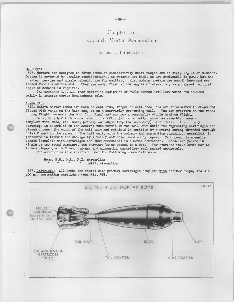
- 8 9 -
Chapter io
4.2 inch Mortar Ammunition
Section 1. Introduction
EQUIPMENT325* Mortars are designed to throw bombs at comparatively short ranges and at steep angles o f descent.
Design is governed by sim ilar considerations, as regards set-back, as are applicable to guns, but the chamber pressure and muzzle ve lo c ity are fa r smaller. Most modern mortars are smooth bore and are loaded from the muzzle end. They are never fir e d at low angles o f elevation , as an almost v e r t ic a l angle o f descent is required.
The ordnance M.L. 4*2 inch mortar is equipment o f F ie ld Branch A r t i l le r y units and is used mainly in counter mortar bombardment ro le .
AMMUNITION326). Modem mortar bombs are made o f cast iron , forged or cast s tee l and are streamlined in shape and
f i t t e d with vanes on the base end, or on a rearwardly projecting t a i l . The a ir pressure on the vanes during f l ig h t prevents the bomb "toppling" and ensures a reasonably stable head-on f l ig h t .
S.B., MJj. 4.2 inch mortar ammunition (F ig . 37) is normally issued as assembled rounds complete with fuze, t a i l unit, primary and augmenting (o r secondary) cartridges. The primary cartridge is assembled in the central tube formed in the t a i l unit while the augmenting cartridges are placed between the vanes o f the t a i l unit and retained in position by a sp iral spring threaded through holes formed in the vanes. The t a i l unit, with the primary and augmenting cartridges assembled, is protected in transit and storage by a waterproof cover secured by tapes. Each round is normally packed (complete with cartridges and fuze assembled) in a metal container. These are packed in single or two round carriers, two carriers being packed in a box. For overseas issue bombs may be issued plugged, with fuzes, primary and augmenting cartridges each packed separately.
The ammunition is c la ss ified under the fo llow ing nomenclatures: -
Bomb, S.B., M.L., H.E. streamline" " ** " d r i l l , streamline
327* Cartridges- A l l bombs are f i t t e d with primary cartridges complete with s tr ik er c lip s , and s ix 450 g r . augmenting cartridges (see F ig . 38)*
S B. M.L. 4 2 in MORTAR BOMB F IG .37
PRIMARY
housed in centre of TA IL U N IT
SIX A U G M EN TIN G C A R TR ID G ES
450 grn. TA IL ADAPTER NOSE ADAPTER
FU ZE
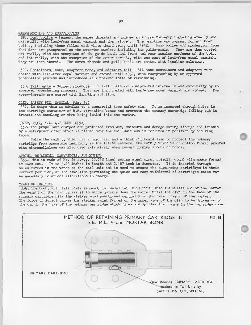
- 9 0 -
V/ATFKPRQOFING AND RUSTPROOFING32b. Bomb bodies - (except the screw threads) and guide-bands were formerly coated in terna lly and
externally with lead-free copal varnish and then stoved. The practice was current fo r a l l bomb bodies, including those f i l l e d with white phosphorus, u n til 1952. Bomb bodies o f f production from that date are phosphated on the ex terio r surface including the guide-bands. They are then coated externally , with the exception o f the guide-bands and front and rear annular surfaces o f the body, and in terna lly , with the exception o f the screw-threads, with one coat o f lead -free copal varnish.They are then stoved. The screw-threads and guide-bands are coated with lanoline solution.
329. Containers, nose, adapters nose, and adapters t a i l - A l l nose containers and adapters were coated with lead -free copal varnish and stoved u n til 1952, when m stproofing by an approved phosphating process was introduced as a pre-requ isite o f varnishing.
33° • T a il units - Current production, o f t a i l units are rustprdofed in terna lly and externally by an approved phosphating process. They are then coated with lead -free copal vam i3h and stoved. The screw-threads are coated with lanoline solution.
CLIP, SAFETY PIN, SPECIAL (F ig . 38)331. In shape th is is sim ilar to a commercial type safety pin . I t is inserted through holes in
the cartridge container o f H.E. streamline bombs and prevents the primary cartridge fa ll in g out in transit and handling or when being loaded into the rnortar.
COVER, TAIL, M.L. A .2 II-iCK AD5TAR332. The propellant cliarges are protected from wet, moisture and damage during storage and transit
by a waterproof carer wiiich is placed over the t a i l unit and is retained in position by securing tapes.
While the mark 5, which has a hard base and a thick millboard disc to protect the primary cartridge from premature ign ition , is the la te s t pattern, the mark 3 which is o f cotton fabric proofed with n itroce llu lose was also used extensively when reconditioning stocks o f bombs.
SPRING, RETAINING. CARTRIDGES. AUGMENTING333'.' This is made o f No. 2£> s.w .g. (0.018 inch) spring steel w ire, sp ira lly wound with hooks formed
at each end. I t is 5*25 inches in length and 0.187 inch in diameter. I t is inserted through holes formed in the vanes o f the t a i l unit and is used to secure the augmenting cartridges in th e ir correct position , at the same time permitting the quick and easy withdrawal o f cartridges which may be necessary to e f fe c t a lterations in charge.
MEANS OF IGNITION334* The bomb, with t a i l cover removed, is loaded t a i l unit f i r s t in to the muzzle end o f the mortar.
The weight o f the bomb causes i t to s lid e quickly down the barrel u n til the c lip on the base o f the primary cartridge h its the s tr ik er stud positioned cen tra lly in the breech piece o f the mortar.The force o f impact causes the s tr ik e r point formed on the inner side o f the c l ip to be driven on to the cap in the base o f the primary cartridge which f ir e s and ign ites the charge in the cartridge case.
METHOD OF RETAINING PRIMARY CARTRIDGE IN S.B. M.L. 4*2in. MORTAR BOMB
FIG . 38
PRIM ARY C A R T R ID G E
jew showing PRIM ARY C A R T R ID G E ^'■ ‘•fetained in Tail U nit by
SA FETY PIN C U P , SPECIAL.
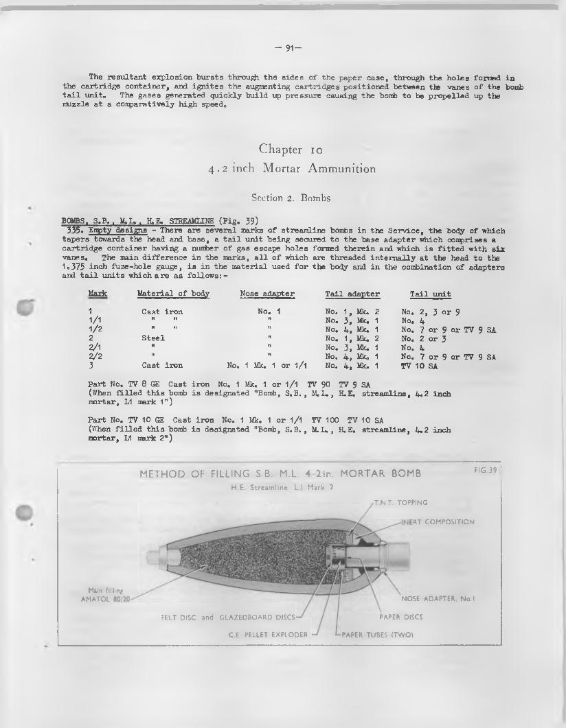
- 91 -
The resultant explosion bursts throu^i the sides o f the paper case, through the holes formed in the cartridge container, and ign ites the augmenting cartridges positioned between the vanes o f the bomb t a i l unite The gases generated quickly build up pressure causing the bomb to be propelled up the muzzle at a conparatively high speedo
Chapter io
4.2 inch Mortar Ammunition
Section 2. Bombs
BOMBS. S .B .. M.L.. H.E. STREAMLINE (P ig . 39)335» Empty designs - There are several marks o f streamline bombs in the Service, the body o f which
tapers towards the head and base, a t a i l unit being secured to the base adapter which conprises a cartridge container having a number o f gas escape holes formed therein arxl which is f i t t e d with six vanes. The main d ifference in the marks, a l l o f which are threaded in tern a lly at the head to the1.375 inch fuze-hole gauge, is in the material used fo r the body and in the combination o f adapters and t a i l units which a re as fo llow s:-
Mark Material o f body Nose adapter T a il adapter T a il unit
1 Cast iron No. 1 No. 1, Mk. 2 No. 2, 3 or 91/1 11 11 t! No. 3, Mk. 1 No. 41/2 11 i i II No. 4 , Mk. 1 No. 7 or 9 or TV 9 SA2 Steel it No. 1, Mk. 2 No. 2 or 32/1 n ft No. 3, Mk. 1 No. 42 / 2
11 tt No. 4, Mk<> 1 No. 7 or 9 or TV 9 SA3 Cast iron No. 1 Mk. 1 or 1/1 No. 4 , Mk. 1 TV 10 SA
Part No. TV 8 GE Cast iron No. 1 Mk. 1 or 1/1 TV 90 TV 9 SA(When f i l l e d th is bomb is designated "Bomb, S.B., M.L., H.E. streamline, 4.2 inchmortar, L1 mark 1")
Part No. TV 10 GE Cast iron No. 1 Mk. 1 or 1/1 TV 100 TV 10 SA(When f i l l e d th is bomb is designated "Bomb, S.B., M.L., H.E. streamline, 4.2 inchmortar, L1 mark 2")
Main filling AMATOL
RT COMPOSITION
FELT DISC and GLAZEDBOARD DISCS
C.E. PELLET EXPLODER
NOSE ADAPTER. No.I
PAPER DISCS
PAPER TUBES (TWO}
METHOD OF FILLING S B. M.L. 4 2 in. MORTAR BOMBH.E. Streamline L.l Mark 2
T.N.T. TOPPING
F IG .39 ;
- 9 2 -
336. Method o f f i l l i n g designs - D eta ils o f a l l current and obsolescent designs are given in table 2 section 1 Part 3* Pamphlet No# 12 o f R.A.O.S. Volume 4 - Ammunition#
(a ) Main f i l l in g s - H.E. bombs are f i l l e d with amatol o f various mixtures, except the marks 2, 2/^ and 2/2 which may be f i l l e d amatol or T.N.T.
(b ) Exploders - Early designs incorporated a 12 dr# C.E. p e lle t or an exploder "R" C.E. 12 dr. When the former is f i t t e d a f e l t disc 1.3/16 inch by 1/8 inch thick is inserted beneath i t ; th is disc i s not used with exploder "R" C.E. 12 dr.
DRILL BOMB337. Bombs, S.B., M .L., Streamline# D r il l , 4.2 inch Mortar - This is the d r i l l equivalent o f the
streamline H.E. bomb. I t consists o f an in ert weighted Service body f i t t e d with a nose plug and cap, and a t a i l u n it. The t a i l un it, which is attached to the body by a t a i l adapter, consists o f a s tee l tube, f i t t e d with s ix vanes with holes or s lo ts formed therein to accommodate the retaining springs securing the augmenting d r i l l cartridges. The plug is so lid and shaped to represent the Service fuze. For immediate recognition purposes and as a safety precaution i t has a hole d r il le d in the head. Rejected fuze bodies, together with nose adapter No. 1 may be f i t t e d in lie u o f a plug.
PRIMARY CARTRIDGES (F ig . 40)338• These consist o f three patterns, a l l id en tica l except fo r markings, in external appearance
and dimensions, and which are issued under the fo llow ing nomenclatures -
(a ) The mark 1 smokeless, 140 g r . b a l l is t i t e cartridge (il lu s tra te d ) consists o f a cy lind rica l paper body with a brass rimmed base f i t t e d with a percussion cap.In terna lly , round the cap chamber,is a cup-shaped compressed paper wad, and the f i l l in g consists o f approximately 10 grains o f n itroce llu lose and 140 grains o f b a l l is t i t e .The remaining space is taken up with a cardboard disc above the f i l l in g followed by a wad, another cardboard d isc, and f in a lly closed by the mouth o f the case being turned over on to the top d isc .The annulas o f the percussion cap is lacquered v io le t and the words "SNOKELESS 4*2 in . S.B. MDETAR 140 GR. BALLISTITE, MK.1 " and the f i l l i n g contractor's in it ia ls or recognised trade mark are printed on the side o f the case in green.The cartridge i s supplied clipped ( i . e . with s tr ik e r c lip assembled). The s tr ik er c lip is f i t te d to the base o f the cartridge, the cup-shaped guard o f which is secured around the flange o f the base by four crimps; the la t t e r also secures the str iker d isc , while the s tr ik er is secured to the d isc .
(b ) The mark 2 b a l l is t i t e B.16 cartridge consists o f a paper cylinder f it te d in to an iron base with brass cover. A cap chamber is formed cen tra lly at the base in which is assembled the anvil and percussion cap, the la tte r being f i l l e d with 0,5 grain o f "A" mixture.In terna lly a wad o f compressed paper is placed around the cap chamber under the gunpowder charge. A ce llu lo id cup separates the 17 grains o f G.20 gunpowder priming from the main f i l l i n g o f 12+0 grains o f b a l l is t i t e . The cartridge is closed by two cardboard discs interposed with a f e l t wad, fe ltone or a ir cushion, the whole being retained at the mouth by the top o f t ie case being turned over. A str iker c lip is f i t te d to the base, the cup-shaped guard o f which is secured around the edge o f the base by four crimps; the la t te r also secures the s tr ik e r d isc, while the s tr ik er is secured to the centre o f the d isc . The mark 2 d if fe rs princ ipa lly from the mark 1 in having a thicker brass cover.
IO
4.2 inch Mortar Ammunition
Section 3. Propellant Charges
Cartridge, S .B., M.L., 4.2 inch mortar, smokeless, 140 g r . b a l l is t i t e -
clipped140 g r . b a l l is t i t e , B.16
-93-
PRIMARY CARTRIDGE AND AUGMENTING CARTRIDGE for S.B. M.L 4-2m,. MORTAR BOMB
1 i
I V
•f
-------.Com posite view ofPRIMARY C A R T R ID G E
with cluster of SIX A U G M E N T IN G C A R T R ID G E S
Note. The Primary cartridge is inserted Inside the central tube of the Tail U nit and the Augmenting Cartridges are assembled outside, between the vanes of the Tail Unit
PRIMARY C A R T R ID G E
CLIPPED TYPE C A R T R ID G E showing initiating assembly of STRIKER with STRIKER CLIP
PERCU SSIO N C A P and A N V IL .
CO M PRESSED PAPER
G U N P O W D E R PRIMING
C E L L U L O ID CU P
C A R D B O A R D DISC
FELT W A D
C A R D B O A R D DISC
PR O P ELLA N T, BALLISTITE B. 16 (140 grn)
C EL LU LO ID C L O S IN G CU P PR O PELLA N T N RN 9 (N E O N IT E No. 9)
-94-
AUGLGNTING CARTRIDGE (F ig . Ifi)339. This consists o f two marks as fo llow s :-
Cartridge, S.E. M.L., 4.2 inch mortar, streamline, augmenting 450 grains N.R.N. No. 9
Mk. 1 (obsolescent)Mk. 2
The mark 2 cartridge is a moulded c e llu lo id container with a dome-shaped head and is closed atthe open end by an inverted cup.
The mark 1 cartridge is sim ilar in shape d if fe r in g only in that the c e llu lo id container is not moulded. I t is in the form o f a cy lin d rica l tube w ith a cap a ffix ed over one end and an inverted cup a ffix ed in the other end.
DRILL CARTRIDGES (PRIMARY AND AUGMENTING)343• These are sim ilar to the Service equivalent except that they are f i l l e d with sawiust or sand.
They have the word DRILL prominently marked on the body.
- 9 5 -
Chapter 11
Records
Section i. Purpose and Application of the Lotting System
INTRODUCTION341* With minor exceptions, empty ammunition components are produced in what are known as " lo ts ” ,
each lo t being as homogeneous as possible* Bulk H*E* and propellants are also produced in lo ts , each lo t normally being the produce o f one run o f production o f a particu lar mix or blend* Lots o f empty components which are to be f i l l e d are normally "married” to particu lar lo ts o f H*E, or propellant, components so f i l l e d being given a f i l l e d lo t number* This system o f lo ttin g is designed to ensure that sp ec ific quantities or lo ts o f components are as homogeneous as possible both in non-explosive and explosive material and, under sim ilar conditions, may be expected to give uniform performance in the Service*
The numbers o f units forming a lo t varies, and may range from 1,000 fo r primers, or 2,000 fo r mechanical time fuzes to 20,000 or mare fo r sm all-calibre propellant charges*
A lo t number is a llocated to each lo t and wherever possible each item is marked with the lo t number to fa c i l i t a t e iden tifica tion *
The Inspectorate o f Armaments maintains extensive technical records o f a l l lo ts , also o f the ccoplete rounds, and is in a position to investigate any defect arising la te r , and in most cases, trace i t s cause.
HtoPELLANTS342* Propellant charges deteriorate in store and the rate o f deterioration depends mainly cn the
storage temperature* E ffo rts are made to store a l l cartridges o f the same propellant lo t number under sim ilar conditions and careful records o f the storage temperature are kept in peace and reported to the Inspectorate o f Armaments* Prom these sources, and from the records o f period ical technical tes ts , the remaining " l i f e " o f the lo t i s determined* In war, periodic chemical tests are impracticable, while in mobile units the recording o f storage temperatures cannot be done sa tis fa c to r ily , so both requirements are suspended* This can be permitted with reasonable safety as most cartridges are made up with modem propellants which should not cause any anxiety as to s ta b il ity fo r at least f iv e years0
Chapter 11
Records
Section 2. Purpose and Application of the Batching System
INTRCDUCTICN343* Rounds o f fix ed ammunition consist o f four main conpcnents, v i z . , fU ze,p ro jectile ,propellan t
and primer and are normally assembled by selected lo ts o f such conpanents* This system is designed to ensure that sp ec ific groups o f complete rounds are as homogeneous as possible and may be expected to g ive a uniform performance when fire d from the same weapon* Rounds so assembled farm what is known as a "hatch"*
PURPOSE OF BATCHING344* The objects o f the batching system a re :-
(a ) To ensure consistent performance cn f ir in g , with mi Mm in- round-to-round variation*
(b ) To s in p lify id en tifica tion o f rounds when an unsatisfactory report is made cn a particu lar lo t o f components*
-9 6 -
(c ) To sim plify the tracing am? withdrawal o f life -ex p ired components or those which have been superseded by la te r marks and types.
(d ) To id en tify a d e fin ite quantity in which the results o f inspection, proof and tes t can be representative.
(e ) To fa c i l i t a t e the maintenance o f simple records.
( f ) To reduce the amount o f s ten c illin g on ammunition packages.
THE BATCHING SYSTEM345* Although the ideal batch is one in which each component is o f one f i l l e d lo t , th is is seldom
attainable in practice since d iffe ren t components are manufactured and f i l l e d in varying quantities. Propellants, fox' example, are blended, and manufactured in lo ts o f anything up to 100,000 lb . , fuzes and primers are normally f i l l e d in lo ts o f 2, 000, whilst p ro jec tiles are produced in varying quantities depending on the a va ila b ility o f materials and machining capacity. Assuming that 100,000 lb . o f propellant is su ffic ien t to f i l l 10,000 charges, 5 lo ts o f fuzes and primers, and possibly several lo ts o f p ro je c t ile s would be needed fo r the assembly o f 10,000 complete rounds. In such a case the only constant is the propellant and even though the lo t to lo t variation o f other components is lim ited by careful acceptance tests and inspection, complete homogeneity o f the 10,000 rounds is lo s t .
To o ffs e t th is disadvantage, a system o f batching and sub-batching by component lo ts has been devised. Regularity in the b a l l is t ic performance o f most natures o f ammunition is dependent upon one major component, the others being o f secondary or minor importance0 Thus, fixed Q.F. ammunitionis invariably batched on the major or primary component (usually known as the governing component), and is divided into smaller groups or sub-batches on the next most important component (usually known as the secondary component), other components being o f re la t iv e ly lesser importance. Referring to the example given in para.351 and taking the propellant and fuze as the governing and secondary components respectively , the batch would contain 10,000 rounds o f one propellant lo t , divided into 5 sub-batches each containing one fuze lo t .
I t fo llows that a batch o f ammunition should contain one lo t only o f the governing component, sub-batches being formed When more than one lo t o f the secondary components i s required to complete the assembly o f a batch.
Other component lo ts are kept as uniform as possible during the assembly o f the complete rounds, but fo r a l l practica l purposes variation in lo t numbers i s disregarded.
APPLICATION OP THE BATCHING SYSTEM_ 3lf6. The types o f anmunition assembled under the batching system a re :-
Ctges. Q.F. fix ed ; M.L. mortars and rockets 3.5 inch.
Within these types the governing and secondary components vary considerably and are deta iled below;-The batching and sub-batching components are: -
Batching component - propellant Sub-batching component - fuze
347. Cartridges Q.F. fixed - plugged - Rounds assembled with one propellant lo t are given the same batch number. I f fuzing is subsequently undertaken by RAOC, sub-batching w i l l be carried out in accordance with instructions issued by H.Q. Ammmition Organization, RAOC.
348. Cartridges Q.F. fixed in which fuzes and plugs are not used - Batching is governed by the propellant lo t and batches may be divided in to sub-batches, each containing one lo t only o f the next most important component. Components used as the basis o f sub-batching are deta iled below: -
Component F ille d shot
Tracer
Shot
F il le d p ro je c t ile
Type o f Ammunition Shot with in tegra l tracer
Shot with external tracer
Shot without tracer (e .g . break-up shot)
F il le d p ro je c t ile without fuze (e .g . smoke emission)
349. Fuzed M.L. mortar bombs - are batched by f i l l e d fuze lo ts (not by the propellant lo t ) and sub—batched, where necessary, by the primary cartridge lots,.
-97-
IDENTIFICATIQN OF BATCHES AM) SUB-BATCHES350* Batch numbers and p re fix le t te rs - Every batch is a llo tted a batch number by the Inspectorate
o f Armaments at the time o f assembly. Such numbers normally run consecutively fo r any given nature.Each batch has a p re fix le t t e r which indicates the nature o f p ro je c t ile and charge. P re fix
le t te rs in current use a re :-
OPERATIONAL AMMUNITION
Pu ll Charge Reduced Charge
B - H.E.
C - Smoke (screening)
D - Smoke (coloured)
E - Piercing shot
P - Break-up shot
G - Inert p ro je c t ile
K - P ro je c t ile , f la r e , coloured
L - P ro je c t ile illuminating
N - Canister
W - Shell radar echo
M - H.E.
PRACTICE A!-2.rUNITI0N
Pull Charge Reduced Charge
S - Practice p ro je c t ile ( f i l l e d ) U - Practice p ro je c t ile ( f i l l e d )
T - Practice p ro je c t ile (weighted) X - Shot flat-headed and shot practice pointed
The le t te r s I , 0, P and V are not used as batch p re fix le t te rs
351• Batch su ffix le t te r s - The parent batch number is a llo tted a su ff ix le t t e r fo r each sub-batch. Thus, i f batch B34 were divided into three sub-batches, they would be numbered as fo llows : -
B34A, B34B and B3UC
B is the batch p re fix le t t e r indicating a fu l l charge with H.E. sh e ll. 34 is the batch number, i . e . , the 34th batch o f B type rounds produced fo r the equipment. A, B and C are the sub-batch le t te rs indicating 1s t, 2nd and 3rd lo ts o f fuzes (o r other sub-batch components) respectively .
A ll other components, e .g . , tracers, primers, cartridge cases e tc . in the sub-batch are restricted as fa r as possible to one lo t o f each component, but do not a ffe c t the batch number.
I and 0 are not used as batch su ffix le t te r s so that the number o f sub-batches o f a parent batch cannot exceed 24* In some natures o f Q.F. fixed airammition, e .g . , 2 p r ., the number o f cartridges which can be f i l l e d from one propellant lo t (say 100,000 lb . ) exceeds the number which can be included in 24 sub-batches, since the secondary component (normally the fuze) i s in lo ts o f 2,000. In such cases, further batch numbers are a llo tted , as necessary fo r the same propellant lo t , and sub-batching is continued as beforeo
Sim ilarly, a propellant lo t may be exhausted while a sub-batch is being assembled. Under these circumstances, the balance o f the secondary component lo t is used in the assembly o f the f i r s t sub-batch o f the next batch.
As there are more propellant cliarges in a lo t than there are combustion time fuzes in a l o t , i t follows that the majority o f cartridges batched on the fuze w i l l not require to be sub-batched and therefore the absence o f any sub-batch le t t e r need cause no comment.
The batching system and marking i s designed to help the gunner, the store-holder and the central records. The main features to note a re :-
A ll propellant charges in a batch are b a l l is t ic a l ly equal.Cartridges should be stored according to batches where these ex is t , and a l l ready-use rounds
at a gun should be from the same batch or sub-batch.
- 9 8 -
352, A lloca tion o f new batch numbers and sub-batch le t te rs - When, fo r any reason, o r ig in a l components are replaced in the service by components o f another lo t , new batch numbers and le tte rs w i l l normally be a llo tted by H,Q. Ammunition Organization RAOC, as fo llow s:-
Primary component - new batch number Secondary component - new batch le t t e r
NOTE When 21+ sub-batches already ex is t , a new secondary component may en ta il the a lloca tion o f a new batch number.
The exchange o f other components with new lo ts does not a ffe c t the batch nunber or sub-batch le t t e r , though i t i s indicated by s ten c illin g the le t t e r 'X ' ( in red) a fte r the batch number or sub-batch le t t e r on packages and inner containers,
AMMUNITION AND PACKAGE MARKINGS353* A batch labe l inside the package gives d e ta ils o f the batch and i t s components.
The batch le t t e r , number and sub-batch le t t e r (where applicable) is s ten c illed , in s ilv e r n itra te , on the side o f the cartridge case in Q.F. fixed aimxunition, and in white le tte r in g on the body o f mortar bombs. The batch le t t e r , number and sub-batch le t t e r (where applicable) is s ten cilled on the side and ends o f a l l packages. When batched ammunition is packed in closed inner containers o r carriers which can be removed from the outer package, the inner container or ca rr ie r w i l l normally be stencilled with the batch number. In the case o f tinned p la te containers, prin ting may be used in lieu o f sten c illin g ,
354. Packing s e r ia l number - Every package containing B ritish ammunition is a lso given a packing s e r ia l number which i s s ten c illed on the ends o f the package.
Whenever a fresh batch or sub-batch i s commenced, a new series is taken up, numbering from one, consecutively. That i s to say, each batch is contained in packages numbering from one to whatever number is a llocated to the la s t package completing the batch.
A deta iled record i s kept o f a l l sub-components forming the cartridges in the package, consequently i f the cartridge type le t t e r , batch nunber, sub-batch le t t e r and packing se r ia l number is quoted, the Inspectorate o f Armaments can produce complete d e ta ils o f the contents o f the package.
-99-
Chapter 12
Identification Colours and Markings
Section 1. Introduction
GENERAL355* A system o f d is tin ctive basic body colours, markings and symbols, which are standardized to the
largest possible extent, is applied to ammunition and packages fo r the fo llow ing reasons
(a ) to fa c i l i t a t e the issue and use o f the correct nature and type and to enable the store to be ea s ily and c lea r ly id en tified in the f ie ld .
(b ) to fa c i l i ta te handling, transport, sorting and storage according to the nature o f the explosive r isk under which c la ss ified .
(c ) to enable deta ils o f the nature and method o f f i l l i n g design, the f i l l e r and date o f f i l l in g , the sp ec ific " lo t " and other manufacturing d e ta ils to be read ily ascertained with the view o f fa c il ita t in g investigations into the causes o f prematures, blinds or other fa ilu res or defects.
(d ) to denote special instructions, precautions or lim itations in the handling, segregation, storage and use.
(e ) to provide protection against damage, rust, corrosion, etc.
FORMS AND APPLICATION356. These id en tifica tion particulars may be applied as follows
(a ) Stamping, embossing, engraving, etc - These normally rela te to e.npty components and the manufacture o f the u n filled store, but in the case o f fuzes, tracers, tubes, e tc . , they also include the f i l l e d deta ils .
(b ) D istinctive overa ll or basic body colours - Eesides providing a protective coating, are also adopted to indicate the type o f p ro je c t ile , such as, high explosive, smoke, chemical., shot, etc.
(c ) S tencilling - The d e ta ils stencilled on ammunition and packages re la te to the type, the nature o f the f i l l in g , the particu lar method o f f i l l i n g design, the f i l l e d series " lo t " or "batch", the f i l l e r and date o f f i l l i n g , etc.
(d ) Symbols - These are eiiployed fo r special id en tifica tion purposes. They are usually o f special shapes and applied in contrasting colours to the remaining deta ils s ten cilled on the store.
Markings are inportant in that they provide a conplete history and means o f id en tifica tion .In handling and transportation care must be taken to avoid damaging or ob litera tin g the markings.
The follow ing sections show d e ta ils o f the colours and s ten c illin g particulars and symbols to be found on current ammunition and packages, together with th e ir sign ificance.
—100 -
Chapter 12
Identification Colours and Markings
Section 2. Cartridges
luETHODS OF COLOUR IDENTIFICATION AND I.*AKKIHGS357. Cartridges w i l l normally be id en tified by one or more o f the follow ing means:-
Colour markings.Coloured or dyed fabrics.S ten c illin g ,Stamping,Labels,
358* Colour markings - Basic body colours involving the use o f paint are not used fo r id en tifica tion , as paint on cartridge bag fabrics or on cartridge cases might introduce undesirable e ffe c ts . An exception o f th is ru le , however, may occur in certain id en tifica tion markings on the base of cartridge cases fo r new equipments which re la te to matching p ro je c t ile s .
In Land Service, the fo llow ing id en tifica tion colour markings are used:-
Charges B,L, 3.3 inch gunA black band, 1 inch wide and 7 inches from one end o f a B.L. 5 ,5 inch gun cartridge denotes a super charge fo r use with 80 lb , shell only.
Charges Q,F, 25 pr.The normal charge consists o f three portions, each contained in a coloured cambric bag:-
1st portion (red bag ) - 1st charge )2nd portion (white bag) ) 2nd charge )3rd portion (blue bag ) ) 3rd charge
The intermediate charge increment ( fo r use with charge 1 and 2 only) is contained in a white cy lind rica l cambric bag, and i s id en tified by being marked a x ia lly with red stripes 5/8 inch wide at 5/8 inch in terva ls ,
359. D r i l l cartridges - Where d r i l l ammunition is made from the material used fo r the operational version, i t is painted or otherwise coloured black a l l over. Exceptions to th is rule a re :-
Brass cases are not painted or otherwise coloured black; instead, the Y/ord DRILL i s stamped on the base o f the case.
D r i l l cartridges made up in the same colour and cloth material as the equivalent Service store, have the words DRILL sten cilled in black in a prominent position .
When made frcm material other than that used fo r the equivalent operational store, e .g . , wood, rubber, aluminium, e tc ., i t is l e f t in i t s natural state, the Y/ord DRILL being stamped or engraved on the base,
360, Dummy cartridges - These have no id en tifica tio n basic colour markings and are l e f t in the natural colour o f the material from which they are made. The word DUMMY1 is stamped or engraved on the base,
361 • Coloured or dyed fabrics - Eyed fabrics are used fo r making up ig n ite r bags and in the case o f Land Service they aid id en tifica tion o f the charges fo r certain Q.P. separate loading cartridges,
362, S ten c illin g - S tenc illing i s the only method o f indicating particu lars re la tin g to the f i l l in g on assembled cartridges. Particu lars rela tin g to the f i l l in g are stencilled in s i lv e r n itra te . In exceptional circumstances, where delay entailed by the use o f s ilv e r n itra te cannot be accepted, special paint may be used. The use o f such paint fo r marking i s res tricted to the minimum.
-101 -
IDENTIFICATION MARKINGS FOR 25 PR CARTRIDGESM ARKIN GS O N C A R T R ID G E CASES
F IG .4 1
M ARKIN GS ON
S E C T IO N E D C H A R G E S FOR CO M PO SITE C A R T R ID G E S
Red bag White bag Blue bag
p i l l
■ f i l l | MK % '
i p p s l l ! 25 PR ; 25 PR 1
| ) z 2d| : 8 oz 8 d r
HOW 0l4xjg8 | NQ 050 ‘ | nq 05p||
1 $ 101;] ILOT 1021 |L0T I02:|
1L
KEY T O ST E N C IL L E D M ARKIN GS NQ R 014x048 ! Propellant Identification letters, NQ 050 [ Shape letters and Size figures
j. Propellant Lot Numbers
Mark of Filled cartridge (on side and base) Recognized Mark (or initials) of Filler
....... Date of Assembly (month and year)
IN TERM EDIA TE C H A R G E IN CR EM EN T
SUPER CHARGE INCREMENT
3 2 >
MK I 25 PR
INTERMEDIATEINCREMENT
USEONLY
WITH CHARGES I & 2
4oz NQ/R 014x048
LOT 107
CY7/54
ON REVERSE SIDE OF EACH BAG Recognized Mark (or initials) of Filler Date of Filling (month and year)____
NQ 8 014*048 1 Propellant Identification l q jNQ 050 WM 061
letters Shape letters and Size figures
KEY T Q S T E N C ILLED M ARKINGS O N S E C T IO N E D O R IN C R EM EN TA L
C H A R G ESMK I .............. Mark of Filled cartridge25 PR.................Calibre
4 0 Z or 4JiOZ )7 OZ 2 DR 8 0 Z 8 DR
I 4 0 Z I0DR
101LOT 102 LOT 107
Nominal Weight of charge
Propellant Lot Numbers
-102 -
(a ) S tenc illin g on Q.F. cartridges (separate loading) (F ig . 41) - Cases are s ten cilled as fo llow s:-
Mark o f the f i l l e d cartridge.
In new designs o f Land Service cartridges the model number w i l l be s ten cilled a fte r or below the abbreviated le t te rs indicating the type o f the cartridge and w i l l replace the mark o f the assembled cartridge previously used to id en tify the design e .g .FRAC L2A9-
Propellant id en tifica tion le t te r s , shape le t te rs and size figures.Propellant lo t number or numbers. This may be prefixed by the le t t e r HCn fo r a composite lo t in Naval Service or su ffixed by the le t t e r "R" fo r a re-worked lo t in both Naval and Land Service.Recognized mark or in i t ia ls o f the f i l l e r .Date o f f i l l i n g (month and year)0
Bags containing sectioned or incremental charges are marked as fo llow s :- (F ig . 41)
Mark o f f i l l e d cartridge.Calibre•Nominal charge weight.Propellant id en tifica tion le t te r s , shape le t t e r and s ize figures.Lot number o f propellant.Recognized mark or in i t ia ls o f the f i l l e r .Date o f f i l l i n g (month and year).
The type le t t e r ar le t te r s o f the bag and the recognized in it ia ls o f the contractor making the enpty bag are printed as close as possible to the mouth o f the bag, so that they are hidden by the choke or seam when the bag i s closed a fte r f i l l in g *
(b ) Details o f the type o f charge may be sten cilled on the base o f the cartridge case. On cases where the base does not provide su ffic ien t room fo r s ten c illin g , the side o f the case is u t iliz e d fo r a l l or part o f the sten cillin g .
S ten c illin g on Q.F. fixed and separate loading cartridges to indicate charges designed fo r special purposes (F ig* 427
(c ) B.L. cartridges (F ig . 43) - The charges o f B. L» cartridges are contained in undyed fabric bags on which s ten c illin g and prin ting are the usual means o f id en tifica tion . Fabrics which have been treated with D.A.N. (dinitro-alpha-napthol) may assume a yellow colour.The fo llow ing are the normal markings which are s ten c illed in printer* s black ink.Red ink may be used to indicate specia l markings: -
Mark o f the f i l l e d cartridge and deta ils o f ig n ite r where applicable.Calibre and ( i f possib le) the mark o f gun w ith which the cartridge is to be used. Nominal charge weight.Propellant id en tifica tion le t t e r s , shape le t t e r and size figures.Lot number o f propellant,, This may be su ffixed by the le t t e r "R" fo r a re-worked lo t .Recognized mark or in i t ia ls o f the f i l l e r . A fraction (including the fraction o f the fu l l charge), i . e . 1/ 2.Number o f charge, e .g . "Charge ONE".Date o f f i l l i n g (month and year).
Where a certa in charge consists o f a lower charge plus an increment, the "CHAR®)" is printed as in the preceding sub-para. The number o f the charge, e .g . "TWO" is printed on the increment in such a position that when the two are laced together, the word "CHARGE" is in alignment w ith the charge number.
SUPERSVHVREDPRAC. REDCLEARINGBLANKPAPERBREAK-UP
indicatingn*tnit
tiif
itii
super charge.super ve lo c ity charge.high v e lo c ity charge.reduced charge (Land Serv ice ).practice reduced charge.clearing charge.blank charge.charge fo r paper shot.charge fo r break-15) shot.
- 105-
EXAMPLES OF IDENTIFICATION MARKINGS ON B.L. CARTRIDGES FIG.43
CARTRIDGE, B.L 4-5in 21b. !5oz. Cordite W.M. 061 to M. of F. Design D2(L)463/GF/2
~ 3 | g
| M - £ § &v .v .v . . S - V V . ;
End view showing markings on closing disc
Marked on REVERSE side of bag (as example below)K E Y T O S T E N C IL L E D M A R K IN G S MK 2 Mark of filled Cartridge4-5 BL GUN Calibre and (if applicable) the Mark of gun with which cartridge LOT 101 Propellant Lot Number 2LB I5 0 Z Nominal Weight of Charge is to be used CY Recognized Mark (or initials) of Filler
Propellant Identification letters and Size figures 5/55 Date of Filling (month and year)WM 061
End view showing markings on initiating igniter
CARTRIDGE, B.L 5 -5 in. 41b. I2oz. Cordite N.Q. 050 to M. of F. Design DD(L) 16776
End view showing markings on closing disc
K EY T O S T E N C ILLED MK I 5-5
2LB I5 0 Z I LB I3 0 Z NQ 050 I OZ
MARKINGSMark of filled Cartridge Calibre and (if applicable) the Mark of gun
with which cartridge is to be usedNominal Weight of Charge of this portion
Propellant Identification letters and Size figures Nominal Weight of Charge of initiating igniter
LOT 101 Propellant Lot NumberCY Recognized Mark (or initials) of Filler 5/55 Date of Filling (month and year)
CARTRIDGE, B.L 5-5in. I2lb. 9oz. Cordite N/S 164-048 to M. of F. Design DD(L) 16407
End view showing markings on initiating igniter
K EY T O ST E N C IL L E D M ARKIN GS MK I Mark of filled Cartridge5-5 BL GUN Calibre and (if applicable) the Mark of gun with which cartridge I2LB 9 0 Z Nominal Weight of Charge is to be usedN/S 164 -048 Propellant Identification letters. Shape letters and Size figures 2 O Z Nominal Weight of Charge of initiating igniter
Marked on REVERSE side of bag (as example above) LOT 101 Propellant Lot Number
CY Recognized Mark (or initials) of Filler 5/55 Date of Filling (month and year)
—104—
Other markings on cartridge bags.The word SUPER indicating super charge.The number o f the lower charge is printed across the bottom o f the bag, opposite to the end, on which the in it ia t in g ign ite r is a ffixed .The words NOT TO BE FIRED SEPARATELY are printed on the bottom o f the charge increment when these can only be fired in conjunction with the lower charge.The type le t t e r or le t te rs o f the bag and recognized mark or in it ia ls o f contractor making the empty bag are printed as close as possible to the mouth o f the bag, so that they are hidden by the seam when the bag i s closed a fte r f i l l in g .
(d ) Ign iters (F ig . 43) - The outer worsted cloth disc o f a l l ign iters is dyed red. V/hen theign ite r is not manufactured as an in tegra l part o f the cartridge bag the fo llow ing deta ils are stencilled or printed in p r in te r 's black ink :-
Type le t t e r or number and/or weight in ounces o f gunpowder.Recognized mark or in it ia ls o f f i l l e r .
When the type le t t e r is not used, e .g . in the case o f ign iters made in tegra l with the cartridge bag, i t is replaced by the d e ta ils o f the ca lib re o f the weapon and the weight o f the charge.
(e ) B.L. d r i l l cartridges - B.L. d r i l l cartridges are f i l l e d inert and are normally made up,as regards m aterial, shape and id en tifica tio n markings to resemble externally the particu lar Service cartridge they represent.In addition to the deta ils as stencilled on the Service equivalent being reproduced, the word ''DRILL" is stencilled in bold type on each portion or increment o f the charge and on the ign ite r .
( f ) Q.F. d r i l l and dummy cartridges - The word(s) " d r i l l " or "dummy", together with the type o f round (as applicable) is s ten c illed on the side o f the case in white le tte r in g where the store is coloured black or made from material l e f t in i t s natural colour or in s ilv e r n itrate in the case o f cartridges made up with brass cases.
(g ) Q.F. blank, and paper shot cartridges - The word BLANK is s ten cilled ( i f not already stamped) on the base and on the side o f the cartridge case in s ilv e r n itrate in large type. Paper shot cartridges have the word "PAPER" sten cilled on the base and the words PAPER SHOT stencilled on the side o f the cartridge case. In addition, the followingis s ten cilled in the position shown:-
Base and side o f caseMark o r model number o f complete assembled ca rtr id ge .
Side o f case Nominal charge weight.Propellant id en tifica tio n code, s ize and lo t number.Recognized mark or in i t ia ls o f f i l l e r and date o f f i l l i n g (Month and year).
(h) Charges fo r Q.F. and B. L. blank cartridges - Blank charges may be o f two types, i . e . charges consisting o f gunpowder or o f cord ite. The gunpowder charges are normally contained in a s ilk -c lo th bag which has the fo llow ing particulars s ten cilled or painted in black le tte r in g around the circumference.
Mark o f charge."BLANK".Nature o f equipment(s) fo r which approved. Weight and nature o f gunpowder.Recognized mark or in it ia ls o f f i l l e r .Date o f f i l l i n g (month and year).Lot number o f gunpowder.
—105—
363. Stampings - Stampings are used fo r recording particulars o f the errpty case on the base o f metal cases o f Q.F. cartridges, on cartridge c lip s and on metal components o f cartridges.
They are also used on the bases o f cartridge cases to denote the number o f times they have been f i l l e d , f ir e d or re-formed.
Particulars o f the empty case noimally consist o f the fo llow ing
Calibre and mark o f gun or ca libre.The mark o f gun is only included when the cartridge is pecu liar to a particu lar mark o f gun. Mark or part numcer o f empty case.Lot number o f enpty case.The word "BLANK" when cases are sp ec ific a lly sentenced or manufactured fo r f ir in g blank only.The work "CLEARING" when cases are sp ec ific a lly sentenced or manufactured fo r f ir in g clearing charges only.Year o f manufacture.Contractor's recognized mark or in it ia ls .Examiner's work marko Acceptance mark.Repaired cases are stamped with the monogram o f the repairer within a rectangle.In Land Service, when a case is f i l l e d fo r the f i r s t time with a charge other than blank, the le t t e r "F" or "R" indicating fu l l or reduced charge as applicable i3 stamped on the base.Each subsequent r e f i l l in g is indicated by an additional "F" or "R" with the monogram o f the factory in which the case was re-foiroed stamped above i t .In the event o f the f i l l i n g being removed instead o f being fire d , the "F" or "R" corresponding to the f i l l i n g is barred out.
364. Q.F, d r i l l or dummy cartridges - The ca lib re , type and mark together with the word(s) DRILL or DUMMY (as applicable) end the in it ia ls or recognized monogram o f the manufacturer and year o f manufacture are stamped or engraved on the base o f the cartridge case.
ADDITIONAL MEANS OF IDENTIFICATION365. The fo llow ing w i l l be id en tified as shown
(a ) A ll Q.F. blank cartridges have a red worsted cloth disc f i t t e d in the mouth o f the cartridge case. I t is shellacked to the outer surface o f the retain ing cup, i f such is positioned in the mouth o f the case, or where the cup is positioned w ell down inside the case, the red disc is a ffix ed to the inside edge o f the mouth o f the case.
(b ) Q.F. clearing cartridges have a blue worsted cloth disc shellacked to the outer surface o f the retain ing cup positioned in the mouth o f the cartridge case.
(c ) Q.F. paper shot cartridges ( fo r proof o f mountings) have a green paper disc shellacked to the outer surface o f the retain ing cup positioned in the mouth o f the cartridge case, or a ltern ative ly the outer surface o f the retain ing cup may be painted lig h t green.
In a l l cases the word BLANK, CIEARING or PAPER (as applicable) is c lea r ly marked on the d isc.
MORTAR CARTRIDGES366. Mortar cartridges are id en tified by stamping, s ten c illin g or printing.
(a ) Primary cartridgesPrinting on the side o f the case:-
Calibre and nature o f mortar.Mark o f cartridge.Propellant id en tifica tion le t te rs , shape le t t e r and s ize figu re.Nominal charge weight.Recognized mark or in it ia ls o f the f i l l e r .
Printing on the closing d isc :-
Lot number.Date o f f i l l i n g (month and year).
—106 —
(b ) Augmenting cartridges - These are usually contained in ce llu lo id cases on which i t is notpossible to stencil or stanp, therefore labels are used awl inserted in the transparent case. They are o f white paper, 1.1/8 inches by 3/4 inch with the fo llow ing particu lars printed in b lack:-
Mark o f f i l l e d cartridge.Propellant id en tifica tion le t te rs , shape le t t e r and size figures.Id en tifica tion le t t e r and number o f the label.Lot number o f propellant.Nominal charge weight.Date o f f i l l i n g (month and year).Recognized mark or in i t ia ls o f the f i l l e r .
Chapter 12
Identification Colours and Markings
Section 3 . Projectiles, Fuzes and Tracers
I t should be noted that the markings described in the follow ing paragraphs, vary in certain cases considerably from past practice , and naturally stores o f past and present manufacture w i l l at times ex ist together w ith d iffe ren t markings. Examples o f p ro je c t ile s marked according to the older methods o f id en tifica tio n w i l l be found illu stra ted in Regulations fo r the R.A.0.S, Volume 4 Pamphlet No. 1 Part 3.
PROJECTILES367. Markings on p ro je c t ile s may be divided in to two main classes:-
StairpingsD istinctive basic body colours, s ten c illin g , coloured rings, bands and stripes and symbols applied by paint.
368. Standing generally indicates facts concerning the ecpty p ro je c tiles and i t s inspection. The type o f sh e ll, or f i l l i n g , is sometimes shown by stairping so that in the event o f the paintings becoming ob literated the p ro je c t ile can be id en tified .
The position o f stampings is as fo llow s :-
On p ro je c t ile s used fo r separate loading ammunition on the base.On p ro je c t ile s used fo r fixed ammunition on the body above the driving band.
The fo llow ing stairpings v » ill be found: -
Calibre and mark or part number o f empty p ro je c t ile .Manufacturer* s in it ia ls (o r recognized mark) and date o f manufacture.Lot number o f enpty projectile,.P ro je c t ile material i . e . ,
cs indicating Cast stee lPS II Forged s tee lBS II Bored from b i l l e t o f s tee lCl n Cast ironss 11 Serai-steelSMK 11 Smoke shellP SPL w Special practice p ro je c t ile
- 1 0 7 -
369. Method o f colour id en tifica tio n and markings - The basic body colours indicate the type o f the p ro je c t ile , as fo llows
BodyColour o f S tenc illing In Land Service - P u ll T it le Abbreviation
Buff, middle Black S h e ll:- High explosiveHigh explosive anti-tank (shaped charge) High explosive squash head
HEHEATHESH
Green,Brunswick,Light
Black Shell, smoke:- screening and coloured SMK
Light grey See para. 372 S h e ll:- Chemical (H£2£
Red oxide Black S h e ll:- Incendiary INCDY
White Black S h e ll:- StarIllum inatingFlare FLAR
Black Red, signal Shot:- Practice shot
Black White Practice s h e ll:- D r i l lPaper shot Radar echo shell Mi scellaneous
NOTES:- 1, Combinations o f the above basic colours are employed on stores o f composite nature, e .g . practice amnunition with H.E., smoke or chemical f i l l in g .
2. Basic body colours fo r mortar bombs - With the exception o f mortar bombs f i l l e d H .E., the same colour id en tifica tio n as approved fo r distinguishing the various types o f p ro je c t ile s i s used. In the case o f H.E. f i l l e d bombs the body is phosphated and afterwards stove varnished, the resultant fin ish having no colour id en tifica tio n sign ificance.On streamline bombs the head and on cy lin d rica l shaped bombs the head and space between the guide bands only is painted; the remainder o f the bomb body and t a i l un it being l e f t phosphated and stove varnished only i . e . , without any id en tifica tion colour being applied over i t .
370, Coloured ring3. bands and stripes - These are placed over the basio body colour to indicate
(a ) That the p ro je c t ile contains an active agent.
(b ) The type o f charging o f chemical shell.
(c ) Special features.
371, Ring indicating store contains an active agent - This is red usually 1/2 inch in width and i s painted on the ogive o f the p ro je c t ile (F ig . 44 ex. A ). I t denotes that the sto_‘ c contains an active agent, (exp losive, chemical o r otherwise) and i s normally c la ss ified fo r storage, tran s it and handling in a Government Explosive Group. This marking i s also used on shot f i t t e d with tracersand practice sh ell f i l l e d with flash p e lle ts .
A p la in rin g indicates su ita b ility fo r issue and storage under a l l clim atic oonditions.A cross-bar-cross red ring denotes a lim ited l i f e in hot or cold climates. I t is a
oautionary warning denoting that the store should be frequently inspected and/or tested to confirm i t s continued se rv iceab ility (P ig . 4k ex. B).
In addition to th is symbol, when the store is res tricted in transit and storage to below or above a specified defined temperature, the c r i t ic a l temperature figu res enclosed in a rectangle preceded by the le t te rs TSL (denoting "tran s it and storage temperature lim ita tion ") and the words "NOT ABOVE" or "NOT BELOW" (as applicable) w i l l be stencilled in red on the body o f the store.(P ig . 44 ex. B).
e .g . TSL NOT ABOVE 1120F] (actual temperature figu re as applicable) or
TSL NOT BELOWA hatched ring denotes res tr ic tion s o f issue and storage to temperate climates only (F ig . 4k ex.C)
- 1 0 8 -
372. R ing(s) ind icating type o f charging o f chemical sh e ll - The basic body id en tifica tio n colour is grey and the type o f charging is c la ss ified by i t s ta c tic a l use:-
Green r in g (s ) and green s ten c illin g indicate a casualty producing agent. Red r in g (s ) and red s ten c illin g indicate a harassing agento
One coloured r in g indicates a non-persistent and two rings a persistent agent.
"UV" sten cilled on certa in older chemical p ro je c t ile s indicates that the cav ity is unvarnished.
Standard width o f r in g (s ) : -4 inch ca libre and above -1 inch wide with 1 inch between rings i f two are used,
below 4 inch ca libre 1/2 inch wide with 1/2 inch between rings i f two are used.
Standard position o f r in g (s ): -The f i r s t ring begins approximately 1/3 o f the distance down from the shoulder o f the p ro je c t ile .
373. Rings, bands and stripes ind icating special features - The standard width fo r coloured rings i s : -
P ro je c t ile s 6 inch ca libre and above . . . P ro je c t ile s below 6 inch to 3 inch calibre P ro je c t ile s below 3 inch to 2 inch calibre P ro je c t ile s below 2 inch to 1 inch calibre
2 inches 1 inch 1/2 inch1/4 inch
Light brown ring - (P ig . 44 ex D) placed above and adjacent to the red f i l l i n g ring indicates a cast iron or sem i-steel p ro je c t ile . This includes cast iron practice and shot practice f la t he ad. The width o f the ring w i l l be the sane as that fo r the red f i l l i n g ring.
Black band (F ig . 44 ex E) - extending from the rear o f the d riv in g band, half-way to the base, indicates a p ro je c t ile o f d iffe ren t nominal weight from normal, fir e d from the same gun but requiring a d iffe ren t charge i . e . 5.5 inch (80 lb . p r o je c t ile ).
White r in g (s ) (P ig . 44 ex E) - A 1/2 inch wide white rin g placed in front o f and adjacent to the driv ing band indicates that the p ro je c t ile is f i t t e d with a driv ing band o f abnormal design or material.
Yellow ring - a broken yellow rin g , h a lf standard width, painted below the yellow band (denoting a practice p ro je c t ile ) w ith h a lf standard width o f the basic body colour between the two rings, indicates a break-up p ro je c t ile .
Yellow band (P ig . 44 ex D) 1 inch in width fo r p ro je c t ile s below 3 inches ca libre and 2 inches in width fo r p ro je c t ile s above 3 inches ca lib re , painted just below the shoulder indicates a practice p ro je c t ile and certa in inert p ro je c t ile s .
374. Coloured discs and c irc les
(a ) Green d isc and green c irc les - The inclusion o f a red phosphorus smoke box in H.E. and chemical B.E. shell was, in the past, indicated by two green discs, approximately 1 inch diameter, d iam etrically opposed, painted on the ogive o f the shell (see ( i ) below). The inclusion o f a TNT/AL smoke producing p e lle t in H.E. shell is indicated by two green broken c irc le s approximately 1 inch in ternal diameter with 1/2 inch le t t e r T in the centre alsoin green, s ten cilled diam etrically opposed, on the ogive o f the shell. (P ig . 44 ex.F)
( i ) The inclusion o f a red phosphorus smoke box in H.E., and chemical B.E. sh e ll was indicated by two green discs diam etrica lly opposed, painted on the ogive o f the sh e ll. On H.E. shell an "A" s ten cilled in black on the discs denoted an aluminium box, nB" a bakelite box w h ilst the absence o f a le t t e r on the disc indicated a stee l box. These le t te r s , however, were not used on chemical B.E. shell because only a bakelite type o f box was used. Approval has now been accorded fo r red phosphorus smoke boxes to be removed from a l l stocks o f both natures o f shell.
( i i ) A number o f H.E. shell f i t t e d with a TNT/AL smoke producing p e lle t w i l l be fouikL in the Service with two green discs w ith a "T" in black super-imposed, stenoilled dia me t r ic a l ly opposed, on the ogive. This marking has now been superseded by green broken c irc les w ith the le t t e r MTn in the centre also in green.
(b ) Aluminium discs (P ig . 44 ox D) - The inclusion o f a flash producing p e lle t is indicated by two aluminium coloured discs approximately 1 inch diameter, d iam etrically opposed, painted on the ogive o f the p ro je c t ile .
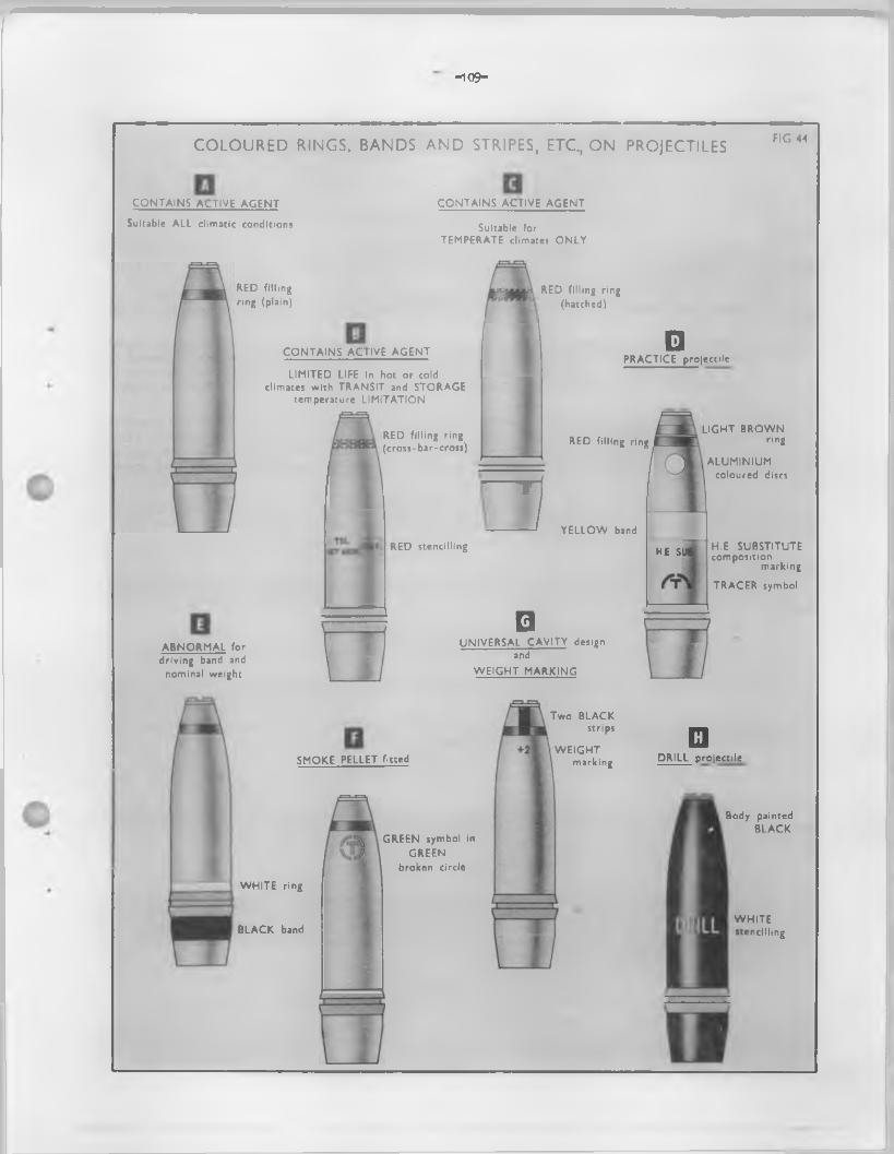
-109-
COLOURED RINGS, BANDS AND STRIPES, ETC., ON PROJECTILES FIG 44
CONTAINS ACTIVE AGENT
Suitable ALL climatic conditions
CONTAINS ACTIVE AGENT
Suitable forTEMPERATE climates ONLY
RED filling ring (plain)
ABNORMAL for driving band and
nominal weight
CONTAINS ACTIVE AGENT
LIMITED LIFE in hot or cold climates with TRANSIT and STORAGE
temperature LIMITATION
RED filling ring (cross-bar-cross)
RED stencilling
¥
RED filling ring (hatched)
□
□PRACTICE projectile
RED filling ring
YELLOW band
UNIVERSAL CAVITY design and
W EIGHT MARKING
H E. S
LIGHT BROWN ring
ALUMINIUM coloured discs
H.E SUBSTITUTEcomposition
marking
TRACER symbol
SMOKE PELLET fitted
WHITE ring
BLACK band
GREEN symbol in GREEN
broken circle
Two BLACKstrips
WEIGHTmarking
□DRILL projectile
Body painted BLACK
WHITEstencilling
—110—
375• Coloured stars - A star o f the appropriate colour (as applicable) denotes the presence o f a star f i l l i n g . Two stars o f the appropriate colour (as applicable) positioned one above the other denotes a change colour star un it, the colour o f the top star indicating the colour o f the star which appears f i r s t on e jection . A number in the same colour and positioned to the righ t and adjacent to the star denotes the number o f stars present. The le t t e r "M" or "MULTI" immediately below the star denotes the presence o f more than two star units when the exact number i s unimportant. The numeral or le t t e r (s ) (as applicable) are s ten cilled in not less than 1/2 inch bold type.
The le t t e r "S" in the same colour and positioned immediately below the star denotes a signal success.
The le t t e r "P" in the 3sme colour and positioned inmediately below the star denotes the star is suspended frcm a parachute. The mark o f the parachute (where applicable) is added a fte r the le t t e r e .g . "P6".
The le t te rs "S" and "P" (as applicable) are s ten c illed in not less than 1 inch bold type.The abbreviated code iden tify ing the particu lar s ta r composition i3 stencilled in black on the
body o f the sh e ll.NOTE:- An exception to the above occurs in the case o f shell which e jec t an illum inating or signal
(White) s ta r, where because the basic body colour o f the sh e ll i s white, the star symbol is stencilled in black. The le t t e r "P" followed by a code number indicating that the star is suspended from a parachute, w i l l i f applicable, be s ten cilled inmediately below the star.(P ig .47 ).
376. Shell with universal cavity - Land Service sh ell w ith an exploder cavity su itable fo r proximity (V .T .) fuzes are distinguished by two 1.1/2 inch v e r t ic a l black stripes diam etrically opposed, painted on the nose. They are painted over the rings (F ig.44G ). To avoid overpainting the r in g (s ) may be positioned approx. 1.1/2 inches below the l ip o f the sh ell so that the stripes terminate just above them.
377. H.E. shell su itable fo r fuzing without additional explodering - Certain Field. Branch A r t i l le r y shell f i l l e d H.E. with 2 inch fuze-hole, are issued with the top exploder in position . When such shell are issued plugged, the head o f the plug, i s painted lig h t b lue. (F ig . 45 ).
STEyiLLING (F igs .45 to 49)378. Calibre and mark o f ordnance - The ca lib re , id en tifica tion le t te r s and marie o f the ordnance is
s ten cilled above the type and mark o f the p ro je c t ile . The iden tify ing le tte rs approved are "H" fo r howitzer and "G" fo r gun e .g . : -
5.5 IN G 7.2 IN.H 3.7 G MK.6The mark o f the ordnance is emitted where the p ro je c t ile s are suitable fo r f ir in g in s ill marks
o f the same nature o f ordnance.In fu ture, when new equipments are introduced, the model number fo llow ed by the le t t e r A and a
seria l number w ill replace the "mark" previously used to id en tify the particu lar equipment i . e . , L2A1 •
379. Type and mark o f p ro je c t ile - The type and mark o f the p ro je c t ile is stencilled below the ca lib re , id en tifica tion and marie o f the ordnance, e . g . : -
HE MK.1 BE SMK MK.1AP MK.1 COL SMK BE MK.2
RED ( or colour as applicable)
In future, when new designs o f p ro je c t ile s are introduced, the model number followed by the le t t e r A and a s e r ia l number w i l l be stencilled a fte r the abbreviated le t te rs indicating the type o f the p ro je c t ile and w i l l replace the marie previously used to id en tify the design e . g . : -
SMK L2A1 CANSTR L6A1
For new designs o f rounds o f fixed Q.F. ammunition, the model number followed by the le t t e r A and a seria l number w i l l be emitted from the particu lars on the p ro je c t ile and w i l l be replaced by the part number allocated to the f i l l e d p ro je c t ile . In such instances the model number e .g . "L13A1" o f the complete assembled round w i l l be s ten c illed together with the type on the base o f the cartridge case or in such other position as may be approved e . g . : -
AP CANSTR HEL12A1 L9A1 L4A1
380. Type o f f i l l in g - The exact type o f f i l l i n g H.E., Smoke, e tc ., i s indicated by abbreviations or code le t te r s and numbers. A comprehensive l i s t o f codes fo r H.E. f i l l in g s is given in Appendix D while the l i s t o f codes o f smoke, illum inating, e tc . , corrpositions i s given in Table 2 Section 2 Part 1 o f the Joint Services Ammunition and Ammunition Package Markings Handbook.
_111_
Example 3: -A mixture is indicated by an oblique stroke e .g . , RDX/TNT 1 indicating a mixture o f
RDX and TNT o f certa in grades and in certa in proportions.A conposite f i l l i n g as opposed to a mixture i s indicated by a plus sign e .g . , 808 +
PEN 3.PA are the code le t te rs indicating a IN 443 smoke composition f i l l in g .
The abbreviations, code le t te rs and numbers are s ten cilled twice, diam etrically opposed, on p ro je c t ile s 6 inch ca libre and above, and once on others.
381. Method o f f i l l in g d e ta ils - P r io r to 1945 the design number o f the method o f f i l l in g was stencilled on the body o f the sh e ll. A fte r 1945 a method o f f i l l i n g code was adopted. Under this code the information and particulars o f the f i l l e r and date is s ten cilled in a single horizontal lin e around the ogive o f the p ro je c t ile . I t is ca lled the "one-line-code".
Example: - L10 CY 11/55 where: -
L i s fo r Land Service.10 i s the code number o f the method o f f i l l in g .CY is the f i l l in g contractor's in it ia ls or recognised marie.11/55 is the date o f f i l l i n g (month and year).
The code number o f the method o f f i l l in g i s governed by the d e ta ils o f the in it ia t in g system which in H.E. p ro je c t ile s , fo r exarrple, has the fo llow ing main variab les :-
S tee l or paper exploder containers.Depth o f cavity.Nature, number and size o f exploders or se r ia l number o f the tracer, etc.
On smoke p ro je c t ile s , the code number indicates deta ils o f the gunpowder burster and i t s f i l l in g , number and arrangement o f the smoke conposition containers.
The conplete code is kept by the Inspectorate o f Armaments. The main feature o f the method o f f i l l i n g design corresponding to the code markings w i l l be availab le to the Service in Regulations fo r the Army Ordnance Services, Volume 4.
NOTE: With the adoption o f the new "L" model numbering system fo r separate loading p ro je c t ilenomenclature, the " one-line-code" previously used to denote the type o f f i l l i n g w i l l be dispensed with, as particulars re la tin g to the nature and variations in the method o f f i l l in g w i l l be id en tified by the model number allocated to the store.With p ro je c t ile s which are components o f Q. P. fixed rounds, a f i l l e d part number w i l l replace the model number referred to above.
382. Weight markings - s ten c illin g o f (P ig . 44 ex.G ).Weight markings are applied in accordance with a "unit system" to Land Service separate loading,
sh e ll, except Q.P. 25 pr. sh e ll, star sh e ll, smoke sh e ll, chemical shell and fla re sh e ll, the units being based on the accuracy requirements o f each equipment.
The weight is the actual weight o f the f i l l e d sh e ll less the weight o f the plug but including the weight o f the standard fuze (and exploders) approved fo r use therewith. The fact that the shell may be issued plugged has no connection with the weight lim its s ten cilled on i t .
P ro je c t ile s within the normal dead weight lim its o f the range table standard are marked with an "0". Where the weight is not within these lim its , i . e . plus or minus, the shell is marked with a numeral, prefixed by a plus or minus sign (e .g . +1 or -1) to indicate, in terms o f units, the variation o f weight from the normal. The value o f the weight unit varies with the ca lib re , and may also vary according to the ro le o f the equipment (e .g . Coast A r t i l le r y weight units normally indicate fin er variations than those used in Field Army A r t i l le r y ) . Dead weight lim its are also fin e r fo r Coast A r t i l le r y p ro je c t ile s .
The value o f a unit in terms o f weight is given in the range table in which the correction columns are headed to indicate corrections corresponding to a variation o f one weight unit.
Flare shell, smoke sh e ll, chemical shell and star shell are not weight marked, the f ir s t because the weight is adjusted during manufacture, and the others because accurate b a ll is t ic s are not so inportant as fo r other types.
The reader should r e fe r to the appropriate range table fo r the value o f the weight unit in connection with any given shell.
383. Fuze deta ils - The marking "PZD IDT", followed by the lo t number, is stencilled on base fuzed shell.
When a p ro je c t ile which is issued, plugged, to the Service can be used with one type o f fuze only, the fo llow ing d e ta ils are stencilled on the body:- "USE No. ...................RJZE".
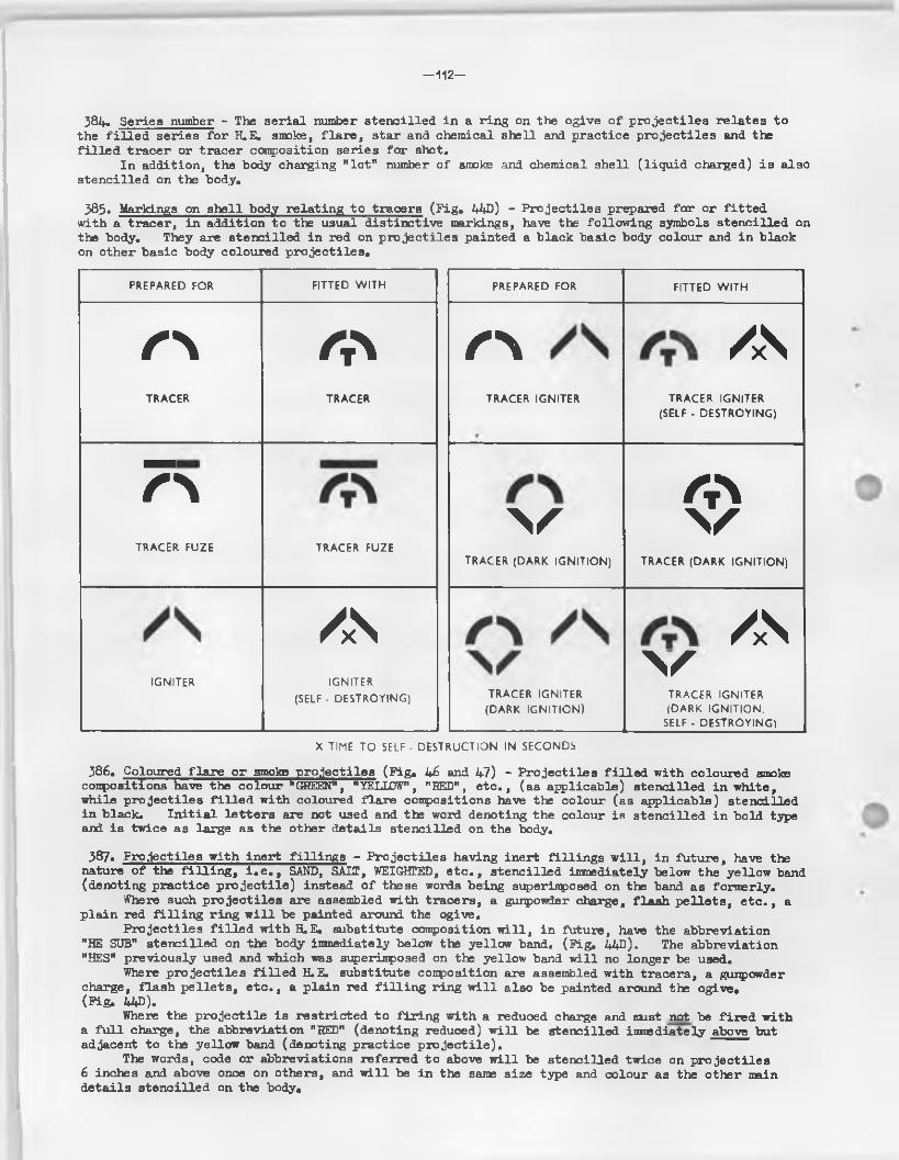
—112—
384. Series number - The se r ia l number sten cilled in a ring on the ogive o f p ro je c t ile s re la tes to the f i l l e d series fo r H.E. smoke, f la r e , star and chemical shell and practice p ro je c t ile s and the f i l l e d tracer or tracer composition series fo r shot.
In addition, the body charging " lo t " number o f smoke .and chemical shell ( l iq u id charged) is also s ten c illed on the body.
385. Markings on sh e ll body re la tin g to tracers (P ig* 44D) - P ro je c t ile s prepared fo r or f it te d with a tracer, in addition to the usual d is tin ctive markings, have the fo llow ing symbols s ten c illed on the body. They are s ten cilled in red on p ro je c t ile s painted a black basic body colour and in black on other basic body coloured p ro je c tile s .
PREPARED FOR FITTED WITH
/ ”\ /NTRACER IGNITER TRACER IGNITER
(SELF - DESTROYING)
\s <S>TRACER (DARK IGNITION) TRACER (DARK IGNITION)
V/S
TRACER IGNITER (DARK IGNITION)
TRACER IGNITER (DARK IGNITION.
SELF - DESTROYING)
PREPARED FOR FITTED WITH
r \ OTRACER TRACER
7\TRACER FUZE TRACER FUZE
/xSIGNITER IGNITER
(SELF - DESTROYING)
X TIME TO SELF - DESTRUCTION IN SECONDS
386. Coloured f la r e or smoke p ro je c t ile s (P ig , 46 and 47) - P ro je c t ile s f i l l e d with coloured smoke compositions have the colour "GREEN", "YELLOW", "REID", e tc . , (as applicable) s ten cilled in white, while p ro je c t ile s f i l l e d with coloured fla re compositions have the colour (as applicable) stencilled in black. In i t ia l le t te r s are not used and the word denoting the colour is s ten c illed in bold type and is twice as large as the other deta ils stencilled on the body.
387. P ro je c t ile s w ith in ert f i l l in g s - P ro je c t ile s having inert f i l l in g s w i l l , in fu ture, have tte nature o f the f i l l i n g , i . e . , SAND, SALT, WEIGHTED, e t c . , stencilled immediately below the yellow band (denoting practice p ro je c t ile ) instead o f these words being superimposed on the band as formerly.
Where such p ro je c t ile s are assembled with tracers, a gunpowder charge, f lash p e lle ts , e t c . , a p la in red f i l l i n g r in g w i l l be painted around the ogive.
P ro je c t ile s f i l l e d w ith H.E. substitute composition w i l l , in future, have the abbreviation "HE SUB" stencilled on the body immediately below the yellow band. (P ig , 44D). The abbreviation "HES" previously used and which was superimposed on the yellow band w i l l no longer be used.
Where p ro je c t ile s f i l l e d H.E. substitute composition are assembled with tracers, a gunpowder charge, flash p e lle ts , e tc . , a p la in red f i l l i n g rin g w i l l also be painted around t te ogive,(P ig . 44D).
Where the p ro je c t ile is res tr ic ted to f ir in g w ith a reduced charge and must not be f ir e d with a fu l l charge, the abbreviation "RED" (denoting reduced) w i l l be stencilled imnsdiately above but adjacent to the yellow band (denoting practice p ro je c t ile ).
The words, code or abbreviations referred to above w i l l be stencilled twice on p ro je c t ile s 6 inches and above once on others, and w i l l be in the same s ize type and colour as the other main d e ta ils s ten cilled on the body.

- 113 -
TYPICAL IDENTIFICATION MARKINGS FOR H.E. FILLED SHELL f ig .45
KEY TOBASIC BODY PAINTING C O D E L.7
to M of F Design D2 (L) 554/GF/229
WITH UNIVERSAL CAVITY
Bod/ painted BUFF
MARKINGS ON REVERSE SIDE
KEY TO STENCILLED MARKINGS
25 PR G ... Calibre and Identification Letter of Ordnance
HE MK I ......Type and Mark of Projectile
RDX/TNT.I. Nature of Filling code abbreviation
(123).............. Filled Series Lot Number
L7 CY 3/57.One line code for Method of Filling
CODE L.7to M of F Design DD (L) 18851
CODE L.6to M of F Design DD (L) I8I7I
MARKINGS ON REVERSE SIDE
KEY TO STENCILLED MARKINGS
25 PR G ......... Calibre and IdentificationLetter of Ordnance
HE MK I .......... .Type and Mark of Projectile
A M ?^ NT'3 ) - " N*ture of Filling code > abbreviation
^ \ *^°}...One line code for Method 16 CY 1/51 J of Filling
(456) (78^).........Filled Series Lot Number
MARKINGS ON REVERSE SIDE
Painted GREEN. Indicates w Smoke Pellet fitted
X- X“X” Indicates limited life Inhot or cold climates
BLACKstencilling
BLUE plug
Two BLACK stripes
-nU-
TYPICAL IDENTIFICATION MARKINGS FOR SMOKE SHELLFIG .46
KEY T O BASIC BO D Y PA IN TIN G FOR A LL SM OKE SHELL
/ \
BLA CKstencilling
SCR EEN IN G SMOKE
C O D E L 33 to M of F Design D2 (L) 1528/GF 135
SMK BE
KEY T O S T E N C ILLED M ARKINGS
25 PR G Calibre and Identification Letterof Ordnance
^MK Type and Mark of Projectile
L33 CY 3/55 One line code for Method of Filling
GE Code denoting Main Filling compositionof Smoke containers
^23^) .......Filled Series Lot Number
25 PR G ........ Calibre and identification Letterof Ordnance
COL SMK BEyjype ancj Mar|( 0f Projectile MK I J
RED Colour of smoke produced(or GREEN,BLUE orYELLOW)
L33/4 CY 5/55 One line code for Method of Filling
PN 443 Code denoting Main Filling compositionof Smoke containers
(456) Filled Series Lot Number
ScreeningSmoke
W H IT Estencilling
ColouredSmoke
MARKINGS ON REVERSE SIDE
C O LO U R E D SMOKE
C O D E L 33/4to M of F Design
D2 (L) 1528/GF 135
BLA CKstencilling
MARKINGS ON REVERSE SIDE
-115-
TYPICAL IDENTIFICATION MARKINGS FOR FLARE SHELL AND STAR SHELLFIG .47
KEY T O BASIC BO D Y P A IN T IN G FOR A LL FLARE A N D STAR SHELL
FLARE
C O D E L 45/3 to M of F Design D2 (L)449/GF, ,93
RED filling ring
Body paintedW H ITE
NOTE Driving band for STAR Shell is in lower position
BLA CKstencilling
MARKINGS ON REVERSE SIDE
KEY T O STE N C ILLED M ARKIN GS
25 PR G — Calibre and Identification Letter ofOrdnance
- V k Y E ) ^ P * an< Projectile
RED (or GREENor YEU QW) Colour of flare produced
145 3 CY 4 56 One line code for Method of Filling
TB Code denoting main filling of___ Flare Container
. (123) •••• Filled Series Lot Number
25 PR G • Calibre and Identification Letter ofOrdnance
"^MK ^ Type anti ^ arl< Pr° j ecti'e
£ .............Indicates STAR filling
P...............Indicates fitted with Parachute
135 CY 5, 55 •• One line code for Method of Filling
GA ••••....... Code denoting main filling of.— ^ Star Case
(456)....'.. .Filled Series Lot Number
STAR (ILLU M IN A TIN G OR W H IT E SIG N A L)
C O D E L 35 to M of F Design DD(L) 17894
> Flare Shell
BLA CKstencilling
Star Shell
V
-1 16-
TYPICAL IDENTIFICATION MARKINGS FOR INCENDIARY SHELL FIG.48
KEY T O BASIC B O D Y P A IN T IN G FOR A LL IN C E N D IA R Y SHELL
S/L BE IN C E N D IA R Y
C O D E L 33 9 to M of F Design D D (L) I ! !82
REDfilling ring
Body painted RED O X ID E
BLA CKstencilling
MARKINGS ON REVERSE SIDE
KEY T O STE N CILLED M ARKIN GS
25 PR G .......... Calibre and Identification Letter of Ordnance
.NCDY| BEj, j y pe ancj Mark of Projectile
.............. Filled Series Lot Number
L33/9 CY 1/55.One line code for Method of Filling ................. Code denoting Main Filling
of Incendiary Containers
TYPICAL IDENTIFICATION MARKINGS FOR A.P. (ARMOUR PIERCING) SHOT FIG.49(w i t h t r a c e r )
KEY T O BASIC BO D Y P A IN TIN G
REDfilling ring
Body painted BLA CK
REDstencilling
C O D E L 32 to M of F Design D 2(L) 1451 GF 122
MARKINGS ON REVERSE SIDE
KEY T O STEN CILLED M ARKINGS
25 PR G ......Calibre and Identification Letter of Ordnance
AP MK 8....... Type and Mark of Projectile
/^ T 'N ............ Denotes Tracer filling
^ 2 ^ ............ Filled Series Lot Number
L32 CY 3 55 .One line code for Method of Filling _______
—117—
388. P ro jec tiles - d r i l lD r i l l p ro je c t ile s painted black have the word DRILL prominently stencilled in white, in two
places on p ro je c t ile s 6 inch ca lib re and above, and once on others (F ig . 44 ex.H).
MORTAR BOMBS3&9» S tencillin g , rings, symbols, e tc .
With the exception o f mortar bombs f i l l e d H.E., which are s ten c illed in white le tte r in g , a l l natures o f bombs are id en tified by the same colour o f s ten c illin g , rings and symbols as a.^proved fo r p ro je c t ile s . These particulars are applied in re la t iv e ly the same sequence but owing to the d ifference in shape, the actual position on the body may vaxy s lig h t ly .
FUZES390. Fuze body
S ta m p in g s:-
Number and mark o f fuze.Contractor's in it ia ls or recognized trade mark.Year o f manufacture.Series lo t number.F il l in g contractor's in i t ia ls or recognized trade mark.Date o f f i l l i n g (month and y e a r )•F ille d lo t number.
Painting - Basic colours are not used on body or cover fo r id en tifica tion except in the case o f certa in marks o f No.162 fuzes approved fo r use in M.L. 4.2 inch mortar bombs which are distinguished by the whole o f the outside o f the safety cap being coloured blue, with the fuze nomenclature on top o f the cap f i l l e d in red. In addition, the w alls o f the brass cover are painted blue.
NOTE: The red f i l l in g ring, as found fo r example on f i l l e d p ro je c t ile s , is not used on fuzes.
391 • Fuze coversS ta m p in g s:-
Number and mark o f fuze cover.Manufacturer's in i t ia ls or recognized trade mark.Number and marie o f fuze.F il l in g contractor's in i t ia ls or recognized trade mark.Date o f f i l l i n g (month and yea r).F illed lo t number o f fuze.
392. TracersStam pings: -
Number and mark o f tracer.Contractor's in it ia ls or recognized trade mark.Year o f manufacture.Series lo t number.F il l in g contractor's in i t ia ls or recognized trade mark.Date o f f i l l i n g (month and yea r).F il le d lo t number.
-1 1 8 -
Chapter 12
Identification Colours and Markingso
Section 4. Packages
ImportantI t should be noted that the mrMnjLS-de^ortbed following paragraphs, vary in certain
instances considerably from past practice and naturally packages o f past and current issue w i l l , at times, ex ist together with d ifferent markings placed In d ifferen t positions.
METB3D OF COLOUR IDENTUTCATION AND MARKINGS (P ig s . 50 to 5k)393* Packages w i l l normally be identified by one o r more o f the follow ing:-
Basic colour.Stencilling.Stamping, embossing and branding.Labels.Metal tags.
394* Basic body colours - Packages, with the exception o f those described in para. 397 below, are painted a distinctive colour as shown:-
395* Outer packages - Wooden and ungalvanised steel outer packages are painted a basic colour o f service brown except those containing chemical anrounition which are painted ligh t grey.
396. Inner oontainers - Removable inner containers (including tinplate cylinders and boxes) are normally painted service brown o r blaok, except those containing detonators which are painted red and those containing chemical stores which are painted ligh t grey.
Tinned-plate lin ings (not removable). These may be painted o r varnished blaok for protection purposes. The colour has no significance.
397. Exceptions - Packages and oontainers made from the following materials w i l l not normally be painted, they may, however, can y such special identification as necessary.
Cellulose containers (except when used as an outer package)Galvanised steel packagesPackages made o f : -
lig h t a lloy* Resin-bonded plywood
Fibre glass
398. Coloured bands on packages - Coloured bands have no Inter-Service significance and are reserved fo r special purposes and fo r international use as necessary.
399. Stencilling - Stencilling on packages, containers, e to ., i s intended to provide the user and the s to reholder with a l l the necessary information to read ily identify the contents, their f i l l in g and their Government explosive c lassification group, etc. These consist o f : -
(a ) Quantity and descriptive nomenclature - The quantity and approved abbreviated nomenclature and mark o f contents.In the case o f B.L. and Q.F. separate loading cartridges the nominal charge weight w i l l be shown i f this i s included in the approved nomenclature.
(b ) Components - Detailed information regarding components o f the store.
(o ) Government explosive c lassification group - This w i l l normally be applied by stencilling or by a stamp.
(d ) Operational markings — In the Lend Service, additional deta ils known as "operationalmarkings" are used. These consist o f bold ly stencilled abbreviations which enable the
_1 1 9 _
user in an operational area to id en tify quickly the store he requires. Operational abbreviations, are not used an packages containing practice, d r i l l , chinny, instructional, blank or proof stores.
A l i s t o f approved operational abbreviations i s given in para. U2J+.
400. Special de ta ils or symbols - Particulars o f these are given in para. 403.
401. Colour o f s ten c illin g - The fo llow ing colours are normally used fo r s ten c illin g on packages: -
Quantity ) Nomenclature and ) component d e ta ils )
Golden yellow.(On unpainted packages black may be used i f th is affords greater v is ib i l i t y ) .
Government explosive) White on a dark basic coloured background and signal red on a lig h tc la ss ifica tion group) basic coloured background.
Safety distance category. White Operational markings."S .A .S ."
R estrictive sentences and Signal red. temperature lim itations.
402. Position - The position o f s ten c illin g on p>ackages depends on various factors such as :-
Operational and user requirements. Method o f stowage or stacking.Design o f package. Particulars o f contents, etc.
To avoid s ten c illin g and/or symbols being removed or defaced in handling, stacking or stowage, these particulars should where possib le, be positioned in recessed panels, or in recesses between raised panels or flu tin g o f s tee l packages and cylinders and between battens o f wooden packages.
The fo llow ing particulars are normally s ten c illed as shown:-
Outer packages On l id or top
Government explosive group c la ss ifica tion symbol or label.Safely distance category.Operational abbreviation.*'S.A.S.M (when applicable).
On side or front
Quantity o f items packed.Approved abbreviated descriptive nomenclature and mark o f complete store.Quantity o f inner packages, and "type ( where applicable).Lot or batch number i f ammunition is batched.Type, s ize and lo t number o f propellant ( i f aramn. is not batched).Nature o f f i l l i n g o f sh e ll, bombs, e tc ., (as applicab le).Method o f f i l l i n g code (Land Service, Q.P. separate loading sh ell on iy ) .P il le d series number o f p ro je c t ile (Land Service on packages containing plugged or
fuzed separate loading p ro je c t ile s ).Assemblers or f i l l e r s recognized mark or in it ia ls .Date o f assembly or f i l l i n g (month and year).Propellant id en tifica tion code.Approved abbreviated descriptive nomenclature, mark, lo t number, in it ia ls o f f i l l e r
and year o f f i l l i n g o f component stares, e .g . ,
FZ 117-15 = 123-CY-56H? 9-3 = 123-CY-56 (on packages containing Q.P. separate cartridges)
The follov/ing w i l l also be s ten c illed when applicable: -
Tracer symbol ) a3 marked on p ro je c t ileSmoke box or p e lle t symbol )
”DEC" denoting special decoppering rounds."H.V." indicating High ve lo c ity charges or rounds.
-120-
LATEST APPROVED IDENTIFICATION MARKINGS FOR STEEL BOX hg.50 FOR SEPARATE LOADING SHELL
T Y P IC A L FO R 25 PR PROJECTILES
Box painted B R O W N
W H IT E stencilling
Y E L L O W stencilling
Y E L L O W stencilling
K EY T O S T E N C IL L E D M ARKIN GS
O N LID
25 PR HE FZD i 17 ...Approved Operational Abbreviation...............................Government Explosive Classification label
(with Group Number as applicable)X .................... ..............Safety Distance category
O N FR O N T SIDE
2 .......................................Quantity of items packedSHELL 25 PR HE MK i...Abbreviated Nomenclature and Mark of
complete storeU - ( w h e n a p p l ic a b le ) ......Denotes shell filled to "Universal Cavity" design,R D X/TN T........................ Nature of Filling of ShellL7-GD-4-56....... ............ One line Code-Method of Filling of Projectile123.....................................Filled Series Lot number of Shell
The above markings are applicable to boxes for H E. shell. Boxes for Screening Smoke, Coloured Smoke, Flare. Incendiary. Star, and Chemical shell are similarly marked, but with the following differences
O N R.H. EN D
123 .... .Filled Series Lot number of ShellG D ..........Recognized Mark (or initials) of Filler4-56........ Date of Filling (month and year)1 1 2 .. . ..... Package serial number69 IB ..... Weight of complete package
FZ 117-15. Designation and Mark231............. Lot NumberC Y -5 5........ Recognized Mark (or initials) of
Filler and Year of
of Main ‘ Component
Screening Smoke Coloured Smoke Flare Incendiary Star ChemicalColour of box Brown Brown Brown Brown Brown Grey
Approved Operational Abbreviation
25PR BE SMK FZD * or 25PR BE SMK PLGD
25PR SMK RED?1 FZD * or 25PR SMK RED PLGD
25PR FLAR GREEN/ FZD * or 25PR FLAR GREEN PLGD
25PR INCDY FZD * or 25PR INCDY PLGD
25PR STAR FZD * or 25PR STAR PLGD
25PR CHEM Y4
Gov't Explosive Classification Group II II 6 II 6 13
Safety Distance Category X X X Y X None
Abbrev. Nomenclature and Mark
SHELL 25PR SMOKE BE MK0
SHELL 25PR COL SMOKE BE
RED/MK0
SHELL 25PR COL FLARE BE
GREENfM K/
SHELL 25PR INCDY M K/
SHELL 25PR STAR MK/
SHELL 25PR CHEMICAL MK/
# No. of Fuze (as applicable)
t Colour produced (as applicable)
0 Mark of Shell (as applicable)
Other markings, such as One Line Code for Method of Filling. Number and Mark of Fuze. Weight of Package, etc, vary according to the differences in contents.Markings for Nature of Filling are a requirement for H.E. shell boxes only.
— 1 2 1 —
On righ t hand end
Package se r ia l number Batch numberGross weight ( lb . ) or
Lot number and in it ia ls o f f i l l e r and date o f f i l l in g (month and yea r).
The f i l l e d lo t number, in i t ia ls or recognized monogram o f f i l l e r and date o f f i l l in g (month and year) are s ten c illed on package containing separate loading sh e ll, fuzes, primers, pyrotechnics, rocket motors, e tc .The batch number, in i t ia ls or recognized monogram o f the assembly factory and year o f assembly are stencilled on packages containing assembled Q.F. fixed cartridges, mortar bombs, assembled rockets e tc .
Inner containers
When ammunition or components are packed in closed inner containers which can be removed from the outer package, each inner container is s ten cilled with the fo llow ing particu lars:-
"EXPLOSIVE", when the stores or components packed f a l l w ith in one o f the Government explosive c la ss ifica tion groups. This s ten c illin g w i l l be in red, except fo r cylinders containing detonators when i t w il l be in black. The word "EXPLOSIVE" is not applied on inner containers holding safety cartridges, primers fo r Q.P. cartridges, tubes or containers o f a small s ize containing sim ilar stores.
Quantity, nomenclature and marie o f items packed, together with batch; lo t or se ria l number, in it ia ls or monogram o f f i l l e r , date o f f i l l i n g (month and y ea r ). This s ten c illin g w i l l be in the colour and s ize o f type best suited to the particu lar container.
In the case o f tinplate containers, t in printing or transfers may be used in l ie u o f stencillingo
403 • Additional s ten c illin g - The following particu lars w i l l also be sten cilled on outer packages in an approved position when required:-
(a ) R estr ic tive sentences - in signal red
(b ) Climatic and fir in g temperatures and res tr ic ted service l i f e lim itations
The under-mentioned particu lars, when applicable, are s ten c illed in signal red in bold le tte r in g on the l id or top and on the l e f t hand side or end o f rectangular packages and along the side o f metal cy lind rica l packages
Climatic and temperature lim itations
Outer and inner packages containing ammunition res tricted to transit, issue and storage to certain clim atic and tenperature conditions are marked as fo llow s :-
LIM . . . indicated lim ited l i f e in hot (o r co ld ) climates. I t is cautionary warning denoting the contents should be frequently inspected arri/or tested to confirm th e ir continued serv iceab ility .
TEMP... indicating tran s it, issue and storage lim ited to temperate climates only.
In special instances, where the store is res tr ic ted in transit and storage to below or above a specified defined temperature, the c r it ic a l temperature figures enclosed in a rectangle preceded by the le tte rs TSL (denoting transit and storage temperature lim ita tion ) and the words "HOT ABOVE" or "NOT BELOW" (as applicable) replace the abbreviation "LIM" or "TEMP"• e .g .
TSL NOT ABOVE 1120F | (actual temperature figure as applicable)
or
TSL NOT BELOW |-25Fl ( " )
Where applicable the above-mentioned indications may be amalgamated, underneath one another, in which case the words "NOT ABOVE" or "NOT BELOW"
eith er follow ing or w i l l be omitted.
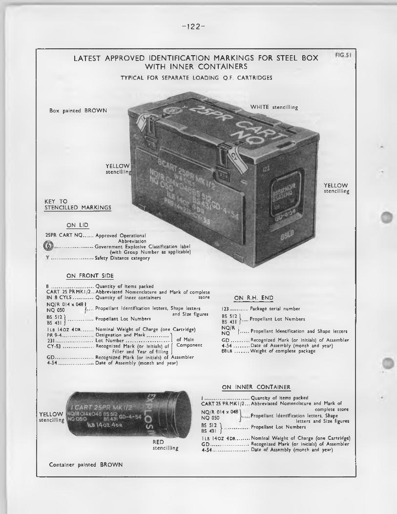
- 1 2 2 -
LATEST APPROVED IDENTIFICATION MARKINGS FOR STEEL BOXW ITH INNER CONTAINERS
T Y P IC A L FOR SEPARATE L O A D IN G Q .F. C A R T R ID G E S
Y E L L O Wstencillin
K EY T OS T E N C IL L E D M ARKIN GS
W H IT E stencilling
O N LID
25PR CART NQ. Approved Operational Abbreviation
Government Explosive Classification label (with Group Number as applicable)
Safety Distance category
Box painted B R O W N
Y E L L O Wstencilling
O N F R O N T SIDE
8 ................................Quantity of items packedCART 25 PRM K1/2 ..Abbreviated Nomenclature and Mark of completeIN 8 C Y L S ............... Quantity of inner containers storeNQ/R 014 x 0481 ,NQ 050 r.... Propellant Identification letters, Shape lettersnc e n l and Size figures“ ->IZ l ................... Propellant Lot NumbersBS 431 JI LB I40Z 4DR......... Nominal Weight of Charge (one Cartridge)PR 9-4....................... Designation and Mark................ )231............................ Lot Number..................................I of MainCY-53 ....................... Recognized Mark (or initials) of [ Component
Filler and Year of filling JG D ............................. Recognized Mark (or initials) of Assembler4-54.........................j. Date of Assembly (month and year)
O N R.H. EN D
123.... BS 512 BS 431 NQ/R NQ G D .. . 4 -54 .. 88 LB ..
...... Package serial number
j.... Propellant Lot Numbers
[■...... Propellant Identification and Shape letters
....... Recognized Mark (or initials) of Assembler........ Date of Assembly (month and year)....... Weight of complete package
Y E L L O Wstencilling
REDstencilling
O N IN N ER C O N T A IN E R
I ..................................Quantity of items packedCART25 PRMKI/2...Abbreviated Nomenclature and Mark of
NQ/R 014x048 NQ 050
complete storePropellant Identification letters, Shape
letters and Size figuresBS SI2 \ ...................Propellant Lot NumbersBS 431 ] ^
I LB I40Z 4DR......... Nominal Weight of Charge (one Cartridge)G D ............................. Recognized Mark (or initials) of Assembler4-54........................... Date of Assembly (month and year)
Container painted B R O W N
-1 2 3 -
F iring temperature lim itationsWhere shown on the ammunition store, the f ir in g temperature lim ita tion figures in a
c irc le is reproduced on the outer package, e . g . ,
Date o f expiry o f or res tr ic ted Service l i f eWhere shown on the ammunition 3tore, the res tricted Service l i f e or date o f expiry o f
Service l i f e , is reproduced in red s ten c illin g on the outer package, e .g . ,
S.L. (denoting Service l i f e ) followed hy the date (month and year) i . e . "SL 8/56".
i+Dif. Unsuitable fo r a ir dropping - Packages containing ammunition or explosives which are unsuitable fo r a ir dropping are marked with a red equ ila tera l tr ia n g le , the base o f which should be 1.1/2 inches approx. This symbol is s ten cilled on the l id or top and on one end o f the package.
405* Safety distance category - This i s stencilled in white in not less than 1/2 inch type above the Government explosive c la ss ifica tion group-symbol.
The Safety distance category comprises a one or two le t t e r code, and w i l l be found in column 9 o f the table in the "Comprehensive C lassified L is t o f Government Explosives".
436. Special ammunition stowage in fre igh t ships - Packages containing explosives in th is category which comprises a l l group 12 (phosphide o r white phosphorus charged ammunition) a l l group 13 (chemical ammunition) and ammunition in group 11 charged EM or CSAM, are scheduled fo r special conditions o f stowage in fre igh t ships. Such packages have the sea transport code abbreviation "SAS" stencilled on in not less than 1/2 inch type in the sane colour as and just below the Explosive group c la ss ifica tion symbol,, F u ll d e ta ils o f the code le t t e r used are given in column 7 (opposite the generic transport designation o f the store concerned) in the table in the "Conprehensive C lassified la s t o f Government Explosives".
NOTE: The le t te rs "D" and "E? which appear with the code "SAS" in the Conprehensive C lassifiedL ist are not stencilled on packages.
407* Dangerous and inflammable goods - A l l outer packages containing ammunition which, because o f the nature o f i t s f i l l i n g or charging, are not c la ss ified fo r storage and transport in an explosive group, but are c la ss ified by the M inistry o f Transport or B ritish Railways as "dangerous goods", are stencilled to indicate the follow ing particu lars:-
Nature o f contents (e . g . , titanium tetrach loride, bromine).Type o f danger (e . g . , corrosive, poisonous or inflammable)0Flash point c la ss ifica tion o f the inflanmable goods within the fo llow ing recognised groups: -
Those with a fla sh point below 73°F« and which are not soluble in water w i l l be s ten c illed :-
"HIGHLY INFIAMMABIE F.P. BELOW 73°F."
Those with a fla sh point below 73°F. and which are soluble in water w i l l be s ten c illed :-
"INFLAMMABLE F.P. BELOW 73°F."
Those with a flash point between 73°F» and 150°F. w i l l be s ten c illed :-
"INFLAMMABIE F.P. BETWEEN 73°S/150°F."
408. Shell - universal cavity - A "U" on the package indicates that i t contains sh e ll with "universal cavity" i . e . , a cavity suitable fo r both normal and V.T. fuzes.
409. NATO symbol o f interchangeability - A symbol, representing a four leaved clover, is used to guarantee, fo r the benefit o f NATO Armed Forces, that certain ammunition is operationally interchangeable.
This symbol when sten cilled on outer packages in p lies that the contents have been established as conforming as regards conposition, make and se rv iceab ility to a model approved under the provisions la id down in a NATO standardization agreement, brought up-to-date as necessary. The stores w i l l therefore be operationally interchangeable with ammunition o f the same designation, type and ca lib re , which bears the same symbol, in a l l equipment fo r which such ammunition is normally used.
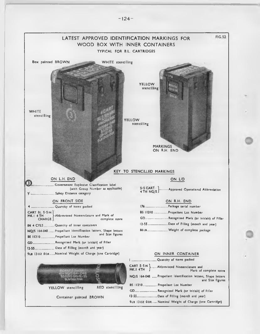
- 124-
LATEST APPROVED IDENTIFICATION MARKINGS FOR W OOD BOX WITH INNER CONTAINERS
T Y P IC A L FOR B.L. C A R T R ID G E S
Y E L L O Wstencilling
O N R.H. E N D
Box painted B R O W N W H IT E stencilling
W H IT E • stencilling
Y E L L O Wstencilling
T O S T E N C IL L E D M A R K IN G S
O N LID
4TH *N JQ /s}.........Approved Operational Abbreviation
KEY
O N L .H . E N D
Government Explosive Classification label(with Group Number as applicable)
Safety Distance category
O N F R O N T SIDE
4 .................CART BL 5-5 IN MK.I 4 TH
CHARGE
IN 4 CY LS.........
NQ/S 164-048...
BS 1 1210............
G D .....................
12-55...................
Quantity of items packed
Abbreviated Nomenclature and Mark ofcomplete store
Quantity of inner containers
Propellant Identification letters, Shape letters_ „ . and Size figuresPropellant Lot Number
Recognized Mark (or initials) of Filler
Date of Filling (month and year)
O N R.H . E N D
176..........................Package serial number
BS 1 1210 ................ Propellant Lot Number
G D ..........................Recognized Mark (or initials) of Filler
12-55.......................Date of Filling (month and year)
8 6LB....................... Weight of complete package
9LB I30Z ODR ....Nominal Weight of Charge (one Cartridge) O N IN N ER C O N T A IN E R
Y E L L O W stencilling RED stencilling
Container painted B R O W N
I ................ .CART 5-5IN \ MK.I 4TH /
Quantity of items packed
Abbreviated Nomenclature andMark of complete store
NQ/S 164-048 ....Propellant Identification letters, Shape lettersand Size figures
BS 1 1210................ Propellant Lot Number
G D ......................... Recognized Mark (or initials) of Filler
12-55....................... Date of Filling (month and year)
9LB I30 Z ODR.... Nominal Weight of Charge (one Cartridge)
-1 2 5 -
PositionI t i s s ten c illed in a prominent position on the face (s ) o f the package on which d e ta ils o f
the contents appear.
Dimensions and colourThe dimensions o f the symbol i s not to be less than the height o f the largest printed
character used fo r the normal id en tifica tion markings ( type and/or c a lib re ), nor is i t to be larger than twice th is height.
The colour o f the symbol w i l l be the same as that o f the other main id en tifica tion deta ils s ten cilled on the same face.
Cancellation o f symbolWhen selecting the position and method o f applying the symbol, consideration is given to
the possible necessity o f removing or ob lite ra tin g i t , should the contents cease to f u l f i l , at any time, the conditions implied by the presence o f the symbol.
410. U.S./U.K. symbol denoting standardization design - A symbol (kJ i s stencilled on packages containing ammunition which is manufactured to a standardized design approved fo r weapons which are equipment o f both the U.S. and U.K. Armed Forces.
PositionI t is stencilled in a prominent position on the fa ce (s ) o f the package on which the main
deta ils o f the contents appear.
Dimensions and colourThe dimensions o f the symbol i s not to be less than the height o f the la rgest printed
character used fo r the normal id en tifica tion markings (type and/or ca lib re ), nor i s i t to be larger than twice th is height.
The colour o f the symbol w i l l be the same as that o f the other main id en tifica tion d e ta ils s ten c illed on the same face.
411. Part packages - When packages do not contain the fu l l approved complement o f stores, the word FRACTION (o r FRAC)is s ten c illed in bold type in red on the l id or top and on one side.
The "quantity o f items packed" where sten cilled on the package is amended to agree.
412. For individual Services - Additional s ten c illin g usually o f a self-explanatory nature is sometimes applied by individual Services fo r a particu lar purpose. For example, packages o f stores bearing symbol may be expected to carry more or d iffe ren t d e ta il and markings than th e ir purely B ritish Service counterparts, to meet the U.S. user requirements in addition to B ritish requirements.
413* Stamping, embossing and branding - Empty packages have the fo llow ing particulars stan^d, embossed or branded by the maker:-
Box le t t e r , number and mark.Recognized in it ia ls o r monogram o f manufacturer.Year o f manufacture.
On metal packages th is information is embossed, on wooden packages i t is stamped or branded. Cellu losic containers cannot be embossed, stamped or branded; i t is therefore usual to sten c il the particulars o f the empty package, or to stamp or emboss the metal ends.
414. Government explosive c la ss ifica tion group label - Packages containing stores c la ss ified fo r storage and transport in an explosive group may be labe lled , instead o f the symbol being sten cilled on, with a group label canying a group number which denotes the conditions under which the package is to be transported and stored (see Comprehensive C lassified L is t o f Government Explosives),
The Government explosive group label used in each Service is as as follows
Naval Service
Land Service
A ir Service
- Red on white background, with "N" to indicate Naval Service.
- Red on white background, with "W V D" to indicate Land Service.
- Red on white background, with "RAF" to indicate A ir Service.
Ministry o f Supply - Red on white background, with "MDS" to indicate M inistry o f Supply,
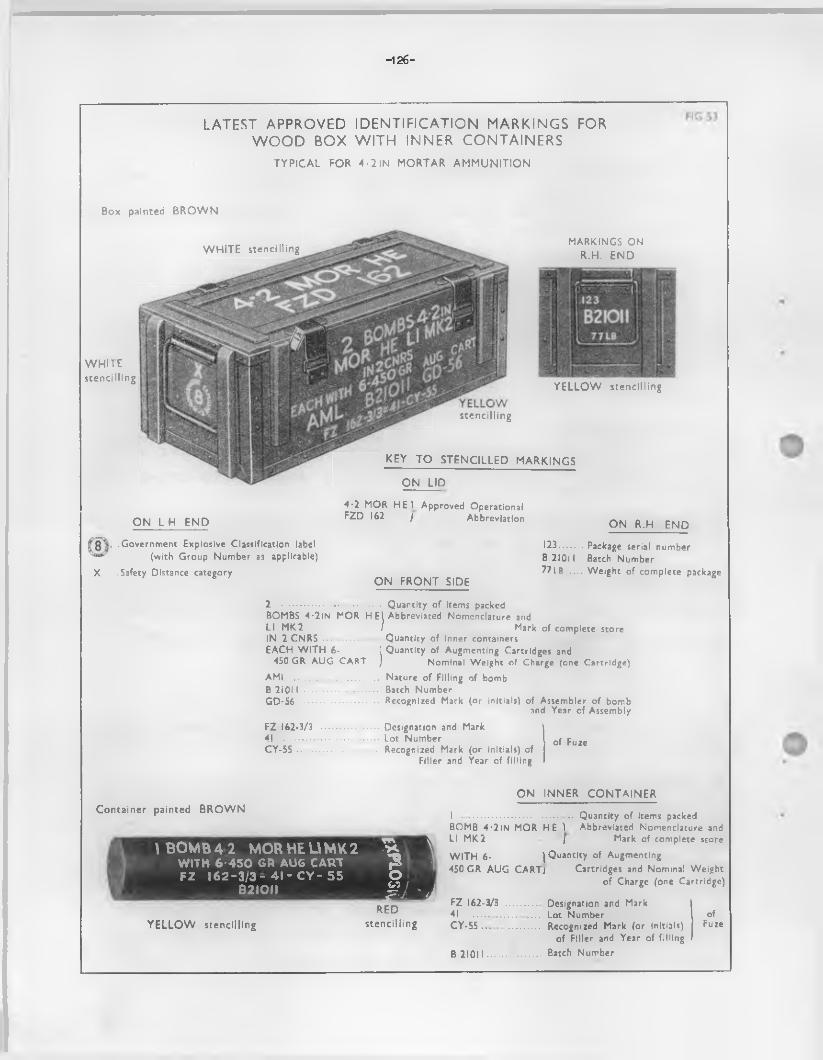
-126-
LATEST APPROVED IDENTIFICATION MARKINGS FOR W OOD BOX WITH INNER CONTAINERS
T Y P IC A L FOR 4 - 2 IN M ORTAR A M M U N ITIO N
Box painted B R O W N
W H IT E stencilling
W H IT Estencilling
K EY T O S TE N C IL LE D
O N LID
stencilling
MARKINGS ONR.H. EN D
Y E L L O W stencilling
M ARKIN GS
O N L H EN D4-2 MOR H E 1 Approved Operational FZD 162 ) Abbreviation
O N R.H. EN D
..Government Explosive Classification label (with Group Number as applicable)
X .Safety Distance categoryO N F R O N T SIDE
123.........Package serial numberB 21011 Batch Number77IB ...... Weight of complete package
2 ..................................... Quantity of items packedBOMBS 4-2lN MOR H E’( Abbreviated Nomenclature andLI MK2 / Mark of complete storeIN 2 CNRS ..................... Quantity of inner containersEACH W ITH 6 - 1 Quantity of Augmenting Cartridges and
450 GR AUG CART ) Nominal Weight of Charge (one Cartridge)AML ................................ Nature of Filling of bombB 2iO II ........................... Batch NumberGD-S6 ............................ Recognized Mark (or initials) of Assembler of bomb
and Year of AssemblyFZ 162-3/3 ..................... Designation and Mark41 .................................... Lot Number of FuzeC Y -5 5 .............................. Recognized Mark (or initials) of
Filler and Year of filling
Container painted B R O W N
\ BOMB 4 2 MORHEUMK2WITH 6 '4 5 0 GR AUG CARTFZ 1 6 2 - 3 / 3 - 4 1 -C Y - 55
B2 IO II
1 1
I l a
YELLOW stencillingRED
stencilling
O N IN N ER C O N T A IN E R
I .............................. ........... Quantity of items packedBOMB 4 -2 IN MOR HE 1 Abbreviated Nomenclature and LI MK2 ] Mark of complete storeW ITH 6- (Quantity of Augmenting450 GR AUG CARTi Cartridges and Nominal Weight
of Charge (one Cartridge)
FZ 162-3/3 ............. Designation and Mark41 ......................... Lot Number ofC Y -5 5 ....... ............ Recognized Mark (or initials) Fuze
of Filler and Year of filling B 21011 .................... Batch Number
-1 2 7 -
I t w i ll normally be applied once on the l id or top o f the outer package, adjacent to , but clear o f the operational abbreviation ( i f applied).
415» Dangerous goods labels - Special labels are required to be a ffix ed to outer packages containing ammunition c la ss ified as "dangerous goods" in the "corrosive" or "poisonous" classes. The labels o fspecified dimensions and colours as shown, are each marked near the top with one o f the " t r a f f icle t te rs " "A, B, C" e tc . These le t te r s , as applicable, are shown against the "corrosive" and "poisonous" items in the "dangerous goods" lis te d by B ritish Railways to indicate the labels whichmust be used. Packages which have contained dangerous goods in the "A" or "C" classes must also bearthe "A" or "C" labels when being returned as eupties.
416. Packers label - On every occasion o f closing or reclosing any package containing explosives p r io r to sealing or resealing a packers label is : -
Inserted loose in the bottom o f containers fo r cartridges.A ffixed on the inside o f the l id o f other packages.
This label bears the in it ia ls , e t c . , o f the operative who carried out the packing, together with the station monogram and the date o f packing. I t may also bear the in i t ia ls or workmark o f the examiner responsible fo r inspection. This label w i l l be removed when the package is emptied o f explosives.
417» Contents and batch labels - Contents labels usually include the deta ils previously mentioned under "s ten c illin g " in addition to any other information as required.
Batch labels include d e ta ils re la tin g to the conponents o f assembled Q.F, fixed cartridges, mortar bombs, rockets, etc.
Contents labels which are a ffix ed to the outside o f inner packages, containers, or lin ings containing explosives w i l l be overprinted "EXPLOSIVE" in red.
Contents and/or batch labels i f used are usually a ffix ed in a convenient position inside the outer package, and may also be used on the outside o f inner packages.
418. Sealing - Every package containing explosives is sealed in such a manner that the package cannot be opened without breaking the seal.
Sealing is e ffected by means o f : -
Station labels o f white linen or muslin with two black lin e s , having the factory, s ta tion or depot monogram between them. These are placed on each package to indicate where the package was sealed and are a ffix ed near the comers diagonally opposite on boxes with hingeless l id s , obliquely under each fastener on boxes with hinged l id s , and over the junction o f l id and body o f cy lindrica l packages and where appropriate placed over the knot o f sealing tape or wire fastener. Station labels are to be conpletely removed when a package is opened.
Lead seals are used in conjunction with braided sealing wire in place o f station labels where proper adhesion o f the la tte r cannot be ensured. The sealing w ire is passed through hasps or through appropriate lugs or holes and the seal impressed with the station monogram.
Inspection labels are sim ilar to s ta tion labels and are s im ila r]y a ffix ed but bear only the le t te rs o f the Inspectorate and the inspectors work nark. They denote that the contentshave been dealt with and packed under inspection.
Two labels are normally used fo r sealing; one, the station la b e l, and the other, an inspection label a ffix ed by inspecting s ta f f . In certain Goverrunent establishments two composite station cum inspection labels may be used. ( in Land Service - the use o f th is composite label w i l l be discontinued when ex isting stocks are exhausted).
419. Restricted use (7/here s ten c illin g is not adopted) - These labels indicate b r ie f ly the nature o f the res tr ic t ion . They may be a ffixed in any convenient position which does not obscure any sten c illin g , labe llin g or stamping.
420. Special id en tifica tion , instructional or warning labels - These, when ordered to be used, are secured to the store or on the ex terio r o f the package in any convenient position which does not obscure any s ten c illin g , la b e llin g or stamping; instructional labels are occasionally ordered to be a ffix ed under the l id .
r
—128-
421. SiEpty explosive packages - A label Is to be applied to every package which has been emptied and searched and c e r t if ie d not to contain any explosive matter. I t is to show the station and date o f errptying and is to be signed by the person who empties and examines the package; the la t t e r is responsible that the package is en tire ly free from explosive. The label is to be a ffix ed in such a manner that the package cannot be opened without tearing i t and i t is to be removed completely when any explosives or dangerous goods are placed in the package®
422. Treatingnt o f labels - Particu lars on labels used on explosive f i l l e d packages are to be inserted by prin ting or t y means o f rubber stanps as fa r as practicab le, but where i t is necessary to complete d e ta ils in manuscript, block cap ita ls and arabic numerals are invariably to be used.The labels are to be marked only with H.M.S. 0. waterproof black drawing ink, H.M.S.O. blue black record ink or Reeves waterproof fix ed Indian ink.
423. Metal tags - Metal tags fo r id en tifica tion , warning or instructional purposes w i l l not normally be used on packages owing to the danger o f loss in transit*
424. Operational markings fo r Land Service ammunition packages other than S.A.A. - To permit quick arxl easy id en tifica tion o f contents the fo llow ing approved operational abbreviations are stencilled in "white" on a conspicuous surface o f the outer package*
The s ten c illin g is in bold type as large as possible consistent with the s ize and shape o f the package and never less than 1/2 inch deep.
Operational abbreviations w i l l not be used on packages containing blank, d r i l l , dummy, p ractice , instructional or proof stores.
NOTES (1 ) In the case o f B.L. and Q.F. separate loading cartridges, to avoid frequent amendments to th is tab le , the propellant code id en tifica tio n le t te rs shown in the operational abbreviations (column 2) w i l l be changed, as necessary, to agree with the nature o f the propellant shown in the main descrip tive nomenclature o f the particu lar cartridge packed.
(2 ) D ifferences in nomenclature (column 1) due to changes in nominal charge weights and natures o f propellant w i l l be shown in the main descrip tive nomenclature o f the particu la r cartridge concerned which is stencilled on the side o f the package.
NATURE OF AMMUNITION OPERATIONAL ABBREVIATIONS
F ie ld A r t i l le r y amnunition
Carts. Q.F.. 25 pr. 2 lb . 1 oz. 12 dr. FNH 25 I® CART FNHt i i t 1 lb . 14 oz. 4 dr. NQ 25 PR CART NQtt H 2 lb . 1 oz. 4 dr. NH 25 PR CART NHn I t 1 lb . 11 oz. 4 dr. WM 25 PR CART WM« I t 2 lb . 8 oz. 0 dr. WM 25 HI SUP WMn H 2 lb . 13 oz. 8 dr. NQ/S 25 PR SUP NQi t It supercharge increment 25 PR SUP INCi t I I normal increment 25 PR INTER INC
Shell Q.F. 25 pr. H.E. fuzed 25 PR HE FZD*N tt it H.E. plugged fo r fuze V.T. 25 PR HE PIGD UI t n n H.E. plugged with fUze in cylinder 25 PR HE PIGD W/FZ IN CYL.n i i M B. E. smoke fuzed 25 PR BE SMK FZD*t t i t I I B. E. snoke plugged 25 PR BE SMK PLGDi t i t It smoke coloured fuzed 25 PR SMK / FZD*it It t t smoke coloured plugged 25 PR SMK / PLGD•i tt It fla re coloured fuzed 25 PR FLAR / FZD*i t i t I t fla re coloured plugged 25 PR FLAR / PLGDi i i t I t star fuzed 25 PR STAR FZD*i t M It star plugged 25 PR STAR PIGDi t i t I I incendiary fuzed 25 PR INCDY FZD*n i t I ! incendiary plugged 25 PR INCDY PLGD
Shot Q,.F. 25 pr. AP 25 PR APtt It •t APC 25 PR APC
— 129—
NATURE OF AMMUNITICN
Carts. B.L. 5.5 in. 9 lb. 2 oz. vain i t n 9 lb . 13 oz. NQ/Si t H i t 4 lb . 4 oz. '.111• i I t i i 4 lb . 12 OS. HQn It i t 12 lb . 9 oz. fo r 80 lb,
Carts. B.L. 7.2 in. 7 lb . 0 oz. N/St t n n 24 lb . N/3« m n 11 lb. 10 oz. Y7Mn n i t 13 lb. 11 oz. N
Mortar ammunition
Bcrib3 MoL. 4.2 in . mortar HE fuzed Cartridges M.L. 4.2 in.mortar 140 grain
" n n " 450 g ra in
Fuzes
Fuze No. *Fuze No. * Mk./Fuze No. * with exploders Fuse time and D.A. L1 Fuse perco Base medium L10
QrERA'xTCNAL ABBRETIATIU.'S
5.5 CART 4TH till5.5 CART 4TH NQ/S 5-5 CART 20) m5.5 CART 2® NQ
sh ell 5.5 CART SUP NQ/S
7.2 CART 5TH N/S7.2 CART 2*TH 1</S7.2 CART 3ED *»7M7.2 CART 3RD N
4.2 MOR HE FZD*CART 4.2 MOR 140 GRCART 4.2 MOR 450 GR
FUZ*PUZ* /FUZ* Vf/EXPR RJZ L1 PUZ L10
Primers and Tubes
Primers percussion Q.F. cart. No. * M e le c t r ic Q.F. cart. No. *
Tube percussion SA
H id PERC * HUM ELEC * TUB PSA
SYUBUT.S UFVt’TD
indicates number o f store as applicable
/ colour as applicable
mark as applicable
- 1 3 0 -
F IG .54
LATEST APPROVED IDENTIFICATION MARKINGS FOR STEEL BOXFOR BULK PACKED FUZES
Box painted BROW N
WHITE stencilling
YELLOWstencilling
YELLOWstencilling
KEY TO STENCILLED MARKINGS
ON LID
FUZ 117 .............. Approved Operational Abbreviation
Government Explosive Classification label (with Group Number as applicable)
Safety Distance category
O N FRONT SIDE
12 .......................Quantity of items packed
FUZ 117 MK 15 Abbreviated Nomenclature andMark of complete store
IN 12 C Y L S ........Quantity of inner containers
534 ....................... Filled Series Lot number
CY-5/55................Recognized Mark (or initials) of Fillerand Date of Filling (month and year)
ON R.H. END
123 ........................Package serial number
534 .......................Filled Series Lot number
CY-5/55................Recognized Mark (or initials) of Fillerand Date of Assembly (month and year)
49lB ...................Weight of complete package
- 1 3 1 -
Chapter 13
Associated Publications
425. The attention o f readers i s drawn to the fo llow ing publications which should be read in conjunction with th is handbook:-
CARE AND PRESERVATIONNotes on the Care and Preservation o f Ammunition and Explosives in the F ield , Part 1
A r t i l le r y Ammunition 1941 (Reprinted with amendments (No. 1 and 2) 1951) W.O. Code No. 7198.
UNEXPIflDED SHELLInstructions fo r Practice F ie ld Branch and Anti-Tank A r t i l le r y 1948 (as amended) W.O. Code 8308
Appendix VI gives procedure fo r destruction o f unexploded shell.
ACCIDENTSRegulations fo r Army Ordnance Services Volume I I I Pamphlet 5, 1946. Contains the fu l l
procedure fo r reporting accidents with ammunition,
PRINCIPLESA r t i l le r y Training Volume I I I Pamphlet 1: B a llis t ic s and Ammunition. This g ives a grounding
in the basic princip les on a l l types o f a r t i l le r y ammunition.
STORAGEAmmunition and Explosive Regulations 1953. Consists o f four parts which cover a l l aspects
o f depot storage, unit storage, construction o f stores, ven tila tion and the reporting o f accidents and defects. Parts 3 (The Unit Store) and 5 (Reporting o f Accidents, e t c . , ) should be held by a l l Units,
W.O. Codes - Part 3: 6942. Part 5: 10446.
PACKAGESRegulations fo r Army Ordnance Service Volume 4 - Ammunition. This consists o f 27 parts each
covering one equipment's ammunition aixi ammunition packages in the greatest possible d e ta il.W.O. Code 10035.
ROCKET AMMUNITIONRegulations fo r Army Ordnance Services Volume 4 Ammunition Pamphlet 11. Part 1 - 3 . 5 inch
Rocket Ammunition.
TRAINING LIMITATIONSLimitations on the use o f Fiizes fo r Training. 1955. W.O. Code 11233. Issued annually, with
fresh Code No. Should be carried by a l l Gunnery S ta ff, pa rticu la rly at Practice Camps.
AMERICAN AMMUNITIONU.S.W.D. T.M. 9-1901. A r t i l le r y Ammunition. Covers a l l ammunition issued fo r A r t i l le r y weapons,
with sections on each equipment, fuzes, primers, charges, e tc . profusely illu stra ted .
IDENTIFICATIONJoint Services Ammunition and Ammunition Package Markings Handbook. W.O. Code 1803.
Explains and illu s tra te s the la tes t approved id en tifica tion colours and markings o f every type and nature o f ammunition, components and packages.

, ■ ' sa ) :
- ‘ . ■ 1 : • . .
' '
<
-
• * t . *
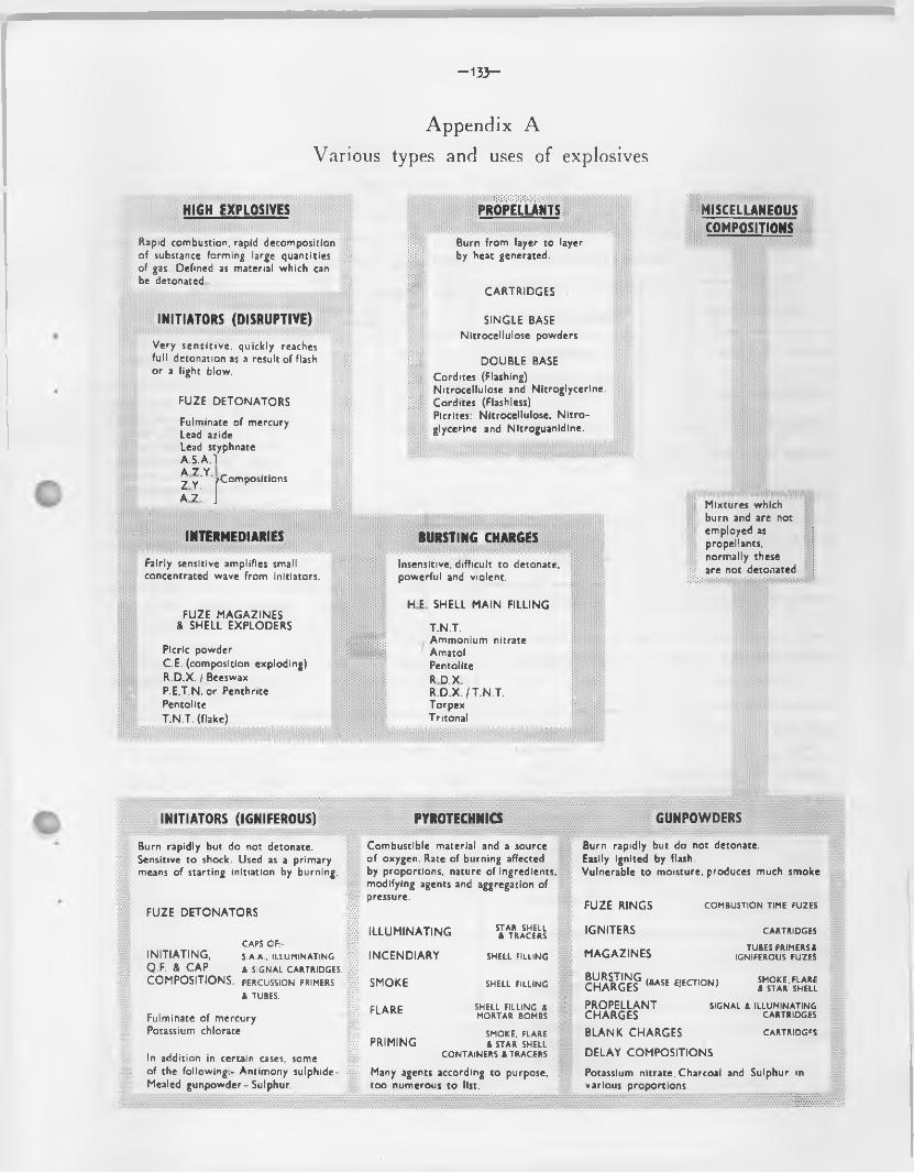
-1 3 3 -
Appendix A
Various types and uses of explosives
HIGH EXPLOSIVES PROPELLANTS
Rapid combustion, rapid decomposition i Burn from layer to layerof substance forming large quantities s: * by heat generated.of gas Defined as material which canbe detonated hi? m
CARTRIDGES
INITIATORS (DISRUPTIVE) SINGLE BASE
Very sensitive, quickly reachesNitrocellulose powders
full detonation as a result of flash S Si DOUBLE BASEor a light blow. j#; Cordites (Flashing)
Nitrocellulose and Nitroglycerine.FUZE DETONATORS iii m Cordites (Flashless)
Fulminate of mercury Lead azide
Picrites: Nitrocellulose. Nitro-glycerine and Nitroguanldine.
Lead styphnateA.S.A.l A Z Y^ y ' '/Compositions
A z' )
INTERMEDIARIES BURSTING CHARGES
Fairly sensitive amplifies small Insensitive, difficult to detonate.concentrated wave from initiators. powerful and violent.
HE SHELL MAIN FILLINGFUZE MAGAZINES
& SHELL EXPLODERS T.N.T.
Picric powder i i i i i i Ammonium nitrate Amatol
C.E. (composition exploding) PentoliteR.D.X. / Beeswax R D.XP.E.T.N. or Penthrite R .D .X ./T.N .T.Pentolite TorpexT.N.T. (flake) Tritonal
MISCELLANEOUSCOMPOSITIONS
1:::
Mixtures which burn and are not employed as propellants, normally these are not detonated
INITIATORS (IGNIFEROUS)
Burn rapidly but do not detonate. Sensitive to shock. Used as a primary means of starting initiation by burning.
FUZE DETONATORS
CAPS OF:-INITIATING, S.A.A., ILLUMINATINGQ.F. & CAP & SIGNAL CARTRIDGES.COMPOSITIONS, percussion primers
& TUBES.
Fulminate of mercury Potassium chlorate
In addition in certain cases, some of the following.- Antimony sulphide- Mealed gunpowder - Sulphur
PYROTECHNICS
Combustible material and a source of oxygen. Rate of burning affected by proportions, nature of ingredients, modifying agents and aggregation of pressure.
ILLUMINATING
INCENDIARY
SMOKE
STAR SHELL & TRACERS
SHELL FILLING
SHELL FILLING
ci a r c SHELL FILLING &rL' ' r,c MORTAR BOMBS
SMOKE, FLARE PRIMING & STAR SHELL
CONTAINERS & TRACERSMany agents according to purpose, too numerous to list.
GUNPOWDERS
Burn rapidly but do not detonate.Easily ignited by flash.Vulnerable to moisture, produces much smoke
FUZE RINGS
IGNITERS
MAGAZINES
BURSTING /b»cc cicrnriMi CHARGES (BASE EJECTION)
COMBUSTION TIME FUZES
CARTRIDGESTUBES PRIMERS&
IGNIFEROUS FUZES
SMOKE, FLARE & STAR SHELL
PROPELLANTCHARGES
SIGNAL & ILLUMINATING CARTRIDGES
BLANK CHARGES cartridges
DELAY COMPOSITIONS
Potassium nitrate.Charcoal and Sulphur in various proportions
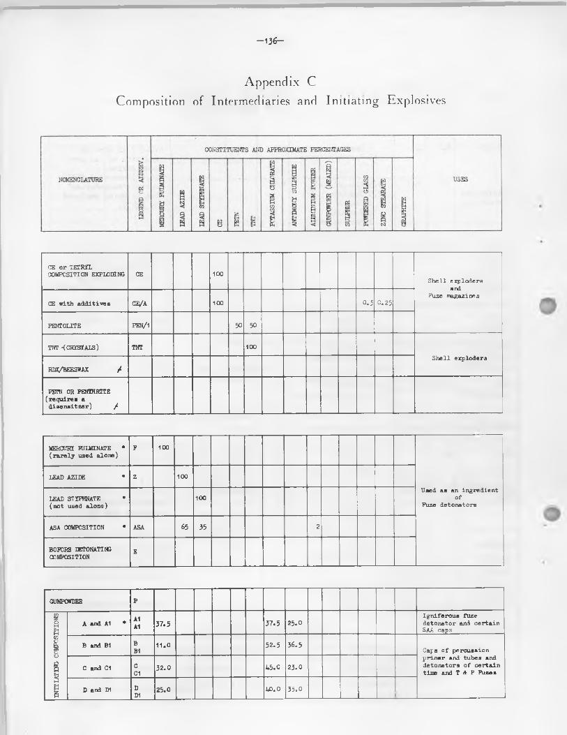
- 1 3 6 -
Appendix C
.Composition of Intermediaries and Initiating Explosives
CE o r TETRYL COMPOSITION EXPLODING CE 100
S h e l l e x p lo d e r s and
Fuze m agazin esCE w ith a d d i t i v e s CE/A 100 0 .5 C. 25
p e n t o l it e PEN/1 30 50
TNT -(CRYSTALS) TNT 100
S h e l l e x p lo d e r s
RDX/BEESWAX /
PE7TN OR PENTHRITE ( r e q u i r e s a
d i s e n s i t z a r ) /■
MERCURY FULMINATE * ( r a r e l y u sed a lo n e )
P 100
U sed as an in g r e d ie n t o f
Fuze d e to n a to r s
LEAD AZIDE * Z 100
LEAD STYPHNATE * (n o t u sed a lo n e )
100
ASA COMPOSITION * ASA 65 35 2
BOPORS EETONATING COMPOSITION
E
GUNPOWDER P
INIT
IAT
ING
CO
MP
OS
ITIO
NS
A and A1 •A1A1 3 7 .5 3 7 .5 2 5 .0
I g n i f e r o u s fu z e d e to n a to r and c e r t a inSAA caps
B and B1 BB1
11 .0 5 2 .5 3 6 .5Caps o f p e r c u s s io n p r im e r and tu b es and d e to n a to r s o f c e r t a in t im e and T A P Fu zes
C and C1 CC1
3 2 .0 4 5 .0 2 3 .0
D a n l D1 DD1
25 .0 LO.O 3 5 .0
-1 3 7 -
NOMENCLATURE
g
CONSTITUENTS AND APPROXIMATE PERCENTAGES
USES
j
19 !
8 ij | j
l
,
c/
c
I
I
oft
|
QF COMPOSITION Q 3 6 .4 5 4 .6 3 .0 3 .0 3 .0Caps o f p e r c u s s io n p r im e rs and c e r t a in SAA 0 b 8 e r . b u l l e t s
Q3 COMPOSITION Q3 54 .0 4 0 .0 6 .0 Caps o f p e r c u s s io n p r im e rs
FULMINATE COMPOSITION 8 0 .0 2 0 .0 L a rg e d e to n a to r s
I
0
E1 E1 1 9 .0 3 3 .4 4 2 .8 2 .4 2 .4Caps o f SAA and p e r c u s s io n tu b es
PI P I 2 8 .0 4 1 .0 3 1 .0
C e r t a in SAA CapsG1 G1 2 7 .0 3 2 .0 4 1 .0
VH2 VH2BARIUM NITRATE 3 9 .0 ANTIMONY SULFKTDE 5 .0 COMPOSITION RD 1302 3 8 .0 I£AD PEROXIDE 5 .0 CALCIUM S U IC ID E 1 1 .0 TETRAZINE 2 .0
* T h ese c o m p o s it io n s may b e u sed i n c o n p o s ite f i l l i n g s o f fu z e d e to n a to r s . (S e e p a ra g ra p h s 107 t o 110)
/ P r o p o r t io n s may v a r y a c c o rd in g t o use.
The reason fo r the inclusion o f the various ingredients is as fo llows
Aluminium Antimony sulphide Glas s-powdered Gunpowder (mealed) Mercury fulminate Potassium chlorate Sulphur Ware
increases heat and flame prolongs the flame e ffe c t induces fr ic t io ndiminishes the violence o f the explosion increases the sen s it iv ity o f the composition increases the heat o f the explosion diminishes the violence o f the explosion used as dessensitizer
Notes:-
(1 ) "A” and "A.1* e tc . , mixtures are iden tica l in chemical composition but d i f fe ra g r is t s ize o f potassium chlorate and antimony sulphide; the former mixture being the coarser. For A, B, C and D a l l the chlorate/sulphide must be retained on a 170 mesh sieve. For A1, B1, C1 and D1 approx. 75 per cent, o f the chlorate is retained on a 170 mesh sieve and only 20 per cent, o f the antimony sulphide,A, B, C AND D are a lleged to be the more sensitive .
(2) "A" mixture was found early in the Second World War to be too sensitive fo r usein certain primers, and i t was replaced by the older Q.F. composition. The la t te r , however, is more lia b le to give m isfires and hangfires than is "A" mixture, and Q3 composition was tr ied in l ie u o f Q.F.
-1 3 8 -
Appendix D
Code indicating High Explosive Fillings with
Composition and Percentages of Ingredients
ItemNo. P il l in g Conposition and percentage o f
ingredients
Code le t te rs and numbers sten cilled on shoulder or body
1 TNT TNT (grade 1) TNT 1
TNT (grade 2) TNT 2
TNT contaminated with up to RDX TOT 3
9395 TNT (grade 1)795 Beeswax
tnt/bwx. 1
2 Amatol AT# Am. N it.6Cf£ TNT (grade 1)
AML. 1
50^ Am. N it.5095 TNT (grade 1)
AML. 2
60?S Am. N it .4g£ TNT (grade 1)
AML. 3
7Cfi Am. N it.3095 TNT (grade 1)
AMU 4-
72^ Am. N it.2 % TNT (grade 1)
AMU 5
8C$ Am. N it.20 b TNT (grade 1)
AMU 6
3 PE. 1 88.395 RDX11.795 PE o i l (type 1)
PE. 1
PE. 2 88.395 RDX11.795 EE o i l (type 2)
PE. 2
IE. 3 87.755 RDX10.595 Shell Mex o i l 119 0 .($ Lecith in 1.295 Carbon black
PE. 3
PE.3A 87.795 RDX6.2# Shell Hex O il 119 4.195 Para ffin liqu id Gd.1 0. % le c ith in
up to 1.595 carbon black added.
PE.3A
—139—
ItemNo. P il l in g Conposition and percentage o f
ingredients
Code le tte rs and numbers stencilled on shoulder or body
4 RDX 91$ RDX(grade 1, 1A, (B ) 1, (B) 1A)
9% Beeswax
rdx/bwx. 1
91% RDX(grade 2, (B ) 2) 9% Beeswax
RDX/BWX. 2
5 rdx/fwx 86$ RDX Grade 1 11$ Para ffin wax
RDX/PWX.1
6 RDX/TOT 60$ RDX(grade 1, 1A, (B) 1, (B) 1A) 40$ TNT (grade 1)
RDX/TOT. 1
6C$ RDX(grade 2. (B) 2) 40$ TNT (grade 1)
rdx/tnt. 2
55$ RDX(grade 1. 1A, (B ) 1, (B ) 1A) 45$ TNT (grade 1)
RDX/TNT. 3
59$ RDX(grade 2. (B ) 2) 45$ TNT (grade 1)
RDX/TNT. 4
50$ RDX(grade 1, 1A, (B) 1, (B ) 1A) 50$ TNT (grade 1)
RDX/TOT. 5
5Q$ RDX(grade 2, (B ) 2) 50$ TOT (grade 1)
RDX/TNT. 6
40$ RDX(grade 1 1A, (B) 1, (B ) 1A) 60$ TNT (grade 1)
RDX/TNT. 7
43$ RDX(grade 2, (B ) 2) 60$ TNT (grade 1)
RDX/TOT. 8
7 rdx/wax/al 67.5$ RDX (grade 1 or 1A) 12.5$ Para ffin wax 20$ Aluminium
RDX/AL.1
66$ RDX (grade 1 or 1A) 12$ Para ffin wax 2C$ Aluminium
RDX/AL.2
c
—i40—
Appendix E
Details of Ammunition authorized for
Field Branch Artillery Equipments
1. The fo llow ing are the approved equipments fo r F ield Branch A r t i l le r y
Q.F. 25 pr.B.L. 4.5 inch gun B.L, 5.5 inch gun B.L. 7.2 inch howitzer
With the exception o f the 25 pr. whioh i s Q.F. separate loading, a l l ammunition i s o f the B.L.type.
For the description and deta ils o f M.L. 4.2 inch mortar ammunition which i s also equipment o f F ie ld Branch A r t i l le r y units see Chapter 11.
Part i. Q.F. 25-PR. Gun Ammunition
2. Ammunition o f the fo llow ing types is approved fo r th is equipment, which i s the standard guiy*" howitzer fo r F ie ld Branch A r t i l l e iy : -
PROJECTILES
Shell H.E. streamline Shell streamline, B.E. screening smoke Shell streamline, B.E. coloured smoke
("blue, green, red, yellow)Shell streamline B.E. incendiaryShell f la r e , T .R ., B.E. (red, green, yellow )Shell starShell d r i l lShot A.P.Shot A.P.C.Shot practice Shot d r i l l Shot paperP ro je c t ile , p ractice , streamline
CARTRIDGES
NormalSuperchargeIntermediate charge incrementSupercharge incrementPaper shotBlankD r il l
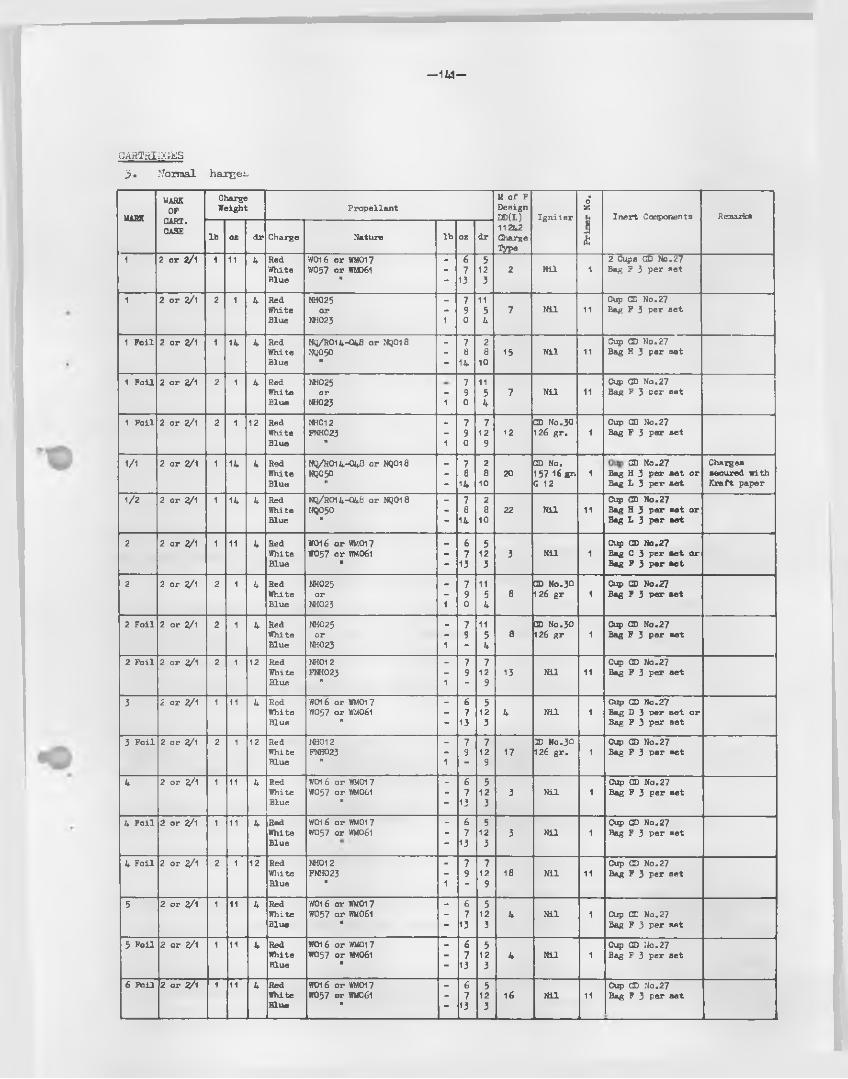
- 1 W -
CART.HIIX ES j>. Normal harcet.
MARK
MARKOF
CART.CASE
ChargeW eight P r o p e l la n t
M o f F D esign DD(L) I g n i t e r
Pri
me
r N
o.
I n e r t Components Remarks
lb oz d r Charge N ature lb oz d r11242ChargeType
1 2 o r 2/1 1 11 4 Red W016 o r WM017 - 6 5 2 Cups CD N o .27W hite W057 o r 1R061 - 7 12 2 N i l I Bag F 3 p e r s e tB lu e it - 13 3
1 2 o r 2/1 2 1 4 Red NH025 - 7 11 Cup CD N o .27W hite o r - 9 5 7 N i l 11 Bag F 3 p e r s e tB lue NH023 1 0 4
1 F o i l 2 o r 2/1 1 14 4 Red NQ/R014-048 o r NQ018 _ 7 2 Cup CD N o .27W hite 1^050 - 8 8 15 N i l 11 Bag H 3 p e r s e tB lue It
- 14 10
1 F o i l 2 o r 2/1 2 1 4 Red NH025 7 11 Ci?> CD N o .27W hite o r - 9 5 7 N i l 11 Bag F 3 u e r s e tB lue NH023 1 0 4
1 F o i l 2 o r 2/1 2 1 12 Red NH012 - 7 7 CD N o .30 Cup CD N o .27W hite FNH023 - 9 12 12 126 g r . 1 Bag F 3 p e r s e tB lu e " 1 0 9
1/1 2 o r 2/1 1 14 4 Red NQ/ROI4 -0 48 o r NQ018 - 7 2 CD No. CD N o .27 ChargesW hite NQ050 - 8 8 20 157 16 gr. 1 Bag H 3 p e r s e t o r secu red w ithB lue it - 14 10 G 12 Bag L 3 p e r s e t K r a f t p ap er
1/2 2 o r 2/1 1 14 4 Red NQ/R014-048 o r NQ018 - 7 2 Cup CD N o .27W hite NQ050 - 8 8 22 N i l 11 Bag H 3 p e r s e t o rB lue H
“ 14 10 Bag L 3 p e r s e t
2 2 o r 2/1 1 11 4 Red W016 o r WM017 _ 6 5 Cup CD N o .27W hite WO57 o r WM061 - 7 12 3 N i l 1 Bag C 3 p e r s e t o rB lue H - 13 3 Bag F 3 p e r s e t
2 2 o r 2/1 2 1 4 Red NH025 _ 7 11 CD No.30 Cup CD N o .27W h ite o r - 9 5 8 126 g r 1 Bag F 3 P « r s e tB lue NH023 1 0 4
2 F o i l 2 o r 2/1 2 1 4 Red NH025 - 7 11 CD No .30 Cup CD N o .27W h ite o r - 9 5 8 26 g r 1 Bag F 3 p e r s e tB lue NH023 1 - 4
2 F o i l 2 o r 2/1 2 1 12 Red MH012 - 7 7 Cup CD N o .27W hite FNH023 - 9 12 13 N i l 11 Bag F 3 p e r s e tB lue H 1 - 9
3 2 o r 2/1 1 11 4 Red W016 o r WMOI7 - 6 5 Cup CD N o .27W h ite W037 o r WM061 - 7 12 4 N i l 1 Bag D 3 n e r s e t o rB lue H - 13 3 Bag F 3 p e r s e t
3 F o i l 2 o r 2/1 2 1 12 Red NH012 - 7 7 2D No .30 Cup CD N o .27W hite FNH023 - 9 12 17 126 g r . 1 Bag F 3 p e r a c tB lue ” 1 - 9
4 2 o r 2/1 1 11 4 Red W0 16 o r WMOI 7 - 6 5 Cup CD N o .27W hite W057 o r WM061 - 7 12 3 N i l 1 Bag F 3 p e r s e tB lue M - 13 3
4 F o i l 2 o r 2/1 1 11 4 Red W016 o r WM017 - 6 5 Cup CD N o .27W h ite W057 o r WM061 - 7 12 3 N i l 1 Bag F 3 p e r s e tB lue - 13 3
4 F o i l 2 o r 2/1 2 1 12 Red NH012 - 7 7 Cup CD N o .27W h ite FNH023 - 9 12 18 N i l 11 Bag F 3 p e r s e tB lue It 1 - 9
5 2 o r 2/1 1 11 4 Red W016 o r WMOI7 - 6 5W hite W057 o r WM061 - 7 12 4 N i l 1 Cup CD N o .27B lue It - 13 3 Bag F 3 p e r s e t
5 F o i l 2 o r 2/1 1 11 4 Red W016 o r WM017 _ 6 5 Cup CD N o .27W hite WO57 o r WM061 - 7 12 4 N i l 1 Bag F 3 p e r s e tB lue It
“ 13 3
6 F o i l 2 o r 2/1 1 11 4 Red W016 o r WMOI 7 - 6 5 Cup CD N o .27W hite W057 o r WM061 - 7 12 16 N i l 11 Bag F 3 p e r s e tB lu e It - 13 3

—142—
dormal charges (con tin u ed )
MARK
MARKOF
CART.CASE
ChargeW eigh t
P r o p e l la n tM o f F D es ign DD(L) 11242 Charge■type
I g n i t e r
Pri
me
r N
o.
I n e r t Components Remarks
lb O Z d r Charge i N atu re lb oz d r
7 F o i l 2 o r 2 / 1 1 11 4 RedW hiteB lue
W016 o r WMC1 7 W057 o r WM361
n
67
13
512
3
19 CD No.30 126 g r .
1 Cup CD N o .27 Bag F 3 p e r s e t
N .Am erican p ro d u c tio n . Charges s e c u r ed w ith K r a f t paper
4 . Super c h a r g e s
1 2 o r 3/1 2 8 0 - WT206-100 o r WM/T211-100
2 8 0 5 N i l 1 Cup CD N o .26 l\
)A l l ch argesco n ta inf o i l
1 2 o r 2/1 2 9 1/4- - SC/T 198-100 2 9 14 9 N i l 1 Cup CD N o .26 j
1 2 o r 2/1 2 13 8 - NO/S1A4-0ID 2 13 8 10 N i l 11 Cup CD N o .26 j
1 2 o r 2/1 2 13 8 - NCi/S134-040 2 13 8 14 N i l 11 Cup CD N o .26 >
5 . S u p e r c f i a r g e i n c r e m e n t s
1 - - - - WM061 - 4 8 \ In c e l l u l o i d c o n ta in e rF o r f i r i n g w ith 20 l b A .P . sh o t o n ly
1 - - - - NQ/S13A-OAO - 5 8
6. In te irn ea i ..te charge increm ent
1 _ . . . NQ/R014-048 4 0 I n cam bric bag " J H
. . .F o r use w ith ch a rges 1 and 2 - Norm al ch a rges o n ly .
7. Cartridges, blank - The marks 1 and 4 are the normal service designs used for both saluting and training purposes. The marks 2 and 3* however, are for special purposes, i . e . the Mk. 2 fo r saluting purposes only for Gibraltar, the Mk. 3 fo r saluting purposes only for Dover.
The mark 1 cartridges consists o f 1 lb . No. 1 primer.The mark 2 cartridges consists o f 8 oz. No. 1 primer.The mark 3 cartridges consists o f 2 lb . No. 1 primer.The mark 4 cartridges consists o f 1 lb . No. 9 primer.
gunpowder G12 in s ilk cloth bag in conjunction with a
gunpowder G12 in s ilk cloth bag in conjunction with a
gunpowder G12 in s ilk cloth bag in conjunction with a
4 oz. cordite WM.017 in bundle in conjunction with a
IflJZES8. A l l H.E. shell are normally issued fuzed, nose fuzed shell with either No. 117, or 213 fuzes
and base fuzed shell with L15 fuzes. Exceptions are H.E. shell f i l le d to code L7 (M. o f P. designs DD(L) 18851 and D2(L)554/GF/229) aid. those issued specifica lly fo r use with No. 213 fuzes. H.E. shell f i l le d to code L7 are issued plugged, fo r use as follows:-
(a ) Those fitted with Plug, P.H. 2 inch No. 13 have the top exploder assembled in position and are known as "universal cavity" shell i . e . , they are suitable for use with percussion, time or V.T. fuzes v iz . No. 117, 213 or T97.
(b) Those fit ted with plug, P.H. 2 inch No. 29 have no top exploder present and are for use with V.T. fuzes only v iz . T97.
I t is important, therefore, that these two types, which are d is tin ctly marked, be accounted for and stored separately.
A ll screening and coloured smoke, fla re , incendiary and star shell are issued fuzed No. 221Bfuzes.
IRIMER59. Nos. 1, 9 and 11 Primers, percussion, Q.P. cartridges are approved fo r vise. Since the type o f
primer used depends on a number o f factors, such as the nature o f propellant, arrangement o f the charge and the presence or otherwise o f an ig n ite r , reprimering, when necessary owing to m isfires, e tc . , should be carried out with primers o f the same type though not necessarily o f the same mark.
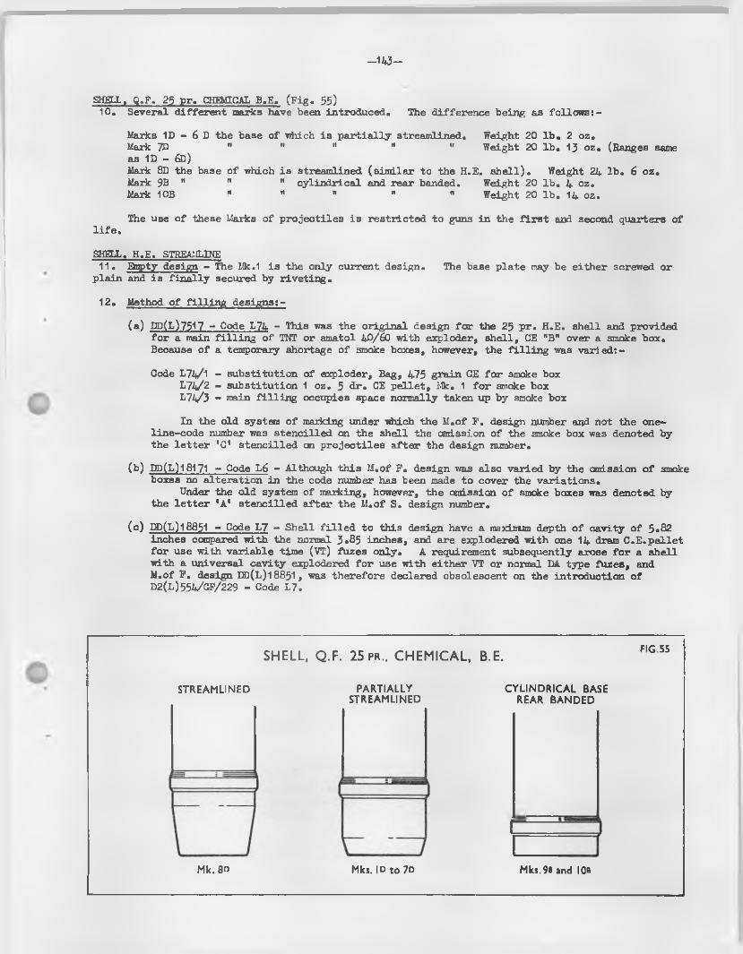
—143—
SHELL, Q.F. 25 pr. CHEMICAL B.E. (F ig . 55)10. Several d iffe ren t marks have been introduced. The d ifference being as fo llow s:-
Marks 1D - 6 D the base o f which is p a r t ia lly streamlined. Weight 20 lb . 2 oz.Mark 7D " " M " " Weight 20 lb . 13 oz. (Ranges sameas 1D - 6D)Mark 8D the base o f which is streamlined (s im ila r to the H.E. s h e l l ) . Weight 24 lb . 6 oz.Mark 9B " " " cy lind rica l and rear banded. Weight 20 lb . 4 oz.Mark 10B " " " M " Weight 20 lb . 14 oz.
The use o f these Marks o f p ro je c tiles is res tr ic ted to guns in the f i r s t and second quarters o fl i f e .
SHELL. H.E. STREAMLINE11. Snpty design - The Mk.1 is the only current design. The base p la te may be either screwed or
plain and is f in a lly secured by r ive tin g .
12. Method o f f i l l in g designs:-
(a ) DP(L)7517 - Code L74 - This was the orig ina l design fo r the 25 p r. H.E. shell and provided fo r a main f i l l i n g o f TNT or amatol 4^/60 with exploder, sh e ll, CE "B" over a smoke box. Because o f a temporary shortage o f smoke boxes, however, the f i l l i n g was varied :-
Code L74/1 “ substitution o f exploder, Bag, 475 grain GE fo r smoke box L71/2 - substitution 1 oz. 5 d r. CE p e lle t , Mk. 1 fo r smoke box L74/3 - main f i l l i n g occupies space normally taken up by smoke box
In the old system o f marking under which the M.of F . design number and not the one- line-code number was sten cilled on the shell the omission o f the smoke box was denoted by the le t t e r 'C* s ten c illed on p ro je c t ile s a fte r the design number.
(b ) DD(L)18171 - Code L6 - Although th is M.of F . design was also varied by the omission o f smoke boxes no a ltera tion in the code number has been made to cover the variations.
Under the old system o f marking, however, the omission o f smoke boxes was denoted by the le t t e r 'A ' s ten c illed a fte r the M.of S. design number.
(c ) DP(L)18851 - Code L7 - Shell f i l l e d to th is design have a maximum depth o f cavity o f 5*82 inches compared with the normal 3.85 inches, and are explodered with one 14 dram C .E .pe llet fo r use with variab le time (VT) fuzes only. A requirement subsequently arose fo r a sh ell with a universal cav ity explodered fo r use with e ith er VT or normal DA type fuzes, and M.of F. design DD(L)18851, was therefore declared obsolescent on the introduction o f D2(L)554/GF/229 - Code L7.
SHELL, Q.F. 25 PR.. CHEMICAL, B.E. FIG.55
STREAMLINED PARTIALLYSTREAMLINED CYLINDRICAL BASE REAR BANDED
Mks. ID to 7D Mks.9B and I ObMk. 80
- 1 4 V
(d ) D2(L)534/GF/229 - Code L7 - This i s the current M.of P . design and is known as the "universal cav ity " type o f f i l l in g in that fuzes with short magazines e .g . 117 and 119 may be used d irect without a lteration o f the exploder system, while VT fuzes (having a grea ter intrusion) may be used only a fte r removal o f the 6 oz. CE top exploder.
Shell f i l l e d to this design and explodered fo r optional use o f VT fuzes are plugged with plug, fuze-hole, 2 inch, No. 13* the top o f which is painted blue to denote the presence o f the top exploder and are not provided with a fix in g screw hole.
37,000 3h e ll f i l l e d to th is design have been incorrectly s ten cilled "L36" instead o f "L7". No action w i l l be taken to amend the s ten c illin g u ntil the sh ell are due fo r repainting, at which time the shell markings w i l l be r e c t if ie d .
SHELL, STREAMLINE. B,E. SCREENING SMOKE13* Enpty design - Existing marks are sim ilar in design, d if fe r in g mainly in the design o f driving
band and in the presence or absence o f a separate screwed head (nose bush), v i z : -
Mk.1 - No separate headMk.2 - P itted with separate headMk.3 - D iffe rs from Mk.2 p rin c ipa lly in having a cone seating fo r the separate head.Mk.4. - Generally sim ilar to the Mk. 1 but is f i t te d with a driving band to design DD(L)64-87/7,
is s lig h t ly heavier and nay have a normal ogive or a separate head.Me.5 - Generally sim ilar to Mk.2 d if fe r in g p rin c ipa lly in being f i t t e d with a driving band to
design DD(L)6487/7 and in the weight.Mk.6 - There are two empty designs fo r the Mk. 6 sh e ll, DD(L)12584. and DD(L)1934-9, Shell
DD(L) 12584. have a separate head, while those to DD(L) 1934-9 may have a separate head o r a normal ogive. Both designs are f i t t e d with a driving band to DD(L) 6487/7.
With e f fe c t from February, 1957 a new pattern base (SX 588) which is manufactured with a reduced thread area to fa c i l i t a t e e jection o f containers w i l l supersede marks 1 and 1/1 No. 2 bases. The No.2 bases f i t t e d to ex isting stocks o f eupty sh e ll w i l l be modified to the new pattern (SX 588) p r io r to the empty sh ell being f i l l e d .
(a ) DD(L)7223B/1 Mk.1 and DD(L)94-68 Mk.2 - A copper disc 0.05 inch thick is assembled between the la s t smoke container and the closing base, millboard d iscs, as required, being inserted above the copper disc to prevent movement o f the smoke containers.
The base p la te fo r the empty Mks. 1 and 2 sh e ll, which has a screw-threaded metal ringsweated to i t , i s secured to the base o f the shell by means o f a fix in g screw. The thicknesso f the base p la te i s 0,83 inch.
(b ) DD(L)11361 Mk.3 “ Bawe, sh e ll, No.2, Mks. 1 or 1/1 is used. I t is 0.87 inch thick and a copper disc i s not, therefore, required. The base is screw-threaded but i s not secured with a fix in g screw.
(c ) DD(L)12582 Mk.4- - Base, sh e ll, No. 1 Mk. 1 i s used. I t is generally sim ilar to the base fo rthe mark 1 and 2 empty shell in that i t is O.83 inch th ick, has a screw-threaded metal lin gsweated on, i s used in conjunction with a copper disc and millboard d iscs, and i s secured by means o f a fix in g screw.
(d ) DD(L)12583 Hk.5 - Base, sh e ll, Nos. 1 or 2 may be used.
(e ) DD(L) 12584. and DD(L)l934-9 Mk.6 - Shell to design DD(L)12584- are f it te d with Base, sh e ll, No.2 Mk.1 but sh ell to design DD(L)1934-9 are f i t t e d with Base, sh e ll, No.2, Mk.1/1.
14. Method o f f i l l i n g designs - The fo llow ing method o f f i l l in g designs are used:-
DD(L)7223BDD(l ) i 0681 (Code L33)D2(L)1528/GF/135 (Code L35)
The above designs d i f fe r in minor d e ta il only and are associated with the various marks o f shell described above. A l l three designs provide fo r three containers, smoke, No.3 M.of F . design D2(L)1528/GF/135 - L33 i s current and supersedes DD(L)7223B and DD(L)10681.
-1 4 5 -
SHETL, STPEIAMLINE, B.E. COLOURED S..QKE (Blue, .Green, Red and Yellow)15« Empty designs - Coloured smoke shell are o f the same empty design as screening smoke sh ell but
when f i l l e d , a separate series o f marks is a llo tted , v i z : -
Empty Mks. 1 , 2 and 3 screening smoke sh e ll, when f i l l e d coloured smoke become Uk. 1 shell Empty Mks, 4, 5 and 6 screening smoke sh e ll, when f i l l e d coloured smoke become Mk, 2 shell
Empty mark numbers are stamped and f i l l e d marks are stencilled on the shell body.
16. Method o f f i l l in g designs - Both Iflc, 1 and 2 shell are f i l l e d to the same designs as the screening smoke sh ell except that the smoke containers are charged w ith coloured smoke compositions,
M.of P , design D2(L)152§/GF/135 supersedes DD(L)10681 arkl DD(L)17625. As the differences are in minor d e ta il only, however, a l l three M,of F, designs have been a llo tte d code L33/4*
17« Container, smoke - There are two variations o f stee l container, smoke, No,3 mark 2, v i z , , container, smoke, B.E. ( fo r use with streamline B.E. screening smoke sh e ll) the central tube o f which is not f i t t e d with s tee l plugs, and container, coloured smoke ( f o r use with coloured smoke sh e ll) the central tube o f -which i s f i t te d w ith a d r ille d s tee l plug at each end,
SHELL, FLARE, T,R, B.E, (Target Recognition, Base E jection )18, Rnpty design - The em pty sh e ll i s o f the same design as the streamline B.E. Mk.6 screening
smoke sh e ll, although the word "streamline" has been omitted from the nomenclature,
19* Method o f f i l l i n g design - Shell to th is design (D2(L)149/GF/193 - Code 145/3) are f it te d with three containers f i l l e d SR f la r e composition which may be one o f three colours i . e . red, green or yellow . Containers o f d iffe ren t colour composition are not mixed in the same sh e ll.
SHELL, STREAMLINE. B.E, INCENDIARY20. Empty design - The empty sh e ll i s the same design as the streamline B.E. Mk.6 screening smoke
sh e ll.
21, Method o f f i l l i n g design - The shell are f i l l e d to design DD(L)11182. E ither o f two types o fs tee l container may be used, v i z . , container No.1 or container No.10. Those sh e ll f i l l e d withcontainer No. 1 are a llo tted code L33/8 and those f i l l e d with container No. 1C - L33/9*
STAR SHELL22. Empty design - The empty sh e ll i s manufactured to design BD(L)17892+/1 • I t i s not streamlined
although the portion below the driving band is s lig h t ly tapered. This is a base e jection shell although the abbreviation "B.E." has been omitted from the nomenclature,
23* Method o f f i l l i n g design - The shell is f i l l e d to design DD(L)17894 (Code L35). This M.of P. design i s typ ica l fo r a l l star sh e ll. The parachute has a diameter o f 18 inches and the colour o f the star is white.
SHOT A.P.C.24. The mark 7 design i s sim ilar to the shot A.P. Mk.6, but is f i t t e d with a penetrative cap which
is monolized to the shot.
SHOT PRACTICE25. The mark 1 practice shot i s an exception to the general po licy being made o f mild stee l
instead o f cast iron . Marks 1 and 2 shot are f i t t e d with internal tracer No. 2 mark 7, a l l other shot being recessed to receive an in tegra l tracer f i l l in g which may produce a red or white trace according to the method o f f i l l in g design.
Appendix EPart 2. B.L. 4 .5 -inch Gun Ammunition
26, Ammunition o f the fo llow ing types i s approved fo r th is equipment, which is the standard medium gun fo r F ie ld Branch A r t i l le r y : -
PROJECTILES CARTRIDGES
F irs t chargeThird charge (comprises charge 2 and 3 )BlankD r il l
Shell, H.E. streamline Shell d r i l l
—146—
CARTRIDGES27• There are two main types o f cartridges, these being:-
Charge 1 Charge 3
28* Charge one:-
(a ) 2 lb . 15 oa» cord ite SC.048, Mk.1, 2 lb , 15 oz. cord ite W.057. Mk.1. 2 lb .13 oz.cord ite WI.U051 Mk.1 - These cartridges d i f fe r only in the type o f propellant used. The cartridge i s o f the stalk type and is f i t t e d with a 1 oz. "A" ig n ite r at the la rge r end.
(b) 2 lb . 13 oz. cord ite WM.061. Mk.2 (il lu s tra te d in P ig . 7 ) - This d if fe r s from the Hk.1 cartridge in being cy lind rica l in shape and in being f i t t e d with a 1 oz. G12 gunpowder ig n ite r .
(c ) 3 lb . 1 oz. cord ite HQ.030 Mk.1 - This cartridge i s o f the stalk type. I t i s f i t t e d with two ign ite rs ; a 1 oz. "A" being f i t t e d to the rear o f the la rger diameter section , the other o f 1.1/2 oz. G.12 gunpowder is ring shaped and is f i t te d to the front end o f th is section.
(d ) 3 lb . 1 oz. cord ite NQ.050 Mk.2 - This d if fe rs from the Mk.1 cartridge in being cy lind rica l in shape.
29. Charge th ree:-
(a ) 9 lb . 2 oz. cord ite SC,109 Mk.1 f o i l , 9 lb . 2 oz. cord ite W.124 Mk.1 f o i l , 9 lb . 2 oz. cord ite WH.124, i.Qc.1 f o i l , 9 lb . 2 oz. cord ite WM.130 Mk.1 f o i l - The cartridges d i f fe r only in the type o f propellant used. They consist o f a 6 lb , 7 oz. charge two portions f i t t e d w ith a 1 oz. HB" ig n ite r , and a 2 lb . 11 oz. charge three increment. Both portions are cy lin d rica l in shape and lead or t in f o i l is incorporated at the inner end o f each portion .
(b ) 10 lb . 9 oz. cord ite N/S 164-048. Mk. 1 f o i l ( i l lu s tra te d in P ig . 7 ) - This consists o f a 7 lb . 9 oz. charge two portion and a 3 lb . charge three increment. Both portions are cy lin d rica l in shape. The charge two portion is f i t t e d with two ign ite rs , one a 1 oz. G12 gunpowder and the other a 2 oz. "A". Lead or t in f o i l is incorporated in the outer end o f the charge three increment, and also wrapped around the propellant o f the charge two portion.
FUZES30. H.E. sh ell are issued plugged being f i t t e d with plug, P.H. 2 inch No. 13 . The top exploder is
assembled in position , and the shell are suitable fo r use with e ith er No.117, or 213 fuzes.
IGNITERS. AUXILIARY31. Cartridges, B.L. ign iters auxiliary "CM are issued fo r use with cartridges in the event o f the
ex isting f it te d ign ite rs becoming damp. They consist o f two red worsted cloth discs sewn together by two rings o f stitch ing , and sewn across to form f iv e pa ra lle l compartments which are f i t t e d with 1 oz. gunpowder G12. A drawstring o f s ilk or worsted webbing is threaded around the edge o f the ig n ite rto form a sk irt and to secure the ig n ite r to the cartridges.
SHELL H.E. STREAMLINE32. Bnpty design - Only one mark o f H.E. sh e ll was produced fo r th is equipment• The shell is
manufactured to design BD(L)8102 and is f i t t e d w ith a driving band to design DD(L) 6817/2. The design covers two a ltern ative heads, one being in the form o f a mild s tee l bush. The base p la te may be e ith er screwed or p la in and is f in a l ly secured by r iv e tin g .
33 • Method o f f i l l i n g designs - The follow ing method o f f i l l in g designs are used: -
DD(L}7342 DD(L)17865 (Code L1/1 or L1/3)DD(L)7343C DD(L)19506 (Code L3)DD(L)11561 DD(L)869/GF/235 (Code L6)Dd(l ) 16879 (Code L1 or L1/2) D2(L)903/GF/317 (Code L1/2)
In 1944 i t was decided to modify a l l B.L. 4 .5 inch H.E. shell f i t t e d with plug, fuze-hole, 2 iixii No.13* This m odification consisted o f f i t t in g a top exploder together with a plug, fuze-hole, 2 inch No.13 or a converted plug, fuze-hole, 2 inch No.3 . The conversion o f the la t t e r plug consisted o f cutting o f f the shank, smoothing the face o f the boss and chamfering i t s edge. This converted plug is s lig h t ly deeper than the plug No.13 but th is d ifference was considered to be acceptable. The top o f both types o f plug was painted blue. No attempt was made to a lte r the M.of P . design number sten cilled on the shell as the blue plug indicates the presence o f a top exploder.
- 1 4 7 -
34• Surroundings and toppings - TNT surrounds and toppings are used with sh ell f i l l e d amatol. TNT toppings are used with KDX/TNT f i l l in g s .
33• Exploder containers - A l l amatol f i l l e d sh ell enploy a s tee l exploder container. Shell filled , to design DD(L)l950^ are f i t t e d with a container, s tee l, No.4, a l l other amatol f i l l e d shell being f i t t e d with a container, s te e l, No.1. A container, s tee l, No.1 is also used with shell f i l l e d TNT to DD(L) 17865.
36. Smoke boxes - Shell f i t t e d with red phosphorus smoke boxes have been found to be l ia b le to phosphoric acid exudation due to moisture entering badly sealed boxes. A ll red phosphorus smoke boxes are, therefore, being replaced by TNT/AL smoke p e lle ts , as smoke production i s s t i l l an observation requirement fo r F ie ld Branch A r t i l le r y .
TUBES37. Tubes, percussion, S.A. cartridge are approved fo r use w ith this equipment.
Appendix EPart 3. B.L. 5 .5 -inch Gun Ammunition
38. Anmunition o f the fo llow ing types i s approved guVhowitzer fo r F ie ld Branch A r t i l le r y :-
PROJECTILES
Shell, H.E. streamline (100 lb . )Shell, H.E. streamline, 80 lb .Shell, chemical B.E. streamline Shell, incendiary B.E.Shell, B.E. screening smoke Shell B.E. coloured smoke (blue, green, red, yellow )Shell f la re , T .R ., B.E., (red , green) Shell d r i l l Shot paper
fo r th is equipment, which is the standard medium
CARTRIDGES
Charge two(comprises charge 1 and 2)Charge four(comprises charge 3 and 4 ) Super-charge ( fo r use with 80 lb . sh e ll only)
(previously designated " fu l l charge")Charge fo r paper shotBlankD r i l l
CARTRIDGES39. There are four main types o f cartridges, these being:-
Charge 2 Charge 4Super-charge ( fo r use with 80 lb . sh ell only) Paper shot cartridges
40. Charge two:-
(a ) 4 lb . 4 oz. cord ite W.O57, Mk.1, 4 lb . 4 oz. cord ite WM.061, Mk.1 - The cartridges d i f fe r only in the type o f propellant used. They consist o f a 2 lb . 10 oz. 8 dr. charge one portion f it te d with a 2 oz. "C" ig n ite r and a 1 lb . 9 oz. 8 dr. charge two increment.The charge one portion is o f the stalk type while the increment is a f la t bag which is wrapped around and secured to the sta lk .
(b ) 4 lb . 4 oz. cord ite WM.061. Mk.3 - This is in two jjortions, which although o f the same weight as the Mk.1 cartridge, are cy lin d rica l in shape. The charge one portion is f i t te d with a 2 oz. G12 gunpowder ig n ite r at one end. The outer end o f the charge two increment is f i t te d with a l i f t in g becket.
(c ) 4 lb . 12 oz. cord ite NQ.050, Mk.1 - This is in two portions, cy lin d rica l in shape, charge one being o f 2 lb . 15 oz. and charge two increment o f 1 lb . 13 oz. The charge one portion is f i t t e d with two ign iters i . e . , a 1 os. "D" and a 1 oz. G12 gunpowder ig n ite r0
(d ) 3 lb , NH.025. Mk.1 - This consists o f a 3 lb . 1 oz. stalk type charge one and a 1 lb .15 oz. charge two increment in the shape o f a f la t bag which is curved and secured by t ie s around the stalk o f the other portion . The charge one portion is f i t t e d with a1 oz. "C" or G12 gunpowder ig n ite r .
(e ) 3 lb . FNH.023 Mk.1 - This consists o f a 3 lb . 5 oz. stalk type charge one portion ani a2 lb . charge two f la t increment. The charge one portion is f i t t e d with a 1 oz. G12gunpowder ig n ite r .
— 14&-
( f ) 5 lb . 5 Q2« FNH.023. Nk.2 (il lu s tra te d in P ig* 8 ) - This consists o f a 3 18. 3 oz. charge one portion and a 2 lb . 2 oz. charge two increment. The charge one portion is f i t t e d with a 1 oz. G12 gunpowder ig n ite r .
41 • Charge four:-
(a ) 9 lb . 2 oz. cord ite W.104» I-flc.1, 9 lb . 2 oz. cord ite 741.109. I3c»1 f o i l - These cartridges consist o f a 6 lb . 10 oz. 8 d r. charge three portion and a 2 lb . 7 oz. 8 dr. charge four increment. These are both cy lin d rica l in shape. The charge three portion is f i t t e d with a 1 oz. "C" ig n ite r . Lead or t in f o i l discs are positioned in the inner end o f the charge four increment.
(b ) 9 lb . 13 oz. cord ite NQ/S 164-048 i.flc.1 f o i l ( illu s tra te d in P ig . 8 ) - This consists o f a ? lb . 3 oz. charge three "portion and a 2 lb . 10 oz. charge four increment. The charge three portion is f i t t e d with two ign ite rs , a 2 oz. G12 gunpowder at one end and a 1 oz. "C" at the other end. Lead or t in f o i l is positioned in the outer end o f the increment. Both portions are cy lin d rica l in shape.
(c ) 10 lb . 14 oz. FNHP.038, Mk.1 - This consists o f an 8 lb . charge three portion and a 2 lb .14 oz. charge four increment. Both are cy lin d rica l in shape. Charge three portion has a 2 oz. G12 gunpowder ig n ite r f i t t e d a t each end while lead or t in f o i l is incorporated in thecharge four increment.
(d ) 10 lb . 14 oz, 8 d r. NH.047» Mc.1 f o i l - This consists o f a 7 lb . 13 oz. charge three portion and a 3 lb . 1 oz. 6 dr. charge four increment. Both are cy lin d rica l in shape. An ign ite r i s attached to each end o f the charge three portion , and lead or t in f o i l discs are placed in the front end.
42. Super charge (previously designated fu l l charge) ( f o r 80 lb . sh e ll)
(a ) 11 lb . 8 oz. cord ite ?/2J.130» Mk. 1 f o i l - This is in one portion which is f i t t e d w ith a 1 oz. "C" or "F" ig n ite r , lead or t in f o i l being positioned in the opposite end.There are two a ltern ative methods o f making up th is charge.
(b ) 11 lb . 8 oz. cord ite WM. 130. Mk. 2 f o i l - This i s in one portion which i s f i t t e d with a 1 oz. "H" ig n ite r . I t is o f Canadian production and d if fe rs from the lflc.1 only in the cartridge bag and ig n ite r used.
(c ) 12 lb . 9 oz. NS.I64~048t lflc.1 f o i l ( i l lu s tra ted in P ig . 8 ) - This is in one portion and is f i t t e d with two ign ite rs i . e . a 2 oz. G12 gunpowder and a 2 oz. "B "• Lead or t ih f o i l is wrapped around the charge.There are two a ltern ative methods o f making up th is charge.
43• Paper shot
9 lb , 4 03. cord ite VE.1.109, Hk.1 - This is in one portion which is f i t te d w ith a single 1 oz."C" ig n ite r , and is approved fo r use with the 160 lb . paper shot..
FUZES44. A l l shell are issued plugged.
H.E. shell may be f i t t e d with plug, P.H. 2 inch No. 13, in which case the top exploder is assembled in position and are suitable fo r use with e ith er No.117 or 213 fuzes or with plug, P.H.2 inch No. 29 in which case no top exploder i s present and they are su itable fo r use with T100 fuze. (H.E. 80 lb . shell on ly ).
A l l screening and coloured smoke, and incendiary sh e ll are suitable fo r use with No.221B fuzes. Flare shell are suitable fo r use with No.221B fuzes.IGNITERS AUXILIARY45• Cartridge, B .L ., ign iters auxiliary "C" are issued fo r use with the cartridges in the event of
the ex isting ign iters becoming damp. They consist o f two red worsted cloth discs sewn together by two rings o f stitch ing , and sewn across to form f iv e p a ra lle l compartments which are f i l l e d with 1 oz. o f gunpowder G12. A drawstring o f s ilk or worsted webbing i s threaded around the edge o f the ig n ite r to form a sk irt and to secure the ig n ite r to the cartridge.
SHELL. H.E.4^. In general the d ifference o f weight between the 100 lb . and 80 lb . , H.E. sh e ll is achieved by
enlarging the cav ity o f the la t t e r , thus reducing the amount o f metal used. I t i s also s lig h t ly shorter. I t is important to note that the explosive content o f the 80 lb .sh e ll i s considerably higher than that o f the 100 lb . sh e ll.
-1 4 9 -
SHELL, H.E. STREAMLINE47. Empty design:-
(a ) Mk.1 (100 lb . ) - This sh e ll is manufactured to design DD(L)9471 and is f i t t e d with a driving band to design DD(L) 9506/1 • The empty design covers two a lternative heads, one being in the form o f a mild s tee l bush. Shell may be found in which the body is re lieved in diameter between a 1 .5 inch band at the shoulder and a 1 .0 inch band formed immediately in front o f the driving band. The base p la te may be 2.8 inch or 3*0 inch diameter e ith er o f which may be screwed or p la in . A ll base p la tes are f in a lly secured by r iv e tin g .
(b ) Mk.2 (100 lb . ) - This shell is manufactured to design DD(L)11368. I t d if fe r s from the mark 1 shell in being made o f cast iron and in being f it te d with a driving band to design DD(L)11367/7. There i s no a lternative head and the shape o f the cavity d if fe rs from the mark 1 design. The base p la te is 2.8 inch diameter and may be screwed or p la in , and fin a lly secured by r ive tin g .
(c ) Mk.3 (100 lb . ) - This shell i s manufactured to design DD(L)16033 and is sim ilar to themark 1 sh e ll, d iffe r in g only in having a driv ing band to design DD(L)11367/6. Only 2,8 inch diameter base plates are f i t te d .
(d ) IvQc.1 (80 lb . ) - This sh ell is manufactured to design DD(L)11236B and is f i t t e d with a driving band to design DD(L) 11367/5. The reduction in overa ll weight is achieved by enlarging the cavity , thus reducing the amount o f metal used. The d ifferences frcm the 100 lb . Mk.1 shell are that the 80 lb . sh ell is s ligh tly shorter and does not use a 3 inch diameter base p la te .
(e ) Mk.2 (80 lb . ) - This sh ell is manufactured to design BD(L)17809 and is f i t t e d with a driving band to design DD(L)16872/1 • I t is sim ilar to the mark 1 80 lb . shell in other d e ta ils .
( f ) Mk.3 (80 lb . ) - This sh ell i s manufactured to the same design as the mark 2 80 lb . shell and d if fe rs only in the form o f stee l used.
(g ) Mk. 3 converted (80 lb . ) - This sh ell is a mark 3 80 lb . converted under design H)(L)18653* The conversion consists o f increasing the diameter o f the lower end o f the fuze-hole to permit the use o f V.T. fuzes.
(h ) Mk.4 (80 lb . ) - This sh ell is manufactured to design D2(L)666/GF/263, and is the new production o f the mark 3 converted sh e ll.
48. Method o f f i l l i n g designs - The following method o f f i l l in g designs are used:-
In 191+4 i t was decided to modify a l l B.L. 5.5 inch H.E. shell f i t t e d with plug, fuze-hole, 2 inch No.3 as described in para. 33••
49. Surrounds and toppings - TNT surroundings or toppings are used with shell f i l l e d amatol, waterproof composition or TNT toppings are used in shell f i l l e d EDX/TNT.
50. Exploder containers - A l l amatol f i l l e d shell employ a s tee l exploder container. Shell f i l l e d to design DD(L)1950 are f it te d w ith a container, s tee l No. 4 or No. 27 and a l l other amatol f i l l e d shell use a container, stee l No. 1. A container, s tee l, No. 1 is also used with shell f i l l e d TNT to design DD(L)17865»
51 • Smoke boxes - Shell f i t t e d w ith red phosphorus smoke boxes have been found to be lia b le to phosphoric acid exudation due to moisture entering badly sealed boxes. A l l red phosphorus smoke boxes are, therefore, being replaced by TNT/AL smoke p e lle ts , as smoke production i s s t i l l an observation requirement fo r F ie ld Branch A r t i l le r y .
SHELL, FLARE, T.R. B.S. (Target Recognition, Base E jection)52. Empty design - The empty sh ell i s manufactured to design D2(L)571+/GE/91 and is in four parts,
v i z . , body nose bush No.10, d isc, fuze-hole, No,2 and base, No.12
D2(LD2(L
- 4 5 0 —
53. Method o f f i l l in g design - Mk.1 sh ell to th is design (DD(L)20151 - Code 14-6) are f i t t e d with four containers f i l l e d SR f la r e composition which may be one o f two colours i.<_., red or green.
SHELL B.E. INCffiDlARY54. Empty design; -
(a ) The Mk.1 shell i s manufactured to the same empty design as the LIk. 1 smoke sh e ll.
(b ) The Mk.2 shell is manufactured to empty design DD(L)19586 and d if fe rs from the mark 1 in being f it te d with a base, sh e ll, No.15*
55* Method o f f i l l in g designs; -
(a ) The mark 1 shell i s f i l l e d to design DD(L)1/>424 (Code L3V,'0 , being f i t t e d with s ix s tee l containers, incendiary, No.2, LIk.1.
(b ) The mark 2 shell may be f i l l e d to design DD(L)18778 (Code L34/2) or DD(L)18953 (Code L34/3)* The former caters fo r four s tee l containers, incendiary No.3, Mk.1, the la t t e r fo r s ix steel containers, incendiary. No. 4» Mk.1.
SHELL. B.E. SMOKE5 >. Empty designs - A l l smoke sh e ll, screening and coloured, are manufactured to the same empty
design.
Mk. 1 DD(L) 13726/1 Mk. 2 D 2 (L )84yW 79
The empty design consists o f four parts, these be ing :- body, nose bush, d isc, fuze-hole, No.2 and base No .13.
The Mk.1 shell is f i t t e d with a No.3 bush and the Mk.2 shell is f i t t e d with a No.10 nose bush, th is i s the only d ifference between these empty designs.
57* Method o f f i l l i n g designsThe Mk.1 B.E. screening smoke shell is f i l l e d to design DD(L)13726.The Mk.1 coloured smoke shell is f i l l e d to design DD(L)19103, the smoke compositions used
varying according to the colour o f the smoke i t i s desired to produce.A ll Mk.2 smoke shell are f i l l e d to design D2(L)744/GF/92 (Code ££4A ) or D2(L)1562/GF/48O
(Code L3i*/5 fo r screening smoke and L34/7 fo r others ).The mark 1 screening smoke shell are f i t t e d with 6 stee l containers No. 6 marie 1 whilst mark 2
are f i t t e d with 4 s tee l containers No. 17 mark 1. The central tube o f containers used in screening smoke shell are not f i t t e d with s tee l plugs.
The mark 1 coloured smoke sh e ll are f i t t e d with 6 stee l containers No.6 marie 1 whilst mark 2 are f i t t e d with 4 s tee l containers No. 17 mark 1 • In the case o f the marie 1 green, red and yellow smoke shell the central tube o f the container i s f i t t e d with a d r ille d stee l plug a t each end. S im ilarly , s tee l plugs are also f i t t e d at each end o f the central tube o f the containers assembled in the mark 2 red smoke sh e ll.
TUBES58* Tubes, percussion. S.A. cartridge are approved fo r use with th is equipment.
Appendix EPart 4. B.L. 7 .2 -inch Gun Ammunition
59. Anraunition o f the follow ing types is approved fo r the equipment, which is the standard B ritish heavy howitzer fo r F ie ld Branch A rt il le ry : -
PROJECTILES CARTRIDGES
Shell H.E. streamline (Mk. 1 is non-standard) Third chargeShell d r i l l (comprises charges 1 , 2 and 3 )Shot, paper Fourth charge
Charge 5 increment (charge 5 is obtained by adding the increment to charge 4 )BlankD r ill
- 1 5 1 -
*
CARTRIDGES6 o . There are three main types o f cartridges, these being:-
Charge 3 Charge 4Charge 5 increment
61o Charge th ree:-
(a ) 11 lb . 10 oz. cord ite WM.061 Hk. 1 - This consists o f a 5 lb . 8 oz. stalk type charge one portion, a charge two increment o f 1 lb . 11 oz. and a charge three increment o f if lb . 7 oz. in the form o f f la t bags.The charge one portion is f i t t e d with a 6 o z . ''A'1 ig n ite r .
(b ) 13 lb . 11 oz. cord ite N.0if5» IJk.1 (il lu s tra te d in P ig . 9) - This consists o f three cy lind rica l shaped portions laced together. The charge one portion o f 6 lb . 10 oz. 8 drs. is f i t t e d w ith a 6 oz. "A" ig n ite r . The charge two increment is o f 2 lb . 2 oz. while the charge three increment is 4 lb . 14 oz. 8 dr.With e f fe c t from 3rd November, 1945 & l i f t in g becket i s f i t t e d to the charge three portion .
(c ) 14 lb . 13 oz. 8 dr. FNH.025 and NH.050 Mk. 1 - This consists o f a stalk type charge one portion o f £ lb . 11 oz. FNH.025 and two ring shaped increments; the charge two increment o f 2 lb . 3 oz. 8 dr. FNH.025 and the charge three increment o f 5 lb . 15 oz. NH.050. A 6 oz. G12 gunpowder ign ite r is f i t te d to the charge one portion .
(d ) 16 lb . 3 02. 8 dr. FNH.025 and .057. Mk.1 - This consists o f a stalk type charge one portion o f 6 lb . 11 oz. o f FNH.025 and two ring shaped increments; the charge two increment o f2 lb . 3 oz. 8 dr. FNH.025 and the charge three increment o f 7 lb . 5 oz. NH.057* A 6 oz. G12 gunpowder ig n ite r is f i t t e d to the charge one portion.
(e ) 16 lb . 3 02. 8 d r. FNH.025 and .057 Mk. 2 - This d if fe rs from the 2-3c.1 only in being made up in three cy lind rica l shaped portions laced together.
62. Charge four: -
(a ) 24 lb . cord ite N/S 198-054« Mk. 1 f o i l (i l lu s tra te d in F ig . 9 ) - The cord ite is bundled and secured with .35 inch wide worsted webbing. Wrapped around th is bundle is a sheet o f lead or t in f o i l secured with sewing s ilk . The made up charge is f i l l e d in to a s ilk cloth bag f it te d at one end with a 6 oz. "B" ign ite r and at the other end with a 6 oz. G12 gunpowder ig n ite r . Cartridges f i l l e d a fte r 5th June, 1945 are f i t t e d with a l i f t in g becket at the G12 gunpowder ign ite r end.
(b ) 25 lb . FNH.057. Mk. 1 - This consists o f 25 lb . o f loose propellant f i l l e d in to a s ilk cloth bag with a sheet o f lead or t in f o i l loose ly crumpled and placed on top o f the propellant f i l l in g . The bag is choked and secured with sewing s ilk , a 6 oz. G12 gunpowder ign ite r being attached to the opposite end.
63. Charge f iv e increment:-Cordite N/s 198-054. charge 5 increment charge. 7 lb . Mk. 1 (illu s tra te d in F ig .9 ) - This
consists o f cord ite, bundled, using .35 inch wide worsted webbing. The made up charge i s contained in a s ilk cloth bag at one end o f which is f i t te d a 1 oz. MJ" ig n ite r , a 1 oz. G12 gunpowder ign ite r being f i t t e d at the other end.
With e ffe c t from 6th June, 1 945> a l i f t in g becket is f i t te d a t the G12 gunpowder ig n ite r end.I t is res tr ic ted to use in mark 6 Howitzers only.
FUZES^4. H.E. shell are issued plugged being f i t t e d with plug F.H. 2 inch No. 13. The top exploder is
assembled in position , and the shell are suitable fo r use with either No.117 or 213 fuzes.
SHELL H.E. STREAMLINE 6 5 • Empty design:-
(a ) Mk. 1D - This shell i s manufactured to design DD(L)11437 and fo llows the conventionaldesign fo r H.E. sh e ll. There are four, a lternative base plates i . e . , 0.49 inch thick-one p la in , the other screwed and O.34 inch thick-one p la in , the other screwed. A l l are 4.5 inch in diameter. The head o f the shell may be either plain or in the fora o f a bush.The walls may be re lieved in diameter between a 2 inch banl formed at the shoulder and a 1 inch band immediately in front o f the driv ing band. The sh ell is f i t t e d with a single driving band to design DD(L)11454/1 .

—152—
(b ) Mk• 2D - This shell is manufactured to design DD(L)13332 and d if fe rs from the mark 1D shell in being f it te d with a double driving band to design DD(L)12496/1 .
66. Method o f f i l l i n g designs - The fo llow ing method o f f i l l i n g designs are used:-
DD(L)11935 dd(l )13005A DD(L}16817DD(L)13005 DD(l )16362 DD(L)19507
A ll these method o f f i l l i n g designs cover the use o f amatol 50/50 but designs DD(L)11935» DD(L)13005, DD(L)13005A and DD(L)16362 permit the use o f a ltern ative proportions o f th is f i l l in g *
Method o f f i l l in g designs DD(L)13005A and DD(L)16362 have an unusual exploder arrangement in that each incorporates three bag exploders, one o f which is positioned below the stee l exploder container.
DD(L) 13005 A incorporates a G.E. 'A ' exploder below the exploder container owing to a temporary shortage o f smoke boxes. To meet observation requirements th is design c a lls fo r a 6 oz. smoke box to be incorporated in the H.E. f i l l in g . A quantity o f sh e ll f i l l e d at R.O.P. El stow do not include th is smoke box and they thus bear a marking to indicate i t s absence*
The th ird exploder used in design DD(L)l6362 is a C.E. "Z" exploder*
67. Surrounds and toppings - DD(L)19507 incorporates a TNT topping while a l l other designs make use o f TNT surrounds.
68. Exploder containers - A No. 3 exploder container i s used in shell f i l l e d to design DD(L)19507, a l l other shell being f i t t e d w ith a No. 1 exploder container.
69* Smoke boxes - Shell f i l l e d to design DD(L)13005 were o r ig in a lly assembled with a 1.1/4 oz» or 1.1/2 oz. red phosphorus smoke box. Owing to the danger o f phosphoric acid exudation from badly sealed smoke boxes these have been replaced with a 1 oz. 8 dr. TNT/AL smoke p e lle t .
TUBES70. Tubes, percussion, S.A. cartridge are approved fo r use with th is equipment.
-153 -
Appendix F
Particulars of Fuzes
FUZE. PERCUSSION. D.A. NO. 117
1. Type Perc., d irec t action
2* Guns Q.F. 3»7 inch Mks. 1 to 3 gunsQ.F. 5.25 inch gun Q.F. 25 pr. gunQ.F. 3*7 inch howr. B.L, 4.5 inch gun B.L. 5*5 inch gun B.L. 7.2 inch howr.
3. P ro je c t ile H.E. sh e ll, smoke and chemical bursting shell.
4. Description - Mark 18 (F ig . 56)
5. General - This i s a detonating fuze o f the 2 inch fuze-hole gauge, and i s used with streamline sh e ll when instantaneous e f fe c t is desired.
I t consists p rin c ipa lly o f a body, magazine with bottom cap, shutter and detonator, locking weight, guide bush, percussion and arming arrangements, striker cover and safety cap.
6. Body - This is o f brass, the lower portion being screw-threaded externally to the 2 inch fuze-hole gauge and the upper portion, conical in shape, bored and screw-threaded in tern a lly to receive the guide bush, below which a p la in portion receives the percussion and arming arrangement. Two holes are bored through the body diaphragm to connect the lower recess to the upper recess and act as vent holes to re lie v e pressure in the lower recess should a detonator f i r e on shook o f discharge. One o f these holes is situated inmediately over the detonator when the shutter i s in the unarmed position. Two key holes are d r ille d in the side to take a key fo r inserting or removing the fuze.
The base i s recessed to house the shutter and locking weight and screw-threaded to receive the magazine. The upper and lower cav ities are connected by a central boring to receive the point o f the s tr ik e r. The lower end o f the upper cavity boring is coned to house the lower end o f the arming spring to obviate the p o ss ib ility o f the spring being trapped under the flange o f the striker spindle.
Holes are d r ille d in the underside o f the body recess to receive a hinge pin fo r the shutter and one fo r the locking weight, in addition to one fo r a brass stop pin with a fib re sleeve, or a fib re stop pin. To prevent the magazine from fouling the shutter by being screwed too fa r in , two distance pins are positioned in -the shutter recess.
7. Magazine - This i s o f brass and is screw-threaded externally to su it the body. I t is reduced in diameter at the bottom and screw-threaded to receive a bottom cap, which i s crimped in two or more places equ i-distantly spaced a fte r f i l l in g . This crimping combined with the securing pin i3to lock the threads against unscrewing. The cap retains the C.E. p e l le t in the magazine.
I t is bored from the base in two diameters, the la rger bore containing a C.E. p e lle t which i s assembled with the hard end next to the bottom cap, a paper disc being shellacked to the top surface. The smaller bore i s within a fraction o f an inch o f the top surface o f the magazine leaving a thin metal diaphragm, and is f i l l e d with loose C.E. stemmed in .
8. Shutter - This i s o f brass and is located between the upper face o f the magazine and the underside o f the body diaphragm.
I t is bored through the centre fo r i t s hinge pin and prepared w ith a recess a t one end to receive the detonator.
A recess is formed in the side o f the shutter, i t s face being machined to form a working surface fo r the toe o f the looking weight. The end opposite the detonator recess is enlarged to form a weight to operate under centrifugal force.
9* Detonator - This i s a 5*7 grain "AZ" tinned lugless detonator,
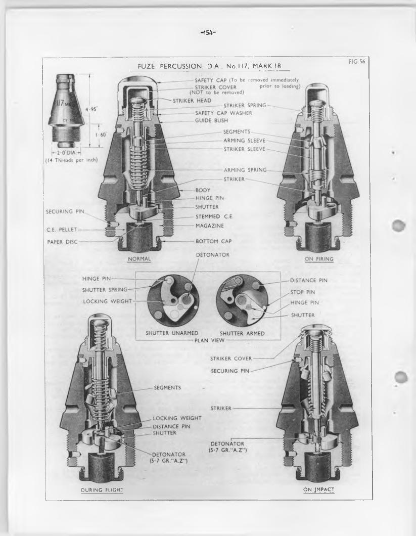
.-154-
FUZE. PERCUSSION. D.A., No. 117. MARK 18 FIG.56
__—-— SAFETY CAP (To be removed immediately________ STRIKER COVER Prior co loading)
(NOT to be removed)
STRIKER HEAD_______________ — STRIKER SPRING------------------- SAFETY CAP WASHER ^
GUIDE BUSH
SEGMENTS
ARMING SLEEVE
STRIKER SLEEVE| - 2 0 D IA H
(14 Threads per inch)
ARMING SPRING
S T R I K E R ~ - ^ _
BODY HINGE PIN
SHUTTERSECURING PIN
STEMMED C.E
MAGAZINEC.E PELLET
BOTTOM CAPPAPER DISC
DETONATORNORMAL ON FIRING
HINGE PIN DISTANCE PIN
SHUTTER SPRING STOP PIN
LOCKING WEIGHT HINGE PIN
SHUTTER
SHUTTER UNARMED SHUTTER ARMEDPLAN VIEW
STRIKER COVER
SECURING PIN
SEGMENTS
STRIKER
LOCKING WEIGHT
DISTANCE PIN SHUTTER
DETONATOR (5-7 G R .-A .Z")
'-DETONATOR (5-7 GR.“A.Z'')
> 1S, - <r
ON JMPACTDURING FLIGHT
- 1 5 5 -
10. Locking weight - This is o f brass and is an arc-shaped fitment located above the magazine and is forked at one end to receive the shutter spring and bored v e r t ic a lly fo r i t s hinge p in . The other end is formed with a toe which is machined to act as a working surface in the recess in. the side o f the shutter under the influence o f the shutter spring, thus masking the central hole in the body diaphragm.
The upper surface o f the toe is recessed to accommodate the point o f the str iker to prevent the shutter opening whilst the fuze is at res t and u n til acceleration has ceased in the gun.
11. Guide bush - This is o f metal and formed with a flange about i t s centre which is coned to suit the contour o f the body and m illed around i t 3 edge. I t is screw-threaded externally above and below the flange, the upper to receive the safety cap and the lower to su it the top o f the fuze body.
I t is bored through the centre to form a guide fo r the s tr ik e r, the upper end o f the boring being enlarged to form a seating fo r the str iker cover and spring. The lower end o f the boring is formed with a countersunk edge to bear against the segments.
A recess on the under surface forms a seating fo r the aiming sleeve. A securing pin locks the threads against unscrewing.
12. Percussion and arming arrangements - These consist o f a s tr ik er with a head, str iker spring, s tr ik er sleeve, segments, arming sleeve and spring.
(a ) S triker - This is o f s tee l and is in two parts e .g . str iker and head, which are secured together by a sp lit pin .The striker is a metal rod circu lar in section having a point at i t s lower end, above which is formed a flange against which bears the lower end o f the str iker sleeve. The upper end is reduced in diameter to f i t the head and bored to receive a s p lit pin.The str iker head is a mushroom-shaped fitment which is bored to f i t the str iker spindle, a rad ia l boring accommodating the s p lit p in . When assembled with i t s sleeve and segments the flange has a small clearance between i t s lower edge and the seating fo r the arming spring in the body diaphragm.
(b ) Striker_spring - This is o f s tee l, c ircu lar in section, and is assembled under in i t ia l compression between the striker head and the upper face o f the guide bush. When the striker is released by the fa l l in g away o f the segments, the spring reasserts i t s e l f , and so doing withdraws the point o f the str iker out o f the recess in the locking weight.
(c ) S triker sleeve - This is o f brass, cy lind rica l in shape and f i t s over the str iker spindle, bearing against the upper face o f the flange on the s tr ik er. I t s upper end is chamfered to bear against the lower countersunk edges o f the segments.
(d ) Segments - These, four in number, form a hollow cylinder around the spindle and are assembled between the lower end o f the guide bush and the upper end o f the s tr ik er sleeve, and maintain the s tr ik e r spring under i t s in i t ia l compression, u n til released by acceleration and centrifugal force.The Tipper edge o f the segments is chamfered, while the lower edge is countersunk, viewing the segments as a cylinder.
(e ) Arming sleeve - This is a hollow cy lin d rica l brass fitm ent, the upper and lower edges being turned over to form bearing surfaces fo r the arming spring and under surface o f the guide bush. The arming sleeve retains the segments in position u n til released by acceleration. The sleeve is kept up to i t s work by an arming spring which is assembled on the outside o f the striker sleeve, one end bearing against the arming sleeve and the other in the recess in the upper face o f the body diaphragm.
13. Str ik e r cover - This is o f brass, dome-shaped and positioned over the str iker head, being seated in the upper recess in the.guide bush. This cover prevents pressure o f the a ir , during f l ig h t , acting on the s tr ik er head, so causing premature action o f the striker.
This cover must not be-removed when preparing the fuze p rio r to loading.
14. Safety cap - This is o f s tee l or malleable cast iron , dome shaped and has a f la t s tee l spring riveted into an oblique s lo t on one side. The free end o f the spring engages in the m illing on the guide bush and retains the cap in position . The cap is formed with a m illed ring around i t s circumference and is screw-threaded in terna lly at i t s lower end fo r attachment to the guide bush.
As an alternative the cap may be manufactured o f z in c-a lloy but is sim ilar in shape to the stee lcap.
The cap is painted or lacquered black externally.
— 156—
15. Safety Arrangements - The following safety arrangements are incorporated
(a ) The safety cap which protects the striker cover and striker.
(b) The segments held in place by the arming sleeve and arming spring which acting through the striker sleeve hold the striker in position in the locking weight,,
(o ) The shutter held by the looking weight in such a position that the detonator is not aligned below the point o f the striker.
16. Action - When preparing this fuze fo r fir in g the black steel safety cap only is to be unscrewed and removed.
17. On fir in g - The acceleration o f the shell in the bore causes the arming sleeve to set back and compress the arming spring between i t s e l f and the bottom o f the recess in the upper surface o f the body diaphragm. This movement uncovers the segments and, combined with a sligh t set baok o f the striker, releases the four segments and permits them to fa l l c lear. Should acceleration not displace the segments they w ill be positive ly displaced by centrifugal force.
18. During f lig h t - As deceleration sets in , the striker spring, which is assembled under compression, reasserts i t s e l f against the underside o f the striker head, forcing the striker and striker sleeve forward until the upper end o f the sleeve meets the under surface o f the guide bush, withdrawing the point o f the striker out o f the recess in the locking wei$it. This allows the locking welgit to revolve around i t s hinge pin under the action o f centrifugal force. In doing so i t s toe starts the shutter turning on i t s hinge pin. This aotion is arranged to ensure that the shutter shall revolve into i t s armed position. The shutter is so shaped that centrifugal force can only cause i t to revolve around i t s hinge pin gently and the locking weight gives i t a start. Centrifugal force then continues to revolve the shutter gently until i t reaches the stop pin which locates -the detonator under the striker point. In this way shook to the detonator, when the shutter moves to the armed position, is avoided. The stop pin is fit ted with a fibre sleeve for the same purpose.
The fuze is now fu lly armed, the striker point being held clear o f the detonator by the striker spring and the retardation o f the shell due to a ir resistance acting on the mass o f the striker.
19. On impact - The striker cover is forced on to the striker head, the striker being forced inwards compressing the striker spring, causing the point o f the striker to pierce the detonator. The resulting detonating wave passes through the magazine diaphragm to the small column o f stemmed C.E. which in turn fires the C.E. p e lle t in the magazine and the bursting charge in the shell.
20. Difference in marks - The following shows b r ie fly the various differences in patterns
Mark 1 (cancelled)This mark was allocated to a design o f No. 117 fuze which was never produced fbr Service
use and has since been cancelled.
Mark 2 (obsolete)This fuze consists o f a body, magazine with bottom cap, shutter with detonator, locking
weight, guide bush, percussion and arming arrangement and safety cap.These fuzes have been modified to approximate to the mark 3 by forming an annular recess
to receive the lower end o f the arming spring. No advance o f numeral being made.
Mark 3 (obsolescent)Similar to the mark 2 but has shape o f shutter amended and may be o f mazak with a brass
insert. Body may be o f zinc base a lloy , has small alterations to dimensions and omission o f upstand round forward end o f striker hole.
Mark 3A (obsolescent)Similar to mark 3 d iffering principally in the shutter recess being fit te d with an
extra distance pin.
Mark 4 (obsolete)D iffers from the mark 3 in being made with a steel magazine, guide bush and body.
Mark 5 (obsolete)D iffers from mark 4 principally in being f it te d with weaker arming and shutter springs.
Mark 6 (Obsolete)Similar to mark 4 but has a cast iron body and mazak ring screwed under the flange, making
a shorter magazine recess. The shorter magazine takes a shorter and narrower p e lle t. Has a longer striker below the flange, also a shorter magazine set screw.
- 1 5 7 -
Mark 7 (cancelled)Sim ilar to the mark 3 "but d if fe r s in being f i t t e d with a modified shutter to aocoanodate
a 6 grain detonator f i l l e d D.C. A. ./lead azide/C.E. (AZY). The s tr ik e r and striker head was o f aluminium a llo y and the thickness o f the magazine diaphragm was .01 - .03 instead o f .003 - .008.
Mark 8 (obsolescent)Sim ilar to the mark 3A. but incorporates a two piece l i^ v t a llo y s tr ik er and s tr ik er head,
to increase the speed o f action o f the fuze by reducing the in e rtia o f the striker.
Mark 9 (cancelled)
Mark 10 (convtd. mark 3A or 8)D iffers from the mark 8 in the fo llow ing respects :-Thicker str iker cover and smaller diameter s tr ik er head and the s tr ik er and str iker head
being o f s tee l.
Mark 11 (convtd. mark 2) (obsolete)D iffers from mark 8 in the follow ing respects: - Thicker s tr ik er cover and smaller diameter striker head.S tee l str iker and s tr ik e r head.Only one distance piece in the magazine recess.Shutter o f brass only and o f a s lig h t ly d iffe ren t design.
Mark 12 (convtd. mark 3) (obsolete)D iffe rs from the mark 8 in the fo llow ing respects Thicker s tr ik er cover and smaller diameter s tr ik e r head.Steel s tr ik er and str iker head.Only one distance pieoe in magazine recess.
Mark 13 (convtd. mark 4 ) (obsolete)D iffe rs from the mark 8 in the fo llow ing respects:- Thicker s tr ik er cover and small diameter s tr ik er head.S teel s tr ik er, s tr ik er head, guide bush, magazine and body.
Mark 14 (convtd. nark 8) (obsolescent)Same as the mark 8 except fo r a thicker str iker cover and smaller diameter str iker head.
Mark 15Sim ilar to the mark 8 except thats- The striker and s tr ik er head are o f s tee l.The s tr ik e r cover is thicker and the s tr ik er head i s o f smaller diameter.
Mark 16 (obsolete)Sim ilar to the mark 10 except that i t i s assembled with a 5.7 gr. A.Z. tinned lugless
detonator, in lieu o f a 5 gr. A.Z. copper shell detonator.
Mark 17Similar to the mark 15 except that i t i s assembled w ith a 5.7 gr. A .Z. tinned lugless
detonator in lieu o f a 5 gr. A.Z. copper sh e ll detonator.
Mark 17/1Sim ilar to the mark 17, but body i s provided with a shutter gauging hole.
Mark 18Similar to the mark 17 d if fe r in g princ ipa lly in the shutter and locking weight being
tin -p lated a l l over and the face o f the w alls o f the shutter recess and central hole guiding the striker and the top face o f the magazine, projecting face o f the distance hinge pin and the stop pins also being tin-p lated. In addition, the body is provided with a shutter gauging hole.
Note:-
Mark 8 and e a r lie r marks - P rio r to 13/10/1942 an instructional label L139 with the legend "DO NOT REMOVE" was a ffix ed to the s tr ik er cover, a fte r th is date th is legend was embossed on the top o f the s tr ik er oover which was manufactured to design P.D. 907.

— 153—
Marks 10. 11. 12, 1 14* 15. 16« 17 and 18 - These marks o f fuzes are assembled with astr iker cover to design D3/5/221VI/3M • The design ca lled fo r a heavier gauge material than that used fo r covers to design P.D. 907, and the increase in thickness o f the sk irt made ‘ removal o f the cover from the fuze impossible without the use o f a special to o l. Embossing the legend nD0 NOT REM3VE" on top o f the cover was, therefore, discontinued.
159—
RJZE PERCUSSION, D.A. AND GRAZE NO. 119 -AND NO. 119B
21. Type P e rc ., d irect action and graze
22. Guns B.L. 9.2 inch gun (C .A .) B.L. 6 inch gun (C .A .)Q.P. 3.7 inch howr. Q.P. 25 pr. gunNot to be used in :-
B.L. k<,5 inch gun B. L, 5.5 inch gun B.L. 7.2 inch howr.
23. P ro je c tile H. E. sh ell
24. Description - No. 119B mark 17 (F ig . 57)
25. General - The fuze consists p rin c ipa lly o f a body, sleeve (in e rt ia p e l le t ) detonator plug, detonator holder, detent, centrifugal b o lt, s tr ik e r assembly, s tr ik e r cover, safety cap, detonators and shutter assembly and magazine with cap.
26. Body - This is o f brass and the lower portion is screw-threaded externally to the 2 inch fuze hole gauge. The upper conical portion ha3 a f la t top, a la te ra l threaded hole in the side fo r a plug to secure the centrifugal b o lt and two key holes to take the key fo r inserting or removing the fuze. A la te ra l threaded hole in the lower threaded portion is fo r a pin to secure the magazine.
The body is bored from both top and bottom to leave a th ick diaphragm with a hole d r il le d through the centre to act as a guide fo r the stem o f the striker. The recess at the top houses the str iker spring which is assembled under the head o f the s tr ik er and also the str iker cover.
The smaller central bore in the lower part o f the body houses the creep spring which i s assembled over the needle shank o f the s tr ik er and rests on top o f the detonator plug.
A s lig h t ly la rger bore below th is acconmodates a spacing washer, followed by the detonator holder0
The lower bore contains the shutter assembly and magazine and is screw-threaded at the bottom to take the magazine.
On one side, o f f centre, a hole is d r il le d in the body to act as a vent to re lieve the pressure in the middle portion o f the body should a detonator f i r e on shock o f discharge, while on the opposite side another hole is d r ille d to house the detent and detent spring.
27. S triker assembly - The str iker is assembled from the lower part o f the body. The str iker spring is then assembled and compressed and retained in th is position by f i t t in g the striker head which is secured to the top o f the s tr ik er by a retain ing pin.
The centrifugal b o lt is then assembled.The creep spring is then assembled over the needle shank o f the str iker from the rear end o f
the body, followed by the sleeve. The creep spring, in e rtia p e lle t u n it, and spacing washer are retained in position by the screwing home o f the detonator holder.
28. Sleeve (in e rt ia p e l le t ) - This is cy lin d rica l and is bored in tern a lly to accommodate at the rear end a 5 grain detonator and above th is on a s lig h t ly la rger diameter i t is screw-threaded to engage the detonator plug. The top portion i s then recessed and the rim chamfered to f i t over the wider end o f the sp ira l creep spring on assembly.
29* Detonator plug - This is cy lind rica l and formed with a threaded flange to screw in to the sleeve. In terna lly a hole is d r il le d through the centre and acts as a housing and guide fo r the needle shank o f the striker.
30. Centrifugal b o lt - This i s cy lin d rica l w ith an undercut formed on the inner face. I t is inserted in the hole in the side o f the body and the head f i t s under a flange formed on the stem o f the s tr ik e r, thus locking the str iker in the safe position*
31. Bolt hole plug - This is o f brass formed with a screw-threaded flange, and a screwdriver s lo t is made in the rear face to fa c i l i ta te insertion . I t is screwed into the body behind the centrifugal b o lt0
32. Detent - This is a metal rod with a rounded knob formed at one end, the knob being lo o s tly enclosed by a cy lind rica l weight.
The stem o f detent is assembled behind the centrifugal bo lt and prevents the bo lt moving outwards u n til a fte r the fuze i s fired .
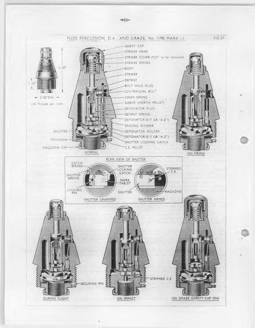
—1 60-
s a f e t y CAP
STRIKER HEAD
STRIKER COVER (NOT to be removed)
STRIKER SPRING
BODY
STRIKER i
DETENT
BOLT HOLE PLUG
CENTRIFUGAL BOLT
CREEP SPRING
SLEEVE (INERTIA PELLET)
DETONATOR PLUG
DETENT SPRING
DETONATOR (5-7 GR. 'A.Z ’)
(14 Threads per inch)
SPACING WASHER
DETONATOR HOLDER
DETONATOR (5-7 GR. 'A.Z'')
SHUTTER LOCKING CATCH C E PELLET
SHUTTER
MAGAZINE
MAGAZINE CAPNORMAL ON FIRING
PLAN VIEW OF SHUTTERCATCHSPRING SHUTTER
LOCKINGCATCH
STEMMED ^ C E
SHUTTERSPRING
PAPERTABLET
LOCKINGPIN MAGAZINESHUTTER
SHUTTER ARMEDSHUTTER UNARMED
STEMMED C ESECURING PIN
ON GRAZE (SAFETY CAP ON)DURING FLIGHT ON IMPACT
Wf aSt
1
FUZE PERCUSSION, D.A., AND GRAZE. No. II9B. MARK 17 FlG.57
_ 1 61-
. 33• Detent spring - This is a sp iral o f spring wire assembled below the detent.Set back o f the detent on acceleration conpresses the spring and the stem o f the detent bee ones
locked under the shoulder formsd in the detent hole in the body,
34. S triker - The aluminium a llo y s tr ik er has a separate mushroom shaped head secured by a sp lit pin.
The s tr ik er spindle is c ircu la r in section, having a sharp point formed at i t s lower end above which a shaped flange formed to make a seating against the diaphragm in the body o f the fuze. Above the flange the stem o f the s tr ik er is thickened, the upper end being reduced in diameter to f i t the head and bored to take a s p lit pin.
The s tr ik er head is bored cen tra lly to f i t the s tr ik e r and rad ia lly fo r the sp lit pin ,
35* Striker spring - This is a sp ira l o f s tee l wire assembled under in i t ia l compression between the str iker head and the upper surface o f the fuze body.
36. Creep spring - This i s a cone o f s tee l w ire assembled under l ig h t conpression between the top o f the detonator plug and under the flange formed above the needle shank o f the striker,
37* Shutter - This comprises a s lid ing block, locking p in , shutter spring, catch spring and a shutter locking catch.
When the shell leaves the muzzle the shutter locking catch spins outwards under cen trifuga l force permitting the shutter (o r block) to s lid e outwards in the armed position where i t is retained by the locking pin.
38. Detonator (upper) - This is a 5*7 gr. AZ tinned lugless detonator,
39. Detonator (low er) - This is sim ilar to the former, and is housed in the detonator holder and secured by ringing,
40. Detonator holderThis is c ircu la r and screw-threaded externally to engage in the body. In tern a lly i t is
recessed to house the 3 grain detonator,
41. Magazine - This is o f brass. The main upper portion is screw-threaded externally to suit the body whilst the bottom part is reduced in diameter fo r the cap. I t is secured in the body by a pin.
The magazine is bored from the base in two diameters, the la rger bore containing a C.E. p e l le t , which is assembled w ith the hard end nearest to the bottom cap. The smaller bore terminates in a diaphragm fran 0.003 to 0,008 o f an inch th ick and is f i l l e d with stemmed C.E, A recess is formed in the opposite end to house the shutter assembly,
42. Magazine cap - This i s screw-threaded in tern a lly to su it the base o f the magazine. I t screws over the bottom o f the magazine and retains the G.E. p e l le t . A fte r f i l l in g , the cap is crimpedin two or more places to prevent i t unscrewing,
43o S triker cover - This brass dome-shaped cover f i t s over the s tr ik er head and is secured by the bottom ridged edge being sprung into an annular groove at the bottom o f the recess formed in the top o f the body.
The cover prevents a ir resistance during f l ig h t from acting on the str iker head to cause premature action o f the striker.
This cover must not be removed when preparing fo r loading,
44o Safety cap - This black-painted s te e l dome-shaped cap has a f la t stee l spring riveted into an oblique slot in the side. The free end o f the spring engages the m illing on the body o f the fuze and retains the cap in position . The cap has a m illed ring arounds it s circumference and is screw-threaded in tern a lly at the lower end fo r attachment to the top o f the fuze body.
The cap may be removed before f i r in g , but NOT the striker cover underneath.
45. Safety arrangements - The fo llow ing safety arrangements are incorporated:-
(a ) Safety cap which protects the s tr ik e r cover and s tr ik er head from accidental damage.
(b ) Centrifugal b o lt which holds the s tr ik er by the edge o f the flange and thus prevents the whole str iker moving backwards.
(c ) The creep spring which keeps the str iker and in e rtia p e lle t apart.
(d ) The safety shutter which prevents the main detonator f ir in g the magazine, i f accidentally detonated, by the in terpo lation o f the so lid part o f the shutter between the two.
f
—162—
46* To prepare the fuze fo r f ir in g - The s tee l cap must not be removed from the fuze u n til the sh e ll to which i t is f i t t e d , is prepared fo r loading. I t may then be removed, or allowed to remain in position , the decision depending upon the nature o f the target about to be engaged.
The brass s tr ik e r cover under the cap is never to be removed.
47 • Action - on f ir in g - Due to acceleration o f the p ro je c t ile , the striker and detent set back conpressing the creep and detent springs respectively , u n til the shaped portion under the surface o f the flange formed around the s tr ik er engages a s im ilarly shaped portion o f the centrifugal b o lt , thus preventing i t s movement and the stem o f the detent sets back and is retained under the shoulder in the detent bore. The shutter remains in the unarmed position , due to fr ic t io n caused by set back, thus ensuring safety in the bore should e ith e r o f the detonators function premeturely,
48. During f l ig h t - Y/hen acceleration ceases the str iker moves forward under the action o f the str iker spring helped by the creep spring, and centrifugal force now causes the locking catch to swing outwards to release the shutter. Further rotation o f the p ro je c t ile causes the shutter and the released cen trifuga l bo lt to move outwards, the former bringing a channel, f i l l e d with steamed C.E, into alignment with the detonators in the fuze. When the shutter arrives in th is position centrifugal force causes the locking pin in the side o f the shutter to come out o f i t s recess and catch behind a lug in the magazine, so retain ing the shutter in the armed position . The sleeve now has a tendency to creep forward due to acceleration , but th is tendency is res isted and checked by the creep spring,
49. On inpact (cap o f f ) - The fuze usually functions by d irect action, the s tr ik e r being driven inwards and i t s point p iercing the detonator in the sleeve. The resulting flash causes the lower detonator to function and a detonating wave passes v ia the stemrjed C.E. in the channels o f the shutter and magazine to the C.E. p e lle t in the la t te r and thence to the bursting charge in the shell.
I f , due to the small angle o f a rr iva l or other causes, the s tr ik er is not driven in , the fuze w i l l function by graze action, as described below.
50. On inpact (cap on) - Against ligh t cover the s tr ik er is rendered inoperative by the presence o f the cap, and the fuze w i l l function by graze action. When th is happens the sleeve with i t s detonator moves forward on to the point o f the striker, immediately the p ro je c t ile is retarded, and the detonator is fired .
Except fo r a s ligh t delay that is inherent in fuzes functioned by graze action, a l l subsequent events are as previously described.
NOTE:- The No. 119 fuze is distinguishable from the No. 117 by having two bands around the body, one knurled and the other coloured black,
51. Difference in marks - The fo llow ing shows b r ie f ly the various differences in patterns:-
No. 119. mark 11This is a mark 3A or 4 No. 119 fuze converted by f i t t in g a new magazine, new type o f
lock shutter, a weaker (20 oz. ) creep spring and a flanged detonator holder. A fte r 12-2-46 the 5 grain A,S.A. main detonator was replaced by a 5 grain AZ detonator.
»•’ unc No. 119BMark 10 (obsolescent)
This is similar* to the No, 119B mark 4 fuze but with new design magazine in zinc a lloy with lock shut shutter, and s tr ik er with s tr ik er head rais ing spring. A fte r 12-2-4^ the 5 grain A.S.A. main detonator was replaced by a 5 grain AZ detonator.
Mark 11This is a mark 1 No. 119B fuze converted in a sim ilar manner to the mark 11 No. 119 fuze.
I t d if fe rs from the mark 10 in not having a s tr ik e r head raising spring, and in having a 3 gr. "A" instead o f a 5 gr. AZ detonator in the in e rtia p e lle t . A fte r 12-2-46 the 5 grain A.S.A. main detonator was replaced by a 5 grain AZ detonator.
Marks 12 and 13These "marks" have been a llo tted to an Indian design.
Mark 14This is a mark 10 No. 119B fuze, converted by being f it te d with a brass magazine,
modified shutter and strengthened head and cover.
*
Mark 15Allotment o f "mark" held in abeyance. No design prepared.
— 163—
‘ ■ark 16This "mark" has been a llo tted to an Indian design
Mark 17 - (as described above)This is iden tica l with the mark 14 except that i t is f i t t e d with a 5.7 grain A.Z. tinned
lugless detonator, in lieu o f a 5 gr. AZ copper shell detonator.
Note: No. 119 mark 11 and No. 119B marks 10 and 11 fuzesP rio r to 13/10/1942 an instructional label L139 with the legend "DC' NOT REMOVE" was
a ffix ed to the str iker cover, a fte r th is date th is legend was embossed on the top o f the str iker cover which was manufactured to design F.D.907.
P r io r to 28/8/1942 an instructional labe l L508 with the legend "THE CAP SHOULD BE LEFT ON WHEN THE TARGET IS BEHIND COVER", was a ffix ed around the sa fety cap. A fte r th is date i t s application was discontinued.
No. 119B marks 14 and 17 fuzesThese marks o f fuzes are assembled with a str iker cover to design D3/I/2214/5/341. The
design ca lled fo r a heavier gauge material than that used fo r covers to design F.D.907, and the use o f a special to o l. Embossing the legend "DO NOT REMOVE" on top o f the cover was, therefore, discontinued.
—1 62 -
RJZE. TIME AND PERCUSSION. D.A. . NO. 213
52. Type Time, mechanical and perc. D.A.
53. Guns 3*7 inch howr. 25 pr. gun4.5 gun5.5 gun 7.2 howr.
54. P ro je c tile H.E. shell
55. Description - Mark 4 (F ig . 58)
56. General - This fuse is f i t t e d with a mechanical timing which is operated by a main spring and controlled by an escapement. The time o f bursting the sh ell can be varied between 0 and 80 seconds a fte r the gun is f ir e d . The upper part o f the fuze is arranged fo r d irect percussion action on impact.
The fuze consists p rin c ipa lly o f a body, dome, head, locking weight, s tr ik er head with needle, detonator holders (upper and low er), p e lle t holder, shutter, magazine and cap, tensioning ring , mechanism, time, 80 seconds, No. 1 and sa fety cap.
The ex terio r o f the body is threaded at the bottom to screw into the nose o f the shell maintained by the done and lower portion o f the head o f the fuze, the tipper portion o f the head being shaped to range the same as the No. 117 and 119 (cap o f f ) fuzes.
The in te r io r o f the body is divided by a platform. The upper part contains the movement, a recess in the underside o f the platform takes the lower 5 gr. A .Z . detonator holder, and the bottom part contains the shutter and magazine.
The done covers the top o f the clock and can be rotated in the fuze body. The dome is retained by a spring tensioning ring which f i t s in an in terna l groove near the foo t o f the done. Inside the head o f the fuze is a locking weight. Set back o f the weight on f ir in g breaks the shear wires and drives in locking pins to jam the dome in the body and to lock the dome as set. Beneath the locking weight is a platform or hand race, across which a shaped s lo t is cu t. Rotation o f the dome positions the s lo t and thereby sets the fuze.
The clockwork mechanism rotates a spring-loaded hand beneath the hand race, and i s driven by a e lain spring and controlled by an escapement through a tra in o f gear wheels.
The clockwork mechanism is started by f ir in g the gun, the hand being released fo r rotation by the set back o f a tr ig g e r .
57. Clockwork mechanism - The clock is as sent) led as a complete unit and fix ed to the top o f the platform in the fuze body.
The mechanism, time, 80 seconds, No. 1 is sim ilar in operation to the mechanism, time, 43 seconds described in the 208 fuze.
58. Head - The head is shaped to suit the contour o f the fuze dome, in to which i t screws. The top is screw-threaded externally to su it the sa fety cap.
In terna lly i t is bored fresn the bottan to acconxnodate the locking weight, a p e lle t holder and on a smaller diameter to accommodate the detonator holder (upper) • While from the top i t is bored to accoranodate the s tr ik e r cup and s tr ik er head with needle. A fter assembly o f the s tr ik e r the recess in the top o f the head is closed by a closing d isc and washer which are secured by turning over a l ip formed in the top o f the head.
59. Body - This is formed with a shoulder below which i t is screw-threaded to the 2 inch fuze-hole gauge. Above the shoulder is an inclined surface graduated *0" to "80" with a safety mark engraved and f i l l e d in w ith red in the space between the figures 80 and 0.
In terna lly the body contains the clockwork mechanism in the upper part and below th is is a detonator. A s lo t in the top o f the magazine houses a movable shutter retained in the unarmed or safe position by a s tee l spring.
60. Striker - This consists o f a s tr ik er head and needle. The needle being formed with a flange which seats in a rece3B formed in the striker head in which i t i s secured by turning over a l ip .
The str iker is held o f f the upper percussion detonator by a str iker cup through the centre o f which the needle protrudes.
61. Detonator holder (upper) - This cy lin d rica l brass holder has a flange formed at the base. In terna lly the top is recessed to take the 5»7 g r . A.Z. detonator and below th is i t is bored to form a f i r e channel.
I t is inserted in the fuze head from underneath, with the detonator imoediately beneath the str iker needle.
-165 -
62. Detonator holder (low er) - This is assembled o f f centre on the underside o f the platform and above the s lid ing shutter. The holder is recessed to accommodate a 5*7 gr. A.Z. detonator which is secured in position by burring over a l ip formed on the holder. A hole is bored through the bottom o f the detonator recess to permit the flash from the detonator passing on to the oblique channel in the shutter when in the armed position .
63* P e lle t holder - This is o f aluminium a llo y cy lind rica l in shape. Externally i t is screw- threaded at the top, and a hole is formed in the base. I t contains a perforated gun-powder p e lle t .
I t is assembled in the head below the flange on the detonator holder (upper).
64o Shutter - The brass shutter slides in a s lo t on top o f the magazine.At one end is an oblique channel f i l l e d with C.E. stemmed in . A small hole in the side takes
the end o f a stee l shutter spring which pivots on a dowel pin and keeps the shutter at the centre in the unarmed or safe position . In th is position the oblique channel is c lear o f both the detonator and magazine channel.
When the shell is in f l ig h t , cen trifuga l force overcomes the spring and pu lls the shutter outwards to the open or armed position .
In th is position the lower detonator, shutter channel, and magazine channel are a l l in lin e .
65. Detonators - These are both 5»7 gr. AZ tinned lugless detonators.
66. Magazine securing ring - This is a brass c o lla r screw-threaded on the outside to enter the fuze body from underneath. I t surrounds the magazine and secures i t by bearing on the under surface o f the flange formed on the ripper part o f the magazine. The ring is secured by a set screw inserted from the side o f the threaded portion near the bottom o f the fuze body.
Pour s lo ts at the bottom are fo r an assembly to o l.
67. Magazine - This is o f brass and is screw-threaded externally at the bottom to take a bottom cap. I t is bored from the underside to form a recess to take a C.E. p e l le t , the p e lle t being retained in position by the bottom cap.
A flange is formed towards the top o f the magazine, the under surface o f which forms a bearing fo r the magazine securing ring. The top forms a platform fo r the shutter assembly.
A s lo t across the top accommodates the s lid ing shutter. A dowel pin in the recess forms a p ivot fo r the shutter spring and another positions the magazine to the fuze body platform.
A small channel o f f centre, with a diaphragm o f metal l e f t at the top, leads from the shutter s lo t to the recess in the magazine. I t is f i l l e d with C.E. stemmed in .
The magazine is held in position by the magazine securing ring.
68. Bottom cap - This may be o f brass, aluminium a llo y or s te e l, and is threaded in terna lly . I t screws over the bottom o f the magazine and retains the C.E. p e l le t . A fter f i l l i n g the magazine, the cap is screwed on and then crimped in two or more places to prevent i t unscrewing.
69. Safety cap - This is o f s tee l or malleable cast iron , dome shaped and has a f la t s tee l spring riveted into an oblique s lo t on one side. The fre e end o f the spring engages in the m illin g on the head o f the fuze and retains the cap in position . The cap is formed with m illed ring around its circumference and is screw-threaded in terna lly at i t s lower end fo r engagement with the threads formed on top o f the fuze head.
The cap is painted or lacquered black externally .
70. Safety Arrangements - The fo llow ing safety arrangements are incorporated:-
(a ) When the fuze is set at SAFE, the hand race in the dome is coincident with the hand which is prevented from r is in g by the muzzle sa fety device bridge.
(b ) The tensioning ring prevents the dome being accidentally moved during trans it.
(c ) The centrifugal safety catch is housed under the str iker cam u n til the shell rotates in f l ig h t . I t serves a dual purpose
( i ) In the event o f the clockwork mechanism being accidenta lly set in action, the catch prevents the s tr ik er reaching the detonator.
( i i ) I f a fuze with the clockwork mechanism accidentally set in action was loaded and the gun fire d , the centrifugal sa fety catch would be prevented fran swinging out from under the cam as the la tte r would, immediately the hand is l i f t e d , jam down on to a step cut in the catch fo r th is purpose.
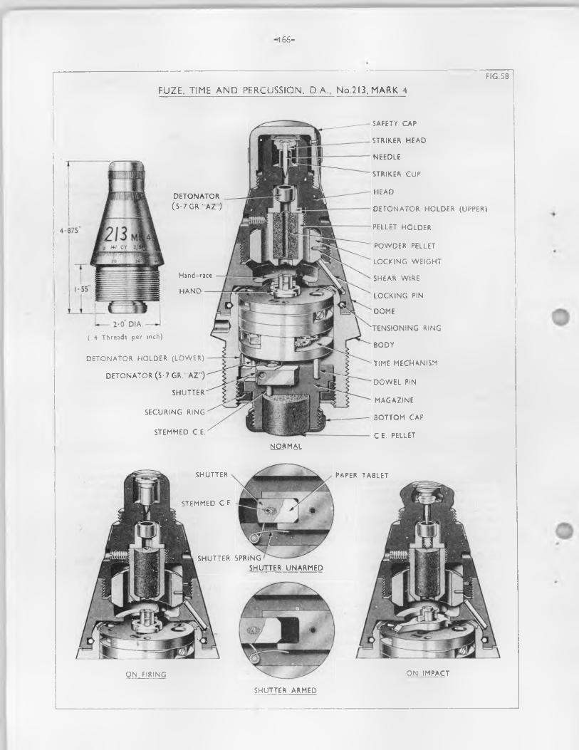
■1 6 6 -
FUZE. TIME AND PERCUSSION. D.A., No.2l3, MARK 4FIG .58
SAFETY C A P
ST R IK ER H E A D
N E E D L E
ST R IK ER C U P
H E A D
D E T O N A T O R H O L D E R (U PPER)
PELLET H O L D E R
P O W D E R PELLET
L O C K IN G W E IG H T
SH E A R W IR E
L O C K IN G PIN
D O M E
R IN G
B O D Y
T IM E M E C H A N IS M
D O W E L PIN
M A G A Z IN E
B O T T O M C A P
C E. PELLET
D E T O N A T O R
(5 -7 G R . ' A Z ")
Hand-race
H A N D
( 14 Threads per inch)
D E T O N A T O R . H O L D E R (LOW [ER)
D E T O N A T O R ( 5 - 7 G R . "
SH U T T ER
S E C U R IN G R IN G
ST E M M E D C.E.
N O R M A L
SH U T T ER SP R IN G
S H U T T ER U N A R M E D
O N IM P A C T
ST E M M E D C.E
O N F IR IN G
S H U T T ER A R M E D
SH U TT ER PAPER T A B LET
— 1 67—
• 71* Action o f timing mechanism - P r io r to loading, the fuze is set to the time required, and the safety cap removed.
72. On f ir in g - The locking weight in the head sets back, shearing the copper pins and forcing the locking pins into recesses in the body thus locking the dome to the body and preventing any movement o f the dome from the set position .
The tr ig g e r sets back and the tr ig g e r locking b o lt is forced outward by i t s spring to reta in the tr ig g e r . The hand is now released from the tr ig g e r , but prevented from r is in g by the muzzle safety device bridge.
During acceleration in the bore i t is unlikely that the p a lle t w i l l o s c illa te owing to the force o f the set back. When the muzzle is reached the hand begins to rotate in an anti-clockwise d irection by the action o f the main spring.
On acceleration ceasing the centrifugal sa fety catch f l i e s outwards, due to centrifugal fo rce, and leaves the striker supported by i t s cam resting on the p i l la r .
73• During f l ig h t - The shutter moves outwards against i t s springs, by centrifugal fo rce , bringing the f i r e channel coincident with the lower detonator and the channel leading to the magazine.
When the clockwork mechanism has run the prescribed time according to the settin g , the hand has been brought immediately under the s lo ts in the hand race and r ise s under the influence o f i t s spring to release the lever which controls the striker. The release o f the le v e r allows the spring to rotate the cam o f f the p i l la r and force the s tr ik er down on the detonator.
The striker is forced by i t s spring into the detonator, which fir e 3 . The flash passing through the stemmed C.E. channel in the shutter to the C.E. p e lle t in the magazine.
74. Action o f Percussion Arrangement - On f ir in g - The acceleration o f the shell in the bore causes the shutter to set back and set up su ffic ien t fr ic t io n in i t s recess to reta in the shutter in the unarmed position whilst the shell is in the bore.
73. During f l ig h t - When acceleration ceases, the shutter moves forward by momentum and outward by centrifugal fo rce , to bring i t s f i r e channel coincident with the lower detonator and the channel to the magazine.
76. On impact - The cap having been removed before loading, the s tr ik er head is crushed in and the needle pierces and f ir e s the upper detonator. The resultant wave explodes the gunpowder p e lle t , the flash fromvfhich passes through the dome and fuze body to detonate the lower (tim e) detonator. The action is then described under action o f timing mechanism.
77. D ifferences in marks - The fo llow ing shows b r ie f ly the various d ifferences in patterns:-
Mark 1 (obsolescent)
Mark 2The mark 2 fuze is sim ilar to the mark 1 d if fe r in g ch ie fly in the former incorporating an
internal locking device, the tensioning screws requiring less pressure; the p e lle t holder being secured by a set screw and magazine assembly secured by a copper securing pin.
Mark 3D iffe rs from the mark 2 in being f i t t e d with two 5.7 gr. A.Z. tinned lugless detonators in
l ie u o f two 5 grain AZ copper shell detonators.
Mark 4(described above)Identical to the mark 3 except that the body (magazine ca v ity ), pins, detonator holder (upper
and low er), magazine (top fa c e ), securing ring , str iker cup and detonator washer are tin -p la ted .
— 168—
FUZE. TIME AND PERCUSSION GRAZE NO. 221 AND NO. 221B
78. Type Time and percn., graze
79* Guns Q.F. 25 p r. gunQ.P. 3«7 inch howr.B.L. 5*5 inch gun
80. P ro je c t ile B .E ., smoke, f la re and chemical sh ell
81. Description - No. 221B Mk. 4 (P ig . 59)
82. General - The fuze is a double banked tension fuze o f metal f i t t e d with a brass cover. The standard time o f burning under normal atmospheric conditions is 49a seconds.
I t consists o f a body, bottom and top rings, cap, base plug, time needle p e lle t with needle and spring, percussion needle p e lle t with needle and creep spring, detent, detent spring and centrifugal b o lt.
83. Body - This is formed with a flange or platform , below which i t is screw-threaded to the 2 inch fuze-hole gauge. Above the platform is formed a short stem having the top reduced in diameter and screw-threaded externally to receive the cap. The flange o f the body is graduated around i t s outer edge fran 0 to 22. On the ungraduated portion between the figures 28 and 0 a safety mark is engraved with the word "SAFE" engraved beneath i t .
The stem is bored cen tra lly from the top to receive the percussion arrangements and screw- threaded to receive the detonator holder and plug. An additional boring to one side o f the central channel contains the time arrangement and time detonator, and is connected to the port on the outside o f the stem by two oblique flash holes. The lower part o f the body i s bored and recessed to form a magazine, and has an oblique and ve r t ic a l channel connecting the magazine with the top o f the platform and the bottom time ring . The channels contain perforated powder p e lle ts .
A recess in the stem bored through the base receives the detent and detent spring and is closed by a screwed plug. A horizontal recess bored through from the side o f the stem and connecting with the detent recess, contains the centrifugal b o lt , the la t t e r locking the percussion arrangement in the safe position . The cen trifuga l bo lt is prevented from removing outwards by the detent and spring.
Key holes are formed in the side o f the platform fo r fix in g purposes.
84. Bottom Ring - This is bevelled on the outer edge and has a concentric groove f i l l e d in with RD 202 pressed fuze powder nearly a l l round i t s under surface, a small recess being bored in the top surface coincident with the commencement o f the groove and containing a perforated powder p e lle t .An oblique channel connects the powder p e lle t and the fuze powder.
A gas escape, having a perforated powder p e lle t , is provided in the outer edge. The ring is assembled over the stem o f the body, round which i t is fre e to revolve fo r setting purposes. The ring is lacquered red.
85. Top ring - This is sim ilar to the bottom, but is o f a smaller diameter. The oblique channel leading from the concentric groove passes to the inner surface o f the r in g , and, when the ring is assembled over the stem, the end o f the channel is positioned to reg is te r with the port in the side o f the stem. The ring is prevented from turning by a brass pin f i t t in g in to corresponding semicircu lar recesses cut in the ring and stem. The concentric groove is f i l l e d with 30 second fuze powder.
86. Cap - This is o f aluminium, cone shaped, bored and screw-threaded to f i t over the stem o f the body. Two key recesses are foimed in the sides fo r tightening the cap u n til su ffic ien t tension is applied to the bottom ring. I t is secured in position by two set-screws.
87. Base Plug - This has a central perforation which i s closed by a brass washer and paper disc shellacked together.
88. Magazine - The magazine is f i l l e d with 60 grains o f G.2C gunpowder and is then closed by the base plug.
89. Washer fo r sealing jo in t between sh ell and fuze - A s tee l "washer, se lf-cen trin g , 2.3 inch" or "washer, copper and asbestos, 2.3 inch" is f i t t e d under the flange o f the fuze to make a waterproof seating between the fuze and l ip o f the sh e ll.
NOTE: This applies only to No. 221B marks 1 ,2 and 3 fuzes. I t is not used with fuzesmanufactured with a stepped shoulder

-169-
c o v e r
FUZE, TIME AND PERCUSSION GRAZE. No. 221B. MARK 4TIME
M EC H AN ISMA R R A N G EM E N T O F TIME
A N D PERC U SS IO N M ECH AN ISM SPERCUSSIO N
M EC H AN ISM
(2-5 GR.. PERCUSSIO N "B P " ) D ET O N A T O R
D E T E N T — -
CENTRIFU G ALBOLT
TIME D ET O N A T O R (2-5 GR i / H O L D E R - B l
INERT IAPELLET
D ET O N A T O RPLUG
D ET O N A T O RH O LD ER
DETENTSPRING
r PERCU SS IO N D ET O N A T O R
| CREEP SPR ING
C EN TR IFU G AL ,BOLT
D E T E N T [
INERT IA PE LLET -J|||g$
DETENT SPRING-/ '
TIMED ET O N A T O R
H O LDERTOP R ING
BOTTO M R ING
B O D Y
FUZE PO W D ER
.TIME SPR ING
PO W D ERPELLETS TIME NEEDLE
B O D Y
M A G A Z IN E BASE PLUG
A C T IO N OF T IME M EC H AN ISM A C T IO N O F PERCU SS IO N M EC H AN ISM
O N FIR ING O N IMPACT
O N G R AZE
BO TTO M RING FUZE PO W D ER
M EALED PO W D ER TO P R ING FUZE P O W D ER
INERTIAPELLET
DETENT
DETENTSPRING
D U R IN G FLIGHT
CEN TR IFU G AL BOLT M A G A Z IN E

- 1 7 0 -
90. Detonators - Both the time and percussion are 2.5 gr. B.P. detonators.
91. Time arrangement - The time detonator holder is supported on the co iled sp ira l spring and has the underside recessed to receive a detonator. The spring supports the detonator holder, keeping the detonator c lea r o f the needle u n til set back takes place on f ir in g .
92. Percussion arrangement - This consists o f a needle, in e rtia p e lle t , creep spring and detonator contained in the central channel o f the stem. The needle is prevented from moving forward by the inner end o f the centrifugal b o lt engaging in a recess in the side o f the in e rtia p e lle t .
93. In ertia p e lle t - This is cy lin d rica l, with a flange formed near the top above which the diameter is reduced and screws threaded in terna lly to engage the needle. Two slo ts are formed in the sides from the flange to the bottom o f the p e lle t to act as flash channels from the percussion detonator to the magazine.
94. Creep spring - This is a sp ira l s tee l wire spring. The la rger end is assembled under the detonator holder, whilst the smaller end f i t s over the needle point and rests on top o f the in e rtia p e lle t . When the centrifugal bo lt is disengaged i t prevents the in e rtia p e lle t creeping forward on to the detonator.
95. Cover - This is a No. 5 Cover to T. and P. Fuzes and is o f brass, f i t t e d with a round rubber ring at i t s lower end and is provided as a waterproof covering. I t is coned shaped and assembled over the fuze, being secured by a band which is pressed t ig h t ly round the fuze, and secured by so ft copper w ire , the ends o f which are twisted and tucked under the band. A lte rn a tive ly , the cover may be held in position by a securing band secured by a tongue engaging in a s lo t , the tongue being turned over.
96. Safety arrangements - The fo llow ing sa fety arrangements are incorporated:-
(a ) The in e rt ia p e lle t is held by a cen trifuga l b o lt .
(b ) The resistance o f the sp ira l spring keeps the time p e lle t c lear o f the s tr ik e r.
(c ) When set "sa fe" the top ring is masked from the magazine time detonator.
97* Action o f time arrangement - Before loading, the cover must be removed, and the fuze set to the time required.
98. On f ir in g - The time detonator holder sets back, overcomes the resistance o f the co iled sp ira l spring, and carries the detonator on to the needle. The flame from the detonator passes through the flash holes in the stem to the top time r in g , where i t ign ites the fuze powder p e lle t in the gas escape hole, blowing out the brass d isc,
99. During f l ig h t - The powder in the top ring burns round u n til i t reaches the recess in the top surface o f the bottom rin g , explodes the powler p e lle t and ign ites the powder in the bottom ring , at the same time clearing the gas escape hole. The powder bums round in the opposite d irection to that o f the top ring u n til the channel leading to the magazine is reached. The flash passesto the magazine and thence to the bursting charge o f the sh e ll.
100. Action o f percussion arrangement - On f ir in g - The acceleration o f the shell causes the detent to set back, compressing the detent spring, and releasing the centrifugal b o lt . The rotation o f the shell causes the b o lt to move outwards from i t s recess in the body leaving the in e rt ia p e lle t free to move forward on inpact or graze.
101. During f l ig h t - The tendency o f the p e lle t to move forward, in consequence o f deceleration, w i ll be checked by the creep spring.
102. On impact or graze - The p e lle t overcomes the creep spring and carries the needle on to the detonator. The resultant flash passes through to the magazine which is exploded, should the time arrangement not have functioned during f l ig h t .
103. D ifferences in marks - The fo llow ing shows b r ie f ly the various d ifferences in patterns
Fuze No. 221Mark 1 (obsolete )
Mark 1* (obsolete)D iffe rs from mark 1 by th e ir needles being secured to prevent them becoming loose in the
in e rtia p e lle ts . These fuses were modified in 1942.
- 1 7 1 -
Mark 2 (obsolete)D iffe rs from the mark 1 in being f i t t e d with a p la stic cap, in having a stepped shoulder and
therefore requires no washer,
Mark 2* (obsolete)D iffe rs from mark 2 by th e ir needles being secured to prevent them becoming loose in the
in ertia p e lle ts . These fuzes were modified in 1942.
Fuze No. 221BMark 1 (obsolescent)Sim ilar to the mark 1 No. 221 but is f i t t e d with a weaker detent spring.
Mark 2 (obsolescent)Similar to the mark 2 No. 221 but is f i t t e d with a weaker detent spring.
Mark 3This is o f new manufacture. I t d if fe r s from the mark 1 No. 221B fuze in having:-
(a ) Weaker detent spring (2 lb . oz. instead o f 3 lb . 6 o z . ) .
(b ) New magazine base plug without upstands.
(c ) Shorter in e rtia p e lle t having a guide band at each end.
(d ) A new percussion detonator holder and plug to bring the detonator lower in the fuze body.
(e ) A conical instead o f a cy lind rica l creep spring.
( f ) The top cap (o f aluminium a lloy only) re-designed so that the grub-screw bears d ire c t ly on the body.
The grub-screw is inserted, a fter tensioning, in the hole nearer to the 22 graduation to ensure that the point o f the screw does not enter the gash fo r the time detonator holder.A fter 15/9/43 the grub screw holes in the cap were counterbored so that the second hole could be closed by a screwed plug.
Mark 4 (described above)Sim ilar to the mark 3 but has a stepped shoulder.A fter 22/6/1+2 the two piece time needle was deleted.The upstands on the magazine base-plug were omitted a fte r 30/6/42 and the diameter o f the
f i l l i n g hole increased sifter 15/2/43 to fa c i l i t a t e f i l l in g . A fte r 23/11/44 a new base plug without a f i l l i n g hole was f it te d .
A fter 30/1/43 the tension required to turn the bottom ring was increased from 250 _+ 20 to 450 + 50 incl/ozs.
A fter 11/6/43 the a lternative cap o f p la s tic was deleted.A fte r 20/9/43 the depth o f the bore fo r the centrifugal bolt and the length o f the bo lt were
amended to increase the clearance from the in e rtia p e lle t in the armed position by .040 inch.
NOTE:- From 9/6/49 approval was given fo r the omission o f the d is tin ctive red lacquering (denoting slow binning composition) from the lower rings.
Fuze No, 221T (obsolete)Mark 1These are modified No. 221 fuzes.The modification consists o f the removal o f the percussion detonator and plug.The le t t e r MT" is s ten cilled in blue on the top cap and cover.
-1 7 2 -
FUZE. PERCUSSION. BASE. MEDIUM L15
104. Type
105. Guns
106. Pro.leotile
Pero ., base, medium with delayed arming shutter
Q.F. 25 pr. gun; 120 ms. L1 and L2 guns
H.E. shell
107. Description - Model A1 (P ig . 60).
108. General - The fuze consists p rin c ipa lly o f a body, magazine and oap, str iker assenbly, oreep spring, str iker locking segment and delayed aiming shutter No. 3 containing a 2.8 grain "AZ" detonator.
109. Body - This i s o f aluminium a llo y - anodised a l l over. I t is cy lin d rica l in shape with a wide flange formed at the base above whioh i t is screw-threaded externally to 1.80 L.H. gauge fo r approximately a quarter o f i t s length, the remainder o f the body being l e f t p la in . A hole i s d r i l le d in the centre o f the base .and screw-threaded to accept a tracer-adapter (120 ran. sh e ll on ly ). Two key holes diagonally opposite are also formed in the base to enable the fuze to be inserted or removed from the sh e ll.
In terna lly , the body is bored from the top in four diameters, the smaller a t the base to acconmodate the s tr ik e r and creep spring, the second and th ird, which are s lig h t ly la rger in diameter, accoranodates the str iker locking segment, whilst the fourth and la rgest is screw-threaded at the mouth. This la rger recess accommodates the delayed arming shutter above which the magazine is screwed home.
The base and flange o f the body i s coated with varnish a fte r the marking has been stamped on.
110. S triker - This consists o f a brass electro-tinned cy lin d rica l body, with a flange a t the base above which i t i s formed on three decreasing diameters, a recess being formed in the top o f the smallest diameter fo r the electro-p lated t in or zinc ooated s tee l needle, the stem o f which protrudes through the centre o f the str iker locking segment. The needle, the base o f which i s flanged, is retained in the recess in the top o f the body by a t in coated brass washer which i s secured by spinning over a l ip a t the top o f the reoess. The needle i s fre e to move sideways in i t s recess.
The s tr ik er i s inserted in to the cavity in the base o f the fuze body together with the creep spring which i s assembled around the la rger diameter o f the str iker body, the bottom c o i l resting on the flange. The creep spring i s retained under in i t i a l compression by the top c o i l seating in a recess and bearing against the base o f the s tr ik er looking segment.
111. Creep spring - This i s cy lin d rica l co iled tinned s tee l w ire spring, w ith four e f fe c t iv e c o ils o f .056 d ia , w ire, one o o il a t each end being close co iled and ground square with the axis o f the spring. I t i s assembled round the la rger diameter o f the s tr ik er body and prevents the assembled str iker creeping forward when the sh e ll i s in f l ig h t .
112. S triker locking segment - This is assembled in the fuze body, the lower portion f i t t in g over the top o f the s tr ik e r. I t is retained in position by a screw inserted through the side o f the fuze body, the shank o f which bears on the s tr ik e r locking segment cover.
The str iker looking segment comprises a holder, two e lectro t in plated s tee l pins, two springs, two segments, a washer and a cover.
113. Holder - This is o f aluminium a llo y , cy lin d rica l in shape. Externally i t is formed in tiro diameters, the la rger being a t the top. The bottom portion o f the la rger diameter i s chamfered to blend with the smaller. The bottom o f the smaller diameter is also chamfered.
In terna lly , from the base i t is bored out in two diameters, whilst a recess i s formed in the top face to house the two locking segments, leaving a platform o f metal between the top and bottom.A hole, the lower edge o f which i s chamfered, i s d r il le d through the centre o f the platform to permit the str iker to pass through. In the base o f the recess in the top o f the holder, near the periphery, two holes diam etrica lly opposite are d r il le d to accept the stee l pins over whioh are assembled the co iled springs and the segments. When assembled, the tops o f the two pins protrude above the top surface o f the holder.
114. Segments - These are o f aluminium a llo y , and are p e r fec tly f la t irregu lar arc-shaped fitments. One end is in the form o f a toe which i s machined to aot as a w rk ing surface when the two segments are assembled in the unarmed or locked position , the other end i s wider and acts as a weight which, under the influence o f cen trifuga l force, overcomes the springs and allows the two segments to open out. Two holes are d r il le d near the toe, the la rger to f i t over the pin on which the segment p ivots, the smaller acooranodating the turned up end o f the segment spring. In the closed or unarmed position the top portion o f the striker bears against the underside o f the closed segments, and thus the s tr ik er is prevented from moving forward u n til the segments are opened by centrifugal fo rce.
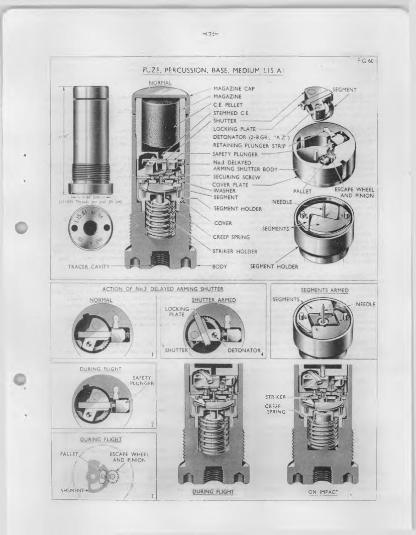
■ 173'
*
NORMALMAGAZINE CAP MAGAZINE C E PELLET STEMMED CE.SHUTTER -----------------------LOCKING PLATE
DETONATOR (2-8 GR , "A Z")
RETAINING PLUNGER STRIP ^
SAFETY PLUNGER -------
No 3 DELAYEDARMING SHUTTER BODY ---------SECURING SCREWCOVER P L A T E ---------------WASHERSEGMENT
NEEDLESEGMENT HOLDER
SEGMENT
ESCAPE WHEEL __AND PINION
PALLET
COVERSEGMENTS
CREEP SPRING
STRIKER HOLDER
SEGMENT HOLDERTRACER CAVITY BODY
ACTION OF No 3 DELAYED ARMING SHUTTER SEGMENTS ARMED
SEGMENTSSHUTTER ARMEDNORMALNEEDLE
LOCKING PLATE ,
SHUTTER DETONATOR
FIG.60
FUZE, PERCUSSION, BASE. MEDIUM. LI5. Al
DURING FLIGHT
SAFETYPLUNGER
DURING FLIGHT
PALLET.,
/
ESCAPE WHEEL AND PINION
SEGMENT/ 3 ON IMPACTDURING FLIGHT
STRIKER
CREEPSPRING
-174-
115- Segment spring - These are o f 0.022 tinned stee l w ire, with 6.2 close wound, c o i ls , the ends o f the wire being bent up at lig h t angles to the c o ils . These are assembled over the pivot pins and underneath the segments, the lower end o f the spring f i t t in g in to a small hole d r ille d in the holder adjacent to the pin, whilst the upper end o f the spring is located in a small hole d r il le d in the segment•
116. Washer - This is o f aluminium a llo y , in the form o f a f la t disc with a hole formed in the centre, and two s lo ts diam etrically opposite near the periphery.
I t is assembled on top o f the holder, the protruding ends o f the p ivo t pins being located in the s lo ts , and the point o f the needle protruding through the central hole.
117* Cover - This is o f aluminium a llo y , formed with a la rge hole in the centre. I t f i t s over the top o f the holder and retains the washer in position above the segments. I t i s secured in position by spinning the bottom edge over around the external chamfered portion o f the holder.
118. Delayed arming shutter - This consists o f a rotary type shutter containing a 2.8 grain "AZ" detonator assembled in a c ircu la r shaped shutter body. The shutter is held in the "unarmed” position by means o f a spring-loaded safety plunger which engages in a locking p la te . The sa fe ty plunger is retained in a recess in the side o f the shutter body o f a plunger retaining s tr ip . On spin, the safety plunger disengages by centrifugal force and the shutter rotates u n til the detonator is in a central position over the s tr ik e r hole. The locking p la te , which f i t s in to a s lo t made across the face o f the shutter, moves out and engages in a recess made in the outer side o f the shutter body, thus locking the shutter in the "armed" position . The delay is obtained by means o f a p e lle t and pinion mechanism positioned beneath the shutter and th is osc illa tes a segment by means o f a ' scape wheel and pinion which retards the opening o f the shutter. The approximate time o f arming is 0.02 to 0.055 seconds from the time the shutter coircnences to open.
The D.A. shutter assembly is assembled in the fuze body below the magazine. I t is located and prevented from revolving by a screw inserted through the side o f the fuze body which enters a s lo t formed in the side o f the shutter body. I t is further secured by a screw inserted through the side o f the fuze body, the stem o f which enters a hole d r il le d in the side o f the shutter body. The threads o f both screws are coated with cement, and the thread is stabbed a fte r screwing home. The slotted end o f the screws is then coated with cement.
119* Magazine - This is o f aluminium a llo y - anodised a l l over. I t is cup-shaped and screw-threaded externally comnencing at the mouth fo r about two-thirds o f i t s length, the remaining portion being s lig h t ly reduced in diameter and l e f t p la in . Two key s lo ts are formed in the outer rim to fa c i l i t a t e assembly. In terna lly , the magazine is bored, out to take a prepressed p e lle t o f C.E. and a small recess which is f i l l e d with loose C.E. stenmed in , i s d r il le d in the centre at the bottom, leaving a thin diaphragm o f metal between the recess and the outer surface a t the base o f the magazine.
The magazine is screwed in to the open end o f the fuze body, the base o f the magazine resting above the delayed arming shutter. The outer end o f the magazine protrudes above the body o f the fuze, and is closed by the magazine cap.
120. Magazine cap - This is o f aluminium a llo y — anodised a l l over* I t is cup-shaped with an internal thread to screw over the mouth o f the magazine, the threads being coated with RD 1285 or RD 1285 A p r io r to assembly.
121. Safety arrangements - The follow ing sa fety arrangements are incorporated: -
(a ) Creep spring between flange on s tr ik e r and base o f s tr ik er locking segment.
(b ) S tr iker locking segment
(c ) Rotating delayed arming shutter retained in the safe or unarmed positioned by a spring-loaded centrifugal sa fety plunger.
122. On leaving the muzzle - Centrifugal force sets in motion the mechanism o f the delayed arming shutter and also causes the segments in the str iker locking assembly to move outwards, leaving a clear passage fo r the s tr ik er to move forward.
A fte r a pre-d.etermined time the D.A. shutter moves in to the correct position fo r the detonator to be d ire c t ly above the point o f the s tr ik e r . In th is position the fuze is "armed".
123* On impact - The momentum o f the s tr ik er causes i t to set forward compressing the s tr ik er creep spring, and permits the point o f the needle to p ierce the detonator. The resultant flash is communicated to the C.E. p e lle t in the magazine v ia the stemmed C.E. in the recess above the diaphragm, and then passes on to detonate the H.E. charge in the sh e ll.

- 1 7 5 -
124. D ifferences in marks - The following shows b r ie f ly the various d ifferences in patterns:-
Model A1(described above)
A lim ited number only o f these fuzes stamped L15A1 were produced and these were manufactured p r io r to the drawings being sealed.
Model A2This is sim ilar to the model A1 d iffe r in g ch ie fly in the under-flange o f the s tr ik er
being chamfered and minor modifications introduced to obviate damage to the s tr ik er points during assembly. These modifications were incorporated in the drawing at the time o f sealing.
—176—
FUZE. PERCUSSION. D. A. NO. 162
125. Type
126o Mortars Mark 1 Mark 1/2 Marie 1/3 Mark 4
Direct action, percussion
3 inch mortar
Mark 3 Mark 3/1 Mark 3/2 Mark 3/3 Mark 5
4.2 inch mortar
127. Nature o f b mbs H.E. and smoke W.P., C.S.A.M. and F.M.
128. Description - Marie 3/3 (F ig . 61)
129. General - The fuze consists p rin c ipa lly o f a body, s tr ik e r w ith spring, retain ing h a ll and safety pin ; shutter w ith spring, hinge pin , detonator, detent with spring, s tee l d isc, septum, magazine, cap and safety cap.
130. Body - This is o f zinc a llo y and at i t s upper part has a cannelure formed to acconmodate the cap and below th is i t i s screw-threaded externally for engagement o f the sa fe ty cap. A touujy hole is formed through the threads fo r fix in g purposes. About the centre a flange is formed below which the body i s screw-threaded (R.H .) to 1.375 inch diameter to suit the fuze hole o f the bonfc, a fte r which the remainder o f the body is formed p la in . In tern a lly , i t is formed w ith & numbero f recesses to house the in tegra l parts o f the fuze. Detent and shutter inspection holes are d r il le d through the side o f the body and closed by grub screws.
131. S triker - This i s o f a l l s te e l, the lower end being formed pointed to p ierce the detonator, and the upper e » I having a c ircu lar f l a t head s l i^ i t ly below which is formed a coned flanged portion to acconmodate the retain ing b a ll when the fuze is unarmed. I t is zinc p lated a l l over.
132. S triker spring - This is o f co iled s tee l w ire the last c o i l at each end being la id f la t .I t is assembled beneath the flange on the s tr ik e r and raises the s tr ik er in the armed position when the detent sets back and the b a ll drops in to the oblique recess in the fuze body.
133* Detent - This consists o f a short anodised aluminium a llo y rod, the top end o f which is chamfered. I t rests on top o f the detent spring and is retained in the body by canneluring on o f the cap.
134. Detent spring - This i s a cy lin d rica l co iled s tee l w ire spring and is assembled under in i t ia l conpression below the detent.
135. Shutter - This is pear-shaped and p ivots on a brass hinge pin , the large end being recessed to accommodate the detonator which is retained in position by a washer and secured by turning over a burr formed on the shutter.
136. Shutter spring - This is a co iled s te e l wire spring having two arms, one o f which engages in the recess in the side o f the shutter the other bearing against the side o f the fuze body. When the point o f the s tr ik e r is raised by the action o f the s tr ik e r spring, the shutter rotates to the armed position so that the detonator is positioned d ire c t ly under the point o f the striker.
137* Detonator - This consists o f a copper a llo y sh ell tinned a l l over containing 2.8 grains o f "AZM detonating composition pressed in , above which is assembled a paper disc and tinned brass washer, these being secured by turning over the l ip o f the shell.
138. Magazine - This i s o f z in c-a lloy , cup-shaped and screw-threaded externally to suit the lower end o f the fuze body, two key slo ts being formed on the base to take an assenfcly to o l.
The cav ity takes a C.E. or pen to lite p e lle t .
139. B a ll - This i s a standard 0.1875 inch s tee l b a ll bearing and is coated with lanoline. I t is assembled p a rtly in the oblique channel formed near the head o f the fuze body and p a rtly aboTO the chamfer formed on the flange o f the s tr ik er stem. I t is retained by the detent and the sa fety pin.
-177-
s a f e t y CAP (Painted blue)
nexovj
SAFETY PIN
DETENT STRIKER SPRING
STRIKERSECURINGBAND BODY
BODY SAFETY PINDETENT SPRING
DETONATOR (2-8 GR.AZ) SHUTTER SPRING
SEPTUM
SHUTTERSTEEL DISC
C.E. PELLET
MAGAZINEu n a r m e d
PLAN VIEWHINGE PIN
SHUTTERSAFETY PIN
SHUTTER SPR4NG
DETONATORSHUTTER UNARMED SHUTTER ARMED
STRIKER
STRIKER SPRING
DETENT STRIKER
DETONATORSTRIKER
STEMMED C.E
PAPER DISC
C E PELLET
FUZE. PERCUSSION, D.A., No. 162. MARK 3/3F IG .6 I
O N FIR IN G ARMED QN IMPACT

-1 7 8 -
1 ifO, Safety p in - This i s made in two p ieces, a pin which is rive ted to a c lip . The pin portion is inserted in a hole d r il le d below the cannelure formed in the fuze body, the c lip attached thereto f i t t in g over the top o f the cap. The pin is positioned between the detent and b a ll and prevents the b a il moving should the detent momentarily set back on inpact when dropped from a irc ra ft . The d ip which f i t s over the cap bears the legend "REMOVE PIN BEFORE FIRING". The head o f the pin is sealed in the fuze body with mark 6 lu ting.
141* Septum - This is a tinned-plate d isc with a small recess cut in the side to position i t when assembled above the s tee l disc.
142. Disc - This is a c ircu la r disc o f s tee l with a small recess cut in the side to position i t when assembled above the magazine. A hole is d r il le d through the disc and f i l l e d w ith C.E. stenmed in , the composition being retained by paper discs shellacked to both top and bottom surfaces. The hole f i l l e d C.E. is positioned beneath the s tr ik e r point and i s separated from i t by the thin tinned-plate septum.
143. Cap - This i s o f brass, cup-shaped, and f i t s over the nose o f the fuze. I t i s secured by pressing the metal at the mouth into the cannelure formed in the head o f the fuze.
144. Safety cap - This i s cup-shaped, the sides being knurled to fa c i l i t a t e assenfcly and removal.I t f i t s over the top o f the fuze. A d irectiona l arrow and the words "REMOVE BEFORE FIRING" appear on the top. A fte r assembly, a band o f adhesive tape is wound around the safety cap overlapping the jo in t between i t and the fuze body, i t being so a ffix ed that the tommy hole is l e f t clear.
145« Id en tifica tion - The marks 3* 3/1, 3/3 and 5, No. 162 fuzes are id en tifia b le from other marks by the w alls o f the cap being painted blue, and the external surface o f the safety cap coated blue. The use o f these fuzes is restricted to the 4.2 inch mortar.
146. ActionBefore loading - Unwind the adhesive tape, remove the sa fety cap, and then remove the
safety pin.
147. On f ir in g - The shock o f discharge causes the detent to set hack, compressing i t s spring, and unitasking the oblique recess. The s tr ik e r a lso sets back, compressing i t s spring and thereby releases the b a l l , which tra ve ls the fu l l extent o f the oblique recess and is prevented from further movement by the detent bearing against i t by the action o f the reasserted detent spring.The s tr ik e r is now free to move, and i t s spring bearing against the underside o f the s tr ik er flange, asserts i t s e l f , withdrawing the str iker point from the shutter recess and permitting the shutter, under the compulsion o f i t s spring, to swing on the hinge pin u n til i t bears against a f la t portion o f the shutter recess. In th is position , the fuze i s armed, the detonator in the shutter beingbe lew the withdrawn point o f the s tr ik e r and over the stenmed C.E. in the d isc below the septum.
i 4S. During f l ig h t - The s tr ik e r is retained in the armed position by the action o f i t s spring.
149. On impact - The cap is crushed in on to the head o f the striker, the spring being compressed end. the s tr ik e r point p ierces the detonator. The resulting detonating wave penetrates the septum to th i C.E. stenmed in the s tee l d isc, thenoe to the p e lle t in the magazine and on to the bursting charge in the bonto.
150. D ifferences in marks - The fo llow ing shows b r ie f ly the various d ifferences in patterns:- Mark 1
Generally sim ilar to the No. 152 fuze d if fe r in g p rin c ip a lly in having a sp lit pin inserted below the b a ll to prevent arming when dropped from a irc ra ft . Attached to the s p lit pin is a length o f tarred whipcord with a labe l marked "TO BE 'WITHDRAWN BEFORE FIRING".
In production a fte r 24.11.44 the labe l and whipcord becket was replaced by a brass tab attached to the s p lit pin, the c ircu la r part o f which was bent over the top o f the cap and held in position by screwing on the sa fety cap. Embossed in 1/Bth inch le t te r in g on the c ircu la r portion were the words "WITHDRAW PIN BEFORE FIRING."
Mark 1/1Design not proceeded with.
N
NOTE:
C
*
— 179—
Mark 1/2 (obsolescent)This design has been introduced to improve waterproofing o f the fuze and d if fe r s from the
mark 1 in being f i t t e d w ith a new pattern safety pin and c lip in lie u o f a s p lit pin and brass tab. The head o f the p in is sealed in the fuze body with mark 6 lu ting.
The sa fety pin in the mark 1/2 fuze i s o f so lid w ire with the brass tag riveted to ths head o f the pin. On withdrawal, the brass tag sometimes breaks o f f , leaving the pin in the fuze. To avoid accidents, pending re-design o f the safety pin , the fo llow ing precautions w i l l be taken: -
During tra in ing , i f the brass tag breaks o f f leaving the sa fety pin in ths fu ze, the pin w i l l be withdrawn by the use o f p l ie r s , and the bomb w i l l be fir e d . On no account w i l l the fuze be re-pinned o r the bomb re-packed.I f i t proves impossible to withdraw the p in , the bomb w i l l be set aside fo r destruction.
During operations, i f the brass tag breaks o f f leaving the sa fe ty pin in the fb ze , then, whenever possible e ith er the p in w i l l be withdrawn by the use o f p lie rs and the bomb w ill be f ir e d , or the bonfc w i l l be f ir e d with the pin in position.Should neither o f the above courses be possib le, the bomb w i l l be marked fo r subsequent destruction.On no account, w i l l fuzes be re-pinned or the bombs re-packed.
Mark 1/3D iffe rs from e a r lie r marks in that i t incorporates a new pattern body which is provided
with detent and shutter inspection holes and a shutter designed to accommodate a 2.8 grain tinned "AZ" detonator. I t is a lso f i t t e d w ith a s tee l disc in lie u o f a zinc a llo y , brass or s tee l disc which may be used as a lternatives in mark 1/2 fuzes.
Mark 2Indian design.
Mark 2/1Design not proceeded with.
Mark 2/2Indian design.
Mark 3 (obsolescent)D iffe rs p rin c ip a lly from the mark 1 in that i t incorporates an aluminium detent, s tee l
s tr ik er, and zinc a llo y d isc, and a 5 grain ttAZ" detonator0
Mark 3/1 (obsolescent)Sim ilar to the mark 3 tout incorporates a 5-7 grain tinned "AZ" instead o f a 5 grain "AZ"
detonator.
Mark 3/2 (obsolescent)Sim ilar to the mark 3/1 tout incorporates a modified body having inspection holes fo r
detent and shutter.
Mark 3/3Sim ilar to the mark 3/2 but embodies a modified shutter to acconmodate a 2.8 grain
tinned "AZ" detonator, and is f i t t e d with a s tee l disc in lie u o f the zinc a llo y disc as in the marks 3 , 3/1 and 3/2 fuzes.
Mark A-Sim ilar to the mark 1/3 pattern d if fe r in g only in that the shutter hinge p in is t in
plated.
Mark 3Sim ilar to the mark 3/3 pattern d iffe r in g only in that the shutter hinge p in i s t in
plated.
-1 80—
FUZE. PERCUSSION. L.16
151. Type Base percussion
152. Rocket launcher
153» Nature o f rocket
Launcher, Rocket, 3«5 inch U.K. M.20, Mark 2
3.5 inch U.K. M.20, Mk. 2
154. Description - Model A1 (F igs . 62 and 63)
155» General - This fuze is a base percussion type functioning with non-delay action on inpact.I t consists p rin c ipa lly o f a body, plug, magazine, sealing d isc , plunger, creep spring,
actuating sleeve, set-back sleeve, s tr ik e r, shutter assembly, detonator, stop screw, locking pin and spring, e jection pin and safety band.
156. Body - This i s o f aluminium a llo y , anodised a l l over. I t is cy lin d rica l in shape with an external diameter o f 2 inches. In terna lly , a shoulder is formed towards the rear o f the body on which seats an aluminium d isc , and beyond the shoulder the body is screw-threaded to receive a body closing adapter on to which is screwed the rocket motor. The front portion o f the body is threaded in terna lly at the mouth to accept a plug in to which is screwed the magazine.
In the side o f the body a s lo t is cut fo r the ejection p in and adjacent to i t a hole is d r il le d and threaded fo r a stop screw. Opposite to the s lo t fo r the e jection pin a recess is made to house the locking pin and spring which are retained in the recess by a small screwed plug.Adjacent to the locking p in , another pin is inserted through the side o f the fuze body to locate the shutter assembly and prevent i t revolving.
157* Plug - This is o f aluminium a llo y , anodised a l l over. I t is cy lind rica l in shape and threaded externally to p a r t ia lly screw into the front o f the body and p a r t ia lly to engage in the screw-threads in the rocket head. In terna lly , i t is recessed on two diameters, the la rger being screw-threaded to accept the magazine; the smaller, leaving a thin diaphragm o f metal between the base o f the recess and the outer surface at the base o f the plug, is f i l l e d with loose C.E. stemmed in . Two key holes are d r il le d in fron t to fa c i l i t a t e assembly.
138. Magazine - This is o f aluminium a llo y , anodised a l l over. I t is cup-shaped, and is threaded externally to screw in to the plug. In terna lly , i t houses the C.E. p e l le t . Two f la ts are formed on the base to fa c i l i t a t e assembly in to the plug.
159« Sealing Disc - This is a dished disc o f aluminium a llo y , anodised a l l over. I t is assembled into the rear o f the body, the rim being fla ttened by pressing i t onto the shoulder formed in the body.
160. Plunger - This is o f brass, zinc-plated a l l over. I t is cone-shaped with a flange formed at the rear. I t is housed inside the body, the flange resting against the inner side o f the shoulder formed towards the rear o f the body.
161. Creep spring - This is a cy lin d rica l co iled tinned s tee l wire spring, formed with 2.1/2 e f fe c t iv e c o ils o f .02 inch diameter w ire, one c o il at each end being close co iled and square with the axis o f the spring. I t is assembled around the actuating sleeve.
162. Actuating sleeve - This is o f s te e l, zinc-plated a l l over, cy lin d rica l in shape and formed with a small external flange at the rear. About the centre a longitudinal s lo t is formed and three slo ts are cut in the forward end. I t is assembled around the plunger.
163. Set-back sleeve - This is o f s te e l, zinc-plated a l l over, and cy lind rica l in shape. A longitudinal and a rad ia l s lo t are cut in one side. I t is assembled over and around the actuating sleeve.
164. S triker - This consists o f a zinc-plated stee l p in , fonned with a needle point above which is a flange and a shank; a f la t double phosphor bronze spring and a stee l triangular shaped plate le v e r , formed with a lug each side. The pin is r ive ted to the centre o f the apex o f the le v e r and to one end o f the spring.
s
- I 8 t -
%
165. Shutter Assembly - This comprises a shutter p la te , shutter, shutter spring, shutter retain ing spring, shutter spring p in , shutter hinge pin and shutter retain ing spring pin.
The shutter p la te , is a f la t c ircu lar d isc , w ith a s lo t formed on the outside to f i t over a locating pin inserted through the side o f the fuse body adjacent to the locking pin. The end o f th is pin positions the p la te and prevents i t rotating. The front surface o f the plate is cut away and shaped to act as a guide fo r the shutter and around the periphery a s lo t is made to accommodate the retain ing spring. The shutter hinge p in , shutter spring pin and shutter retain ing spring pin are also assembled in the front surface o f the p la te . The rear surface o f the plate is recessed leaving a small portion o f metal to act sis a stop to the shutter when in the armed position .
The shutter which is a f l a t , irregu lar shaped component has a hole d r il le d through the centre, the rear portion o f the hole being enlarged to house the detonator. On one side near the detonator recess, are two small pins. These pins bear against the side o f the e jection pin which, when ejected, a llows the shutter, under the influence o f the shutter spring to swing into the armed position thereby bringing the detonator over the point o f the s tr ik e r. The shutter is assembled over the hinge pin on which i t p ivots and is moved into the armed position , when the e jection pin is ejected , by a double armed spring which is assembled under tension over a pin positioned to one side o f the shutter p la te , one arm o f the spring bearing against the side o f the shutter, the other bearing against the side o f the shutter p la te . When in the armed position a shoulder on the shutter locks behind a turned over projection on the free end o f the shutter retain ing spring.
166. Deton -itor - This is a tinned lugless 2.8 grain "AZ" detonator, and i t is assembled with the open end towards the s tr ik er. I t is assembled in a recess formed in the shutter and is held in position by a retain ing washer which is secured by burring over an upstand form around the recess.
167. Stop screw - This is o f s te e l, zinc-plated a l l over, the head formed with a screw-driver s lo t.I t is assembled in the side o f the body and acts as a guide fo r the set-back sleeve and a stop fo r the actuating sleeve.
168. locking pin end spring - The pin is o f brass, zinc-plated a l l ever, and formed with a flange around the centre. I t is assembled in the side o f the fuze body, followed by a small cy lind rica l co iled stee l wire spring, and is retained in the fuze body by a small screwed plug.
169. Ejection pin - This is o f s te e l, zinc-plated a l l over. I t is formed from square bar, with anumber o f steps or keyway3. A dome-shaped cup is welded to the outer end and houses one end o f aco iled s tee l wire e jection spring when the pin is assembled in the fuze. The e jection pin passes through the fuze body and is held in position by the safety band which encircles the body. This pin prevents any movement o f the in ternal parts during storage, transit and handling, i t also retains the shutter in the "unarmed" position , thus precluding any accidental functioning.
170* Safety band - This is o f s te e l, zinc-plated a l l over. I t is formed from f la t spring s tr ip , hinged in the centre, the ends being f i t t e d with a loop and engaging le v e r fo r securing purposes.The band is painted green and printed in red on one side are the words "SAFETY BAND - NOT TO BE REMOVED UNTIL ROCKET HEAD HAS BEEN LOADED INTO LAUNCHER". On the side opposite to the legend is a raised boss around the underside o f which is f i t te d a neoprene washer, which is retained by lugs being turned over on to the outer edges.
171. Action - The safety band is not removed u n til ju st p rio r to the rocket head being f in a lly pushed home into the launcher, and under the influence o f i t s spring the ejection pin moves out from the safe position to the locked position . The fuze cannot arm when the e jection pin is in e ither o f the two positions.
As the rocket enters the launcher, the e jection pin is depressed by the side o f the launcher into the intermediate position . The set-back sleeve is then free to move on f ir in g . I t w i l l be notec3 that at th is moment the fuze is s t i l l safe since the e jection pin prevents movement o f the actuating sleeve, f ir in g p in , and shutter.
I f i t becomes necessary to remove the rocket from the launcher, the ejection pin w i l l move outwards and re-engage the set-back sleeve thus returning the fuze to i t s locked position . The safety band should then be replaced thereby returning the ejection pin to the o rig ina l safe position .
172. On f ir in g - The force o f set-back opposing the action o f the creep spring moves the set-back sleeve to i t s rearward position where i t is retained by the locking pin.
When the rocket leaves the muzzle o f the launcher, the ejection pin is thrown clear o f the fuze, the shutter revolves under the influence o f i t s spring, and becomes locked in the armed position by a shoulder on the shutter becoming locked behind a projection on the end o f the shutter retain ing spring. The fuze is thus fu l ly armed.
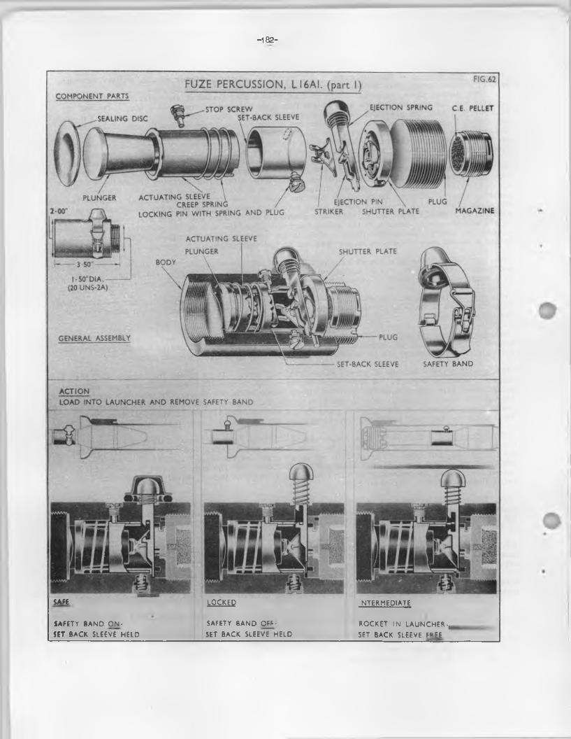
-182-
FUZE PERCUSSION, L16AI. (part I)COMPONENT PAMS
EJECTION SPRING C.E. PELLETSTOP SCREWSET-BACK SLEEVESEALING DISC
PLUNGER ACTUATING SLEEVE \ /CREEP SPRING /
LOCKING PIN WITH SPRING A N D PLUG
PLUGI EJECTION PIN \ STRIKER SHUTTER PLATE MAGAZINE
ACTUATING SLEEVE
PLUNGER SHUTTER PLATEB O D Y
PLUGGENERAL ASSEMBLY
SAFETY B A N DSET-BACK SLEEVE
A CTIO NLOAD INTO LAUNCHER AND REMOVE SAFETY B A N D
SAFE
SAFETY BAND O N SET BACK SLEEVE HELD
LOCKED
SAFETY BAND OFFSET BACK SLEEVE HELD
INTERMEDIATE
ROCKET IN LAUNCHER-, SET BACK SLEEVE FREE

'183-
FIG .63
ACTION OF SHUTTER
UNARMED
Rear view Front view
ON IMPACT
FUZE PERCUSSION, LI6AI. (part 2)ACTION
ACTION OF STRIKERON FIRING-
UNARMED
SET-BACK SLEEVE-—' STEMMED C.E.
DURING FLIGHT
ARMED
{ STRIKER ACTUATING SLEEVE
STOP SCREW
EJECTION PINSHUTTER
SHUTTER SPRINGAND PIN
ARMED
Rear view Front view
SHUTTER RETAININGSPRING
STOP SCREW ON IMPACT
C.E. PELLET EIECTION PIN
ACTUATING SLEEVE
PLUNGER
ACTUATING SLEEVE
STRIKERDETONATOR
(2-8GR AZ.)
STRIKERSHUTTER
MAGAZINE
— 1 & T “
175.During f l ig h t - The set-back sleeve and the actuating sleeve are prevented from rotating by the stop screw which passes through a s lo t provided in both sleeves. The s tr ik er spring also prevents the s tr ik er from impinging on the detonator, end the creep spring retards the forward movement o f the plunger and actuating sleeve. The action o f the creep spring is strong enough to retard the plunger and actuating sleeve and to prevent the fuze from f ir in g should the rocket strike a ligh t object such as lig h t brush or undergrowth.
174-On impact or graze - With a more resistant object the in e rtia plunger and actuating sleeve overcome the force o f the creep spring and move forward. The actuating sleeve aided by the weight o f the plunger bears on the lugs o f the triangular frame on which the str iker is mounted. The s tr ik er spring is depressed and the str iker forced on to the detonator which, in turn, detonates the C.E. p e lle t in the magazine and the f i l l i n g in the rocket head.
175.D ifferences in marks - The fo llow ing shows b r ie f ly the various d ifferences in patterns Model A1(described above)
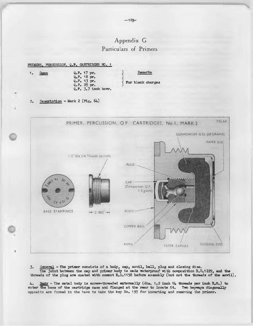
s
— 185-
Appendix G
Particulars of Primers
HtIMERS. PERCUSSION. Q.F. CARTRIDGES NO. 1
1, Guns Q.F. 17 pr.Q.F. 18 pr.Q.F. 13 pr.Q.P. 25 pr.Q.P. 3.7 inch howr.
Remarks
Por blank charges
2. Description - Mark 2 (F ig . 6l+)
i
BASE STAM PINGS b - 0-883"-H
CAP(Composition Q F..
I -2 grains)
BODY
COPPER BALL
ANVIL
PRIMER, PERCUSSION. Q.F. CARTRIDGES, No.l, MARK 2 FIG.64
G U N P O W D E R G.I2. (SO GRAINS)\
PAPER D ISC
I -2" Dia (I4 Threads per Inch)
PLUG
PAPER CAPSULE C L O S IN G D ISC
3. General - The primer consists o f a body, cap, an v il, b a ll, plug and closing disc.The jo in t between the cap and. primer body is made waterproof w ith composition R.D.1229, and the
threads o f the plug are coated with cement R.D.1158 before assembly (but not the threads o f the a n v il).
4. Body - The metal body is screw-threaded externally (d ia . 1.2 inch 14 threads per inch R.H.) to enter the base o f the cartridge case and flanged a t the rear to locate i t . Two keyways diagonallyopposite are formed in the base to take the key No. 193 fo r inserting and removing the primer.
%W :
— 1 86—
The in te r io r i s bored to aoconraxiate the cap and bored and screw-threaded on a s ligh tly la rger diameter to permit the assembly o f the anvil and plug. The space between the plug and closing disc forms the magazine which is f i l l e d with about 30 grains o f G.12 gunpowder.
5. Cap - The copper a llo y cap contains approximately 1,2 grains o f Q.F, composition pressed in and covered by a le a d -t in fo il d isc . The cap is housed in the base o f the body, being retained in position by the anvil.
6. Anvil - The metal anvil is threaded externally to screw into the primer body. The in te r io r hasa p a ra lle l, then a coned and a smaller p a ra lle l central bore (to house the b a ll ) from whence two f ir echannels conneot to the raised rounded anvil surface a t the rear end.
A screwdriver s lo t is formed in the forward end.
7. B a ll - The so ft copper b a ll rests loosely in the coned portion o f the anvil.
8. Plug - The metal plug i s threaded to engage in the body and bears against the open end o f thean vil, thus retain ing the b a ll. The plug has 2 holes d r ille d through i t to form f i r e channels (p r io r to September, 1942 the plugs o f mark 2 primers were made with 3 f i r e holes).
A paper oapsule i s placed over the plug and boss formed in the base o f the primer body, and is secured in position by shellao adhesive.
9. Closing disc - The closing disc is o f brass, cup-shaped, with 6 rad ia l s l i t s across the centre. An o i l varnish paper d isc , a ffix ed by i t s edges, to the outer surface.
A fte r the magazine portion o f the body i s f i l l e d , the closing disc is f i t t e d in to the mouth o f the body, the edges o f which are turned over to reta in the disc in position . The exposed surface o f the o i l varnished paper disc including the turned over jo in t o f the body i s then coated with varnishR.D.1219.
10. Aotion - The str iker o f the f ir in g mechanism is driven on to the percussion cap and the compos it ion i s nipped on the an vil. The flame passes through the f i r e channels in the an vil, past the b a ll, through the f i r e holes in the plug, and through the paper capsule to ign ite the gunpowder in the body o f the primer. The resultant explosion forces the b a ll back in to i t s seating, preventing rearward gas escape, by sealing the f i r e holes in the anvil; and the flame from the magazine forces open the s l i t s in the closing disc and ign ites the propellant charge.
1 1 . Particu lars o f various marks - The fo llow ing b r ie f ly shows the various d ifferences in patterns
Mark 2MThis i s the mark 2 primer repaired by f i t t in g a new cap, an v il, copper b a ll and plug.
The base i s indented to bring the cap chamber up to the mark 2 and the metal a t the mouth is thinned down to fa c i l i t a t e turning over a fte r r e - f i l l in g , and a new closing d isc is f i t te d . The primer is f i l l e d with about 45 grains o f G,12 powder
NOTE:- MQ" i s stamped on the base o f primers assembled with caps f i l l e d with Q.F. compos ition .
Mk. 1 )Mk. 1 * )Mk. 1HR 1Mk. 2A }Mk. 2B )Mk. 2AB )Mk. 2AT )Mk. 2BT )Mk. 2MB )Mk. 2MR )Mk. 2MRM )Mk. 2MRMT )Mk. 2MRT }Mk. 2MT )Mk. 2R )Mk. 2RB )
Mk. 2RRM Mk. 2RRMT Mk. 2ERT Mk. 2KT Mk. 2T Mk. 2*Mk. 2*B Mk. 2*M Mk. 2*MB Mk. 2*MR Mk. 2*MRT Mk. 2*M Mk. 2*R Mk. 2*RT Mk. 2*T Mk. 3
Mk. 3BMk. 3RMk. 3RBMk. 3RRMk. 3RRTMk. 3RTMk. 3TMk. 4Mk. 4BMk. 4TMk. 5Mk. 6Mk. 6BMk. 6TMk. 7 )
Obsolete ObsoleteObsolete I
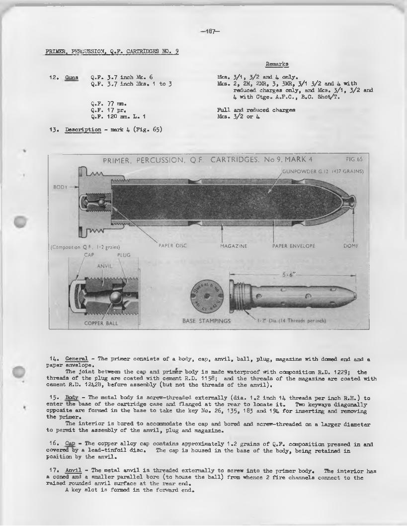
187—
PRIMER. PERCUSSION. Q.F. CARTRIDGES NO. 9
Remarks
12. Guns Q.F. 3 *7 inch Mk. 6 Mks.Q.F. 3.7 inch Mks. 1 to 3 Mks.
Q.F. 77 nro.Q.F. 17 pr. Fu llQ.F. 120 mm. L . 1 Mks.
3/1 > 3/2 and 4 only.2, 2M, 2MR, 3, 3MR, 3/1 3/2 and 4 with reduced charges only, and Mks. 3/l» 3/2 and 4 with Ctge. A .P.C ., B.C. Shot/T.
and reduced charges 3/2 or 4
13* Description - mark 4 (F ig * 63)
(Composition Q.F . I -2 grains) PAPER DISC MAGAZINE PAPER ENVELOPE DOME
BODY
PRIMER, PERCUSSION, Q.F. CARTRIDGES, No 9. MARK 4 R G .6 5
GUNPOWDER G.I2. (437 GRAINS)
CAP PLUG
14* General - The primer consists o f a body, cap, anvil, b a ll, plug, magazine with domed end and a paper envelope.
The jo in t between the cap and primer body is made waterproof with composition R.D. 1229; the threads o f the plug are coated with cement R.D. 1158; and the threads o f the magazine are coated with cement R.D. 1242B, before assembly (but not the threads o f the a n v il).
15. Body - The metal body is screw-threaded externally (d ia . 1.2 inch 14 threads per inch R.H.) toenter the base o f the cartridge case and flanged at the rear to locate i t . Two keyways diagonallyopposite are formed in the base to take the key No. 26, 135, 183 and 194 fo r inserting and removing the primer.
The in te r io r is bored to accommodate the cap and bored and screw-threaded on a la rger diameter to permit the assembly o f the an v il, plug and magazine.
16. Cap - The copper a llo y cap contains approximately 1.2 grains o f Q.F. composition pressed in a » l covered by a le a d -t in fo il d isc . The cap is housed in the base o f the body, being retained in position by the anvil.
17* Anvil - The metal anvil i s threaded externally to screw into the primer body. The in te r io r has a coned and a smaller p a ra lle l bore (to house the b a ll) from whence 2 f i r e channels connect to the raised rounded anvil surface at the rear end.
A key s lo t is formed in the forward end.
— 1 O S-
18. B a ll - The so ft copper b a ll rests loosely in the coned position o f the anvil.
19. Plug - The metal plug is threaded to engage in the body and bears against the open end o f the anvil, thus retain ing the b a ll. The plug is bored cen tra lly to form a f i r e channel and also diagonally to form three smaller f i r e channels to connect the central main f i r e channel to an annular groove on the rear face.
A screwdriver s lo t is formed on the forward end.A paper disc is a ffix ed by shellac over the other end o f the plug and on to the body.
20. Magazine - The cy lind rica l brass magazine is rounded at the front and screw-threaded externally at the rear to engage in the body. I t is perforated with sixteen rad ia l f i r e holes along the sides and one f i r e hole in the front end, the la t te r being closed by a white-metal dome secured in position by pressing over the top. The white-metal dome is provided to prevent accidental perforation o f the magazine by a stick o f the propellant charge, i t also acts as a decoppering agent.
The in te r io r o f the magazine is f i t t e d with an envelope o f shellacked paper or other approved material which is secured in position by shellac adhesive.
The magazine is f i l l e d with 437 grains o f G12 gunpowder.
ACTION21 • The str iker o f the f ir in g mechanism is driven on to the percussion cap and the composition is
nipped on the anvil. The flame passes through the f i r e channels in the an vil, past the b a ll, through the holes in the plug and through the paper disc to ign ite the gunpowder in the magazine.The resultant explosion forces the b a ll back into i t s seating, preventing rearward gas escape,, and the flame passes through the holes o f the magazine to ign ite the propellant charge.
22. D ifference in marks - The fo llow ing shows b r ie f ly the variolas d ifferences in patterns Mark 3
This d if fe rs from the mark 4 by having a copper cone instead o f a b a ll in the anvil.The dimensions o f the plug are also s lig h t ly modified. This mark o f primer is res tr ic ted to Q.Po 3.7 inch Mks. 1 to 3 , 17 p r. and 3*7 inch R.C.L. guns.
Mark 3/1 (Obsolescent)This is exactly the same as the mark 3 except that a copper b a ll replaces the coned plug,
and the magazine is f i t t e d with a "Hawley" lin e r .
««■ * 3/2This is sim ilar to the mark 3/1 d if fe r in g only that i t is provided with a new pattern
anvil designed to improve performance and sealing.
Marks 3M and 3MRThese are mark 3 primers repaired by f i t t in g new magazine domes and cone plug sealing
mechanisms, and s ligh t a lterations to the body.
Mark 2 (obsolescent)This d if fe r s from the mark 3 only in dimensions o f the anvil and cone. The mark 3 is
also f i t t e d with a plug o f modified design. The plug fo r the Mk. 2 had two f i r e holes.
Mark 2M and 2MRThese are mark 2 primers repaired as necessary by f i t t in g new an v il, screwed plug,
magazine dome, and soft copper coned plug.
Mark 1This d if fe rs from the mark 2 by having a copper b a ll instead o f a cone plug, the anvil
having a 3»7° conical bore.
Marks 1M and 1MRThese are mark 1 primers repaired as necessary by f i t t in g new an vil, screwed plug,
magazine dome and b a ll . The screwed plug had 3 f i r e holes.
NOTE:- "Q" is stamped on the base o f primers assembled with caps f i l l e d with Q.F. composition.
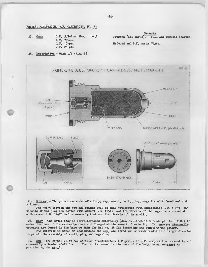
-18 9 -
Remarks23. Guns Q.P. 3 o7 -in ch Mks. 1 to 3 Primers ( a l l marks). Pu ll and reduced charges.
Q.F. 77-mm.Q. P. 17-pr. Seduced and B.E. smoke Ctges.Q.P. 25-pr.
24. Description - Mark h/‘1 (P ig . 66)
PRIMER. PERCUSSION. Q.F. CARTRIDGES. NO. 11
PRIMER, PERCUSSION, Q.F. CARTRIDGES. No. 11, MARK 4/I
CAP(Composition Q.F
I -2 grains)
BODY
M AGAZINE
DOME
PAPER DISC
LINER
GUNPOWDER G.I2 (l64 GRAINS)
COPPER BALL PLUG
I *2 Dia (I4 Threads per inch)
CAP ANVIL
BASE STAMPINGS— 2 •526"
25. General - The primer consists o f a body, cap, an v il, b a ll, plug, magazine with domed end and a lin er.
The jo in t between the cap and primer body is made waterproof with composition S.D. 1229; the threads o f the plug are coated with cement R.D. 1158; and the threads o f the magazine are coated with cement P .D , 1242B before assembly (but not the threads o f the a n v il).
26. Body - The metal body is screw-threaded externally (d ia . 1.2-inch 14 threads per inch R.H.) to enter the base o f the cartridge case and flanged at the rear to locate i t . Two keyway a diagonally opposite are formed in the base to take the key No. 25 fo r inserting and removing the primer.
The in terio r is bored to accommodate the cap, and bored and screw-threaded on a la rger diameter to permit the assembly o f anvil, plug and magazine.
27. Cap - The copper a llo y cap contains approximately 1.2 grains o f Q.P. conposition pressed in arri. covered by a le a d -t in fo il disc. The cap is housed in the base o f the body, being retained in position by the anvil.
- 1 9 0 -
28. Anvil - The metal anvil is threaded externally to screw into the body. The in te r io r has a coned ard a small p a ra lle l bore (to house the b a l l ) from whence 2 f i r e channels connect to the raised rounded anvil surface at the rear end. A key s lo t is formed in the forward end.
29° B a ll - The so ft copper b a ll rests loosely in the coned portion o f the anvil.
30. Plug - The metal plug is threaded to engage in the body and bears against the open end o f the anvil, thus retain ing the b a ll. The plug is bored cen tra lly to form a f i r e channel and also diagonally to form three smaller f ir e channels to connect the centre main f ir e channel to an annular groove on the rear face. A screwdriver s lo t i3 formed on the forward end.
31. Magazine - The magazine is cy lin d rica l, rounded at the front and screw-threaded externally at the rear to engage in the body0 I t is perforated w ith eight rad ia l f i r e holes along the sides and one f ir e hole in the front end, the la t te r being closed by a white-metal dome secured in position by s ligh tly pressing over the tqp0 The white-metal dome is provided to prevent accidental perforation o f the magazine by a stick o f the propellant charge, i t also acts as a decappering agent.
The in te r io r o f the magazine is f i t t e d with a lin e r o f shellacked paper or other approved material which is secured in position by Shellac Adhesive0
The magazine is f i l l e d with about 164 grains o f 1 12 gunpowder.
32. Action - The str iker o f the f ir in g mechanism is driven on to the percussion cap and the composition is nipped on the anvil. The flame passes through the f ir e channels in the an v il, past the b a ll, through the f i r e holes in the plug and through the paper disc to ign ite the gunpowder in the magazine. The resultant explosion forces the b a ll back into i t s seating in the an v il, preventing rearward gas escape, and the flame passes through the holes in the magazine to ign ite the propellant charge.
33. D ifference in marks - The fo llow ing shows b r ie f ly the various d ifferences in patterns:-
Mark 4 (Obsolescent)This is sim ilar to the mark k/A except that i t is f i t t e d with a "Hawley" lin e r which is
now obsolete.
Mark 3/2These are empty Mk.3 primers which at time o f f i l l i n g are assembled with a b a ll instead
o f the orig ina l cone plug, and are f i t t e d w ith a polythene lin e r.
Mark 3This d if fe rs from the mark 4 in having a copper cone instead o f a b a ll in the anvil.
The dimensions o f the plug and body are also s ligh tly modified.
Mark 3/1This d if fe rs from the mark 3 only in being f i t t e d with a moulded paper "Hawley" lin e r
(now obsolete) or a moulded polythene lin er.
Mark 3M and 3MRThese are mark 3 primers repaired by f i t t in g new magazine, dome, and cone seal mechanism.
Mark 2 (obsolescent)This d if fe rs from the mark 3 in being f i t t e d with a d iffe ren t design o f plug and in
the dimensions o f anvil and cone.
Mark 2M and 2MRThese are mark 2 primers repaired as necessary by f i t t in g new an vil, screwed plug,
magazine dome and so ft copper cone plug.
Mark 1This d if fe r s from the mark 2 primer in having a soft copper b a ll instead o f a cone plug,
and in the anvil being shaped in tern a lly to suit the b a ll.
Mark 1MThis i s the mark 1 primer repaired by f i t t in g a new an v il, b a ll, magazine dome and plug.
Mark 1MRThis is the mark 1M primer repaired by f i t t in g a new an v il, b a ll, magazine dome and plug,
the anvil and plug being o f increased diameter and the screw-threaded recess in the body being opened out to accommodate them.
NOTE:- "A" is starrped on the base o f primers assembled with caps f i l l e d with Q.P. composition.
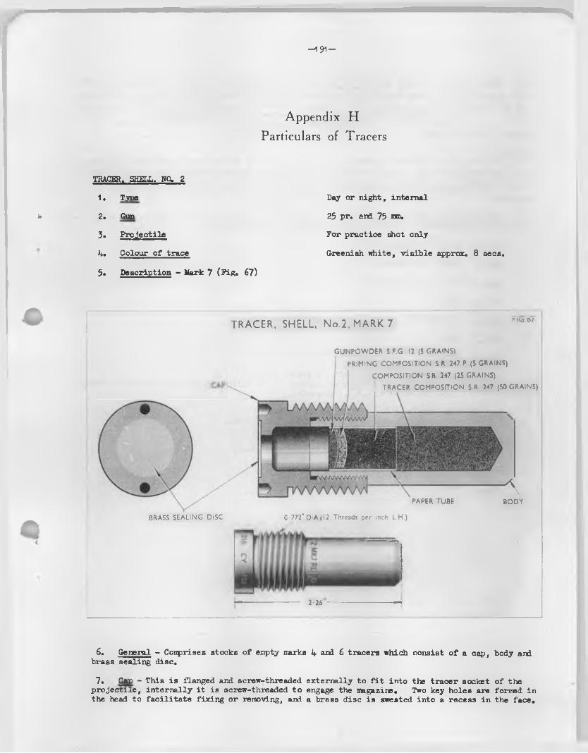
s- 1 9 1 -
Appendix H
Particulars of Tracers
TRACER. SHEI.L. NO. 2
1. Type
* 2. Gun
3. P ro jec tile
if. Colour o f trace
5. Description - Mark 7 (F ig . 67)
Day or night, internal
25 pr. and 75 nm.
For practice shot only
Greenish white, v is ib le approx. 8 secs.
ABODY
BRASS SEALING DISC
TRACER, SHELL, No.2, MARK 7 rKa0/
GUNPOWDER S.F.G. 12 (5 GRAINS)
PRIMING COMPOSITION SR 247 P (5 GRAINS)
COMPOSITION SR. 247 (25 GRAINS)! TRACER COMPOSITION S.R. 247 (50 GRAINS)
PAPER TUBE
0-772” D!A.(12 Threads per inch L.H.)
. ^ xxA
2-26 ---------
6. General - Conprises stocks o f empty marks 4 and 6 tracers which consist o f a cap, body and brass sealing disc.
7. Cap - This is flanged and screw-threaded externally to f i t in to the tracer socket o f thep ro je c t ile , in tern a lly i t is screw-threaded to engage the magazine. Two key holes are formed inthe head to fa c i l i ta te fix in g or removing, and a brass disc is sweated into a recess in the face.
8. Body - The body is cy lin d rica l and screw threaded externally at the open end to engage in the cap. In terna lly i t is bored to accommodate the f i l l i n g which consists o f 50 grains o f tracer composition S.R. 247 pressed home in two increments, th is is followed by a pre-pressed p e lle t consisting o f 25 grains o f conposition S.R. 247 , 5 grains o f priming conposition S.R.247P, and 5 grains o fS. F.G. 12 gunpowder inserted in a wax inpregnated paper tube. The p e lle t is inserted and pressed in on top o f the tracer composition, leaving a space between the fin a l surface o f the gunpowder and the recess bored in the cap.
Action: -9. On f ir in g , the brass disc covering the flash hole in the cap is blown in and the flash from
the propellant charge ign ites the gunpowder and priming conposition which, in turn, ign ites the tracer conposition. When the p ro je c t ile leaves the muzzle o f the gun, the flame from the tracer conposition escapes through the flash hole thus enabling the f l ig h t o f the p ro je c t ile to be observed.
10. Particu lars o f various marks - Various marks have been a llocated to th is nature o f tracer, the main d ifferences between the Land Service patterns are tabulated below:-
Mark 1
Mark 2
Mark 6 Sim ilar
S.R.261C with
Mark 6R D iffers
Mark 6S D iffers
Naval, (obsolescent)
Naval, (obsolescent)
Naval. ( obsole3cent)
Naval.
Land Service, (obsolescent) fo r practice only.
Naval
Naval
Land Service, (obsolescent) fo r practice only.to the mark 4 but d iffe r in g p rin c ipa lly in the f i l l i n g , the tracer conposition being a fin a l increment o f S.F.G.2 gunpowder.
Land Servicefrom the mark 6 only in being made from Ledloy stee l.
Land Servicefrom the mark 6 only in being made from mild s tee l.
Mark 8 Naval
Mark 9 Naval
—193—
TRACER. S ^ L . NO. 37
11. Type F lat base, 4 channel
12. Gun 25 pr.
13. P ro je c tile HESH
14. Colour o f trace Red
15. Description - Mark 1 (F ig . 68)
PRIMING COMPOSITION SR 399
CARNAUBA W AX
BASE STAMPINGS
BODY
TRACER, SHELL, No.37, MARK I FIG.683 PELLETSTRACER COMPOSITION S.R 247A
PLUG
W AXED PAPER TUBE
16. General - The tracer is made o f s tee l and is in the form o f a f la t disc. Four holes equally spaced are d r ille d through the disc to enable the tracer to be a ffix ed by screws to the base o f the projectile,,
In terna lly , i t is d r ille d form 4 longitud inally cav it ies to contain the tracer composition, these cav ities terminating in a hole d r ille d centra lly in the base o f the trace. The mouths o f the cav ities are closed, a fte r f i l l in g by screw-threaded s tee l plugs. The central hole formed in the base is closed by a thin brass disc which is secured, a fte r the cav ities are f i l l e d by turning over a bezel, the disc and bezel being coated with composition R.D.1229. The faces o f the 4 plugs and the sealing disc are painted red a fte r f i l l in g .

- 1 9 * -
17. F i l l in g - Each cavity is lined with a wax inpregnated paper tube into which is inserted (reading from the centre hole) 1 pre-pressed p e lle t o f priming conposition S.E. 399 weighing approximately 20 grains, 3 pre-pressed p e lle ts o f tracer conposition S.E.372AB each weighing approximately 16 grains, followed by 1 p e lle t o f camauba wax weighing approximately 3 grains. The screw threads o f the plugs are coated with cement R.D. 1248, they are then inserted and screwed home.
18. Action - On f ir in g , the brass disc over the emission hole in the centre o f the base is blown in and the flash from the propellant charge ign ites the priming conposition in each o f the four cav ities which, in turn, ign ites the tracer conposition.
When the p ro je c t ile leaves the muzzle the flame from the tracer conposition in the four cav it ies escapes through the central emission hole and enables the flig h t o f the p ro je c t ile to be observed.
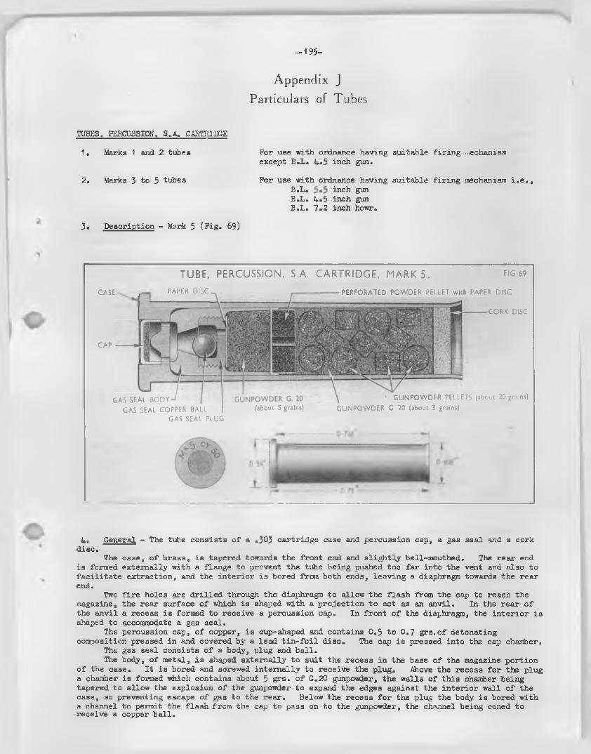
-1 9 5 -
Appendix J
Particulars of Tubes
TUBES, PERCUSSION. S.A. CARTRIDGE
1. Marks 1 and 2 tubes For use with ordnance having suitable f ir in g mechanismexcept B.L. 4*5 inch gun.
2. Marks 3 to 5 tubes For use with ordnance having suitable fir in g mechanism i . e . ,B.L. inch gun B.L. 4.5 inch gun B.L. 7.2 inch howr.
3. Description - Mark 5 (P ig . 69)
CASE
TUBE, PERCUSSION, S.A. CARTRIDGE, MARK 5. HG.69PAPER D IS C -. .-------------------------PERFORATED POWDER PELLET with PAPER DISC
CORK DISC
CAP
GAS SEAL BODYGAS SEAL COPPER BALL
GAS SEAL PLUG(about 5 grains)
' GUNPOWDER PELLETS (about 20 grains) GUNPOWDER G. 20 (about 3 grains)
4. General - The tube consists o f a .303 cartridge case and percussion cap, a gas seal and a cork disc.
The case, o f brass, is tapered towards the front end and s lig h t ly bell-mouthed. The rear end is formed externally with a flange to prevent the tube being pushed too fa r into the vent and also to fa c i l i ta te extraction, and the in te r io r is bored from both ends, leaving a diaphragm towards the rear end.
Two f i r e holes are d r il le d through the diaphragm to allow the flash from the cap to reach the magazine, the rear surface o f which is shaped with a projection to act as an anvil. In the rear o f the anvil a recess is formed to receive a percussion cap. In front o f the diaphragm, the in te r io r is shaped to accommodate a gas seal.
The percussion cap, o f copper, is cup-shaped and contains 0.3 to 0.7 g rs .o f detonating composition pressed in and covered by a lead t in - fo i l d isc. The cap is pressed into the cap chamber.
The gas seal consists o f a body, plug and b a ll.The body, o f metal, is shaped externally to suit the recess in the base o f the magazine portion
o f the case. I t is bored and screwed in terna lly to receive the plug. Above the recess fo r the plug a chamber is formed which contains about 5 grs. o f G.20 gunpowder, the walls o f th is chamber being tapered to allow the explosion o f the gunpowder to expand the edges against the in terio r wall o f the case, so preventing escape o f gas to the rear. Below the recess fo r the plug the body is bored with a channel to permit the flash from the cap to pass on to the gunpowder, the channel being coned to receive a copper b a ll.
—196—
The plug, o f metal, is screw-threaded externally to su it the thread in the body, three f i r e - holes being bored through from front to rear. The under surface is recessed and formed rectangular in shape to allow clearance fo r the copper b a ll.
The b a ll, o f so ft copper, is spherical in shape and seals the channel in the body, a fter explosion o f the gunpowder.
A fin e white paper disc is secured by shellac to the top o f the plug, whilst a perforated powder p e lle t is secured above the gunpowder by shellac adhesive.
The main magazine o f the tube is above the perforated powder p e lle t and consists o f 20 grs. o f powder p e lle ts (o r a ltern a tive ly G7 gunpowder) the in terstices being f i l l e d in with 3 grs. o f G.20 gunpowder.
The mouth o f the tube is closed with a disc o f cork or cork substitute, the disc being coated with varnish before insertion and the exposed side being afterwards waterproofed with approved varnish.
5* Action - When the percussion mechanism is operated, the cap in the base o f the tube is struck by the point o f the f ir in g pin, causing the cap composition to be nipped between the anvil and the in te r io r base o f the car), and thus fire d . The resu lting flash passes through the holes in the body diaphragm and plug to ign ite the powder in the magazine which, in turn, blows out the cork closing plug and ign ites the cloth ign ite r attached to the base o f the propellant charge.
The so ft copper b a ll is driven to the rear by the explosion in the magazine and the w alls o f the tube are expanded rad ia lly so preventing escape o f gas to the rear from the tube chamber in the vent. The b a ll seal prevents internal gas escape through the head o f the tube; where th is is absent as in the marks 1 and 2, the percussion cap fu l f i l s th is function.
6. D ifferences in marks - The fo llow ing shows b r ie f ly the various d ifferences in patterns:- Mark 1 (obsolescent)
Consists o f a .303 inch brass case with percussion cap, containing a charge o f about 30 grs. o f so lid gunpowder p e lle ts , the mouth o f the case being closed by a cork disc or plug which is coated with shellac varnish before insertion , the exposed surface being afterwards waterproofed by shellac. This is a necked tube.
Length 2.222 inch diameter .460 inch under head,'.34 inch at mouth.
Mark 2 (obsolescent)D iffe rs from the mark 1 in the f i l l i n g which consists o f 13 grs. G.20 gunpowder in a
paper container and approximately 29 grs. so lid powder p e lle ts with loose G.20 gunpowder in the in terstices . The mouth is closed as fo r the mark 1 tube.
The shape and dimensions are the same as fo r the mark 1.
Mark 3 (obsolescent)D iffe rs from the mark 2 in the tube not being necked and in having an internal gas seal
metal body and plug, w ith copper b a ll and in the f i l l in g . The gas seal body is bored out and provided with a screwed recess to house the plug, the la t te r being f i t t e d with a so ft copper ba ll which prevents escape o f gas a fte r f ir in g . Three holes are bored in the plug to allow the flash to pass from the cap to the body. The f i l l in g consists o f approximately 5 grs. o f G.20 gunpowder in the top portion o f the body with a perforated powder p e lle t interposed between i t and 20 grs. powder p e lle ts (o r a ltern a tive ly G.7 powder) in the brass case, the in terstices being f i l l e d in with approximately 3 grs. loose G.20 gunpowder.
Length 1.79 inches, diameter .460 inch under head .401 inch at mouth.
Mark 3A (obsolescent)This is a converted mark 3 tube.The conversion consists o f f i t t in g a modified gas seal plug. The shape and dimensionsare the same as fo r the mark 3 tube.
Mark 4 (obsolescent)Generally sim ilar to the mark 3 tube d if fe r in g p rin c ipa lly in that the channel in the gas
seal to receive the copper b a ll has a la rger chamfer, the b a ll conpletely entering the channel improving the sealing e f fe c t .
The shape and dimensions are the same as fo r the mark 3 tube.
Mark 4AThis is a converted mark 4 tube and d if fe rs only in that the recess in the plug fo r the
copper b a ll is rectangular in shape, thus allowing more movement o f the b a ll.
Mark 3Generally sim ilar to the mark 4A tube, but is o f new manufacture.

%

-
r
Ai
l
i
/ V * '
\
r
Recommended