Flow-Induced Vibration Analysis of Supported Pipes with a Crack
Jin-Hyuk Lee, Samer Masoud Al-Said
Department of Mechanical Engineering
American University of Sharjah, UAE
• Introduction and Motivation
• Aeroacoustically fluid-structure interaction Mathematical Formulation
Fluid loading effect
Viscous friction effect due to flowing fluid inside a pipe
FEA (Finite Element Analysis) model
• Preliminary Results• Conclusion• Future Work• Q & A
2
Outline
3
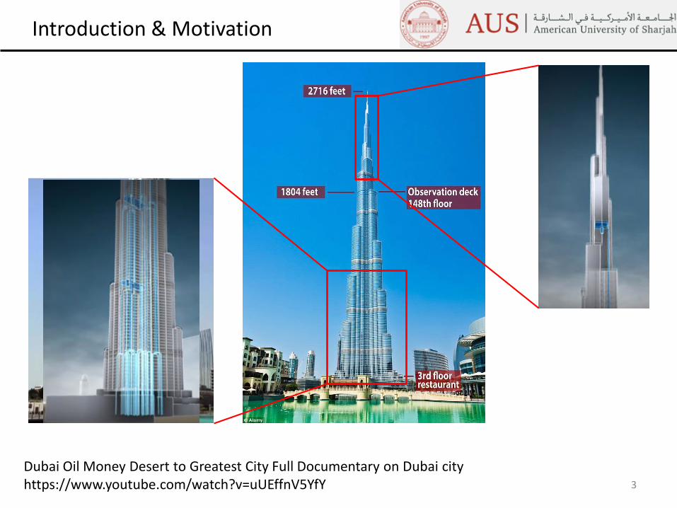
Introduction & Motivation
Dubai Oil Money Desert to Greatest City Full Documentary on Dubai cityhttps://www.youtube.com/watch?v=uUEffnV5YfY
4
Introduction & Motivation
The effect of a crack to the flow-induced vibration characteristics of supported pipes isinvestigated based on vibration method.
We need to utilize the variation of the difference between the natural frequencies of thepipe conveying fluid with and without a crack.
The pipe is fluid loaded via interaction with the fluid.
Fluid loading has two main effect on vibrating pipes:1. Fluid mass loads the pipe, i.e., the pipe’s natural frequencies are altered2. Viscous loading is provided to the pipe near the inner wall due to shear force
COMSOL Multiphysics®1. Aeroacoustics Module2. Structural Moduel
5
Mathematical Model
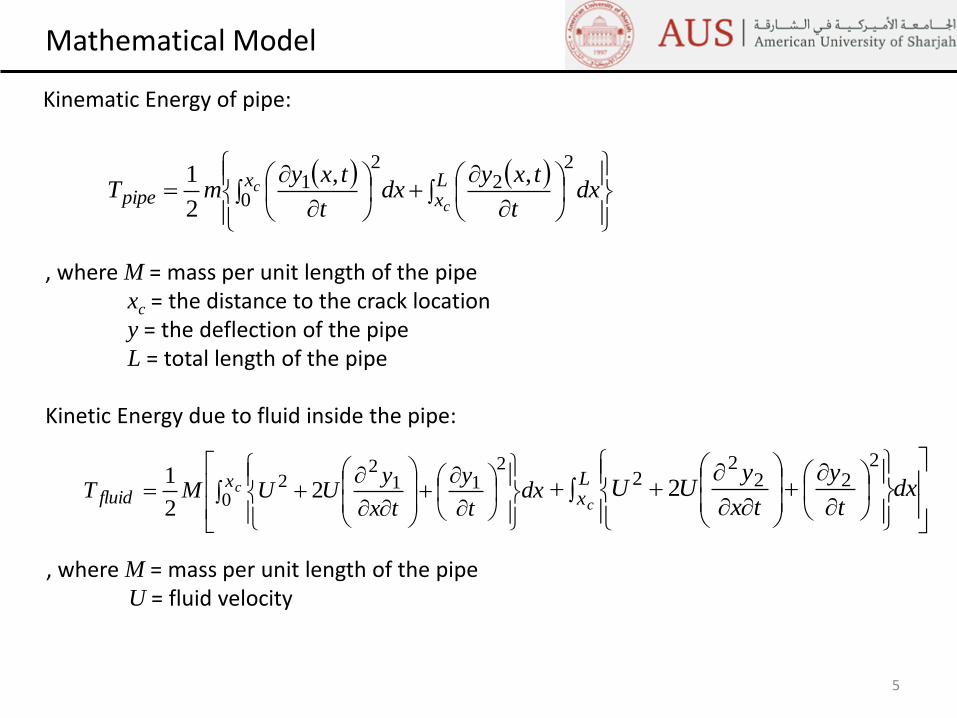
Kinematic Energy of pipe:
, where M = mass per unit length of the pipexc = the distance to the crack locationy = the deflection of the pipeL = total length of the pipe
Kinetic Energy due to fluid inside the pipe:
Lx
xpipe
c
c dxt
txydx
t
txymT
22
2
01 ,,
2
1
dxt
y
tx
yUUMT cx
fluid
0
211
22 2
2
1
dx
t
y
tx
yUUL
xc
222
22 2
, where M = mass per unit length of the pipeU = fluid velocity
6
Mathematical Model (cont’d)
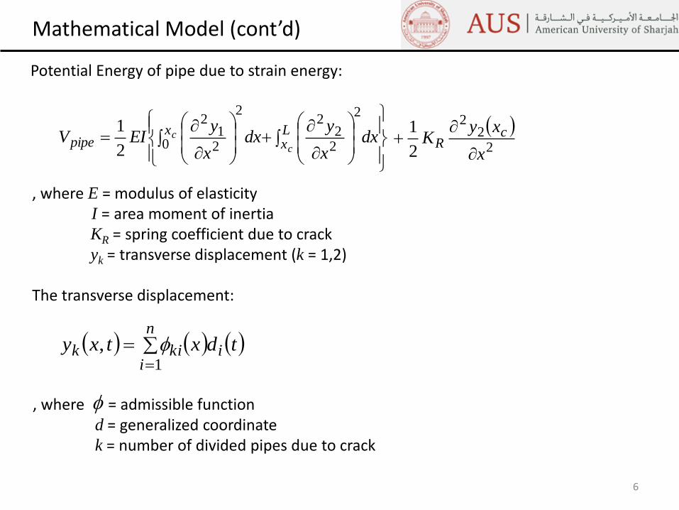
Potential Energy of pipe due to strain energy:
, where E = modulus of elasticityI = area moment of inertiaKR = spring coefficient due to crackyk = transverse displacement (k = 1,2)
The transverse displacement:
, where = admissible functiond = generalized coordinatek = number of divided pipes due to crack
dx
x
ydx
x
yEIV L
xx
pipec
c
2
22
22
0 21
2
2
1 2
22
2
1
x
xyK c
R
n
iikik tdxtxy
1
,
7
Mathematical Model (cont’d)
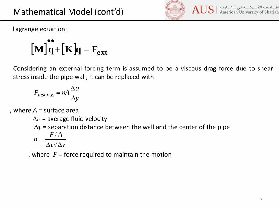
Lagrange equation:
, where A = surface area∆ʋ = average fluid velocity∆y = separation distance between the wall and the center of the pipe
Considering an external forcing term is assumed to be a viscous drag force due to shearstress inside the pipe wall, it can be replaced with
, where F = force required to maintain the motion
extFqKqM
yAFviscous
y
AF
GEOMETIC MODEL AND
BOUNDARY CONTIDIONS
8
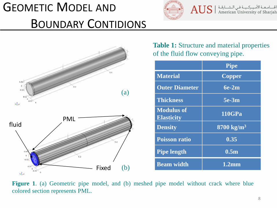
Pipe
Material Copper
Outer Diameter 6e-2m
Thickness 5e-3m
Modulus of
Elasticity110GPa
Density 8700 kg/m3
Poisson ratio 0.35
Pipe length 0.5m
Beam width 1.2mm
Table 1: Structure and material properties
of the fluid flow conveying pipe.
Figure 1. (a) Geometric pipe model, and (b) meshed pipe model without crack where blue
colored section represents PML.
Fixed
PMLfluid
(a)
(b)
FSI PROBLEM IN
FREQUENCY DOMAIN
Infinite boundary (absorb boundary):
PML
Fluid-structure interaction (FSI) boundary:
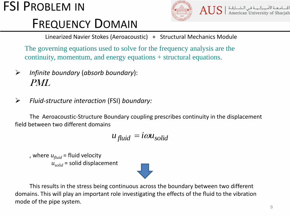
The Aeroacoustic-Structure Boundary coupling prescribes continuity in the displacement field between two different domains
, where ufluid = fluid velocityusolid = solid displacement
This results in the stress being continuous across the boundary between two different domains. This will play an important role investigating the effects of the fluid to the vibration mode of the pipe system.
Structural Mechanics ModuleLinearized Navier Stokes (Aeroacoustic) +
9
The governing equations used to solve for the frequency analysis are the
continuity, momentum, and energy equations + structural equations.
solidfluid uiu
CRACK GEOMETRY
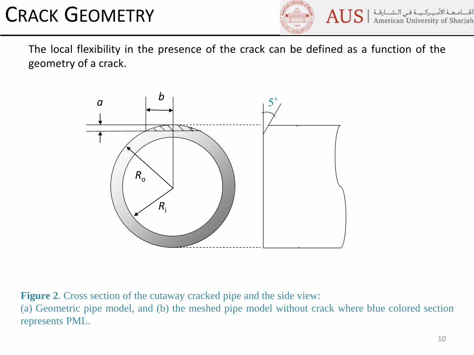
The local flexibility in the presence of the crack can be defined as a function of thegeometry of a crack.
10
Figure 2. Cross section of the cutaway cracked pipe and the side view:
(a) Geometric pipe model, and (b) the meshed pipe model without crack where blue colored section
represents PML.
5˚
Ri
Ro
ba
11
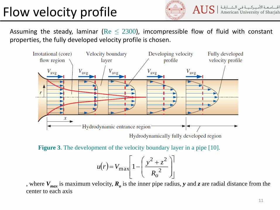
Flow velocity profileAssuming the steady, laminar (Re ≤ 2300), imcompressible flow of fluid with constantproperties, the fully developed velocity profile is chosen.
Figure 3. The development of the velocity boundary layer in a pipe [10].
2
22
max 1
oR
zyVru
, where Vmax is maximum velocity, Ro is the inner pipe radius, y and z are radial distance from the
center to each axis
CRACK MESHING AND FLOW
BOUNDARY CONTIDIONS
12
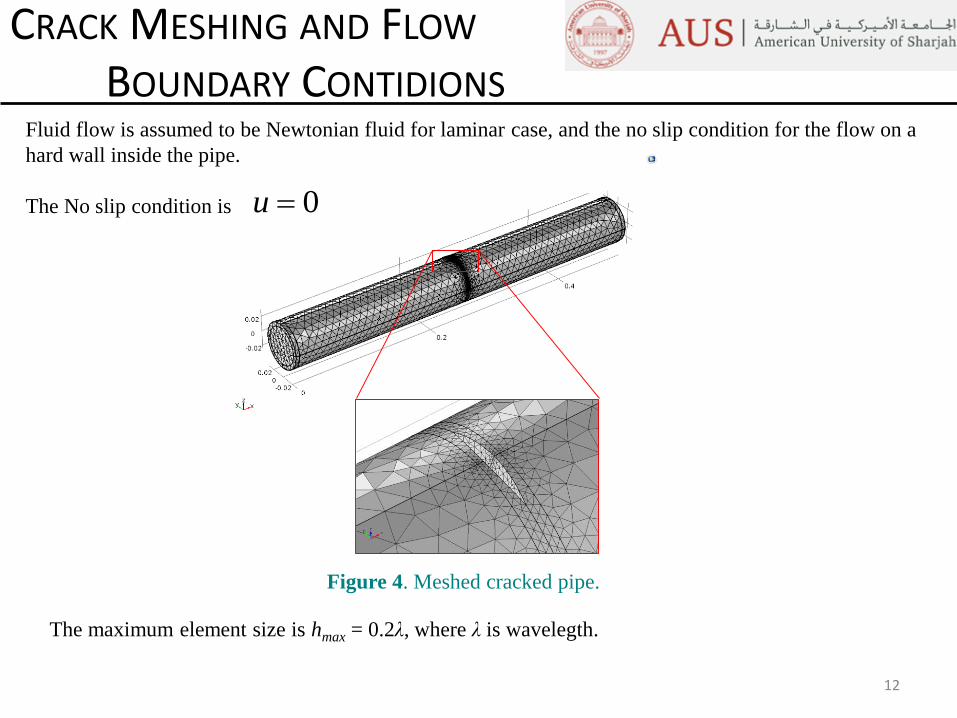
Fluid flow is assumed to be Newtonian fluid for laminar case, and the no slip condition for the flow on a
hard wall inside the pipe.
The No slip condition is 0u
Figure 4. Meshed cracked pipe.
The maximum element size is hmax = 0.2λ, where λ is wavelegth.
13
Simulation Results: Fluid loading & Crack Effects
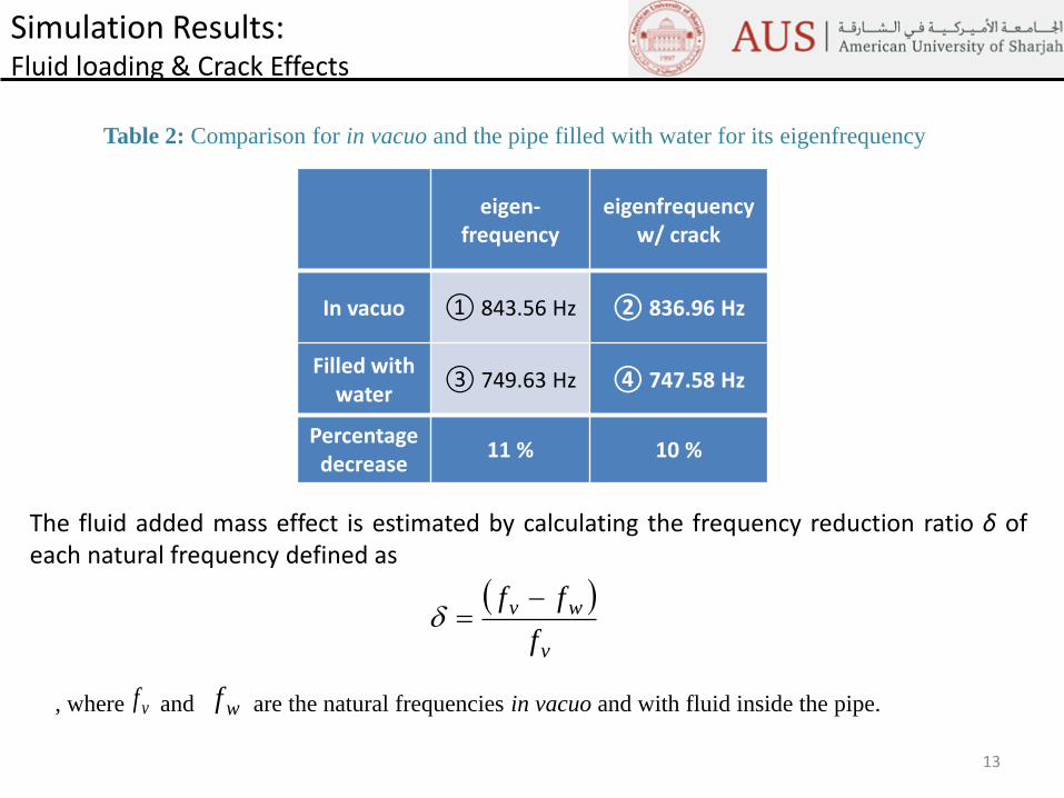
eigen-frequency
eigenfrequencyw/ crack
In vacuo ① 843.56 Hz ② 836.96 Hz
Filled with water
③ 749.63 Hz ④ 747.58 Hz
Percentage decrease
11 % 10 %
v
wv
f
ff
vf wf, where and are the natural frequencies in vacuo and with fluid inside the pipe.
Table 2: Comparison for in vacuo and the pipe filled with water for its eigenfrequency
The fluid added mass effect is estimated by calculating the frequency reduction ratio δ ofeach natural frequency defined as
14
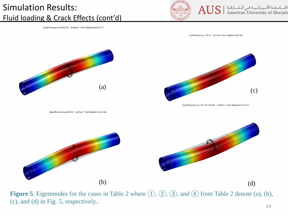
Simulation Results: Fluid loading & Crack Effects (cont’d)
(a)
(b)
(c)
(d)
Figure 5. Eigenmodes for the cases in Table 2 where ①, ②, ③, and ④ from Table 2 denote (a), (b),
(c), and (d) in Fig. 5, respectively..
15
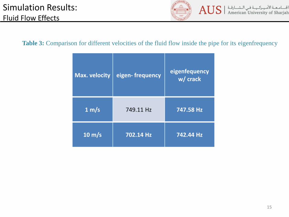
Simulation Results: Fluid Flow Effects
Max. velocity eigen- frequencyeigenfequency
w/ crack
1 m/s 749.11 Hz 747.58 Hz
10 m/s 702.14 Hz 742.44 Hz
Table 3: Comparison for different velocities of the fluid flow inside the pipe for its eigenfrequency
16
Conclusion
In this paper, a pipe conveying fluid flow with crack has beeninvestigated through numerical simulation using COMSOL Multiphysicssoftware.
Vibrational behavior of the pipe system has been studied to show theeffect of fluid within a pipe as well as that of crack.
Due to the added mass effect induced by the fluid inside the pipe, asignificant reduction in natural frequencies is observed (Table 2).
The velocity of the fluid inside the pipe seems to affect the naturalfrequency of the pipe system such that as the velocity increases, itseigenfrequency decreases. However, there has not been found any specificcorrelation between them in this work.
17
Future Work
The work to be done in the future would be as follows;
(1) investigation of further study of the velocity of the fluid flow in
greater detail,
(2) investigation of the crack location,
(3) study of dual crack effect rather than single crack, and
(4) derivation of mathematical model that corresponds with the
simulation study.
18
Q & A
Thank you!
Recommended


![Dynamic Behavior of Axially Functionally Graded Pipes ...pipes conveying fluid with simply supported ends. Zhang et al. [14] presented a viscoelastic finite element approach to the](https://img.pdfslide.net/doc/110x75/60c3e5065b18141ae64f6a56/dynamic-behavior-of-axially-functionally-graded-pipes-pipes-conveying-fluid.jpg)