7/25/2019 Fm Approvals 1635 Std 2011
http://slidepdf.com/reader/full/fm-approvals-1635-std-2011 1/55

7/25/2019 Fm Approvals 1635 Std 2011
http://slidepdf.com/reader/full/fm-approvals-1635-std-2011 2/55
7/25/2019 Fm Approvals 1635 Std 2011
http://slidepdf.com/reader/full/fm-approvals-1635-std-2011 3/55
Table of Contents
1. INTRODUCTION .............................................................................................................................................................. 1
1.1 PURPOSE ..................................................................................................................................................................... 1
1.2 SCOPE ......................................................................................................................................................................... 1
1.3
BASIS FOR R EQUIREMENTS ......................................................................................................................................... 1
1.4 BASIS FOR APPROVAL ................................................................................................................................................. 2
1.5 BASIS FOR CONTINUED APPROVAL ............................................................................................................................. 2
1.6 EFFECTIVE DATE ........................................................................................................................................................ 2
1.7 SYSTEM OF U NITS ....................................................................................................................................................... 2
1.8 APPLICABLE DOCUMENTS .......................................................................................................................................... 3
1.9 DEFINITIONS ............................................................................................................................................................... 4
2. GENERAL INFORMATION ............................................................................................................................................. 6
2.1 PRODUCT I NFORMATION ............................................................................................................................................. 6
2.2 APPROVAL APPLICATION R EQUIREMENTS .................................................................................................................. 6
2.3 R EQUIREMENTS FOR SAMPLES FOR EXAMINATION ..................................................................................................... 6
3. GENERAL REQUIREMENTS .......................................................................................................................................... 7
3.1
APPROVAL LIMITATION .............................................................................................................................................. 7 3.2 R EVIEW OF DOCUMENTATION .................................................................................................................................... 7
3.3 DESIGN R EQUIREMENTS ............................................................................................................................................. 7
3.4 MARKINGS .................................................................................................................................................................. 9
3.5 MANUFACTURER ’S I NSTALLATION AND OPERATION I NSTRUCTIONS .......................................................................... 9
3.6 CALIBRATION ............................................................................................................................................................. 9
3.7 TOLERANCES ............................................................................................................................................................ 10
4. PERFORMANCE REQUIREMENTS - EXPOSED/UNEXPOSED ................................................................................ 10
4.1 STANDARD DESIGNS ................................................................................................................................................. 10
4.2 HYDROSTATIC STRENGTH ......................................................................................................................................... 10
4.3 PRESSURE CYCLING .................................................................................................................................................. 11
4.4 IMPACT R ESISTANCE ................................................................................................................................................. 11
4.5 CRUSH R ESISTANCE .................................................................................................................................................. 12
4.6
HIGH AMBIENT TEMPERATURE EXPOSURE ............................................................................................................... 12
4.7 SUSTAINED PRESSURE AT ELEVATED TEMPERATURE ............................................................................................... 13
4.8 CYCLING AMBIENT TEMPERATURE EXPOSURE ......................................................................................................... 13
4.9 VIBRATION ............................................................................................................................................................... 13
TABLE 4.9 VIBRATION TEST CONDITIONS ................................................................................................................ 14
4.10 HEAD LOSS (R ESISTANCE TO FLOW) ........................................................................................................................ 14
4.11 DAMAGE R ESISTANCE .............................................................................................................................................. 14
4.12 BENDING MOMENT R ESISTANCE .............................................................................................................................. 15
4.13 TOLERANCE FOR E NFORCED BENDS ......................................................................................................................... 15
4.14 THERMAL EXPANSION AND CONTRACTION ............................................................................................................... 16
4.15 ULTRAVIOLET (UV) R ESISTANCE ............................................................................................................................. 16
4.16 PERMANENCE OF MARKINGS .................................................................................................................................... 17
4.17 SERVICE FACTOR ...................................................................................................................................................... 17
4.18
CHEMICAL COMPATIBILITY TEST FOR E NVIRONMENTAL STRESS CRACKING BETWEEN PLASTIC PIPING PRODUCTSAND STEEL SPRINKLER PIPE WITH A NTIMICROBIAL (AMC) AND/OR A NTIBACTERIAL COATINGS/FILMS ................. 18
4.19 ADDITIONAL TESTS .................................................................................................................................................. 18
5. PERFORMANCE REQUIREMENTS - EXPOSED ......................................................................................................... 19
TABLE 5.1 FIRE TESTS .............................................................................................................................................. 19
TABLE 5.2 R EQUIRED BURNING CHARACTERISTICS OF POLYETHER FOAM .............................................................. 20
5.1 FIRE TEST 1 .............................................................................................................................................................. 21
FIGURE 5.1 – SET-UP FOR FIRE TEST 5.1, 5.2, AND 5.3 ............................................................................................ 22
5.2 FIRE TEST 2 .............................................................................................................................................................. 23
5.3 FIRE TEST 3 .............................................................................................................................................................. 24
5.4 FIRE TEST 4 .............................................................................................................................................................. 25

7/25/2019 Fm Approvals 1635 Std 2011
http://slidepdf.com/reader/full/fm-approvals-1635-std-2011 4/55
FIGURE 5.4 – SET-UP FOR FIRE TEST 5.4 ................................................................................................................. 25
5.5 FIRE TEST 5 .............................................................................................................................................................. 26
FIGURE 5.5 – SET-UP FOR FIRE TEST 5.5 ................................................................................................................. 27
5.6 FIRE TEST 6 .............................................................................................................................................................. 28
FIGURE 5.6 – SET-UP FOR FIRE TEST 5.6, 5.7, AND 5.8 ............................................................................................ 28
5.7 FIRE TEST 7 .............................................................................................................................................................. 29
5.8 FIRE TEST 8 .............................................................................................................................................................. 30
5.9 FIRE TEST 9 .............................................................................................................................................................. 31
FIGURE 5.9 – SET-UP FOR FIRE TEST 5.9 ................................................................................................................. 32
6. OPERATIONS REQUIREMENTS .................................................................................................................................. 33
6.1 DEMONSTRATED QUALITY CONTROL PROGRAM ...................................................................................................... 33
6.2 FACILITIES AND PROCEDURES AUDIT (F&PA) ......................................................................................................... 33
6.3 MANUFACTURER ’S R ESPONSIBILITIES ...................................................................................................................... 34
6.4 MANUFACTURING AND PRODUCTION TESTS ............................................................................................................. 34
APPENDIX A: PRESSURE CYCLING TEST APPARATUS CONFIGURATION ............................................................................... 35
APPENDIX B: CRUSH R ESISTANCE TEST SAMPLE CONFIGURATION ..................................................................................... 36
APPENDIX C: HIGH AMBIENT TEMPERATURE SAMPLE CONFIGURATION ............................................................................. 37
APPENDIX D: VIBRATION TEST SAMPLE CONFIGURATION .................................................................................................. 38
APPENDIX E: DAMAGE R ESISTANCE TEST SAMPLES ........................................................................................................... 39
APPENDIX F: BENDING MOMENT R ESISTANCE TEST CONFIGURATION ................................................................................ 40
APPENDIX G: IMO CRIB ...................................................................................................................................................... 41
APPENDIX H: IGNITION SOURCE .......................................................................................................................................... 42
APPENDIX I: SIMULATED FURNITURE PACKAGE .................................................................................................................. 43
APPENDIX J: U NITS OF MEASUREMENT ............................................................................................................................... 44
APPENDIX K: FM APPROVALS CERTIFICATION MARKS ....................................................................................................... 45
APPENDIX L: TOLERANCES .................................................................................................................................................. 47
APPENDIX M: SAMPLE LISTING ........................................................................................................................................... 48
APPENDIX N: CHEMICAL COMPATIBILITY TEST PROTOCOL................................................................................................. 49
CHEMICAL COMPATIBILITY TEST FOR E NVIRONMENTAL STRESS CRACKING BETWEEN PLASTIC PIPING PRODUCTS AND
STEEL PIPE WITH A NTIMICROBIAL (AMC) AND/OR A NTIBACTERIAL COATINGS/FILMS ........................................... 49
FIGURE N-1 - SCHEMATIC DRAWING FOR DIMENSIONS OF TYPE V TENSILE SPECIMENS IN ACCORDANCE WITH
ASTM D638-08 OF 1 INCH NPS CPVC IN ACCORDANCE WITH ASTM F442-09 (UNITS IN INCHES) .................. 50
FIGURE N-2 - SCHEMATIC DRAWING FOR THE MACHINING DIRECTION OF THE TYPE V TENSILE SPECIMEN IN
ACCORDANCE WITH ASTM D638-08 OF 1 INCH NPS CPVC PIPE IN ACCORDANCE WITH ASTM F442-09
(UNITS IN INCHES) .............................................................................................................................................. 50

7/25/2019 Fm Approvals 1635 Std 2011
http://slidepdf.com/reader/full/fm-approvals-1635-std-2011 5/55
1635 March 2011
FM Approvals 1
1. INTRODUCTION
1.1 Purpose
1.1.1 This standard states Approval requirements for plastic pipe and fittings in light hazard occupancies for use
in automatic wet sprinkler fire protection systems.
1.1.2 Approval criteria may include, but are not limited to, performance requirements, marking requirements,examination of manufacturing facility(ies), audit of quality assurance procedures, and a follow-up program.
1.2 Scope
1.2.1 This standard encompasses the design and performance requirements for plastic pipe and fittings in light
hazard occupancies for use in automatic wet sprinkler fire protection systems. The intent is to determine:
That specific pipe and fittings are capable of maintaining sprinkler system integrity and performanceduring a fire.
If one of the intended uses of the plastic pipe and fittings is in a hybrid sprinkler system using internally
coated steel pipe (i.e. plastic pipe connected to internally coated steel pipe), evaluation of the plastic
pipe and fittings under this standard shall include chemical compatibility testing with all FM Approvedmanufacturer applied internally coated steel pipe (i.e. internally coated by the manufacturer).
1.2.2 Approval standards are intended to verify that the product described will meet stated conditions of
performance, safety, and quality useful to the ends of property conservation.
1.2.3 Plastic pipe and fittings examined in accordance with this standard may be FM Approved for unexposed or
exposed service in light hazard occupancies.
1.2.3.1 Products FM Approved for unexposed use require a permanently installed non- combustible
barrier with a minimum 15 minute rating in accordance with ASTM E119-10b. Alternatively,
pipe and fittings discussed in this standard may be used with a fire resistant barrier FMApproved in accordance with Approval Standard 1636, “ Fire Resistant Barriers for use with
CPVC Pipe and Fittings in Light Hazard Occupancies”. Only plastic pipe and fittings testedwith a specific fire resistant barrier in accordance with Standard 1636 may be used.
1.2.3.2 Products FM Approved for exposed use may be used exposed when installed in accordance with
the manufacturer’s installation instructions and FM Global Loss Prevention Data Sheets.
1.2.4 Plastic pipe and fittings FM Approved to this standard are not permitted in seismically active areas in
accordance with FM Global Loss Prevention Data Sheet 2-8.
1.3 Basis for Requirements
1.3.1 The requirements of this standard are based on experience, research and testing, and/or the standards of
other organizations. The advice of manufacturers, users, trade associations, jurisdictions and/or loss control
specialists was also considered.
1.3.2 The requirements of this standard reflect tests and practices used to examine characteristics of plastic pipe
and fittings for the purpose of obtaining Approval. Plastic pipe and fittings having characteristics not
anticipated by this standard may be FM Approved if performance equal, or superior, to that required by thisstandard is demonstrated, or if the intent of the standard is met. Alternatively, plastic pipe and fittings which
meet all the requirements identified in this standard may not be FM Approved if other conditions that
adversely affect performance exist or if the intent of this standard is not met.
7/25/2019 Fm Approvals 1635 Std 2011
http://slidepdf.com/reader/full/fm-approvals-1635-std-2011 6/55
1635 March 2011
FM Approvals 2
1.4 Basis for Approval
Approval is based upon satisfactory evaluation of the product and the manufacturer in the following major areas:
1.4.1 Examination and tests on production samples shall be performed to evaluate:
Suitability of the product;
Performance of the product as specified by the manufacturer and required by FM Approvals; and, as faras practical,
Durability and reliability of the product.
1.4.2 An initial Facilities and Procedures Audit (F&PA) shall be conducted to evaluate the manufacturer’s ability
to consistently produce the product that was examined and tested as part of the Approval project. The audit
shall review the facility and in-place quality control procedures used in the manufacturing of the product.Typically, areas of review are incoming inspection, work in progress, production testing, final quality
control, marking, calibration of equipment, shipping procedures, and document and drawing control. These
examinations are repeated periodically as part of FM Approvals’ product follow-up program. (Refer to
Section 6.2, Facility and Procedures Audit.)
1.5 Basis for Continued Approval
1.5.1 Continued Approval is based upon:
Production or availability of the product as currently FM Approved;
The continued use of acceptable quality assurance procedures;
Satisfactory field experience;
Compliance with the terms stipulated in the Master Agreement;
Satisfactory re-examination of production samples for continued conformity to requirements; and
Satisfactory Facilities and Procedures Audits (F&PAs) conducted as part of FM Approvals’ product
follow-up program.
1.5.2 Also, as a condition of retaining Approval, manufacturers shall not change a product or service without prior authorization by FM Approvals.
1.6 Effective Date
The effective date of an Approval Standard mandates that all products tested for Approval after the effective dateshall satisfy the requirements of that standard. Products FM Approved under a previous edition shall comply with the
new version by the effective date or forfeit Approval.
The effective date of this standard is September 1, 2011 for full compliance with all requirements.
1.7 System of Units
Units of measurements used in this standard are United States (U.S.) Customary units. These are followed by theirarithmetic equivalents in International System (SI) units, enclosed in parentheses. The first value stated shall be
regarded as the requirement. The converted equivalent value may be approximate. Appendix K lists the selectedunits and conversions to SI units for measures appearing in this standard. Conversion of U.S. customary units is in
accordance with the American National Standards Institute (ANSI)/Institute of Electrical and Electronics Engineers
(IEEE)/American Society for Testing Materials (ASTM) SI 10-2002, “Standard for Use of the International System
of Units (SI): The Modern Metric System.”
7/25/2019 Fm Approvals 1635 Std 2011
http://slidepdf.com/reader/full/fm-approvals-1635-std-2011 7/55
1635 March 2011
FM Approvals 3
1.8 Applicable Documents
The following standards, test methods, and practices are referenced in this standard or are beneficial in
understanding this standard:
IEEE/ASTM SI 10 - 2002, Standard for Use of the International System of Units (SI): The Modern Metric System
ANSI/ASME B1.20.1 - 1983 (2006), Pipe Threads, General Purpose (Inch).
ASTM D543-06, Standard Specification for Evaluating the Resistance of Plastics to Chemical Reagents
ASTM D638-08, Standard Test Method for Tensile Properties of Plastics
ASTM D883-08, Terminology Relating to Plastics
ASTM D1784-08, Standard Specification for Rigid Poly (Vinyl Chloride) (PVC) Compounds and Chlorinated Poly(Vinyl Chloride) (CPVC) Compounds
ASTM D1598-02 (2008), Standard Test Method for Time-to-Failure of Plastic Pipe Under Constant Internal
Pressure
ASTM D1599-99 (2005), Standard Test Method for Resistance to Short-Time Hydraulic Pressure of Plastic Pipe,
Tubing, and Fittings
ASTM D2444-99 (2005), Standard Test Method for Determination of the Impact Resistance of Thermoplastic Pipe
and Fittings by Means of a Tup (Falling Weight)
ASTM D2837- 08, Standard Test Method for Obtaining Hydrostatic Design Basis for Thermoplastic Pipe Materialsor Pressure Design Basis for Thermoplastic Pipe Products
ASTM D2846/D2846M-09b, Standard Specification for Chlorinated Poly (Vinyl Chloride) (CPVC) Plastic Hot and
Cold Water Distribution Systems
ASTM D2855-96 (2002), Standard Practice for Making Solvent-Cemented Joints with Poly (Vinyl Chloride) (PVC)
Pipe and Fittings
ASTM D3915-06, Standard Specification for Rigid Poly (Vinyl Chloride) (PVC) and Chlorinated Poly (Vinyl
Chloride) (CPVC) Compounds for Plastic Pipe and Fittings Used in Pressure Applications
ASTM D4216-06, Standard Specification for Rigid Poly (Vinyl Chloride) (PVC) and Related PVC and Chlorinated Poly (Vinyl Chloride) (CPVC) Building Products Compounds
ASTM D4396-99 06, Standard Specification for Rigid Poly (Vinyl Chloride) (PVC) and Chlorinated Poly (Vinyl
Chloride) (CPVC) Compounds for Plastic Pipe and Fittings Used in Nonpressure Applications
ASTM D5260-04, Standard Classification for Chemical Resistance of Poly (Vinyl Chloride) (PVC) Homopolymerand Copolymer Compounds and Chlorinated Poly (Vinyl Chloride) (CPVC) Compounds
ASTM E84-09c, Standard Test Method for Surface Burning Characteristics of Building Materials
ASTM E119-2010b, Standard Test Methods for Fire Tests of Building Construction and Materials
ASTM E1354 – 97, Standard Test Method for Heat and Visible Smoke Release Rates for Materials and Products
Using an Oxygen Consumption Calorimeter
ASTM F437-09, Standard Specification for Threaded Chlorinated Poly (Vinyl Chloride) (CPVC) Plastic Pipe
Fittings, Schedule 80
ASTM F438-09, Standard Specification for Socket-Type Chlorinated Poly (Vinyl Chloride) (CPVC) Plastic Pipe
Fittings, Schedule 40
ASTM F439-09, Standard Specification for Chlorinated Poly (Vinyl Chloride) (CPVC) Plastic Pipe Fittings,
Schedule 80
ASTM F441/F441M-09, Standard Specification for Chlorinated Poly (Vinyl Chloride) (CPVC) Plastic Pipe,
Schedule 40 and 80
ASTM F442/F442M-09, Standard Specification for Chlorinated Poly (Vinyl Chloride) (CPVC) Plastic Pipe (SDR-
PR)
ASTM F493-04, Standard Specification for Solvent Cements for Chlorinated Poly (Vinyl Chloride) (CPVC) Plastic Pipe and Fittings
ASTM F1970-05, Standard Specification for Special Engineered Fittings, Appurtenances or Valves for use in Poly
(Vinyl Chloride) (PVC) or Chlorinated Poly (Vinyl Chloride) (CPVC) Systems

7/25/2019 Fm Approvals 1635 Std 2011
http://slidepdf.com/reader/full/fm-approvals-1635-std-2011 8/55
1635 March 2011
FM Approvals 4
ASTM F2331 - 04e1, Standard Test Method for Determining Chemical Compatibility of Thread Sealants with
Thermoplastic Threaded Pipe and Fittings Materials
ASTM G154-06, Standard Practice for Operating Fluorescent Light Apparatus for UV Exposure of Nonmetallic
Materials
NFPA 13-2010, Standard for the Installation of Sprinkler Systems
NFPA 13D-2010, Standard for the Installation of Sprinkler Systems in One- and Two-Family Dwellings and
Manufactured Homes
NSF/ANSI Standard 61-2003e, Drinking Water System Components - Health Effects
FM Global Property Loss Prevention Data Sheets
International Standard (ISO)/International Electrotechnical Commission (IEC) 17025 (2005), General Requirements
for the Competence of Testing and Calibration Laboratories
ISO 22088-3 (2006), Plastics – Determination of Resistance to Environmental Stress Cracking (ESC)
1.9 Definitions
For purposes of this standard, the following terms apply:
Accepted
This term refers to installations acceptable to the authority enforcing the applicable installation rules. When theauthority is FM Global, such locations are termed “FM Global Accepted.” Acceptance is based upon an overall
evaluation of the installation. Factors other than the use of FM Approved equipment impact upon the decision to
accept, or not to accept. Acceptance is not a characteristic of a product. It is installation specific. A productaccepted for one installation may not be acceptable elsewhere. (Contrast with FM Approved.)
Chlorinated Poly (Vinyl Chloride) (CPVC) Plastic Pipe and Fittings
Pipe and fittings made of chlorinated poly (vinyl chloride) plastic in which the chlorinated poly (vinyl chloride)is in the greatest amount by weight.
FM Approvals Certification Marks
The FM Approvals Certification Marks are detailed in Appendix K. Their use is mandatory on all FM Approved
pipe and fittings. These registered marks cannot be used except as authorized by FM Approvals via the grantingof Approval to a specific product.
FM Approved
This term refers to products FM Approved by FM Approvals. Such products are listed in the Approval Guide, anon-line resource of FM Approvals. All products so listed have been successfully examined by FM Approvals,
and their manufacturers have signed and returned a Master Agreement to FM Approvals. This form obligates the
manufacturer to allow re-examination of the product and audit of facilities and procedures at FM Approvals’
discretion. It further requires the manufacturer not to deviate from the as-FM Approved configuration of the product without review by and agreement of FM Approvals. Approval is product and site specific.
Hydrostatic Design Basis (HDB)
One of a series of established stress values for a plastic material. It is obtained by categorizing the Long Term
Hydrostatic Strength of the material as described in ANSI/ASTM D2837-08 or equivalent national/internationalstandard.
Hydrostatic Design Stress (HDS)
The maximum allowable stress used in the design of plastic pipe of a given material. It is obtained bymultiplying the Hydrostatic Design Basis ( HDB) by a service factor.
HDS = HDB x F
IMO Cribs
Fire test cribs designed to the International Maritimes Organization (IMO) standards. An IMO crib consists ofsix 18 in. (455 mm) lengths of trade size nominal 2 in. by 2 in. (50 mm by 50 mm) kiln dried spruce or fir

7/25/2019 Fm Approvals 1635 Std 2011
http://slidepdf.com/reader/full/fm-approvals-1635-std-2011 9/55
1635 March 2011
FM Approvals 5
lumber per layer having a moisture content between 9 and 13 percent. The members are placed in four alternate
layers at right angles to one another. The members are to be evenly spaced forming a square structure. The heatrelease rate of each IMO crib is approximately 300 kW.
Ignition Source
Apparatus consisting of a 6 in. (152 mm) diameter steel cylinder, filled with 30 ml (0.008 gallons) of heptane.The ignition source apparatus also provides support for the IMO cribs at a height of 12 in. (305 mm) above floor
level. See Appendix H.
Light Hazard Occupancy
NFPA 13, “Standard for Installation of Sprinkler Systems”, defines classes of occupancies. The light hazard
occupancies wherein it is anticipated that plastic sprinkler piping will be used include hotels, hospitals, offices,schools, apartment buildings, and similar non-mercantile, non-manufacturing or non-warehousing occupancies.
These occupancies are characterized by relatively low combustible loadings and completely finished interiors.
Long Term Hydrostatic Strength (LTHS)
Plastic materials exhibit a time-dependant response to stress. This occurs in a predictable fashion. If samples of
plastic pipe are pressurized to various levels, they will fail after periods of time proportional to those pressures.
The specific relationship is that the logarithm of the time to failure is negatively proportional to the logarithm ofthe stress.
Log T = a – b log SWhere a and b are constants.
This stress, S , is the hoop stress in the material due to internal pressure at a constant temperature. ASTM D2837-
08 details test procedures for obtaining this relationship for thermoplastic piping products. The relationship is
then used to determine a particular maximum S that should not cause failure until at least after a minimum
desired life. That S is termed the Long Term Hydrostatic Stress ( LTHS ) for the material in question. For purposes of Approval of plastic piping, the T = 50 years shall be used to determine LTHS .
Permanently Installed, Non-Combustible Barriers
A permanently installed barrier is one that cannot be removed without substantial cosmetic damage (e.g., a
plastered ceiling). The intent of the requirement is to inhibit casual removal of the barrier for various purposes of
convenience, such as re-routing of wiring, as this leads to protracted periods of exposure of the piping. Drop-in
ceiling tiles, as used in suspended ceilings are specifically considered not to be “permanently installed” for the purposes of this definition. Non-combustible is defined as having a minimum finish fire rating of 15 minutes
when tested per ASTM E119-10b.
Pressure Rating (PR)
The maximum constant internal pressure plus surge pressure allowance, at a given temperature, that can be
successfully withstood by pipe of a given Hydrostatic Design Stress and Standard Dimension Ratio (SDR).
PR = (2 x HDS) ÷ (SDR – 1)
Service Factor (F)
A number, less than or equal to 0.5, by which the Hydrostatic Design Basis ( HDB) is multiplied to obtain the
Hydrostatic Design Stress ( HDS ). This F is used to account for variations in conditions from those contemplated
in the design of an installation, rough handling of piping, and manufacturing variations.
Standard Dimension Ratio (SDR)
The ratio of average outside diameter of a pipe to its minimum wall thickness. This number is constant for all
sizes of pipe of a given material and pressure rating.
Wet System
A system employing automatic sprinklers attached to a piping system containing water and connected to a water
supply so that the water discharges immediately from sprinklers opened by a fire.

7/25/2019 Fm Approvals 1635 Std 2011
http://slidepdf.com/reader/full/fm-approvals-1635-std-2011 10/55
1635 March 2011
FM Approvals 6
2. GENERAL INFORMATION
2.1 Product Information
2.1.1 Plastic piping for sprinkler systems can be identical in materials, sizes, wall thicknesses, and other design
and manufacturing aspects to plastic piping for domestic or process water systems. Some specializedfittings designed to facilitate sprinkler installation are available, and many products have been specifically
designed for fire protection service. However, this is not a requirement of Approval, provided that allcriteria of this standard are met.
2.1.2 Piping is usually either extruded (pipes) or injection molded (fittings) of specific thermoplastic
formulations, in conformance to nationally or internationally recognized standards.
2.1.3 Pipe and fittings usually must be of the same material to provide for secure jointing. Chlorinated polyvinyl
chloride (CPVC) based products typically are joined by solvent cementing, while polyolefin based products
are usually joined by thermal fusion methods. Composite, reinforced (thermosetting) products are usually
joined by epoxy cements or mechanical connections.
2.2 Approval Application Requirements
To apply for an Approval examination, the manufacturer, or its authorized representative, should submit a request to:
Hydraulics Group Manager
FM Approvals Hydraulics Laboratory
743A Reynolds Road
West Glocester, RI 02814U.S.A.
The manufacturer shall provide the following preliminary information with any request for Approval consideration:
A complete list of all models, types, sizes, and options for the products or services being submitted for Approval
consideration;
General assembly drawings and one complete set of manufacturing drawings;
Materials list(s) and material specifications; Anticipated marking format;
Brochures, sales literature, specification sheets;
Installation, operation and maintenance procedures; and
The number and location of manufacturing facilities.
All documents shall be part of a controlled system and shall identify the manufacturer’s name, document number or
other form of reference, title, date of last revision, and revision level. All foreign language documents shall be
provided with English translation.
2.3 Requirements for Samples for Examination
2.3.1 Following set-up and authorization of an Approval examination, the manufacturer shall submit samples for
examination and testing. Sample requirements are to be determined by FM Approvals following review of
the preliminary information. Sample requirements may vary depending on formulation features and resultsof prior testing. Testing shall use regular production pipe and fittings assembled per the manufacturer’s
published instructions. All joining techniques submitted shall be tested in all sizes submitted. However, all
configurations need not be tested for qualification of a given line. FM Approvals will designate those items
to be tested which, in its judgment, adequately sample the designs. Any decision to use data generatedutilizing prototypes is at the discretion of FM Approvals. The manufacturer’s test facilities may be used for
testing. If testing is performed at the FM Approvals Hydraulics Laboratory, it is the manufacturer’s
7/25/2019 Fm Approvals 1635 Std 2011
http://slidepdf.com/reader/full/fm-approvals-1635-std-2011 11/55
1635 March 2011
FM Approvals 7
responsibility to provide any necessary test fixtures. Any manufacturer supplied test fixtures shall be
returned to the manufacturer at their request.
2.3.2 In order to qualify for automatic sprinkler system service, plastic piping shall be examined on a design-by-
design, manufacturer-by-manufacturer, and plant-by-plant basis. This is because the manufacture of plastic piping requires sufficient art in its execution that identical designs, executed in identical materials by
different manufacturers or, even by different plants of the same manufacturer, have been seen to perform
differently in testing. Sample piping, selected in conformance to this criterion shall satisfy all of thefollowing performance requirements and be installed in a manner identifiable as being within the scope of
conditions defined by the testing.
2.3.3 The Approval examination consists of determination of hydrostatic design basis ( HDB) of the specific
material used, verification of an appropriate design factor of safety, tests of mechanical durability and practicality, and other tests, as noted. A complete review of installation specifications shall be conducted to
assure, as far as possible, a practical and reliable installation. Inspection of the product manufacturing
facility shall be conducted to assure conformance with the requisite tests and specifications.
3. GENERAL REQUIREMENTS
3.1 Approval Limitation
Approval of pipe and fittings made with a specific compound shall be limited to use with the specific bonding agent
or method used in the Approval testing. As such, Approval of multiple compounds and bonding agents, and
combinations thereof, shall require a complete test program for each compound or bonding agent combination.
3.2 Review of Documentation
During the initial investigation and prior to physical testing, the manufacturer’s specifications, technical data sheets,
and design details shall be reviewed to assess the ease and practicality of installation and use. The product shall becapable of being used within the limits of the Approval investigation.
3.3 Design Requirements
3.3.1 Plastic pipe may be formed of either homogeneous or composite materials. Either type of material shall be
assigned a hydrostatic design basis ( HDB) for water at both 73F (23C) and at least 120F (49C). Theupper temperature limit is to be specified by the manufacturer seeking Approval. These HDB values shall
be derived from sustained pressure tests conducted in accordance with ASTM D1598-08 and evaluated in
accordance with ASTM D 2837-08 for thermoplastic materials. The testing shall have been performed on pipe made of the same raw material as that of the pipe submitted for Approval and produced on equipment
and under conditions equivalent to those to be used in its commercial production. The hydrostatic design
stress ( HDS ) shall then be established by multiplying the HDB by a factor of no greater than 0.5. The actualfactor used shall be lower if necessary to provide at least a projected 50 year life at the rated pressure and
temperature. If the Plastic Pipe Institute (PPI) has certified the material in question to have an HDB meetingthese requirements, even if that certification is based upon a documented equivalency to other pipe rather
than on direct testing to the pipe submitted for Approval, that HDB shall be acceptable.
The manufacturer shall submit the long term hydrostatic test data used to calculate the HDB. FM Approvalswill verify the calculations and the suitability of the data per the applicable ASTM standard.
7/25/2019 Fm Approvals 1635 Std 2011
http://slidepdf.com/reader/full/fm-approvals-1635-std-2011 12/55
1635 March 2011
FM Approvals 8
The purpose of assigning an HDS at two temperatures is as follows:
Generally, the HDS developed for the higher temperature will be the lesser value. Thus, the HDS will
determine the pressure rating.
The HDS developed at 73F (23C) is for convenience of conducting tests at this temperature forevaluation of the adequacy of the design factor.
The assumption is that reduction in strength of the piping caused by abuse and measured at the 73F
(23C) temperature will be proportional to those for the higher temperature. Thus, it will not benecessary to conduct abuse tests at the higher temperature.
3.3.2 Plastic fitting materials shall be only those defined by a recognized material specification.
3.3.3 Because of the possibility of connection to the domestic water system, plastic piping shall use only
components made of materials suitable for potable water service, as listed for this service by the NSF
Testing Laboratories, the CSA Testing Laboratory or other nationally recognized and accredited testing
laboratories. Tests shall be made in accordance with requirements equivalent to those of Section 3 and 4 of
NSF Standard No. 61, at minimum.
3.3.4 All piping shall be designed and manufactured in accordance with the dimensional and other requirements
of the recognized national standard for the products in question. Where such a standard does not exist, the
manufacturer shall be prepared to submit detailed dimensional drawings for all items and shall attempt toconform to generally accepted industry practice for comparable products.
3.3.5 The minimum nominal pipe size for all pipe and fittings shall be 3/4 in.
3.3.6 The minimum water passage through all pipe and fittings and all joints of every type shall be 5/8 in.
(15.9 mm) diameter.
3.3.7 All items shall be pressure rated at no fewer than two temperatures. The minimum pressure rating at both
temperatures shall be 175 psi (1205 kPa). The two pressure temperatures shall be 73 F (23C) and at least
120F (49).
3.3.8 The maximum pressure ratings for pipe at both rating temperatures shall be determined using the following
relation and the hydrostatic design stress ( HDS ) values for each temperature as defined in Paragraph 3.3.1:
PR = (2 x HDS) ÷ (SDR – 1)
Where: PR = the pressure rating in psi or kPa,
HDS = the hydrostatic design stress in the same units, and
SDR = the dimension ratio of the pipe
A manufacturer need not take full advantage of the properties of his material in establishing pressure
ratings. That is, more conservative ratings than those derived from this calculation may be assigned, as longas the minimum requirements of Paragraph 3.3.7 have been met.
3.3.9 Pressure ratings for plastic fittings cannot be easily determined. Fittings submitted for use with a given pipe
must be of compatible material characteristics and shall not fail before the pipe when tested to meet the
requirements of Paragraph 4.2.
3.3.10 Fittings may be designed for any type of connection to pipe, provided that the performance requirements of
this standard are met. However, when the joining method is other than tapered pipe threads (NPT), adapterfittings shall be provided to connect pipe and fittings to NPT system components. NPT connections shall be
designed in accordance with the Standard for Pipe Threads, ANSI/ASME B1.20.1. Alternatively, pipe
fittings intended for sale outside the United States may be supplied with pipe threads conforming to therelevant recognized national standard that will provide compatibility with that nation’s automatic sprinkler
system components.
3.3.11 All tests, unless otherwise noted, shall be performed at an ambient temperature of 73F (23C).
7/25/2019 Fm Approvals 1635 Std 2011
http://slidepdf.com/reader/full/fm-approvals-1635-std-2011 13/55
1635 March 2011
FM Approvals 9
3.4 Markings
3.4.1 All FM Approved piping shall bear the FM Approvals Certification Mark.
3.4.2 Piping shall also be marked in accordance with the recognized national standard to which it is made.
3.4.3 A national standard notwithstanding, pipe shall also carry at least the following minimum markings:
Manufacturer’s name, code or trademark
Material designation
Nominal size
Specific source code, indicating location of manufacture (if more than one)
Date of manufacture code
Pressure rating, or class, and rating temperature
If FM Approved for unexposed service only, the words “UNEXPOSED SERVICE ONLY” in close
juxtaposition to the FM Approvals Certification Mark
3.4.4 Pipe shall be marked, at minimum, every 3 feet (1 m)
3.4.5 A national standard notwithstanding, each fitting shall also carry at least the following minimum markings:
Manufacturer’s name, code or trademark
Material designation
Nominal size
Specific source code, indicating location of manufacture (if more than one)
Unique item identification, traceable to catalogued pressure rating, or class, and rating temperature
Mold cavity identification
3.4.6 All markings shall be legible throughout the useful life of the product
3.5 Manufacturer’s Installation and Operation Instructions
The manufacturer shall provide installation instructions which clearly indicate whether the pipe and fittings qualified
under this standard are manufactured for exposed or unexposed, wet system service. For unexposed service,
suggested suitable minimum enclosure requirements (non-combustible, firestops, etc.) shall be stated as well as
insulation requirements for piping to be routed in enclosures exposed to freezing temperature. Suitable designs fortransition connections to other materials shall be specified. Hanger types, spacing, and configurations shall also be
specified. Minimum bending radii and other relevant installation cautions shall be specified. FM Approvals shall
determine the minimum acceptable extent of these instructions based upon the specific nature of the pipe and fittings
submitted for Approval and upon trials of the joining methods and other relevant techniques specified. Any
instructions specific to Approval constraints may be labeled as such. FM Approvals required instructions may beincluded in a more general instruction publication, provided that it is clearly stated that Approval of these products is
contingent upon observance of the FM Approvals’ constraints.
3.6 Calibration
Each piece of equipment used to verify the test parameters shall be calibrated within an interval determined on the
basis of its stability, purpose, and usage. A copy of the calibration certificate for each piece of test equipment shall
be submitted to FM Approvals for its records. The certificate shall indicate that the calibration was performedagainst working standards whose calibration is certified as traceable to the National Institute of Standards and
Technology (NIST) or traceable to other acceptable reference standards and certified by an ISO 17025 "General Requirements for the Competence of Testing and Calibration Laboratories" calibration laboratory. The test

7/25/2019 Fm Approvals 1635 Std 2011
http://slidepdf.com/reader/full/fm-approvals-1635-std-2011 14/55

7/25/2019 Fm Approvals 1635 Std 2011
http://slidepdf.com/reader/full/fm-approvals-1635-std-2011 15/55
1635 March 2011
FM Approvals 11
The surge pressure allowance shall be that produced by a 15 ft/sec (4.6 m/sec) instantaneous velocity
change and calculated per the relation:
PS 15 = 927.6 ÷ [1 + (294,000 x Di )/(E x t)]0.5
where: PS 15 = the surge pressure (psi) for that velocity change, Di = the nominal internal diameter of the pipe (in.),
E = the modulus of elasticity for the pipe material (psi), and
t = the nominal wall thickness of the pipe (in.).
The equivalent relation in SI units is:
PS 15 = 6397 ÷ [1 + 42,640 x Di /(E x t)]0.5
with PS 15 and E in units of kilopascals and Di and t in units of millimeters.
Fittings shall not fail at lower pressure than pipe.
The intent of the requirement is that plastic piping possesses sufficient hydrostatic strength to prevent
leakage or other failure over a 50-year service life.
4.2.2 Test/Verification
At least one sample of each size pipe, fitting, and connection design shall be subjected to a 73 F (23C)
quick-burst hydrostatic test. In this test the internal pressure shall be raised from 0 to the minimum required
pressure, QB, in not less than 60 and not more than 70 seconds. The pressure shall then be increased beyond
the calculated minimum QB at the same rate of rise until failure occurs. The measured QB shall be recordedfor use in evaluating the adequacy of the service factor.
4.3 Pressure Cycling
4.3.1 Requirement
Piping shall withstand 100,000 cycles from 0 to its 73F (23C) pressure rating at a frequency of one cycle
every 5 to 10 seconds without leakage, separation, or permanent distortion. The intent of the requirement is
that pressure fluctuations not loosen joints nor result in other creep-related failures.
4.3.2 Test/Verification
Test samples shall be installed in the cycle pressure test apparatus described in Appendix A and cycled from
0 psi (0 kPa) to their 73F (23C) pressure rating, 175 psi (1205 kPa) minimum, at a frequency of one cycleevery 5 to 10 seconds for 100,000 cycles. No leakage, joint separation, or permanent distortion shall result.
4.4 Impact Resistance
4.4.1 Requirement
A 10 ft-lb (1.38 m-kg) impact shall not impair hydrostatic integrity of pipe, fittings, or joints. The intent ofthe requirement is that piping be resistant to minor impacts encountered in handling, installation, and
service.
4.4.2 Test/Verification
At least one sample assembly of each size pipe and "fitting type" submitted for Approval, while resting
across the narrow face of a length of nominal 2 x 3 standard construction lumber, shall be impacted with a
5 lb (2.27 kg) weight having a spherical impact nose as specified for a "B tup" in ANSI/ASTM D 2444-99(2005). The tup shall be dropped from a height of 2 ft. (0.61 m) once on the pipe wall, once on the "critical

7/25/2019 Fm Approvals 1635 Std 2011
http://slidepdf.com/reader/full/fm-approvals-1635-std-2011 16/55
1635 March 2011
FM Approvals 12
area" of each fitting, and once on the joint between the fitting and pipe. A "fitting type" is determined by
inspection for the design of the various fittings submitted. For example, if wall thicknesses are identical, a
90 elbow and 45 elbow should be of the same "fitting type" and a test of a given size 90 elbow would
suffice for the same size 45 elbow. Similarly, tees, reducing tees, and crosses are of the same "fitting type",
as are couplings and reducers. The "critical area" of a fitting selected for impact is that area which would be
the most vulnerable when the fitting is assembled to pipe. For most fittings this is the upper horizontalsurface when the fitting joins horizontal pipes. Because of the difficulty in design of transition fittings,
which connect the plastic piping to non-plastic piping or devices, all such fittings shall be subjected to theimpact test.
4.4.3 Subsequent to undergoing impact tests, all samples shall be subjected to a "quick-burst" hydrostatic test.
Failure pressures shall not be less than their rated pressure plus the allowance for surge, calculated as
described in Paragraph 4.2.1. Failure pressure data shall be used to test the adequacy of the service factor asdescribed in Section 4.17.
4.5 Crush Resistance
4.5.1 Requirement
A 200 lbf (890 N) crushing load shall not impair hydrostatic integrity of pipe, fittings, or joints. All
transition fittings shall be tested. The intent of the requirement is that plastic piping be resistant to minorcrushing loads such as being stepped upon.
4.5.2 Test/Verification
At least one sample assembly of each size pipe, fitting type, and joint shall be subjected to a 200 lbf (890 N)
load for 10 seconds while retained between two pieces of nominal 2 x 3 standard construction lumber. The
test configuration shall be per Appendix B. Subsequently, the tested sample(s) shall be examined for visiblesigns of collapse. If collapse is observed, a head loss test shall be conducted to measure the hydraulic effect.
Head loss shall not be more than 5 percent greater than for equivalent, undamaged assemblies.
Subsequent to the crush test, all test assemblies shall be closed and subjected to a “quick-burst" hydrostatictest. Evaluation of the results shall be as described in Paragraph 4.4.3.
4.6 High Ambient Temperature Exposure
4.6.1 Requirement
A 45 day exposure of pipe, subjected to the hanger loadings resulting from the manufacturer's maximum
spacing and minimum hanger width recommendations and at a temperature of 200F (93C) shall not result
in a decrease in waterway area that would cause a flow reduction in excess of 5 percent at any supply pressure from 10 to 175 psi (70 to 1205 kPa). The intent of the requirement is that piping installed in
accordance with the manufacturer's instructions, shall not deform over time in such a manner as to degrade
the hydraulics of the fire protection system.
4.6.2 Test/Verification
At least one sample of each size pipe shall be assembled and mounted as indicated in Appendix C. Themoment due to the anticipated weight of water-filled pipe per pipe hanger shall be calculated, based on the
manufacturer's installation instructions. Half the weight required to produce that moment shall then be
applied to each end of the test samples. The sample(s) shall then be placed in a 200F (93C) airenvironment for 45 days. Subsequently, the sample(s) shall be examined for collapsing of the waterway. If
visible collapse has occurred, a head loss test shall be conducted to measure the effect of the reduced
section. This data shall not be more than 5 percent greater than that obtained from uncollapsed pipe.
7/25/2019 Fm Approvals 1635 Std 2011
http://slidepdf.com/reader/full/fm-approvals-1635-std-2011 17/55
1635 March 2011
FM Approvals 13
4.7 Sustained Pressure at Elevated Temperature
4.7.1 Requirement
Piping shall sustain, at minimum, 90 percent of its 1000 h, higher rated temperature stress for a 45 dayexposure period. All transition fittings shall be tested. The intent of the requirement is that piping submitted
for tests demonstrate the applicability of the stress regression data submitted by the manufacturer in
compliance with Paragraph 3.3.1.
4.7.2 Test/Verification
At least one sample of each size pipe submitted for evaluation shall be closed with the fittings of each
connection design under evaluation and subjected to a constant internal pressure while maintained at 120F
(49C) or its maximum pressure rating temperature (if higher). The pressurizing fluid shall be water and theexternal environment shall be air. The pressure level shall be calculated from the stress-regression equation
derived in conformance with Paragraph 3.3.1 using T = 1000 h. No failure shall occur throughout the
45 day duration of the test.
4.8 Cycling Ambient Temperature Exposure
4.8.1 Requirement
Assemblies incorporating each size pipe, "fitting type", and joining method shall not separate, leak, or
permanently deform when cycled between -40F (-40C) and their highest rated temperature once a day forten days. The intent of the requirement is that piping maintains hydrostatic integrity when exposed to
temperature fluctuations.
4.8.2 Test/Verification
The minimum highest temperature to be used is 120F (49C). If the items under examination are pressure
rated at a higher temperature, that temperature shall be used instead of 120F (49C). Unpressurized sample
pipe and fitting assemblies shall be exposed to a -40F (-40C) environment from 6 to 18 hours. The
environment shall then be elevated to the higher rating temperature, 120F (49C) environment for the
remainder of the 24 hours. The entire sequence shall be repeated ten times. If the test is not run on ten
consecutive days, the samples shall remain at -40F (-40C) during the idle time. At the end of this cycling
test the samples shall be conditioned at 73F (23C) and then be subjected to a "quick-burst" hydrostatictest. Test results shall be assessed as described in Paragraph 4.4.3.
4.9 Vibration
4.9.1 Requirement
Piping joints shall withstand 30 hours of vibration at the amplitudes and frequencies specified below. No
separation, leakage or other failure shall occur. Each joining method submitted shall be evaluated. The
intent of the requirement is that piping joint integrity not be degraded by vibration found in building
structures.
4.9.2 Evaluation
Sample assemblies, as depicted in Appendix D, shall be subjected to a vibration of 0.02 in. (0.5 mm)
amplitude at a varying frequency ranging from 18 to 37 Hz for a period of 5 hours while internally
pressurized to their 73F (23C) rated pressure. The cycle period shall be 25 ± 5 seconds. If one or moreresonant points can clearly be detected, the assemblies shall be vibrated at that frequency or frequencies for
periods of the remaining 25 hours of the test proportionate to the number of resonant frequencies
discovered. If no resonant frequency is detected, then tests shall be conducted at the amplitudes,
7/25/2019 Fm Approvals 1635 Std 2011
http://slidepdf.com/reader/full/fm-approvals-1635-std-2011 18/55
1635 March 2011
FM Approvals 14
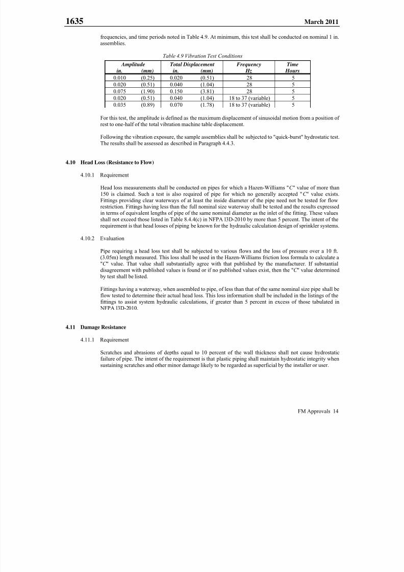
frequencies, and time periods noted in Table 4.9. At minimum, this test shall be conducted on nominal 1 in.
assemblies.
Table 4.9 Vibration Test Conditions
Amplitude Total Displacement Frequency Time
in. (mm) in. (mm) Hz Hours
0.010 (0.25) 0.020 (0.51) 28 5
0.020 (0.51) 0.040 (1.04) 28 50.075 (1.90) 0.150 (3.81) 28 5
0.020 (0.51) 0.040 (1.04) 18 to 37 (variable) 5
0.035 (0.89) 0.070 (1.78) 18 to 37 (variable) 5
For this test, the amplitude is defined as the maximum displacement of sinusoidal motion from a position of
rest to one-half of the total vibration machine table displacement.
Following the vibration exposure, the sample assemblies shall be subjected to "quick-burst" hydrostatic test.
The results shall be assessed as described in Paragraph 4.4.3.
4.10 Head Loss (Resistance to Flow)
4.10.1 Requirement
Head loss measurements shall be conducted on pipes for which a Hazen-Williams "C " value of more than
150 is claimed. Such a test is also required of pipe for which no generally accepted "C " value exists.
Fittings providing clear waterways of at least the inside diameter of the pipe need not be tested for flowrestriction. Fittings having less than the full nominal size waterway shall be tested and the results expressed
in terms of equivalent lengths of pipe of the same nominal diameter as the inlet of the fitting. These values
shall not exceed those listed in Table 8.4.4(c) in NFPA l3D-2010 by more than 5 percent. The intent of the
requirement is that head losses of piping be known for the hydraulic calculation design of sprinkler systems.
4.10.2 Evaluation
Pipe requiring a head loss test shall be subjected to various flows and the loss of pressure over a 10 ft.(3.05m) length measured. This loss shall be used in the Hazen-Williams friction loss formula to calculate a
"C " value. That value shall substantially agree with that published by the manufacturer. If substantial
disagreement with published values is found or if no published values exist, then the "C " value determined
by test shall be listed.
Fittings having a waterway, when assembled to pipe, of less than that of the same nominal size pipe shall be
flow tested to determine their actual head loss. This loss information shall be included in the listings of the
fittings to assist system hydraulic calculations, if greater than 5 percent in excess of those tabulated in NFPA l3D-2010.
4.11 Damage Resistance
4.11.1 Requirement
Scratches and abrasions of depths equal to 10 percent of the wall thickness shall not cause hydrostaticfailure of pipe. The intent of the requirement is that plastic piping shall maintain hydrostatic integrity when
sustaining scratches and other minor damage likely to be regarded as superficial by the installer or user.
7/25/2019 Fm Approvals 1635 Std 2011
http://slidepdf.com/reader/full/fm-approvals-1635-std-2011 19/55
1635 March 2011
FM Approvals 15
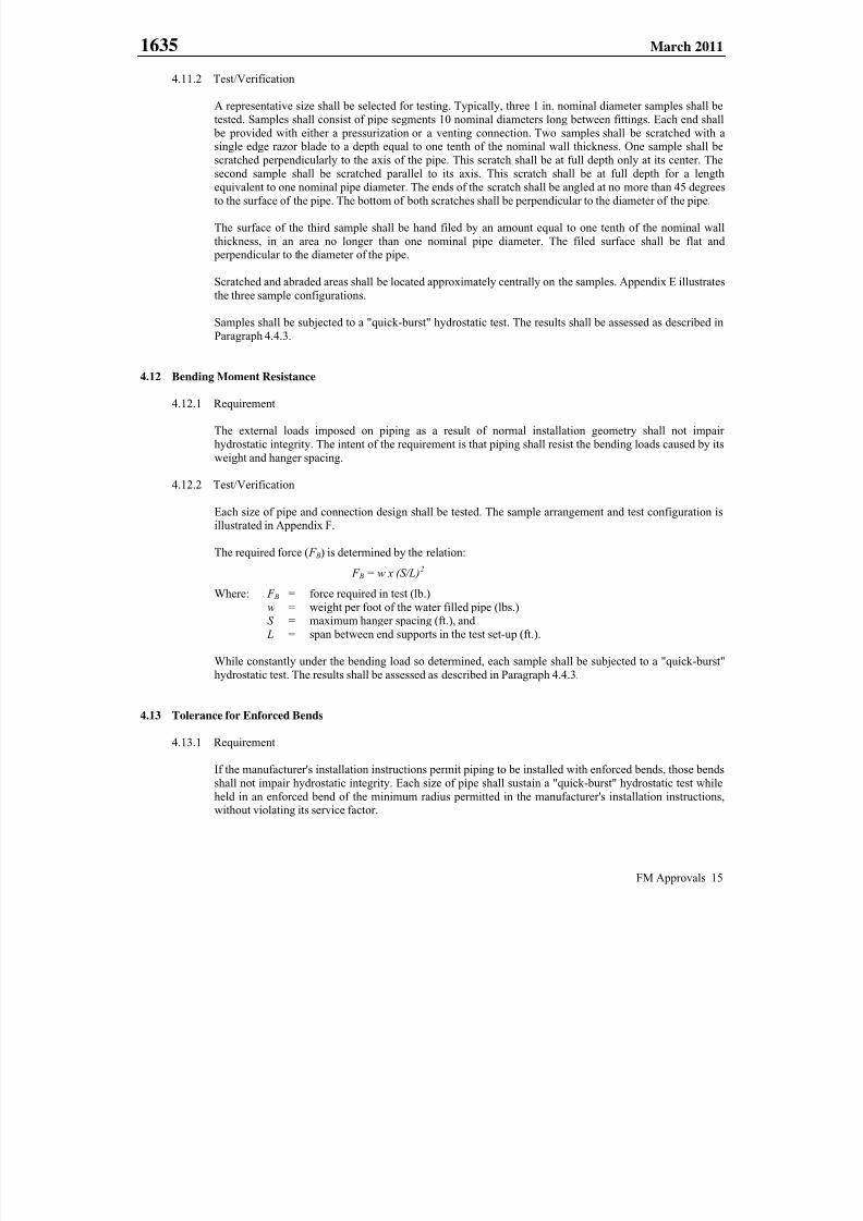
4.11.2 Test/Verification
A representative size shall be selected for testing. Typically, three 1 in. nominal diameter samples shall be
tested. Samples shall consist of pipe segments 10 nominal diameters long between fittings. Each end shall
be provided with either a pressurization or a venting connection. Two samples shall be scratched with asingle edge razor blade to a depth equal to one tenth of the nominal wall thickness. One sample shall be
scratched perpendicularly to the axis of the pipe. This scratch shall be at full depth only at its center. The
second sample shall be scratched parallel to its axis. This scratch shall be at full depth for a lengthequivalent to one nominal pipe diameter. The ends of the scratch shall be angled at no more than 45 degrees
to the surface of the pipe. The bottom of both scratches shall be perpendicular to the diameter of the pipe.
The surface of the third sample shall be hand filed by an amount equal to one tenth of the nominal wall
thickness, in an area no longer than one nominal pipe diameter. The filed surface shall be flat and perpendicular to the diameter of the pipe.
Scratched and abraded areas shall be located approximately centrally on the samples. Appendix E illustrates
the three sample configurations.
Samples shall be subjected to a "quick-burst" hydrostatic test. The results shall be assessed as described in
Paragraph 4.4.3.
4.12 Bending Moment Resistance
4.12.1 Requirement
The external loads imposed on piping as a result of normal installation geometry shall not impair
hydrostatic integrity. The intent of the requirement is that piping shall resist the bending loads caused by its
weight and hanger spacing.
4.12.2 Test/Verification
Each size of pipe and connection design shall be tested. The sample arrangement and test configuration isillustrated in Appendix F.
The required force ( F B) is determined by the relation:
F B = w x (S/L)2
Where: F B = force required in test (lb.)
w = weight per foot of the water filled pipe (lbs.)S = maximum hanger spacing (ft.), and
L = span between end supports in the test set-up (ft.).
While constantly under the bending load so determined, each sample shall be subjected to a "quick-burst"
hydrostatic test. The results shall be assessed as described in Paragraph 4.4.3.
4.13 Tolerance for Enforced Bends
4.13.1 Requirement
If the manufacturer's installation instructions permit piping to be installed with enforced bends, those bends
shall not impair hydrostatic integrity. Each size of pipe shall sustain a "quick-burst" hydrostatic test while
held in an enforced bend of the minimum radius permitted in the manufacturer's installation instructions,without violating its service factor.

7/25/2019 Fm Approvals 1635 Std 2011
http://slidepdf.com/reader/full/fm-approvals-1635-std-2011 20/55
1635 March 2011
FM Approvals 16
4.13.2 Test/Verification
Test samples shall be assembled with a pressurization or venting connection at each end. Samples shall be
of sufficient length to describe a 90 degree arc at the minimum bending radius specified plus an additional
20 nominal pipe diameters of length. A structure of nominal 2x4 construction lumber shall be assembled toforce the pipe into the bend and hold it in that position during test. Three points of restraint shall be
maintained. The 2x4's shall contact the pipe at the center, inside of the bend, and the outer outside ends of
the bend. Lateral restraint shall be provided to prevent the pipe from moving along the 2x4's. The points ofcontact shall be corners of the 2x4's, rather than their flat surfaces.
The samples shall be subjected to "quick-burst" hydrostatic tests. The results shall be assessed as described
in Paragraph 4.4.3.
4.14 Thermal Expansion and Contraction
4.14.1 Requirement
The maximum tensile force produced by a temperature decrease of 100F (56C) acting on a length of pipe
equal to the maximum hanger spacing shall be imposed on sample piping. No violation of the pressurerating factor of safety shall result. Plastic piping typically exhibits large thermal expansion coefficients. The
restraints imposed by installation hanging and fixing result in axial forces in piping when temperature
changes occur. The intent of this requirement is that such forces shall not impair the hydrostatic integrity ofthe system.
4.14.2 Test/Verification
Representative test samples shall be selected. Typically, a sample shall consist of two segments of pipe,
each three feet (1 m) long, joined in the center to a fitting, and provided with a pressurization or venting
connection at each end. A constant axial tension force ( F t ) shall be imposed on the sample throughout the
test. This force is calculated by the relation:
F t = π x (d x t - t 2 ) x E x a x ΔT
Where: F t = tensile force due to temperature,
d = pipe outside diameter,t = pipe wall thickness,
E = modulus of elasticity (units of Force per Area),a = thermal coefficient of expansion (units of length per unit length per thermal degree), and
ΔT = temperature change, 100F (56C).
While under its appropriately calculated F t , each sample shall be subjected to a "quick-burst" hydrostatic
test. The results shall be assessed as described in Paragraph 4.4.3.
4.15 Ultraviolet (UV) Resistance
4.15.1 Requirement
Plastic pipe shall not exhibit a decrease in hydrostatic integrity, below that accounted for by the safety
factor, as a result of exposure to a combined 96 hours of UV “B” and condensation. Piping, prior to
installation, may be stored outdoors. UV “B” radiation in sunlight causes degradation of plastics. The intent
of this requirement is that such degradation shall not impair the ability to join the pipe and/or fittings nor itssubsequent hydrostatic integrity.

7/25/2019 Fm Approvals 1635 Std 2011
http://slidepdf.com/reader/full/fm-approvals-1635-std-2011 21/55
1635 March 2011
FM Approvals 17
4.15.2 Test/Verification
A minimum of six pipe samples of a representative size shall be selected. Typically, samples of the nominal
1 in. size 1 ft. (0.3 m) long shall be used. Samples shall be rinsed in water and wiped dry with paper towels.
Samples shall then be installed in a fluorescent UV “B” condensation type weathering apparatus, asdescribed in ASTM G154-06. Ultraviolet "B" fluorescent lamps shall be used. (UV "B" radiation is the
most destructive component remaining in sunlight reaching the earth's surface). Exposure duration shall be
96 hours with a continuously repeated cycle of 8 hours of UV “B” and 4 hours of condensation. The cabinettemperature shall be 145F (63C) during the condensation portion.
After exposure the samples shall be allowed to cool to ambient temperature, dried, and then joined to end
fittings providing pressurization or venting connections and subjected to a "quick- burst" hydrostatic test.Test results shall be assessed as described in Paragraph 4.4.3.
4.16 Permanence of Markings
4.16.1 Requirement
Normal handling and weathering shall not render markings illegible. Markings shall be water and oilresistant.
4.16.2 Test/Verification
Representative samples of pipe and fittings shall be selected. Samples shall be subjected to water immersion
for 5 minutes per day for 10 days. After each sample is removed from the water each day, it shall be rubbedvigorously on the marked surface with paper towels. Marking shall not smear, bleed, or deposit residue on
the towels. After the conclusion of the 10 days of water exposure testing, the samples shall be covered with
petroleum-based grease and remain undisturbed for 24 hours. After that time has elapsed, the grease shall be
removed from the samples by wiping with paper towels. Vigorous rubbing of the marked surface shall not
result in smearing, bleeding, or other removal of markings. Molded or embossed markings need not besubjected to this test.
4.17 Service Factor
4.17.1 Requirement
Adverse conditions shall not reduce the pressure capacity of the piping by more than that accounted for by
the service factor. A maximum service factor of 0.5 shall be allowed on hydrostatic design for the pressure
rating of the pipe under all conditions of service.
4.17.2 Test/Verification
The result of the hydrostatic tests of Paragraph 5.2 shall be termed the "base-line quick-burst pressure":
(QBb) for a given size. The lowest result for a given size from the tests of Sections 4.4, 4.5., 4.8, 4.9, 4.11,4.12, 4.13, 4.14, or 4.15, whichever is the lowest, shall be termed the "impaired quick-burst pressure" (QBi).
The relation: F = (QBi - PS 15 ) ÷ (QBb - PS 15 )
where PS 15 is the surge pressure allowance for an instantaneous water velocity change of 15 ft/sec (4.6 m/s),
shall be used to calculate a service factor ( F ) for each size. The least of these calculated F 's shall be
identified. If that F is less than 0.5, then it shall be used to recalculate the hydrostatic design basis ( HDB)for both rating temperatures by the relation:
HDS = HDB x F
7/25/2019 Fm Approvals 1635 Std 2011
http://slidepdf.com/reader/full/fm-approvals-1635-std-2011 22/55
1635 March 2011
FM Approvals 18
and a corresponding new pressure rating for the pipe shall be calculated for both rating temperatures as
follows:
PR = (2 x HDS) ÷ (SDR - 1)
where PR is the pressure rating, and SDR is the dimension ratio of the pipe.
Approval shall be limited to a new PR, so derived. A product having a PR less than 175 psi (1205 kPa) can
not be FM Approved.
4.18 Chemical Compatibility Test for Environmental Stress Cracking between Plastic Piping Products and Steel
Sprinkler Pipe with Antimicrobial (AMC) and/or Antibacterial Coatings/Films
If one of the intended uses of the plastic pipe and fittings is in hybrid sprinkler systems using internally coated steel
pipe (i.e. plastic pipe connected to internally coated steel pipe), evaluation of plastic pipe and fittings under this
standard shall include chemical compatibility testing with all FM Approved manufacturer applied internally coated
steel pipe (i.e. internally coated by the manufacturer) in accordance with Appendix N.
4.18.1 Requirement
When exposed to a solution of deionized (DI) water and the extract from Antimicrobial (AMC) or
Antibacterial coated steel pipe, Type V tensile specimens of plastic pipe shall experience neither an averagereduction of more than 20 percent in Tensile Stress at Yield nor an average reduction of more than50 percent in Elongation at Break when compared to unexposed control specimens. There shall be no cracks
or crazes visually observable on the tensile surface and edges of exposed specimens for all specified
exposure periods. Results of this testing will be reported as PASS or FAIL in the applicable test
documentation. When testing is required for compatibility with plastic fittings only, special considerations
will be given to the shape of the test samples and will be determined by FM Approvals at the time of projectinitiation.
4.18.2 Test/Verification
Testing shall be performed in accordance with Appendix N.
4.19 Additional Tests
At the discretion of FM Approvals additional tests may be required, depending on design features, results of any
tests, material application, or to verify the integrity and reliability of the pipe and/or fittings.
Unexplained failures shall not be permitted. A re-test shall only be acceptable at the discretion of FM Approvals with
adequate technical justification of the conditions and reasons for failure.
7/25/2019 Fm Approvals 1635 Std 2011
http://slidepdf.com/reader/full/fm-approvals-1635-std-2011 23/55
1635 March 2011
FM Approvals 19
5. PERFORMANCE REQUIREMENTS - EXPOSED
In addition to the requirements outlined in Section 4 of this standard, plastic piping that is to be FM Approved for
exposed/unexposed service must also meet the performance requirements of the nine fire tests, as defined in Sections
5.1, 5.2, 5.3, 5.4, 5.5, 5.6, 5.7, 5.8, and 5.9, of this standard.
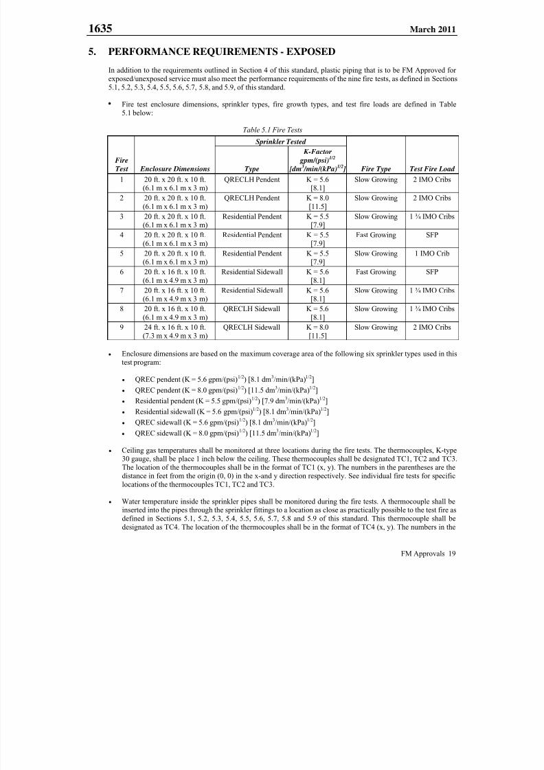
Fire test enclosure dimensions, sprinkler types, fire growth types, and test fire loads are defined in Table
5.1 below:
Table 5.1 Fire Tests
Fire
Test Enclosure Dimensions
Sprinkler Tested
Fire Type Test Fire Load Type
K-Factor
gpm/(psi)1/2
[dm 3 /min/(kPa)1/2 ]
1 20 ft. x 20 ft. x 10 ft.(6.1 m x 6.1 m x 3 m)
QRECLH Pendent K = 5.6[8.1]
Slow Growing 2 IMO Cribs
2 20 ft. x 20 ft. x 10 ft.
(6.1 m x 6.1 m x 3 m)
QRECLH Pendent K = 8.0
[11.5]
Slow Growing 2 IMO Cribs
3 20 ft. x 20 ft. x 10 ft.
(6.1 m x 6.1 m x 3 m)
Residential Pendent K = 5.5
[7.9]
Slow Growing 1 ¾ IMO Cribs
4 20 ft. x 20 ft. x 10 ft.
(6.1 m x 6.1 m x 3 m)
Residential Pendent K = 5.5
[7.9]
Fast Growing SFP
5 20 ft. x 20 ft. x 10 ft.(6.1 m x 6.1 m x 3 m)
Residential Pendent K = 5.5[7.9]
Slow Growing 1 IMO Crib
6 20 ft. x 16 ft. x 10 ft.
(6.1 m x 4.9 m x 3 m)
Residential Sidewall K = 5.6
[8.1]
Fast Growing SFP
7 20 ft. x 16 ft. x 10 ft.(6.1 m x 4.9 m x 3 m)
Residential Sidewall K = 5.6[8.1]
Slow Growing 1 ¾ IMO Cribs
8 20 ft. x 16 ft. x 10 ft.
(6.1 m x 4.9 m x 3 m)
QRECLH Sidewall K = 5.6
[8.1]
Slow Growing 1 ¾ IMO Cribs
9 24 ft. x 16 ft. x 10 ft.
(7.3 m x 4.9 m x 3 m)
QRECLH Sidewall K = 8.0
[11.5]
Slow Growing 2 IMO Cribs
Enclosure dimensions are based on the maximum coverage area of the following six sprinkler types used in this
test program:
QREC pendent (K = 5.6 gpm/(psi)1/2) [8.1 dm3/min/(kPa)1/2]
QREC pendent (K = 8.0 gpm/(psi)1/2) [11.5 dm3/min/(kPa)1/2]
Residential pendent (K = 5.5 gpm/(psi)1/2) [7.9 dm3/min/(kPa)1/2]
Residential sidewall (K = 5.6 gpm/(psi)1/2) [8.1 dm3/min/(kPa)1/2]
QREC sidewall (K = 5.6 gpm/(psi)1/2) [8.1 dm3/min/(kPa)1/2]
QREC sidewall (K = 8.0 gpm/(psi)1/2) [11.5 dm3/min/(kPa)1/2]
Ceiling gas temperatures shall be monitored at three locations during the fire tests. The thermocouples, K-type30 gauge, shall be place 1 inch below the ceiling. These thermocouples shall be designated TC1, TC2 and TC3.
The location of the thermocouples shall be in the format of TC1 (x, y). The numbers in the parentheses are the
distance in feet from the origin (0, 0) in the x-and y direction respectively. See individual fire tests for specific
locations of the thermocouples TC1, TC2 and TC3.
Water temperature inside the sprinkler pipes shall be monitored during the fire tests. A thermocouple shall beinserted into the pipes through the sprinkler fittings to a location as close as practically possible to the test fire as
defined in Sections 5.1, 5.2, 5.3, 5.4, 5.5, 5.6, 5.7, 5.8 and 5.9 of this standard. This thermocouple shall be
designated as TC4. The location of the thermocouples shall be in the format of TC4 (x, y). The numbers in the

7/25/2019 Fm Approvals 1635 Std 2011
http://slidepdf.com/reader/full/fm-approvals-1635-std-2011 24/55
1635 March 2011
FM Approvals 20
parentheses are the distance in feet from the origin (0, 0) in the x-and y direction respectively. See individual
fire tests for specific locations of thermocouple TC4.
Sprinkler actuation shall be detected by a thermocouple installed in close proximity to the sprinkler deflector.
This thermocouple shall be designated as TC5.
In order to measure and control water flow rates discharged from the sprinkler in each test, the static water
pressure applied to the sprinkler shall be measured by installing a pressure transducer at the end of the sprinkler pipe.
Fire tests requiring a slowly growing fire type shall use test cribs in accordance with the International Maritime
Organization (IMO) as a fuel source. An IMO crib consists of six 18 in. (455 mm) lengths of trade size nominal
2 in. x 2 in. (50 mm x 50 mm) kiln-dried spruce of fir lumber per layer, having a moisture content between9 percent and 13 percent. The members are placed in four alternate layers at right angles to one another. The
members are to be evenly spaced forming an 18 in. x 18 in. (455 mm x 455 mm) square structure, as shown in
Appendix G. The heat release rate of each IMO crib is approximately 300 kW. The IMO cribs are placed above
the ignition source as shown in Appendix H.
Fire tests requiring a fast growing fire shall use an FM Global Research simulated furniture package (SFP), as
shown in Appendix I, as a fuel source. The materials required for a SFP are: (1) two 4 ft. wide x 10 ft. high x
¼ in. thick (1.2 m x 3.0 m x 6.4 mm) Douglas Fir plywood sheets, (2) simulated furniture that shall be made up
of foam cushions attached to a plywood backing and supported by a steel frame. The cushions shall consist oftwo pieces of uncovered pure polypropylene oxide polyol, polyether foam having a density of 1.70 lb/ft 3 to
1.90 lb/ft3 (27.2 kg/m3 to 30.4 kg/m3) and measuring 34 in. wide x 30 in. high x 3 in. thick (860 mm wide x
760 mm high x 76 mm thick). Five samples of the polyether foam shall be tested for burning characteristics andthe average properties shall conform to the requirements specified in Table 5.2. Each foam cushion shall be
fixed to a 35 in. x 31 in. (890 mm x 790 mm), nominal 1/2 in. (12.7 mm) thick plywood backing using an
aerosol urethane foam adhesive. Location of the foam on the plywood shall result in a 0.5 in. (13 mm) gap
between the sides of the cushion and the sides of the backing, and a 1 in. (25 mm) gap between the bottom of thecushion and the bottom of the backing as illustrated in Appendix I. The foam cushion and plywood backing
assembly shall be conditioned at 70°F ± 5°F (21°C ± 2.8°C) and 50 percent ± 10 percent relative humidity for at
least 24 hours prior to testing. Before each test, the foam and plywood backing assembly shall be placed in a
steel support frame that holds the assembly in the vertical position. (3) the previously described IMO crib placedover a 12 in. x 12 in. x 4 in. (305 mm x 305 mm x 102 mm) pan containing 0.53 gal (200 ml) of water and
0.53 gal (200 ml) of heptane, and (4) ceiling tiles covering a 4 ft. x 10 ft. (1.2 m x 3 m) area with a specificationof having a Flame Spread Index of 25 in accordance with criteria defined in ASTM E84-09c.
Table 5.2 Required Burning Characteristics of Polyether Foam
Property Test Method Requirement
Chemical Heat of
Combustion
Test method for Heat and Visible Smoke Release Rates for
Materials and products Using Oxygen ConsumptionCalorimeter, ASTM E1354-97 at 30 kW/m2 heat flux
22 kJ/g ± 3 kJ/g
Peak Heat Release
Rate (HRR)
Test method for Heat and Visible Smoke Release Rates for
Materials and products Using Oxygen Consumption
Calorimeter, ASTM E1354-97 at 30 kW/m2 heat flux
230 kW/m2 ± 50 kW/m2
The water supply shall be at the end of the pipe closest to the test fire.
Pendent sprinklers shall be installed such that the distance from the ceiling to the sprinkler deflector is 6 in.
(150 mm).
Sidewall sprinklers shall be installed such that the distance from the ceiling to the sprinkler deflector is 6 in.
(150 mm).

7/25/2019 Fm Approvals 1635 Std 2011
http://slidepdf.com/reader/full/fm-approvals-1635-std-2011 25/55
1635 March 2011
FM Approvals 21
5.1 Fire Test 1
5.1.1 Requirement
A K = 5.6 gpm/(psi)1/2 [8.1 dm3/min/(kPa)1/2] quick response extended coverage light hazard (QRECLH)
pendent sprinkler, with a nominal temperature rating of 155F (68C) and providing 0.1 gal/min/ft2
(4.1 mm/min) discharge density, installed in CPVC pipe in the center of a 20 ft. x 20 ft. x 10 ft. (6.1 m x
6.1 m x 3 m) test enclosure, shall be able to control a slowly growing test fire without thermal deformationof the CPVC pipe or fittings. Following suppression of the fire, the water pressure in the sprinkler pipe shall
be increased to 175 psi (1205 kPa) for 10 minutes. No damage, distortion or thermal deformation to the
CPVC pipe or fittings that would impair the operation of the sprinkler or sprinkler system is permitted. The
sprinkler shall then be plugged and the sprinkler piping system shall be hydrostatically tested to 175 psi(1205 kPa) for 2 minutes. Through visual inspection, no water leakage from the sprinkler piping system is
permitted.
5.1.2 Test/Verification
A K = 5.6 gpm/(psi)1/2 [8.1 dm3/min/(kPa)1/2] QRECLH pendent sprinkler with nominal a temperature
rating of 155F (68C) shall be installed at the center of a 20 ft. x 20 ft. x 10 ft. (6.1 m x 6.1 m x 3 m) test
enclosure as shown in Figure 5.1. The CPVC piping arrangement shall consist of SDR 13.5 CPVC pipe and
schedule 40 or 80 fittings and shall be nominal 1 inch size. Prior to testing, the integrity of the piping
system shall be verified by subjecting the piping system to a hydrostatic pressure of 175 psi (1205 kPa) fora period of 5 minutes. No leakage is permitted.
Temperature of the water inside the sprinkler pipe shall be monitored by thermocouple TC4 embedded inthe pipe directly above the center of the test fire located at x, y coordinates (1, 10) as shown in Figure 5.1.
Ceiling gas temperatures shall be monitored at 3 locations during the fire tests. The x, y coordinates of the
three thermocouple measuring points shall be as follows: TC1 (1.0, 8.5); TC2 (1.0, 9.5); and TC3(1.0, 10.5), as shown in Figure 5.1.
Two IMO cribs shall be placed 2 in. (50 mm) above a 6 in. (152 mm) diameter heptane filled ignition
source. The IMO cribs shall be located below the end section of the sprinkler pipe as shown in Figure 5.1.
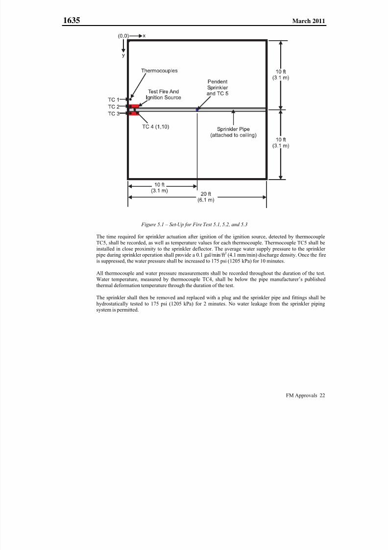
7/25/2019 Fm Approvals 1635 Std 2011
http://slidepdf.com/reader/full/fm-approvals-1635-std-2011 26/55
1635 March 2011
FM Approvals 22
Figure 5.1 – Set-Up for Fire Test 5.1, 5.2, and 5.3
The time required for sprinkler actuation after ignition of the ignition source, detected by thermocouple
TC5, shall be recorded, as well as temperature values for each thermocouple. Thermocouple TC5 shall beinstalled in close proximity to the sprinkler deflector. The average water supply pressure to the sprinkler
pipe during sprinkler operation shall provide a 0.1 gal/min/ft2 (4.1 mm/min) discharge density. Once the fire
is suppressed, the water pressure shall be increased to 175 psi (1205 kPa) for 10 minutes.
All thermocouple and water pressure measurements shall be recorded throughout the duration of the test.Water temperature, measured by thermocouple TC4, shall be below the pipe manufacturer’s published
thermal deformation temperature through the duration of the test.
The sprinkler shall then be removed and replaced with a plug and the sprinkler pipe and fittings shall be
hydrostatically tested to 175 psi (1205 kPa) for 2 minutes. No water leakage from the sprinkler pipingsystem is permitted.

7/25/2019 Fm Approvals 1635 Std 2011
http://slidepdf.com/reader/full/fm-approvals-1635-std-2011 27/55
1635 March 2011
FM Approvals 23
5.2 Fire Test 2
5.2.1 Requirement
A K = 8.0 gpm/(psi)1/2 [11.5 dm3/min/(kPa)1/2] QRECLH pendent sprinkler, with nominal temperature
rating of 155F (68C) and providing 0.1 gal/min/ft2 (4.1 mm/min) discharge density, installed in CPVC
pipe in the center of a 20 ft. x 20 ft. x 10 ft. (6.1 m x 6.1 m x 3 m) test enclosure, shall be able to control a
slowly growing test fire without thermal deformation of the CPVC pipe or fittings. Following suppressionof the fire, the water pressure in the sprinkler pipe shall be increased to 175 psi (1205 kPa) for 10 minutes.
No damage, distortion or thermal deformation to the CPVC pipe or fittings that would impair the operation
of the sprinkler or sprinkler system is permitted. The sprinkler shall then be plugged and the sprinkler
piping system shall be hydrostatically tested to 175 psi (1205 kPa) for 2 minutes. Through visual inspection,no water leakage from the sprinkler piping system is permitted.
5.2.2 Test/Verification
A K = 8.0 gpm/(psi)1/2 [11.5 dm3/min/(kPa)1/2] QRECLH pendent sprinkler with nominal temperature rating
of 155F (68C) shall be installed in the CPVC pipe in the center of a 20 ft. x 20 ft. x 10 ft. (6.1 m x 6.1 m x3 m) test enclosure as shown in Figure 5.1. The CPVC piping arrangement shall consist of SDR 13.5 CPVC
pipe and schedule 40 or 80 fittings and shall nominal 1 inch size. Prior to testing, the integrity of the piping
system shall be verified by subjecting the piping system to a hydrostatic pressure of 175 psi (1205 kPa) for
a period of 5 minutes. No leakage is permitted.
Temperature of the water inside the sprinkler pipe shall be monitored by thermocouple TC4 embedded in
the pipe directly above the center of the test fire located at x, y coordinates (1, 10) as shown in Figure 5.1.
Ceiling gas temperatures shall be monitored at 3 locations during the fire tests. The x, y coordinates of the
three thermocouple measuring points shall be as follows: TC1 (1.0, 8.5); TC2 (1.0, 9.5); and TC3
(1.0, 10.5), as shown in Figure 5.1.
Two IMO cribs shall be placed 2 in. (50 mm) above a 6 in. (152 mm) diameter heptane filled ignition
source. The IMO cribs shall be located below the end section of the sprinkler pipe as shown in Figure 5.1.
The time required for sprinkler actuation after ignition of the ignition source, detected by thermocouple
TC5, shall be recorded, as well as temperature values for each thermocouple. Thermocouple TC5 shall beinstalled in close proximity to the sprinkler deflector. The average water supply pressure to the sprinkler
pipe during sprinkler operation shall provide a 0.1 gal/min/ft2 (4.1 mm/min) discharge density. Once the fire
is suppressed, the water pressure shall be increased to 175 psi (1205 kPa) for 10 minutes.
All thermocouple and water pressure measurements shall be recorded throughout the duration of the test.
Water temperature, measured by thermocouple TC4, shall be below the pipe manufacturer’s publishedthermal deformation temperature through the duration of the test.
The sprinkler shall then be removed and replaced with a plug and the sprinkler pipe and fittings shall be
hydrostatically tested to 175 psi (1205 kPa) for 2 minutes. No water leakage from the sprinkler pipingsystem is permitted.
7/25/2019 Fm Approvals 1635 Std 2011
http://slidepdf.com/reader/full/fm-approvals-1635-std-2011 28/55
1635 March 2011
FM Approvals 24
5.3 Fire Test 3
5.3.1 Requirement
A K = 5.5 gpm/(psi)1/2 [7.9 dm3/min/(kPa)1/2] pendent residential sprinkler, with a nominal temperature
rating of 155F (68C) and providing 0.1 gal/min/ft2 (4.1 mm/min) discharge density, installed in CPVC
pipe in the center of a 20 ft. x 20 ft. x 10 ft. (6.1 m x 6.1 m x 3 m) test enclosure, shall be able to control a
slowly growing test fire without thermal deformation of the CPVC pipe or fittings. Following suppressionof the fire, the water pressure in the sprinkler pipe shall be increased to 175 psi (1205 kPa) for 10 minutes.
No damage, distortion or thermal deformation to the CPVC pipe or fittings that would impair the operation
of the sprinkler or sprinkler system is permitted. The sprinkler shall then be plugged and the sprinkler
piping system shall be hydrostatically tested to 175 psi (1205 kPa) for 2 minutes. Through visual inspection,no water leakage from the sprinkler piping system is permitted.
5.3.2 Test/Verification
A K = 5.5 gpm/(psi)1/2 [7.9 dm3/min/(kPa)1/2] pendent residential sprinkler with a nominal temperature
rating of 155F (68C) shall be installed in the CPVC pipe in the center of a 20 ft. x 20 ft. x 10 ft. (6.1 m x6.1 m x 3 m) test enclosure as shown in Figure 5.1. The CPVC piping arrangement shall consist of SDR
13.5 CPVC pipe and schedule 40 or 80 fittings and shall nominal 1 inch size. Prior to testing, the integrity
of the piping system shall be verified by subjecting the piping system to a hydrostatic pressure of 175 psi
(1205 kPa) for a period of 5 minutes. No leakage is permitted.
Temperature of the water inside the sprinkler pipe shall be monitored by thermocouple TC4 embedded in
the pipe directly above the center of the test fire located at x, y coordinates (1, 10) as shown in Figure 5.1.
Ceiling gas temperatures shall be monitored at 3 locations during the fire tests. The x, y coordinates of the
three thermocouple measuring points shall be as follows: TC1 (1.0, 8.5); TC2 (1.0, 9.5); and TC3
(1.0, 10.5), as shown in Figure 5.1.
One and 3/4 IMO cribs shall be placed 2 in. (50 mm) above a 6 in. (152 mm) diameter heptane filled
ignition source. The IMO cribs shall be located below the end section of the sprinkler pipe as shown in
Figure 5.2.
The time required for sprinkler actuation after ignition of the ignition source, detected by thermocoupleTC5, shall be recorded, as well as temperature values for each thermocouple. Thermocouple TC5 shall beinstalled in close proximity to the sprinkler deflector. The average water supply pressure to the sprinkler
pipe during sprinkler operation shall provide a 0.1 gal/min/ft2 (4.1 mm/min) discharge density. Once the fire
is suppressed, the water pressure shall be increased to 175 psi (1205 kPa) for 10 minutes.
All thermocouple and water pressure measurements shall be recorded throughout the duration of the test.Water temperature, measured by thermocouple TC4, shall be below the pipe manufacturer’s published
thermal deformation temperature through the duration of the test.
The sprinkler shall then be removed and replaced with a plug and the sprinkler pipe and fittings shall behydrostatically tested to 175 psi (1205 kPa) for 2 minutes. No water leakage from the sprinkler piping
system is permitted.
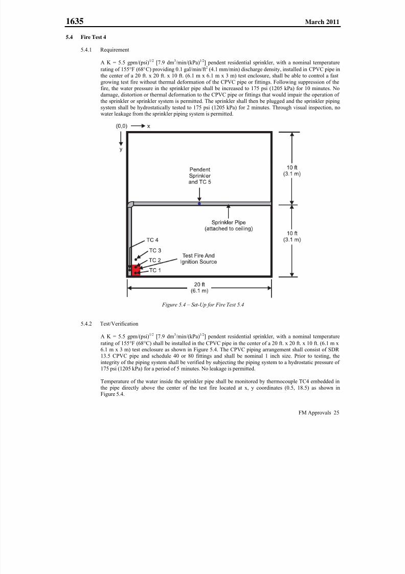
7/25/2019 Fm Approvals 1635 Std 2011
http://slidepdf.com/reader/full/fm-approvals-1635-std-2011 29/55
1635 March 2011
FM Approvals 25
5.4 Fire Test 4
5.4.1 Requirement
A K = 5.5 gpm/(psi)1/2 [7.9 dm3/min/(kPa)1/2] pendent residential sprinkler, with a nominal temperature
rating of 155F (68C) providing 0.1 gal/min/ft2 (4.1 mm/min) discharge density, installed in CPVC pipe in
the center of a 20 ft. x 20 ft. x 10 ft. (6.1 m x 6.1 m x 3 m) test enclosure, shall be able to control a fast
growing test fire without thermal deformation of the CPVC pipe or fittings. Following suppression of thefire, the water pressure in the sprinkler pipe shall be increased to 175 psi (1205 kPa) for 10 minutes. No
damage, distortion or thermal deformation to the CPVC pipe or fittings that would impair the operation of
the sprinkler or sprinkler system is permitted. The sprinkler shall then be plugged and the sprinkler piping
system shall be hydrostatically tested to 175 psi (1205 kPa) for 2 minutes. Through visual inspection, nowater leakage from the sprinkler piping system is permitted.
Figure 5.4 – Set-Up for Fire Test 5.4
5.4.2 Test/Verification
A K = 5.5 gpm/(psi)1/2
[7.9 dm3
/min/(kPa)1/2
] pendent residential sprinkler, with a nominal temperaturerating of 155F (68C) shall be installed in the CPVC pipe in the center of a 20 ft. x 20 ft. x 10 ft. (6.1 m x6.1 m x 3 m) test enclosure as shown in Figure 5.4. The CPVC piping arrangement shall consist of SDR
13.5 CPVC pipe and schedule 40 or 80 fittings and shall be nominal 1 inch size. Prior to testing, the
integrity of the piping system shall be verified by subjecting the piping system to a hydrostatic pressure of175 psi (1205 kPa) for a period of 5 minutes. No leakage is permitted.
Temperature of the water inside the sprinkler pipe shall be monitored by thermocouple TC4 embedded in
the pipe directly above the center of the test fire located at x, y coordinates (0.5, 18.5) as shown inFigure 5.4.
7/25/2019 Fm Approvals 1635 Std 2011
http://slidepdf.com/reader/full/fm-approvals-1635-std-2011 30/55
1635 March 2011
FM Approvals 26
Ceiling gas temperatures shall be monitored at 3 locations during the fire tests. The x, y coordinates of thethree thermocouple measuring points shall be as follows: TC1 (1.0, 19.5); TC2 (1.0, 18.5); and TC3
(1.0, 17.5), as shown in Figure 5.4.
A simulated furniture package, as described in Section 5 and shown in Appendix I, shall be used as the test
fire load and located as shown in Figure 5.4. In addition to the 12 in. x 12 in. (305 mm x 305 mm) pan
containing 0.53 gal (200 ml) of water and 0.53 gal (200 ml) of heptane placed beneath the previouslydescribed IMO crib, two 6 in. long by ¼ in. diameter cotton wicks soaked with 0.27 gal (100 mL) of
heptane, shall be used as the ignition source. The heptane in the pan and the wicks shall be ignitedsimultaneously.
The time required for sprinkler actuation after ignition of the ignition source, detected by thermocoupleTC5, shall be recorded, as well as temperature values for each thermocouple. Thermocouple TC5 shall be
installed in close proximity to the sprinkler deflector. The average water supply pressure to the sprinkler
pipe during sprinkler operation shall provide a 0.1 gal/min/ft2 (4.1 mm/min) discharge density. Once the fire
is suppressed, the water pressure shall be increased to 175 psi (1205 kPa) for 10 minutes.
All thermocouple and water pressure measurements shall be recorded throughout the duration of the test.
Water temperature, measured by thermocouple TC4, shall be below the pipe manufacturer’s published
thermal deformation temperature through the duration of the test.
The sprinkler shall then be removed and replaced with a plug and the sprinkler pipe and fittings shall be
hydrostatically tested to 175 psi (1205 kPa) for 2 minutes. No water leakage from the sprinkler piping
system is permitted.
5.5 Fire Test 5
5.5.1 Requirement
A K = 5.5 gpm/(psi)1/2 [7.9 dm3/min/(kPa)1/2] pendent residential sprinkler, with a nominal temperature
rating of 155F (68C) and providing 0.1 gal/min/ft2 (4.1 mm/min) discharge density, installed in a 1 ft.
section of sprinkler pipe at the top of a CPVC pipe riser, shall be able to protect the exposed CPVC riser
pipe from long term fire exposure from a slowly growing test fire without thermal deformation of the CPVC pipe riser. The sprinkler is not meant to provide fire protection of the room where the riser is located.
Following control of the fire, the water pressure in the CPVC riser piping system shall be increased to
175 psi (1205 kPa) for 10 minutes. No damage, distortion or thermal deformation to the CPVC pipe orfittings that would impair the operation of the sprinkler or sprinkler system is permitted. The sprinkler shall
then be plugged and the CPVC riser piping system shall be hydrostatically tested to 175 psi (1205 kPa) for
2 minutes. Through visual inspection, no water leakage from the sprinkler piping system is permitted.
5.5.2 Test/Verification
A section of CPVC pipe shall be positioned vertically in the corner of a 20 ft. x 20 ft. x 10 ft. (6.1 m x 6.1 m
x 3 m) test enclosure as shown in Figure 5.5. The distance from each wall to the outside of the CPVC pipeshall not exceed 1.5 in. An additional section of CPVC pipe, not greater than 1 ft. in length, shall be
installed to the ceiling at the top of the CPVC riser at a 45 angle from each wall of the test enclosure. AK = 5.5 gpm/(psi)1/2 [7.9 dm3/min/(kPa)1/2] pendent residential sprinkler, with a nominal temperature rating
of 155F (68C) shall be installed at the end of the 1 ft. section of sprinkler pipe. The entire CPVC pipingarrangement described above shall consist of SDR 13.5 CPVC pipe and schedule 40 or 80 fittings and shall
be nominal 1 inch size. Prior to testing, the integrity of the piping system shall be verified by subjecting the
piping system to a hydrostatic pressure of 175 psi (1205 kPa) for a period of 5 minutes. No leakage is
permitted.
Temperature of the water inside the sprinkler pipe shall be monitored by thermocouple TC4 embedded in
the riser at a distance 2 ft. above the enclosure floor.
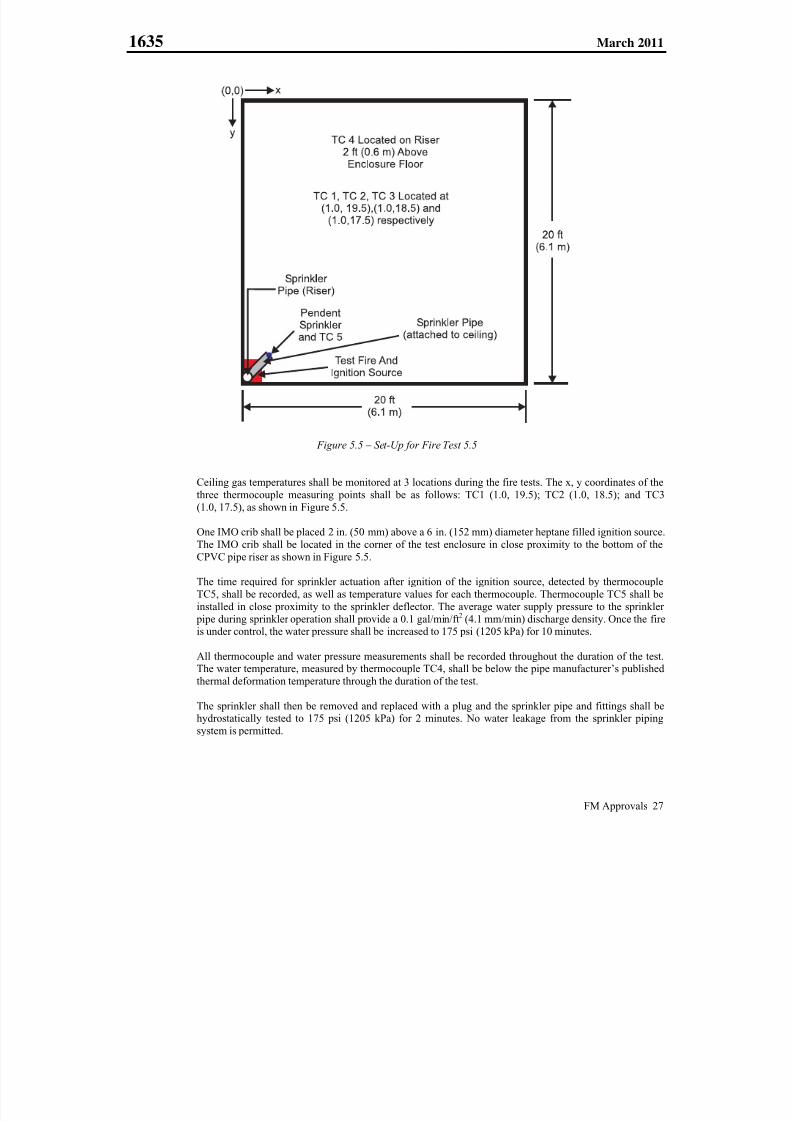
7/25/2019 Fm Approvals 1635 Std 2011
http://slidepdf.com/reader/full/fm-approvals-1635-std-2011 31/55
1635 March 2011
FM Approvals 27
Figure 5.5 – Set-Up for Fire Test 5.5
Ceiling gas temperatures shall be monitored at 3 locations during the fire tests. The x, y coordinates of the
three thermocouple measuring points shall be as follows: TC1 (1.0, 19.5); TC2 (1.0, 18.5); and TC3(1.0, 17.5), as shown in Figure 5.5.
One IMO crib shall be placed 2 in. (50 mm) above a 6 in. (152 mm) diameter heptane filled ignition source.
The IMO crib shall be located in the corner of the test enclosure in close proximity to the bottom of the
CPVC pipe riser as shown in Figure 5.5.
The time required for sprinkler actuation after ignition of the ignition source, detected by thermocouple
TC5, shall be recorded, as well as temperature values for each thermocouple. Thermocouple TC5 shall be
installed in close proximity to the sprinkler deflector. The average water supply pressure to the sprinkler
pipe during sprinkler operation shall provide a 0.1 gal/min/ft2 (4.1 mm/min) discharge density. Once the fireis under control, the water pressure shall be increased to 175 psi (1205 kPa) for 10 minutes.
All thermocouple and water pressure measurements shall be recorded throughout the duration of the test.The water temperature, measured by thermocouple TC4, shall be below the pipe manufacturer’s published
thermal deformation temperature through the duration of the test.
The sprinkler shall then be removed and replaced with a plug and the sprinkler pipe and fittings shall behydrostatically tested to 175 psi (1205 kPa) for 2 minutes. No water leakage from the sprinkler piping
system is permitted.
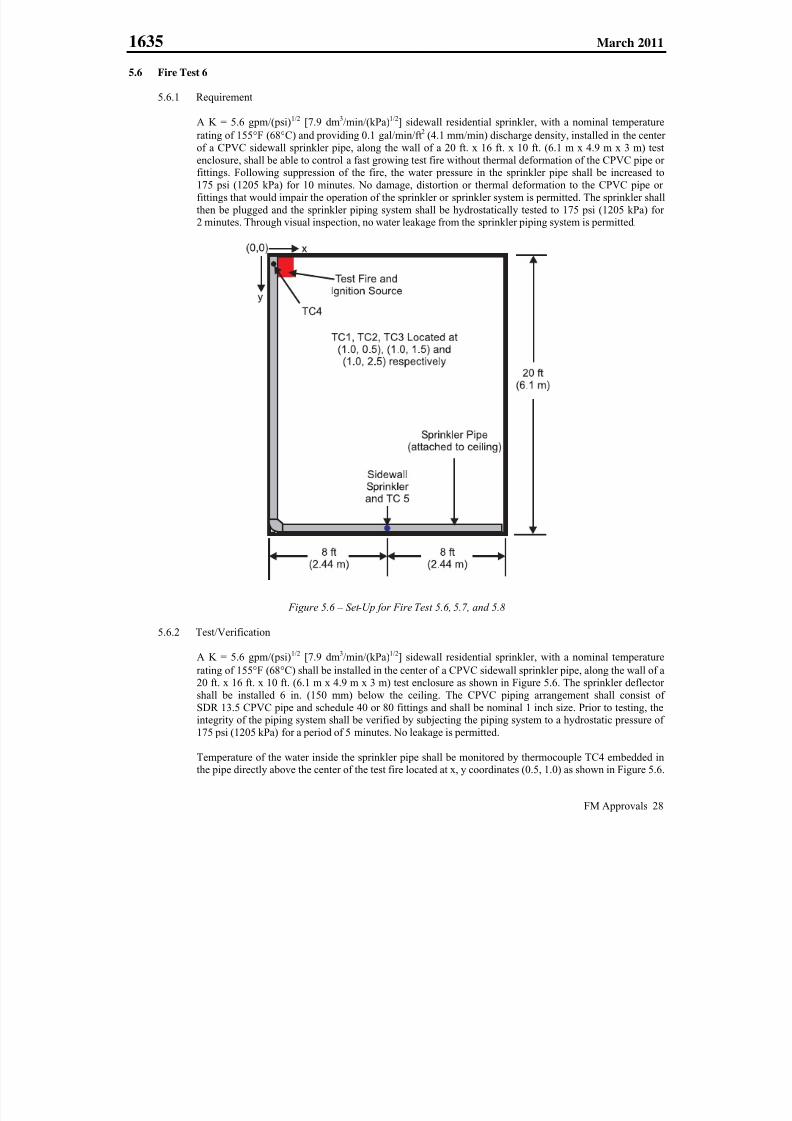
7/25/2019 Fm Approvals 1635 Std 2011
http://slidepdf.com/reader/full/fm-approvals-1635-std-2011 32/55
1635 March 2011
FM Approvals 28
5.6 Fire Test 6
5.6.1 Requirement
A K = 5.6 gpm/(psi)1/2 [7.9 dm3/min/(kPa)1/2] sidewall residential sprinkler, with a nominal temperature
rating of 155F (68C) and providing 0.1 gal/min/ft2 (4.1 mm/min) discharge density, installed in the center
of a CPVC sidewall sprinkler pipe, along the wall of a 20 ft. x 16 ft. x 10 ft. (6.1 m x 4.9 m x 3 m) test
enclosure, shall be able to control a fast growing test fire without thermal deformation of the CPVC pipe orfittings. Following suppression of the fire, the water pressure in the sprinkler pipe shall be increased to
175 psi (1205 kPa) for 10 minutes. No damage, distortion or thermal deformation to the CPVC pipe or
fittings that would impair the operation of the sprinkler or sprinkler system is permitted. The sprinkler shall
then be plugged and the sprinkler piping system shall be hydrostatically tested to 175 psi (1205 kPa) for2 minutes. Through visual inspection, no water leakage from the sprinkler piping system is permitted.
Figure 5.6 – Set-Up for Fire Test 5.6, 5.7, and 5.8
5.6.2 Test/Verification
A K = 5.6 gpm/(psi)1/2
[7.9 dm3
/min/(kPa)1/2
] sidewall residential sprinkler, with a nominal temperaturerating of 155F (68C) shall be installed in the center of a CPVC sidewall sprinkler pipe, along the wall of a20 ft. x 16 ft. x 10 ft. (6.1 m x 4.9 m x 3 m) test enclosure as shown in Figure 5.6. The sprinkler deflector
shall be installed 6 in. (150 mm) below the ceiling. The CPVC piping arrangement shall consist of
SDR 13.5 CPVC pipe and schedule 40 or 80 fittings and shall be nominal 1 inch size. Prior to testing, theintegrity of the piping system shall be verified by subjecting the piping system to a hydrostatic pressure of
175 psi (1205 kPa) for a period of 5 minutes. No leakage is permitted.
Temperature of the water inside the sprinkler pipe shall be monitored by thermocouple TC4 embedded inthe pipe directly above the center of the test fire located at x, y coordinates (0.5, 1.0) as shown in Figure 5.6.
7/25/2019 Fm Approvals 1635 Std 2011
http://slidepdf.com/reader/full/fm-approvals-1635-std-2011 33/55
1635 March 2011
FM Approvals 29
Ceiling gas temperatures shall be monitored at 3 locations during the fire tests. The x, y coordinates of thethree thermocouple measuring points shall be as follows: TC1 (1.0, 0.5); TC2 (1.0, 1.5); and TC3 (1.0, 2.5),
as shown in Figure 5.6.
A simulated furniture package, as described in Section 5 and shown in Appendix I, shall be used as the test
fire load and located as shown in Figure 5.6. In addition to the 12 in. x 12 in. (305 mm x 305 mm) pan
containing 0.53 gal (200 ml) of water and 0.53 gal (200 ml) of heptane placed beneath the previouslydescribed IMO crib, two 6 in. long by ¼ in. diameter cotton wicks soaked with 0.27 gal (100 mL) of
heptane, shall be used as the ignition source. The heptane in the pan and the wicks shall be ignitedsimultaneously.
The time required for sprinkler actuation after ignition of the ignition source, detected by thermocoupleTC5, shall be recorded, as well as temperature values for each thermocouple. Thermocouple TC5 shall be
installed in close proximity to the sprinkler deflector. The average water supply pressure to the sprinkler
pipe during sprinkler operation shall provide a 0.1 gal/min/ft2 (4.1 mm/min) discharge density. Once the fire
is suppressed, the water pressure shall be increased to 175 psi (1205 kPa) for 10 minutes.
All thermocouple and water pressure measurements shall be recorded throughout the duration of the test.
Water temperature, measured by thermocouple TC4, shall be below the pipe manufacturer’s published
thermal deformation temperature through the duration of the test.
The sprinkler shall then be removed and replaced with a plug and the sprinkler pipe and fittings shall be
hydrostatically tested to 175 psi (1205 kPa) for 2 minutes. No water leakage from the sprinkler piping
system is permitted.
5.7 Fire Test 7
5.7.1 Requirement
A K = 5.6 gpm/(psi)1/2 [7.9 dm3/min/(kPa)1/2] sidewall residential sprinkler, with a nominal temperature
rating of 155F (68C) and providing 0.1 gal/min/ft2 (4.1 mm/min) discharge density, installed in the center
of a CPVC sidewall sprinkler pipe, along the wall of a 20 ft. x 16 ft. x 10 ft. (6.1 m x 4.9 m x 3 m) test
enclosure, shall be able to control a slowly growing test fire without thermal deformation of the CPVC pipeor fittings. Following suppression of the fire, the water pressure in the sprinkler pipe shall be increased to
175 psi (1205 kPa) for 10 minutes. No damage or distortion to the CPVC pipe or fittings that would impair
the operation of the sprinkler or sprinkler system is permitted. The sprinkler shall then be plugged and thesprinkler piping system shall be hydrostatically tested to 175 psi (1205 kPa) for 2 minutes. Through visual
inspection, no water leakage from the sprinkler piping system is permitted.
5.7.2 Test/Verification
A K = 5.6 gpm/(psi)1/2 [7.9 dm3/min/(kPa)1/2] sidewall residential sprinkler, with a nominal temperature
rating of 155F (68C) shall be installed in the center of a CPVC sidewall sprinkler pipe, along the wall of a20 ft. x 16 ft. x 10 ft. (6.1 m x 4.9 m x 3 m) test enclosure as shown in Figure 5.6. The sprinkler shall be
installed 3 inches below the ceiling. The CPVC piping arrangement shall consist of SDR 13.5 CPVC pipe
and schedule 40 or 80 fittings and shall be nominal 1 inch size. Prior to testing, the integrity of the pipingsystem shall be verified by subjecting the piping system to a hydrostatic pressure of 175 psi (1205 kPa) for
a period of 5 minutes. No leakage is permitted.
Temperature of the water inside the sprinkler pipe shall be monitored by thermocouple TC4 embedded inthe pipe directly above the center of the test fire located at x, y coordinates (0.5, 1.0) as shown in Figure 5.6.
Ceiling gas temperatures shall be monitored at 3 locations during the fire tests. The x, y coordinates of the
three thermocouple measuring points shall be as follows: TC1 (1.0, 0.5); TC2 (1.0, 1.5); and TC3 (1.0, 2.5),as shown in Figure 5.6.
7/25/2019 Fm Approvals 1635 Std 2011
http://slidepdf.com/reader/full/fm-approvals-1635-std-2011 34/55
1635 March 2011
FM Approvals 30
One and ¾ IMO cribs shall be placed 2 in. (50 mm) above a 6 in. (152 mm) diameter heptane filled ignitionsource. The IMO cribs shall be located in the corner of the test enclosure as shown in Figure 5.6.
The time required for sprinkler actuation after ignition of the ignition source, detected by thermocoupleTC5, shall be recorded, as well as temperature values for each thermocouple. Thermocouple TC5 shall be
installed in close proximity to the sprinkler deflector. The average water supply pressure to the sprinkler
pipe during sprinkler operation shall provide a 0.1 gal/min/ft
2
(4.1 mm/min) discharge density. Once the fireis suppressed, the water pressure shall be increased to 175 psi (1205 kPa) for 10 minutes.
All thermocouple and water pressure measurements shall be recorded throughout the duration of the test.
Water temperature, measured by thermocouple TC4, shall be below the pipe manufacturer’s published
thermal deformation temperature through the duration of the test.
The sprinkler shall then be removed and replaced with a plug and the sprinkler pipe and fittings shall be
hydrostatically tested to 175 psi (1205 kPa) for 2 minutes. No water leakage from the sprinkler piping
system is permitted.
5.8 Fire Test 8
5.8.1 Requirement
A K = 5.6 gpm/(psi)1/2 [7.9 dm3/min/(kPa)1/2] QRECLH sidewall sprinkler, with a nominal temperature
rating of 165F (74C) and providing 0.1 gal/min/ft2 (4.1 mm/min) discharge density, installed in the centerof a CPVC sidewall sprinkler pipe, along the wall of a 20 ft. x 16 ft. x 10 ft. (6.1 m x 4.9 m x 3 m) testenclosure, shall be able to control a slowly growing test fire without thermal deformation of the CPVC pipe
or fittings. Following suppression of the fire, the water pressure in the sprinkler pipe shall be increased to
175 psi (1205 kPa) for 10 minutes. No damage or distortion to the CPVC pipe or fittings that would impair
the operation of the sprinkler or sprinkler system is permitted. The sprinkler shall then be plugged and the
sprinkler piping system shall be hydrostatically tested to 175 psi (1205 kPa) for 2 minutes. Through visual
inspection, no water leakage from the sprinkler piping system is permitted.
5.8.2 Test/Verification
A K = 5.6 gpm/(psi)1/2 [7.9 dm3/min/(kPa)1/2] QRECLH sidewall sprinkler, with a nominal temperature
rating of 165F (74C) shall be installed in the center of a CPVC sidewall sprinkler pipe, along the wall of a20 ft. x 16 ft. x 10 ft. (6.1 m x 4.9 m x 3 m) test enclosure as shown in Figure 5.6. The CPVC piping
arrangement shall consist of SDR 13.5 CPVC pipe and schedule 40 or 80 fittings and shall be nominal 1 in.
size. Prior to testing, the integrity of the piping system shall be verified by subjecting the piping system to a
hydrostatic pressure of 175 psi (1205 kPa) for a period of 5 minutes. No leakage is permitted.
Temperature of the water inside the sprinkler pipe shall be monitored by a thermocouple imbedded in the
pipe directly above the center of the test fire and located at (x, y) coordinates (0.5, 1.0) as shown in
Figure 5.6.
Ceiling gas temperatures shall be monitored at 3 locations during the fire tests. The x, y coordinates of the
three thermocouple measuring points shall be as follows: TC1 (1.0, 0.5); TC2 (1.0, 1.5); and TC3 (1.0, 2.5),as shown in Figure 5.6.
One and ¾ IMO cribs shall be placed 2 in. (50 mm) above a 6 in. (152 mm) diameter heptane filled ignition
source. The IMO cribs shall be located in the corner of the test enclosure as shown in Figure 5.6.
7/25/2019 Fm Approvals 1635 Std 2011
http://slidepdf.com/reader/full/fm-approvals-1635-std-2011 35/55
1635 March 2011
FM Approvals 31
The time required for sprinkler actuation after ignition of the ignition source, detected by thermocouple
TC5, shall be recorded, as well as temperature values for each thermocouple. Thermocouple TC5 shall beinstalled in close proximity to the sprinkler deflector. The average water supply pressure to the sprinkler
pipe during sprinkler operation shall provide a 0.1 gal/min/ft2 (4.1 mm/min) discharge density. Once the fire
is suppressed, the water pressure shall be increased to 175 psi (1205 kPa) for 10 minutes.
All thermocouple and water pressure measurements shall be recorded throughout the duration of the test.
Water temperature, measured by thermocouple TC4, shall be below the pipe manufacturer’s publishedthermal deformation temperature through the duration of the test.
The sprinkler shall then be removed and replaced with a plug and the sprinkler pipe and fittings shall be
hydrostatically tested to 175 psi (1205 kPa) for 2 minutes. No water leakage from the sprinkler piping
system is permitted.
5.9 Fire Test 9
5.9.1 Requirement
A K = 8.0 gpm/(psi)1/2 [11.5 dm3/min/(kPa)1/2] QRECLH sidewall sprinkler with a nominal temperature
rating of 165F (74C) and providing 0.1 gal/min/ft2 (4.1 mm/min) discharge density, installed in the center
of a CPVC sidewall sprinkler pipe, along the wall of a 24 ft. x 16 ft. x 10 ft. (7.3 m x 4.9 m x 3 m) test
enclosure, shall be able to control a slowly growing test fire without thermal deformation of the CPVC pipeor fittings. Following suppression of the fire, the water pressure in the sprinkler pipe shall be increased to
175 psi (1205 kPa) for 10 minutes. No damage or distortion to the CPVC pipe or fittings that would impair
the operation of the sprinkler or sprinkler system is permitted. The sprinkler shall then be plugged and thesprinkler piping system shall be hydrostatically tested to 175 psi (1205 kPa) for 2 minutes. Through visual
inspection, no water leakage from the sprinkler piping system is permitted.
5.9.2 Test/Verification
A K = 8.0 gpm/(psi)1/2
[11.5 dm3/min/(kPa)
1/2] quick response extended coverage (QREC) sidewall
sprinkler, with a nominal temperature rating of 165F (74C), shall be installed in the center of a CPVCsidewall sprinkler pipe, along the wall of a 24 ft. x 16 ft. x 10 ft. (7.3 m x 4.9 m x 3 m) test enclosure as
shown in Figure 5.9. The sprinkler shall be installed 3 inches below the ceiling. The CPVC pipingarrangement shall consist of SDR 13.5 CPVC pipe and schedule 40 or 80 fittings and shall be nominal1 inch size. Prior to testing, the integrity of the piping system shall be verified by subjecting the piping
system to a hydrostatic pressure of 175 psi (1205 kPa) for a period of 5 minutes. No leakage is permitted.
Temperature of the water inside the sprinkler pipe shall be monitored by thermocouple TC4 imbedded in
the pipe directly above the test fire and located at (x, y) coordinates (1.0, 0.5) as shown in Figure 5.9.
Ceiling gas temperatures shall be monitored at 3 locations during the fire tests. The x, y coordinates of the
three thermocouple measuring points shall be as follows: TC1 (1.0, 0.5); TC2 (1.0, 1.5); and TC3 (1.0, 2.5),
as shown in Figure 5.9.
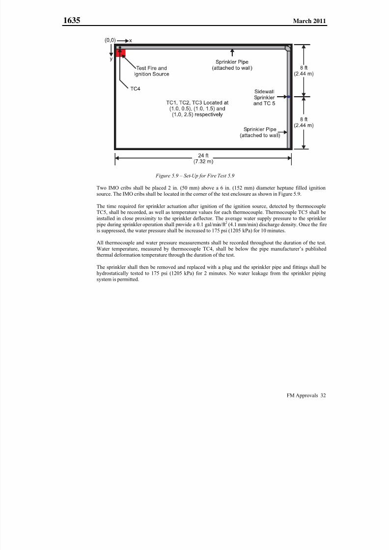
7/25/2019 Fm Approvals 1635 Std 2011
http://slidepdf.com/reader/full/fm-approvals-1635-std-2011 36/55
1635 March 2011
FM Approvals 32
Figure 5.9 – Set-Up for Fire Test 5.9
Two IMO cribs shall be placed 2 in. (50 mm) above a 6 in. (152 mm) diameter heptane filled ignition
source. The IMO cribs shall be located in the corner of the test enclosure as shown in Figure 5.9.
The time required for sprinkler actuation after ignition of the ignition source, detected by thermocoupleTC5, shall be recorded, as well as temperature values for each thermocouple. Thermocouple TC5 shall be
installed in close proximity to the sprinkler deflector. The average water supply pressure to the sprinkler
pipe during sprinkler operation shall provide a 0.1 gal/min/ft2 (4.1 mm/min) discharge density. Once the fire
is suppressed, the water pressure shall be increased to 175 psi (1205 kPa) for 10 minutes.
All thermocouple and water pressure measurements shall be recorded throughout the duration of the test.Water temperature, measured by thermocouple TC4, shall be below the pipe manufacturer’s publishedthermal deformation temperature through the duration of the test.
The sprinkler shall then be removed and replaced with a plug and the sprinkler pipe and fittings shall be
hydrostatically tested to 175 psi (1205 kPa) for 2 minutes. No water leakage from the sprinkler pipingsystem is permitted.
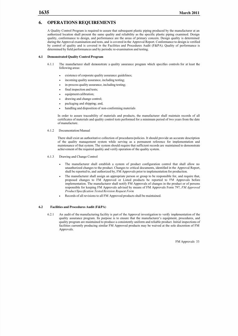
7/25/2019 Fm Approvals 1635 Std 2011
http://slidepdf.com/reader/full/fm-approvals-1635-std-2011 37/55
1635 March 2011
FM Approvals 33
6. OPERATIONS REQUIREMENTS
A Quality Control Program is required to assure that subsequent plastic piping produced by the manufacturer at an
authorized location shall present the same quality and reliability as the specific plastic piping examined. Design
quality, conformance to design, and performance are the areas of primary concern. Design quality is determined
during the Approval examination and tests, and is covered in the Approval Report. Conformance to design is verified by control of quality and is covered in the Facilities and Procedures Audit (F&PA). Quality of performance is
determined by field performances and by periodic re-examination and testing.
6.1 Demonstrated Quality Control Program
6.1.1 The manufacturer shall demonstrate a quality assurance program which specifies controls for at least thefollowing areas:
existence of corporate quality assurance guidelines;
incoming quality assurance, including testing;
in-process quality assurance, including testing;
final inspection and tests;
equipment calibration;
drawing and change control; packaging and shipping; and,
handling and disposition of non-conforming materials
In order to assure traceability of materials and products, the manufacturer shall maintain records of allcertificates of materials and quality control tests performed for a minimum period of two years from the date
of manufacture.
6.1.2 Documentation/Manual
There shall exist an authoritative collection of procedures/policies. It should provide an accurate description
of the quality management system while serving as a permanent reference for implementation and
maintenance of that system. The system should require that sufficient records are maintained to demonstrate
achievement of the required quality and verify operation of the quality system.
6.1.3 Drawing and Change Control
The manufacturer shall establish a system of product configuration control that shall allow no
unauthorized changes to the product. Changes to critical documents, identified in the Approval Report,shall be reported to, and authorized by, FM Approvals prior to implementation for production.
The manufacturer shall assign an appropriate person or group to be responsible for, and require that,
proposed changes to FM Approved or Listed products be reported to FM Approvals before
implementation. The manufacturer shall notify FM Approvals of changes in the product or of persons
responsible for keeping FM Approvals advised by means of FM Approvals Form 797, FM Approved
Product/Specification Tested Revision Request Form
Records of all revisions to all FM Approved products shall be maintained.
6.2 Facilities and Procedures Audit (F&PA)
6.2.1 An audit of the manufacturing facility is part of the Approval investigation to verify implementation of the
quality assurance program. Its purpose is to ensure that the manufacturer’s equipment, procedures, and
quality program are maintained to produce a consistently uniform and reliable product. Initial inspections offacilities currently producing similar FM Approved products may be waived at the sole discretion of FM
Approvals.

7/25/2019 Fm Approvals 1635 Std 2011
http://slidepdf.com/reader/full/fm-approvals-1635-std-2011 38/55
1635 March 2011
FM Approvals 34
6.2.2 These audits shall be conducted at least annually by FM Approvals, or its designate, or more frequently
dependent on jurisdictional requirements. At issue of this standard the Occupational Safety and HealthAdministration (OSHA) of the United States Department of Labor requires audits of manufacturing sites
producing products for use in hazardous locations during each quarter the product is manufactured.
6.2.3 FM Approved products or services shall be produced or provided from the location(s) audited by FM
Approvals and as specified in the Approval Report. Manufacture of products bearing the FM Approvals
Certification Mark is not permitted at any other location without prior written authorization by FMApprovals.
6.3 Manufacturer’s Responsibilities
6.3.1 The manufacturer shall notify FM Approvals of changes in product construction, design, components, raw
materials, physical characteristics, coatings, component formulation or quality assurance procedures prior to
implementation of such changes.
6.3.2 Where all or part of the quality control has been subcontracted, the manufacturer shall, at a minimum,
conduct sufficient oversight audits to verify the continued application of the required controls.
6.4 Manufacturing and Production Tests
The manufacturer shall measure and record critical component dimensions, material thickness, and markings (as
applicable) at the beginning of each production run. Thereafter, these measurements shall be recorded every 4 hours.The number of samples to be measured shall be based on the manufacturer’s Quality Control Manual, but in no case
shall be less than five samples. Measurements shall be compared to the latest revision of the component drawings.
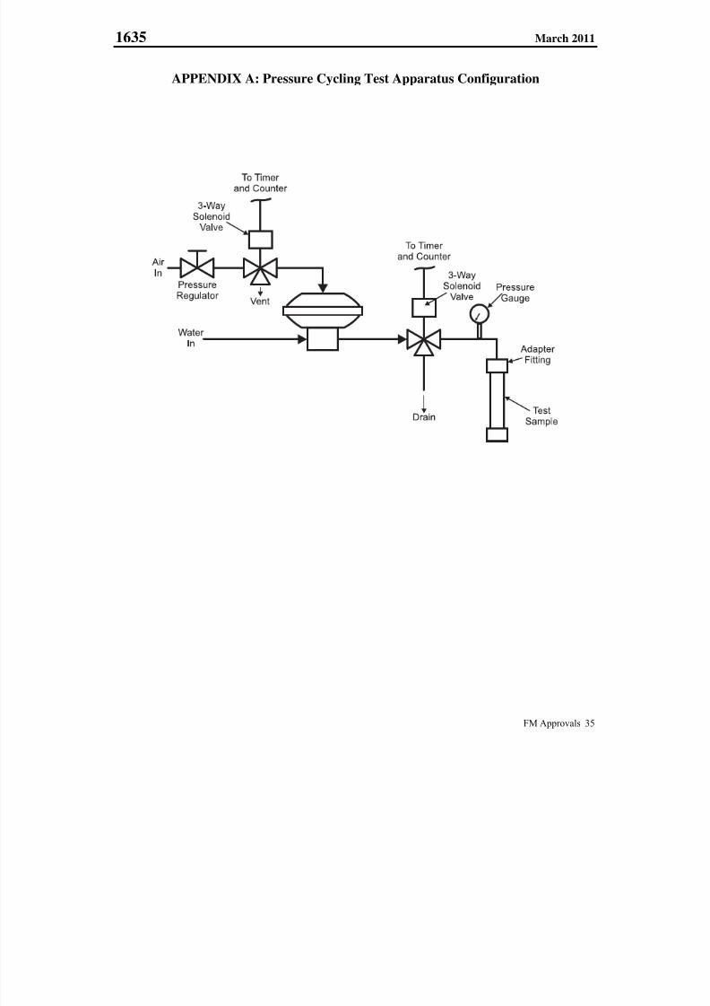
7/25/2019 Fm Approvals 1635 Std 2011
http://slidepdf.com/reader/full/fm-approvals-1635-std-2011 39/55
1635 March 2011
FM Approvals 35
APPENDIX A: Pressure Cycling Test Apparatus Configuration
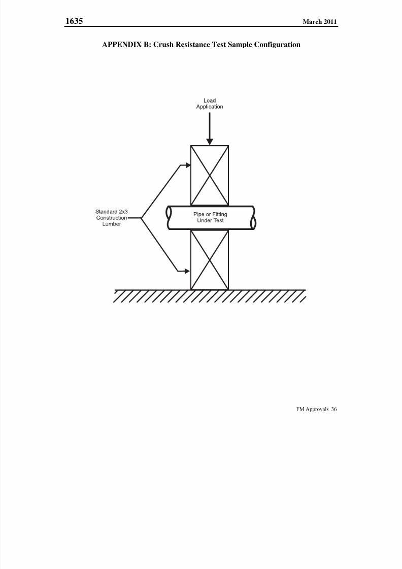
7/25/2019 Fm Approvals 1635 Std 2011
http://slidepdf.com/reader/full/fm-approvals-1635-std-2011 40/55
1635 March 2011
FM Approvals 36
APPENDIX B: Crush Resistance Test Sample Configuration
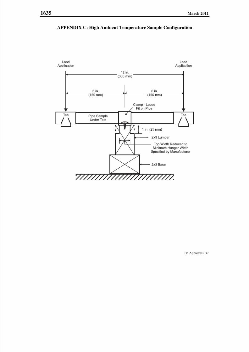
7/25/2019 Fm Approvals 1635 Std 2011
http://slidepdf.com/reader/full/fm-approvals-1635-std-2011 41/55
1635 March 2011
FM Approvals 37
APPENDIX C: High Ambient Temperature Sample Configuration
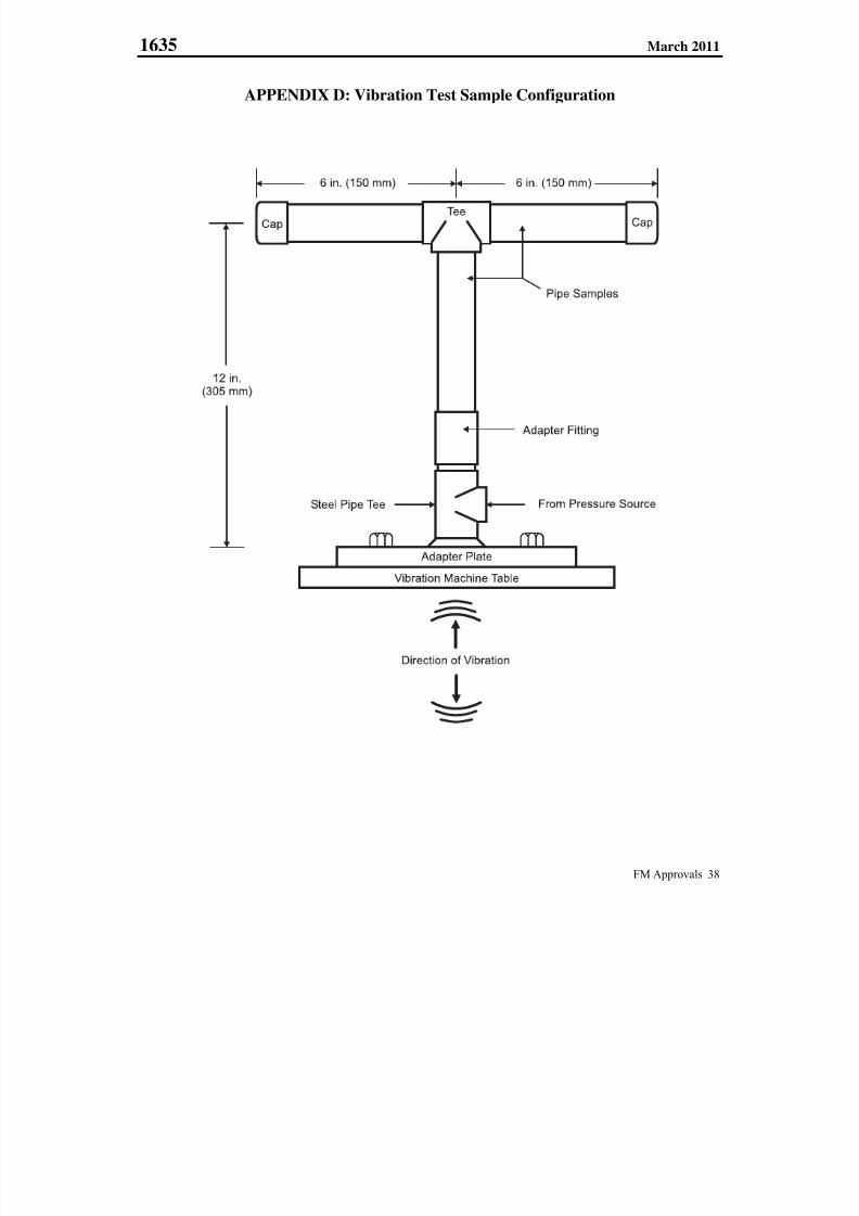
7/25/2019 Fm Approvals 1635 Std 2011
http://slidepdf.com/reader/full/fm-approvals-1635-std-2011 42/55
1635 March 2011
FM Approvals 38
APPENDIX D: Vibration Test Sample Configuration
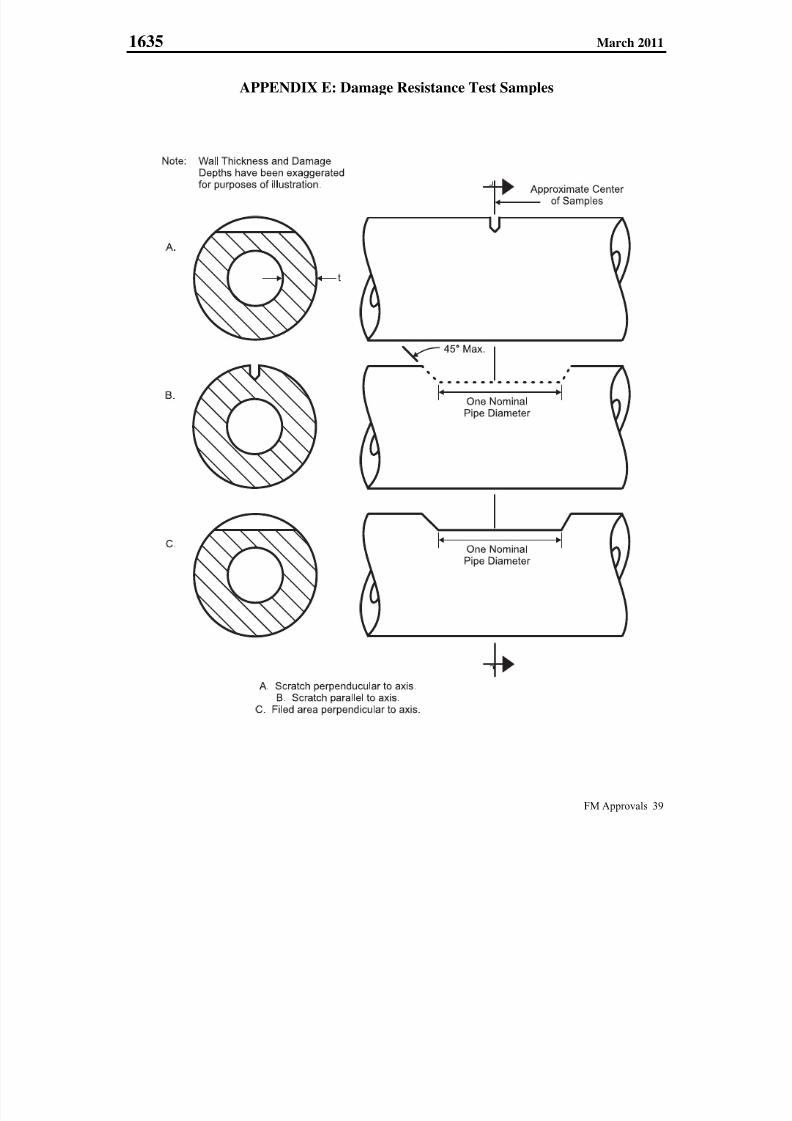
7/25/2019 Fm Approvals 1635 Std 2011
http://slidepdf.com/reader/full/fm-approvals-1635-std-2011 43/55
1635 March 2011
FM Approvals 39
APPENDIX E: Damage Resistance Test Samples
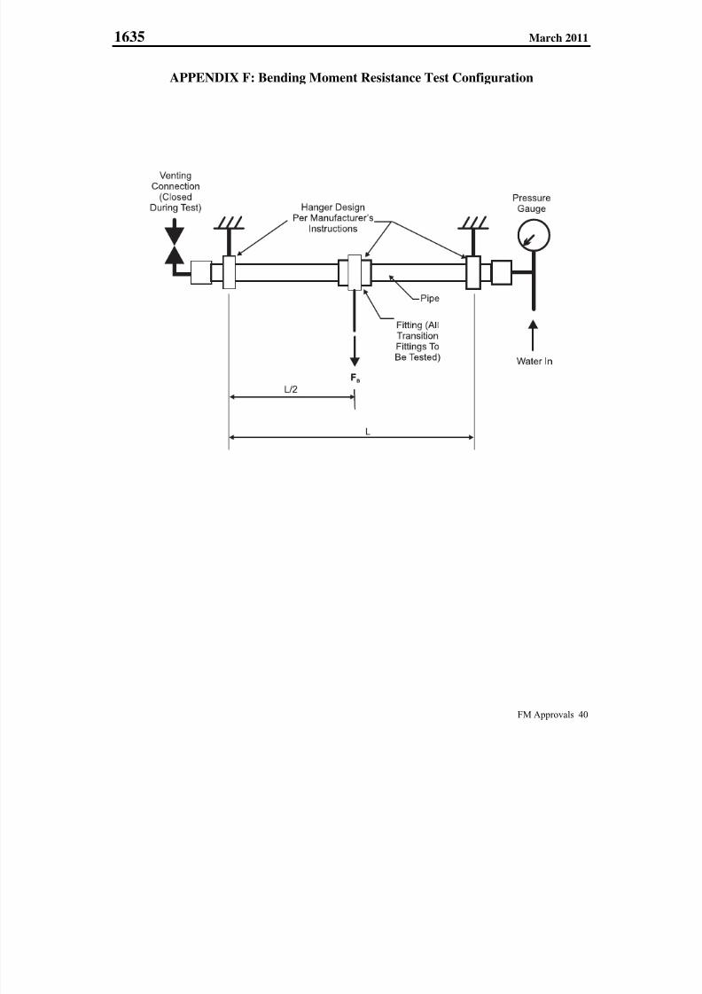
7/25/2019 Fm Approvals 1635 Std 2011
http://slidepdf.com/reader/full/fm-approvals-1635-std-2011 44/55
1635 March 2011
FM Approvals 40
APPENDIX F: Bending Moment Resistance Test Configuration
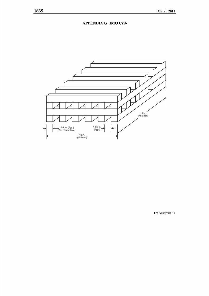
7/25/2019 Fm Approvals 1635 Std 2011
http://slidepdf.com/reader/full/fm-approvals-1635-std-2011 45/55
1635 March 2011
FM Approvals 41
APPENDIX G: IMO Crib

7/25/2019 Fm Approvals 1635 Std 2011
http://slidepdf.com/reader/full/fm-approvals-1635-std-2011 46/55
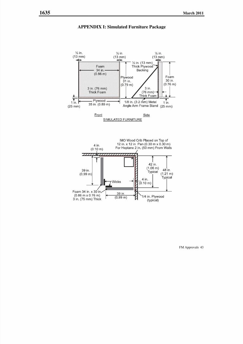
7/25/2019 Fm Approvals 1635 Std 2011
http://slidepdf.com/reader/full/fm-approvals-1635-std-2011 47/55
1635 March 2011
FM Approvals 43
APPENDIX I: Simulated Furniture Package

7/25/2019 Fm Approvals 1635 Std 2011
http://slidepdf.com/reader/full/fm-approvals-1635-std-2011 48/55
1635 March 2011
FM Approvals 44
APPENDIX J: Units of Measurement
FLOW: gal/min – “gallons per minute”; (L/min – “liters per minute”)
L/min = gal/min x 3.7854
FORCE: lbf – “pounds force”; (N – “Newtons”) N = lbf x 4.4482
FREQUENCY: Hz – “hertz”
K-FACTOR: gal/min/(psi)1/2 – “gallons per minute per square root of pounds per square inch”
(L/min/(kPa)1/2 – “liters per minute per square root of kilopascals”
(L/min/(kPa)1/2 = gal/min/(psi)1/2 x 1.442
LENGTH: in. – “inches”; (mm – “millimeters”)
mm = in. x 25.4
ft. – “feet”; (m – “meters”)m = ft. x 0.3048
MASS: lb – “pounds”; (kg – “kilograms”)lb = kg x 0.4536
PRESSURE: psi – “pounds per square inch”; (kPa – “kilopascals”)
kPa – psi x 6.8948
psf – “pounds per square foot”; (kPa – “kilopascals”)kPa = psf x 0.0479
bar = psi x 0.06895
VOLUME PER
UNIT AREA: gal/min/ft2 – "gallons per minute per square feet" (mm/min – "millimeters perminute")
mm/min = 40.75 x gal/min/ft2
TEMPERATURE: F – “degrees Fahrenheit”; (C – “degrees Celsius”)
C = (F – 32) x 0.556

7/25/2019 Fm Approvals 1635 Std 2011
http://slidepdf.com/reader/full/fm-approvals-1635-std-2011 49/55
1635 March 2011
FM Approvals 45
APPENDIX K: FM Approvals Certification Marks
FM Approvals certification marks are to be used only in conjunction with products or services that have been FM
Approved by FM Approvals and shall be in adherence with usage guidelines.
FM APPROVED mark:Authorized by FM Approvals as a certification mark for any product that has been FMApproved. There is no minimum size requirement for the mark, but it must be large enough
to be readily identifiable. The mark should be produced in black on a light background, or
in reverse on a dark background.
FM APPROVED mark with "C" only:
Authorized by FM Approvals as a certification mark for any product that has been
evaluated by FM Approvals in accordance with Canadian codes and standards. There is no
minimum size requirement for the mark, but it must be large enough to be readilyidentifiable. The mark should be produced in black on a light background, or in reverse on
a dark background.
FM APPROVED mark with "C" and "US":
Authorized by FM Approvals as a certification mark for any product that has been
evaluated by FM Approvals in accordance with US and Canadian codes and standards.There is no minimum size requirement for the mark, but it must be large enough to be
readily identifiable. The mark should be produced in black on a light background, or in
reverse on a dark background.
Cast-On FM APPROVALS marks:
Where reproduction of the FM APPROVED mark described above is impossible becauseof production restrictions, use these modified versions of the FM APPROVED mark. There
is no minimum size requirement for the mark, but it must be large enough to be readilyidentifiable.
Downloadable art and other FM Approvals resources are available by visiting our Web
site at www.fmapprovals.com

7/25/2019 Fm Approvals 1635 Std 2011
http://slidepdf.com/reader/full/fm-approvals-1635-std-2011 50/55
1635 March 2011
FM Approvals 46
FM Approvals Certification Marks
Usage Guidelines
All FM Approvals certification marks are the sole
property of FM Approvals LLC (“FM Approvals”)
and are registered or the subject of applications for
registration in the United States and many othercountries. They are for use only according to theseguidelines.
FM Approvals certification marks may be usedonly on FM Approved products and related
product packaging, in advertising material,
catalogs and news releases. Use of FM Approvals
certification marks on such material is not asubstitute for use of the complete FM Approvals
certification mark on FM Approved products
and/or product packaging.
No FM Approvals certification mark or aspect
thereof may be incorporated as part of a business
name, Internet domain name, or brandname/trademark for products/product lines. Thisincludes both design aspects (the FM Approvals
“diamond,” etc.) and word aspects (“FM,”
“Approved,” etc.). The use of any FM Approvals
certification mark as a trademark is strictly prohibited.
The Approval Standard number or class number
may not be incorporated as part of a businessname, Internet domain name, or brand
name/trademark for products/product lines. For
example, a company may not say “ABC
Company’s 4100 Fire Door is FM Approved”; the
proper terminology is, “ABC Company’s FireDoor is FM Approved per Approval Standard4100.”
FM Approvals certification marks, except for the
FM Approvals Quality System Registration mark,
may not be used on businessstationery/cards/signage because this could
mischaracterize the relationship with FM
Approvals. Additionally, these items should not
reference any FM Approvals certification mark.
Products or services may not be marketed under
any mark or name similar to “FM Global,” “FM
Approvals” or any of the FM Approvals
certification marks. Further, products or servicesmay not be marketed to imply a relationship
beyond the scope of any Approval made by FM
Approvals.
When an FM Approvals certification mark is used
in advertising material or on product packaging,
all material must reflect the specific circumstances
under which the product was FM Approved. Thematerial must clearly differentiate between
products that are FM Approved and those that are
not, and may not, in any way, imply a more
substantial relationship with FM Approvals.
A company may not reference the intent to submit
a product for Approval or the expectation that acompany will have a certain product FMApproved in the future. For example, a company
may not state, “Approval by FM Approvals
pending” or “Approval by FM Approvals applied
for.”
FM Approvals certification marks should not be
preceded or followed by a qualifier that indicates a
degree of certification or acceptability. Forexample, “exceeds,” “first” or “only” may not be
used to qualify any FM Approvals certification
mark.
Only original artwork issued by FM Approvals
should be used. The FM Approvals certificationmarks should not be altered in any way other thanto resize the artwork proportionately.
Unacceptable uses of the marks include, but are
not limited to, adding/deleting wording or artwork,
reducing the artwork to an illegible size, animationor distortion.
The text of the FM Approvals certification marks
may not be translated into any language other thanEnglish.
FM Approvals certification marks must appear ina size and location that is readily identifiable, but
less prominent than the name of the owner of the
certification or the manufacturer/seller/distributorof the certified products.

7/25/2019 Fm Approvals 1635 Std 2011
http://slidepdf.com/reader/full/fm-approvals-1635-std-2011 51/55
1635 March 2011
FM Approvals 47
APPENDIX L: Tolerances
Unless otherwise stated, the following tolerances shall apply:
Angle ± 2°
Frequency (Hz) ± 5 percent of value
Length ± 2 percent of value
Volume ± 5 percent of value
Volume Per Unit Area ± 5 percent of value
Pressure ± 5 psi (35 kPa)
Temperature ± 4°F (2°C)
Time + 5/–0 seconds
+0.1/–0 minutes
Unless stated otherwise, all tests shall be carried out at a room (ambient) temperature of 68 ± 9°F (20 ± 5°C).
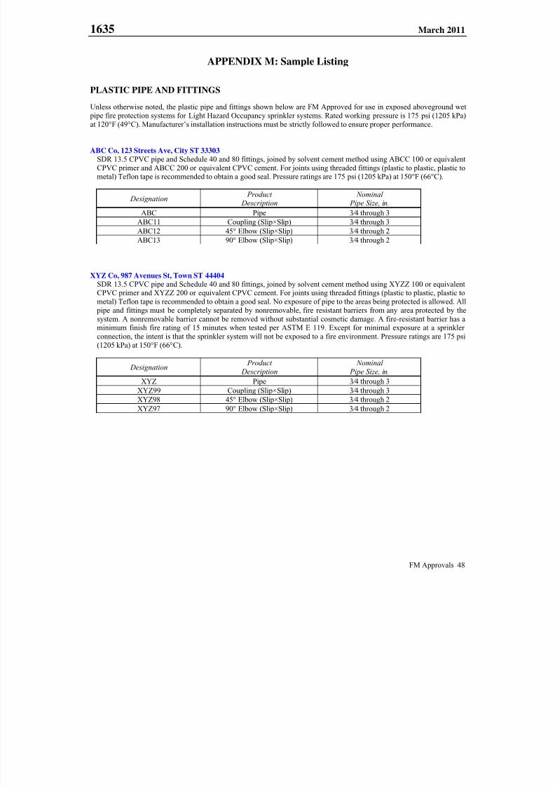
7/25/2019 Fm Approvals 1635 Std 2011
http://slidepdf.com/reader/full/fm-approvals-1635-std-2011 52/55
1635 March 2011
FM Approvals 48
APPENDIX M: Sample Listing
PLASTIC PIPE AND FITTINGS
Unless otherwise noted, the plastic pipe and fittings shown below are FM Approved for use in exposed aboveground wet
pipe fire protection systems for Light Hazard Occupancy sprinkler systems. Rated working pressure is 175 psi (1205 kPa)at 120°F (49°C). Manufacturer’s installation instructions must be strictly followed to ensure proper performance.
ABC Co, 123 Streets Ave, City ST 33303
SDR 13.5 CPVC pipe and Schedule 40 and 80 fittings, joined by solvent cement method using ABCC 100 or equivalent
CPVC primer and ABCC 200 or equivalent CPVC cement. For joints using threaded fittings (plastic to plastic, plastic tometal) Teflon tape is recommended to obtain a good seal. Pressure ratings are 175 psi (1205 kPa) at 150°F (66°C).
Designation Product
Description Nominal
Pipe Size, in.
ABC Pipe 3 ⁄ 4 through 3
ABC11 Coupling (Slip×Slip) 3 ⁄ 4 through 3
ABC12 45° Elbow (Slip×Slip) 3 ⁄ 4 through 2ABC13 90° Elbow (Slip×Slip) 3 ⁄ 4 through 2
XYZ Co, 987 Avenues St, Town ST 44404
SDR 13.5 CPVC pipe and Schedule 40 and 80 fittings, joined by solvent cement method using XYZZ 100 or equivalentCPVC primer and XYZZ 200 or equivalent CPVC cement. For joints using threaded fittings (plastic to plastic, plastic to
metal) Teflon tape is recommended to obtain a good seal. No exposure of pipe to the areas being protected is allowed. All
pipe and fittings must be completely separated by nonremovable, fire resistant barriers from any area protected by the
system. A nonremovable barrier cannot be removed without substantial cosmetic damage. A fire-resistant barrier has aminimum finish fire rating of 15 minutes when tested per ASTM E 119. Except for minimal exposure at a sprinkler
connection, the intent is that the sprinkler system will not be exposed to a fire environment. Pressure ratings are 175 psi
(1205 kPa) at 150°F (66°C).
Designation Product
Description
Nominal
Pipe Size, in.
XYZ Pipe 3 ⁄ 4 through 3
XYZ99 Coupling (Slip×Slip) 3 ⁄ 4 through 3
XYZ98 45° Elbow (Slip×Slip) 3 ⁄ 4 through 2
XYZ97 90° Elbow (Slip×Slip) 3 ⁄ 4 through 2
7/25/2019 Fm Approvals 1635 Std 2011
http://slidepdf.com/reader/full/fm-approvals-1635-std-2011 53/55
1635 March 2011
FM Approvals 49
APPENDIX N: Chemical Compatibility Test Protocol
Chemical Compatibility Test for Environmental Stress Cracking between Plastic Piping Products and Steel Pipe
with Antimicrobial (AMC) and/or Antibacterial Coatings/Films
If one of the intended uses of the plastic pipe and fittings is in hybrid sprinkler systems (i.e. plastic pipe connected tointernally coated steel pipe), evaluation of plastic pipe and fittings under this standard shall include chemical compatibilitytesting with all FM Approved manufacturer applied internally coated steel pipe (i.e. internally coated by the manufacturer)
in accordance with Appendix N.
Requirement
When exposed to a solution of deionized (DI) water and the extract from Antimicrobial (AMC) or Antibacterial
coated steel pipe, tensile Type V specimens of plastic pipe shall not experience an average reduction of more than 20
percent in Tensile Stress at Yield nor an average reduction of more than 50 percent in Elongation at Break whencompared to unexposed control specimens. There shall be no cracks or crazes visually observable on the tensile
surface of exposed specimens for all exposure periods. Results of this testing will be reported as PASS or FAIL in
the applicable test documentation. When testing is required for compatibility with plastic fittings only, special
considerations will be given to the shape of the test samples and will be determined by FM Approvals at the time of project initiation.
Test/Verification
Deionized (DI) water shall be used to extract antibacterial or antimicrobial coatings from the inside surfaces of all
currently FM Approval steel sprinkler pipe with Antimicrbial (AMC) or Antibacterial Coatings/Films in accordance
with the following procedure:
Place a cut section of 2 mil (0.002 in.) thickness Teflon® PTFE film on one end of a 5 ft (1.52 m) long 3 in.
(75 mm) NPS piece of coated pipe.
Cover the Teflon® PTFE film with a 3 in. (75 mm) rubber end cap, and fit an end cap on the end of the pipe.
Tighten the hose clamp on the rubber end cap to prevent water leakage.
Place the pipe in the upright position, with the sealed cap located at the bottom.
Pour five liters of DI water into the open end of the pipe.
Seal the open end of the pipe with a second section of Teflon film and a second rubber end cap/hose clamp.
Place the pipe horizontally on a suitable apparatus that will allow constant rotation of the pipe for a period of
10 days at a rotation rate of 44 +/- 2 revolutions per minute (RPM).
At the completion of the 10 day extraction period, remove the DI water extract from the pipe and collect for
subsequent exposure testing of CPVC / plastic pipe samples.
Type V Tensile Specimens shall be machined from 1 inch NPS chlorinated polyvinyl chloride (CPVC) or other
plastic pipe being considered for FM Approval in hybrid fire sprinkler systems with steel pipes with antimicrobial or
antibacterial coatings.
The dimensions of Type V tensile specimens are shown in Figure N-1 for a 1 inch NPS specimen of 13.5 SDRCPVC pipe made in accordance with ASTM F442-09. Dimensions of the Type V-tensile specimens may vary
based on pipe thickness. The fabrication of Type V tensile specimens is to be in accordance with
ASTM D638-08.
Due to the limited dimensions of 1 inch NPS CPVC pipe, and potentially other plastic pipes, it is necessary to
machine the length of 2.500 inch tensile specimen along the longitudinal axis of the 1 inch NPS CPVC or other
plastic pipe as shown in Figure N-2 for fabrication of the Type V tensile specimens.
The cut edges of the machined surfaces shall be made smooth by finishing with No. 320 or finer sandpaper.
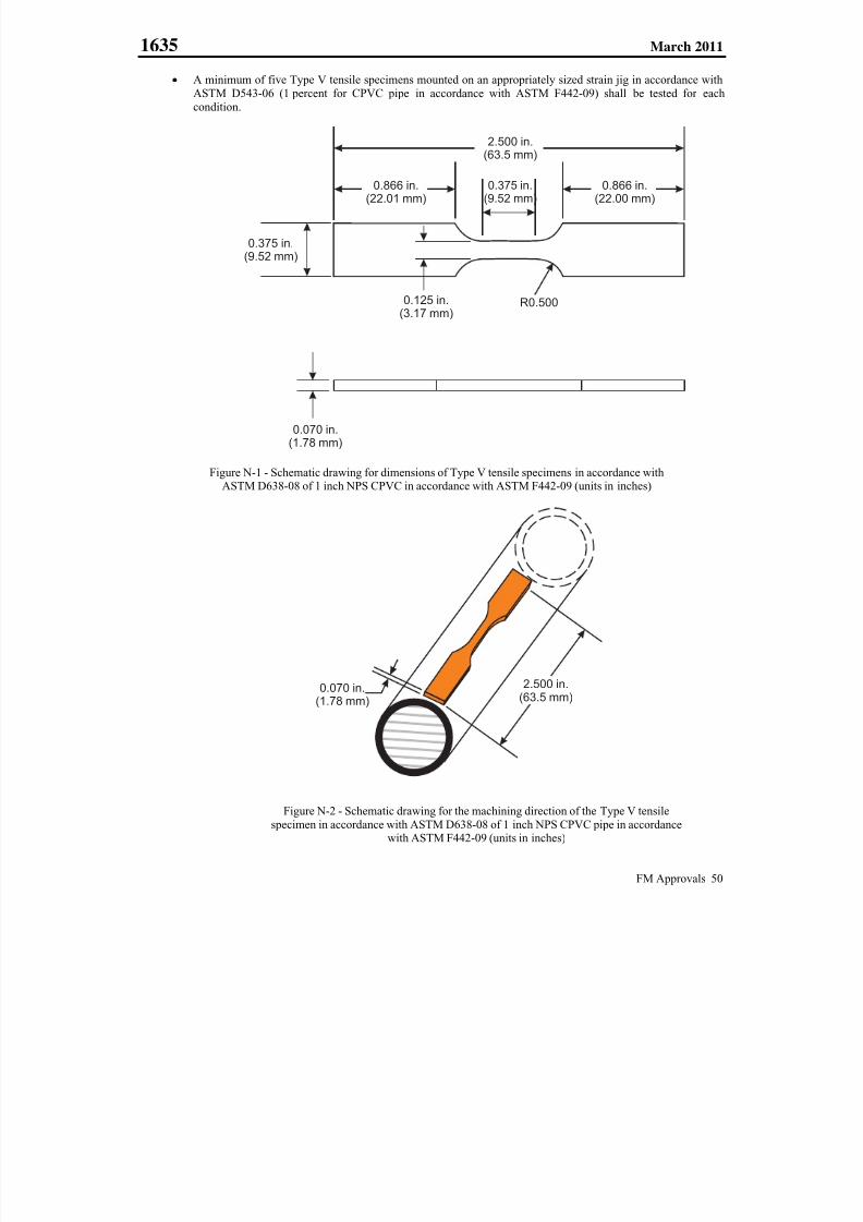
7/25/2019 Fm Approvals 1635 Std 2011
http://slidepdf.com/reader/full/fm-approvals-1635-std-2011 54/55
1635 March 2011
FM Approvals 50
2.500 in.(63.5 mm)
0.375 in.(9.52 mm)
0.375 in.(9.52 mm)
0.070 in.(1.78 mm)
0.125 in.(3.17 mm)
R0.500
0.866 in.(22.00 mm)
0.866 in.(22.01 mm)
A minimum of five Type V tensile specimens mounted on an appropriately sized strain jig in accordance with
ASTM D543-06 (1 percent for CPVC pipe in accordance with ASTM F442-09) shall be tested for each
condition.
Figure N-1 - Schematic drawing for dimensions of Type V tensile specimens in accordance withASTM D638-08 of 1 inch NPS CPVC in accordance with ASTM F442-09 (units in inches)
Figure N-2 - Schematic drawing for the machining direction of the Type V tensile
specimen in accordance with ASTM D638-08 of 1 inch NPS CPVC pipe in accordancewith ASTM F442-09 (units in inches)
2.500 in.(63.5 mm)
0.070 in.(1.78 mm)

7/25/2019 Fm Approvals 1635 Std 2011
http://slidepdf.com/reader/full/fm-approvals-1635-std-2011 55/55
1635 March 2011
Strain fixture operation and tensile properties’ measurements shall be conducted in accordance with the following procedure.
Mount 5 Type V tensile specimens on an appropriately sized strain fixture in accordance with ASTM D543-08(1 percent for 1 inch NPS CPVC pipe per ASTM F442-09). Ensure that at least 0.7 in. (18 mm) of close contact
along every specimen’s gage length and fixture surface is maintained, and specimens do not touch each other. It
should be noted that the top surface of the Type V tensile specimen mounted on the strain fixture shall be theinside surface (water side) of the CPVC / plastic pipe.
Prepare four sets of mounted strain fixtures for each type of DI water extract exposure. Three sets of strainfixtures are used for exposure testing and one set is used to test as the control sample (i.e. DI exposure only).
Place the mounted strain fixture in a glass jar with 400 ml of the DI water extract, and ensure that the fixtures
are fully immersed in the extract for test periods of 1 week, 2 weeks, and 4 weeks.
To ensure good chemical contact between Type V tensile specimens and the DI water extract throughout
exposure period, the liquid in the glass containers should be stirred once daily during the first week of exposureand once each week subsequently.
After 1 week, 2 weeks, and 4 weeks of exposure, remove the applicable exposed Type V tensile specimens from
the strain fixtures and measure the tensile properties in accordance with ASTM D638-08. After 1 week of
exposure, remove the unexposed control specimens and measure the tensile properties in accordance withASTM D638-08.
Test specimens within 24 hours after being removed from the strain fixture.
The nominal strain rate in tensile test shall be 1 mm/min (0.039 inch/min) for all exposure conditions in order to
have a consistent testing speed throughout the tests.
Average value with Standard deviation shall be calculated for the sample size of 5 test samples.
All specimens shall pass the Acceptance Criteria as shown below:
State of surface: There shall be no cracks or crazes visually observable on the tensile surface and edges ofexposed specimens for all specified exposure periods. Results of this testing will be reported as PASS or FAIL
in the applicable test documentation.
Tensile Strength at Yield: There shall be less than 20 percent reduction in the average value of the Tensile
Strength at Yield for exposed specimens vs. unexposed control specimens for all specified exposure periods.Results of this testing will be reported as PASS or FAIL in the applicable test documentation.
Elongation at Break: There shall be less than 50 percent reduction in the average value of the Elongation at
Break for exposed specimens vs. unexposed control specimens. Results of this testing will be reported as PASSor FAIL in the applicable test documentation.
Recommended