PATRAN 328 Exercise Workbook - Release 6.0 4-1
Freebody Analysis ofa Truss
X
Y
Z X
Y
Z
LESSON 4
Objectives:
■ Create the geometry for a simple truss
■ Perform a freebody analysis on the truss

4-2 PATRAN 328 Exercise Workbook - Release 6.0

LESSON 4 Freebody Analysis of a Truss
PATRAN 328 Exercise Workbook - Release 6.0 4-3
Suggested Exercise Steps:1. Open a new database namedtruss.db.
2. Create the geometry for the truss. The left edge will be 3units high and the right vertex will be located at [7, 5.5, 0].The cross bars will be created by making a line normal tothe bottom and copying it. The remaining cross bars will becreated by joining 2 points.
3. Create a mesh seed then mesh the truss withBar 2 elements.
4. Apply a vertical load of 235 at tip of the truss. Also apply amid-span load of 981.0 in the middle and constrain alldegrees of freedom on the left side.
5. Create a material and name itsteel. Give it anElasticModulusof 30E6, Poison’s Ration of 0.3 and aDensity of0.00029
6. Create an I-Beam usingElement Propertiesand theBeamLibrary and apply it to the truss
7. Analyze the model with MSC/NASTRAN making sure toselectGrid Point Force Balance as part of theOutputRequests.
8. Read in the .op2 results file and perform a freebdy analysison the model usingTools/Freebody Analysis.
Exercise Procedure:1. Create a new database namedtruss.db.
Click onOK when theNew Model Preferenceform appears.
2. Create the geometry for the truss.
You will start with the outside vertical edges.
File/New ...
New Database Name: truss
OK
Geometry
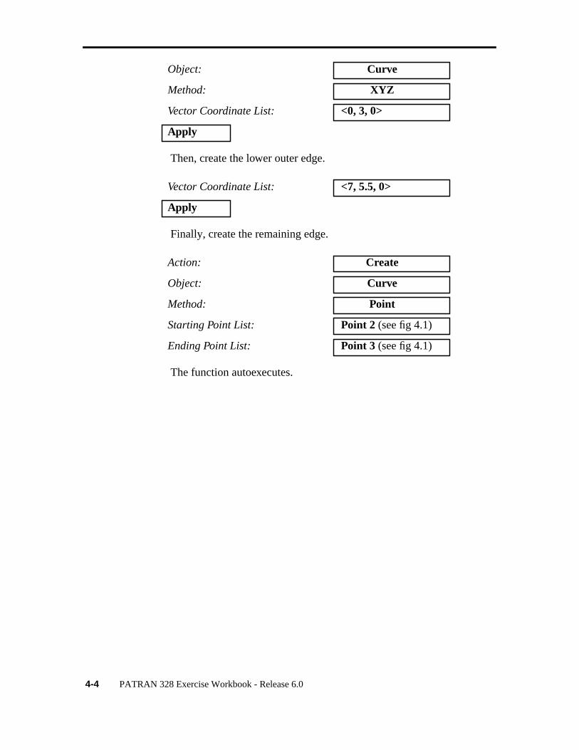
Action: Create
4-4 PATRAN 328 Exercise Workbook - Release 6.0
Then, create the lower outer edge.
Finally, create the remaining edge.
The function autoexecutes.
Object: Curve
Method: XYZ
Vector Coordinate List: <0, 3, 0>
Apply
Vector Coordinate List: <7, 5.5, 0>
Apply
Action: Create
Object: Curve
Method: Point
Starting Point List: Point 2 (see fig 4.1)
Ending Point List: Point 3 (see fig 4.1)

LESSON 4 Freebody Analysis of a Truss
PATRAN 328 Exercise Workbook - Release 6.0 4-5
Figure 4.1
Now you will create the inner cross beams of the truss
The function autoexecutes. Now use the curve you just created tomake 3 more parallel to it and alongCurve 2.
Action: Create
Object: Curve
Method: Normal
Point List: Point 2
Curve List: Curve2 (see fig 4.1)
Action: Transform
Object: Curve
Method: Translate
X
Y
Z X
Y
Z
Point 2
Point 3
Curve 2

4-6 PATRAN 328 Exercise Workbook - Release 6.0
Since you want the curves to follow alongCurve 2 then you mustmake yourTranslation Vectorfollow that too. Select theTip for aVector icon, then click onPoint 4. (See figure 4.2)
Figure 4.2
The function autoexecutes.
Trim the curves so they do not extend outside the truss.
Repeat Count: 3
Translation Vector:
Curve List: Curve 4
Action: Edit
Object: Curve
Tip for Vector withBase at [0, 0, 0]
X
Y
Z X
Y
Z
Point 4
Curve 4

LESSON 4 Freebody Analysis of a Truss
PATRAN 328 Exercise Workbook - Release 6.0 4-7
This command works by selecting the point to cut at,Trim Point List,then selecting the curve to cut and the end point of the side you wishto delete. First,to define the trim point select theCurve Intersect icon,Then click onCurve 3 andCurve 5.
Figure 4.3
The function autoexecutes.
Method: Trim
Trim Point List: See Figure 4.3
Curve to Trim/End Point: See Figure 4.3
X
Y
Z X
Y
Z
First click in theTrim PointList databox then selectCurve 3 andCurve 5
Secondly pick theCurve to Trim,Curve 5
Third, pick the End Pointof Curve 5 on the end youwould like to trim

4-8 PATRAN 328 Exercise Workbook - Release 6.0
To view the new curve click on the refresh graphics icon.
Repeat this procedure for Curves 6, 7
Now join all the cross beams by creating curves 8, 9, 10.
Figure 4.4
Action: Create
Object: Curve
Method: Point
Starting Point List: See Figure 4.4
Ending Point List: See Figure 4.4
X
Y
Z X
Y
Z
Starting Points
Ending Points
= Breaking Points
Curve 8
Curve 9
Curve 10

LESSON 4 Freebody Analysis of a Truss
PATRAN 328 Exercise Workbook - Release 6.0 4-9
To make meshing easier we will break the outer curves so that everycurve only meets another at its end point. Be sure to turn off theAutoExecutebutton.
When asked if you wish to delete the original curve, respondYes.
Now repeat this procedure forCurve 3
3. Now mesh the model
Action: Edit
Object: Curve
Method: Break
Delete Originals
Auto Execute
Curve List: Curve 2
Break Point: See Figure 4.4 ( BreakingPoints are denoted by thelarge circled points)
Apply
Yes
Finite Elements
Action: Create
Object: Mesh Seed
Type: Uniform
Number = 1
Curve List: Select all on Screen
Apply
Action: Create
Object: Mesh
Type: Curve

4-10 PATRAN 328 Exercise Workbook - Release 6.0
4. We have created the geometry and FEM. Now we will applytheLoad and Boundary Conditions.
There will be 3LBC sets. A vertical load applied at the tip of the truss,a mid-span load applied near the center of mass and constraints on allDegrees of Freedom where the truss is attached to a fixed surface.
Note: TheNode/Element ids may be different than shown below
Figure 4.5
Element Topology: Bar 2
Curve List: Select all on Screen
Apply
Action: Equivalence
Object: All
Type: Tolerance Cube
Apply
clamped_end
Node 6
Node 14

LESSON 4 Freebody Analysis of a Truss
PATRAN 328 Exercise Workbook - Release 6.04-11
First, create the load on the tip.
Then create the mid-span load.
Loads/BCs
Action: Create
Object: Force
Type: Nodal
New Set Name: vertical_load
Input Data...
Force <F1 F2 F3>: <0, -235, 0>
OK
Select Application Region...
Geometry Filter: FEM
Select Nodes: Node 14
Add
OK
Apply
Action: Create
Object: Force
Type: Nodal
New Set Name: midspan_load
Input Data...
Force <F1 F2 F3>: <0, -981, 0>
OK
Select Application Region...
Geometry Filter: FEM
Select Nodes: Node 6
Add

4-12 PATRAN 328 Exercise Workbook - Release 6.0
Finally constrain the left edge from moving in all directions
OK
Apply
Action: Create
Object: Displacement
Type: Nodal
New Set Name: clamped_end
Input Data...
Translations <T1 T2 T3>: <0, 0, 0>
Rotations <R1 R2 R3>: <0, 0, 0>
OK
Select Application Region...
Geometry Filter FEM
Select Nodes: Screen select the leftedge of the model (seefig 5.5)
Add
OK
Apply

LESSON 4 Freebody Analysis of a Truss
PATRAN 328 Exercise Workbook - Release 6.04-13
Your model should look like the following:
5. Create a material and name itsteel.
Materials
Action: Create
Object: Isotropic
Method: Manual Input
New Material Name: steel
Input Properties...
Elastic Modulus: 30E6
Poison’s Ratio: 0.3
Density: 0.0029
X
Y
Z 123456
123456 981.0
235.0
X
Y
Z

4-14 PATRAN 328 Exercise Workbook - Release 6.0
6. Now you will define theElement Properties.
Click on theBeam Library icon
Click on the I-beam icon
Enter this information in the proper databoxes
To preview the I-beam’s shape click on
Apply
Cancel
Properties
Action: Create
Object: 1D
Method: Beam
Property Set Name: beam_elem_props
Input Properties...
Action: Create
Type: Standard Shape
New Section Name: i_beam
H = 0.3 t = .03
W1 = 0.3 t1 = .02
W2 = 0.3 t2 = .02
Calculate/Display
Create Sections
Beam Library

LESSON 4 Freebody Analysis of a Truss
PATRAN 328 Exercise Workbook - Release 6.04-15
The I-Beam should look like this
Close this display.
Fill out theInput Properties form with the following information:
In the Bar Orientationdatabox you must enter a vector in the XYplane because the model is in that plane. Type in<1 1 0>and clickOK.
Close
OK
Use Beam Section
Material Name: m:steel
Bar Orientation: <1, 1, 0>
OK

4-16 PATRAN 328 Exercise Workbook - Release 6.0
Click in Select Members data box, then on theBeam Elementiconthen select all on screen
Check the orientation of the beams you just created.
Select Members: Select all on Screen
Add
Apply
Display/Load/BC/Elem.Props...
Load/BC’s Hide All
Beam Display 2D mid-span
Apply
Beam Element

LESSON 4 Freebody Analysis of a Truss
PATRAN 328 Exercise Workbook - Release 6.04-17
Move the model around with the middle mouse button. Your viewportshould look something like this
When you are done previewing the model change theBeam Displayback to1D-Line then hitApply andCancel.
7. Now you will submit the model for analysis.
Analysis
Action: Analyze
Object: Entire Model
Method: Analysis Deck
Translation Parameters...
OUTPUT2 Format: Text
MSC/NASTRAN Version: 69
X
Y
ZX
Y
Z

4-18 PATRAN 328 Exercise Workbook - Release 6.0
This will create a file calledtruss.bdf. You will then submit this file tothe MSC/NASTRAN v.69 solver by typingnastran truss.bdf at yourUNIX prompt.
8. Once the analysis is finished you will read in the results filetruss.op2.
9. Now you will use theFreebody Resultsoption to view theforces on the truss.
OK
SolutionType...
Solution Type: Linear Static
OK
Subcase Create...
Available Subcases: Default
Output Requests...
Form Type: Basic
Select Result Type: Grid Point Force Balance
OK
Apply
Cancel
Apply
Analysis
Action: Read Output2
Object: Result Entities
Method: Translate
Select Results File...
truss.op2
OK
Apply

LESSON 4 Freebody Analysis of a Truss
PATRAN 328 Exercise Workbook - Release 6.04-19
Display the applied loads on the model.
Click on theSelect Results icon:
To change any of the display attributes of the vector plot select theDisplay Attributes icon:
Tools/Freebody Results...
Type: Loads
Select Result Case: Default
Select Result Type: Applied Loads
Apply
Select Results
Display Attributes

4-20 PATRAN 328 Exercise Workbook - Release 6.0
Your model should appear as follows:
Now display the reaction forces on the model.
Click on theSelect Results icon.
Again, to change any of the display attributes of the vector plot selecttheDisplay Attributes icon:
Type: Loads
Select Result Case: Default
Select Result Type: Reaction Loads
Apply
X
Y
Z
981.00
235.00
X
Y
Z

LESSON 4 Freebody Analysis of a Truss
PATRAN 328 Exercise Workbook - Release 6.04-21
Your model should appear as follows:
Now display a freebody diagram.
Click on theSelect Results icon.
Click on theSelect Entities icon
Type: Loads
Select Result Case: Default
Select Result Type: Freebody Loads
X
Y
Z
1089.75
447.52
126.25
1447.52
X
Y
Z

4-22 PATRAN 328 Exercise Workbook - Release 6.0
Select the target entities required. If this step is skipped the entiremodel or whatever group is currently posted will be used as the targetentity. If the entire model is used only the reaction and applied loadswill be displayed. You may want to turn auto add off in order to findwhich elements and nodes that you want to select before they areadded to the list.
Note: Again, your element ids may be different.
If you selected the middle elements your model will look like thefollowing:
Now you will view the internal loads at a node or nodes. First click ontheSelect Resultsicon.
Select Elements Elm 3, 4, 9, 12, 16
Add
Apply
X
Y
Z
513.59
648.83
648.83
151.30 386.30
513.59
170.13
405.13
X
Y
Z

LESSON 4 Freebody Analysis of a Truss
PATRAN 328 Exercise Workbook - Release 6.04-23
Click on theSelect Entities icon
Your model should appear as follows:
Type: Loads
Select Result Case: Default
Select Result Type: Internal Loads
Select Elements Elm 3, 4, 9, 12, 16
Add
Apply
X
Y
Z
648.83
513.59
513.59
648.83
151.30
170.13
386.30
405.13
X
Y
Z
4-24 PATRAN 328 Exercise Workbook - Release 6.0
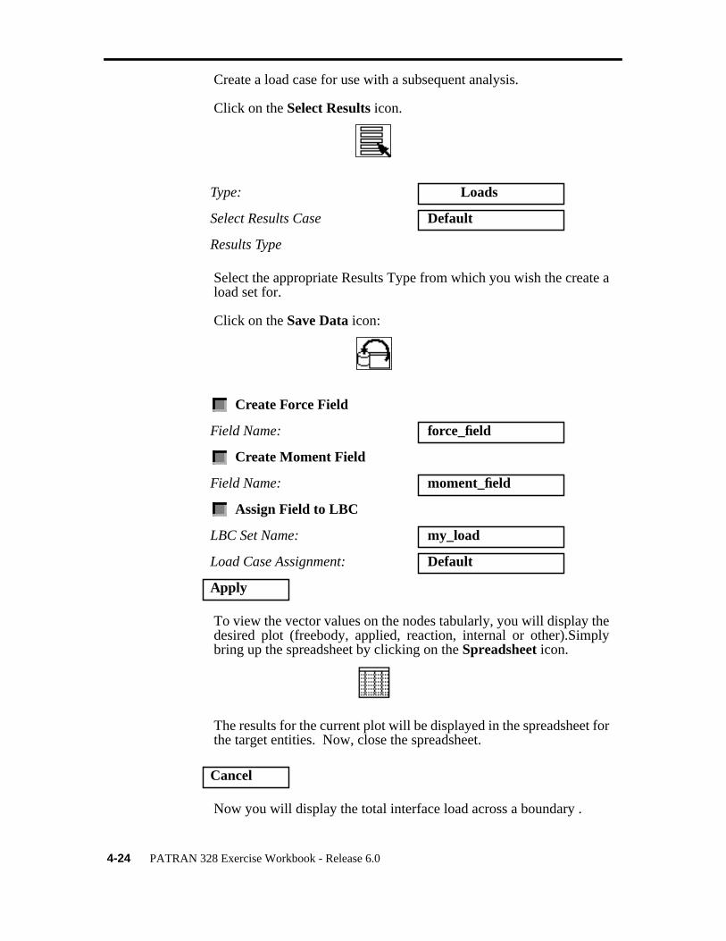
Create a load case for use with a subsequent analysis.
Click on theSelect Results icon.
Select the appropriate Results Type from which you wish the create aload set for.
Click on theSave Data icon:
To view the vector values on the nodes tabularly, you will display thedesired plot (freebody, applied, reaction, internal or other).Simplybring up the spreadsheet by clicking on theSpreadsheet icon.
The results for the current plot will be displayed in the spreadsheet forthe target entities. Now, close the spreadsheet.
Now you will display the total interface load across a boundary .
Type: Loads
Select Results Case Default
Results Type
Create Force Field
Field Name: force_field
Create Moment Field
Field Name: moment_field
Assign Field to LBC
LBC Set Name: my_load
Load Case Assignment: Default
Apply
Cancel

LESSON 4 Freebody Analysis of a Truss
PATRAN 328 Exercise Workbook - Release 6.04-25
Click on theSelect Results icon
Note: When selecting Node 8 be sure to click on theNode icon.
Type: Interface
Select Result Case: Default
Select Result Type: Freebody Loads
Summation Point: Node 8
X
Y
Z X
Y
Z
Node 8
Element 11

4-26 PATRAN 328 Exercise Workbook - Release 6.0
Click on theSelect Entities icon
The target entites must be all the nodes along a interface boundary forwhich you are interested in calculating the total load. In addition youmust select the element on one side of this node that defines theinterface line.
Your model should appear as follows:
Select by: Element
Select Elements: Element 11
Select by: Node
Select Nodes: Node 8
Add
Apply
X
Y
Z
54.88
292.44
X
Y
Z
Recommended