EN ISO 9001:2000
Certificate: 01 100 5695PNEUMATIC CLUTCH-BRAKES
FRENO-EMBRAGUES NEUMÁTICOS

EN ISO 9001:2000
Certificate: 01 100 5695
I N D E X
I N D I C E
Pag.
INTRODUCTION 2
CLUTCH-BRAKE SERIES 5.8
CLUTCH-BRAKE SERIES 5.7
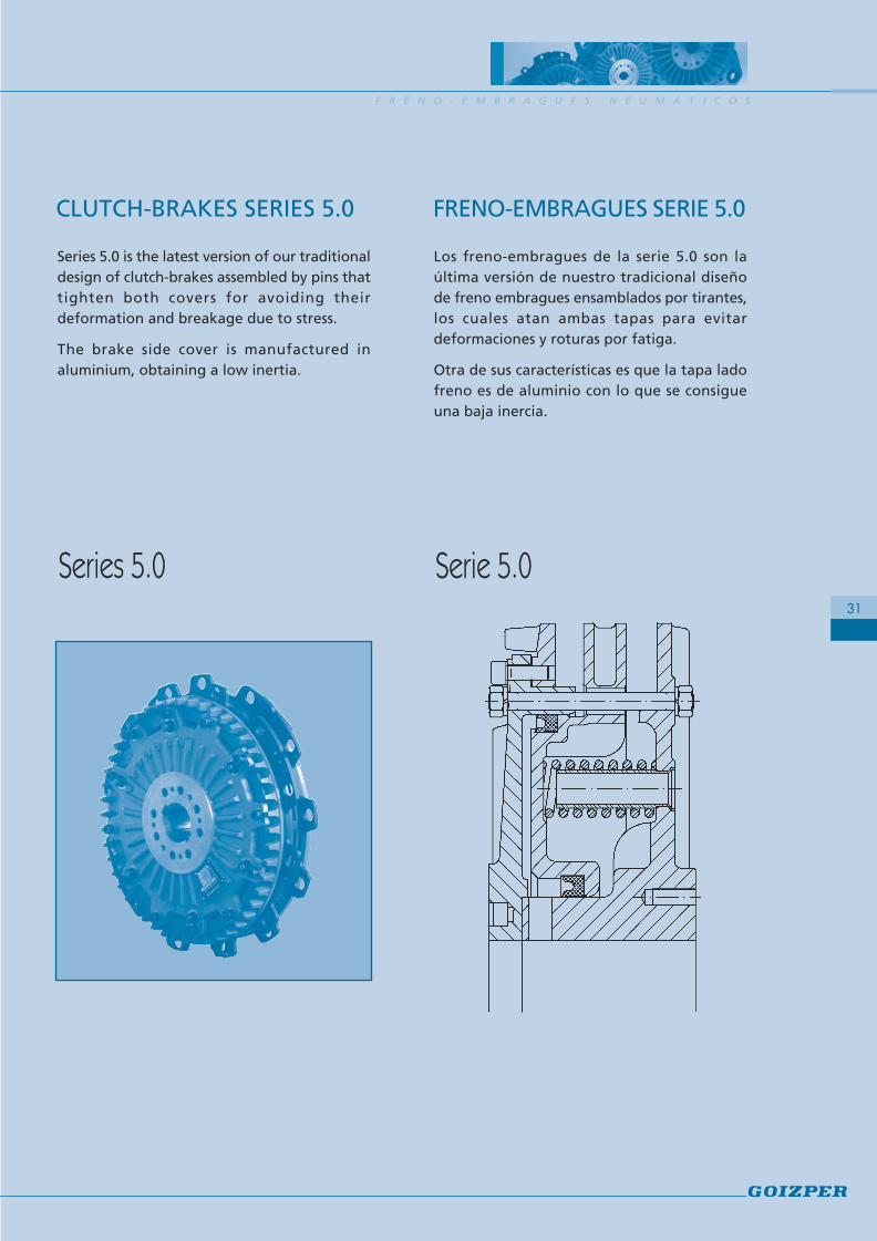
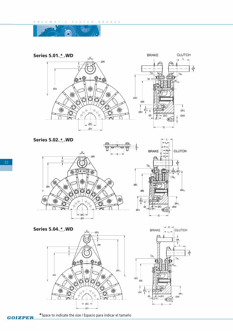
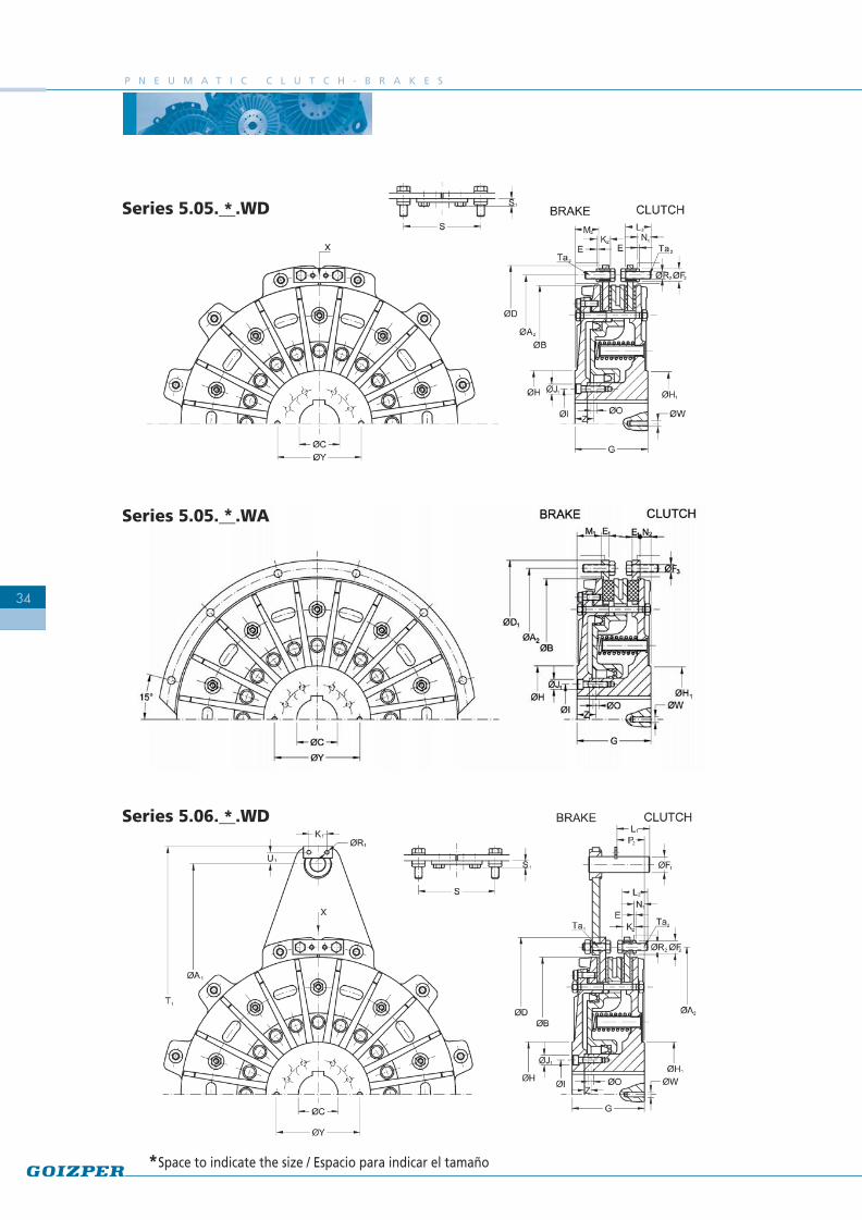
CLUTCH-BRAKE SERIES 5.0
CLUTCH-BRAKE SERIES 5.5 and 5.6
ACCESSORIES
PNEUMATIC CLUTCHES
TECHNICAL INFORMATION
15
23
31
39
45
48
PNEUMATIC SAFETY BRAKES 49
DEFINITIONSPERFORMANCE OF FRICTION MATERIALSBRAKING PROCESSTORQUE CALCULATION FOR AN ECCENTRIC PRESSPNEUMATIC SCHEME
37101213
WET CLUTCH-BRAKE SERIES 5.W
SPECIAL CLUTCH-BRAKE UNITS
51
55
Pag.
INTRODUCCIÓN 2
FRENO-EMBRAGUES SERIE 5.8
FRENO-EMBRAGUES SERIE 5.7
FRENO-EMBRAGUES SERIE 5.0
FRENO-EMBRAGUES SERIES 5.5 y 5.6
ACCESORIOS
EMBRAGUES NEUMÁTICOS
INFORMACIÓN TÉCNICA
15
23
31
39
45
48
FRENOS NEUMÁTICOS DE SEGURIDAD 49
DEFINICIONESCOMPORTAMIENTO DE LOS ELEMENTOS DE FRICCIÓNPROCESO DE FRENADOCÁLCULO DEL PAR EN UNA PRENSA EXCÉNTRICAESQUEMA NEUMÁTICO
37101213
FRENO-EMBRAGUES OLEONEUMÁTICOS SERIE 5.W
FRENO-EMBRAGUES ESPECIALES
51
55

C L U T C H - B R A K E S
2
INTRODUCTION
En el presente catálogo, dedicadoexclusivamente a nuestra línea de frenos,embragues, freno-embragues neumáticos,oleoneumáticos y sus accesorios, les ofrecemosnuestros modelos más actualizados de acuerdoa nuestros últimos desarrollos.
Dichos productos son empleados en maquinariapara corte y deformación metálica, tal comoprensas, cizallas, plegadoras, etc.
Se explican además los aspectos técnicos básicosrelacionados con los mismos: pares, tiemposde respuesta, comportamiento de los elementosde fricción, etc.
Este catálogo no es más que la referencia dealgunos de los productos que fabricamos. Siprecisaran de información adicionalrelacionada con dichos productos, no dudenen contactarnos.
INTRODUCCIÓN
This catalogue shows the full range of thepneumatic standard Goizper clutch-brakecombinations and accessories.
Applications include Metalforming Presses,Shears, Die Cutters, Forming Machines, andCan Body Makers.
We have added technical information to assistin the selection of our products.
This catalogue is a reference only. Please donot hesitate to contact us for specialapplications related to these products.
F R E N O - E M B R A G U E S
3
TECHNICAL INFORMATION
En este apartado se definen y explican losconceptos y fórmulas básicos necesarios para elcálculo y selección de los freno-embraguesadecuados para cada aplicación.
Las designaciones, símbolos en las fórmulas y lasunidades utilizadas en este catálogo siguen lasnormas VDI 2241 y / o la DIN1304, normas dereferencia para este tipo de productos.
En caso de cualquier duda, aclaración o interésen algún aspecto concreto, les rogamos se ponganen contacto con nuestro departamento técnico.
DEFINICIONES
PARES
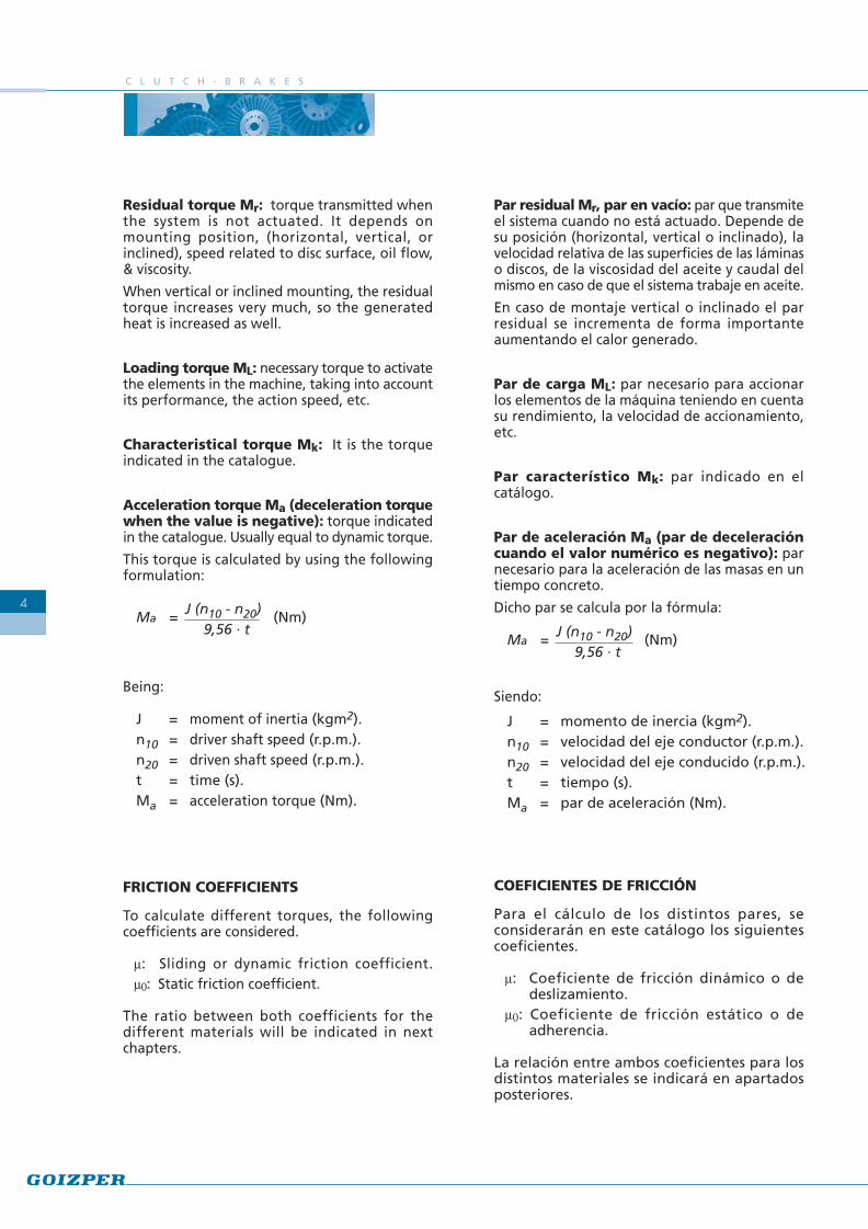
Primeramente es importante definir y distinguirlos distintos momentos o pares que se consideranen un proceso de embragado o frenado.El siguiente gráfico representa a cualquiera dedichos procesos:
Par de deslizamiento o par dinámico Ms: parque actúa una vez finalizado el tiempo de subidade par (t12). Varía durante el proceso de maniobray depende, entre otros factores, de la velocidadde deslizamiento y la temperatura de lassuperficies de fricción.
Par transmisible o par estático Mt: par máximoque admite el sistema actuado en función de lascondiciones de servicio y las condicionesmarginales del diseño, sin que se produzcaresbalamiento.
INFORMACIÓN TÉCNICA
Graph 1
This chapter explains the basic concepts andformulas for the calculation and selection ofclutch-brakes for each application.
All the formulas used in this catalogue are inaccordance with VDI 2241 and/or DIN 1304 norm.
In case of any doubt or if any further informationis required, please do not hesitate to contact ourTechnical Department.
DEFINITIONS
TORQUES
It is important to define and difference the torquesconsidered in the clutching or braking process.
The torque values shown in graph 1 are definedbelow.
Slip or dynamic torque Ms: this is the torquetransmitted once the torque increase time (t12)is finished. It changes within the cycle process anddepends, apart from other factors, on the slipspeed and the temperature of the friction surfaces.
Transmissible torque or static torque Mt:maximum admissible torque without slip,depending on the working and design conditions.
C L U T C H - B R A K E S
4
Par residual Mr, par en vacío: par que transmiteel sistema cuando no está actuado. Depende desu posición (horizontal, vertical o inclinado), lavelocidad relativa de las superficies de las láminaso discos, de la viscosidad del aceite y caudal delmismo en caso de que el sistema trabaje en aceite.
En caso de montaje vertical o inclinado el parresidual se incrementa de forma importanteaumentando el calor generado.
Par de carga ML: par necesario para accionarlos elementos de la máquina teniendo en cuentasu rendimiento, la velocidad de accionamiento,etc.
Par característico Mk: par indicado en elcatálogo.
Par de aceleración Ma (par de deceleracióncuando el valor numérico es negativo): parnecesario para la aceleración de las masas en untiempo concreto.
Dicho par se calcula por la fórmula:
Siendo:
COEFICIENTES DE FRICCIÓN
Para el cálculo de los distintos pares, seconsiderarán en este catálogo los siguientescoeficientes.
m: Coeficiente de fricción dinámico o dedeslizamiento.
m0: Coeficiente de fricción estático o deadherencia.
La relación entre ambos coeficientes para losdistintos materiales se indicará en apartadosposteriores.
Ma = J (n10 - n20) (Nm)9,56 · t
J = momento de inercia (kgm2).n10 = velocidad del eje conductor (r.p.m.).n20 = velocidad del eje conducido (r.p.m.).t = tiempo (s).Ma = par de aceleración (Nm).
Residual torque Mr: torque transmitted whenthe system is not actuated. It depends onmounting position, (horizontal, vertical, orinclined), speed related to disc surface, oil flow,& viscosity.
When vertical or inclined mounting, the residualtorque increases very much, so the generatedheat is increased as well.
Loading torque ML: necessary torque to activatethe elements in the machine, taking into accountits performance, the action speed, etc.
Characteristical torque Mk: It is the torqueindicated in the catalogue.
Acceleration torque Ma (deceleration torquewhen the value is negative): torque indicatedin the catalogue. Usually equal to dynamic torque.
This torque is calculated by using the followingformulation:
Being:
FRICTION COEFFICIENTS
To calculate different torques, the followingcoefficients are considered.
m: Sliding or dynamic friction coefficient.m0: Static friction coefficient.
The ratio between both coefficients for thedifferent materials will be indicated in nextchapters.
Ma = J (n10 - n20) (Nm)9,56 · t
J = moment of inertia (kgm2).n10 = driver shaft speed (r.p.m.).n20 = driven shaft speed (r.p.m.).t = time (s).Ma = acceleration torque (Nm).

F R E N O - E M B R A G U E S
5
TIME TERMS IN THE TORQUE TRANSMISSION
Like in the torques, it is important to definedifferent times existing in the torque transmissionthat appear in graph 1, which are:
Reaction delay t11: time from the activation ofthe control until the beginning of the torqueincrease.
Rising time t12: time from the beginning of thetorque increase until reaching the stationarycondition.
Link time t1: sum up of the reaction delay timeand the rising time.
t1 = t11 + t12
Slip time t3: time of relative movement betweenfriction surfaces of an actuated mechanism.
Total time tt: Time from the signal until thetorque transmission is accomplished.
tt = t11 + t3
TIME TERMS FOR INTERRUPTING THETORQUE TRANSMISSION (Graph 1)
We define the torque transmission interruptiontimes in a similar way than we have done in theprevious paragraph.
Reaction time when interrupting thetransmission t21: Time from the deactivation ofthe control until the beginning of the torquedecrease.
Decrease torque t22: Time from the torquedecrease until reaching 10% of the characteristicaltorque.
Disconnection time t2: Sum up of the reactiondelay and the decrease time.
t2 = t21+ t22
TÉRMINOS DE TIEMPO PARA ESTABLECERLA TRANSMISIÓN DEL PAR
De la misma forma que en el caso de los pares,es importante definir los diferentes tiemposexistentes en el proceso de transmisión del par,y que aparecen reflejados en el gráfico 1.Estos son:
Retardo de reacción al establecer latransmisión t11: tiempo desde la activacióndel mando hasta el comienzo de la subida delpar.
Tiempo de subida t12: tiempo desde elcomienzo de la subida del par hasta alcanzarel estado cuasi estacionario.
Tiempo de enlace t1: tiempo resultante de lasuma del retardo de reacción y el tiempo desubida.
t1 = t11 + t12
Tiempo de deslizamiento t3: tiempo duranteel cual tiene lugar un movimiento relativo entrelas superficies de fricción de un mecanismoactuado.
Tiempo total tt: tiempo desde que se da la señalhasta que se completa la transmisión del par.
tt = t11 + t3
TÉRMINOS DE TIEMPO PARA INTERRUMPIRLA TRANSMISIÓN DEL PAR (Gráfico 1)
Similarmente a lo indicado en el apartado anterior,se definen los distintos tiempos existentes en elproceso de interrupción de la trasmisión de par.
Retardo de reacción al interrumpir latransmisión t21: tiempo desde la desactivacióndel mando hasta el comienzo de la caída del par.
Tiempo de caída t22: tiempo desde el comienzode la caída del par hasta alcanzar el 10 % del parcaracterístico.
Tiempo de desconexión t2: suma del retardode reacción y el tiempo de caída.
Por tanto: t2 = t21+ t22

C L U T C H - B R A K E S
6
MOMENT OF INERTIA J
It is important to consider the moment of inertia“J” before making the folowing calculations.
For example, the moment of inertia of a solidiron cylinder which is 100mm thick with anouter diameter D (in mm) is obtained with thefollowing formulation:
J = 77 · D4 (kgm2)
When the moment of inertia is not referred tothe clutch shaft, it is necessary to reduce it tothis shaft. The following formulation is used.
Jred = J · i2 (kgm2)
J : moment of inertia of the shaft masses atany speed. (kgm2).
Jred : moment of inertia reduced to the clutchshaft (kgm2).
i : speed ratio between shafts.
i = n2
n1
n1 : cluth speed (r.p.m.).n2 : speed of the shaft with inertia J.
If the masses to accelerate have a linealmovement, their moments of inertia arereduced to the clutch shaft as per the followingformulation:
Jred = 91 · m · v2
(kgm2)n2
m : masses in lineal movement (kg).v : speed of the mentioned masses (m/s).Jred : moment of inertia reduced to the clutch
shaft (kgm2).
THERMAL CAPACITY
Concerning the heat transmission, the followingconcept is defined:
Work per engagement Q: It is the energycaused by friction and transformed into heat,as a consequence of engaging.
Q = J · (n10 ± n20)2· Mk (kJ)
182,4 · 103 Mk ± ML
J : moment of inertia (kgm2).Mk : transmissible torque (Nm).ML : loading torque (Nm).
MOMENTO DE INERCIA J
Es importante para los distintos cálculos quese indican posteriormente considerar elconcepto de momento de inercia “J”.
Así por ejemplo, el momento de inercia de uncilindro macizo de hierro de 100 mm de espesor,siendo su diámetro exterior D (en m), se obtienede la fórmula:
J = 77 · D4 (kgm2)
Cuando el momento de inercia no está referidoal eje del embrague, es necesario reducirlo adicho eje. Para ello se utiliza la siguientefórmula:
Jred = J · i2 (kgm2)
J : momento de inercia de las masas de uneje a una velocidad cualquiera (kgm2).
Jred : momento de inercia reducido al eje delembrague (kgm2).
i : relación de velocidades entre los ejes.
i = n2
n1
n1 : velocidad del embrague (r.p.m.).n2 : velocidad del eje con inercia J
Si las masas a acelerar tienen un movimientolineal, sus momentos se reducen al eje delembrague, por la siguiente fórmula:
Jred = 91 · m · v2
(kgm2)n2
m : masas en movimiento lineal (kg).v : velocidad de las citadas masas (m/s).Jred : momento de inercia reducido al eje del
embrague (kgm2).
CAPACIDAD CALORÍFICA
Desde el punto de vista de trasmisión de calorse define el siguiente concepto:
Trabajo de maniobra Q: energía transformadaen calor por la fricción a consecuencia de lamaniobra.
Q = J · (n10 ± n20)2· Mk (kJ)
182,4 · 103 Mk ± ML
J : momento de inercia (kgm2).Mk : par característico (Nm).ML : par de carga (Nm).

F R E N O - E M B R A G U E S
7
Type of clutch-brake Running Combination of materialsTipo de freno-embrague Medio Combinación de materiales
Pneumatic Dry Steel, cast iron/organic materialNeumático Seco Acero, hierro fundido / guarnición orgánica
Hydraulic-Wet Wet Tempered steel / sintered bronzeHidráulico-Oleoneumático En aceite Acero templado / sinterizado de bronce
The work produced by each cycle, which istransformed into heat, must be removedwithout surpassing the thermal capacity of theclutch-brake.
In the pneumatic clutch-brakes the heat isabsorbed by the elements of the clutch-brakeand transmitted to the air by the surfaces thatare in contact with the atmosphere.
In the hydraulic clutch-brakes, the heat isdissipated by means of lubrication oil.Lubrication can be done by splash, but whenan intense work is required a forced coolingwill be necessary, and lubrication will be donethrough the clutch-brake.
Depending on some factors, which we detailbelow, the friction coefficient can changeduring the clutch or brake engagement. Thesefactors also affect when the torque istransmitted without relative movement amongthe friction surfaces:
- Transmitted power.- Temperature on the friction surfaces
(cooling system).- Slip speed.- Combination of friction materials.- Dry or wet operation.- Design of the friction surfaces (grooves…)- Pressure in the friction surfaces- Ambient temperature.- .....
The combination of materials used in our clutch-brakes is the following:
PERFORMANCE OF FRICTIONMATERIALS
El trabajo producido en cada maniobra, quese transforma en calor, debe ser evacuado sinsobrepasar la capacidad calorífica del freno-embrague.
En los freno-embragues neumáticos el calor esabsorbido por los elementos del freno-embrague y transmitido al aire por lassuperficies que están en contacto con laatmósfera.
En los freno-embragues hidráulicos el calor esdisipado fundamentalmente por medio delaceite de refrigeración. La lubricación puederealizarse por barboteo, aunque en los casosde un trabajo intenso será necesaria unarefrigeración forzada, para lo cual larefrigeración se hará por el interior del freno-embrague.
La variación del coeficiente de fricción durantela maniobra de embragado (o frenado), asícomo cuando se transmite el par sinmovimiento relativo entre las superficies defricción, depende de numerosos factores, entrelos cuales podemos destacar:
- Potencia transmitida.- Temperatura en las superficies de fricción
(sistema de refrigeración).- Velocidad de deslizamiento.- Combinación de materiales de fricción.- Funcionamiento en seco o lubricado.- Diseño de las superficies de fricción (canales,
espirales...)- Presión en la superficie de fricción.- Temperatura del entorno.- .....
A continuación se indican las combinacionesde materiales utilizados habitualmente ennuestros freno-embragues:
COMPORTAMIENTO DE LOSELEMENTOS DE FRICCIÓN
C L U T C H - B R A K E S
8
PNEUMATIC CLUTCH-BRAKES:
These clutch-brakes work in dry condition andtherefore the friction materials are casting orsteel against organic asbestos-free material.
The friction surfaces are flat and the organiclinings are bonded to the discs, leaving someradial slots free that permit the removal ofcontaminants and heat. Organic friction blockscan also be used.
For a proper performance, the friction surfacesshould be free from grease and oil.
FRICTION COEFFICIENT
High friction coefficients are obtained (0,35 to0,45) with this combination of friction materials.In this case, there are no large differencesbetween the dynamic and static frictioncoefficients.
WEAR OF THE LININGS
Linings suffer wear. Wear is low when thetemperature of the metallic elements of theclutch-brake that are in contact with the liningdo not exceed a temperature of 170ºC. Abovethis temperature, wear increases considerably.
It is important to take into account theatmosphere temperature where the clutch-brake works, as well as its position in themachine. There must be enough space to permitthe flow of fresh air at the clutch-brake.
THERMAL CHARACTERISTICS
Organic linings are rated for 350ºC. Highertemperatures in short periods can be admissiblebut will incur in high wear.
The dissipation capacity with constant cyclingcan be between 0,7-1,4 J/mm2 min dependingon the factors indicated in the above headingcalled “performance of friction materials”.
The energy produced per cycle and per surfaceof the unit should not exceed 2J/mm2,consideration that will also be taken intoaccount when working in continuous mode.
FRENO-EMBRAGUES NEUMÁTICOS:
Dichos freno-embragues trabajan en seco, siendolos elementos de fricción acero o fundido frentea guarnición orgánica sin amianto.
En este tipo de freno-embragues las superficiesde fricción son lisas pero las guarniciones orgánicasvan pegadas a los discos porta-guarnicionesdejando entre sí unas ranuras radiales que sirvenpara la evacuación del abrasivo y del calor.También se pueden utilizar tacos de guarniciónorgánica alojados en los discos porta-tacos.
Es necesario mantener las superficies de fricciónlimpias de grasa y aceite para un correctofuncionamiento.
COEFICIENTE DE FRICCIÓN
Con esta combinación de materiales de fricciónse obtienen elevados coeficientes de fricción (0,35a 0,45) sin grandes diferencias entre el coeficientedinámico y el estático.
DESGASTE DE LAS GUARNICIONES
Las guarniciones están siempre sometidas adesgaste. Este desgaste es bajo, siempre que latemperatura de los elementos metálicos del freno-embrague que contactan con las guarniciones nosuperen aproximadamente 170 ºC. Por encima deesta temperatura el desgaste aumentaconsiderablemente.
Es importante tener en cuenta la temperaturaambiente del lugar donde trabaja el freno-embrague y su ubicación en la máquina, que debeestar provista de suficiente espacio y medios quepermitan la entrada libre de aire fresco a la zona.
CARACTERÍSTICAS TÉRMICAS
Las guarniciones orgánicas pueden admitirpuntualmente temperaturas de hasta 350ºC.Temperaturas más elevadas en periodos muycortos de tiempo pueden ser admisibles a costade un desgaste muy elevado.
El poder de disipación con cadencia constante demaniobras puede estar entre 0,7-1,4 J/mm2 mindependiendo de los factores señalados en elapartado anterior “comportamiento de loselementos de fricción”.
Además la energía producida por operación y porunidad de superficie no deberá pasar de 2 J/mm2,consideración que también se tendrá en cuentacuando el funcionamiento es en continuo.

F R E N O - E M B R A G U E S
Designed for wet operation, using temperedsteel against sintered bronze.
The friction surfaces have been designed withgrooves, taking into account (among otherfactors) the thermal load, the friction coefficientand the lubrication oil flow.
FRICTION COEFFICIENT
With this combination of friction materials, thefollowing relation between the static anddynamic friction coefficient is obtained:
mo = 1,7m
WEAR OF THE SINTERED DISCS:
Wear in this kind of combination is very low.It is important to assure appropriate lubricationof the friction surfaces and also to change oilregularly.
THERMAL CHARACTERISTICS
The sintered discs have a very good thermalconductivity that allow temperatures up to350 ºC approx (depending on slipping time).
The lubrication means in the friction surfaceshave a big influence in the heat dissipationproduced in each operation. The most commonvalues are the following:
Splash lubrication: 0,7-1 J/mm2minForced lubrication: 1-2 J/mm2min
The energy produced per operation and persurface unit cannot exceed 1-2 J/mm2 (VDI 2241).
HYDRAULIC CLUTCH-BRAKES AND WET:
Diseñados para trabajo en aceite, empleansuperficies de acero templado frente asinterizado de bronce.
En este caso, las superficies de fricción han sidodiseñadas con ranuras teniendo en cuentaentre otros factores, la carga térmica, elcoeficiente de fricción, y el caudal de aceite delubricación.
COEFICIENTE DE FRICCIÓN
Con esta combinación de materiales de fricciónse obtiene una relación entre coeficiente def r i c c i ó n e s t á t i c o y d i n á m i c o d eaproximadamente:
mo = 1,7m
DESGASTE DE LAS LÁMINAS SINTERIZADAS
El desgaste en este tipo de combinación es muyreducido. Para ello, es esencial asegurar unaadecuada lubricación de las superficies defricción y también es importante cambiar elaceite regularmente.
CARACTERÍSTICAS TÉRMICAS
Las láminas sinterizadas tienen muy buenaconductividad térmica lo que les permitesoportar temperaturas de hasta 350ºCaproximadamente (en función del tiempo dedeslizamiento).
En la disipación del calor producido en cadaoperación influye grandemente el medio delubricación de las superficies de fricción. Losvalores más usuales son los siguientes:
Lubricación por barboteo: 0,7-1 J/mm2minLubricación interior: 1-2 J/mm2min
Además la energía producida por operación ypor unidad de superficie no deberá pasar de1-2 J/mm2 (VDI 2241).
FRENO-EMBRAGUES HIDRÁULICOS YOLEONEUMATICOS:
9

C L U T C H - B R A K E S
10
Para el cálculo del tiempo de deslizamientodurante el proceso de frenado t3, se emplea lasiguiente fórmula:
t12 J · wt3 = + k · (s) 2 Mk
t12 = tiempo de subida de par.k = coeficiente de corrección.J = inercias reducidas al eje del freno-embrague
(kgm2).w = velocidad angular del freno-embrague
(rad/s).Mk = par de freno de catálogo (Nm).
En el caso de los freno-embragues neumáticos,el tiempo de subida t12 es muy variable en funcióndel tipo, tamaño, combinación de muelles ycircuito neumático (2 - 80 ms.).
En el caso de los hidraúlicos sin embargo, espracticamente despreciable.
El coeficiente K es función de los factoresmostrados en el apartado “Comportamiento delos elementos de fricción”.
Su valor es por tanto variable, estimándose parael cálculo k = 1,25 tanto para los freno-embraguesneumáticos como para los hidraúlicos.
El tiempo total de frenado será:
tt = t11 + t3
t11 también es variable tanto en los neumáticoscomo en los hidráulicos.
Cálculo del ángulo de frenado uf:
El ángulo de frenado uf se divide en dos términos:
1.- Angulo de reacción: ur = w · t11
2.- Angulo de frenado mecánico (um):um = f (M, J, w, t12, t3 )
uf = ur + um
Para simplificar el cálculo se puede utilizar lasiguiente fórmula:
wuf = w · t11 + · t3 (rad) ó
2uf = 6 · n · t11 + 3 · n · t3 (º)
n = velocidad angular del freno-embrague(r.p.m.).
PROCESO DE FRENADO
To calculate the slip time during the brakeengagement t3, the following formula is used:
t12 J · wt3 = + k · (s) 2 Mk
t12 = time of torque increase.k = correction coefficient.J = Inertia referred to clutch-brake shaft
(kgm2).w = Angular speed of clutch-brake (rad/s).Mk = Brake torque indicated in the catalogue
(Nm).
In the case of the pneumatic clutch-brake units,t12 is very variable, depending on the series, sizes,torque rates and pneumatic circuit (2 - 80 ms.).
In the case of the hydraulic ones, this value isinconsiderable.
The K coefficient is function of the factorsindicated in chapter “performance of frictionmaterials”
Its value is variable, considering for calculationk= 1,25, for both, pneumatic and hydraulicclucth-brake units.
The total braking time will therefore be:
tt = t11 + t3
t11 is also variable in both, pneumatic and hydraulicclutch-brake units
Braking angle uf:
The braking angle can be divided in two terms:
1.- Reaction angle: ur = w · t11
2.- Mechanical braking angle (um):
um = f (M, J, w, t12, t3 )
uf = ur + um
To simplify the calculation, the followingformulation can be used:
wuf = w · t11 + · t3 (rad) ó
2uf = 6 · n · t11 + 3 · n · t3 (º)
n = Clutch-brake rotational speed (r.p.m.).
BRAKING PROCESS

F R E N O - E M B R A G U E S
11
Hydraulic clutch-brake unitFreno-embrague hidráulico
Pneumatic clutch-brake unitFreno-embrague neumático
Please find below graphics showingcomparasion measurements taken by anoscilloscope, of the brake engagement of ahydraulic clutch-brake and a pneumatic clutch-brake accordingly:
A continuación se pueden ver los gráficos deejemplos de mediciones reales realizadas conosciloscopio, del proceso de frenado de unfreno-embrague hidráulico y de uno neumáticorespectivamente:
Speed
Pressure
Signal
Torque
Speed
Pressure
Signal
Torque
SIGNAL -SPEED -
TORQUE - PRESSURE -
SIGNAL -SPEED -
TORQUE - PRESSURE -
C L U T C H - B R A K E S
12
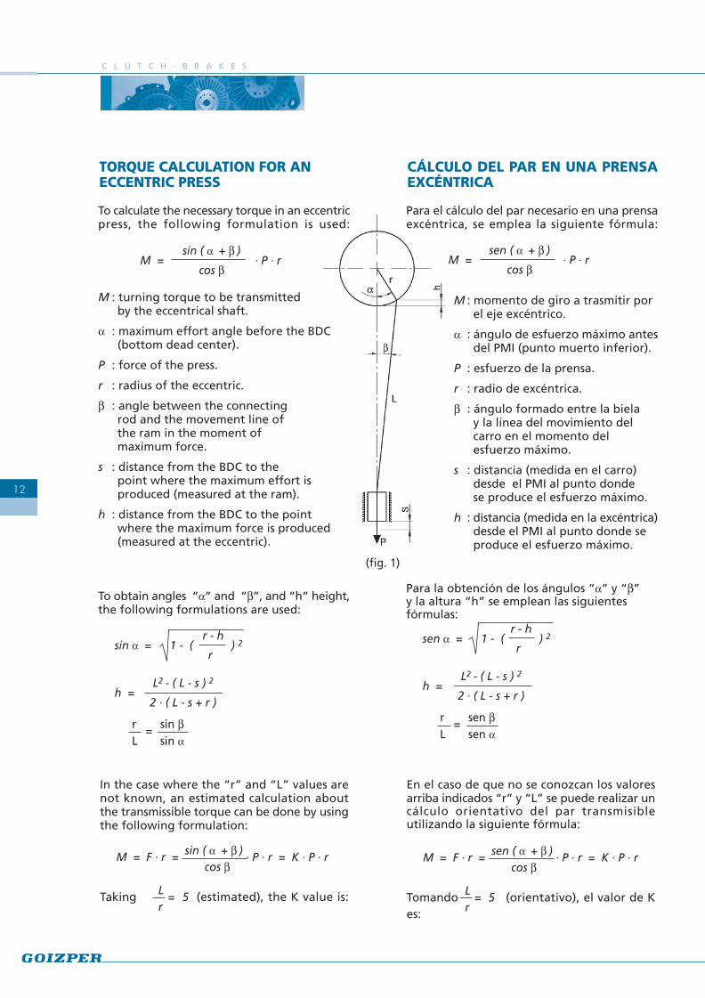
(fig. 1)
TORQUE CALCULATION FOR ANECCENTRIC PRESS
To calculate the necessary torque in an eccentricpress, the following formulation is used:
sin ( a + b )M = · P · r
cos b
M : turning torque to be transmittedby the eccentrical shaft.
a : maximum effort angle before the BDC(bottom dead center).
P : force of the press.
r : radius of the eccentric.
b : angle between the connectingrod and the movement line ofthe ram in the moment ofmaximum force.
s : distance from the BDC to thepoint where the maximum effort isproduced (measured at the ram).
h : distance from the BDC to the pointwhere the maximum force is produced(measured at the eccentric).
To obtain angles “a” and “b”, and “h” height,the following formulations are used:
r - hsin a = 1 - ( ) 2
r
L2 - ( L - s ) 2h =
2 · ( L - s + r )
r = sin bL sin a
CÁLCULO DEL PAR EN UNA PRENSAEXCÉNTRICA
Para el cálculo del par necesario en una prensaexcéntrica, se emplea la siguiente fórmula:
sen ( a + b )M = · P · r
cos b
M : momento de giro a trasmitir porel eje excéntrico.
a : ángulo de esfuerzo máximo antesdel PMI (punto muerto inferior).
P : esfuerzo de la prensa.
r : radio de excéntrica.
b : ángulo formado entre la bielay la línea del movimiento delcarro en el momento delesfuerzo máximo.
s : distancia (medida en el carro)desde el PMI al punto dondese produce el esfuerzo máximo.
h : distancia (medida en la excéntrica)desde el PMI al punto donde seproduce el esfuerzo máximo.
Para la obtención de los ángulos “a” y “b”y la altura “h” se emplean las siguientesfórmulas:
r - hsen a = 1 - ( ) 2
r
L2 - ( L - s ) 2h =
2 · ( L - s + r )
r = sen bL sen a
In the case where the “r” and “L” values arenot known, an estimated calculation aboutthe transmissible torque can be done by usingthe following formulation:
M = F · r = sin ( a + b ) · P · r = K · P · r cos b
Taking L = 5 (estimated), the K value is: r
En el caso de que no se conozcan los valoresarriba indicados “r” y “L” se puede realizar uncálculo orientativo del par transmisibleutilizando la siguiente fórmula:
M = F · r = sen ( a + b ) · P · r = K · P · r cos b
Tomando L = 5 (orientativo), el valor de Kes: r
F R E N O - E M B R A G U E S
13
For a = 30° the coefficient K = 0,587For a = 15° the coefficient K = 0,3For a = 40° the coefficient K = 0,74For shears K = 1
When the clutch is in a faster shaft:
Mred = Mi
Being i the transmission ratiobetween the clutch shaft andthe eccentric shaft.
Para a = 30° el coeficiente K = 0,587Para a = 15° el coeficiente K = 0,3Para a = 40° el coeficiente K = 0,74Para cizallas K = 1
Cuando el embrague está en un eje más rápido:
Mred = Mi
Siendo i la relación detransmisión entre el eje delembrague y el eje excéntrico
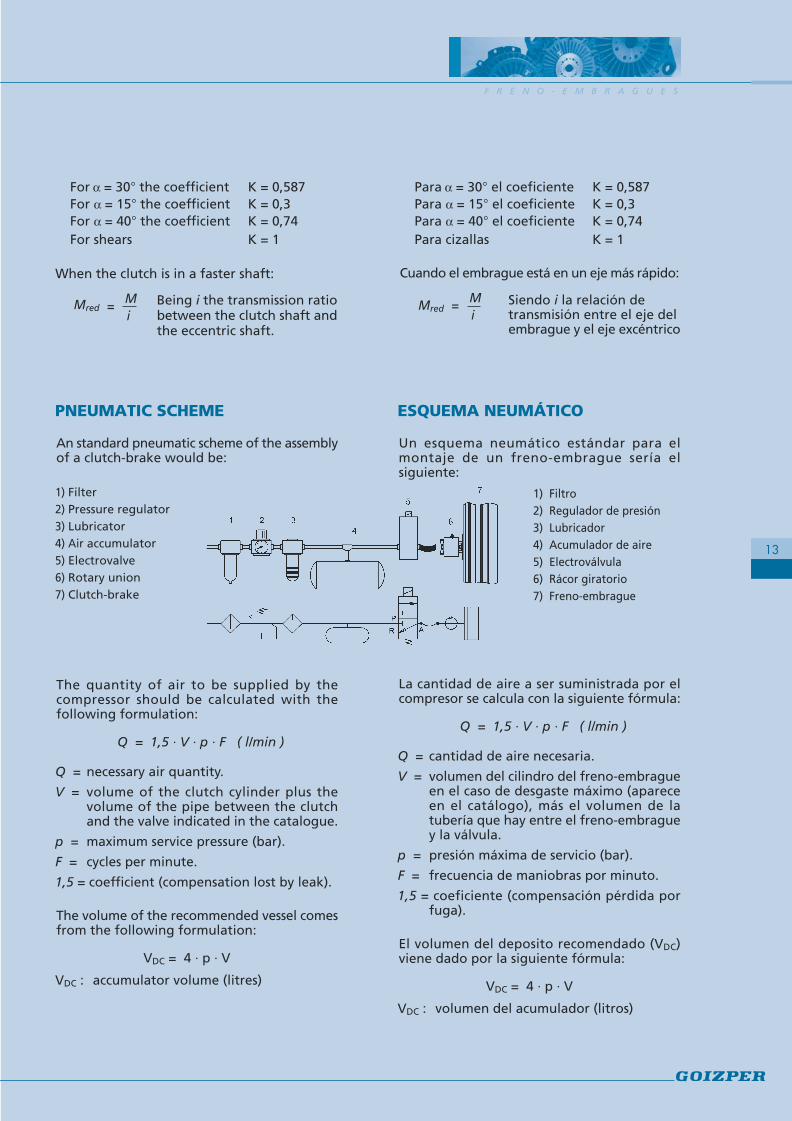
ESQUEMA NEUMÁTICO
Un esquema neumático estándar para elmontaje de un freno-embrague sería elsiguiente:
1) Filtro2) Regulador de presión3) Lubricador4) Acumulador de aire5) Electroválvula6) Rácor giratorio7) Freno-embrague
La cantidad de aire a ser suministrada por elcompresor se calcula con la siguiente fórmula:
Q = 1,5 · V · p · F ( l/min )
Q = cantidad de aire necesaria.
V = volumen del cilindro del freno-embragueen el caso de desgaste máximo (apareceen el catálogo), más el volumen de latubería que hay entre el freno-embraguey la válvula.
p = presión máxima de servicio (bar).
F = frecuencia de maniobras por minuto.
1,5 = coeficiente (compensación pérdida porfuga).
El volumen del deposito recomendado (VDC)viene dado por la siguiente fórmula:
VDC = 4 · p · V
VDC : volumen del acumulador (litros)
PNEUMATIC SCHEME
An standard pneumatic scheme of the assemblyof a clutch-brake would be:
1) Filter2) Pressure regulator3) Lubricator4) Air accumulator5) Electrovalve6) Rotary union7) Clutch-brake
The quantity of air to be supplied by thecompressor should be calculated with thefollowing formulation:
Q = 1,5 · V · p · F ( l/min )
Q = necessary air quantity.
V = volume of the clutch cylinder plus thevolume of the pipe between the clutchand the valve indicated in the catalogue.
p = maximum service pressure (bar).
F = cycles per minute.
1,5 = coefficient (compensation lost by leak).
The volume of the recommended vessel comesfrom the following formulation:
VDC = 4 · p · V
VDC : accumulator volume (litres)

P N E U M A T I C C L U T C H - B R A K E S
14
F R E N O - E M B R A G U E S N E U M Á T I C O S
15
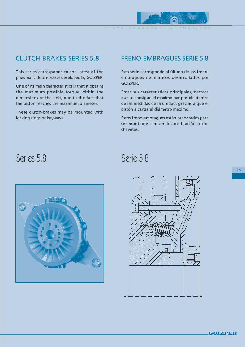
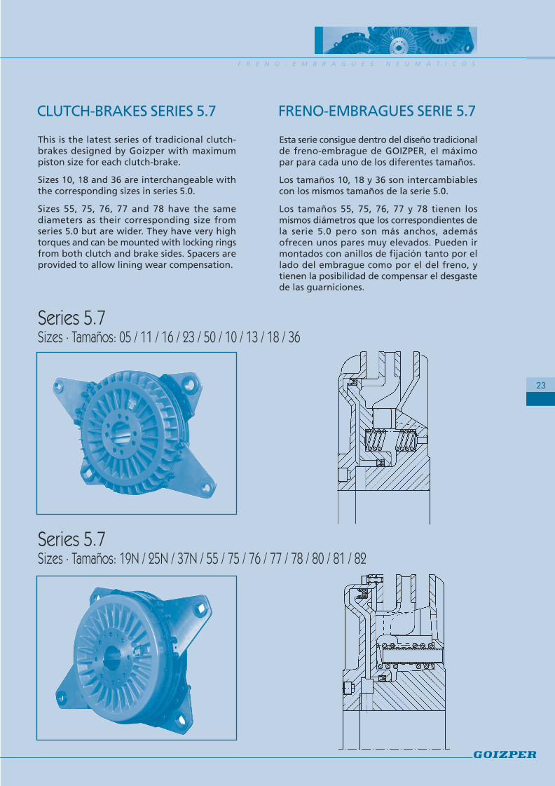
Esta serie corresponde al último de los freno-embragues neumáticos desarrollados porGOIZPER.
Entre sus características principales, destacaque se consigue el máximo par posible dentrode las medidas de la unidad, gracias a que elpistón alcanza el diámetro máximo.
Estos freno-embragues están preparados paraser montados con anillos de fijación o conchavetas.
CLUTCH-BRAKES SERIES 5.8 FRENO-EMBRAGUES SERIE 5.8
Series 5.8 Serie 5.8
This series corresponds to the latest of thepneumatic clutch-brakes developed by GOIZPER.
One of its main characteristics is that it obtainsthe maximum possible torque within thedimensions of the unit, due to the fact thatthe piston reaches the maximum diameter.
These clutch-brakes may be mounted withlocking rings or keyways.
P N E U M A T I C C L U T C H - B R A K E S
16
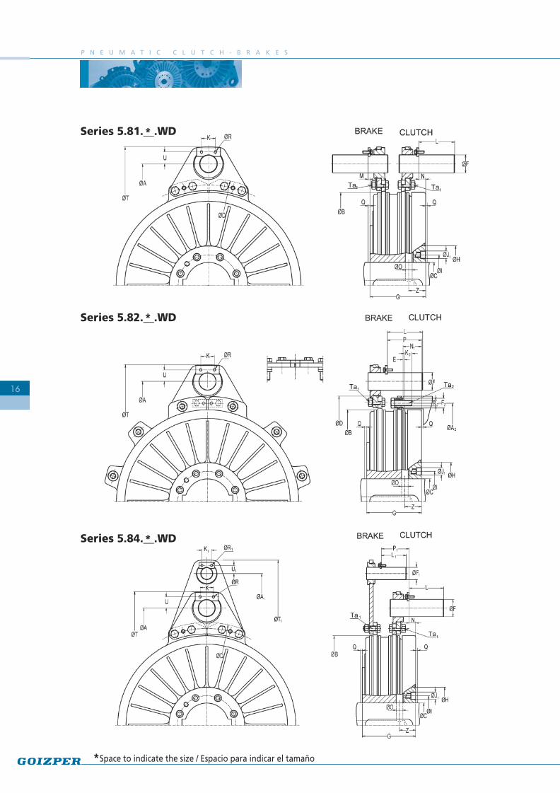
Series 5.81.__.WD
Series 5.82.__.WD
Series 5.84.__.WD
*
*
*
*Space to indicate the size / Espacio para indicar el tamaño

23 50 10 18 36 55 75 76 77 78 80480 940 2000 4000 7550 11900 15500 22900 32000 42800 56600345 665 1450 2850 5390 8500 11200 16300 22850 30500 38500
2750 2250 1750 1500 1250 1100 1000 850 750 700 6309.2 15.5 32 60 112 170 228 325 453 655 8209 15 30 58 106 163 220 313 437 615 774
9.2 15.5 32 60 112 170 228 325 453 655 8200.026 0.07 0.25 0.72 1.85 4.24 6.6 12.2 21.1 31.5 51.40.013 0.04 0.1 0.283 0.953 1.546 2.91 4.97 8.82 20 27.30.008 0.027 0.062 0.202 0.615 1.031 1.55 3.34 6.51 10.5 12.80.013 0.04 0.1 0.283 0.953 1.546 2.91 4.97 8.82 20 27.30.093 0.164 0.320 0.671 1.18 1.75 2.23 3.21 4.88 6.42 8.380.148 0.250 0.524 1.038 1.95 2.79 3.58 5.23 7.62 9.97 13.6250 315 390 495 610 695 770 880 970 1100 1180325 410 490 635 790 885 990 1135 1235 1450 1525205 255 325 408 500 584 640 725 810 890 965188 236 305 380 466 543 593 675 755 830 90528 35 45 55 70 80 90 100 115 115 13548 65 80 95 125 145 160 180 200 220 240226 275 347 435 535 620 680 775 865 950 10251.7 2 3 3 3 3 3 4 4 4 415 22 30 32 45 45 60 60 65 75 8015 15 22 30 32 32 45 45 60 65 6510 12 15 18 25 25 30 35 40 45 4566 75 92 112 140 160 175 195 220 240 26085 105 141 168 198 224 250 294 324 354 39060 79 99 118 153 176 194 221 246 270 3059.5 11 13.5 16.5 19 19 23 25 28 33 3320 25 25 25 35 35 45 45 45 60 6020 20 25 25 25 25 35 35 45 45 457.5 11 13 16 20 20 25 38 43 36 3630 45 60 65 90 90 120 120 130 150 16030 30 45 60 65 65 90 90 120 130 1303 4 4 5 5 5 5 5 5 20 15
7.5 8 10.5 13 17 22 24 26 28 17 2822 25.5 31.5 38 47 55 61 66 75 81 906 8 10 14 17 20 22 25 28 30 3538 40 54 69 87 102 110 125 136 141.5 15732 38.5 45 58 73 84 86 100 114 121.5 1323 4 4 5 5 5 5 5 5 5 5
4.5 5.5 5.5 5.5 6.5 6.5 8.5 8.5 8.5 10.5 10.54.5 4.5 5.5 5.5 5.5 5.5 6.5 6.5 8.5 8.5 8.5M5 M6 M8 M10 M14 M14 M16 M20 M24 M24 M24284 360 446 565 695 785 880 1000 1110 1260 13340359 444 535 691 860 955 1075 1220 1345 1595 167011 16 20 21 29.5 29.5 41 41 43.5 52.5 5511 11 16 20 21 21 29.5 29.5 41 43.5 43.517 22 28 36 42.5 51 55 62.5 71 78 866,6 11 27,5 54 95 148 230 230 450 780 7806 10 25 49 135 135 210 410 710 710 710
SizeClutch torqueBrake torquePressure barMax speed min-1
5.81 WDWeight 5.82 WD Kg
5.84 WDJ. int. Kg m2
5.81 WDJ. ext. 5.82 WD Kg m2
5.84 WDNew volum.Max. wear Volum.
Ø AØ A1Ø A2Ø B
Ø C MinMax
Ø DE
Ø FØ F1Ø F2 12 x 30°
GØ HØ IØ J1
KK1K2LL1MNN1
Ø O 2 a 180°PP1Q(*)
Ø RØ R1Ø R2 12 x 30°Ø TØ T1Ø UØ U1
ZTa1
Ta2
F R E N O - E M B R A G U E S N E U M Á T I C O S
17
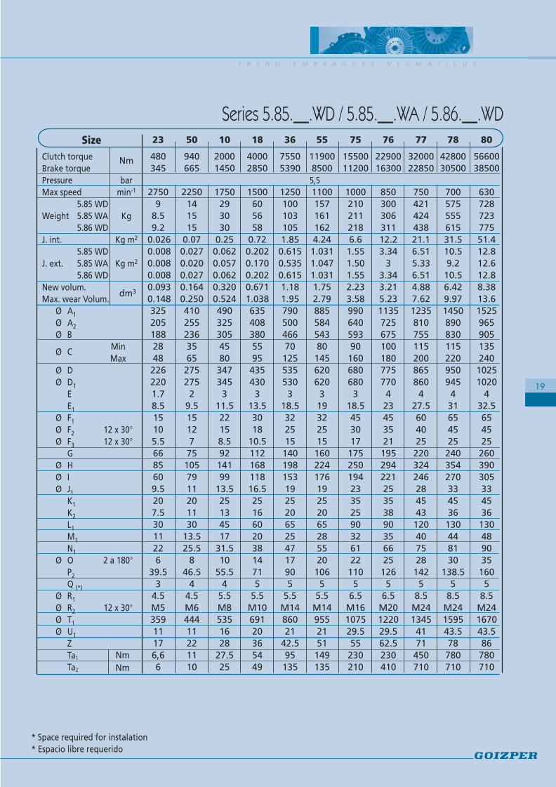
Series 5.81.__.WD / 5.82.__.WD / 5.84.__.WD
Nm
dm3
5,5
* Space required for instalation * Espacio libre requerido
NmNm

P N E U M A T I C C L U T C H - B R A K E S
18
Series 5.85.__.WD
Series 5.85.__.WA
Series 5.86.__.WD
*
*
*
*Space to indicate the size / Espacio para indicar el tamaño
F R E N O - E M B R A G U E S N E U M Á T I C O S
19
23 50 10 18 36 55 75 76 77 78 80
480 940 2000 4000 7550 11900 15500 22900 32000 42800 56600345 665 1450 2850 5390 8500 11200 16300 22850 30500 38500
2750 2250 1750 1500 1250 1100 1000 850 750 700 6309 14 29 60 100 157 210 300 421 575 728
8.5 15 30 56 103 161 211 306 424 555 7239.2 15 30 58 105 162 218 311 438 615 775
0.026 0.07 0.25 0.72 1.85 4.24 6.6 12.2 21.1 31.5 51.40.008 0.027 0.062 0.202 0.615 1.031 1.55 3.34 6.51 10.5 12.80.008 0.020 0.057 0.170 0.535 1.047 1.50 3 5.33 9.2 12.60.008 0.027 0.062 0.202 0.615 1.031 1.55 3.34 6.51 10.5 12.80.093 0.164 0.320 0.671 1.18 1.75 2.23 3.21 4.88 6.42 8.380.148 0.250 0.524 1.038 1.95 2.79 3.58 5.23 7.62 9.97 13.6325 410 490 635 790 885 990 1135 1235 1450 1525205 255 325 408 500 584 640 725 810 890 965188 236 305 380 466 543 593 675 755 830 90528 35 45 55 70 80 90 100 115 115 13548 65 80 95 125 145 160 180 200 220 240226 275 347 435 535 620 680 775 865 950 1025220 275 345 430 530 620 680 770 860 945 10201.7 2 3 3 3 3 3 4 4 4 48.5 9.5 11.5 13.5 18.5 19 18.5 23 27.5 31 32.515 15 22 30 32 32 45 45 60 65 6510 12 15 18 25 25 30 35 40 45 455.5 7 8.5 10.5 15 15 17 21 25 25 2566 75 92 112 140 160 175 195 220 240 26085 105 141 168 198 224 250 294 324 354 39060 79 99 118 153 176 194 221 246 270 3059.5 11 13.5 16.5 19 19 23 25 28 33 3320 20 25 25 25 25 35 35 45 45 457.5 11 13 16 20 20 25 38 43 36 3630 30 45 60 65 65 90 90 120 130 13011 13.5 17 20 25 28 32 35 40 44 4822 25.5 31.5 38 47 55 61 66 75 81 906 8 10 14 17 20 22 25 28 30 35
39.5 46.5 55.5 71 90 106 110 126 142 138.5 1603 4 4 5 5 5 5 5 5 5 5
4.5 4.5 5.5 5.5 5.5 5.5 6.5 6.5 8.5 8.5 8.5M5 M6 M8 M10 M14 M14 M16 M20 M24 M24 M24359 444 535 691 860 955 1075 1220 1345 1595 167011 11 16 20 21 21 29.5 29.5 41 43.5 43.517 22 28 36 42.5 51 55 62.5 71 78 866,6 11 27.5 54 95 149 230 230 450 780 7806 10 25 49 135 135 210 410 710 710 710
Series 5.85.__.WD / 5.85.__.WA / 5.86.__.WD
Nm
dm3
5,5
* Space required for instalation* Espacio libre requerido
SizeClutch torqueBrake torquePressure barMax speed min-1
5.85 WDWeight 5.85 WA Kg
5.86 WDJ. int. Kg m2
5.85 WDJ. ext. 5.85 WA Kg m2
5.86 WDNew volum.Max. wear Volum.
Ø A1Ø A2Ø B
Ø C MinMax
Ø DØ D1
EE1
Ø F1Ø F2 12 x 30°Ø F3 12 x 30°
GØ HØ IØ J1
K1K2L1M1N1
Ø O 2 a 180°P2Q (*)
Ø R1Ø R2 12 x 30°Ø T1Ø U1
ZTa1
Ta2
NmNm
P N E U M A T I C C L U T C H - B R A K E S
20
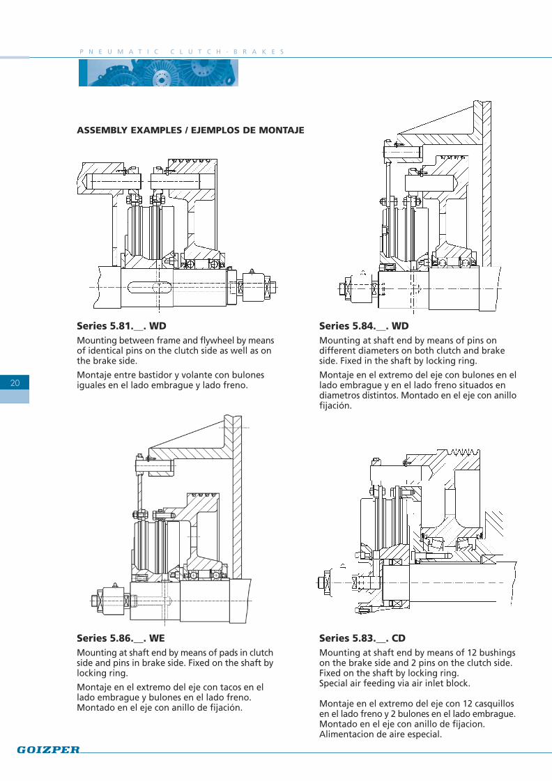
ASSEMBLY EXAMPLES / EJEMPLOS DE MONTAJE
Series 5.81.__. WDMounting between frame and flywheel by meansof identical pins on the clutch side as well as onthe brake side.
Montaje entre bastidor y volante con bulonesiguales en el lado embrague y lado freno.
Series 5.84.__. WDMounting at shaft end by means of pins ondifferent diameters on both clutch and brakeside. Fixed in the shaft by locking ring.
Montaje en el extremo del eje con bulones en ellado embrague y en el lado freno situados endiametros distintos. Montado en el eje con anillofijación.
Series 5.83.__. CDMounting at shaft end by means of 12 bushingson the brake side and 2 pins on the clutch side.Fixed on the shaft by locking ring.Special air feeding via air inlet block.
Montaje en el extremo del eje con 12 casquillosen el lado freno y 2 bulones en el lado embrague.Montado en el eje con anillo de fijacion.Alimentacion de aire especial.
Series 5.86.__. WEMounting at shaft end by means of pads in clutchside and pins in brake side. Fixed on the shaft bylocking ring.
Montaje en el extremo del eje con tacos en ellado embrague y bulones en el lado freno.Montado en el eje con anillo de fijación.
F R E N O - E M B R A G U E S N E U M Á T I C O S
21
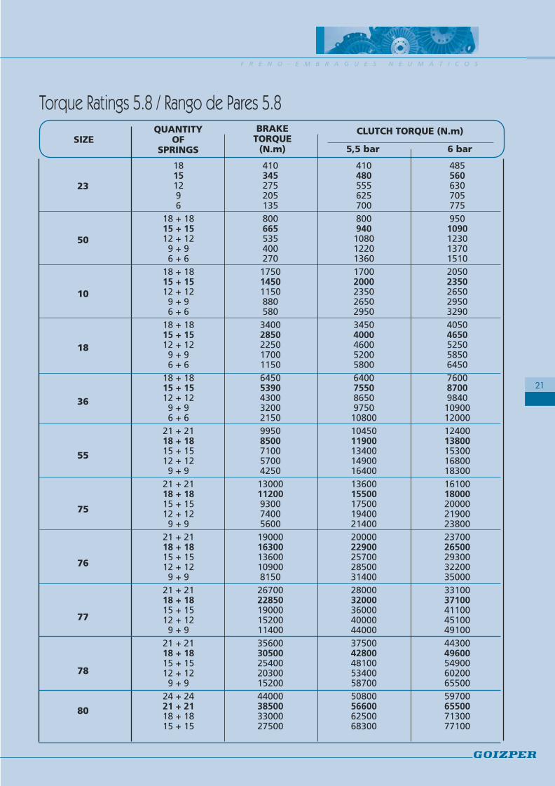
QUANTITYOF
SPRINGS
Torque Ratings 5.8 / Rango de Pares 5.8
SIZEBRAKE
TORQUE(N.m)
CLUTCH TORQUE (N.m)
23
50
10
18
36
55
75
76
77
78
80
18 410 410 48515 345 480 56012 275 555 6309 205 625 7056 135 700 775
18 + 18 800 800 95015 + 15 665 940 109012 + 12 535 1080 12309 + 9 400 1220 13706 + 6 270 1360 1510
18 + 18 1750 1700 205015 + 15 1450 2000 235012 + 12 1150 2350 26509 + 9 880 2650 29506 + 6 580 2950 3290
18 + 18 3400 3450 405015 + 15 2850 4000 465012 + 12 2250 4600 52509 + 9 1700 5200 58506 + 6 1150 5800 6450
18 + 18 6450 6400 760015 + 15 5390 7550 870012 + 12 4300 8650 98409 + 9 3200 9750 109006 + 6 2150 10800 12000
21 + 21 9950 10450 1240018 + 18 8500 11900 1380015 + 15 7100 13400 1530012 + 12 5700 14900 168009 + 9 4250 16400 18300
21 + 21 13000 13600 1610018 + 18 11200 15500 1800015 + 15 9300 17500 2000012 + 12 7400 19400 219009 + 9 5600 21400 23800
21 + 21 19000 20000 2370018 + 18 16300 22900 2650015 + 15 13600 25700 2930012 + 12 10900 28500 322009 + 9 8150 31400 35000
21 + 21 26700 28000 3310018 + 18 22850 32000 3710015 + 15 19000 36000 4110012 + 12 15200 40000 451009 + 9 11400 44000 49100
21 + 21 35600 37500 4430018 + 18 30500 42800 4960015 + 15 25400 48100 5490012 + 12 20300 53400 602009 + 9 15200 58700 65500
24 + 24 44000 50800 5970021 + 21 38500 56600 6550018 + 18 33000 62500 7130015 + 15 27500 68300 77100
5,5 bar 6 bar

P N E U M A T I C C L U T C H - B R A K E S
22
F R E N O - E M B R A G U E S N E U M Á T I C O S
23
Esta serie consigue dentro del diseño tradicionalde freno-embrague de GOIZPER, el máximopar para cada uno de los diferentes tamaños.
Los tamaños 10, 18 y 36 son intercambiablescon los mismos tamaños de la serie 5.0.
Los tamaños 55, 75, 76, 77 y 78 tienen losmismos diámetros que los correspondientes dela serie 5.0 pero son más anchos, ademásofrecen unos pares muy elevados. Pueden irmontados con anillos de fijación tanto por ellado del embrague como por el del freno, ytienen la posibilidad de compensar el desgastede las guarniciones.
This is the latest series of tradicional clutch-brakes designed by Goizper with maximumpiston size for each clutch-brake.
Sizes 10, 18 and 36 are interchangeable withthe corresponding sizes in series 5.0.
Sizes 55, 75, 76, 77 and 78 have the samediameters as their corresponding size fromseries 5.0 but are wider. They have very hightorques and can be mounted with locking ringsfrom both clutch and brake sides. Spacers areprovided to allow lining wear compensation.
CLUTCH-BRAKES SERIES 5.7 FRENO-EMBRAGUES SERIE 5.7
Series 5.7Sizes · Tamaños: 19N / 25N / 37N / 55 / 75 / 76 / 77 / 78 / 80 / 81 / 82
Series 5.7Sizes · Tamaños: 05 / 11 / 16 / 23 / 50 / 10 / 13 / 18 / 36
P N E U M A T I C C L U T C H - B R A K E S
24
Series 5.71.__.WD
Series 5.72.__.WD
Series 5.74.__.WD*
*Space to indicate the size / Espacio para indicar el tamaño
*
*

1117575
32007
6,57
0,0130,0050,0030,0050,0350,075220
-1731581935192212-
10 (6)506565479,516-822-186513-
4,5-
M5(6)385,8242
-10,5
-M547166,66
3657104060
1200868586
1,410,7680,530,7680,741,26610790500466501105353403025125190180133193525208060415171458746,55,5
M1475
13,56958552720
M12226,5
3195135
1827601960
14504745470,5
0,2740,2020,2740,430,744956354083804590435330221810015314510913,52525166045315
14,51239535,55,5
M1070
10,55606802016M8182265449
19N34302495
1450575557
0,650,2740,2020,2740,580,984956354083804590435330221811217216012913,525251660451912161339525,55,5
M1070
10,55606802016M8205275449
23265185
27009
8,59
0,0220,0320,0080,0320,0720,1225032520518825352262141410587070479,52020828280109618274,54,5M5385,82803611111M647176,66
50695490
2250171617
0,050,0430,0270,0430,1450,2733154102552363052275222141266979065
10,525201245280
8,511624395,54,5M6466,53604461611M611318,51110
1314651030
1750272627
0,1730,1140,0620,1140,2760,462390490325305356534732214158212513081,513,525201445282,510141027495,54,5M8569,54355271611M814623
27,525
1014651030
1750262526
0,1730,1140,0620,1140,2760,462390490325305356534732214158212513081,513,525201345281
12,5141027
46,55,54,5M8569,54355271611M814621
27,525
056528
35003,53
3,50,0040,0030,0020,0030,020,045180
-1351201424151212-
9 (6)42606035916-818-26546-
4,5-
M4(6)306
203-
10,5-
M535126,62,9
25N47853410
1300747374
1,060,560,3820,560,781,3655071045042045954823323022125192166142172525206560257181448545,55,5
M1275
13,56227752120
M10240305486
37N67204780
12001071061071,720,8470,6090,8470,981,7661079050046650110535340302514021019015616,53525238060
22,510,5221658
66,56,55,5
M1475
13,56958552720
M122683395135
5595008000
10001491431493,811,351,041,351,452,56958855845436415062034030251602452501922035252480602513251863
80,56,55,5
M1484177809502720
M1629037,5148135
751340010000
9001971851975,582,141,552,141,763,12770990640593901656905454030185270270214203535289080
39,512,5272065816,56,5
M169617870107529,527
M1632944230210
761910015800
80027326427310,54,573,344,572,845,28801135725675100180775555453520531029024026453538110903818292180
98,58,56,5
M2011020
1000122038,529,5M1637347230410
772930020500
750443432443
19,277,516,517,514,458,26970123581075512518086555545402303203202562645354311090
48,512,5342395
107,58,56,5
M2412021
1090133538,529,5M1629055450710
783900027600
700655615655
30,6520
10,7205,210,211001450890830125200950107565452483453502852660454515013034,526,5382599
120,510,58,5
M2413824
1260159552,543,5M1832060780710
16205125
32006,56
6,50,0140,0090,0050,0090,040,062303051821661935198214141046751215192020825250,55,58418
26,54,54,5M5385,82623371111M667156,66
805000036000
630765723768
45,5526,613,126,66,911,7118015259659051402201025107565452603953703192660454515013038,522,54232
99,5124,510,58,5
M2413824
1340167052,543,5M1850068780710
817000050000
56095391696380,633,620
33,59,316,413001645108010151502401145107565502954504503663060454615013057,516,54632
120,5134,510,58,5
M2713824
1460179052,543,5M20570767801050
829800071500
50013601280134613929,217,329,212,521,914651855121511401703001276109075553304904904174260605518015059,519,55235
142,515810,510,5M3013824
1650201560
52,5M2462885
15001450
F R E N O - E M B R A G U E S N E U M Á T I C O S
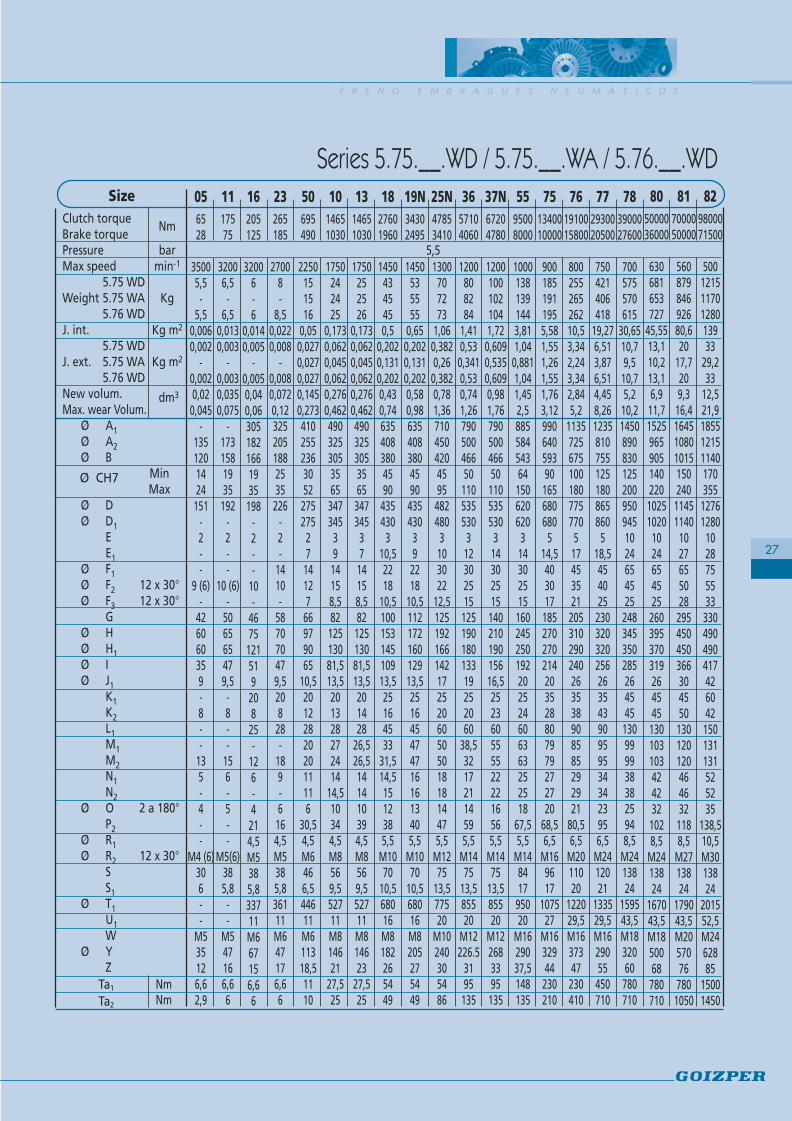
Series 5.71.__.WD / 5.72.__.WD / 5.74.__.WD Size
Clutch torqueBrake torquePressure barMax speed min-1
5.71 WDWeight 5.72 WD Kg
5.74 WDJ. int. Kg m2
5.71 WDJ. ext. 5.72 WD Kg m2
5.74 WDNew volum.Max. wear Volum.
Ø AØ A1Ø A2Ø B Min
MaxØ D
EØ FØ F1Ø F2 12 x 30°
GØ HØ H1Ø IØ J1
KK1K2LL1MNN1
Ø O 2 a 180°PP1
Ø RØ R1Ø R2 12 x 30°
SS1
Ø TØ T1
UU1W
Ø YZ
Ta1
Ta2
Nm
dm3
Ø CH7
5,5
25
NmNm

P N E U M A T I C C L U T C H - B R A K E S
26
Series 5.75.__.WA
Series 5.75.__.WD
Series 5.76.__.WD
*Space to indicate the size / Espacio para indicar el tamaño
*
*
*
SizeClutch torqueBrake torquePressure barMax speed min-1
5.75 WDWeight 5.75 WA Kg
5.76 WDJ. int. Kg m2
5.75 WDJ. ext. 5.75 WA Kg m2
5.76 WDNew volum.Max. wear Volum.
Ø A1Ø A2Ø B Min
MaxØ DØ D1
EE1
Ø F1Ø F2 12 x 30°Ø F3 12 x 30°
GØ HØ H1Ø IØ J1
K1K2L1M1M2N1N2
Ø O 2 a 180°P2
Ø R1Ø R2 12 x 30°
SS1
Ø T1U1W
Ø YZ
Ta1
Ta2
F R E N O - E M B R A G U E S N E U M Á T I C O S
27
Series 5.75.__.WD / 5.75.__.WA / 5.76.__.WD056528
35005,5-
5,50,0060,002
-0,0020,020,045
-1351201424151
-2--
9 (6)-
426060359-8--
135-4--
M4 (6)306--
M535126,62,9
1117575
32006,5-
6,50,0130,003
-0,0030,0350,075
-1731581935192
-2--
10 (6)-
506565479,5-8--
156-5--
M5(6)385,8--
M547166,66
3657104060
1200808284
1,410,530,3410,530,741,267905004665011053553031230251512519018013319252060
38,532172114595,5
M1475
13,585520
M12226.5
3195135
1827601960
14504345450,5
0,2020,1310,2020,430,7463540838045904354303
10,52218
10,510015314510913,525164533
31,514,51512385,5
M1070
10,568016M8182265449
19N34302495
1450535555
0,650,2020,1310,2020,580,986354083804590435430392218
10,511217216012913,52516454747161613405,5
M1070
10,568016M8205275449
23265185
27008-
8,50,0220,008
-0,0080,0720,123252051882535226
-2-
1410-
587070479,520828-
189-6164,5M5385,836111M647176,66
50695490
2250151516
0,050,0270,0270,0270,1450,2734102552363052275275271412766979065
10,5201228202011116
30,54,5M6466,544611M611318,51110
1314651030
1750252526
0,1730,0620,0450,0620,2760,46249032530535653473453714158,58212513081,513,5201428
26,526,5141410394,5M8569,552711M814623
27,525
1014651030
1750242425
0,1730,0620,0450,0620,2760,46249032530535653473453914158,58212513081,513,5201328272414
14,510344,5M8569,552711M814621
27,525
25N47853410
1300707273
1,060,3820,260,3820,781,3671045042045954824803103022
12,5125192166142172520605050181814475,5
M1275
13,577520
M10240305486
37N67204780
12001001021041,720,6090,5350,6090,981,767905004665011053553031430251514021019015616,52523605555222216565,5
M1475
13,585520
M122683395135
5595008000
10001381391443,811,040,8811,041,452,588558454364150620620314302515160245250192202524606363252518
67,55,5
M14841795020
M1629037,5148135
751340010000
9001851911955,581,551,261,551,763,12990640593901656806805
14,5403017185270270214203528807979272720
68,56,5
M169617
107527
M1632944230210
761910015800
80025526526210,53,342,243,342,845,2
1135725675100180775770517453521205310290240263538908585292921
80,56,5
M2011020
122029,5M1637347230410
772930020500
750421406418
19,276,513,876,514,458,2612358107551251808658605
18,5454025230320320256263543909595343423956,5
M2412021
133529,5M1629055450710
783900027600
700575570615
30,6510,79,510,75,210,2145089083012520095094510246545252483453502852645451309999383825948,5
M2413824
159543,5M1832060780710
Nm
dm3
Ø CH7
5,5
805000036000
630681653727
45,5513,110,213,16,911,715259659051402201025102010246545252603953703192645451301031034242321028,5
M2413824
167043,5M1850068780710
16205125
32006-6
0,0140,005
-0,0050,040,063051821661935198
-2--
10-
467512151920825-
126-4214,5M5385,833711M667156,66
817000050000
56087984692680,620
17,7209,316,41645108010151502401145114010276550282954504503663045501301201204646321188,5
M2713824
179043,5M20570767801050
829800071500
50012151170128013933
29,233
12,521,9185512151140170355127612801028755533330490490417426042150131131525235
138,510,5M3013824
201552,5M2462885
15001450
NmNm
P N E U M A T I C C L U T C H - B R A K E S
28
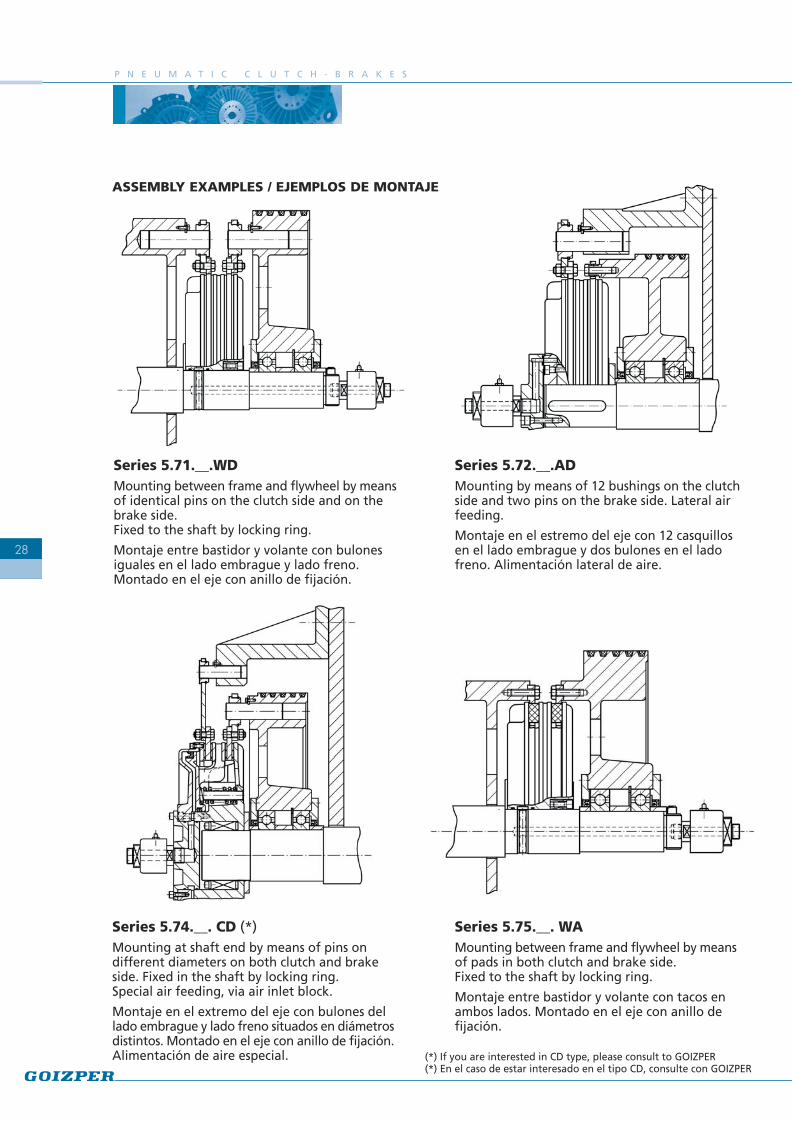
Series 5.71.__.WDMounting between frame and flywheel by meansof identical pins on the clutch side and on thebrake side.Fixed to the shaft by locking ring.
Montaje entre bastidor y volante con bulonesiguales en el lado embrague y lado freno.Montado en el eje con anillo de fijación.
Series 5.72.__.ADMounting by means of 12 bushings on the clutchside and two pins on the brake side. Lateral airfeeding.
Montaje en el estremo del eje con 12 casquillosen el lado embrague y dos bulones en el ladofreno. Alimentación lateral de aire.
Series 5.75.__. WAMounting between frame and flywheel by meansof pads in both clutch and brake side.Fixed to the shaft by locking ring.
Montaje entre bastidor y volante con tacos enambos lados. Montado en el eje con anillo defijación.
Series 5.74.__. CD (*)Mounting at shaft end by means of pins ondifferent diameters on both clutch and brakeside. Fixed in the shaft by locking ring.Special air feeding, via air inlet block.
Montaje en el extremo del eje con bulones dellado embrague y lado freno situados en diámetrosdistintos. Montado en el eje con anillo de fijación.Alimentación de aire especial. (*) If you are interested in CD type, please consult to GOIZPER
(*) En el caso de estar interesado en el tipo CD, consulte con GOIZPER
ASSEMBLY EXAMPLES / EJEMPLOS DE MONTAJE

F R E N O - E M B R A G U E S N E U M Á T I C O S
29
QUANTITYOF
SPRINGSSIZE
BRAKETORQUE
(N.m)
CLUTCH TORQUE (N.m)
511
16
23
50
10
13
18
19N
25N
36
37N
55
75
76
77
78
80
81
82
8 28 65 7510 75 175 20016 125 205 23514 110 220 25012 90 240 2708 62 270 30012 185 265 3109 135 315 3606 92 365 405
10 + 10 490 695 80510 + 5 385 805 91510+ 0 275 920 10305 + 5 245 950 1060
12 + 12 1030 1465 169512 + 6 860 1645 187512 + 0 690 1820 20506 + 6 515 1995 2225
12 + 12 1030 1465 169512 + 6 860 1645 187512 + 0 690 1820 20506 + 6 515 1995 2225
12 + 12 1960 2760 319012 + 8 1690 3040 34809 + 6 1265 3480 39106 + 6 980 3770 4200
16 2495 3430 398014 2180 3755 430012 1870 4080 46258 1245 4730 527516 3410 4785 554014 2985 5225 598012 2555 5665 64208 1700 6545 720018 4060 5710 662015 3380 6410 731012 2710 7110 80109 2030 7810 871016 4780 6720 778514 4180 7340 840012 3585 7965 90258 2380 9200 1027016 8000 9500 1110014 7000 10500 1220012 6000 11600 132008 4000 13600 1530016 10000 13400 1560014 8700 14700 1690012 7500 16000 182008 5000 18600 20700
16 + 16 15800 19100 2230012 + 16 13500 21400 2470010 + 10 9900 25300 285008 + 8 7900 27300 30500
18 20500 29300 3400015 17100 32900 3750012 13700 36500 411009 10250 40000 44700
20 + 20 27600 39000 4520016 + 20 23600 43200 4940010 + 20 17500 49500 5560010 + 10 13800 53400 5950024 + 24 36000 50000 5800020 + 20 30000 56500 6450016 + 16 24000 63000 7100012 + 12 18000 69000 7750024 + 24 50000 70000 8100020 + 20 41000 79000 9000016 + 16 33000 87000 9900012 + 12 25000 96000 10700024 + 24 71500 98000 11350020 + 20 59500 110500 12600016 + 16 47500 122500 13850012 + 12 35500 135000 151000
5,5 bar 6 bar
Torque Ratings 5.7 / Rango de Pares 5.7

P N E U M A T I C C L U T C H - B R A K E S
30
F R E N O - E M B R A G U E S N E U M Á T I C O S
31
Los freno-embragues de la serie 5.0 son laúltima versión de nuestro tradicional diseñode freno embragues ensamblados por tirantes,los cuales atan ambas tapas para evitardeformaciones y roturas por fatiga.
Otra de sus características es que la tapa ladofreno es de aluminio con lo que se consigueuna baja inercia.
CLUTCH-BRAKES SERIES 5.0 FRENO-EMBRAGUES SERIE 5.0
Series 5.0 Serie 5.0
Series 5.0 is the latest version of our traditionaldesign of clutch-brakes assembled by pins thattighten both covers for avoiding theirdeformation and breakage due to stress.
The brake side cover is manufactured inaluminium, obtaining a low inertia.
P N E U M A T I C C L U T C H - B R A K E S
32
Series 5.01.__.WD
Series 5.02.__.WD
Series 5.04.__.WD*
*Space to indicate the size / Espacio para indicar el tamaño
*
*

F R E N O - E M B R A G U E S N E U M Á T I C O S
33
55700042505,5
10001221171222,731,3541,0441,3541,151 ,969588558454260114620540302514520620013616,5352530806050415191661866,55,5
M1484177809502720
M1216036,5148135
75102005900
9001751631754,552,1441,5552,1441,472,4477099064059960125680545403016022522015016,53535329080608
17,5201658846,56,5
M169617870107529,527
M1217041230210
76143008700
8002382292387,374,573,3424,572,253,86880113572567575145775555453518526526516818,545353611090708202220831038,56,5
M2011020
1000122038,529,5M1421048230410
771920011500
760324312324
13,257,516,517,512,834,98970123581075590160865555454020327627618622,5453540110908014202520941158,56,5
M2412021
1090133538,529,5M1622053450710
783080017700
600537515537
29,8816,7812,616,785,378,7
114014509458851151801000
5655542255
300(330)3002122845454813011090202033281141478,58,5
M2413824
1285157043,538,5M1825067450710
60690430
2300161516
0,080,0430,0270,0430,1360,255345440283265325230522214127210511066
10,525201445282511012827395,54,5M6466,53904751611M866201110
SizeClutch torqueBrake torquePressure BarMax speed min-1
5.01 WDWeight 5.02 WD Kg
5.04 WDInt.
J 5.01 WDExt. 5.02 WD Kg m2
5.04 WDNew volum.Max. wear Volum.
Ø AØ A1Ø A2Ø B Min
MaxØ D
EØ FØ F1Ø F2
GØ HØ H1Ø IØ J1
KK1K2LL1L2MNN1
Ø O 2 x 180°PP1
Ø RØ R1Ø R2 12 x 30°
SS1TT1UU1W
Ø YZTa1
Ta2
Nm
dm3
Ø CH7
101100585
1750242324
0,190,1140,0620,1140,230,385390490325305356534732214158212513082
10,52520174528301
12,5141027
46,55,54,5M8569,54355271611M88221
27,525
1821001370
1450434143
0,460,2740,2020,2740,4820,7924956354083804580435330221810014514595
13,5252519604535315
14,51239535,55,5
M1070
10,55606802016M8115265449
3645002930
1200797779
1,230,7680,530,7680,7971,3761079050046650108535340302512519018012313,5352525806045415171458746,55,5
M1475
13,56958552720
M101453195135
794510027800
450850
--
6232--
7,311
1300-
108010001402201145
-75--
2953763762903260--
150--
57,516,5
-32--
10,5----
1460-
51---
76780
-
Series 5.01.__.WD / 5.02.__.WD / 5.04.__.WD
NmNm
P N E U M A T I C C L U T C H - B R A K E S
34
Series 5.05.__.WD
Series 5.05.__.WA
Series 5.06.__.WD*
*Space to indicate the size / Espacio para indicar el tamaño
*
*

F R E N O - E M B R A G U E S N E U M Á T I C O S
35
55700042505,5
10001111121172,731,0440,8811,0441,151,98855845426011462062051630251514520620013616,525306050
45,54119
24,516715,5
M14841795020
M1216036,5148135
75102005900
9001531591634,551,5551,2611,5551,472,44990640599601256806805
16,540301716022522015016,5353280605750202616
66,56,5
M169617
107527
M1217041230210
76143008700
8002202302297,373,3422,243,3422,253,8611357256757514577077551745352118526526516818,5353690705950223120836,5
M2011020
122029,5M1421048230410
771920011500
760301292312
13,256,5133,876,5132,834,981235810755901608608655
18,545402520327627618622,5354090806657253420956,5
M2412021
133529,5M1622053450710
783080017700
600494482515
29,8812,68,4612,65,378,7
14509458851151809951000
524554225255
300(330)30021228454811090
83,57333
42,5281278,5
M2413824
157038,5M1825067450710
60690430
230014-
150,080,027
-0,0270,1360,2554402832653252-
3052-
1412-
7210511066
10,520142825-
2111-8294,5M6466,547511M866201110
SizeClutch torqueBrake torquePressure barMax speed min-1
5.05 WDWeight 5.05 WA Kg
5.06 WDInt.
J 5.05 WDExt. 5.05 WA Kg m2
5.06 WDNew volum.Max. wear Volum.
Ø A1Ø A2Ø B Min
MaxØ D1Ø D
EE1
Ø F1Ø F2Ø F3 12 x 30°
GØ HØ H1Ø IØ J1
K1K2L1L2M1M2N1N2
Ø O 2 x 180°P2
Ø R1Ø R2 12 x 30°
SS1T1U1W
Ø YZTa1
Ta2
Nm
dm3
Ø CH7
101100585
1750222223
0,190,0620,0450,0620,230,38549032530535653453473914158,58212513082
10,520172830272412
14,510344,5M8569,552711M88221
27,525
1821001370
1450394141
0,460,2020,1310,2020,4820,79263540838045804304353
10,52218
10,510014514595
13,52519453533
31,514,51512385,5
M1070
10,568016M8115265449
3645002930
1200737577
1,230,530,3410,530,7971,377905004665010853053531230251512519018012313,525256045
38,532172114595,5
M1475
13,585520
M101453195135
794510027800
450850
--
6232--
7,311-
10801000140220
-1145
-----
29537637629032--------
32---------
76780
-
Series 5.05.__.WD / 5.05.__.WA / 5.06.__.WD
NmNm

P N E U M A T I C C L U T C H - B R A K E S
36
Series 5.01.__.WDMounting between frame and flywheel by meansof identical pins in both clutch and brake side.
Montaje entre bastidor y volante con bulonesiguales en el lado embrague y lado freno.
Series 5.02.__.ADMounting at shaft end by means of 12 bushingson the clutch side and two pins on the brake side.Lateral air feeding.
Montaje entre bastidor y volante con 12 casquillosen el lado embrague y dos bulones en el ladofreno. Alimentación lateral de aire
Series 5.05.__.WAMounting between frame and flywheel by meansof pads in both clutch and brake side.Fixed in the shaft by locking ring.
Montaje entre bastidor y volante con tacos enambos lados. Montado en el eje con anillo defijación.
Series 5.04.__.WDMounting at shaft end by means of pins ondifferent diameters on both clutch and brakeside.
Montaje en extremo de eje con bulones del ladoembrague y lado freno situados en diámetrosdistintos.
ASSEMBLY EXAMPLES / EJEMPLOS DE MONTAJE

F R E N O - E M B R A G U E S N E U M Á T I C O S
37
QUANTITYOF
SPRINGSSIZE
BRAKETORQUE
(N.m)
CLUTCH TORQUE (N.m)
60
10
18
36
55
75
76
77
78
79
12 430 690 8009 320 800 9006 215 900 1000
18 585 1100 120015 485 1200 130012 390 1300 14009 290 1400 1500
16 1370 2100 240012 1025 2400 280010 855 2600 29008 685 2800 3100
18 2930 4500 520015 2445 5000 570012 1955 5500 62008 1465 6000 6700
18 4250 7000 800015 3550 7700 870012 2850 8400 95009 2125 9200 10200
24 5900 10200 1170020 4900 11200 1270016 3900 12300 1380012 2950 13300 14800
18 8700 14300 1650015 7200 15800 1800012 5800 17400 195009 4300 18900 21000
18 11500 19200 2200015 9600 21200 2400012 7700 23200 260009 5750 25200 28000
18 17700 30800 3530015 14800 33900 3830012 11800 36900 414009 8850 40000 44400
18 27800 45100 5180015 23200 49900 5670012 18500 54700 615009 13900 59600 66300
5,5 bar 6 bar
Torque Ratings 5.0 / Rango de Pares 5.0
P N E U M A T I C C L U T C H - B R A K E S
38

F R E N O - E M B R A G U E S N E U M Á T I C O S
39
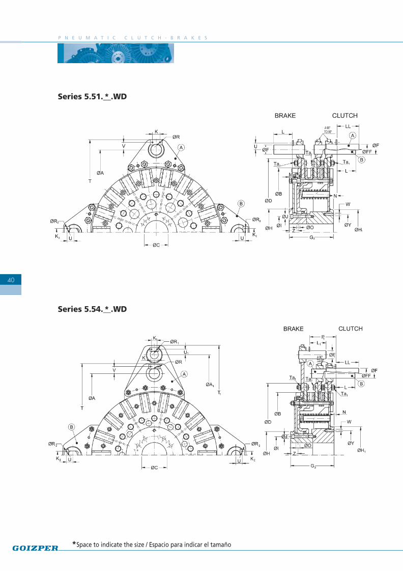
La serie 5.5 corresponde a las ejecuciones defreno-embrague con doble disco en el lado delembrague, con objeto de conseguir una menorinercia. Sus tapas exteriores y moyús estánfabricados en acero electrosoldado.
La serie 5.6 es similar a la 5.5, pero se diferenciaen que lleva doble disco tanto en el lado delembrague como en el del freno con lo que larelación par-inercia mejora.
Series 5.5 corresponds to clutch-brakes withdouble disc in the clutch side, in order to geta lower inertia. Their external covers and hubsare made of electro-welded steel.
Series 5.6 is similar to 5.5 but has double discin both sides, improving the torque-inertia rate.
CLUTCH-BRAKESSERIES 5.5 and 5.6
FRENO-EMBRAGUESSERIES 5.5 y 5.6
Series 5.5 Series 5.6
P N E U M A T I C C L U T C H - B R A K E S
40
Series 5.51.__.WD
Series 5.54.__.WD*
*Space to indicate the size / Espacio para indicar el tamaño
*
F R E N O - E M B R A G U E S N E U M Á T I C O S
41
*The measurements between brackets are in the case of lateral air feeding
*El valor entre paréntesis es para casos de entrada lateral de aire
55140004250
9501583,23
1,53
69588554260114620403050190
180(206)*1801321735253580601007,515161336,55,56,5780950272032
M1215536,5148
75204005900
8502115,9
4,7451,93,977099059960125680454055209
190(225)*19015017453535908011012,517,5161358,56,56,5870
1 07529,527
38,5M1216541230
773840011500
70042417,716,272,96,8970123575590160865554565260
240(276)*24018622,5453545110901301420201748,56,58,5
1090133538,529,543,5M1621053450
76286008700
75031310,410,12,45,2880113567575
145775554565
242225(265)*
22516818,5453545
11090
130142020
1608,56,58,5
1000122038,529,543,5M1618548
230
786160017700
55072239
36,364,310,3114014508851151801000655575331
300(330)*300212284545451301101602020282258,58,58,5
1285157043,538,548,5M1825067450
799020027800
40011208065613
1300-
1000140220114575-
853613763762903260-
60150
-18057,516,532-
10,5--
1460-
51----
76780
1842001370
140066
0,710,6370,71,24956353804580435302240134
140(145)*14095
13,535252560458041512906,55,55,5560680201627M81102654
SizeClutch torqueBrake torquePressure barMax speed min-1
Int.Ext.
New volum.Max. wear Volum.
Ø AØ A1Ø B Min
MaxØ DØ FØ F1Ø FF
G3Ø HØ H1Ø IØ J
KK1K2LL1LLMN
Ø O 2 a 180°P1
Ø RØ R1Ø R2
TT1UU1VW
Ø YZTa1
Nm
dm3
Ø CH7
3690002930
11001121,831,7751 ,12,261079046650
108535403050
169160(190)*
16012313,53525358060
10061514
1206,55,56,5695855272032
M121323195
Weight Kg
5,5
Series 5.51.__.WD / 5.54.__.WD81
13800035500
350168015515010,917,5146518551140150260127690751004004284283404060606018015021057,519,535
217,510,510,510,51650201560
52,5652434085
1590
Kg m2J
Nm

P N E U M A T I C C L U T C H - B R A K E S
42
Series 5.61.__.WD
Series 5.64.__.WD*
*Space to indicate the size / Espacio para indicar el tamaño
*

F R E N O - E M B R A G U E S N E U M Á T I C O S
43
Series 5.61.__.WD / 5.64.__.WD
5,5
55140008500
95019443
1,53
69588554260114620405050190
180(206)*180132173535358090100381516
36,51336,56,56,5780970273232
M1215536,5148
752040011800
8502577,44,741,93,977099059960125680455555209
190(225)*190150174545359010011038
17,516351358,58,56,5870107529,538,538,5M1216541230
773840023000
70051922,116,272,96,8970123575590160865556565260
240(276)*24018622,5454545110110130482020471748,58,58,5
1090135538,543,543,5M1621053450
762860017400
75037712,610,12,45,2880113567575145775556565242
225(265)*22516818,5454545110110130482020
42,51608,58,58,5
1000122038,543,543,5M1618548230
786160035400
55088049
36,364,310,3114014508851151801000657575331
300(330)*30021228454545130130160582028
56,52258,58,58,5
1285160043,548,548,5M1825067450
799020055600
40013409965613
1300-
1000140220114575-
853613763762903260-
60150
-180
-16,532--
10,5--
1460-
51----
76780
1842002740
140066
0,710,630,71,24956353804580435302040134
140(145)*14095
13,5353525607080331512
28,5906,55,55,5560680202727M81102654
SizeClutch torqueBrake torquePressure barMax speed min-1
Int.Ext.
New volum.Max. wear Volum.
Ø AØ A1Ø B Min
MaxØ DØ FØ F1Ø FF
G4Ø HØ H1Ø IØ J
KK1K2LL1LLMN
Ø O 2 a 180°PP1
Ø RØ R1Ø R2
TT1UU1VW
Ø YZTa1
Nm
dm3
Ø CH7
3690005860
11001382,31,771,12,261079046650108535405050169
160(190)*16012313,53535358090100381514391206,56,56,5695875273232
M121323195
*The measurements between brackets refer to clutch-brakes with lateral air feeding
*El valor entre paréntesis es para casos de entrada lateral de aire
8113800071000
350190019014010,618,2146518551140150260127690751004004284283404060606018015021030
19,53550
217,510,510,510,51650201560
52,5652434085
1590
Kg m2J
Weight Kg
Nm

P N E U M A T I C C L U T C H - B R A K E S
44
Series 5.51.__. WDMounting between frame and flywheel by meansof 4 pins at 90º on the clutch side and 2 pins onthe brake side all of them on the same diameter.Fixed in the shaft by locking ring.
Montaje entre bastidor y volante con 4 bulonesa 90º en el lado embrague y 2 bulones en el ladofreno situados todos ellos en el mismo diámetro.Montado en el eje con anillo de fijación.
Series 5.54.__. ADMounting at shaft and by means of 4 pins at 90ºon the clutch side and 2 pins on brake side ondifferent diameters.Lateral air feeding.
Montaje en el extremo del eje con 4 bulones a90º en el lado embrague y 2 bulones en el ladofreno situados en diámetros distintos.Alimentación lateral de aire.
Series 5.64.__. WDMounting at shaft and by means of 4 pins at 90ºon the clutch side and 2 pins connected to doublediscs on brake side, on different diameters.
Montaje en el extremo del eje con 4 bulones a90º en el lado embrague y 2 bulones conectadosa doble disco en el lado del freno, situados endiámetros distintos.
Series 5.61.__. WDMounting between frame and flywheel by meansof 4 pins at 90º on the clutch side and 4 pins at90º on the brake side, all of them on the samediameter.
Montaje entre bastidor y volante con 4 bulonesa 90º en el lado embrague y 4 bulones a 90º enel lado freno, situados todos ellos en el mismodiámetro.
ASSEMBLY EXAMPLES / EJEMPLOS DE MONTAJE

Series 5.7 Size
Ø A
MinØ C
Max
Ø E
G
H
L
Ø P
Ø S
Ø T - 4 x 90º
Ø U
Weight kg.
J kgm2
50
101
44
52
31
1,5
16
36
10,5
M 6
52
1
0,0018
10-13
128
50
65
31
2,5
16
36
10,5
M 6
52
1,8
0,0044
19N
175
45
95
34
3
20
44
13,5
M 8
65
3,75
0,014
36
193
68
110
37,5
3
25
56
16,5
M 10
80
4,8
0,024
75
275
90
155
47
3
35
56
18,5
M 12
112
13,55
0,136
76
315
100
172
47
3
35
80
25
M 16
112
17,2
0,232
77
312
125
180
47
3
35
80
25
M 16
112
15,4
0,209
78
346
125
200
53
3
35
80
25
M 16
112
22
0,317
80
395
140
220
60
3
35
98
25
M 16
132
29,4
0,596
81
448
150
240
60
3
35
98
25
M 16
132
58,3
0,88
37N
214
70
115
37,5
3
25
56
16,5
M 10
80
6
0,032
25N
196
45
100
34
3
20
48
13,5
M 8
70
4,8
0,021
18
156
60
90
34
3
20
44
13,5
M 8
65
2,5
0,0096
55
250
70
130
39,5
3
35
56
18,5
M 12
80
9,13
0,078
82
502
170
270
66
3
41
100
25
M 16
135
57
1,644
F R E N O - E M B R A G U E S N E U M Á T I C O S
45
En los casos en que el freno-embrague estésituado en el extremo del eje, puede seralimentado por medio de un disco dealimentación lateral suministrado por GOIZPERy que va atado al eje por medio de 4 tornillos.
De esta forma, el eje es más corto y se evitamecanizar los agujeros de alimentación de aire.
When the clutch-brake is mounted at the shaftend, it can be fed by a lateral air inlet.
In this way, the shaft is shorter and it eliminatesthe need to drill the shaft.
DISCO DE ALIMENTACIÓN LATERALAIR INLET DISC
M 22 x 1,5 M 27 x 1,5 M 35 x 1,5 M 50 x 1,5 M 65 x 1,5
Series 5.0 Size
Ø A
MinØ C
Max
Ø E
G
H
L
Ø P
Ø S
Ø T - 4 x 90º
Ø U
Weight kg.
J kgm2
60
105
44
52
31
1,5
16
36
10,5
M 6
52
1,1
0,0020
10
126
44
65
31
2,5
16
36
10,5
M 6
52
1,8
0,0040
18
145
55
80
34
3
20
44
13,5
M 8
65
2,3
0,0068
36
188
68
108
37,5
3
25
56
16,5
M 10
80
4,6
0,023
55
205
70
114
39,5
3
35
56
18,5
M 12
80
5,5
0,031
75
225
70
125
41
3
35
56
18,5
M 12
80
6,6
0,058
76
265
75
145
44
3
35
56
18,5
M 12
80
11
0,116
77
275
100
160
47
3
35
80
25
M 16
112
12
0,125
78
330
115
180
53
3
35
80
25
M 16
112
19
0,302
M 22 x 1,5 M 27 x 1,5 M 35 x 1,5 M 50 x 1,5
El disco de alimentación lateral también puedeser usado en las series 5.5 y 5.6.
The lateral air feeding can be also used in theseries 5.5 and 5.6
ACCESORIOSACCESSORIES
P N E U M A T I C C L U T C H - B R A K E S
46
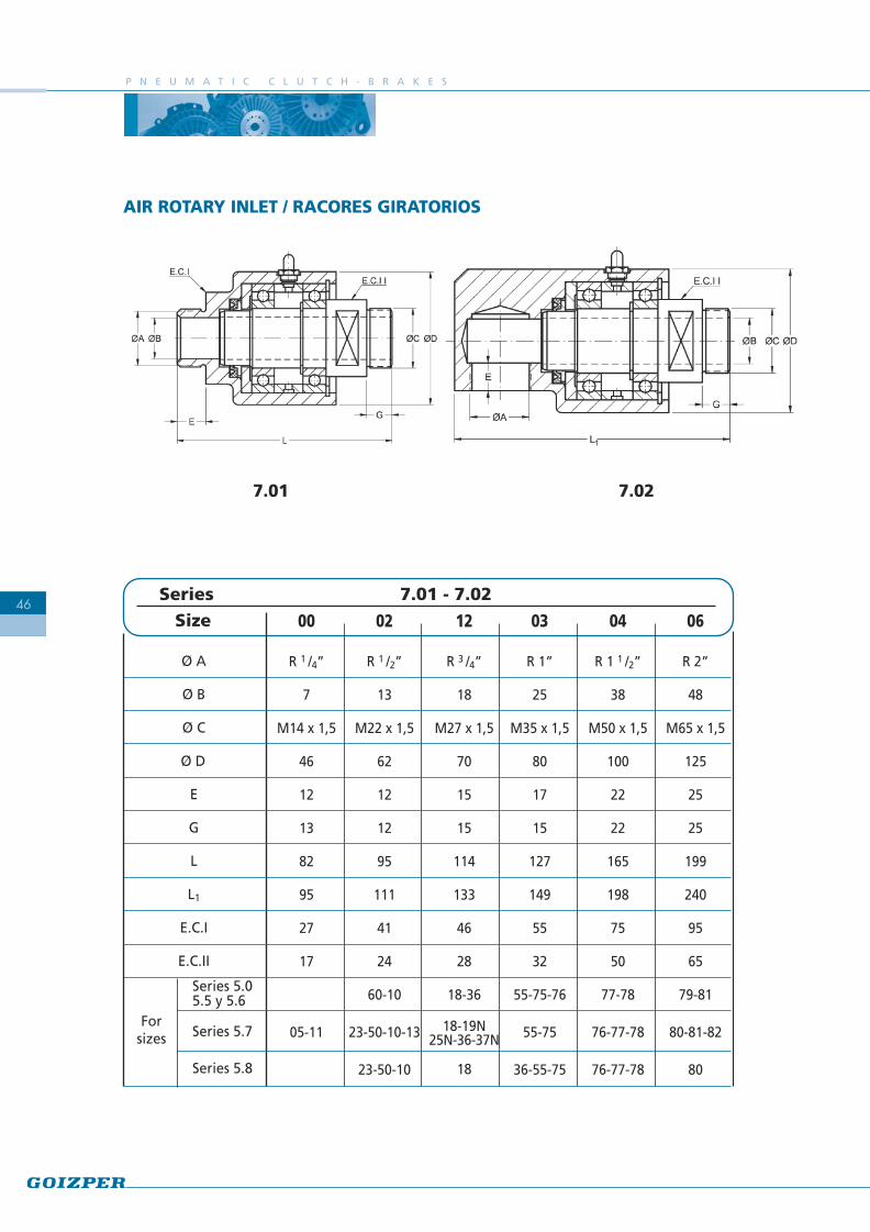
AIR ROTARY INLET / RACORES GIRATORIOS
00
R 1 /4”
7
M14 x 1,5
46
12
13
82
95
27
17
05-11
Size
Ø A
Ø B
Ø C
Ø D
E
G
L
L1
E.C.I
E.C.II
Series 5.05.5 y 5.6
Series 5.7
Series 5.8
12
R 3 /4”
18
M27 x 1,5
70
15
15
114
133
46
28
18-36
18-19N25N-36-37N
18
02
R 1 /2”
13
M22 x 1,5
62
12
12
95
111
41
24
60-10
23-50-10-13
23-50-10
Series 7.01 - 7.02
Forsizes
04
R 1 1 /2”
38
M50 x 1,5
100
22
22
165
198
75
50
77-78
76-77-78
76-77-78
03
R 1”
25
M35 x 1,5
80
17
15
127
149
55
32
55-75-76
55-75
36-55-75
06
R 2”
48
M65 x 1,5
125
25
25
199
240
95
65
79-81
80-81-82
80
7.027.01

F R E N O - E M B R A G U E S N E U M Á T I C O S
47
QUICK EXHAUST ACCESSORY / ACCESORIO DE ESCAPE RÁPIDO
Series 7.06
Size
Ø A
Ø B
Ø D
Ø E
Ø F
Ø G
H
J
K
L
M
N
E.C.
Weight kg
Inertia Kgm2
Series 5.0
Series 5.7
Series 5.8
Forsizes
02
M 22 x 1,5
M 22 x 1,5
123
13
8
10.25
72
12
14
7
20
45,5
32
1,7
0,0037
60-10
50-10
23-50-10
12
M 27 x 1,5
M 27 x 1,5
160
18
9
10.25
91
15
18
9
23
47,5
41
3,8
0,0154
18-36
18-25-36
18
03
M 35 x 1,5
M 35 x 1,5
185
25
12
10.25
98
15
18
10
31
47,5
55
5,5
0,0293
55-75-76
55-75
36-55-75
04
M 50 x 1,5
M 50 x 1,5
230
36
14
12.25
119
22
18
14
40
45
75
9,6
0,0738
77-78-79
76-77-78
76-77-78
06
M 65 x 1,5
M 65 x 1,5
250
48
19
12.25
134
25
21
14
52
41,5
95
15,7
0,214
80
ASSEMBLY EXAMPLES / EJEMPLOS DE MONTAJE
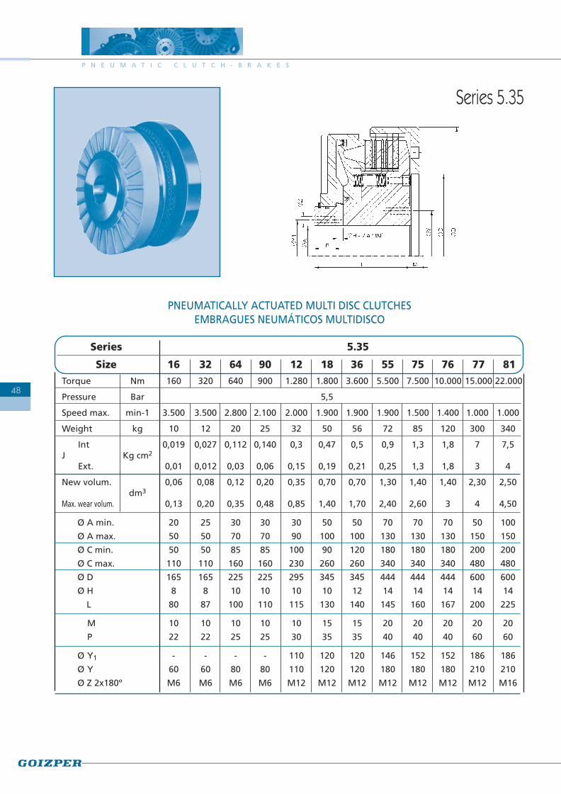
PNEUMATICALLY ACTUATED MULTI DISC CLUTCHESEMBRAGUES NEUMÁTICOS MULTIDISCO
Series 5.35
Series 5.35
Size 16 32 64 90 12 18 36 55 75 76 77 81Torque Nm 160 320 640 900 1.280 1.800 3.600 5.500 7.500 10.000 15.000 22.000
Pressure Bar 5,5
Speed max. min-1 3.500 3.500 2.800 2.100 2.000 1.900 1.900 1.900 1.500 1.400 1.000 1.000
Weight kg 10 12 20 25 32 50 56 72 85 120 300 340
Int 0,019 0,027 0,112 0,140 0,3 0,47 0,5 0,9 1,3 1,8 7 7,5J Kg cm2
Ext. 0,01 0,012 0,03 0,06 0,15 0,19 0,21 0,25 1,3 1,8 3 4
New volum. 0,06 0,08 0,12 0,20 0,35 0,70 0,70 1,30 1,40 1,40 2,30 2,50dm3
Max. wear volum. 0,13 0,20 0,35 0,48 0,85 1,40 1,70 2,40 2,60 3 4 4,50
Ø A min. 20 25 30 30 30 50 50 70 70 70 50 100
Ø A max. 50 50 70 70 90 100 100 130 130 130 150 150
Ø C min. 50 50 85 85 100 90 120 180 180 180 200 200
Ø C max. 110 110 160 160 230 260 260 340 340 340 480 480
Ø D 165 165 225 225 295 345 345 444 444 444 600 600
Ø H 8 8 10 10 10 10 12 14 14 14 14 14
L 80 87 100 110 115 130 140 145 160 167 200 225
M 10 10 10 10 10 15 15 20 20 20 20 20
P 22 22 25 25 30 35 35 40 40 40 60 60
Ø Y1 - - - - 110 120 120 146 152 152 186 186
Ø Y 60 60 80 80 110 120 120 180 180 180 210 210
Ø Z 2x180º M6 M6 M6 M6 M12 M12 M12 M12 M12 M12 M12 M16
P N E U M A T I C C L U T C H - B R A K E S
48
F R E N O - E M B R A G U E S N E U M Á T I C O S
49
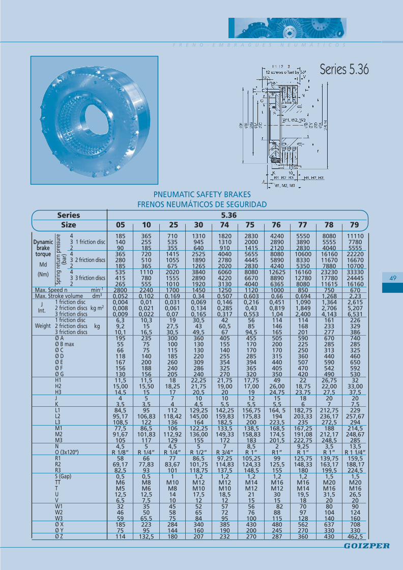
Series 5.36
Series 5.36Size 05 10 25 30 74 75 76 77 78 79
43 1 friction disc243 2 friction discs243 3 friction discs2
Max. Speed n min-1
Max. Stroke volume dm3
1 friction disc2 friction discs kg m2
3 friction discs1 friction disc2 friction discs kg3 friction discsØ AØ B maxØ CØ DØ EØ FØ GH1H2H3JKL1L2L3M1M2M3NO (3x120º)R1R2R3S (Gap)TTTUVW1W2W3Ø XØ YØ Z
1851409036528018553541526528000,0520,0040,0080,0096,39,210,1195556611816715613011,515,0014,5
43,584,595,17108,577,591,671054,5
R 1/8”58
69,1782,50,5M6M512,56,532465918575114
365255185720510365111078055522400,1020,010,0210,02210,315
16,5235757514020018815611,515,50
155
3,595
106,8312286,5
101,831175
R 1/4”66
77,83930,5M8M612,57,53550
65,522395
132,5
7105353551415105567520201555101017000,1690,0310,0610,0719
27,530,530010011518526024020518
18,251774
112118,42
136106
112,921294,5
R 1/4”77
83,671011
M10M81410455875284144180
131094564025251890126538402890192014500,340,0690,1340,16530,543
49,5360130130220309286240
22,2521,7520,5104,5
129,25145,00
164122,25136,00
1555
R 1/2”86,5
101,75118,75
1,2M12M1017,512526584340160207
1820131091040402780202060604220313012500,5070,1460,2850,317
4260,567405155140255354325270
21,7519,00
20105,5
142,25159,83182,5133,5149,33
1727
R 3/4”97,25114,83137,51,2
M12M1018,512577295385190232
28302000141556554445283080806670404011200,6030,2160,43
0,5535685
94,5455170170285394365320
17,7517,00
19125,5
156,75175,83
200138,5158,83
1838,5
R 1”105,25124,33148,51,2
M14M1221155676100430200270
424028902120808058904240126258890636510000,660,4510,8191,0411414616550520017031544040535049
26,0024,75
155,5
164, 5194
223,5168,5174,5201,5
2R1”99
125,51551,2
M16M123015
8288115480245287
555038902830106008330535016160127808080850
0,6941,0901,8492,40011416820159022525036050747042022
18,7523,75
186
182,75203,33
235167,25191,08222,759,25R 1”
125,75148,33
1801,2
M16M1419,5187097128562270360
80805555404016160116707880232301778011615750
1,2681,3642,7064,143161233277670285313440590542490
26,7522,0027,5207
212,75236,17272,5188
212,17248,53,5
R 1”139,75163,17199,51,5
M20M1631,52080104140637330430
11110778055552222016670107003333024445161606702,232,6155,2076,53122632938674028532546065059253032
33,0037,5207,5229
257,67294
214,5248,67
28513,5
R 1 1/4”159,5
188,17224,51,5
M20M1626,52090
124160708330
462,5
Dynamicbraketorque
Dynamicbraketorque
Sprin
g re
turn
pre
ssur
e(b
ar)
Md
(Nm)
JInt.
Weight
PNEUMATIC SAFETY BRAKESFRENOS NEUMÁTICOS DE SEGURIDAD

P N E U M A T I C C L U T C H - B R A K E S
50

F R E N O - E M B R A G U E S N E U M Á T I C O S
51
Éste es el freno-embrague multidisco actuadoneumáticamente y refrigerado por aceite.
Esta serie de freno-embrague combina elaccionamiento del embrague neumático conla capacidad de refrigeración de los embragueshidráulicos. Como resultado tenemos un freno-embrague con la posibilidad de obtener unaalta frecuencia de maniobras.
La refrigeración se produce dependiendo dela energía de disipación requerida por laaplicación, esta refrigeración puede ser forzadapor medio de un circuito exterior, para lo cualel freno-embrague está preparado.
This series of clutch-brake is the version of thepneumatic actuated and hidraulicallyrefrigerated multiplate clutch-brake.
It combines the engagement of the pneumaticclutch-brake, with the refrigeration capacityof the hydraulic clutch-brakes. As a result, weobtain a clutch-brake with the possibility of ahigh frequency of engagements.
The disc refrigeration could be plunged in oil,(no external circuit) or with a forcedrefrigeration or external circuit, depending onthe required disipation energy of the aplication.
WET CLUTCH-BRAKESERIES 5.W
FRENO-EMBRAGUEOLEONEUMÁTICO SERIE 5.W

P N E U M A T I C C L U T C H - B R A K E S
52
Series 5.W1
Series 5.W5
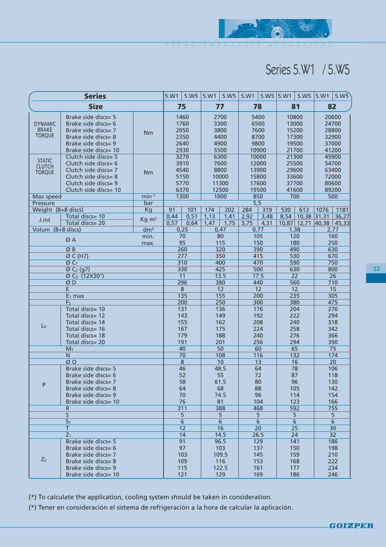
F R E N O - E M B R A G U E S N E U M Á T I C O S
53
Size 75 77 78 81 82Brake side discs= 5Brake side discs= 6Brake side discs= 7Brake side discs= 8Brake side discs= 9Brake side discs= 10Clutch side discs= 5Clutch side discs= 6Clutch side discs= 7Clutch side discs= 8Clutch side discs= 9Clutch side discs= 10
Max speedPressureWeight (8+8 discs)
Total discs= 10Total discs= 20
Volum (8+8 discs)
Ø BØ C (H7)Ø C1
Ø C2 (g7)Ø C3 (12X30°)Ø DEE1 maxF2
Total discs= 10Total discs= 12Total discs= 14Total discs= 16Total discs= 18Total discs= 20M1
NØ OBrake side discs= 5Brake side discs= 6Brake side discs= 7Brake side discs= 8Brake side discs= 9Brake side discs= 10RSS1
TZ1
Brake side discs= 5Brake side discs= 6Brake side discs= 7Brake side discs= 8Brake side discs= 9Brake side discs= 10
206002470028800329003700041200459005470063400720008060089200500
2,7716025063067075080026710153054752702943183423663907517420106118130142154166755563032186198210222234246
DYNAMICBRAKE
TORQUE
Series 5.W1 / 5.W5
STATICCLUTCHTORQUE
Nm
Nm
min-1
barKg
Kg m2
dm3
min.max.
118136,2745,33
107631,3140,38
108001300015200173001950021700213002550029600336003770041600700
1,3812018049053059063022560122353802042222402582762946513216788796105114123592562524141150159168177186
61310,3812,71
5308,5410,87
5400650076008700980010900100001200013900158001760019500850
0,7710515039041547050017.544012200300176192208224240256601161364728088961044685620
26.5129137145153161169
3193,484,31
2842,923,75
2700330038004400490055006300760088001000011300125001000
0,478011532035040042513.5380121552501361491621751882015010810
48.555
61.568
74.5813885616
14.596.5103
109.5116
122.5129
2021,411,75
1741,131,47
1460176020502350264029303270391045405150577063701300
0,257095260277310330112968
135200131143155167179191407084652586470763115612149197103109115121
1010,510,64
910,440,57J.int
Ø A
L0
P
Z2
5.W1 5.W5 5.W1 5.W5 5.W1 5.W5 5.W1 5.W5 5.W1 5.W5Series
5,5
(*) To calculate the application, cooling system should be taken in consideration.
(*) Tener en consideración el sistema de refrigeración a la hora de calcular la aplicación.
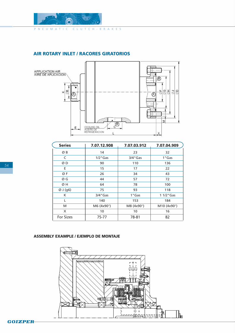
P N E U M A T I C C L U T C H - B R A K E S
54
AIR ROTARY INLET / RACORES GIRATORIOS
ASSEMBLY EXAMPLE / EJEMPLO DE MONTAJE
Series
Ø B
C
Ø D
E
Ø F
Ø G
Ø H
Ø J (g6)
K
L
M
X
For Sizes
7.07.12.908
14
1/2"Gas
90
15
26
44
64
75
3/4"Gas
140
M6 (4x90°)
10
75-77
7.07.03.912
23
3/4"Gas
110
17
34
57
78
93
1"Gas
153
M8 (4x90°)
10
78-81
7.07.04.909
32
1"Gas
136
22
43
72
100
118
1 1/2"Gas
184
M10 (4x90°)
16
82

Only brake version. It is in fact a safety pneumaticbrake.
Versión solo freno. Es en realidad un frenoneumático de seguridad.
Clutch-brake unit with quick exhaust. To get veryquick braking response time.
Freno-embrague con escape rápido. Se consiguent i e m p o s d e r e s p u e s t a e n f r e n a d aconsiderablemente bajos.
Clutch-brake with planetary gear.
Freno-embrague con reductor planetario.
SPECIAL CLUTCH-BRAKE UNITS FRENO-EMBRAGUES ESPECIALES
F R E N O - E M B R A G U E S N E U M Á T I C O S
55
Pneumatic safety brake.
Freno neumático de seguridad.
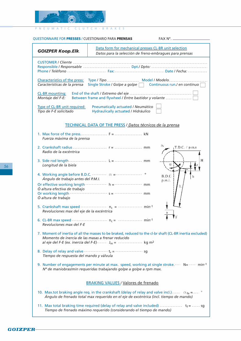
Data form for mechanical presses CL-BR unit selectionGOIZPER Koop.Elk. Datos para la selección de freno-embragues para prensas
CUSTOMER / ClienteResponsible / Responsable Dpt./ Dpto:Phone / Teléfono Fax: Date / Fecha:
Characteristics of the press: Type / Tipo Model / ModeloCaracterísticas de la prensa Single Stroke / Golpe a golpe Continuous run./ en continuo
CL-BR mounting: End of the shaft / Extremo del ejeMontaje del F-E: Between frame and flywheel / Entre bastidor y volante
Type of CL-BR unit required: Pneumatically actuated / NeumáticoTipo de F-E solicitado Hydraulically actuated / Hidráulico
TECHNICAL DATA OF THE PRESS / Datos técnicos de la prensa
1. Max force of the press. F = kNFuerza máxima de la prensa
2. Crankshaft radius r = mmRadio de la excéntrica
3. Side rod length L = mmLongitud de la biela
4. Working angle before B.D.C. a = ºÁngulo de trabajo antes del P.M.I.
Or effective working length h = mmÓ altura efectiva de trabajoOr working length s = mmÓ altura de trabajo
5. Crankshaft max speed nc = min-1
Revoluciones max del eje de la excéntrica
6. CL-BR max speed nc = min-1
Revoluciones max del F-E
7. Moment of inertia of all the masses to be braked, reduced to the cl-br shaft (CL-BR inertia excluded)Momento de inercia de las masas a frenar reducidoal eje del F-E (ex. inercia del F-E) Jm = kg m2
8. Delay of relay and valve tr = sgTiempo de respuesta del mando y válvula
9. Number of engagements per minute at max. speed, working at single stroke. N= min-1
Nº de maniobras/min requeridas trabajando golpe a golpe a rpm max.
BRAKING VALUES / Valores de frenado
10. Max.tot braking angle req. in the crankshaft (delay of relay and valve incl.) afe = °Ángulo de frenado total max requerido en el eje de excéntrica (incl. tiempo de mando)
11. Max total braking time required (delay of relay and valve included) tf = sg Tiempo de frenado máximo requerido (considerando el tiempo de mando)
FAX Nº.QUESTIONNAIRE FOR PRESSES / CUESTIONARIO PARA PRENSAS
P N E U M A T I C C L U T C H - B R A K E S
56

57
FAX Nº.QUESTIONNAIRE FOR APPLICATIONS IN GENERAL / CUESTIONARIO PARA APLICACIONES EN GENERAL
Operating conditions / Condiciones del accionamiento:Stationary / Estático: Full load / Plena carga: Without load / Sin carga:Initial driver speed / Velocidad inicial del conductor: n10= min-1
Initial driven speed / Velocidad inicial del conducido: n20= min-1
Max. Speed / Velocidad máxima: nmax= min-1
Moments of inertia reduced to CL-BR / Momento de inercia reducido al freno-embrague:Driver side / Parte conductora: JA= kgm2
Driven side / Parte conducida: JL= kgm2
Times / Tiempos:Braking time / Tiempo de frenada: t3= sClutching time / Tiempo de embragado: t3= s
Operating frecuency / Frecuencia de accionamiento: N= min-1
Data form for CL-BR unit selectionGOIZPER Koop.Elk. Datos para la selección de freno-embragues
CUSTOMER / ClientePhone / Teléfono Fax: Date / Fecha:
Type of CL-BR unit required / Tipo de freno-embrague solicitado:Pneumatic / Neumático: Hydraulic / Hidráulico:Electromagnetic / Electromagnético: Mechanic / Mecánico:
Machine Type / Tipo de máquina:Drive machine / Máquina motriz:
Type / Tipo:Electric Motor / Motor eléctrico:Combustion engine / Motor de combustión:Hydraulic motor / Motor hidráulico:Other / Otro:
Power / Potencia P= KwSpeed / Velocidad: n= min-1
Reduction to CL-BR / Reducción al freno embrague:
Mounting / Montaje:Rotary axis / Eje de rotación:
Horizontal: Vertical:
CL-BR situation / Situación de freno-embrague:Exposed / Expuesto: Closed housing / Alojamiento cerrado:Shaft diameter / Diámetro de ejes:
Driver side / Parte conductora: mm.Driven side / Parte conducida: mm.
Required torque on clutches or brakes / Par necesario en el freno-embrague:Engaging dynamic torque / Par de accionamiento dinámico: Ms= NmTransmissible static torque / Par estático transmisible: Mt= NmCurbe or value of load torque / Curva o valor del par de carga: ML= Nm
F R E N O - E M B R A G U E S N E U M Á T I C O S
GOIZPER S. COOP. LTDA. reserves the right to change the designs and/or dimensions of the products shown in this brochure without prior notice.
San Sebastian
Bilbao
VitoriaPamplona
Biarritz
Antzuola
Bilbao
VitoriaPamplona
Biarritz
Antzuola
San Sebastián
E-mail:[email protected]
Tel: (34) 943 78 60 00Fax: (34) 943 78 70 95
211 - 20570 BERGARA
GUIPUZCOA - SPAIN
EN ISO 9001:2000
Certificate: 01 100 5695
S. COOP.
C/ Antigua, 4 - 20577 ANTZUOLA
D.L
./L.G
. SS
-99-
2008
Recommended