Fortessa_FTK5_Instructions_Rev01
1
FTK5 PROXIMITY KEYPAD
Before using the unit, please read the instructions and retain for future reference
Fortessa_FTK5_Instructions_Rev01
2
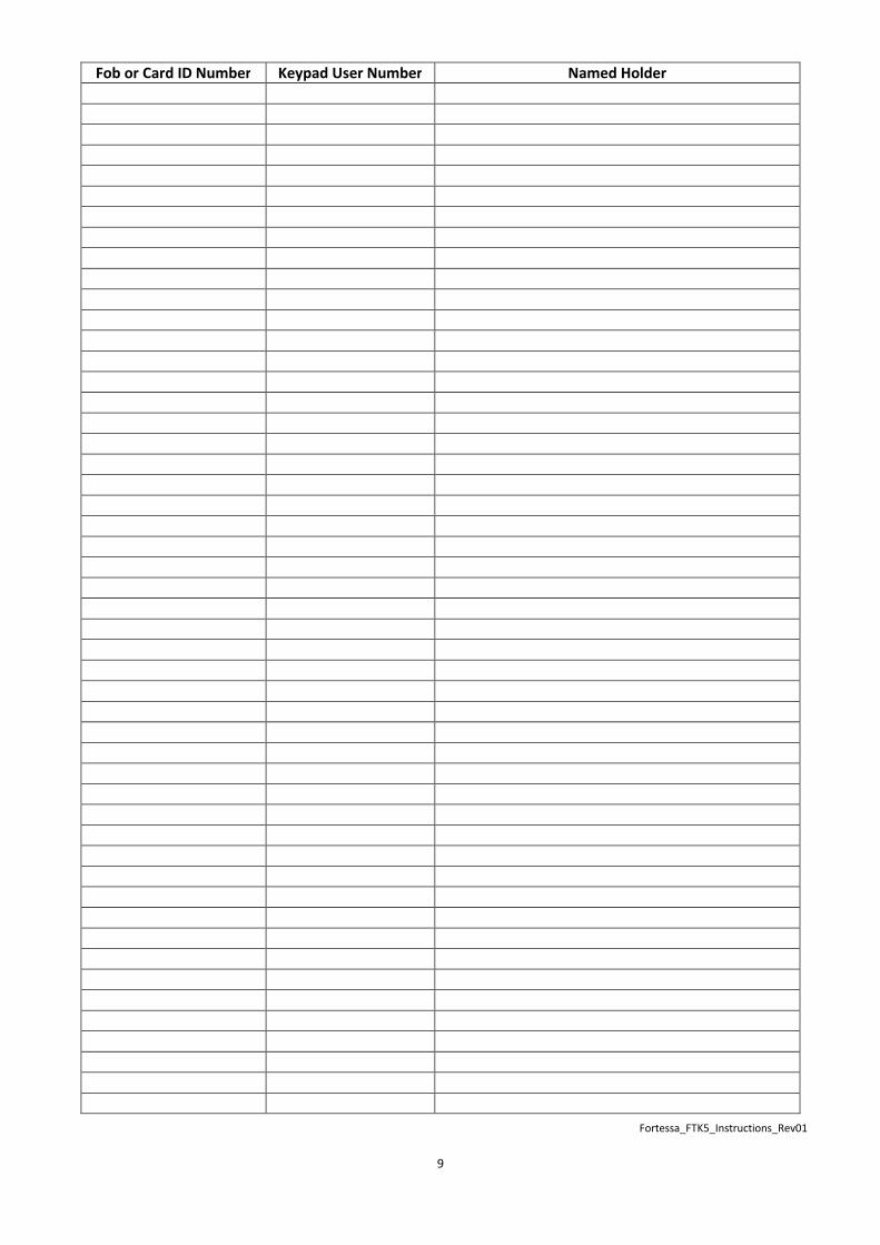
There are 600 user codes (fobs or cards) and 1 programming code:
Careful administration records will be required for future reference, please refer to last page of the instructions for an
example sheet.
Important Note:
If a code is required then this has to be programmed with a fob or card
To add fob or card
From quiescent state: Constant Blue LED (default)
Enter programming code: i.e. 1 2 3 4, 1 2 3 4 (default unless changed) – Long beep, Yellow LED
Enter user ID from 001-600: i.e. � 002 (alternating flashing green/amber) if you hear a double bleep and constant green LED then
the user ID has already been programmed and will require deleting first before programming
Then: Swipe card/fob (single beep alternating flashing green/amber)
You can then swipe the next card or fob for the next consecutive User ID will be used.
To exit programming mode press: #
To add fob/card and user code
From quiescent state: Constant Blue LED (default)
Enter programming code (default 1234): 1 2 3 4, 1 2 3 4 (unless changed) – Long beep, Yellow LED
Enter user ID from 001-600 i.e: � 0 0 2 (alternating flashing green/amber) if you hear a double bleep and constant green LED then
the user ID has already been programmed and will require deleting first before programming
Enter user code: X X X X - (X=Code) (double beep) then Swipe card/fob (beep)
You can then insert the next user code and swipe fob for the next consecutive User ID will be used.
To exit programming mode press: #
Access Modes:
The keypad can operate in a choice one of 3 modes (default = 0)
0: Either Fob/Card or code
1: Card only
2: Card/Fob & code required
From quiescent state: Constant Blue LED (default)
Enter programming code (default 1234): 1 2 3 4, 1 2 3 4 (unless changed)
Enter: � 8 1 0 M # (M = above modes 0, 1, 2)
Note:
If a button is not pressed within 30 second the keypad will exit the programming menu
Careful administration records will be required for future reference, please refer to last page of the instructions for example sheet

Fortessa_FTK5_Instructions_Rev01
3
To Change the Lock Output Time (Default 5 Seconds)
From quiescent state: Constant Blue LED (default)
Enter programming code (default 1234): 1 2 3 4, 1 2 3 4 (unless changed) – Long beep, Yellow LED
Enter: � 8 2 0 T T # (T T equals time in seconds i.e. 08 for 8 seconds)
To Delete User ID fob/card and user code
From quiescent state: Constant Blue LED (default)
Enter programming code (default 1234): 1 2 3 4, 1 2 3 4 (unless changed) – Long beep, Yellow LED
Either
To Delete All Users, Enter: � 8 5 0 1 0 0 0 #
To Delete Individual Users: � 8 5 0 1 X X X # - (X = User ID)
To Delete Consecutive Users: � 8 5 0 2 S S S � E E E # (i.e. to delete User ID 015-023),
example enter: � 8 2 015 � 023 # to delete card numbers for 15-23 (X = User ID)
To Change the Programming Code (engineers Code)
This code will only allow access to the programming menu functions and will not operate the lock output
From quiescent state: Constant Blue LED (default)
Enter programming code (default 1234): 1 2 3 4, 1 2 3 4 (unless changed) – Long beep, Yellow LED
Enter: � 0 0 0 (double bleep, constant amber LED)
Enter New Programming code: X X X X #
To Insert a Programming Card/Fob (This Card/Fob will not operate the Lock)
This card/fob will only allow access to the programming menu functions and will not operate the lock output
From quiescent state: Constant Blue LED (default)
Enter programming code (default 1234): 1 2 3 4, 1 2 3 4 (unless changed) – Long beep, Yellow LED
Enter: � 8 8 8 (double bleep, constant amber LED)
Then Swipe card/fob (beep)
BACKLIGHT MODE
Backlit Mode Description
0 Disabled No backlit Light - only illuminates on key press
1 Enable Always On
2 Automatic + Timer
Back light illuminates when a key pressed or fob/card
and remains illuminated for 10 seconds after the last key
press
From quiescent state: Constant Blue LED (default = 1)
Enter programming code (default 1234): 1 2 3 4, 1 2 3 4 (default unless changed)
Enter: � 8 5 9 X # - (X = Backlit Mode)
To programme AUX Code
The AUX Code operates the AUX Output (no default code)
From quiescent state: Constant Blue LED (default)
Enter programming code (default 1234): 1 2 3 4, 1 2 3 4 (unless changed) – Long beep, Yellow LED
Enter: � 840 X X X X # - (X = AUX Code) Swipe Card/fob if required

Fortessa_FTK5_Instructions_Rev01
4
Keypad Lock Out – Incorrect Code Entry
Option to lock the keypad for 30 seconds on 4 incorrect code entries only, when the keypad is in the lock mode the
proximity sensor is also disabled
From quiescent state: Constant Blue LED (default)
Enter programming code (default 1234): 1 2 3 4, 1 2 3 4 (default unless changed)
Enter: � 8 5 1 #
Repeat above process to toggle on or off
Change Incorrect Code Input Mode (Default 1)
Option for inputting of codes
20 Digit = 0: You can enter up to 20 digits to enter the code without an error tone
Code Set = 1: You can only enter 4 digits before an error tone (if programmed for 4 number code)
From quiescent state: Constant Blue LED (default)
Enter programming code (default 1234): 1 2 3 4, 1 2 3 4 (default unless changed)
Enter: � 8 5 3 0 # - For 20 consecutively digit number entry before error tone
Enter: � 8 5 3 1 # - For Code Set, 4 digit number entry before error tone if incorrect code entered & depending on
code length
Change Toggle Code
Toggle code once entered will permanently override the lock until the Toggle code has been re-entered (i.e. for
deliveries).
Note: For the toggle code to operate the Toggle Mode will need to be set. This mode NOT suitable for failsecure locks.
From quiescent state: Constant Blue LED (default)
Enter programming code (default 1234): 1 2 3 4, 1 2 3 4 (default unless changed)
Enter: � 8 5 4 X X X X # - (X = Bypass Code)
Change Toggle Mode (default = normal mode)
Option required if Toggle Code is required, when the Toggle Code has been entered the lock will operate and remain
unlocked until the Toggle Code has been re-entered
From quiescent state: Constant Blue LED (default)
Enter programming code (default 1234): 1 2 3 4, 1 2 3 4 (default unless changed)
Enter: � 8 5 2 0 # - Normal Mode
Enter: � 8 5 2 1 # - Bypass Mode
ALARM OUTPUT MODE
Alarm Output Mode Description
0 Disabled Alarm Output Inactive
1 Door Contact 1) Alarm output will activate if the door contact is open
2 Tamper Alarm output will activate on tamper activation
3 1 or 2 Either Mode 1 or 2 will activate the alarm Output
From quiescent state: Constant Blue LED (default)
Enter programming code (default 1234): 1 2 3 4, 1 2 3 4 (default unless changed)
Enter: � 8 5 5 X # - (X = Above Alarm Output Module)

Fortessa_FTK5_Instructions_Rev01
5
To Change Alarm Output Time (Default 030 Seconds)
When the alarm output is activated the keypad tone will also sound, an active fob or code will be required to reset the
keypad
From quiescent state: Constant Blue LED (default)
Enter programming code (default 1234): 1 2 3 4, 1 2 3 4 (unless changed) – Long beep, Yellow LED
Enter: � 8 5 6 T T T # (T T T equals time in seconds i.e. 008 for 8 seconds)
AUX OUTPUT MODE
In mode 5, you trigger AUX but detecting Reed, if Reed is triggered without a correct password or PB.
AUX Output Mode Description
0 Disabled Aux Output Inactive
1 Incorrect Code Operates AUX Output from incorrect code or fob entry
2 Password Error ¹ Incorrect Code or fob entry (dependant on section
Change Code Input Mode)
3 Press the � or the ֠ ¹ This feature could be used as doorbell button which
operates AUX Output
4 Tamper activated ¹ Operates the AUX output
5 Door forced ¹ Door opened (reed activation) with correct code/fob or
push button activation
6 Activate P.B.¹ Operates AUX Output when the push button has been
operated
7 AUX Code AUX code entered activates output
¹ If the AUX output time is left at 000 then operation will not work
AUX Output Mode (See table above)
From quiescent state: Constant Blue LED (default)
Enter programming code (default 1234): 1 2 3 4, 1 2 3 4 (default unless changed)
Enter: � 8 5 7 X # - (X = Above Aux Output Mode)
To Change the AUX Output Time (Default 000 Seconds)
From quiescent state: Constant Blue LED (default)
Enter programming code (default 1234): 1 2 3 4, 1 2 3 4 (unless changed) – Long beep, Yellow LED
Enter: � 8 5 8 T T T # (T T T equals time in seconds i.e. 008 for 8 seconds)
FACTORY RESET or SYSTEM RESTORE
Remove Power to the keypad
Insert the jumper on the printed circuit board marked as “SYSTEM RESTORE”
Restore Power, wait 5 seconds then remove the shorting jumper pin

Fortessa_FTK5_Instructions_Rev01
6
1 Gang Box
Fortessa_FTK5_Instructions_Rev01
7
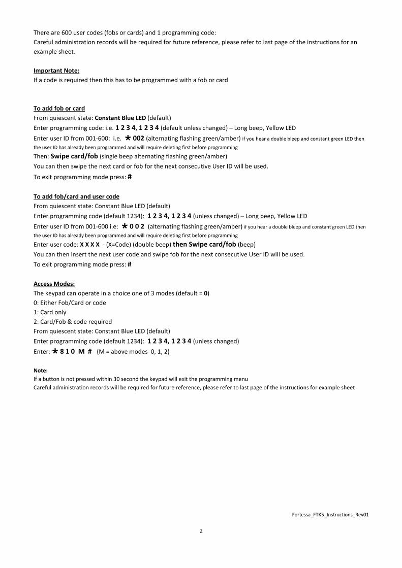
Wiring Diagram Magnetic Lock (Failsafe)
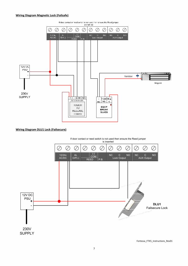
Wiring Diagram DLU1 Lock (Failsecure)
12/24v
AC/DC
AL
O/P(-)
(-)
COM
REED P.B.
NC C NO
Lock Output
NC C NO
AUX Output
12V DC
PSU
-
+
230V
SUPPLY
If door contact or reed switch is not used then ensure the Reed jumper
is inserted
DLU1
Failsecure Lock
Varistor

Fortessa_FTK5_Instructions_Rev01
8
Fob or Card ID Number Keypad User Number Named Holder
Example: 0214561967 028 Mrs J Smith
000
001
002
003
004
005
006
007
008
009
010
011
012
013
014
015
016
017
018
019
020
021
022
023
024
025
026
027
028
029
030
031
032
033
034
035
036
037
038
039
040
041
042
043
044
045
046
047
For Additional fobs please use blank sheet on following page
Fortessa_FTK5_Instructions_Rev01
9
Fob or Card ID Number Keypad User Number Named Holder

Fortessa_FTK5_Instructions_Rev01
10
Quick Reference Table
Function Programming Code Factory Default Changed Notes
Change Master
Password 0 0 0 1 2 3 4
Setup User Password or
Fob 001 – 600 0 0 1 = 3 3 3 3
Access Mode 8 1 0 0 = Card or Code
Lock Output time 8 2 0 5 Seconds
Set AUX Password 8 4 0 None
Delete User 8 5 0
Keypad Lockout
(incorrect entry) 8 5 1 Off
Toggle Mode 8 5 2 0 = Normal Mode
Incorrect Code Input
Mode 8 5 3 0 = 20 key presses
Change Toggle Code 8 5 4 None
Alarm Output Mode 8 5 5 0 = Disabled
Alarm Output Time 8 5 6 0 3 0 = 30 Secs
Change AUX Output
Mode 8 5 7 7 = AUX Password
Change AUX Output
Time 8 5 8 0 0 0 = On/Off
Backlight 8 5 9 1 = Open
8 8 8 None
Specification
26Bit (card) 26 / 34Bit
Power : AC/DC 12~24V +/-10%
Power consumption: 3W
Lock Out: volt free change over contacts Max 24v 3A
Aux Out: volt free change over contacts Max 24v 3A
AL Out (Alarm): Sw- output Max 12v 500mA
Weight: 0.56kg
Size: 79 (W) x 79 (H) x 28 (D)
Card: EM induction card (125 KHz)
Due to our policy of continuous improvement we reserve the right to change specification without
prior notice.
Errors and omissions excepted. These instructions have been carefully checked prior to publication.
However, no responsibility can be accepted by Challenger Security Products for any misinterpretation
of these instructions.
Distributed by:
CHALLENGER SECURITY PRODUCTS
10 Sandersons Way, Blackpool, FY4 4NB
Technical helpline: 01253 792898
Email [email protected]
Website: www.challenger.co.uk
Recommended