I
FWA-3800 User manual Rackmount Internet Security Platform with 6 GbE Front LAN Ports and 1 Console port / 1 USB port/ LCD Display

II
Advantech Internet Security Platform
Copyright Notice
This document is copyrighted, 2006. All rights are reserved. The original manufacturer
reserves the right to make improvements to the products described in this manual at any
time without notice. No part of this manual may be reproduced, copied, translated or
transmitted in any form or by any means without the prior written permission of the
original manufacturer. Information provided in this manual is intended to be accurate and
reliable. However, the original manufacturer assumes no responsibility for its use, nor for
any infringements upon the rights of third parties which may result from its use.
CE Notification
The FWA-3800, developed by Advantech Co., Ltd., has passed the CE test for
environment specifications when shielded cables are used for external wiring. We
recommend the use of shielded cables.
Safety Instructions
1. Read these safety instructions carefully.
2. Keep this user manual for later reference.
3. Disconnect this equipment from AC outlet before cleaning. Do not use liquid or spray
detergents for cleaning.
4. For pluggable equipment, the power outlet shall be installed near the equipment and
shall be easily accessible.
5. Keep this equipment away from humidity.
6. Put this equipment on a reliable surface during installation. Dropping it or letting it
fall could cause damage.
7. Do not leave this equipment in an environment unconditioned where the storage
temperature under 0°C (32°F) or above 40°C (104°F), it may damage the equipment.
8. The openings on the enclosure are for air convection hence protects the equipment
from overheating. DO NOT COVER THE OPENINGS.
9. Make sure the voltage of the power source is correct before connecting the
equipment to the power outlet.
10. Place the power cord such a way that people can not step on it. Do not place
anything over the power cord. The voltage and current rating of the cord should be
greater than the voltage and current rating marked on the product.
11. All cautions and warnings on the equipment should be noted.
12. If the equipment is not used for long time, disconnect it from the power source to
avoid being damaged by transient over-voltage.
13. Never pour any liquid into ventilation openings. This could cause fire or electrical
shock.
III
14. Never open the equipment. For safety reasons, the equipment should be opened only
by qualified service personnel.
15. If any of the following situations arises, get the equipment checked by service
personnel:
(1) The power cord or plug is damaged.
(2) Liquid has penetrated into the equipment.
(3) The equipment has been exposed to moisture.
(4) The equipment does not work well or you cannot get it to work according to user
manual.
(5) The equipment has been dropped and damaged.
(6) The equipment has obvious signs of breakage.
16. CAUTION: The computer is provided with a battery-powered real-time clock circuit.
There is a danger of explosion if battery is incorrectly replaced. Replace only with
same or equivalent type recommended by the manufacture. Discard used batteries
according to the manufacturer’s instructions.
17. THE COMPUTER IS PROVIDED WITH CD DRIVES COMPLY WITH APPROPRIATE
SAFETY STANDARDS INCLUDING IEC 60825.
18. This device complies with Part 15 of the FCC rules. Operation is subject to the
following two conditions:
(1) this device may not cause harmful interference, and
(2) this device must accept any interference received, including interference that
may cause undesired operation.
19. CAUTION: Always completely disconnect the power cord from your chassis whenever
you work with the hardware. Do not make connections while the power is on.
Sensitive electronic components can be damaged by sudden power surges.
20. CAUTION: Always ground yourself to remove any static charge before touching the
motherboard, backplane, or add-on cards. Modern electronic devices are very
sensitive to static electric charges. As a safety precaution, use a grounding wrist
strap at all times. Place all electronic components on a static-dissipative surface or in
a static-shielded bag when they are not in the chassis.
21. CAUTION: Any unverified component could cause unexpected damage. To ensure the
correct installation, please always use the components (ex. screws) provided with
the accessory box.
CLASS 1 LASER PRODUCT KLASSE 1 LASER PRODUKT

IV
22. Caution text concerning lithium batteries:
23. "Rack Mount Instructions - The following or similar rack-mount instructions are
included with the installation instructions:
(1) Elevated Operating Ambient - If installed in a closed or multi-unit rack
assembly, the operating ambient temperature of the rack environment may be
greater than room ambient. Therefore, consideration should be given to installing
the equipment in an environment compatible with the maximum ambient
temperature (Tma) specified by the manufacturer.
(2) Reduced Air Flow - Installation of the equipment in a rack should be such that
the amount of air flow required for safe operation of the equipment is not
compromised.
(3) Mechanical Loading - Mounting of the equipment in the rack should be such that
a hazardous condition is not achieved due to uneven mechanical loading.
(4) Circuit Overloading - Consideration should be given to the connection of the
equipment to the supply circuit and the effect that overloading of the circuits
might have on overcurrent protection and supply wiring. Appropriate
consideration of equipment nameplate ratings should be used when addressing
this concern.
(5) Reliable Earthing - Reliable earthing of rack-mounted equipment should be
maintained. Particular attention should be given to supply connections other than
direct connections to the branch circuit (e.g. use of power strips)."
Product warranty
Advantech warrants to you, the original purchaser, that each of its products will be free
from defects in materials and workmanship for two year from the date of purchase.
This warranty does not apply to any products which have been repaired or altered by
persons other than repair personnel authorized by Advantech, or which have been
subject to misuse, abuse, accident or improper installation. Advantech assumes no
liability under the terms of this warranty as a consequence of such events.
Because of Advantech’s high quality-control standards and rigorous testing, most of our
customers never need to use our repair service. If an Advantech product is defective, it
will be repaired or replaced at no charge during the warranty period. For out-of-warranty
repairs, you will be billed according to the cost of replacement materials, service time
ADVARSEL! Lithiumbatteri - Eksplosionsfare ved fejlagtig
håndtering.
UDSKIFTNING MÅ KUN SKE MED BATTERI AF SAMME
fabrikat og type. Levér det brugte batteri tilbage tilleverandøren.

V
and freight. Please consult your dealer for more details. If you think you have a
defective product, follow these steps:
1 Collect all the information about the problem encountered. For example, CPU speed,
Advantech products used, other hardware and software used, etc. Note anything
abnormal and list any on-screen messages you get when the problem occurs.
2 Call your dealer and describe the problem. Please have your manual, product,
and any helpful information readily available.
3 If your product is diagnosed as defective, obtain an RMA (return merchandise
authorization) number from your dealer. This allows us to process your return more
quickly.
4 Carefully pack the defective product, a fully-completed Repair and Replacement
Order Card and a photocopy proof of purchase date (such as your sales receipt) in a
shippable container. A product returned without proof of the purchase date is not eligible
for warranty service.
5 Write the RMA number visibly on the outside of the package and ship it prepaid
to your dealer.

VI
Packing List
Before installation, ensure that the following materials have been received:
� One FWA-3800 Internet Security Platform
� One box of accessories
� One warranty certificate
� One CD-ROM for user manual (PDF file) If any of these items are missing or
damaged, contact your distributor or sales representative immediately.
Technical Support and Sales Assistance
If you have any technical questions about the FWA-3800 or any other Advantech
products, please visit our support website at:
� http://www.advantech.com.tw/support
� http://www.advantech.com.
For more information about Advantech's products and sales information, please visit:
VII
Contents
1 General Information 01
1.1 Introduction 01
1.2 Features 01
1.3 Specifications 02
1.4 Dimensions 03
1.5 Model List 04
2 System Setup 05
2.1 Removing the cover 07
2.2 Installing Central Processing Unit (CPU) 08
2.3 Installing Memory Module 09
2.4 Installing Hard Disk Drive 09
2.5 Installing Compact Flash 10
2.6 Setting LAN Bypass function 10
3 Appendix 13
VIII
Figures Figure 1-1: FWA-3800 dimensions 03 Figure 1-2: Outlook of FWA-3800 03 Figure 2-1: Front view of FWA-3800 06 Figure 2-2: Remove top cover 07 Figure 2-3: Inside of FWA-3800 07 Figure 2-4: Install CPU 08 Figure 2-5: Install RAM module 09 Figure 2-6: Install HDD 09 Figure 2-7: Install CF card 10 Figure 2-8: The illustration of LAN Bypass function 10 Figure 2-9: LAN Bypass function jumps 14

IX
1 1 GENERAL INFORMATION
1
1.1 Introduction Conceived as a powerful but low power consumption rack-mount Internet security
platform, the FWA-3800 was specifically designed for mainstream IDS/IPS, Anti-virus,
VPN gateway and Unified Threat Management (UTM) applications. Using the latest Intel
Core 2 Duo processor combined with the Intel Q965 chipset and Intel ICH8DO I/O
Controller Hub, the FWA-3800 provides unprecedented performance, connectivity and
throughput without compromising on system thermal design. It supports up to 2 GB of
DDR2 system memory at 533 or 667MHz on dual-channel DIMM banks. By leveraging
PCI-Express technology, the FWA-3800 maximizes I/O throughput by taking full
advantage of the ICH8DO’s PCI Express (PCIe) capability. Six PCIe lanes connect
directly to the Intel 82573L Ethernet controllers to provide bi-directional 2 Gb/s peak
bandwidth for Gigabit Ethernet support at wire speed. The system supports one 3.5”
SATA HDD, and Compact Flash for OS and Internet security applications. The front panel
has a RJ-45 serial port and one USB port, with LCD Module for local system
management, maintenance and diagnostics. It is FCC and CE compliant..
1.2 Features Supports Intel® Core™ 2 Duo Processor
Intel® Q965 chipset, 1066MHz FSB
Dual Channel DDR2 Memory, up to 4GB
6 x PCIe GbE LAN ports w/LAN bypass
1 x proprietary PCIe x4 connector for LAN expansion board
Supports 1 x 3.5" SATA HDD
2
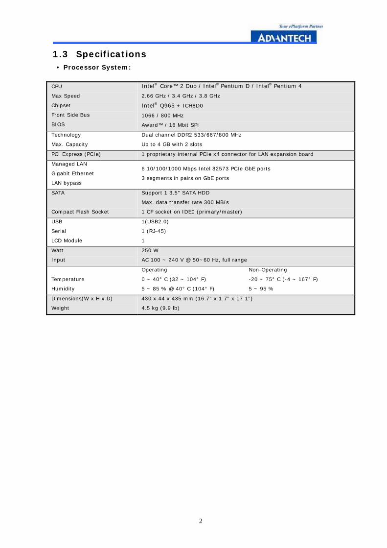
1.3 Specifications • Processor System:
CPU
Max Speed
Chipset
Front Side Bus
BIOS
Intel® Core™ 2 Duo / Intel® Pentium D / Intel® Pentium 4
2.66 GHz / 3.4 GHz / 3.8 GHz
Intel® Q965 + ICH8D0
1066 / 800 MHz
Award™ / 16 Mbit SPI
Technology
Max. Capacity
Dual channel DDR2 533/667/800 MHz
Up to 4 GB with 2 slots
PCI Express (PCIe) 1 proprietary internal PCIe x4 connector for LAN expansion board
Managed LAN
Gigabit Ethernet
LAN bypass
6 10/100/1000 Mbps Intel 82573 PCIe GbE ports
3 segments in pairs on GbE ports
SATA
Compact Flash Socket
Support 1 3.5” SATA HDD
Max. data transfer rate 300 MB/s
1 CF socket on IDE0 (primary/master)
USB
Serial
LCD Module
1(USB2.0)
1 (RJ-45)
1
Watt
Input
250 W
AC 100 ~ 240 V @ 50~60 Hz, full range
Temperature
Humidity
Operating
0 ~ 40° C (32 ~ 104° F)
5 ~ 85 % @ 40° C (104° F)
Non-Operating
-20 ~ 75° C (-4 ~ 167° F)
5 ~ 95 %
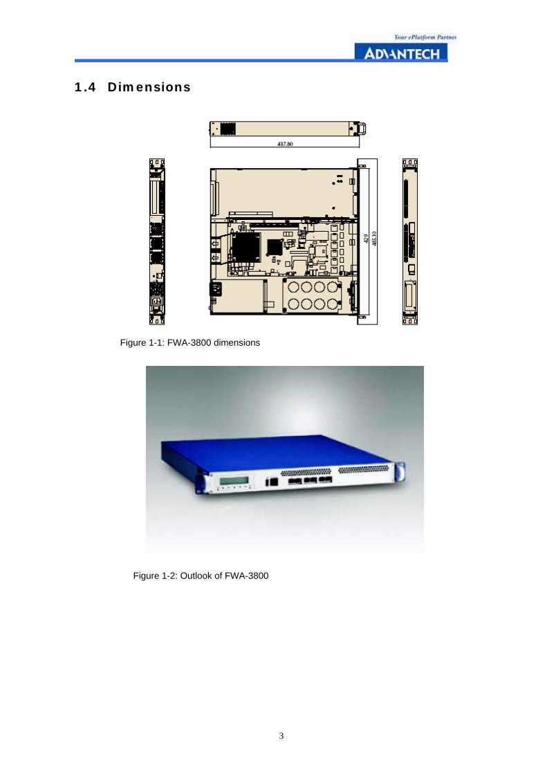
Dimensions(W x H x D)
Weight
430 x 44 x 435 mm (16.7” x 1.7” x 17.1”)
4.5 kg (9.9 lb)
3
1.4 Dimensions
Figure 1-1: FWA-3800 dimensions
Figure 1-2: Outlook of FWA-3800
4
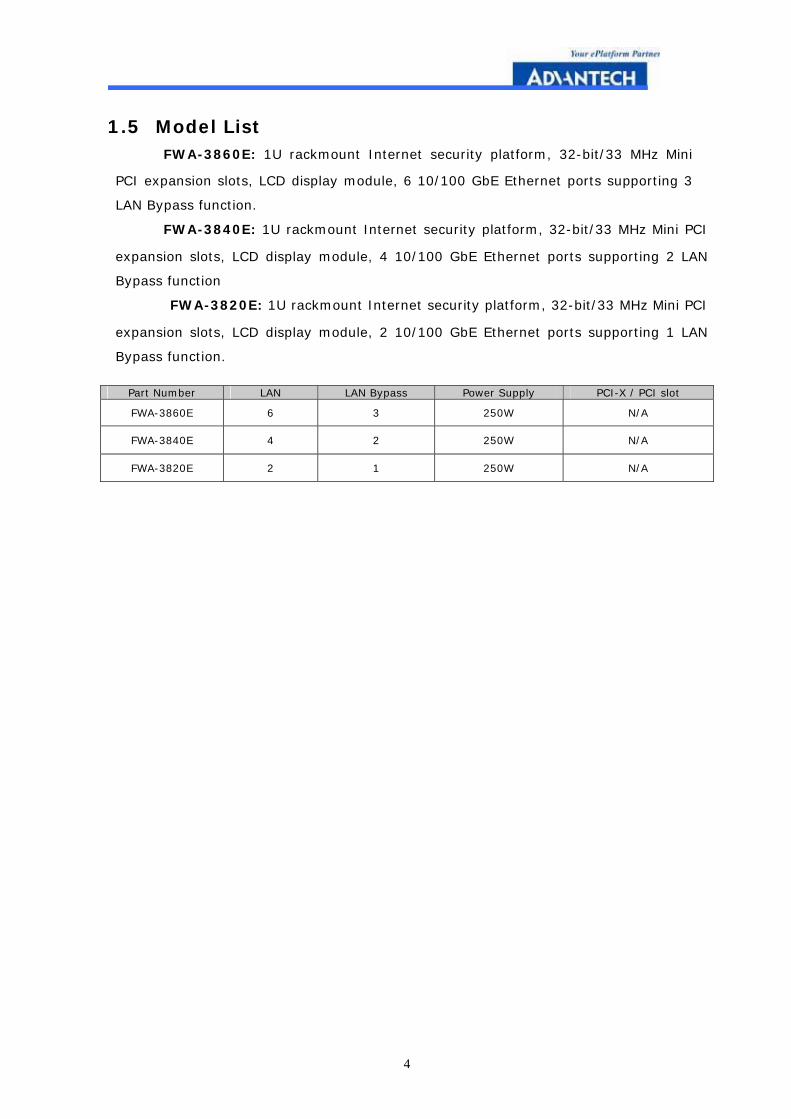
1.5 Model List � FWA-3860E: 1U rackmount Internet security platform, 32-bit/33 MHz Mini
PCI expansion slots, LCD display module, 6 10/100 GbE Ethernet ports supporting 3
LAN Bypass function.
� FWA-3840E: 1U rackmount Internet security platform, 32-bit/33 MHz Mini PCI
expansion slots, LCD display module, 4 10/100 GbE Ethernet ports supporting 2 LAN
Bypass function
� FWA-3820E: 1U rackmount Internet security platform, 32-bit/33 MHz Mini PCI
expansion slots, LCD display module, 2 10/100 GbE Ethernet ports supporting 1 LAN
Bypass function.
Part Number LAN LAN Bypass Power Supply PCI-X / PCI slot
FWA-3860E 6 3 250W N/A
FWA-3840E 4 2 250W N/A
FWA-3820E 2 1 250W N/A

5
2
2 SYSTEM SETUP
6
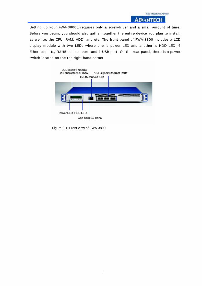
Setting up your FWA-3800E requires only a screwdriver and a small amount of time.
Before you begin, you should also gather together the entire device you plan to install,
as well as the CPU, RAM, HDD, and etc. The front panel of FWA-3800 includes a LCD
display module with two LEDs where one is power LED and another is HDD LED, 6
Ethernet ports, RJ-45 console port, and 1 USB port. On the rear panel, there is a power
switch located on the top right hand corner.
Figure 2-1: Front view of FWA-3800
7
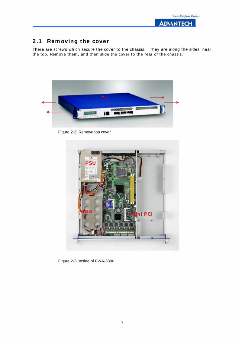
2.1 Removing the cover There are screws which secure the cover to the chassis. They are along the sides, near the top. Remove them, and then slide the cover to the rear of the chassis.
Figure 2-2: Remove top cover
Figure 2-3: Inside of FWA-3800
HDD Mini PCI
PSU
8
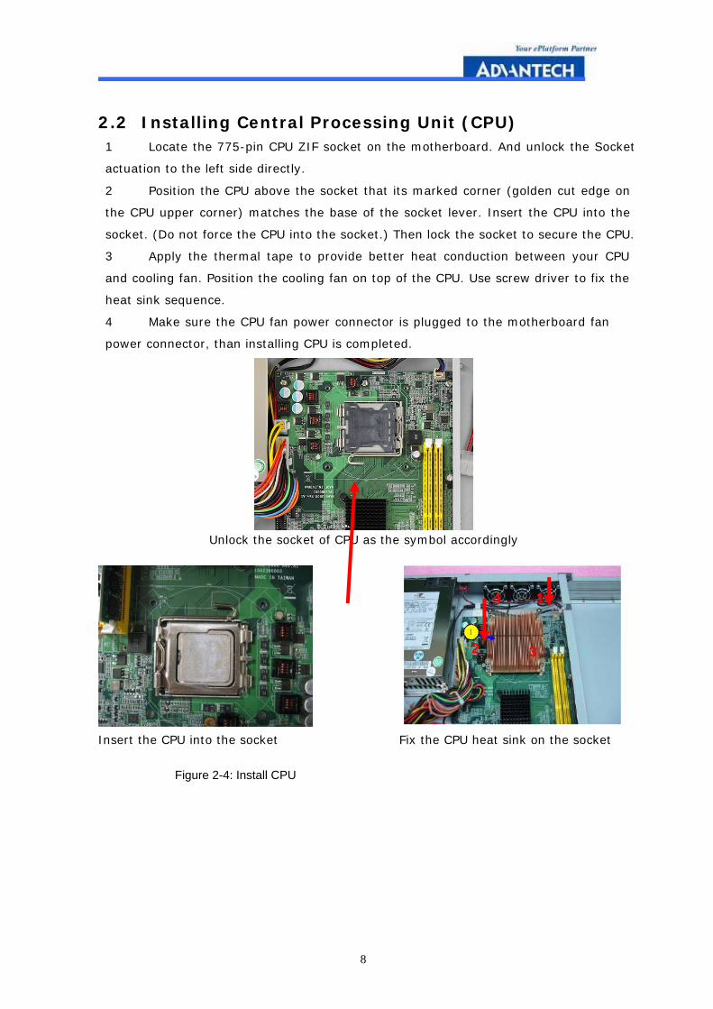
2.2 Installing Central Processing Unit (CPU) 1 Locate the 775-pin CPU ZIF socket on the motherboard. And unlock the Socket
actuation to the left side directly.
2 Position the CPU above the socket that its marked corner (golden cut edge on
the CPU upper corner) matches the base of the socket lever. Insert the CPU into the
socket. (Do not force the CPU into the socket.) Then lock the socket to secure the CPU.
3 Apply the thermal tape to provide better heat conduction between your CPU
and cooling fan. Position the cooling fan on top of the CPU. Use screw driver to fix the
heat sink sequence.
4 Make sure the CPU fan power connector is plugged to the motherboard fan
power connector, than installing CPU is completed.
Unlock the socket of CPU as the symbol accordingly
Insert the CPU into the socket Fix the CPU heat sink on the socket
Figure 2-4: Install CPU
4
3 2
1
9
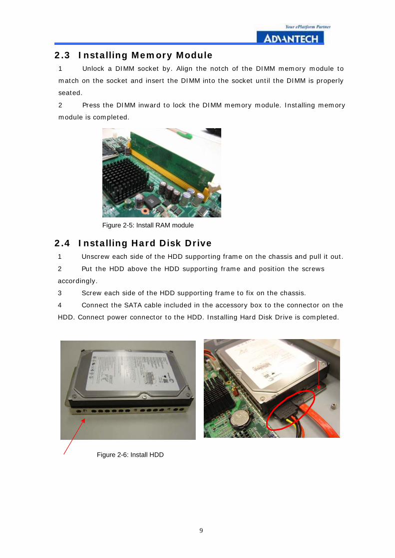
2.3 Installing Memory Module 1 Unlock a DIMM socket by. Align the notch of the DIMM memory module to
match on the socket and insert the DIMM into the socket until the DIMM is properly
seated.
2 Press the DIMM inward to lock the DIMM memory module. Installing memory
module is completed.
Figure 2-5: Install RAM module
2.4 Installing Hard Disk Drive 1 Unscrew each side of the HDD supporting frame on the chassis and pull it out.
2 Put the HDD above the HDD supporting frame and position the screws
accordingly.
3 Screw each side of the HDD supporting frame to fix on the chassis.
4 Connect the SATA cable included in the accessory box to the connector on the
HDD. Connect power connector to the HDD. Installing Hard Disk Drive is completed.
Figure 2-6: Install HDD
10
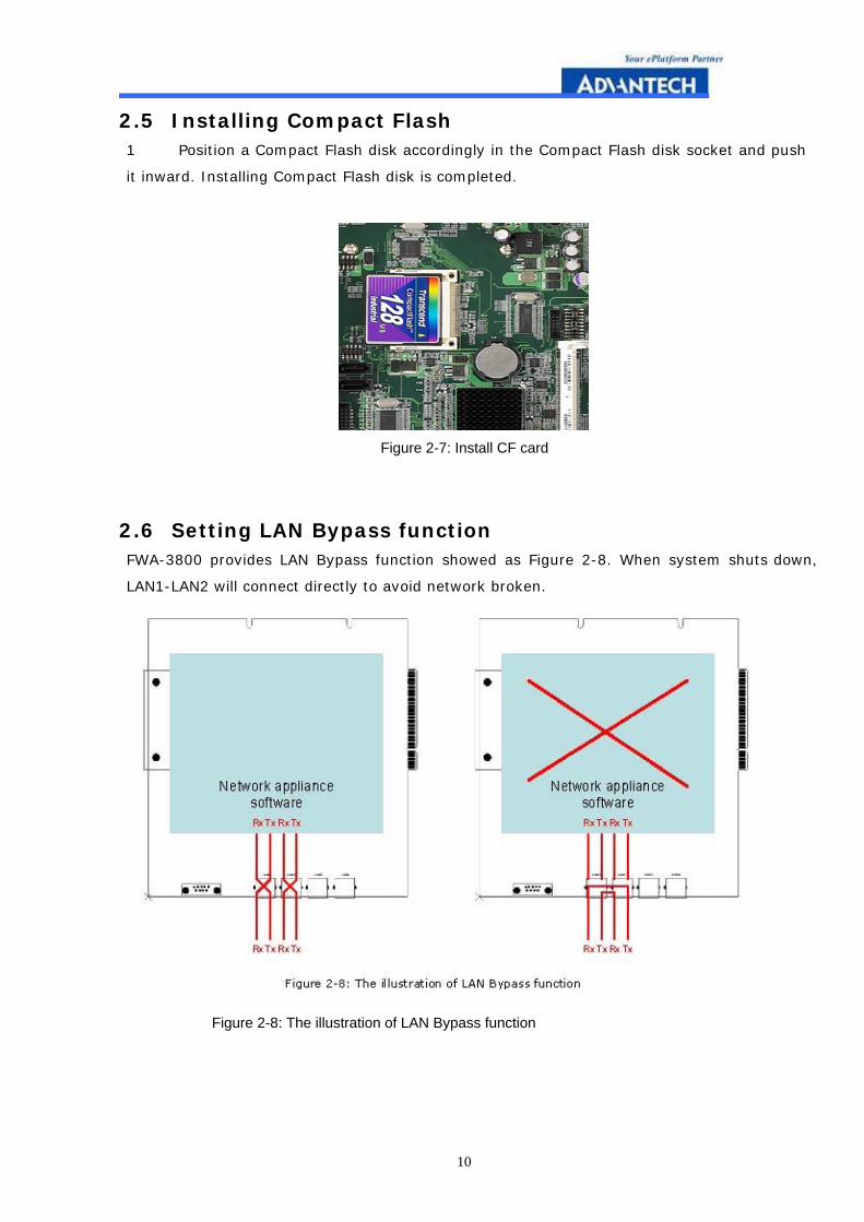
2.5 Installing Compact Flash 1 Position a Compact Flash disk accordingly in the Compact Flash disk socket and push
it inward. Installing Compact Flash disk is completed.
Figure 2-7: Install CF card
2.6 Setting LAN Bypass function FWA-3800 provides LAN Bypass function showed as Figure 2-8. When system shuts down,
LAN1-LAN2 will connect directly to avoid network broken.
Figure 2-8: The illustration of LAN Bypass function

11
1. Jumper Setting 1-3, 2-4 short, H/W Control
If PWR ON, LAN Bypass function disable ( All LANs Non-Bypass)
If PWR OFF, LAN Bypass function enable ( All LANs Bypass)
2. Jumper Setting 1-3, 4-6 short, BIOS (GPIO) Control
LAN 1/2 Bypass Ctrl LAN 3/4 Bypass Ctrl LAN 5/6 Bypass
Ctrl PWR OFF LAN Bypass Ctrl
Enable Enable Enable
PWR ON Bypass Bypass Bypass
PWR OFF Bypass Bypass Bypass
Enable
LAN 1/2 Bypass Ctrl LAN 3/4 Bypass Ctrl LAN 5/6 Bypass
Ctrl PWR OFF LAN Bypass Ctrl
Disable Disable Disable
PWR ON Non-Bypass Non-Bypass Non-Bypass
PWR OFF Bypass Bypass Bypass
Enable
LAN 1/2 Bypass Ctrl LAN 3/4 Bypass Ctrl LAN 5/6 Bypass
Ctrl PWR OFF LAN Bypass Ctrl
Enable Enable Enable
PWR ON Non-Bypass
( no connect) Non-Bypass
( no connect) Non-Bypass
( no connect)
PWR OFF Non-Bypass Non-Bypass Non-Bypass
Disable
LAN 1/2 Bypass Ctrl LAN 3/4 Bypass Ctrl LAN 5/6 Bypass
Ctrl PWR OFF LAN Bypass Ctrl
Disable Disable Disable
PWR ON Non-Bypass Non-Bypass Non-Bypass
PWR OFF Non-Bypass Non-Bypass Non-Bypass
Disable
.
12
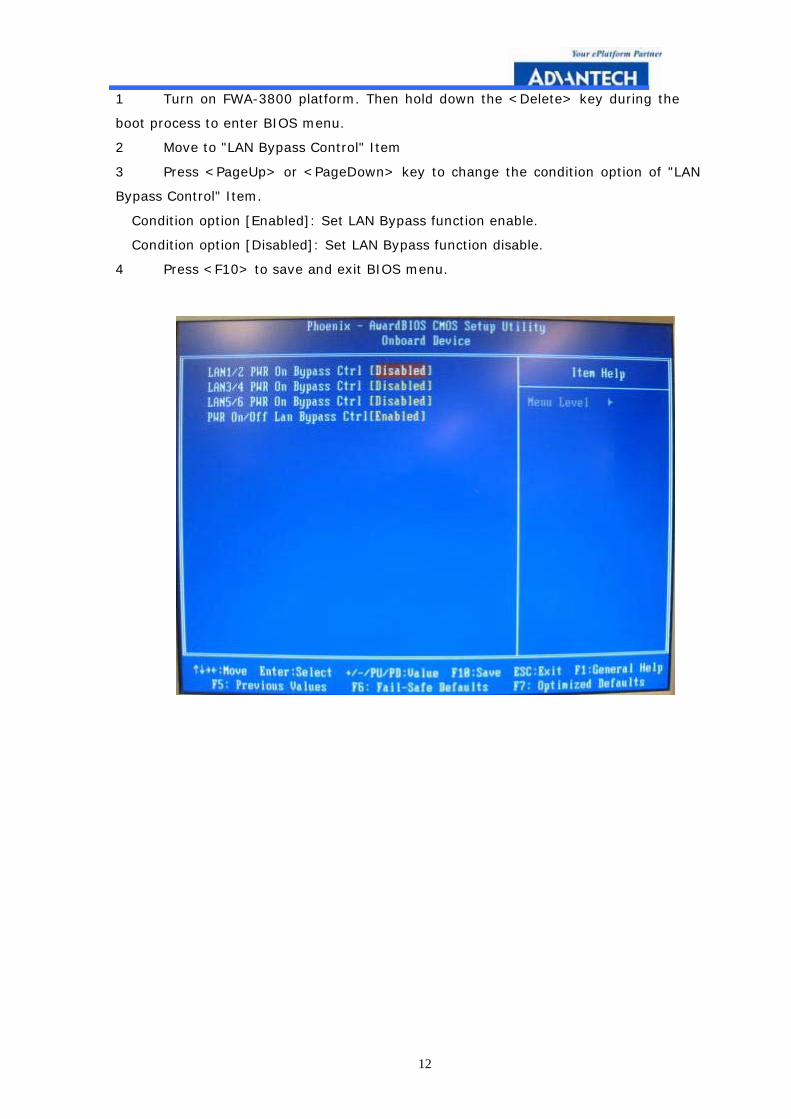
1 Turn on FWA-3800 platform. Then hold down the <Delete> key during the
boot process to enter BIOS menu.
2 Move to "LAN Bypass Control" Item
3 Press <PageUp> or <PageDown> key to change the condition option of "LAN
Bypass Control" Item.
Condition option [Enabled]: Set LAN Bypass function enable.
Condition option [Disabled]: Set LAN Bypass function disable.
4 Press <F10> to save and exit BIOS menu.

13
Appendix
Pin Assignments
14
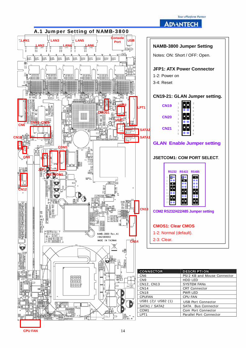
A.1 Jumper Setting of NAMB-3800
CONNECTOR DESCRIPTION CN6 PS/2 KB and Mouse Connector CN9 HDD LED CN12, CN13 SYSTEM FANs CN14 CRT Connector CN18 PWR LED CPUFAN CPU FAN USB1 (2)/ USB2 (1) USB Port Connector SATA1 / SATA2 SATA Bus Connector COM1 Com Port Connector LPT1 Parallel Port Connector
NAMB-3800 Jumper Setting
Notes: ON: Short / OFF: Open.
JFP1: ATX Power Connector 1-2: Power on 3-4: Reset
CN19-21: GLAN Jumper setting.
GLAN Enable Jumper setting
1
53CN19
CN20
CN21
64
2
53
1
53
1
2
64
64
2
JSETCOM1: COM PORT SELECT.
RS232 RS485
COM2 RS232/422/485 Jumper setting
RS422
753
1
17
1513119
CMOS1: Clear CMOS 1-2: Normal (default). 2-3: Clear.
LAN1 LAN2
LAN3 LAN4
LAN5 LAN6
Console Port USB
LPT1
SATA2
SATA1
USB2
USB1
CMOS1
CN6 CN19~CN21
COM1
JSETCOM1 JFP1
CN9
CN18
CN12
CN13
CN14
CPU FAN
Recommended