.
Model: FXO-HC32 SERIES
Page 1 of 24 FOXElectronics 5570 Enterprise Parkway Fort Myers, Florida 33905 USA +1.239.693.0099 FAX +1.239.693.1554 http://www.foxonline.com
EMEA Tel: +44 .1283.568153 | Canada +1.888.438.2369 | Japan Tel: +81.3.3374.2079 | Singapore Tel: +65.68447989© 2013 Fox Electronics | An Integrated Device Technology, Inc. company | ISO9001:2008 Certified
DWG-5053
HCMOS 3.2 x 2.5mm 2.5V Oscillator Freq: 0.75 MHz to 180MHzRev.3/27/2012
Features
XTREMELY Low Jitter
Low Cost
XPRESS Delivery
Frequency Resolution to six decimal places
Stabilities to ± 25 PPM
-20 to +70°C or -40 to +85°C operating temperatures
Tri-State Enable / Disable Feature
Industry Standard Package, Footprint & Pin-Out
Fully RoHS and REACH compliant
Gold over Nickel Termination Finish
Serial ID with Comprehensive Traceability
Applications ANY application requiring an oscillator
SONET
Ethernet
Storage Area Network
Broadband Access
Microprocessors / DSP / FPGA
Industrial Controllers
Test and Measurement Equipment
Fiber Channel
Contents page
Model Selection & Part Number Guide 2 Electrical Characteristics 3 Absolute Maximums 4 Output Wave Characteristics 4 Phase Noise 5 Jitter 5 Pin Assignment 6 Recommended Circuit 6 Reflow 6 Mechanical Drawing and Pad Layout 7 Tape and Reel Specification 8 Label 8 Traceability – LOT Number & Serial Identification 9 SGS Report 10~13 REACH Report 14~21 Mechanical Test 22 Burn-In Test 22 MTTF / FITS calculations 23 Other XPRESSO Links 24 Fox Contact Information 24
Description The Fox XPRESSO Crystal Oscillator is a breakthrough in configurable Frequency Control Solutions. XPRESSO utilizes a family of proprietary ASICs, designed and developed by Fox, with a key focus on noise reduction technologies. The 3rd order Delta Sigma Modulator reduces noise to the levels that are comparable to traditional Bulk Quartz and SAW oscillators. The ASICs family has ability to select the output type, input voltages, and temperature performance features. With the XPRESS lead-time, low cost, low noise, wide frequency range, excellent ambient performance, XpressO is an excellent choice over the conventional technologies. Finished XPRESSO parts are 100% final tested.
OUTPUT
Enable / DisableV
GND
DD
For more information -- Click on the drawing
PRESSXFOX
ASICsO
This part is no longer available from Fox, please contact IDT for this product.

FXO-HC32 Series
Page 2 of 24 © 2012 FOX ELECTRONICS | ISO9001:2008 Certified
DWG-5053
This example, FXO-HC325R-106.25 = HCMOS Output, Ceramic 3.2 x 2.5mm Package, 2.5V, ±50 PPM Stability, -40 to +85°C Temperature Range, at 106.25 MHz
Model Selection Guide & Fox Part Number
766A – 1 0 6 . 2 5 – 8 The 1st Field Product Code # 766A = FXO–HC32 766 = FXO–HC33
The 2nd Field The Customer’s Frequency
The 3rd Field Fox Internally Generated Number (If any specification changes, the last digits change) (The same specs for a different customer also changes the last digits)
STEP #2: The Fox Customer Service team provides a customer specific Part Numberfor use on their Bill Of Materials (BOM).
Fox Part Number (The assigned Fox Part Number must be on the BOM – not the above Model Description)(This will ensure receipt of the proper part)
H = HCMOS
L = LVDS
P = LVPECL
M = LVDS (pin 2 E/D)
Q = LVPECL (pin 2 E/D)
X = HCMOS (comp 2nd Output)
0 = ± 100 PPM
5 = ± 50 PPM 6 = ± 25 PPM (-20 ~ +70°C)
3 = 3.2 x 2.5mm5 = 5 x 3.2mm
7 = 7 x 5mm
C = Ceramic
Q = Quartz
blank = -20°C to +70°C
R = -40°C to +85°C
3 = 3.3 V
2 = 2.5 V
F X O – H C 3 2 5 R – 1 0 6 . 2 5 Frequency (in MHz) Resolutions to 6 places
past the decimal point
STEP #1: Customer selects the Model Description and provides to Fox Customer Service Model Description
This part is no longer available from Fox, please contact IDT for this product.

FXO-HC32 Series
Page 3 of 24 © 2012 FOX ELECTRONICS | ISO9001:2008 Certified
DWG-5053
Electrical Characteristics
Parameters Symbol Condition Maximum Value
(unless otherwise noted)
Frequency Range FO 0.750 to 180.000 MHz
Frequency Stability 1-20 ~ +70°C-40 to +85°C
100, 50, 25* PPM 100, 50 PPM
Temperature Range TO
TSTG
Standard operating Optional operating
Storage
-20°C to +70°C-40°C to +85°C
-55°C to +125°C Supply Voltage VDD Standard 2.5 V ± 5%
Input Current (@ 15pF LOAD) IDD
0.75 ~ 20 MHz 20+ ~ 50 MHz
50+ ~ 100 MHz 100+ ~ 130 MHz 130+ ~ 160 MHz 160+ ~ 180 MHz
22 mA 25 mA 29 mA 32 mA 35 mA 37 mA
Output Load HCMOS Standard 15 pF
Start-Up Time TS 10 mS
Output Enable / Disable Time 100 nS
Moisture Sensitivity Level MSL JEDEC J-STD-20 1 Termination Finish Au
1Inclusive of 25°C tolerance, operating temperature range, input voltage change, load change, aging, shock and vibration. *Excludes aging.
Absolute Maximum Ratings (Useful life may be impaired. For user guidelines only, not tested)
Operation is only guaranteed for voltage and temperature specifications in Electrical Characteristics section.)
Parameters Symbol Condition Maximum Value
(unless otherwise noted)
Input Voltage VDD –0.5V to +5.0V
Operating Temperature TAMAX –55°C to +105°C
Storage Temperature TSTG –55°C to +125°C
Junction Temperature 125°CESD Sensitivity HBM Human Body Model > 1 kV
This part is no longer available from Fox, please contact IDT for this product.
FXO-HC32 Series
Page 4 of 24 © 2012 FOX ELECTRONICS | ISO9001:2008 Certified
DWG-5053
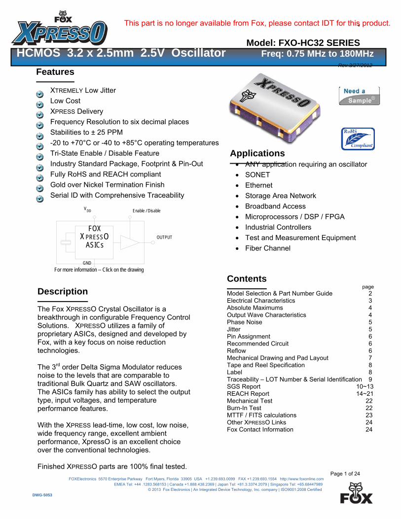
If 30% to 70% times are used, Rise and Fall times change to 2 nS from 0.75 to 180MHz If 20% to 80% times are used, Rise and Fall times change to 2.5 nS from 0.75 to 160MHz
Output Wave Characteristics
Parameters
Symbol
Condition Maximum Value
(unless otherwise noted)
Output LOW Voltage VOL 0.75 to 160 MHz 160+ to 180 MHz
10% VDD 20% VDD
Output HIGH Voltage VOH 0.75 to 160 MHz 160+ to 180 MHz
90% VDD MIN 80% VDD MIN
Output Symmetry (See Drawing Below) @ 50% VDD Level 45% ~ 55%
Output Enable (PIN # 1) Voltage VIH ≥ 70% VDD
Output Disable (PIN # 1) Voltage VIL ≤ 30% VDD
Cycle Rise Time (See Drawing Below) TR 0.75 to 160 MHz 160+ to 180 MHz
3.5 nS (10%~90%) 2.5 nS (20%~80%)
Cycle Fall Time (See Drawing Below) TF
0.75 to 160 MHz 160+ to 180 MHz
3.5 nS (90%~10%) 2.5 nS (80%~20%)
20% to 80%
10% to 90%
0V to V
Rise Time
10% - 90% 90% - 10%
Fall Time Times
80 - 20
50% V
On Time Off Time1/2 Period
Period
Ideally, Symmetry should be 50/50 -- Other expressions are 45/55 or 55/45
1/2 Period
Rise Time / Fall Time Measurements
Oscillator Symmetry
70 - 30
Times
30% to 70%
DD
DD
This part is no longer available from Fox, please contact IDT for this product.
FXO-HC32 Series
Page 5 of 24 © 2012 FOX ELECTRONICS | ISO9001:2008 Certified
DWG-5053
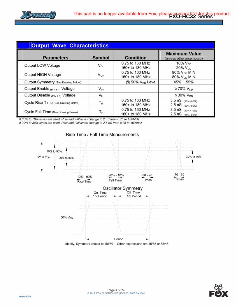
62.5MHz
106.25MHz
125MHz
156.25MHz
-160
-140
-120
-100
-80
-60
-40
-20
0
10 100 1000 10000 100000 1000000 10000000 100000000
dB
c
Data Collected using HP 3048AFour Frequencies from Jitter Tables62.5MHz only to 2MHz offset due to Equipment Limitation
Jitter is frequency dependent. Below are typical values at select frequencies.
Phase Jitter is integrated from HP3048 Phase Noise Measurement System; measured directly into 50 ohm input; VDD = 2.5V. TIE was measured on LeCroy LC684 Digital Storage Scope, directly into 50 ohm input, with Amherst M1 software; VDD = 2.5V.
Per MJSQ spec (Methodologies for Jitter and Signal Quality specifications)
Rj and Dj, measured on LeCroy LC684 Digital Storage Scope, directly into 50 ohm input, with Amherst M1 software.Per MJSQ spec (Methodologies for Jitter and Signal Quality specifications)
Phase Jitter & Time Interval Error (TIE)
Frequency Phase Jitter
(12kHz to 20MHz)T I E
(Sigma of Jitter Distribution)
Units
62.5 MHz 0.9 2.9 pS RMS
106.25 MHz 0.8 3.5 pS RMS
125 MHz 0.8 2.5 pS RMS 156.25 MHz 0.9 3.1 pS RMS
Random & Deterministic Jitter Composition
Frequency Random (Rj)
(pS RMS) Deterministic (Dj)
(pS P-P)Total Jitter (Tj)
(14 x Rj) + Dj
62.5 MHz 1.3 9.2 28.4 pS
106.25 MHz 1.3 9.0 27.2 pS
125 MHz 1.3 8.8 27.7 pS 156.25 MHz 1.4 10.4 30.3 pS
Phase Noise
2.5V Phase Noise Graphs (dBc/Hz vs. offset frequency
This part is no longer available from Fox, please contact IDT for this product.
FXO-HC32 Series
Page 6 of 24 © 2012 FOX ELECTRONICS | ISO9001:2008 Certified
DWG-5053
NOTE: XPRESSO HCMOS XOs are designed to fit on Industry Standard, 4 pad layouts
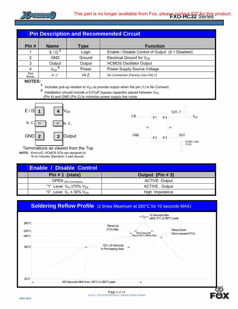
Pin Description and Recommended Circuit
Pin #
Name
Type
Function
1 E / D 1 Logic Enable / Disable Control of Output (0 = Disabled)
2 GND Ground Electrical Ground for VDD
3 Output Output HCMOS Oscillator Output
4 VDD 2 Power Power Supply Source Voltage
Test Points N. C. Hi Z No Connection (Factory Use ONLY)
NOTES: 1 Includes pull-up resistor to VDD to provide output when the pin (1) is No Connect.
2 Installation should include a 0.01µF bypass capacitor placed between VDD (Pin 4) and GND (Pin 2) to minimize power supply line noise.
E / D VDD
N. C. N. C.
GND Output
Terminations as viewed from the Top
Enable / Disable Control Pin # 1 (state) Output (Pin # 3) OPEN (No Connection) ACTIVE Output
“1” Level VIH ≥70% VDD ACTIVE Output
“0” Level VIL ≤ 30% VDD High Impedance
2
TP
1
3
4
TP
Soldering Reflow Profile (2 times Maximum at 260°C for 10 seconds MAX)
25°C
160°C
180°C
225°C
260°C
10 Seconds Maxwithin 5°C of 260°C peak
Ramp DownNot to exceed 6°C/s
Ramp-Up3°C/s Max
pt
120 ± 20 SecondsIn Pre-heating Area
Above 225°C Reflow Area50±10 Seconds
400 Seconds MAX from +25°C to 260°C peak
GND
E/D
HCMOS LOAD(15 pF)
N C
# 4
# 3# 2
# 1
OUT
0.01 F
DDV
N C
This part is no longer available from Fox, please contact IDT for this product.

FXO-HC32 Series
Page 7 of 24 © 2012 FOX ELECTRONICS | ISO9001:2008 Certified
DWG-5053
Mechanical Dimensional Drawing & Pad Layout
Actual part marking is depicted.
See Traceability (pg. 8)
for more information
Drawing is for reference to critical specifications defined by size measurements. Certain non-critical visual attributes, such as side castellations, reference pin shape, etc. may vary
# 1 E / D
# 2 GND
# 3 Output
# 4 VDD
Pin Connections
1 2
34 TPNC
TPNC
Side View
Bottom View
End View1 2
34
3.2 x 2.5 XpressO
3.3 Max
2.6 Max
1.0 Max
0.35
1.0 Max
0.90
0.50
0.90
0.70
HCMOS
1.00
1.40
1.20
0.50
TPNC
TPNC
RecommendedSolder Pad Layout
1
Note: XpressO HCMOS XO's are designed to fit on industry standard, 4 pad layouts.
XPRESSO
This part is no longer available from Fox, please contact IDT for this product.
FXO-HC32 Series
Page 8 of 24 © 2012 FOX ELECTRONICS | ISO9001:2008 Certified
DWG-5053
Ø1.5mm4.0mm
4.0mm
3.5mm8.0mm
1.4mm
Ø22.0
2.5
Ø13.0
9.0
60.2178.0
1.75
An additional identification code is contained internally if tracking should ever be necessary
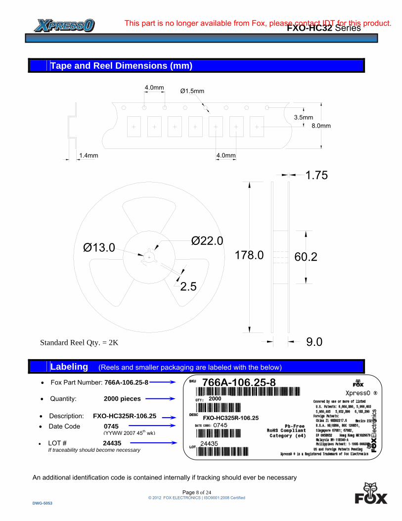
Tape and Reel Dimensions (mm)
Labeling (Reels and smaller packaging are labeled with the below)
Fox Part Number: 766A-106.25-8
Quantity: 2000 pieces
LOT # 24435 If traceability should become necessary
Description: FXO-HC325R-106.25
Date Code 0745 (YYWW 2007 45th wk)
FXO-HC325R-106.25
766A-106.25-8
Standard Reel Qty. = 2K
2000
This part is no longer available from Fox, please contact IDT for this product.
FXO-HC32 Series
Page 9 of 24 © 2012 FOX ELECTRONICS | ISO9001:2008 Certified
DWG-5053
LOT Number The LOT Number has direct ties to the customer purchase order. The LOT Number is marked on the “Reel” label, and also stored internally on non-volatile memory inside the XPRESSO part. XPRESSO parts that are shipped Tape and Reel, are also placed in an Electro Static Discharge (ESD) bag and will have the LOT Number labeled on the exterior of the ESD bag. It is recommended that the XPRESSO parts remain in this ESD bag during storage for protection and identification. If the parts become separated from the label showing the LOT Number, it can be retrieved from inside one of the parts, and the information that can be obtained is listed below:
Customer Purchase Order Number Internal Fox Sales Order Number Dates that the XPRESSO part was shipped from the factory The assigned customer part number The specification that the part was designed for
Serial Identification The Serial ID is the individualized information about the configuration of that particular XPRESSO part. The Serial ID is unique for each and every XPRESSO part, and can be read by special Fox equipment. With the Serial ID, the below information can be obtained about that individual, XPRESSO part:
Equipment that the XPRESSO part was configured on Raw material used to configure the XPRESSO part Traceability of the raw material back to the foundries manufacturing lot Date and Time that the part was configured Any optimized electrical parameters based on customer specifications Electrical testing of the actual completed part Human resource that was monitoring the configuration of the part
Fox has equipment placed at key Fox locations World Wide to read the Lot Identification and Serial Number of any XPRESSO part produced and can then obtain the information from above within 24 hours.
Traceability – LOT Number & Serial Identification
This part is no longer available from Fox, please contact IDT for this product.
FXO-HC32 Series
Page 10 of 24 © 2012 FOX ELECTRONICS | ISO9001:2008 Certified
DWG-5053
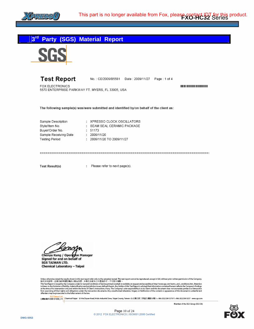
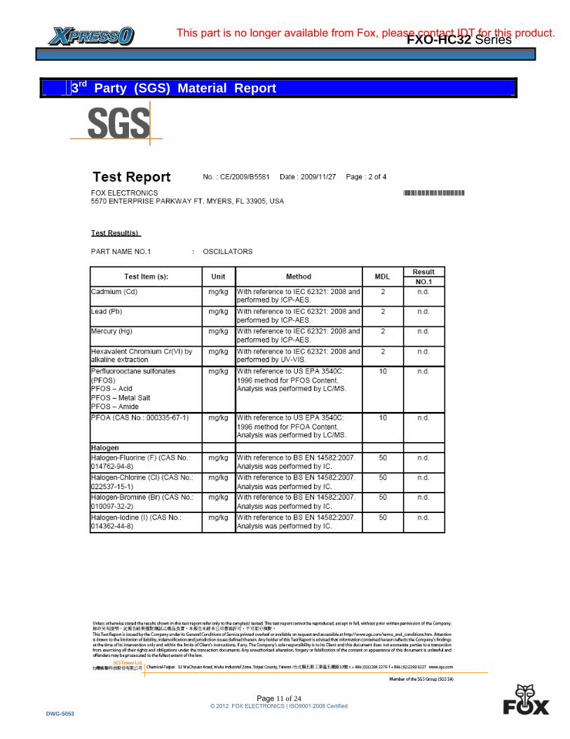
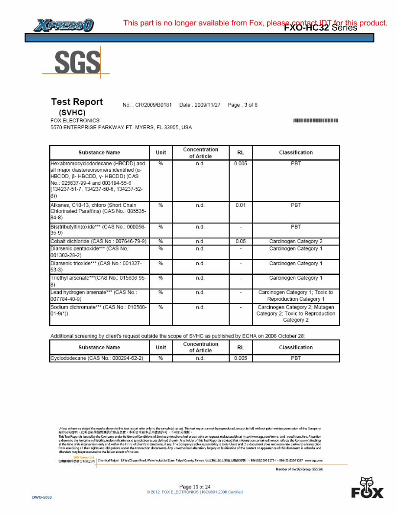
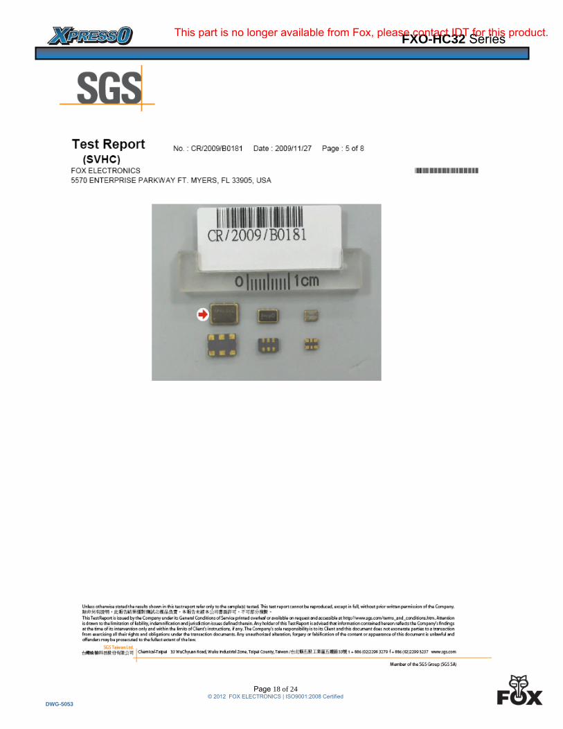
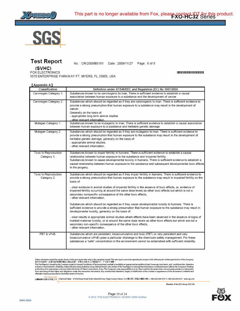
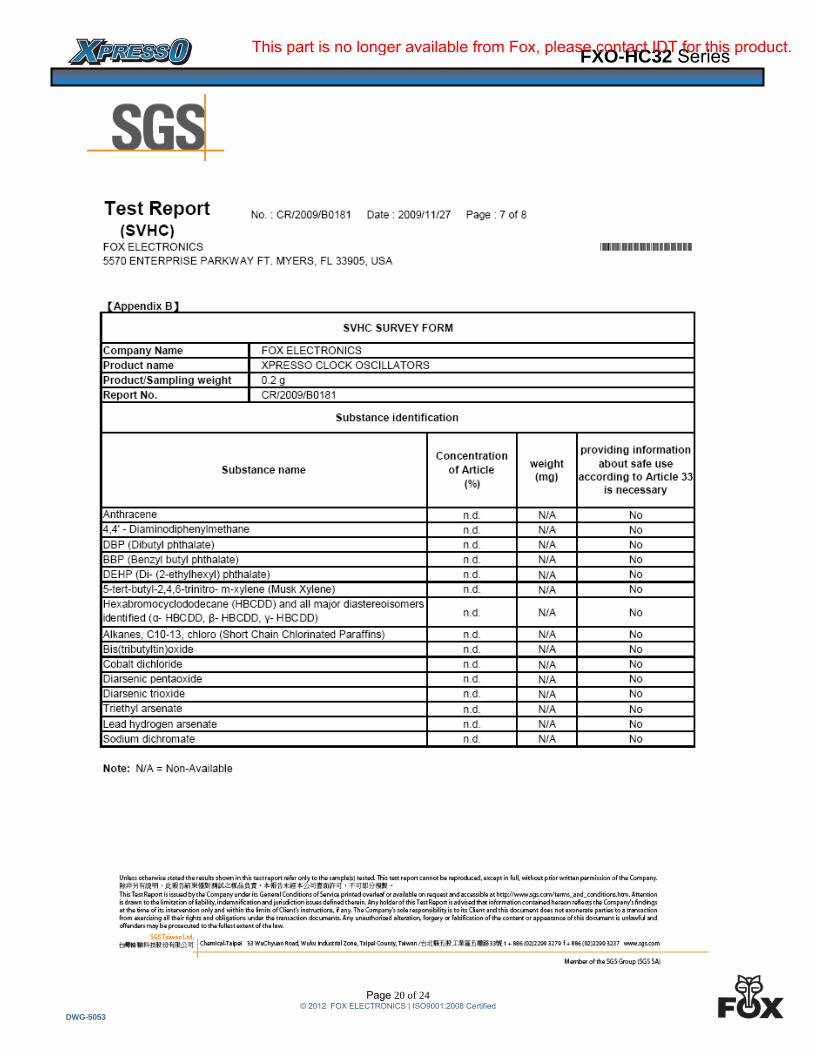
3rd Party (SGS) Material Report
This part is no longer available from Fox, please contact IDT for this product.
FXO-HC32 Series
Page 11 of 24 © 2012 FOX ELECTRONICS | ISO9001:2008 Certified
DWG-5053
3rd Party (SGS) Material Report
This part is no longer available from Fox, please contact IDT for this product.
FXO-HC32 Series
Page 12 of 24 © 2012 FOX ELECTRONICS | ISO9001:2008 Certified
DWG-5053
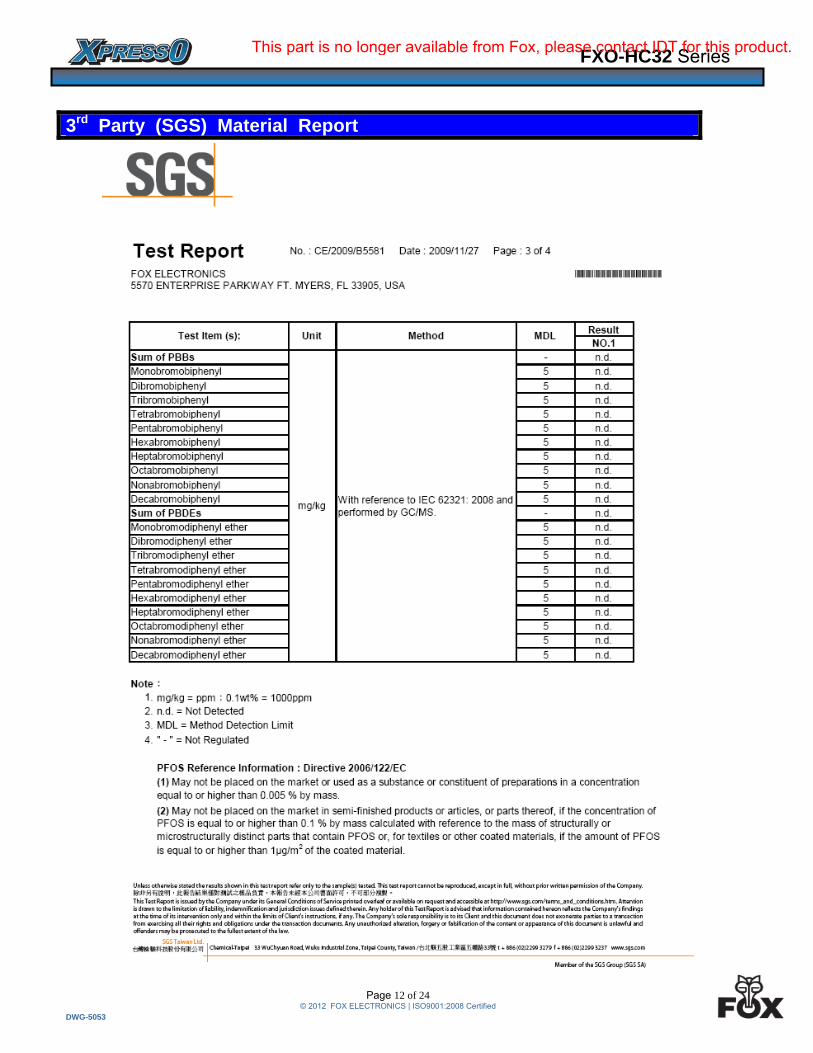
3rd Party (SGS) Material Report
This part is no longer available from Fox, please contact IDT for this product.
FXO-HC32 Series
Page 13 of 24 © 2012 FOX ELECTRONICS | ISO9001:2008 Certified
DWG-5053
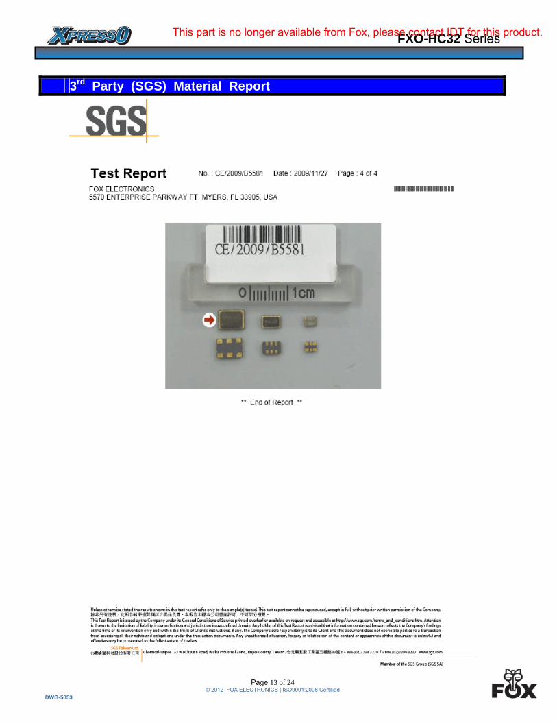
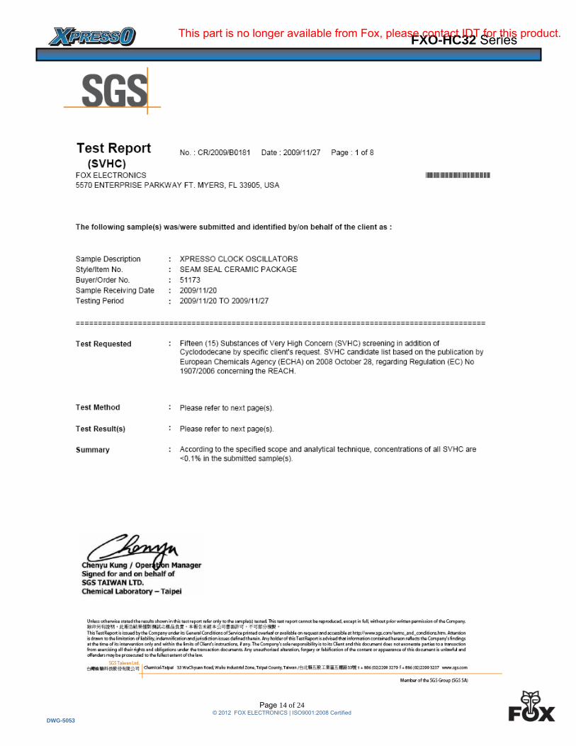
3rd Party (SGS) Material Report
This part is no longer available from Fox, please contact IDT for this product.
FXO-HC32 Series
Page 14 of 24 © 2012 FOX ELECTRONICS | ISO9001:2008 Certified
DWG-5053
This part is no longer available from Fox, please contact IDT for this product.

FXO-HC32 Series
Page 15 of 24 © 2012 FOX ELECTRONICS | ISO9001:2008 Certified
DWG-5053
This part is no longer available from Fox, please contact IDT for this product.
FXO-HC32 Series
Page 16 of 24 © 2012 FOX ELECTRONICS | ISO9001:2008 Certified
DWG-5053
This part is no longer available from Fox, please contact IDT for this product.

FXO-HC32 Series
Page 17 of 24 © 2012 FOX ELECTRONICS | ISO9001:2008 Certified
DWG-5053
This part is no longer available from Fox, please contact IDT for this product.
FXO-HC32 Series
Page 18 of 24 © 2012 FOX ELECTRONICS | ISO9001:2008 Certified
DWG-5053
This part is no longer available from Fox, please contact IDT for this product.
FXO-HC32 Series
Page 19 of 24 © 2012 FOX ELECTRONICS | ISO9001:2008 Certified
DWG-5053
This part is no longer available from Fox, please contact IDT for this product.
FXO-HC32 Series
Page 20 of 24 © 2012 FOX ELECTRONICS | ISO9001:2008 Certified
DWG-5053
This part is no longer available from Fox, please contact IDT for this product.

FXO-HC32 Series
Page 21 of 24 © 2012 FOX ELECTRONICS | ISO9001:2008 Certified
DWG-5053
This part is no longer available from Fox, please contact IDT for this product.

FXO-HC32 Series
Page 22 of 24 © 2012 FOX ELECTRONICS | ISO9001:2008 Certified
DWG-5053
Burn-In Testing – under power 2000 Hours, 125°C
XpressO HCMOS Burn-In (Power on) Freq = 10MHz, N = 120
-10
-5
0
5
10
Initial 250 hours 500 hours 1000hours
2000hours
Fre
qu
en
cy
Dri
ft (
PP
M)
Mechanical Testing
Parameter Test Method Mechanical Shock Drop from 75cm to hardwood surface – 3 times
Mechanical Vibration 10~55Hz, 1.5mm amplitude, 1 Minute Sweep
2 Hours each in 3 Directions (X, Y, Z)
High Temperature Burn-in Under Power @ 125°C for 2000 Hours (results below)
Hermetic Seal He pressure: 4 ±1 kgf / cm2 2 Hour soak
2,000 Hour Burn-In
This part is no longer available from Fox, please contact IDT for this product.
FXO-HC32 Series
Page 23 of 24 © 2012 FOX ELECTRONICS | ISO9001:2008 Certified
DWG-5053
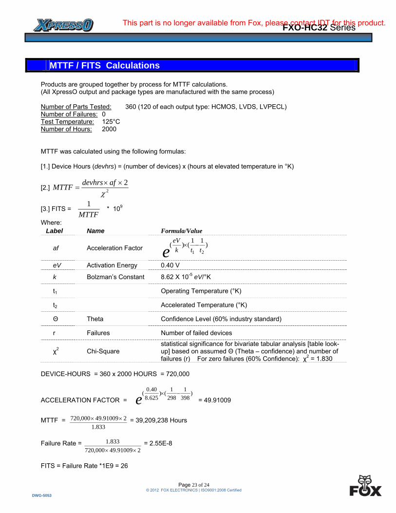
Products are grouped together by process for MTTF calculations. (All XpressO output and package types are manufactured with the same process)
Number of Parts Tested: 360 (120 of each output type: HCMOS, LVDS, LVPECL) Number of Failures: 0 Test Temperature: 125°C Number of Hours: 2000 MTTF was calculated using the following formulas: [1.] Device Hours (devhrs) = (number of devices) x (hours at elevated temperature in °K)
[2.] 2
2
afdevhrs
MTTF
[3.] FITS = MTTF
1 * 109
Where: Label Name Formula/Value
af Acceleration Factor e ttk
eV)
11()(
21
eV Activation Energy 0.40 V
k Bolzman’s Constant 8.62 X 10⁻⁵ eV/°K
t1 Operating Temperature (°K)
t2 Accelerated Temperature (°K)
Θ Theta Confidence Level (60% industry standard)
r Failures Number of failed devices
χ2 Chi-Square statistical significance for bivariate tabular analysis [table look-up] based on assumed Θ (Theta – confidence) and number of failures (r) For zero failures (60% Confidence): χ2 = 1.830
DEVICE-HOURS = 360 x 2000 HOURS = 720,000
ACCELERATION FACTOR = e)
398
1
298
1()
625.8
40.0(
= 49.91009
MTTF = 833.1
291009.49000,720 = 39,209,238 Hours
Failure Rate = 291009.49000,720
833.1
= 2.55E-8
FITS = Failure Rate *1E9 = 26
MTTF / FITS Calculations
This part is no longer available from Fox, please contact IDT for this product.
FXO-HC32 Series
Page 24 of 24 © 2012 FOX ELECTRONICS | ISO9001:2008 Certified
DWG-5053
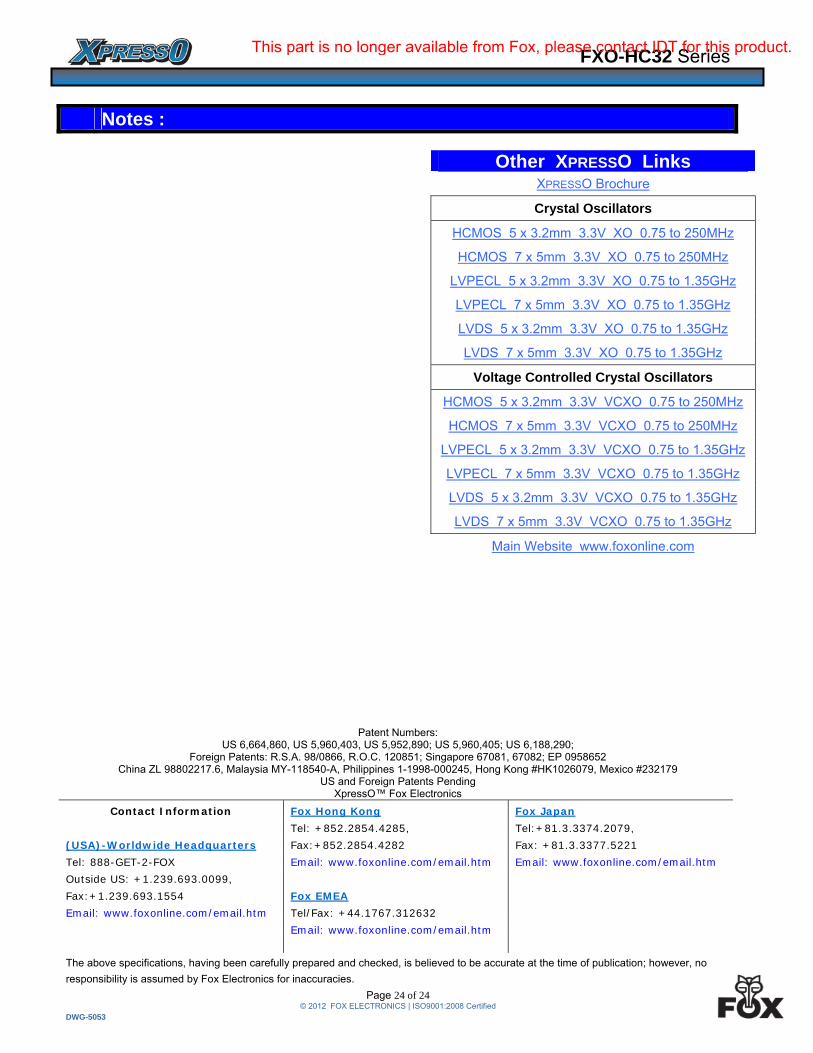
Other XPRESSO Links XPRESSO Brochure
Crystal Oscillators
HCMOS 5 x 3.2mm 3.3V XO 0.75 to 250MHz
HCMOS 7 x 5mm 3.3V XO 0.75 to 250MHz
LVPECL 5 x 3.2mm 3.3V XO 0.75 to 1.35GHz
LVPECL 7 x 5mm 3.3V XO 0.75 to 1.35GHz
LVDS 5 x 3.2mm 3.3V XO 0.75 to 1.35GHz
LVDS 7 x 5mm 3.3V XO 0.75 to 1.35GHz
Voltage Controlled Crystal Oscillators
HCMOS 5 x 3.2mm 3.3V VCXO 0.75 to 250MHz
HCMOS 7 x 5mm 3.3V VCXO 0.75 to 250MHz
LVPECL 5 x 3.2mm 3.3V VCXO 0.75 to 1.35GHz
LVPECL 7 x 5mm 3.3V VCXO 0.75 to 1.35GHz
LVDS 5 x 3.2mm 3.3V VCXO 0.75 to 1.35GHz
LVDS 7 x 5mm 3.3V VCXO 0.75 to 1.35GHz
Main Website www.foxonline.com
Patent Numbers: US 6,664,860, US 5,960,403, US 5,952,890; US 5,960,405; US 6,188,290;
Foreign Patents: R.S.A. 98/0866, R.O.C. 120851; Singapore 67081, 67082; EP 0958652 China ZL 98802217.6, Malaysia MY-118540-A, Philippines 1-1998-000245, Hong Kong #HK1026079, Mexico #232179
US and Foreign Patents Pending XpressO™ Fox Electronics
Contact Information Fox Hong Kong Fox Japan Tel: +852.2854.4285, Tel:+81.3.3374.2079, (USA)-Worldwide Headquarters Fax:+852.2854.4282 Fax: +81.3.3377.5221 Tel: 888-GET-2-FOX Email: www.foxonline.com/email.htm Email: www.foxonline.com/email.htm Outside US: +1.239.693.0099, Fax:+1.239.693.1554 Fox EMEA Email: www.foxonline.com/email.htm Tel/Fax: +44.1767.312632 Email: www.foxonline.com/email.htm The above specifications, having been carefully prepared and checked, is believed to be accurate at the time of publication; however, no
responsibility is assumed by Fox Electronics for inaccuracies.
Notes :
This part is no longer available from Fox, please contact IDT for this product.
Recommended