IPS-G-PI-230
This Standard is the property of Iranian Ministry of Petroleum. All rights are reserved to the owner. Neither whole nor any part of this document may be disclosed to any third party, reproduced, stored in any retrieval system or transmitted in any form or by any means without the prior written consent of the Iranian Ministry of Petroleum.
GENERAL STANDARD
FOR
STRAINERS AND FILTERS
ORIGINAL EDITION
JULY 1997
This standard specification is reviewed and updated by the relevant technical committee on Jul. 2001. The approved modifications are included in the present issue of IPS.

Jul. 1997
IPS-G-PI-230
1
CONTENTS : PAGE No.
1. SCOPE ............................................................................................................................................ 3 2. REFERENCES ................................................................................................................................ 3 3. DEFINITIONS AND TERMINOLOGY ............................................................................................. 4
3.1 Strainer..................................................................................................................................... 4 3.2 Filter.......................................................................................................................................... 4 3.3 Inspector .................................................................................................................................. 4
4. UNITS .............................................................................................................................................. 4 5. GENERAL REQUIREMENTS ......................................................................................................... 4 6. STRAINER AND FILTER DESIGN, FABRICATION AND ASSEMBLY ........................................ 5 7. MATERIAL AND DIMENSIONS ..................................................................................................... 6 8. TYPES OF STRAINERS ................................................................................................................. 7
8.1 Flat Type Strainer.................................................................................................................... 7 8.2 Conical Type Strainer ............................................................................................................. 7 8.3 "T" Type Strainer..................................................................................................................... 7 8.4 "Y" Type Strainer .................................................................................................................... 7 8.5 Basket Type Strainer .............................................................................................................. 7 8.6 Dual Strainer ............................................................................................................................ 7 8.7 Self Cleaning Strainer............................................................................................................. 7 8.8 Oil Burner Strainer .................................................................................................................. 8
9. INSPECTION................................................................................................................................... 9 9.1 Normal Inspection................................................................................................................... 9 9.2 Additional Inspection.............................................................................................................. 9
10. TESTS ........................................................................................................................................... 9 10.1 General ................................................................................................................................... 9 10.2 Deformation and External Leakage (Tightening Test) .................................................... 10 10.3 Pressure Drop Test of Strainers or Filters for Oil Burners............................................. 10 10.4 Clogging Test of Strainers for Oil Burners ...................................................................... 10 10.5 Mercurous Nitrate Immersion Test.................................................................................... 10 10.6 Fire and Thermal Shock Test ............................................................................................. 10 10.7 Vibration Test ...................................................................................................................... 10 10.8 Shock Test ........................................................................................................................... 10 10.9 Cold-Temperature Test....................................................................................................... 10 10.10 Hydrostatic-Strength Test ................................................................................................ 10
11. RESPONSIBILITIES ................................................................................................................... 10 12. PAINTING AND PROTECTION.................................................................................................. 11 13. IDENTIFICATION AND MARKING............................................................................................. 11 14. PACKING AND SHIPMENT ....................................................................................................... 11 15. GUARANTEE.............................................................................................................................. 12 16. INSURANCE ............................................................................................................................... 12 17. DATA SUPPLIED........................................................................................................................ 12 TABLES: TABLE 1 - MESH SIZE AND ELEMENT MATERIAL FOR PUMP SUCTION STRAINERS........... 13
Jul. 1997
IPS-G-PI-230
2
TABLE 2 - MESH SIZE AND ELEMENT MATERIAL FOR COMPRESSOR SUCTION STRAINERS........................................................................................................................................................... 13 TABLE 3 - MESH SIZE AND ELEMENT MATERIAL FOR TURBINE SUCTION STRAINERS ..... 14 TABLE 4 - DIMENSIONS FOR SCREEN AND PERFORATED PLATE OPENING ....................... 14 FIGURES: Fig. 1 PUMP SUCTION FILTER ....................................................................................................... 15 Fig. 2 ‘T’ LINE STRAINER ............................................................................................................... 16 Fig. 3 FILTER DETAIL...................................................................................................................... 17 Fig. 4. BASKET TYPE STRAINER .................................................................................................. 18 Fig. 5 DUALL IN-LINE STRAINER (SCHEMATIC) ......................................................................... 18 Fig. 6 SELF-CLEANING STRAINERS ............................................................................................. 19 Fig. 7 AUTOMATIC SELF-CLEANING STRAINER......................................................................... 19 Fig. 8 TYPICAL PARTS OF "Y" TYPE STRAINER......................................................................... 20 Fig. 9 STRAINER AREA FOR* No. 1 FUEL OIL ............................................................................. 21 Fig. 10 STRAINER AREA FOR* No. 2 FUEL OIL ........................................................................... 21 Fig. 11 STRAINER AREA FOR* NOS. 4, 5, 6 FUEL OIL ................................................................ 22

Jul. 1997
IPS-G-PI-230
3
1. SCOPE
This Standard covers general requirements for design material, fabrication, inspection and test of different types of strainers and filters mainly used in suction lines of pumps, compressors and turbines in Iranian Oil, Gas and Petrochemical Industries.
This Standard is intended to supplement purchase orders placed for strainers and filters. If requirements of this Standard differ from, or is in conflict with purchase documents, the following will take precedence in the order of priority as indicated hereunder:
a) Purchase order,
b) Data sheets and drawings,
c) This Standard specifications.
Note:
This standard specification is reviewed and updated by the relevant technical committee on Jul. 2001. The approved modifications by T.C. were sent to IPS users as amendment No. 1 by circular No 142 on Jul. 2001. These modifications are included in the present issue of IPS.
2. REFERENCES
Throughout this Standard the following dated and undated standards/codes are referred to. These referenced documents shall, to the extent specified herein, form a part of this standard. For dated references, the edition cited applies. The applicability of changes in dated references that occur after the cited date shall be mutually agreed upon by the Company and the Vendor. For undated references, the latest edition of the referenced documents (including any supplements and amendments) applies.
IPS (IRANIAN PETROLEUM STANDARDS)
IPS-E-TP-100 "Paints"
IPS-M-PI-150 "Flanges and Fittings"
IPS DRAWINGS(IRANIAN PETROLEUM STANDARD DRAWINGS)
IPS-D-PI-113 ("Y" Type Suction Strainers)
IPS-D-PI-114 ("T" Type Suction Strainers)
IPS-D-PI-116 "Flat Type Suction Strainers"
IPS-D-PI-117 "Conical Type Suction Strainers"
IPS-D-PI-118 "Bayonet Filters for Compressor Suction Lines"
ISO (INTERNATIONAL ORGANIZATION FOR STANDARDIZATION)
ISO 7-1.1982 "Pipe Threads Where Pressure-Tight Joints Are Made on the Threads"
ISO 148 "Charpy Impact Test (V Notch)"
ASTM (AMERICAN SOCIETY FOR TESTING AND MATERIALS)
ASTM A-370 "Test Method and Definitions for Mechanical Testing of Steel Products"

Jul. 1997
IPS-G-PI-230
4
ASTM E-125-1985 "Reference Photographs for Magnetic Particle Indication on Ferrous Casting"
ASTM E-142-1986 "Method for Controlling Quality of Radiographic Testing"
ASTM E-165-1983 "Practice for Liquid Penetrant Inspection Method"
ASTM E-186-1984 "Reference Radiographs for Heavy Walled Steel Casting"
ASTM E-446-1984 "Referenced Radiographs for Steel Casting up to 51 mm (2") in Thickness"
ANSI (AMERICAN NATIONAL STANDARD INSTITUTE)
ANSI B-16.34-1988 "Valves-Flanged, Threaded, and Welding Ends"
ANSI B-31.3 "Chemical Plant and Petroleum Refinery Piping"
UL (UNDERWRITERS LABORATORIES)
ANSI/UL 331 (1977) "Strainers for Flammable Fluids and Anhydrous Ammonia"
ANSI/UL 1105 (1977) "Marine Use Filters, Strainers and Separators"
ANSI/UL 1193 (1985) "Marine Filters and Strainers for Non-Flammable Liquids"
SIS (STANDARDISERINGS KOMISSIONEN I SVERIGE)
SIS 05 5900 "Swedish Standards Institution Practice Surface Preparation Standard for Painting Steel Surface"
ASME (AMERICAN SOCIETY FOR MECHANICAL ENGINEERS)
ASME Section VIII Div I
3. DEFINITIONS AND TERMINOLOGY
3.1 Strainer
A device designed to separate particles, that are 150 microns or more in size, from fluids.
3.2 Filter
A device designed to remove particle size 500 down to one micron, from fluids.
3.3 Inspector
The representative of the Company who is entrusted with inspection of products, production records, production facilities and quality control tests.
4. UNITS
International System of Units (SI) in accordance with IPS-E-GN-100 shall be used.
5. GENERAL REQUIREMENTS
Jul. 1997
IPS-G-PI-230
5
5.1 Filters shall be a horizontal or vertical vessel with a full end quick opening closures and shall be designed, constructed and inspected in accordance with ASME Requirement for Pressure Vessels, Section VIII, Div. 1.
5.2 The supplier shall complete all performance data as indicated on the filters and strainers data sheet.
5.3 Differential pressure protection device such as differential pressure indicator, alarm and trip shall be provided for each filter and strainer as specified in data sheet, and shall be positioned so that the pressure drop across the filter or strainer element can be determined. This pressure drop shall not exceed 0.5% of the flowing line pressure, if not specified on the data sheet.
5.4 Pressure tight covers or flanged access opening shall be provided to permit internal access for inspection, maintenance and filter or strainer element replacement.
5.5 Flange or other type of connections shall match the line class and rating for which it is intended.
5.6 Maintenance servicing shall be possible without the necessity for breaking pipe connection. Internals shall be able to be changed out within ten minutes once the vessel has been drained and head cover removed.
5.7 The filter element of a cartridge filter shall be designed as a disposable component, to be replaced with a new cartridge when clogged. Some cartridge elements of Robust Construction may be specified as cleanable and re-usable.
5.8 Cartridge filters shall be compact, reliable, easy to operate.
5.9 Cartridge filters shall be used in systems where the contaminant level are less than 0.01% by weight (100 ppm).
5.10 Different materials as cited in Clause 7.12 may be used for cartridge element.
5.11 All air filters shall be designed to be installed upright directly onto the compressor, blower or engine inlet or on the remote inlet to air intake piping.
5.12 Filters and strainers shall be designed so that standard elements available from various sources may be used.
5.13 Filter inlet design shall include provision to prevent direct impingement of the incoming fluid onto the filter element (Fig. 1).
5.14 Air dryer filters shall be cartridge type, cleanable and suitable for oil and vapor removal. When desiccants are used, other filters shall be suitable for removal of desiccant particles.
5.15 For compressor suction lines bayonet filters as shown in IPS-D-PI-118 should be used.
6. STRAINER AND FILTER DESIGN, FABRICATION AND ASSEMBLY
6.1 Permanent strainers should normally be of a design having a steel body incorporating a basket which can be removed without dismantling pipework.
6.2 Strainers shall be so designed and fabricated to prevent their damage due to vibration, differential pressure, pulsating flow, or impact of objects.
6.3 Screen of mesh size 20 or finer shall be reinforced with perforated plate, or heavier screen and steel bars.
6.4 Strainer open area shall be not less than three times the inlet pipe cross-section area. For suction lines to compressors in air service, this criteria shall be followed unless otherwise specified.
6.5 Cone or basket type strainers shall be provided with identification tabs that protrude from the holding pipe flanges.
6.6 In "TEE" type strainers, guide rods and shelf rods supporting the strainer element shall be sized as per standard drawing IPS-D-PI-114.
6.7 End flanges of strainers shall be integral with the body. Only for steel strainers, the flanges may

Jul. 1997
IPS-G-PI-230
6
be added by full penetration butt-welding.
6.8 Strainer bodies shall have an arrow raised on the body itself, indicating the direction of flow.
6.9 The construction of a strainer or filter shall be such that parts can be reassembled in the intended manner after being dismantled to the extent needed for servicing.
6.10 A strainer or filter shall be constructed so that, when in its intended operating position, any air trapped within will not reduce the rate of liquid flow or the effective strainer element capacity.
6.11 A unit element shall be constructed to hold in its intended position to ensure that joints or seals required to prevent fluid bypass of the element will be maintained.
6.12 A strainer shall be such that, when the screen or filter element is removed for cleaning, all foreign matter (sediment and dirt) will be removed or can be removed without the probability of any foreign matter being deposited in the outlet side of the strainer.
6.13 In each strainer, or filter clean-out and drain openings shall be closed by a standard pipe plug or a threaded shouldered plug. The plugs shall not create a galvanic cell with the housing that will accelerate corrosion.
6.14 Both external and internal parts of the assembly shall be free of rough or sharp edges that are likely to cause injury to persons servicing the unit.
6.15 The assembly shall be capable of disassembly and reassembly with ordinary tools.
6.16 The assembly shall be constructed to withstand the stresses and strains likely to be encountered in service.
6.17 An opening threaded for conncetion of pipe shall be threaded in accordance with the Standard for Pipe Threads, ISO 7-1.1982.
6.18 Strainers provided with screwed covers shall employ either ground joints gaskets, or "O" rings suitable for the purpose. If gasket or "O" ring is used, it shall be retained by the body, cover, or cap when the part is removed and shall not be damaged when the cover or cap is screwed in place.
6.19 Cementing or retaining of the gasket is not necessary provided a complete set of new gaskets is furnished with each replacement cartridge for those filters employing a cartridge-type filtering element.
6.20 Body and cover joint shall be clamped or flanged as specified in the fabrication design of strainer. This joint shall be suitable to meet the rating conditions required.
7. MATERIAL AND DIMENSIONS
7.1 The material for strainer or filter body (including bolting) shall be equal to the materials of valves in the same service.
7.2 In general the screen for factory fabricated strainers shall be basket type made of the same (or better) materials as the valve trim of the line classes, e.g., 11 to 13 percent chrome or Type 316 stainless steel.
7.3 If corrosion of a ferrous part will interfere with the intended function of a strainer or filter, the part shall be provided with a corrosion resistant protective coating.
7.4 A protective coating shall provide resistance against corrosion to a degree not less than that provided by the protective plating specified in Paragraph 7.5.
7.5 Cadmium plating shall have a thickness of not less than 0.008 mm (0.0003 inch) and zinc plating shall have a thickness of not less than 0.013 mm (0.0005 inch), except on parts where threads constitute the major portion of the area, in which case the thickness of the cadmium or zinc plating shall be not less than 0.0038 mm (0.00015 inch).
7.6 Wire cloth type elements, if finer than 60 mesh, shall be resistant to corrosion. A 60 mesh or coarser element shall be resistant to the fluid it may normally contact.
7.7 A part made of drawn brass or machined from brass rod shall be capable of withstanding,

Jul. 1997
IPS-G-PI-230
7
without cracking, a mercurous nitrate test for copper and copper alloys.
7.8 The mesh size and material of suction pump strainers shall be in accordance with Table 1.
7.9 The mesh size and material for strainer elements used in compressor systems shall be in accordance with Table 2.
7.10 The mesh size and material for strainer elements used in turbine systems shall be in accordance with Table 3.
7.11 For the dimension of screen and perforated plate opening refer to Table 4.
7.12 Many different types of filter media should be available for separating solid matter from liquids and gases; the range may include paper, natural and synthetic fibres felt, plastic sheet, ceramic, carbon, cotton, yarn, cloth, woven wire, woven fabric, organic and inorganic membranes, perforated metal, sintered metals and many other materials.
8. TYPES OF STRAINERS
Different types of suction strainers are as follow:
8.1 Flat Type Strainer
Flat disc strainer shall be in form of perforated plate and shall be used as a temporary strainer in suction lines. Its size and characteristics are shown in IPS-D-PI-116.
8.2 Conical Type Strainer
This kind of strainers shall be used as temporary strainers in suction lines and is shown in IPS-D-PI-117.
8.3 "T" Type Strainer
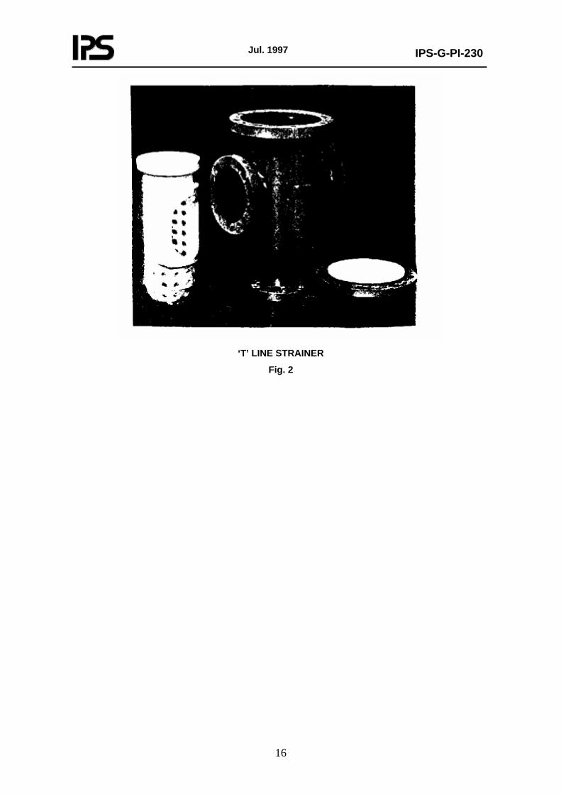
This type strainer with bathtub screen shall be used as temporary or permanent strainers and is shown in detail in IPS-D-PI-114. Other versions of T type strainer are illustrated in Figs. 2 & 3.
8.4 "Y" Type Strainer
This kind of strainers shall be required for permanent installation in vertical or horizontal suction lines, and is shown with detail in IPS-D-PI-113.
8.5 Basket Type Strainer
On large pipelines basket type strainers shall be used (Fig. 4). They shall provide greater dirt holding capacity and easier access for removal of the strainer for cleaning. They normally have a higher pressure drop than simple Y type strainer.
8.6 Dual Strainer
Where continuous operation is required in a pipeline service, dual strainers shall be used in an integral unit with provision to isolate them at any time for cleaning (Fig. 5).
8.7 Self Cleaning Strainer
8.7.1 This type of strainers shall be used as an alternative to dual or multiple strainers where continuous supply is critical in process system and shall be divided into brush model and screw

Jul. 1997
IPS-G-PI-230
8
model as illustrated in (Fig. 6).
8.7.2 Twin strainers or self cleaning strainers, as appropriate, shall be used in unspared equipment services.
8.7.3 Self cleaning strainers shall be provided with valved blowdown connections.
8.7.4 If considerable clogging of strainers is anticipated due to coke or similar conditions (as indicated on the data sheet), strainer shall be of the Automatic Self-cleaning type to permit continuous flow of clean liquid (Fig. 7).
8.8 Oil Burner Strainer
8.8.1 Each strainer assembly intended for use with oil burning equipment is to be rated for capacity in terms of the maximum firing rate of the burner equipment as expressed in terms of litre of fuel oil per hour (0.264 gallons/hr). Figs. 9 to 11 provide for strainers employing wire cloth or perforated screens, minimum areas of screen opening based upon the grade of fuel oil used, and the size of the equipment to be served.
8.8.2 Strainer capacity ratings for oil burner strainers are expressed in terms of maximum burner firing capacity rather than actual flow capacity. The curves as shown in Figs. 9 to 11 have been predicated on experience and are designed to provide freedom from excessive strainer for a reasonable periode of time.
8.8.3 The selection of capacity ratings based on Firing Rates versus Open or Free Area for various grades of fuel oil also provides for low initial pressure losses or dorps through the strainer assembly when clean.
8.8.4 The capacity of each size and type of element is to be determined. When possible, this is to be accomplished by calculation as outlined in Paragraphs 8.8.5 and 8.8.6 for wire cloth and perforated types. Elements other than these, such as filter elements of felt, cotton waste, ceramics, and the like, are to be subjected to the tests in Sections 10.5 and 10.6 to establish ratings by comparison to the recognized properties of wire cloth or perforated screens.
8.8.5 A wire cloth type element has an open area equal to the total area of the cloth minus the area covered by wrap woof, and supports multiplied by the screen factor. The screen factor is that percentage of open area of the cloth to the whole area. If the screen factor is unknown, it may be calculated as follows:
Screen factor = (1-ND) × (1-nd)
Where:
N = Number of wires in warp per unit length
n = Number of wires in the woof per unit length
D = Diameter of wire in warp in mm
d = Diameter of wire in the woof in mm
8.8.6 A perforated type element has an open area equal to the total number of openings multiplied by the area of each opening minus the area covered by seams, ribs, and supports.
8.8.7 The effective area of a perforated type element which includes a wire cloth insert is considered to be the smaller of the two areas determined by Paragraphs 8.8.5 and 8.8.6.
8.8.8 A filter type element when clean, other than the wire cloth or perforated type (i.e., filter elements such as felt, cotton waste, or ceramics), shall not cause a pressure differential between inlet and outlet openings in excess of 51.8 mm of mercury (approximately 6.9 kPa or 1 psi) when passing the intended grade of fuel oil at a rate not exceeding the rated capacity of the strainer.

Jul. 1997
IPS-G-PI-230
9
9. INSPECTION
9.1 Normal Inspection
Manufacturer should be prepared for inspection of strainer/filter. The inspection shall include the followings:
a) Check of chemical and mechanical properties of the materials used.
b) Visual inspection of parts and casing.
c) Dimentional inspection.
d) Assembly inspection.
9.2 Additional Inspection
Additional inspection shall be carried out unless otherwise specified in the purchase order. These additional inspections are listed below.
9.2.1 Radiographic examination of welding of flanges to the body of steel strainers or filters:
- Weld quality shall conform to requirements of ANSI B.31.3 with regards to the butt-welded flanges.
9.2.2 Radiographic examination of body of strainers:
- Radiographic examination shall be made in areas shown in Fig. 8 (i.e., zones 1, 2 and 3).
- The radiographic procedure and criteria for acceptability of defects indicated in radiographs shall be in accordance with ANSI B.16.34, Annex B.
- The Types and degrees of discontinuities in radiographs and also the use of film and recording media can be compared with those cited in ASTM E- 142, E-186 and E-446.
9.2.3 Magnetic-particle examination of the whole surface of body of strainers and filters:
- Inspection procedure and degree of acceptability shall comply with requirements laid down in ANSI B.16.34, Annex C. Type and classification of defects shall be compared with reference photographs of ASTM E-125.
9.2.4 Liquid Penetrant Inspection
This type of inspection shall be used in lieu of magnetic examination where this examination is not applicable. The inspection method shall conform to ASTM E-165. The procedure and acceptance standard shall comply with requirements outlined in ANSI B.16-34, Annex D.
9.2.5 Charpy impact test on strainers and filters (V-notch)
Charpy impact test shall be performed for toughness indication. The test shall be performed in accordance with ASTM A 370 and ISO 148.
10. TESTS
10.1 General
10.1.1 Except as otherwise indicated, representative samples of a filter or strainer are to be subjected to the tests described in this Standard.
10.1.2 If a series of strainer or filter is to be investigated in which the bodies differ in size only, three

Jul. 1997
IPS-G-PI-230
10
representative samples are to be chosen to include the largest, smallest, and one intermediate size. If a strainer or filter having a single body size is being investigated, one sample is sufficient.
10.1.3 Strainer or filter is to be investigated for a specific fluid or fluids and for the service conditions for which it is to be recommended, such as fluid temperature and fluid pressure.
10.2 Deformation and External Leakage (Tightening Test)
This test shall be performed according to clause 11 of ANSI/UL 331 (1977).
10.3 Pressure Drop Test of Strainers or Filters for Oil Burners
This test shall be carried out according to clause 14 of ANSI/UL 331 (1977).
10.4 Clogging Test of Strainers for Oil Burners
Clogging test shall be performed according to clause 15 of ANSI/UL 331 (1977).
10.5 Mercurous Nitrate Immersion Test
Mercurous nitrate immersion test shall be carried out according to Clause 16 of ANSI/UL 331 (1977).
10.6 Fire and Thermal Shock Test
This test shall be done in accordance with clause 16 of ANSI/UL 1105 (1977).
10.7 Vibration Test
Vibration test according to clause 12 of ANSI/UL 1105 shall be applied if specified by the Engineer.
10.8 Shock Test
Shock test shall be applied to strainers if specified by the Engineer according to ANSI/UL 1105 (1977).
10.9 Cold-Temperature Test
Cold temperature test according to ANSI/UL 1193 (1985) shall be performed on strainers and filters, if they are used in areas which temperature falls down to -30°C. After this test, shock test according to clause 10-8 shall be performed.
10.10 Hydrostatic-Strength Test
This test shall be done in accordance with clause 12. Of UL 331 (1977)
11. RESPONSIBILITIES
Testing performed in the presence of purchaser’s representative shall not relieve the manufacturers of their own responsibilities and guarantees and any further contractual obligations.

Jul. 1997
IPS-G-PI-230
11
12. PAINTING AND PROTECTION
12.1 On completion of tests all strainers and filters shall be painted with two layers of antirust undercoat and one final layer of paint suitable for the specified environment following surface preparation to sa 2½ of Swedish Standard. The color of final layer shall be as per IPS-E-TP-100.
12.2 Stainless steel or bronze strainers or filters shall not be painted.
12.3 All unpainted surfaces (inside or outside) shall be adequately protected with suitable antirust compound, easily removable by hydrocarbon solvent.
12.4 Flanged or butt-welded ends shall be protected with wooden covers of a diameter not less than the outside diameter of the ends. Screwed and socket-welding ends shall be protected with plastic or carboard plugs.
13. IDENTIFICATION AND MARKING
13.1 Corrosion-resistants stainless steel nameplate shall be securely fastened by screws or rivets to each identifiable piece of equipment.
13.2 The following information shall be embossed on nameplate:
a) Manufacturer’s name;
b) manufacturer’s serial number;
c) date of manufacture;
d) equipment item or tag number;
e) size (nominal diameter of connecting pipe and face to face dimension);
f) weight including internals;
g) whether or not radiographed and/or stress relieved;
h) pressure rating;
i) body and element material;
j) Hydrostatic Test Pressure
13.3 A strainer or filter shall be also marked with the following information:
a) The fluid service or services for which the strainer or filter is intend ed.
b) The direction of flow.
c) In oil burner strainers or filters, the rated effective area or the catalog designation of the element, or equivalent, if more than one size element is available for a particular strainer or filter. This marking shall be on the element.
d) Marking shall be legible and reasonably permanent, such as afforded by a metal nameplate, decalcomania transfer, or waterproof marking ink.
e) If a manufacturer produces strainers or filters at more than one factory, each strainer or filter shall have a distinctive marking to identify it as the product of a particular factory.
14. PACKING AND SHIPMENT
14.1 Strainers or filters shall be suitably packed for export and protected against all damages or defects which may occur during handling, sea shipment to the port and rough road haulage to site and extended tropical open air storage, generally as per purchaser’s general condition of purchase.
14.2 Spare parts shall be packed for long time storage under site atmospheric condition as cited in the data sheet.

Jul. 1997
IPS-G-PI-230
12
15. GUARANTEE
15.1 All equipment and component parts shall be guaranteed by vendor against defective material, design and workmanship when operated under normal condition for 12 months starting from the completion of seven days continuous test "in situ" at full load, but not exceeding 18 months after date of shipment. If any malperformance or defects occur during the guarantee period, vendor shall make available repaired, altered or replacement parts free of any charges, whatsoever, direct on the purchasers job site. Vendor shall make available free of charge qualified representatives as he deems necessary to superwise the removal, repair and replacement of the defective parts in such a manner that the guarantee be maintained.
15.2 The guarantee period for repaired or replaced parts shall be 12 months after start up of repaired equipment but not more than 18 months after the repaired parts and/or equipment are shipped.
15.3 The guarantee period for the reamining equipment whose operation is dependent upon the proper performance of the repaired part shall be extended by the number of days or fraction thereof that the equipment have been inoperative because of defects. Field labor charges for work during the guarantee period shall be subject to negotiation between purchaser and Vendor.
15.4 If defects are found and vendor is not in position to take necessary action and perform the repairs, within the time required by purchaser and agreed upon every time according to purchaser requirements, purchaser shall have such modification and repairs made and the relevant expense will be charged to Vendor. It is understood that in this instance vendor shall not be relieved of his guarantee and contract obligations.
15.5 Furthermore Vendor shall guarantee the provision of spare parts for a minimum period of 15 years from the late date of dispatch of the materials and/or equipment.
16. INSURANCE
Supplier shall be noticed of any insurance facilities and rates in case where the safety of the strainers and filters to be shipped or boarded deemed essential.
17. DATA SUPPLIED
The manufacturer/supplier’s proposal shall include the following information:
17.1 Preliminary outline drawings showing dimensions and weights of equipment.
17.2 Description of any special tools furnished for installation or maintenance of the equipment.
17.3 Completed specification (Data Sheet).
17.4 Complete list including make, model and size of all equipment to be supplied including auxiliary equipment.
17.5 Sapre parts for 2 years operation and commissioning.

Jul. 1997
IPS-G-PI-230
13
TABLE 1 - MESH SIZE AND ELEMENT MATERIAL FOR PUMP SUCTION STRAINERS
PUMPS
STRAINER TYPE
PIPE OR
FLANGE SIZE DN (NPS)
MESH(1) SIZE OR OPENING
25.4 mm
MATERIAL FOR
STRAINER ELEMENT
80 (3) and under 5 ´ 5 100 to 150 (4 to 6) 3 ´ 3
Centrifugal: horizontal single stage vertical in-line
Temporary Over 150 (6) 13 mm (½")
See Clause 7.2
Horizontal multi stage vertical deepwell
150 (6) and under 20 ´ 20
Temporary
Over 150 (6) 3 mm (1/8")
See Clause 7.2
Reciprocating Temporary All sizes 5 ´ 5 See Clause 7.2 Controlled volume Permanent All sizes Note (2) Type 304 stainless
Steel Rotary and turbine pumps Temporary All sizes 20 ´ 20 Note (3) See Clause 7.2 External flush oil systems for mechanical seals
Permanent used in main header
All sizes 20 ´ 20 Type 304 stainless steel
Notes:
1) Mesh size (or opening) as listed, are the usual maximums for normal operation.
2) Mesh size for controlled volume pumps shall be selected on the basis of the pumped fluid characteristics. Chemical or mechanical cleaning of suction lines may be substituted for strainer where the pumped fluid can be expected to be free of sediment.
3) Mesh size listed for rotary and turbine pumps assumes preliminary operation on low viscosity fluid.
TABLE 2 - MESH SIZE AND ELEMENT MATERIAL FOR COMPRESSOR SUCTION STRAINERS
COMPRESSOR
SERVICE
PIPE OR FLANGE SIZE
DN (NPS)
STRAINER
TYPE
MESH SIZE
OR OPENING 25.4 mm
MATERIAL
FOR STRAINER ELEMENT
Air suction Permanent 3 ´ 3 Type 304 stainless Steel Note (1) Gas Suction
Temporary 5 ´ 5 (2) Type 304 stainless Steel
Buffer seal Permanent 100 ´ 100 Type 304 stainless steel
Centrifugal
Flushing
All sizes
Permanent 80 ´ 80 Monel Air suction Perm. Filter --- --- Gas suction Temporary 20 ´ 20 Type 304 stainless Steel
Reciprocating
Flushing All sizes
Permanent 80 ´ 80 Monel Air suction Permanent 20 ´ 20 Gas suction Temporary 20 ´ 20
Rotary Screw
Buffer seal All sizes
Permanent 100 ´ 100
Type 304 stainless steel
Air suction Permanent screen on dry Filter
5 ´ 5
Gas suction Temporary 5 ´ 5 (2) Buffer seal Permanent 100 ´ 100
Axial
Washing
All sizes
Permanent 80 ´ 80
Type 304 stainless steel
Notes:
1) Suction service for centrifugal compressors includes side stream suctions.
2) Wire mesh screens for centrifugal compressors, gas suction service, shall be reinforced with perforated plate or heavier mesh and steel bars.

Jul. 1997
IPS-G-PI-230
14
TABLE 3 - MESH SIZE AND ELEMENT MATERIAL FOR TURBINE SUCTION STRAINERS
TURBINES
SERVICE
PIPE OR FLANGE SIZE
DN (NPS)
STRAINLER
TYPE
MESH SIZE
OR OPENING 25.4 mm
MATERIAL
FOR STRAINER ELEMENTS
Inlet air Permanent screen on dry filter
5 ´ 5 Gas Turbines
Washing
All sizes
Permanent 80 ´ 80
Type 304 stainless steel
Steam turbines(1)
Inlet All sizes Permanent 3 mm (1/8") Monel
Note:
An additional strainer element shall be provided for special purpose and generator drive steam turbines for use during start up. Opening size shall be 1.5 mm (1/16")
TABLE 4 - DIMENSIONS FOR SCREEN AND PERFORATED PLATE OPENING
SCREEN
MESHES
PER 25 mm (LINEAR INCH)
WIRE DIAM
mm inch
ARRANGE OPENING
WIDTH mm inch
PERFORATED PLATE
OPENING
mm inch
100 ´ 100 0.102 0.004 0.15 0.006 1.5 1/16 80 ´ 80 0.140 0.0055 0.18 0.007 3.0 1/8 20 ´ 20 0.406 0.016 0.85 0.033 13 ½
5 ´ 5 1.6 0.063 3.5 0.137 3 ´ 3 1.6 0.063 6.9 0.272

Jul. 1997
IPS-G-PI-230
15
PUMP SUCTION FILTER
Fig. 1
Jul. 1997
IPS-G-PI-230
16
‘T’ LINE STRAINER
Fig. 2

Jul. 1997
IPS-G-PI-230
17
FILTER DETAIL
Fig. 3

Jul. 1997
IPS-G-PI-230
18
BASKET TYPE STRAINER
Fig. 4
DUALL IN-LINE STRAINER (SCHEMATIC)
Fig. 5

Jul. 1997
IPS-G-PI-230
19
BRUSH MODEL SCREW MODEL
Suitable for low viscosity products. Suitable for heavy viscosity products
A special feature is the two bars in the such as animal fat and wax and to enable
perforated cylinder for cleaning the cleaning-in-place (CIP).
brushes.
SELF-CLEANING STRAINERS
Fig. 6
AUTOMATIC SELF-CLEANING STRAINER
Fig. 7

Jul. 1997
IPS-G-PI-230
20
Where, due to shape of piece or location of
the piece to be radiographed , it is deemed
to have radiographic films of doubtful or
poor interpretation, test P.S.2 shall be done.
Body, Flange connections or
Ends to be welded.
Seat of filtering element.
STRAINER WITH END TO BE WELDED
Note:
The above figures are indicative only.
TYPICAL PARTS OF "Y" TYPE STRAINER
Fig. 8

Jul. 1997
IPS-G-PI-230
21
STRAINER AREA FOR* No. 1 FUEL OIL
Fig. 9
*As designated by ASTM D396-1997
I square inch 6.45cm2
1 Gallon = 3.79 L
STRAINER AREA FOR* No. 2 FUEL OIL
Fig. 10
* As designated by ASTM D396-1976
Note: 1 square inch = 6.45 cm²
1 gallon = 3.79 L

Jul. 1997
IPS-G-PI-230
22
STRAINER AREA FOR* NOS. 4, 5, 6 FUEL OIL
Fig. 11
* As designated by ASTM D396-1976
Note: 1 square inch = 6.45 cm²
Recommended