Geotechnical Data Report
Sabal Trail Transmission Hannahatchee Creek HDD Stewart County, Georgia
for
Gulf Interstate Engineering
November 17, 2014

Geotechnical Data Report
Sabal Trail Transmission
Hannahatchee Creek HDD
Stewart County, Georgia
for
Gulf Interstate Engineering
November 17, 2014
3050 South Delaware Avenue
Springfield, Missouri 65804
417.831.9700

Geotechnical Data Report
Sabal Trail Transmission
Hannahatchee Creek HDD
Stewart County, Georgia
File No. 15347-006-00
November 17, 2014
Prepared for:
Gulf Interstate Engineering
16010 Barkers Point Lane, Suite 600
Houston, Texas 77079-9000
Attention: Denys Stavnychyi, Project Engineer
Prepared by:
GeoEngineers, Inc.
3050 South Delaware Avenue
Springfield, Missouri 65804
417.831.9700
Mark A. Miller, PE
Principal
David P. Sauls, PE
Senior Principal
NAA:MAM:DPS:kb
Disclaimer: Any electronic form, facsimile or hard copy of the original document (email, text, table, and/or figure), if provided, and any attachments are only a
copy of the original document. The original document is stored by GeoEngineers, Inc. and will serve as the official document of record.
Copyright© 2014 by GeoEngineers, Inc. All rights reserved.
November 17, 2014| Page i File No. 15347-006-00
Table of Contents
1.0 INTRODUCTION .................................................................................................................................... 1
2.0 SCOPE ..................................................................................................................................................... 1
3.0 SITE CONDITIONS ................................................................................................................................... 2
3.1 Geological Conditions ..................................................................................................................... 2
3.1.1 Regional Geologic Setting ..................................................................................................... 2
3.1.2 Site Geology ........................................................................................................................... 2
3.2 Subsurface Conditions .................................................................................................................... 3
3.2.1 General .................................................................................................................................. 3
3.2.2 Subsurface Description ........................................................................................................ 3
3.2.3 Groundwater Conditions ....................................................................................................... 4
3.3 Surface Conditions .......................................................................................................................... 4
3.3.1 General .................................................................................................................................. 4
3.3.2 Surface Description .............................................................................................................. 4
4.0 LIMITATIONS ........................................................................................................................................... 4
5.0 REFERENCES ......................................................................................................................................... 5
LIST OF FIGURES
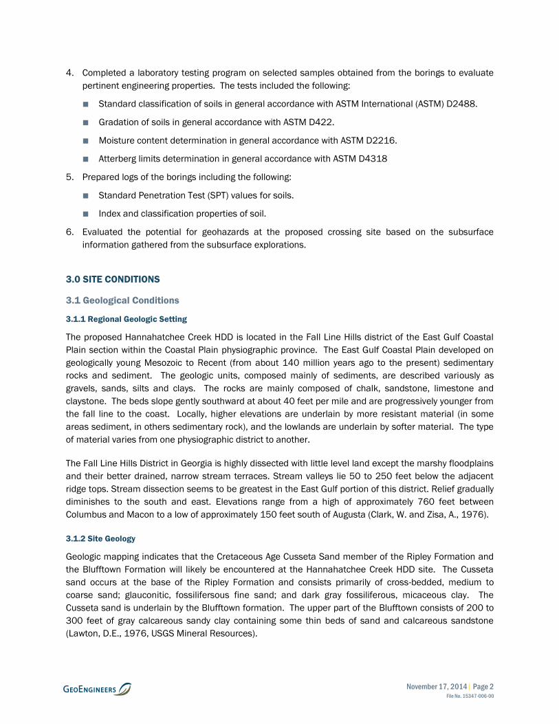
Figure 1. Vicinity Map
Figure 2. Site Plan and Profile
Figure 3. Geologic Map
Figures 4 and 5. Site Photographs
APPENDICES
Appendix A. Field Explorations and Lab Testing
Figure A-1 – Key to Exploration Logs
Figures A-2 through A-4 – Logs of Borings
Figures A-5 through A-9 - Sieve Analysis Results
Figures A-10 and A-11 – Atterberg Limits Test Results
Appendix B. Report Limitations and Guidelines for Use
November 17, 2014| Page 1 File No. 15347-006-00
1.0 INTRODUCTION
GeoEngineers, Inc. (GeoEngineers) is pleased to submit this geotechnical data report for the proposed
Sabal Trail Transmission Project (Sabal Trail) Hannahatchee Creek Horizontal Directional Drill (HDD) at
approximate milepost (MP) 91.5 located in Stewart County, Georgia. The location of the site is shown on
the Vicinity Map Figure 1.
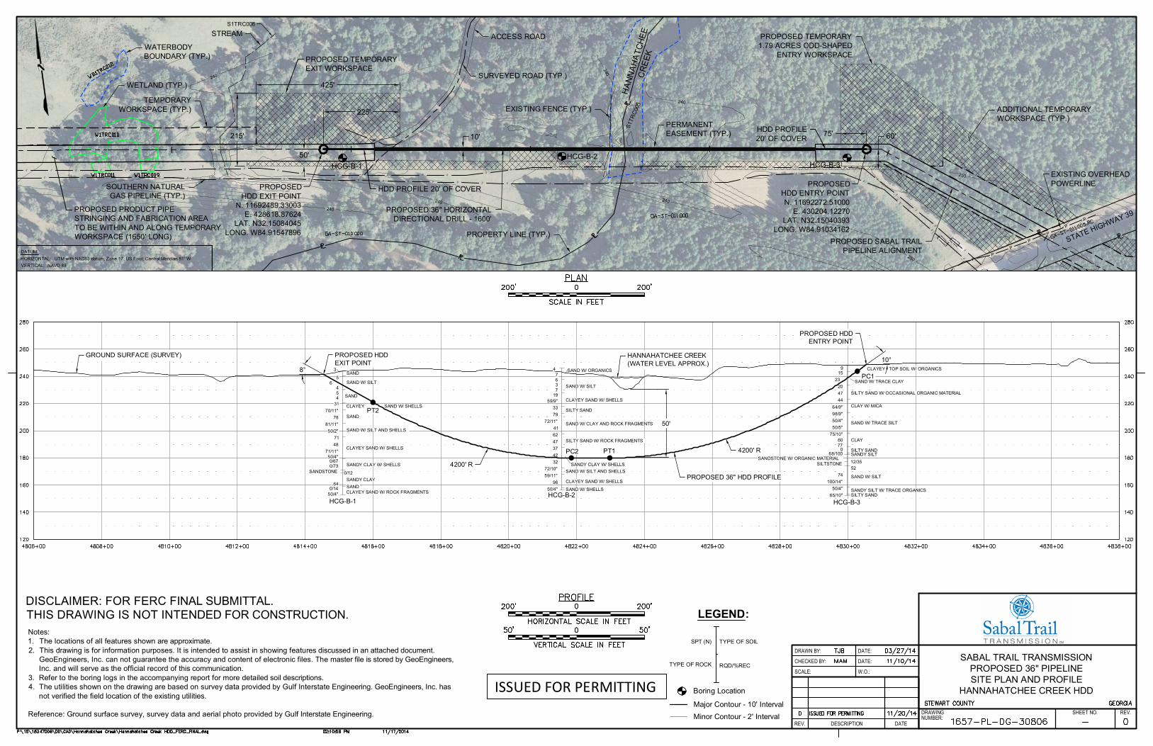
The proposed project consists of a new 36-inch diameter steel pipeline to be installed using the HDD
method of construction as part of a new approximately 475-mile long interstate natural gas pipeline
project. The design horizontal length of the proposed Hannahatchee Creek HDD is 1,600 feet, crossing
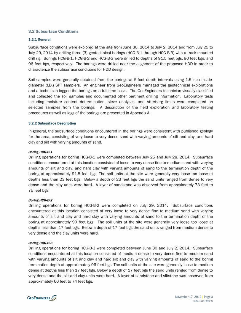
beneath Hannahatchee Creek and a connector road. The general layout of the site is shown in the Site
Plan, Figure 2.
We explored subsurface conditions near the proposed HDD site by drilling three geotechnical borings
(HCG-B-1 through HCG-B-3) to depths up to 96 feet below ground surface (bgs) adjacent to the alignment
of the proposed HDD. In general, the subsurface conditions encountered in the borings were consistent
with published geology for the area. Details of our subsurface exploration program are included in
Section 3.2 and the exploration logs are included in Appendix A.
2.0 SCOPE
The purpose of our services was to evaluate the existing surface and subsurface soil and groundwater
conditions and to prepare a geotechnical data report. The specific scope of services provided by
GeoEngineers included the following:
Task 1 – Conceptual HDD Plan and Profile Drawings
1. Reviewed available project information provided by Gulf Interstate Engineering (GIE) and publicly
available geologic maps, subsurface information, ground surface elevation data, aerial photographs
and other documentation for the project area.
2. Prepared a conceptual HDD alignment and profile drawing with proposed boring locations based on
topographic data from publicly available sources.
Task 2 – Site Reconnaissance
1. Performed an engineer site visit to the proposed crossing to observe site access, surface conditions,
and potential HDD constructability issues.
Task 3 – Geotechnical Exploration and Laboratory Testing
1. Contacted the applicable “One Call” agency to notify them of our intent to perform soil borings at the
site and to clear the boring locations of potential underground utilities.
2. Explored subsurface conditions at the site by completing a total of three (3) geotechnical borings to
depths between 90 and 96 feet below ground surface (bgs) using hollow-stem auger and/or mud
rotary drilling techniques. The explorations were completed using a track-mounted drill rig.
3. Backfilled the borings full-depth with cement-bentonite grout upon completion.
November 17, 2014| Page 2 File No. 15347-006-00
4. Completed a laboratory testing program on selected samples obtained from the borings to evaluate
pertinent engineering properties. The tests included the following:
■ Standard classification of soils in general accordance with ASTM International (ASTM) D2488.
■ Gradation of soils in general accordance with ASTM D422.
■ Moisture content determination in general accordance with ASTM D2216.
■ Atterberg limits determination in general accordance with ASTM D4318
5. Prepared logs of the borings including the following:
■ Standard Penetration Test (SPT) values for soils.
■ Index and classification properties of soil.
6. Evaluated the potential for geohazards at the proposed crossing site based on the subsurface
information gathered from the subsurface explorations.
3.0 SITE CONDITIONS
3.1 Geological Conditions
3.1.1 Regional Geologic Setting
The proposed Hannahatchee Creek HDD is located in the Fall Line Hills district of the East Gulf Coastal
Plain section within the Coastal Plain physiographic province. The East Gulf Coastal Plain developed on
geologically young Mesozoic to Recent (from about 140 million years ago to the present) sedimentary
rocks and sediment. The geologic units, composed mainly of sediments, are described variously as
gravels, sands, silts and clays. The rocks are mainly composed of chalk, sandstone, limestone and
claystone. The beds slope gently southward at about 40 feet per mile and are progressively younger from
the fall line to the coast. Locally, higher elevations are underlain by more resistant material (in some
areas sediment, in others sedimentary rock), and the lowlands are underlain by softer material. The type
of material varies from one physiographic district to another.
The Fall Line Hills District in Georgia is highly dissected with little level land except the marshy floodplains
and their better drained, narrow stream terraces. Stream valleys lie 50 to 250 feet below the adjacent
ridge tops. Stream dissection seems to be greatest in the East Gulf portion of this district. Relief gradually
diminishes to the south and east. Elevations range from a high of approximately 760 feet between
Columbus and Macon to a low of approximately 150 feet south of Augusta (Clark, W. and Zisa, A., 1976).
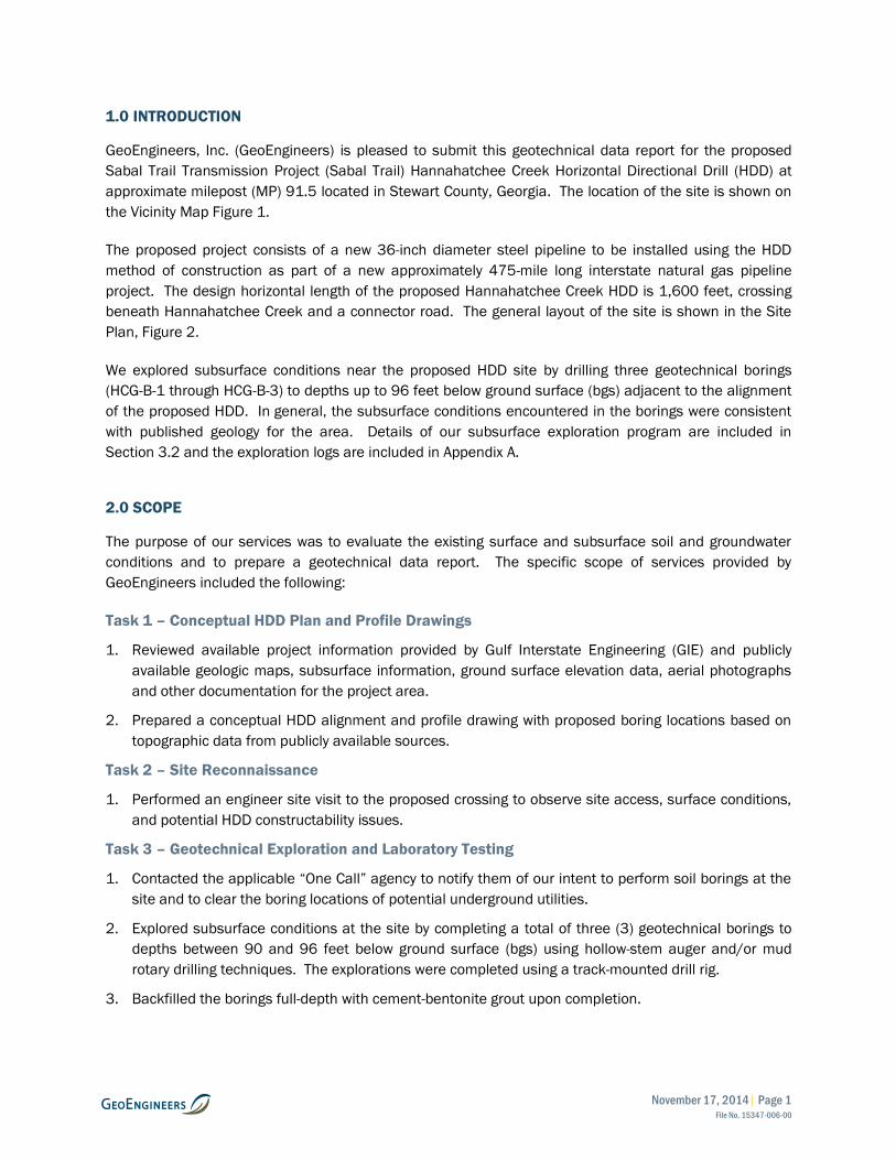
3.1.2 Site Geology
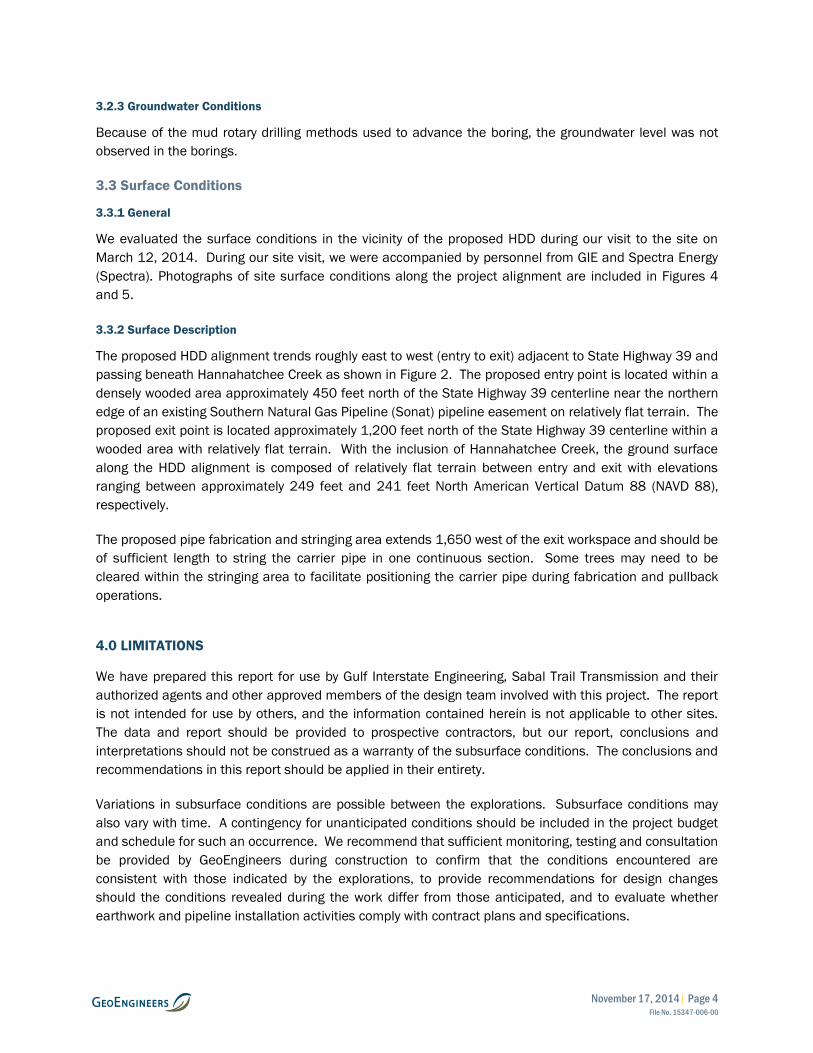
Geologic mapping indicates that the Cretaceous Age Cusseta Sand member of the Ripley Formation and
the Blufftown Formation will likely be encountered at the Hannahatchee Creek HDD site. The Cusseta
sand occurs at the base of the Ripley Formation and consists primarily of cross-bedded, medium to
coarse sand; glauconitic, fossilifersous fine sand; and dark gray fossiliferous, micaceous clay. The
Cusseta sand is underlain by the Blufftown formation. The upper part of the Blufftown consists of 200 to
300 feet of gray calcareous sandy clay containing some thin beds of sand and calcareous sandstone
(Lawton, D.E., 1976, USGS Mineral Resources).
November 17, 2014| Page 3 File No. 15347-006-00
3.2 Subsurface Conditions
3.2.1 General
Subsurface conditions were explored at the site from June 30, 2014 to July 2, 2014 and from July 25 to
July 29, 2014 by drilling three (3) geotechnical borings (HCG-B-1 through HCG-B-3) with a track-mounted
drill rig. Borings HCG-B-1, HCG-B-2 and HCG-B-3 were drilled to depths of 91.5 feet bgs, 90 feet bgs, and
96 feet bgs, respectively. The borings were drilled near the alignment of the proposed HDD in order to
characterize the subsurface conditions for HDD design.
Soil samples were generally obtained from the borings at 5-foot depth intervals using 1.5-inch inside-
diameter (I.D.) SPT samplers. An engineer from GeoEngineers managed the geotechnical explorations
and a technician logged the borings on a full-time basis. The GeoEngineers technician visually classified
and collected the soil samples and documented other pertinent drilling information. Laboratory tests
including moisture content determination, sieve analyses, and Atterberg limits were completed on
selected samples from the borings. A description of the field exploration and laboratory testing
procedures as well as logs of the borings are presented in Appendix A.
3.2.2 Subsurface Description
In general, the subsurface conditions encountered in the borings were consistent with published geology
for the area, consisting of very loose to very dense sand with varying amounts of silt and clay, and hard
clay and silt with varying amounts of sand.
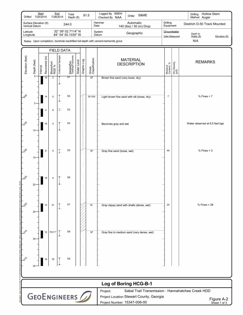
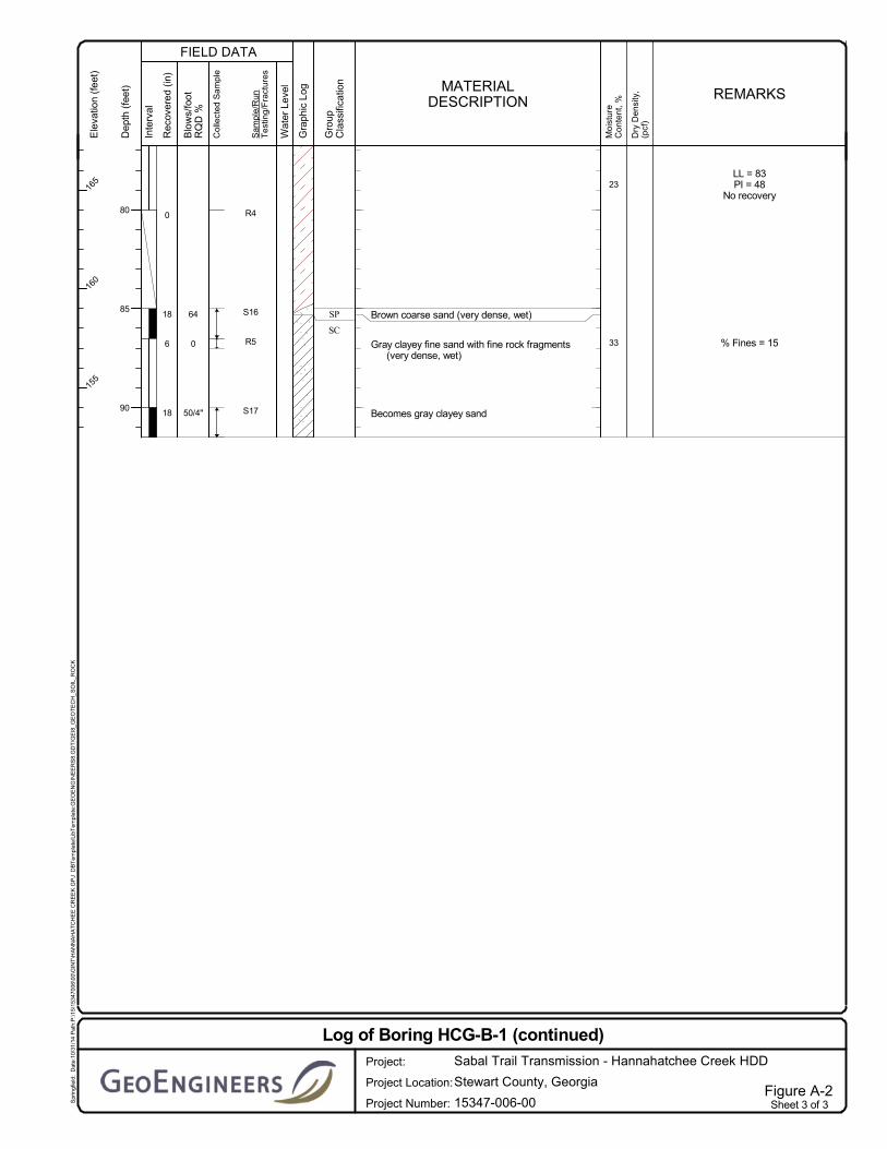
Boring HCG-B-1
Drilling operations for boring HCG-B-1 were completed between July 25 and July 28, 2014. Subsurface
conditions encountered at this location consisted of loose to very dense fine to medium sand with varying
amounts of silt and clay, and hard clay with varying amounts of sand to the termination depth of the
boring at approximately 91.5 feet bgs. The soil units at the site were generally very loose too loose at
depths less than 23 feet bgs. Below a depth of 23 feet bgs the sand units ranged from dense to very
dense and the clay units were hard. A layer of sandstone was observed from approximately 73 feet to
75 feet bgs.
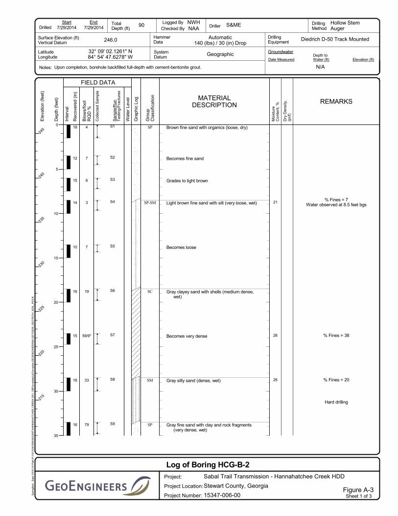
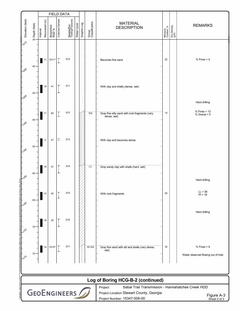
Boring HCG-B-2
Drilling operations for boring HCG-B-2 were completed on July 29, 2014. Subsurface conditions
encountered at this location consisted of very loose to very dense fine to medium sand with varying
amounts of silt and clay and hard clay with varying amounts of sand to the termination depth of the
boring at approximately 90 feet bgs. The soil units at the site were generally very loose too loose at
depths less than 17 feet bgs. Below a depth of 17 feet bgs the sand units ranged from medium dense to
very dense and the clay units were hard.
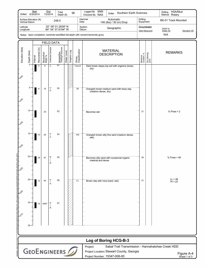
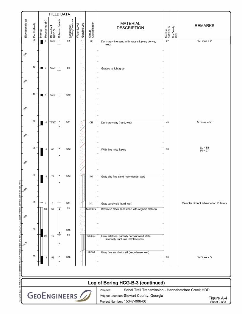
Boring HCG-B-3
Drilling operations for boring HCG-B-3 were completed between June 30 and July 2, 2014. Subsurface
conditions encountered at this location consisted of medium dense to very dense fine to medium sand
with varying amounts of silt and clay and hard silt and clay with varying amounts of sand to the boring
termination depth at approximately 96 feet bgs. The soil units at the site were generally loose to medium
dense at depths less than 17 feet bgs. Below a depth of 17 feet bgs the sand units ranged from dense to
very dense and the silt and clay units were hard. A layer of sandstone and siltstone was observed from
approximately 66 feet to 74 feet bgs.
November 17, 2014| Page 4 File No. 15347-006-00
3.2.3 Groundwater Conditions
Because of the mud rotary drilling methods used to advance the boring, the groundwater level was not
observed in the borings.
3.3 Surface Conditions
3.3.1 General
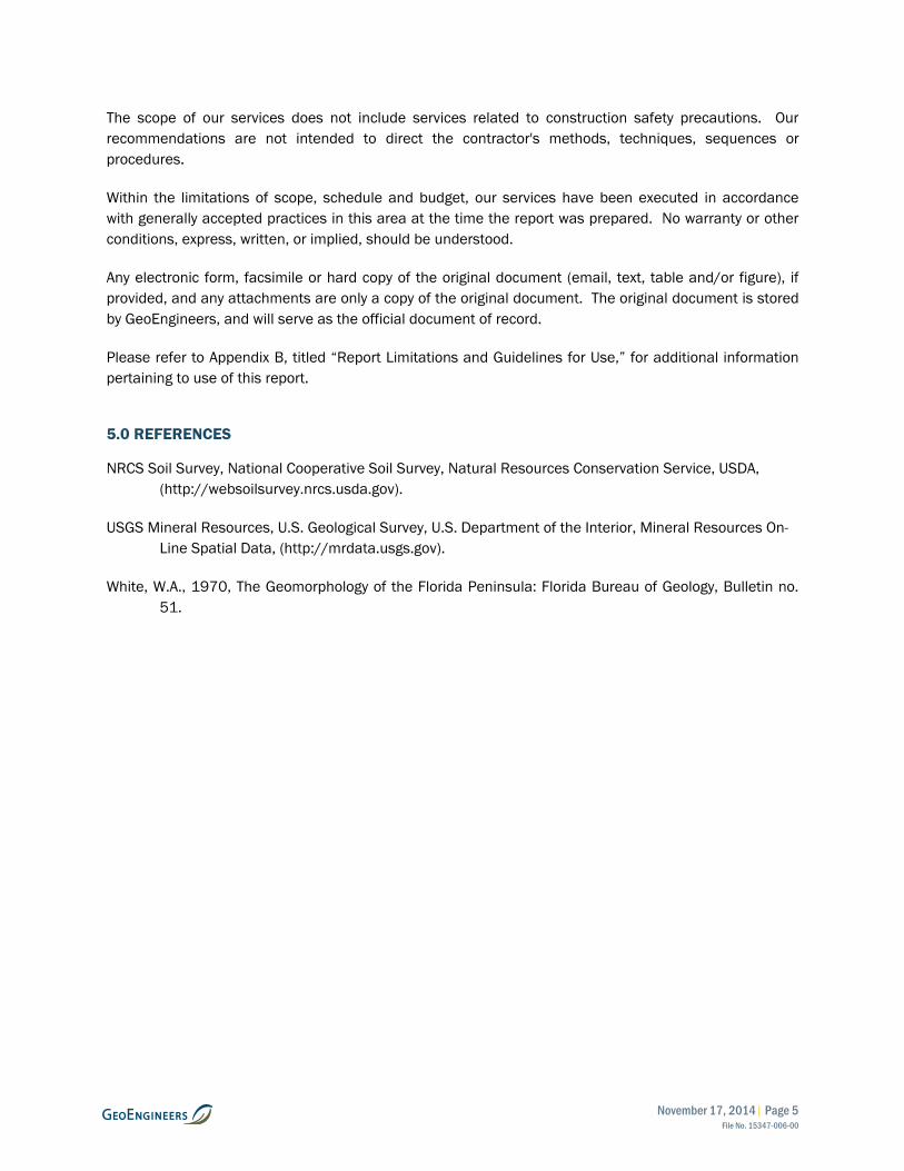
We evaluated the surface conditions in the vicinity of the proposed HDD during our visit to the site on
March 12, 2014. During our site visit, we were accompanied by personnel from GIE and Spectra Energy
(Spectra). Photographs of site surface conditions along the project alignment are included in Figures 4
and 5.
3.3.2 Surface Description
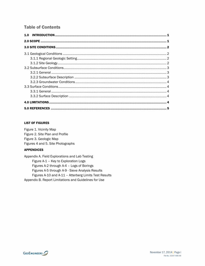
The proposed HDD alignment trends roughly east to west (entry to exit) adjacent to State Highway 39 and
passing beneath Hannahatchee Creek as shown in Figure 2. The proposed entry point is located within a
densely wooded area approximately 450 feet north of the State Highway 39 centerline near the northern
edge of an existing Southern Natural Gas Pipeline (Sonat) pipeline easement on relatively flat terrain. The
proposed exit point is located approximately 1,200 feet north of the State Highway 39 centerline within a
wooded area with relatively flat terrain. With the inclusion of Hannahatchee Creek, the ground surface
along the HDD alignment is composed of relatively flat terrain between entry and exit with elevations
ranging between approximately 249 feet and 241 feet North American Vertical Datum 88 (NAVD 88),
respectively.
The proposed pipe fabrication and stringing area extends 1,650 west of the exit workspace and should be
of sufficient length to string the carrier pipe in one continuous section. Some trees may need to be
cleared within the stringing area to facilitate positioning the carrier pipe during fabrication and pullback
operations.
4.0 LIMITATIONS
We have prepared this report for use by Gulf Interstate Engineering, Sabal Trail Transmission and their
authorized agents and other approved members of the design team involved with this project. The report
is not intended for use by others, and the information contained herein is not applicable to other sites.
The data and report should be provided to prospective contractors, but our report, conclusions and
interpretations should not be construed as a warranty of the subsurface conditions. The conclusions and
recommendations in this report should be applied in their entirety.
Variations in subsurface conditions are possible between the explorations. Subsurface conditions may
also vary with time. A contingency for unanticipated conditions should be included in the project budget
and schedule for such an occurrence. We recommend that sufficient monitoring, testing and consultation
be provided by GeoEngineers during construction to confirm that the conditions encountered are
consistent with those indicated by the explorations, to provide recommendations for design changes
should the conditions revealed during the work differ from those anticipated, and to evaluate whether
earthwork and pipeline installation activities comply with contract plans and specifications.
November 17, 2014| Page 5 File No. 15347-006-00
The scope of our services does not include services related to construction safety precautions. Our recommendations are not intended to direct the contractor's methods, techniques, sequences or procedures.
Within the limitations of scope, schedule and budget, our services have been executed in accordance with generally accepted practices in this area at the time the report was prepared. No warranty or other conditions, express, written, or implied, should be understood.
Any electronic form, facsimile or hard copy of the original document (email, text, table and/or figure), if provided, and any attachments are only a copy of the original document. The original document is stored by GeoEngineers, and will serve as the official document of record.
Please refer to Appendix B, titled “Report Limitations and Guidelines for Use,” for additional information pertaining to use of this report.
5.0 REFERENCES
NRCS Soil Survey, National Cooperative Soil Survey, Natural Resources Conservation Service, USDA, (http://websoilsurvey.nrcs.usda.gov).
USGS Mineral Resources, U.S. Geological Survey, U.S. Department of the Interior, Mineral Resources On-Line Spatial Data, (http://mrdata.usgs.gov).
White, W.A., 1970, The Geomorphology of the Florida Peninsula: Florida Bureau of Geology, Bulletin no. 51.

FIGU
RE
S

94
91
96
93
95
92
97
Stewart
SABAL TRAIL TRANSMISSION PROJECTVICINITY MAP
HANNAHATCHEE CREEK HDDSTEWART COUNTY, GEORGIA
Figure 1
µ1 0 1
Miles
Notes:1. The locations of all features shown are approximate.2. This drawing is for information purposes. It is intended toassist in showing features discussed in an attached document.GeoEngineers, Inc. cannot guarantee the accuracy and contentof electronic files. The master file is stored by GeoEngineers, Inc. and will serve as the official record of this communication.Data Sources: ESRI Data & Maps, Street Maps 2008.Imagery from ESRI Data Online.Projection: NAD 1983, UTM Zone 17 North.
Offic
e: SP
RPa
th: P
:\15\1
5347
006\G
IS\Vic
inity
Maps
\Han
naha
tchee
Cree
k HDD
- VM.
mxd
Map R
evise
d: 17
Nov
embe
r 201
4 m
cleve
nger
Russell
StewartBarbour
Marion
TerrellRandolph
Webster
Chattahoochee
Quitman
Lee
Schley
MaconMuscogee
Bullock
Taylor
Hannahatchee Creek HDD
Proposed Sabal Trail Pipeline Alignment
H i l l a b e e
H i l l a b e eC r e e kC r e e k
Louvale
50'
CLAYEY SAND W/ ROCK FRAGMENTSSANDSANDY CLAY
0/12
SANDY CLAY W/ SHELLS
CLAYEY SAND W/ SHELLS
SAND W/ SILT AND SHELLS
SAND
CLAYEY SAND W/ SHELLS
SAND
SAND W/ SILT
SAND3
56
454
3170/11"
7881/11"50/2"
7148
71/11"
0/6750/4"
0/73SANDSTONE
640/14
50/4"SAND W/ SHELLS
CLAYEY SAND W/ SHELLS
SAND W/ SILT AND SHELLSSANDY CLAY W/ SHELLS
SILTY SAND W/ ROCK FRAGMENTS
SAND W/ CLAY AND ROCK FRAGMENTS
SILTY SAND
CLAYEY SAND W/ SHELLS
SAND W/ SILT
SAND W/ ORGANICS
50/4"96
59/11"72/10"
324237476241
72/11"7933
59/9"197367
4
SANDY SILT W/ TRACE ORGANICSSILTY SAND65/10"
50/4"100/14"
74
SILTSTONESANDSTONE W/ ORGANIC MATERIAL
68/100
7760
75/10"50/5"50/4"98/9"64/9"
444720
2315
9 CLAYEY TOP SOIL W/ ORGANICS
SILTY SAND W/ OCCASIONAL ORGANIC MATERIAL
CLAY W/ MICA
SAND W/ TRACE CLAY
SAND W/ TRACE SILT
CLAY
SILTY SAND
12/3552
SAND W/ SILT
SANDY SILT
8°10°
0
240240
240
240
240
240
250
250
XX
XX
X
X X
X
PP
PP
P
PP
// // // // // // // // // // // // // // // // // // // // // // // // ////
// // //
//
//
//
//
// // // // // // // // ////
//// // // // //
////
// // // // // // // // // // // //
//
//
//
//
//
225'
50'
425'
215' 75' 60'
PROPOSEDHDD EXIT POINT
N. 11692489.33003E. 428618.87624
LAT. N32.15084045LONG. W84.91547896
PROPOSEDHDD ENTRY POINTN. 11692272.51000
E. 430204.12270LAT. N32.15040393
LONG. W84.91034162
10'
PROPOSED 36" HDD PROFILE
PROPOSED HDDENTRY POINT
PROPOSED HDDEXIT POINT
PROPOSED SABAL TRAILPIPELINE ALIGNMENT
PROPOSED 36" HORIZONTALDIRECTIONAL DRILL - 1600'
PROPOSED TEMPORARYEXIT WORKSPACE
PROPOSED TEMPORARY1.79 ACRES ODD-SHAPED
ENTRY WORKSPACE
PROPERTY LINE (TYP.)
GROUND SURFACE (SURVEY) HANNAHATCHEE CREEK(WATER LEVEL APPROX.)
STATE HIGHWAY 39
WETLAND (TYP.)
WATERBODYBOUNDARY (TYP.)
HDD PROFILE 20' OF COVER
HDD PROFILE20' OF COVER
SOUTHERN NATURALGAS PIPELINE (TYP.)
DATUM:HORIZONTAL:VERTICAL:
UTM with NAD83 datum, Zone 17, US Foot; Central Meridian 81° WNAVD 88
SABAL TRAIL TRANSMISSIONPROPOSED 36" PIPELINESITE PLAN AND PROFILE
HANNAHATCHEE CREEK HDD
STREAM
HAN
NAH
ATCH
EEC
REE
K
PROPOSED PRODUCT PIPESTRINGING AND FABRICATION AREATO BE WITHIN AND ALONG TEMPORARYWORKSPACE (1650' LONG)
PERMANENTEASEMENT (TYP.)
TEMPORARYWORKSPACE (TYP.)
S1TRC008
SHEET NO.
DRAWN BY:
CHECKED BY:
SCALE:
DATE:
DATE:
W.O.:
DRAWINGNUMBER:
REV.
REV. DESCRIPTION DATE
EXISTING OVERHEADPOWERLINE
EXISTING FENCE (TYP.) ADDITIONAL TEMPORARYWORKSPACE (TYP.)
HCG-B-1HCG-B-2
HCG-B-3
HCG-B-1HCG-B-2
HCG-B-3
PC2 PT1
PT2
PC1
4200' R
4200' R
ACCESS ROAD
Notes:1. The locations of all features shown are approximate.2. This drawing is for information purposes. It is intended to assist in showing features discussed in an attached document.
GeoEngineers, Inc. can not guarantee the accuracy and content of electronic files. The master file is stored by GeoEngineers,Inc. and will serve as the official record of this communication.
3. Refer to the boring logs in the accompanying report for more detailed soil descriptions.4. The utilities shown on the drawing are based on survey data provided by Gulf Interstate Engineering. GeoEngineers, Inc. has
not verified the field location of the existing utilities.
Reference: Ground surface survey, survey data and aerial photo provided by Gulf Interstate Engineering.
Boring Location
Major Contour - 10' IntervalMinor Contour - 2' Interval
TYPE OF SOIL
LEGEND:
RQD/%REC
SPT (N)
TYPE OF ROCK
DISCLAIMER: FOR FERC FINAL SUBMITTAL.THIS DRAWING IS NOT INTENDED FOR CONSTRUCTION.
ISSUED FOR PERMITTING
SURVEYED ROAD (TYP.)
S1TR
C00
5

0.5 0 0.5
Miles
Notes:1. The locations of all features shown are approximate.2. This drawing is for information purposes. It is intendedto assist in showing features discussed in an attached document. GeoEngineers, Inc. cannot guarantee the accuracy and contentof electronic files. The master file is stored by GeoEngineers, Inc.and will serve as the official record of this communication.Projection: NAD 1983 UTM Zone 16N
Sabal Trail Mileposts
Sabal Trail Alignment
Proposed HDD Location
Georgia Geology, Americus 30x60
Kb: Blufftown Formation
Kc: Cusseta Sand
Qal: Alluvium
Qth: Deposits of high alluvial terraces
Offic
e: PO
RTPa
th: P:
\15\
1534
7006
_GIS\
GIS\0
0\MX
D\15
3470
0600
_Han
naha
tchee
RiverH
DD.m
xdMa
p Rev
ised:
18 N
ovem
ber 2
014
cca
brera
MP 89
MP 94
MP 91
MP 88
MP 93
MP 90
MP 95
MP 92
MP 87
Data Source: Base geology maps from USGS National Geologic Map Database,http://ngmdb.usgs.gov/.
Geologic MapSabal Trail Transmission Project
Hannahatchee Creek HDDStewart County, Georgia
Figure 3
Hannahatchee Creek HDD

FIGURE 4
Looking Westward toward the Exit Workspace and Product Pipe Stringing Areafrom Boring HCG-B-1
Looking Eastward along the HDD Alignment and Sonat Pipeline’s Right-of-Waynear Boring HCG-B-1
Hannahatchee Creek HDD Site Photographs

FIGURE 5
Looking Eastward from the West Bank of the Hannahatchee Creek along the HDD Alignment
Looking Westward along the HDD Alignment from the Entry Workspace
Hannahatchee Creek HDD Site Photographs

AP
PE
ND
ICE
S

APPENDIX A Field Explorations and Laboratory Testing
November 17, 2014| Page A-1 File No. 15347-006-00
APPENDIX A
FIELD EXPLORATIONS AND LABORATORY TESTING
Field Explorations
Subsurface conditions were explored at the site between June 30, 2014 and July 2, 2014 and from
July 25 to July 29, 2014 by drilling three geotechnical borings (HCG-B-1 through HCG-B-3) using a track
mounted drilling rig. The borings were drilled to depths up to 96 feet bgs. The borings were drilled
adjacent to the alignment of the proposed HDD in order to characterize the subsurface conditions for
HDD design.
The drilling operations were managed by a GeoEngineers technician, who examined and classified the
soils encountered, obtained representative samples, observed groundwater conditions where possible
and prepared a detailed log of each exploration. The soil units encountered were classified visually in
general accordance with ASTM International (ASTM) D2488, which is described in Figure A-1. The
approximate locations of the explorations are shown in the Site Plan, Figure 2.
In general, soil samples were obtained from the borings at 5-foot-depth intervals using a 1.5-inch inside-
diameter (I.D.) split spoon standard penetration test (SPT) sampler. The SPT sampler was driven
18 inches using a 140-pound hammer with a 30-inch drop. The number of hammer blows required to
drive the sampler over three 6-inch intervals was recorded on field logs. The blows per foot representing
the sum of the last two 6-inch increments are shown in the boring logs. Each boring was backfilled with
Portland cement/bentonite grout.
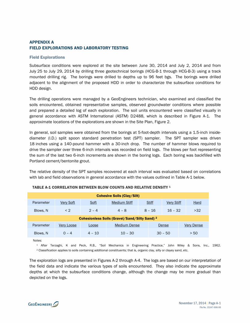
The relative density of the SPT samples recovered at each interval was evaluated based on correlations
with lab and field observations in general accordance with the values outlined in Table A-1 below.
TABLE A-1 CORRELATION BETWEEN BLOW COUNTS AND RELATIVE DENSITY 1
Cohesive Soils (Clay/Silt)
Parameter Very Soft Soft Medium Stiff Stiff Very Stiff Hard
Blows, N < 2 2 – 4 4 – 8 8 – 16 16 – 32 >32
Cohesionless Soils (Gravel/Sand/Silty Sand) 2
Parameter Very Loose Loose Medium Dense Dense Very Dense
Blows, N 0 – 4 4 – 10 10 – 30 30 – 50 > 50
Notes:
1 After Terzaghi, K and Peck, R.B., “Soil Mechanics in Engineering Practice,” John Wiley & Sons, Inc., 1962.
2 Classification applies to soils containing additional constituents; that is, organic clay, silty or clayey sand, etc.
The exploration logs are presented in Figures A-2 through A-4. The logs are based on our interpretation of
the field data and indicate the various types of soils encountered. They also indicate the approximate
depths at which the subsurface conditions change, although the change may be more gradual than
depicted on the logs.

November 17, 2014| Page A-2 File No. 15347-006-00
Laboratory Testing
General
Soil samples obtained from the explorations were transported to our Baton Rouge, Louisiana office and
examined to confirm or modify field classifications. Representative samples were selected for laboratory
testing consisting of moisture content determinations, sieve analyses and Atterberg limits determinations.
The laboratory testing procedures are discussed in more detail below.
Moisture Content Testing
Moisture content tests were completed for representative samples obtained from the explorations in
general accordance with ASTM D2216. The results of these tests are presented on the exploration logs
in Figures A-2 through A-4 at the depths at which the samples were obtained.
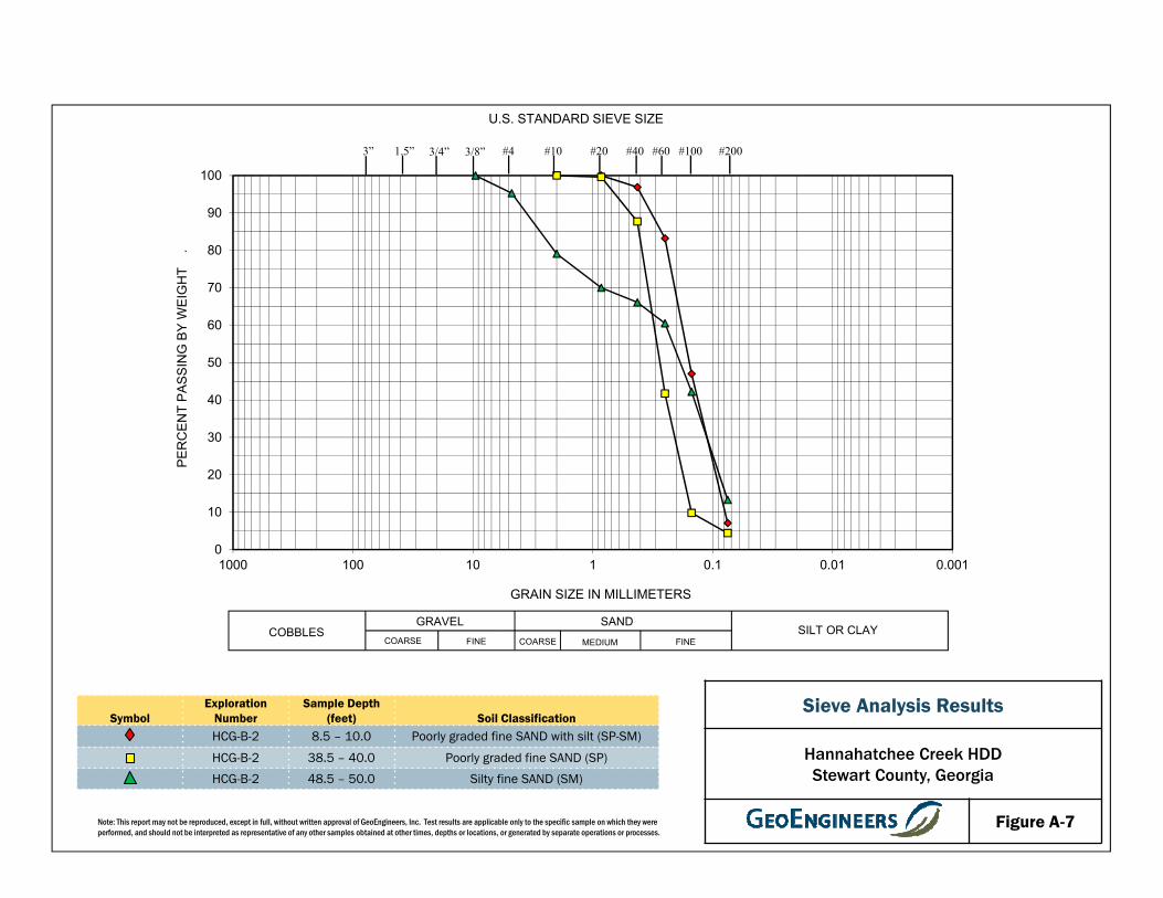
Sieve Analyses
Sieve analyses were performed on selected coarse-grained samples in general accordance with ASTM
D422. The results of the sieve analyses were plotted and classified in general accordance with the
Unified Soil Classification System (USCS) and are presented in Figures A-5 through A-9. The percentage
passing the U.S. No. 200 sieve is shown on the boring logs at the respective sample depths.
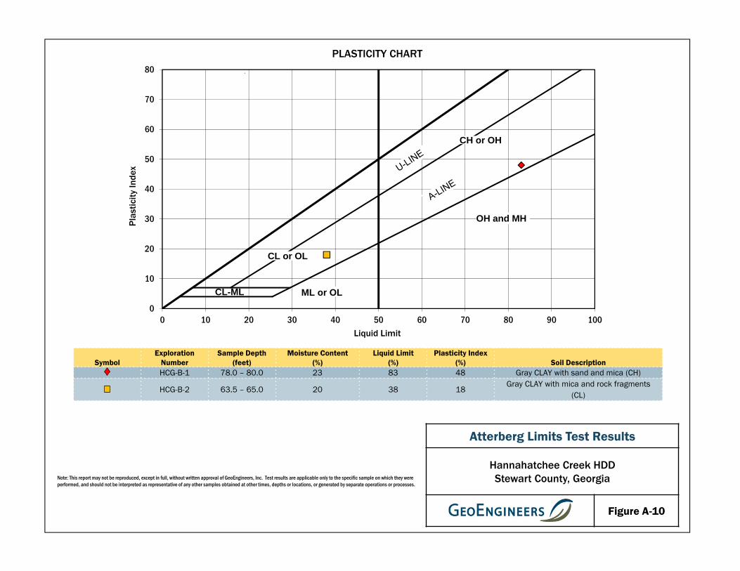
Atterberg Limits Testing
Atterberg Limits were performed on selected fine-grained soil samples in general accordance with ASTM
D4318. The tests were used to classify the soil as well as to evaluate its index properties. The results of
the Atterberg Limits testing are shown in Figures A-10 and A-11.

Blowcount is recorded for driven samplers as the numberof blows required to advance sampler 12 inches (ordistance noted). See exploration log for hammer weightand drop.
A "P" indicated sampler pused using the weight of the drill rig.
"WOH" indicates sampler pushed using the weight of the 140-pound SPT hammer.
NOTE: The reader must refer to the discussion in the report text and the logs of explorations for a proper understanding of subsurface conditions.Descriptions on the logs apply only at the specific exploration locations and at the time the explorations were made; they are not warranted to berepresentative of subsurface conditions at other locations or times.
Perched water observed at time ofexploration
SYMBOLS TYPICAL
KEY TO EXPLORATION LOGS
CC
CR
Groundwater observed at time ofexploration
Approximate location of soil stratachange within a geologic soil unit
Laboratory / Field Tests%FALCACPCSDSHAMCMDOCPMPPSATXUCVS
Standard Penetration Test (SPT)
Bulk or grab
Asphalt Concrete
Measured groundwater level inexploration, well, or piezometer
DESCRIPTIONSLETTER
Distinct contact between soil strata orgeologic units
Material Description Contact
Approximate location of soil stratachange within a geologic soil unit
Distinct contact between soil strata orgeologic units
TS
ADDITIONAL MATERIAL SYMBOLS
AC
Cement Concrete
Sampler Symbol Descriptions
GRAPH
Topsoil/Forest Duff/Sod
Percent finesAtterberg limitsChemical analysisLaboratory compaction testConsolidation testDirect shearHydrometer analysisMoisture contentMoisture content and dry densityOrganic contentPermeability or hydraulic conductivityPocket penetrometerSieve analysisTriaxial compressionUnconfined compressionVane shear
Piston
Crushed Rock/Quarry Spalls
Graphic Log Contact
GC
PT
OH
CH
MH
OL
ORGANIC CLAYS AND SILTS OFMEDIUM TO HIGH PLASTICITY
GM
GP
GW
DESCRIPTIONSTYPICAL
LETTERGRAPH
(APPRECIABLE AMOUNTOF FINES)
MORE THAN 50%RETAINED ON NO.
200 SIEVE
SYMBOLSMAJOR DIVISIONS
WELL-GRADED SANDS, GRAVELLYSANDS
SP
PEAT, HUMUS, SWAMP SOILS WITHHIGH ORGANIC CONTENTS
INORGANIC CLAYS OF HIGHPLASTICITY
(LITTLE OR NO FINES)
ORGANIC SILTS AND ORGANICSILTY CLAYS OF LOW PLASTICITY
INORGANIC CLAYS OF LOW TOMEDIUM PLASTICITY, GRAVELLYCLAYS, SANDY CLAYS, SILTY CLAYS,LEAN CLAYS
CLAYEY SANDS, SAND - CLAYMIXTURES
SILTY SANDS, SAND - SILTMIXTURES
CLAYEY GRAVELS, GRAVEL - SAND -CLAY MIXTURES
POORLY-GRADED GRAVELS,GRAVEL - SAND MIXTURES
ML
SC
SM
NOTE: Multiple symbols are used to indicate borderline or dual soil classifications
MORE THAN 50%PASSING NO. 200
SIEVE
MORE THAN 50%OF COARSEFRACTION
PASSING NO. 4SIEVE
CLEAN SANDS
GRAVELS WITHFINES
CLEANGRAVELS
HIGHLY ORGANIC SOILS
SILTSAND
CLAYS
SILTSAND
CLAYS
SANDAND
SANDYSOILS
GRAVELAND
GRAVELLYSOILS
(LITTLE OR NO FINES)
FINEGRAINED
SOILS
COARSEGRAINED
SOILS
SW
MORE THAN 50%OF COARSEFRACTION
RETAINED ON NO.4 SIEVE
CL
WELL-GRADED GRAVELS, GRAVEL -SAND MIXTURES
POORLY-GRADED SANDS,GRAVELLY SAND
INORGANIC SILTS, ROCK FLOUR,CLAYEY SILTS WITH SLIGHTPLASTICITY
INORGANIC SILTS, MICACEOUS ORDIATOMACEOUS SILTY SOILS
SILTY GRAVELS, GRAVEL - SAND -SILT MIXTURES
(APPRECIABLE AMOUNTOF FINES)
SOIL CLASSIFICATION CHART
LIQUID LIMITGREATER THAN 50
LIQUID LIMITLESS THAN 50
SANDS WITHFINES
Shelby tube
Direct-Push
FIGURE A-1
SP
SP-SM
SP
SC
SP
18
14
4
18
8
18
12
12
16
3
5
6
4
5
4
31
70/11"
78
S1
S2
S3
S4
S5
S6
S7
S8
S9
Brown fine sand (very loose, dry)
Light brown fine sand with silt (loose, dry)
Becomes gray and wet
Gray fine sand (loose, wet)
Gray clayey sand with shells (dense, wet)
Gray fine to medium sand (very dense, wet)
7
44
24
% Fines = 7
Water observed at 8.5 feet bgs
% Fines = 3
% Fines = 28
TotalDepth (ft)
HammerData
SystemDatum
StartChecked ByLogged By
NAADrillingMethodDrilled
Notes:
NWH
Surface Elevation (ft)Vertical Datum
Hollow StemAugerDriller
GroundwaterDepth toWater (ft)Date Measured
Diedrich D-50 Track Mounted
Elevation (ft)
DrillingEquipment
LatitudeLongitude
32° 09' 02.7114" N84° 54' 55.1035" W Geographic
91.5
Upon completion, borehole backfilled full-depth with cement-bentonite grout.
Automatic140 (lbs) / 30 (in) Drop
244.0
N/A
S&ME7/25/2014End
7/28/2014
Sheet 1 of 3Figure A-2
Log of Boring HCG-B-1
Project Location:
Project:
Project Number:
Sabal Trail Transmission - Hannahatchee Creek HDD
15347-006-00
Stewart County, Georgia
Spr
ingf
ield
: D
ate:
10/3
1/14
Pat
h:P
:\15\
1534
7006
\00\
GIN
T\H
AN
NA
HA
TC
HE
E C
RE
EK
.GP
J D
BT
empl
ate/
LibT
empl
ate:
GE
OE
NG
INE
ER
S8.
GD
T/G
EI8
_GE
OT
EC
H_S
OIL
_RO
CK
FIELD DATA
Ele
vatio
n (f
eet)
240
235
230
225
220
215
210
Dep
th (
feet
)
0
5
10
15
20
25
30
35
Col
lect
ed S
ampl
e
Gro
upC
lass
ifica
tion
Inte
rval
Rec
over
ed (
in)
Blo
ws/
foot
RQ
D %
Sam
ple/
Run
Tes
ting
/Fra
ctur
es
MATERIALDESCRIPTION
Gra
phic
Log
Wat
er L
evel
Moi
stur
eC
onte
nt,
%
Dry
Den
sity
,(p
cf)
REMARKS

SP-SM
SC
CL
Sandstone
CH
17
8
18
18
12
4
40
44
7
81/11"
50/2"
71
48
71/11"
50/4"
S10
S11
S12
S13
S14
S15
R1
R2
R3
0
0
0
Gray fine sand with silt and shells (very dense,wet)
Gray clayey fine sand with shells (very dense,wet)
Becomes clayey fine sand (dense, wet)
With shells and becomes very dense
With rock fragments
Gray sandy clay with shells (hard, wet)
Gray sandstone, visually fresh state, pit quality,3D discontinuities
Gray hard sandy clay
24
20
30
% Fines = 7
% Fines = 12% Gravel = 3
% Fines = 18
Auger refusal at 65' bgs, potential cobble
Clear water observed flowing from the hole
Sheet 2 of 3Figure A-2
Log of Boring HCG-B-1 (continued)
Project Location:
Project:
Project Number:
Sabal Trail Transmission - Hannahatchee Creek HDD
15347-006-00
Stewart County, Georgia
Spr
ingf
ield
: D
ate:
10/3
1/14
Pat
h:P
:\15\
1534
7006
\00\
GIN
T\H
AN
NA
HA
TC
HE
E C
RE
EK
.GP
J D
BT
empl
ate/
LibT
empl
ate:
GE
OE
NG
INE
ER
S8.
GD
T/G
EI8
_GE
OT
EC
H_S
OIL
_RO
CK
FIELD DATA
Ele
vatio
n (f
eet)
205
200
195
190
185
180
175
170
Dep
th (
feet
)
35
40
45
50
55
60
65
70
75
Col
lect
ed S
ampl
e
Gro
upC
lass
ifica
tion
Inte
rval
Rec
over
ed (
in)
Blo
ws/
foot
RQ
D %
Sam
ple/
Run
Tes
ting
/Fra
ctur
es
MATERIALDESCRIPTION
Gra
phic
Log
Wat
er L
evel
Moi
stur
eC
onte
nt,
%
Dry
Den
sity
,(p
cf)
REMARKS
SP
SC
0
18
6
18
64
50/4"
R4
S16
R5
S17
0
Brown coarse sand (very dense, wet)
Gray clayey fine sand with fine rock fragments(very dense, wet)
Becomes gray clayey sand
23
33
LL = 83PI = 48
No recovery
% Fines = 15
Sheet 3 of 3Figure A-2
Log of Boring HCG-B-1 (continued)
Project Location:
Project:
Project Number:
Sabal Trail Transmission - Hannahatchee Creek HDD
15347-006-00
Stewart County, Georgia
Spr
ingf
ield
: D
ate:
10/3
1/14
Pat
h:P
:\15\
1534
7006
\00\
GIN
T\H
AN
NA
HA
TC
HE
E C
RE
EK
.GP
J D
BT
empl
ate/
LibT
empl
ate:
GE
OE
NG
INE
ER
S8.
GD
T/G
EI8
_GE
OT
EC
H_S
OIL
_RO
CK
FIELD DATA
Ele
vatio
n (f
eet)
165
160
155
Dep
th (
feet
)
80
85
90
Col
lect
ed S
ampl
e
Gro
upC
lass
ifica
tion
Inte
rval
Rec
over
ed (
in)
Blo
ws/
foot
RQ
D %
Sam
ple/
Run
Tes
ting
/Fra
ctur
es
MATERIALDESCRIPTION
Gra
phic
Log
Wat
er L
evel
Moi
stur
eC
onte
nt,
%
Dry
Den
sity
,(p
cf)
REMARKS
SP
SP-SM
SC
SM
SP
18
12
15
14
10
16
15
18
16
4
7
6
3
7
19
59/9"
33
79
S1
S2
S3
S4
S5
S6
S7
S8
S9
Brown fine sand with organics (loose, dry)
Becomes fine sand
Grades to light brown
Light brown fine sand with silt (very loose, wet)
Becomes loose
Gray clayey sand with shells (medium dense,wet)
Becomes very dense
Gray silty sand (dense, wet)
Gray fine sand with clay and rock fragments(very dense, wet)
21
26
26
% Fines = 7Water observed at 8.5 feet bgs
% Fines = 38
% Fines = 20
Hard drilling
TotalDepth (ft)
HammerData
SystemDatum
StartChecked ByLogged By
NAADrillingMethodDrilled
Notes:
NWH
Surface Elevation (ft)Vertical Datum
Hollow StemAugerDriller
GroundwaterDepth toWater (ft)Date Measured
Diedrich D-50 Track Mounted
Elevation (ft)
DrillingEquipment
LatitudeLongitude
32° 09' 02.1261" N84° 54' 47.6278" W Geographic
90
Upon completion, borehole backfilled full-depth with cement-bentonite grout.
Automatic140 (lbs) / 30 (in) Drop
246.0
N/A
S&ME7/29/2014End
7/29/2014
Sheet 1 of 3Figure A-3
Log of Boring HCG-B-2
Project Location:
Project:
Project Number:
Sabal Trail Transmission - Hannahatchee Creek HDD
15347-006-00
Stewart County, Georgia
Spr
ingf
ield
: D
ate:
10/3
1/14
Pat
h:P
:\15\
1534
7006
\00\
GIN
T\H
AN
NA
HA
TC
HE
E C
RE
EK
.GP
J D
BT
empl
ate/
LibT
empl
ate:
GE
OE
NG
INE
ER
S8.
GD
T/G
EI8
_GE
OT
EC
H_S
OIL
_RO
CK
FIELD DATA
Ele
vatio
n (f
eet)
245
240
235
230
225
220
215
Dep
th (
feet
)
0
5
10
15
20
25
30
35
Col
lect
ed S
ampl
e
Gro
upC
lass
ifica
tion
Inte
rval
Rec
over
ed (
in)
Blo
ws/
foot
RQ
D %
Sam
ple/
Run
Tes
ting
/Fra
ctur
es
MATERIALDESCRIPTION
Gra
phic
Log
Wat
er L
evel
Moi
stur
eC
onte
nt,
%
Dry
Den
sity
,(p
cf)
REMARKS
SM
CL
SP-SM
11
18
11
4
18
14
18
14
72/11"
41
62
47
37
42
32
72/10"
S10
S11
S12
S13
S14
S15
S16
S17
Becomes fine sand
With clay and shells (dense, wet)
Gray fine silty sand with rock fragments (verydense, wet)
With clay and becomes dense
Gray sandy clay with shells (hard, wet)
With rock fragments
Gray fine sand with silt and shells (very dense,wet)
22
14
20
30
% Fines = 4
Hard drilling
% Fines = 13% Gravel = 5
Hard drilling
LL = 38PI = 18
Hard drilling
% Fines = 9
Water observed flowing out of hole
Sheet 2 of 3Figure A-3
Log of Boring HCG-B-2 (continued)
Project Location:
Project:
Project Number:
Sabal Trail Transmission - Hannahatchee Creek HDD
15347-006-00
Stewart County, Georgia
Spr
ingf
ield
: D
ate:
10/3
1/14
Pat
h:P
:\15\
1534
7006
\00\
GIN
T\H
AN
NA
HA
TC
HE
E C
RE
EK
.GP
J D
BT
empl
ate/
LibT
empl
ate:
GE
OE
NG
INE
ER
S8.
GD
T/G
EI8
_GE
OT
EC
H_S
OIL
_RO
CK
FIELD DATA
Ele
vatio
n (f
eet)
210
205
200
195
190
185
180
175
170
Dep
th (
feet
)
35
40
45
50
55
60
65
70
75
Col
lect
ed S
ampl
e
Gro
upC
lass
ifica
tion
Inte
rval
Rec
over
ed (
in)
Blo
ws/
foot
RQ
D %
Sam
ple/
Run
Tes
ting
/Fra
ctur
es
MATERIALDESCRIPTION
Gra
phic
Log
Wat
er L
evel
Moi
stur
eC
onte
nt,
%
Dry
Den
sity
,(p
cf)
REMARKS

SC
SP
11
13
4
59/11"
96
50/4"
S18
S19
S20
Gray fine clayey sand with shells (very dense,wet)
Gray fine sand with shells (very dense, wet)
33 % Fines = 17
Sheet 3 of 3Figure A-3
Log of Boring HCG-B-2 (continued)
Project Location:
Project:
Project Number:
Sabal Trail Transmission - Hannahatchee Creek HDD
15347-006-00
Stewart County, Georgia
Spr
ingf
ield
: D
ate:
10/3
1/14
Pat
h:P
:\15\
1534
7006
\00\
GIN
T\H
AN
NA
HA
TC
HE
E C
RE
EK
.GP
J D
BT
empl
ate/
LibT
empl
ate:
GE
OE
NG
INE
ER
S8.
GD
T/G
EI8
_GE
OT
EC
H_S
OIL
_RO
CK
FIELD DATA
Ele
vatio
n (f
eet)
165
160
Dep
th (
feet
)
80
85
90
Col
lect
ed S
ampl
e
Gro
upC
lass
ifica
tion
Inte
rval
Rec
over
ed (
in)
Blo
ws/
foot
RQ
D %
Sam
ple/
Run
Tes
ting
/Fra
ctur
es
MATERIALDESCRIPTION
Gra
phic
Log
Wat
er L
evel
Moi
stur
eC
onte
nt,
%
Dry
Den
sity
,(p
cf)
REMARKS
Topsoil
SP
SM
CL
5
9
10
18
12
15
9
15
23
20
47
44
64/9"
S1
S2
S3
S4
S5
S6
S7
Dark brown clayey top soil with organics (loose,dry)
Orangish brown medium sand with trace clay(medium dense, dry)
Becomes wet
Orangish brown silty fine sand (medium dense,wet)
Becomes silty sand with occasional organicmaterial and dense
Brown clay with mica (hard, wet)
21
29
31
% Fines = 2
% Fines = 49
LL = 48PI = 23
TotalDepth (ft)
HammerData
SystemDatum
StartChecked ByLogged By
NAADrillingMethodDrilled
Notes:
SNN
Surface Elevation (ft)Vertical Datum
HSA/MudRotaryDriller
GroundwaterDepth toWater (ft)Date Measured
BK-51 Track Mounted
Elevation (ft)
DrillingEquipment
LatitudeLongitude
32° 09' 01.2639" N84° 54' 37.9194" W Geographic
96
Upon completion, borehole backfilled full-depth with cement-bentonite grout.
Automatic140 (lbs) / 30 (in) Drop
248.0
N/A
Southern Earth Sciences6/30/2014End
7/2/2014
Sheet 1 of 3Figure A-4
Log of Boring HCG-B-3
Project Location:
Project:
Project Number:
Sabal Trail Transmission - Hannahatchee Creek HDD
15347-006-00
Stewart County, Georgia
Spr
ingf
ield
: D
ate:
10/3
1/14
Pat
h:P
:\15\
1534
7006
\00\
GIN
T\H
AN
NA
HA
TC
HE
E C
RE
EK
.GP
J D
BT
empl
ate/
LibT
empl
ate:
GE
OE
NG
INE
ER
S8.
GD
T/G
EI8
_GE
OT
EC
H_S
OIL
_RO
CK
FIELD DATA
Ele
vatio
n (f
eet)
245
240
235
230
225
220
215
Dep
th (
feet
)
0
5
10
15
20
25
30
35
Col
lect
ed S
ampl
e
Gro
upC
lass
ifica
tion
Inte
rval
Rec
over
ed (
in)
Blo
ws/
foot
RQ
D %
Sam
ple/
Run
Tes
ting
/Fra
ctur
es
MATERIALDESCRIPTION
Gra
phic
Log
Wat
er L
evel
Moi
stur
eC
onte
nt,
%
Dry
Den
sity
,(p
cf)
REMARKS
SP
CH
SM
ML
Sandstone
Siltstone
SP-SM
9
4
5
10
18
18
1
60
21
13
98/9"
50/4"
50/5"
75/10"
60
77
0
52
S8
S9
S10
S11
S12
S13
S14
R1
S15
R2
S16
68
12
Dark gray fine sand with trace silt (very dense,wet)
Grades to light gray
Dark gray clay (hard, wet)
WIth fine mica flakes
Gray silty fine sand (very dense, wet)
Gray sandy silt (hard, wet)
Brownish black sandstone with organic material
Gray siltstone, partially decomposed state,intensely fractures, 60º fractures
Gray fine sand with silt (very dense, wet)
27
45
39
26
% Fines = 2
% Fines = 58
LL = 53PI = 27
Sampler did not advance for 10 blows
% Fines = 5
Sheet 2 of 3Figure A-4
Log of Boring HCG-B-3 (continued)
Project Location:
Project:
Project Number:
Sabal Trail Transmission - Hannahatchee Creek HDD
15347-006-00
Stewart County, Georgia
Spr
ingf
ield
: D
ate:
10/3
1/14
Pat
h:P
:\15\
1534
7006
\00\
GIN
T\H
AN
NA
HA
TC
HE
E C
RE
EK
.GP
J D
BT
empl
ate/
LibT
empl
ate:
GE
OE
NG
INE
ER
S8.
GD
T/G
EI8
_GE
OT
EC
H_S
OIL
_RO
CK
FIELD DATA
Ele
vatio
n (f
eet)
210
205
200
195
190
185
180
175
Dep
th (
feet
)
35
40
45
50
55
60
65
70
75
Col
lect
ed S
ampl
e
Gro
upC
lass
ifica
tion
Inte
rval
Rec
over
ed (
in)
Blo
ws/
foot
RQ
D %
Sam
ple/
Run
Tes
ting
/Fra
ctur
es
MATERIALDESCRIPTION
Gra
phic
Log
Wat
er L
evel
Moi
stur
eC
onte
nt,
%
Dry
Den
sity
,(p
cf)
REMARKS
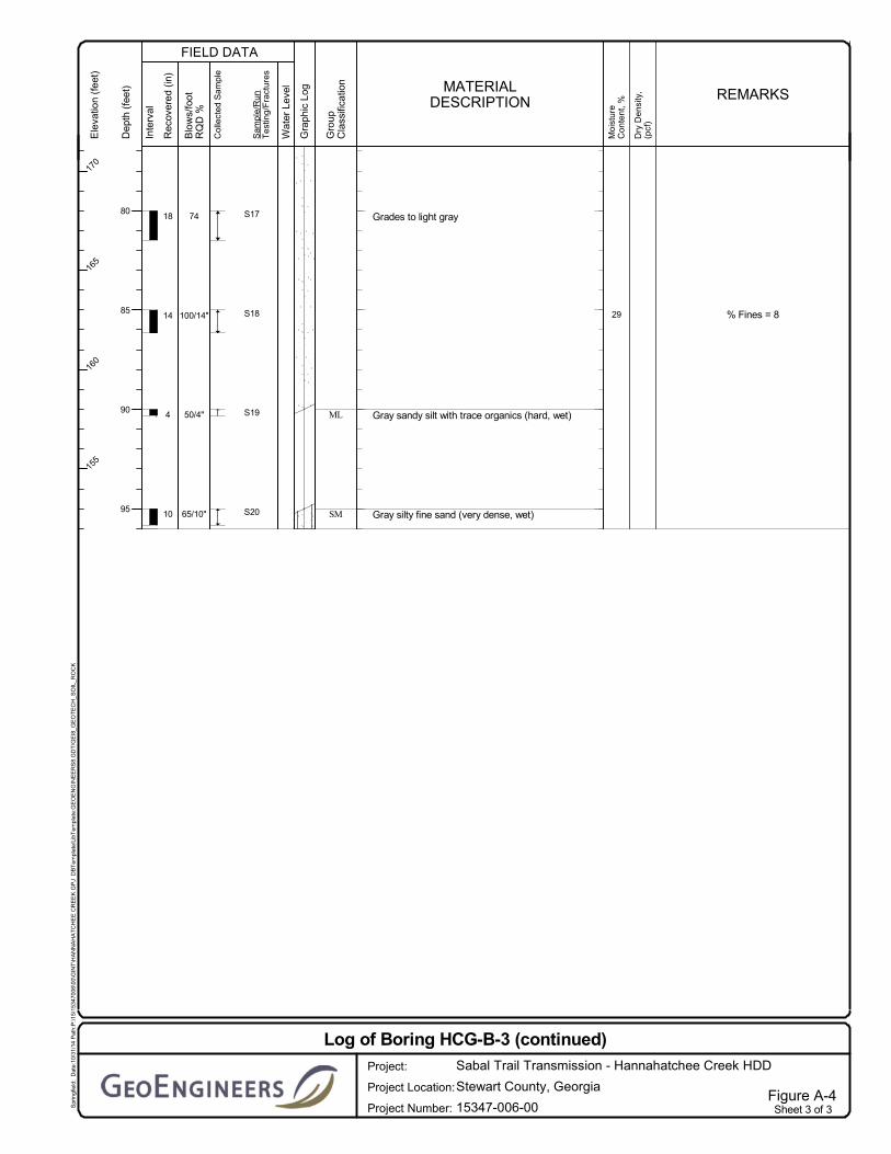
ML
SM
18
14
4
10
74
100/14"
50/4"
65/10"
S17
S18
S19
S20
Grades to light gray
Gray sandy silt with trace organics (hard, wet)
Gray silty fine sand (very dense, wet)
29 % Fines = 8
Sheet 3 of 3Figure A-4
Log of Boring HCG-B-3 (continued)
Project Location:
Project:
Project Number:
Sabal Trail Transmission - Hannahatchee Creek HDD
15347-006-00
Stewart County, Georgia
Spr
ingf
ield
: D
ate:
10/3
1/14
Pat
h:P
:\15\
1534
7006
\00\
GIN
T\H
AN
NA
HA
TC
HE
E C
RE
EK
.GP
J D
BT
empl
ate/
LibT
empl
ate:
GE
OE
NG
INE
ER
S8.
GD
T/G
EI8
_GE
OT
EC
H_S
OIL
_RO
CK
FIELD DATA
Ele
vatio
n (f
eet)
170
165
160
155
Dep
th (
feet
)
80
85
90
95
Col
lect
ed S
ampl
e
Gro
upC
lass
ifica
tion
Inte
rval
Rec
over
ed (
in)
Blo
ws/
foot
RQ
D %
Sam
ple/
Run
Tes
ting
/Fra
ctur
es
MATERIALDESCRIPTION
Gra
phic
Log
Wat
er L
evel
Moi
stur
eC
onte
nt,
%
Dry
Den
sity
,(p
cf)
REMARKS

Note: This report may not be reproduced, except in full, without written approval of GeoEngineers, Inc. Test results are applicable only to the specific sample on which they were performed, and should not be interpreted as representative of any other samples obtained at other times, depths or locations, or generated by separate operations or processes.
SANDSILT OR CLAYCOBBLES
GRAVELCOARSE MEDIUM FINECOARSE FINE
0
10
20
30
40
50
60
70
80
90
100
0.0010.010.11101001000
PER
CEN
T PA
SSIN
G B
Y W
EIG
HT
.
GRAIN SIZE IN MILLIMETERS
U.S. STANDARD SIEVE SIZE
3/8”3” 1.5” #4 #10 #20 #200#40 #60 #1003/4”
SymbolExploration
NumberSample Depth
(feet) Soil ClassificationHCG-B-1 3.5 – 5.0 Poorly graded fine SAND with silt (SP-SM)
HCG-B-1 13.5 – 15.0 Poorly graded fine to medium SAND (SP)
HCG-B-1 38.5 – 40.0 Poorly graded fine SAND with silt (SP-SM)
Sieve Analysis Results
Hannahatchee Creek HDDStewart County, Georgia
Figure A-5

Note: This report may not be reproduced, except in full, without written approval of GeoEngineers, Inc. Test results are applicable only to the specific sample on which they were performed, and should not be interpreted as representative of any other samples obtained at other times, depths or locations, or generated by separate operations or processes.
SANDSILT OR CLAYCOBBLES
GRAVELCOARSE MEDIUM FINECOARSE FINE
0
10
20
30
40
50
60
70
80
90
100
0.0010.010.11101001000
PER
CEN
T PA
SSIN
G B
Y W
EIG
HT
.
GRAIN SIZE IN MILLIMETERS
U.S. STANDARD SIEVE SIZE
3/8”3” 1.5” #4 #10 #20 #200#40 #60 #1003/4”
SymbolExploration
NumberSample Depth
(feet) Soil ClassificationHCG-B-1 43.5 – 45.0 Poorly graded fine SAND with silt (SP-SM)
HCG-B-1 58.5 – 60.0 Clayey fine SAND (SC)
HCG-B-1 85.0 – 86.5 Clayey fine SAND (SC)
Sieve Analysis Results
Hannahatchee Creek HDDStewart County, Georgia
Figure A-6
Note: This report may not be reproduced, except in full, without written approval of GeoEngineers, Inc. Test results are applicable only to the specific sample on which they were performed, and should not be interpreted as representative of any other samples obtained at other times, depths or locations, or generated by separate operations or processes.
SANDSILT OR CLAYCOBBLES
GRAVELCOARSE MEDIUM FINECOARSE FINE
0
10
20
30
40
50
60
70
80
90
100
0.0010.010.11101001000
PER
CEN
T PA
SSIN
G B
Y W
EIG
HT
.
GRAIN SIZE IN MILLIMETERS
U.S. STANDARD SIEVE SIZE
3/8”3” 1.5” #4 #10 #20 #200#40 #60 #1003/4”
SymbolExploration
NumberSample Depth
(feet) Soil ClassificationHCG-B-2 8.5 – 10.0 Poorly graded fine SAND with silt (SP-SM)
HCG-B-2 38.5 – 40.0 Poorly graded fine SAND (SP)
HCG-B-2 48.5 – 50.0 Silty fine SAND (SM)
Sieve Analysis Results
Hannahatchee Creek HDDStewart County, Georgia
Figure A-7

Note: This report may not be reproduced, except in full, without written approval of GeoEngineers, Inc. Test results are applicable only to the specific sample on which they were performed, and should not be interpreted as representative of any other samples obtained at other times, depths or locations, or generated by separate operations or processes.
SANDSILT OR CLAYCOBBLES
GRAVELCOARSE MEDIUM FINECOARSE FINE
0
10
20
30
40
50
60
70
80
90
100
0.0010.010.11101001000
PER
CEN
T PA
SSIN
G B
Y W
EIG
HT
.
GRAIN SIZE IN MILLIMETERS
U.S. STANDARD SIEVE SIZE
3/8”3” 1.5” #4 #10 #20 #200#40 #60 #1003/4”
SymbolExploration
NumberSample Depth
(feet) Soil ClassificationHCG-B-2 73.5 – 75.0 Poorly graded fine SAND with silt (SP-SM)
HCG-B-2 83.5 – 85.0 Clayey fine SAND (SC)
HCG-B-3 10.0 – 11.5 Poorly graded medium SAND (SP)
Sieve Analysis Results
Hannahatchee Creek HDDStewart County, Georgia
Figure A-8

Note: This report may not be reproduced, except in full, without written approval of GeoEngineers, Inc. Test results are applicable only to the specific sample on which they were performed, and should not be interpreted as representative of any other samples obtained at other times, depths or locations, or generated by separate operations or processes.
SANDSILT OR CLAYCOBBLES
GRAVELCOARSE MEDIUM FINECOARSE FINE
0
10
20
30
40
50
60
70
80
90
100
0.0010.010.11101001000
PER
CEN
T PA
SSIN
G B
Y W
EIG
HT
.
GRAIN SIZE IN MILLIMETERS
U.S. STANDARD SIEVE SIZE
3/8”3” 1.5” #4 #10 #20 #200#40 #60 #1003/4”
SymbolExploration
NumberSample Depth
(feet) Soil ClassificationHCG-B-3 35.0 – 36.5 Poorly graded fine SAND (SP)
HCG-B-3 75.0 – 76.5 Poorly graded fine SAND with silt (SP-SM)
HCG-B-3 85.0 – 86.5 Poorly graded fine SAND with silt (SP-SM)
Sieve Analysis Results
Hannahatchee Creek HDDStewart County, Georgia
Figure A-9
0
10
20
30
40
50
60
70
80
0 10 20 30 40 50 60 70 80 90 100
Pla
stic
ity In
dex
Liquid Limit
PLASTICITY CHART
Note: This report may not be reproduced, except in full, without written approval of GeoEngineers, Inc. Test results are applicable only to the specific sample on which they were performed, and should not be interpreted as representative of any other samples obtained at other times, depths or locations, or generated by separate operations or processes.
CL-ML ML or OL
CL or OL
OH and MH
CH or OH
SymbolExploration
NumberSample Depth
(feet)Moisture Content
(%)Liquid Limit
(%)Plasticity Index
(%) Soil DescriptionHCG-B-1 78.0 – 80.0 23 83 48 Gray CLAY with sand and mica (CH)
HCG-B-2 63.5 – 65.0 20 38 18Gray CLAY with mica and rock fragments
(CL)
Atterberg Limits Test Results
Hannahatchee Creek HDDStewart County, Georgia
Figure A-10

0
10
20
30
40
50
60
70
80
0 10 20 30 40 50 60 70 80 90 100
Pla
stic
ity In
dex
Liquid Limit
PLASTICITY CHART
Note: This report may not be reproduced, except in full, without written approval of GeoEngineers, Inc. Test results are applicable only to the specific sample on which they were performed, and should not be interpreted as representative of any other samples obtained at other times, depths or locations, or generated by separate operations or processes.
CL-ML ML or OL
CL or OL
OH and MH
CH or OH
SymbolExploration
NumberSample Depth
(feet)Moisture Content
(%)Liquid Limit
(%)Plasticity Index
(%) Soil DescriptionHCG-B-3 25.0 – 26.5 31 48 23 Gray CLAY with silt and mica (CL)HCG-B-3 55.0 – 56.5 39 53 27 Dark gray CLAY with Mica (CH)
Atterberg Limits Test Results
Hannahatchee Creek HDDStewart County, Georgia
Figure A-11

APPENDIX B Report Limitations and Guidelines for Use

November 17, 2014| Page B-1 File No. 15347-006-00
APPENDIX B
REPORT LIMITATIONS AND GUIDELINES FOR USE1
This appendix provides information to help you manage your risks with respect to the use of this report.
Geotechnical and Environmental Services Are Performed for Specific Purposes, Persons and
Projects
This report has been prepared for the exclusive use of Gulf Interstate Engineering, Sabal Trail
Transmission and their authorized agents. This report is not intended for use by others, and the
information contained herein is not applicable to other sites.
GeoEngineers structures our services to meet the specific needs of our clients. For example, a
geotechnical or geologic study conducted for a civil engineer or architect may not fulfill the needs of a
construction contractor or even another civil engineer or architect that are involved in the same project.
Similarly, an environmental assessment study conducted for a property owner may not fulfill the needs of
a prospective purchaser of the same property. Because each study is unique, each report is unique,
prepared solely for the specific client and project site. Our report is prepared for the exclusive use of our
Client. No other party may rely on the product of our services unless we agree in advance to such
reliance in writing. This is to provide our firm with reasonable protection against open-ended liability
claims by third parties with whom there would otherwise be no contractual limits to their actions. Within
the limitations of scope, schedule and budget, our services have been executed in accordance with our
Agreement with the Client and generally accepted geotechnical practices in this area at the time this
report was prepared. This report should not be applied for any purpose or project except the one
originally contemplated.
A Geotechnical Engineering or Environmental Report Is Based on a Unique Set of
Project-Specific Factors
This report has been prepared for the proposed Hannahatchee Creek HDD located in Stewart County,
Georgia. GeoEngineers considered a number of unique, project-specific factors when establishing the
scope of services for this project and report. Unless GeoEngineers specifically indicates otherwise, do not
rely on this report if it was:
■ not prepared for you,
■ not prepared for your project,
■ not prepared for the specific site explored, or
■ completed before important project changes were made.
For example, changes that can affect the applicability of this report include those that affect:
■ the function of the proposed structure;
1 Developed based on material provided by ASFE/The Best People on Earth, Professional Firms Practicing in the
Geosciences; www.asfe.org.
November 17, 2014| Page B-2 File NO. 15347-006-00
■ elevation, configuration, location, orientation or weight of the proposed structure;
■ composition of the design team; or
■ project ownership.
If important changes are made after the date of this report, GeoEngineers should be given the opportunity
to review our interpretations and recommendations and provide written modifications or confirmation, as
appropriate.
Subsurface Conditions Can Change
This report is based on conditions that existed at the time the study was performed. The findings and
conclusions of this report may be affected by the passage of time, by manmade events such as
construction on or adjacent to the site, by new releases of hazardous substances, or by natural events
such as floods, earthquakes, slope instability or groundwater fluctuations. Always contact GeoEngineers
before applying a report to determine if it remains applicable.
Most Geotechnical and Environmental Findings Are Professional Opinions
Our interpretations of subsurface conditions are based on field observations and laboratory test results
from widely spaced sampling locations at the site. Site exploration identifies subsurface conditions only
at those points where subsurface tests are conducted or samples are taken. GeoEngineers reviewed
field and laboratory data and then applied our professional judgment to render an opinion about
subsurface conditions throughout the site. Actual subsurface conditions may differ, sometimes
significantly, from those indicated in this report. Our report, conclusions and interpretations should not
be construed as a warranty of the subsurface conditions.
Do Not Redraw the Exploration Logs
Geotechnical engineers and geologists prepare final boring and testing logs based upon their
interpretation of field logs and laboratory data. To prevent errors or omissions, the logs included in a
geotechnical engineering or geologic report should never be redrawn for inclusion in architectural or other
design drawings. Only photographic or electronic reproduction is acceptable, but recognize that
separating logs from the report can elevate risk.
Contractors Are Responsible for Site Safety on Their Own Construction Projects
Our geotechnical recommendations are not intended to direct the contractor’s procedures, methods,
schedule or management of the work site. The contractor is solely responsible for job site safety and for
managing construction operations to minimize risks to on-site personnel and to adjacent properties.
Read These Provisions Closely
Some clients, design professionals and contractors may not recognize that the geoscience practices
(geotechnical engineering or geology) are far less exact than other engineering and natural science
disciplines. This lack of understanding can create unrealistic expectations that could lead to
disappointments, claims and disputes. GeoEngineers includes these explanatory “limitations” provisions
in our reports to help reduce such risks. Please confer with GeoEngineers if you are unclear how these
“Report Limitations and Guidelines for Use” apply to your project or site.

Have we delivered World Class Client Service?
Please let us know by visiting www.geoengineers.com/feedback.
Recommended