Nanyang Technological University
GPU-based Accelerated Spectral Caustic Rendering of Homogeneous Caustic Objects
Presenter: Budianto Tandianus
E-Mail : [email protected] : http:// sg.linkedin.com/in/eonstrifeWebsite : http://www.eonstrife.com
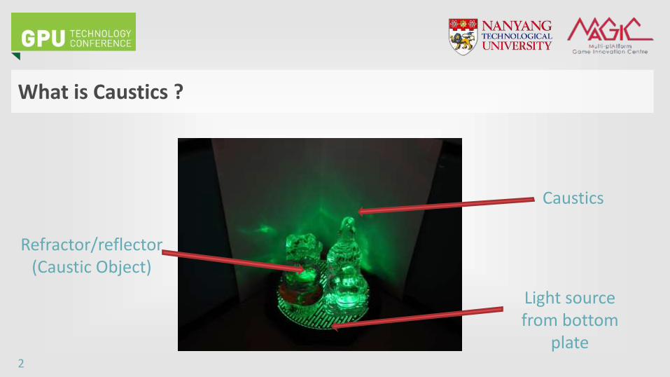
What is Caustics ?
2
Refractor/reflector(Caustic Object)
Caustics
Light sourcefrom bottom
plate
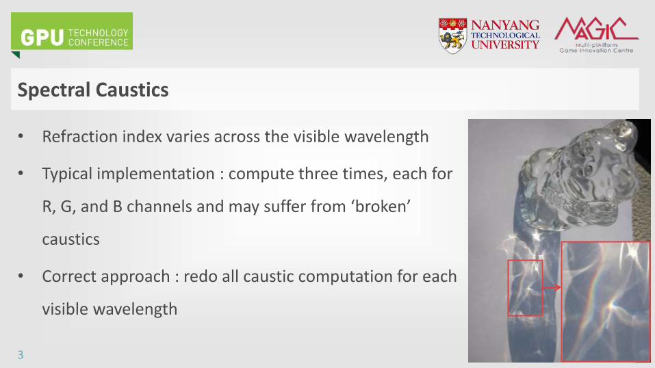
• Refraction index varies across the visible wavelength
• Typical implementation : compute three times, each for
R, G, and B channels and may suffer from ‘broken’
caustics
• Correct approach : redo all caustic computation for each
visible wavelength
Spectral Caustics
3
• Various rainbow-like effect, such as Light intereference on a thin layer (Sun et
al. 1999) and Diffraction (Imura et al. 2003)
• Spectral information compression, such as a set of linear basis functions
(Marimont and Wandell 1992)
• Photon mapping with spectral rendering, i.e. store the photons in RGB
representation (hence conversion spectral <-> RGB representations is
necessity) : Lai and Christensen 2007, Hachisuka 2007
Related Work
4
• Accelerate the full spectrum caustic computation while maintaining the quality
• Render using Stochastic Progressive Photon Mapping
• Two-step acceleration scheme :
– Cluster the wavelength based on refraction similarity : to reduce the
number of intersection tests
– Determine the number of iterations based on our defined importance level
Our Work (1/2)
5
• Combine both steps
– Refine each cluster (from 1st acceleration scheme) with the amount of
refinement computed from the 2nd acceleration scheme
• Is implemented using OptiX, a CUDA- based ray-tracer engine
• The work has been published at :
http://link.springer.com/article/10.1007/s00371-014-1037-z
Our Work (2/2)
6
Acceleration Scheme 1
• Basic idea : If the index of refraction for a range of wavelength is almost similar,
then the rays of those wavelength will be refracted to almost the same
direction. Hence, cluster the rays in this range of wavelength into a ray
• To reduce the number of intersection tests
• Cluster based on the change of the refraction angle with respect to the change
of wavelength
7
Acceleration Scheme 2 (1/2)
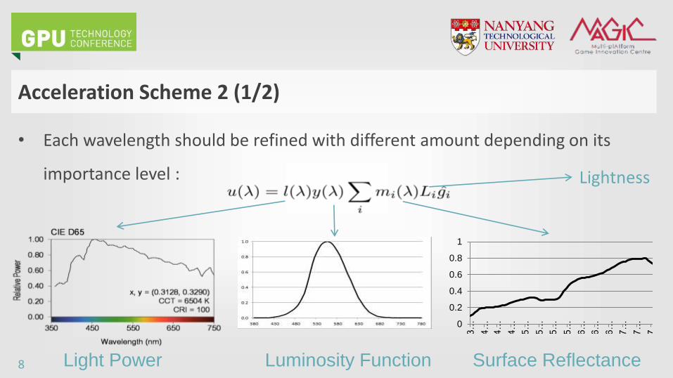
• Each wavelength should be refined with different amount depending on its
importance level :
0
0.2
0.4
0.6
0.8
1
3…
4…
4…
4…
5…
5…
5…
5…
6…
6…
6…
7…
7…
7…
Light Power Luminosity Function Surface Reflectance
Lightness
8
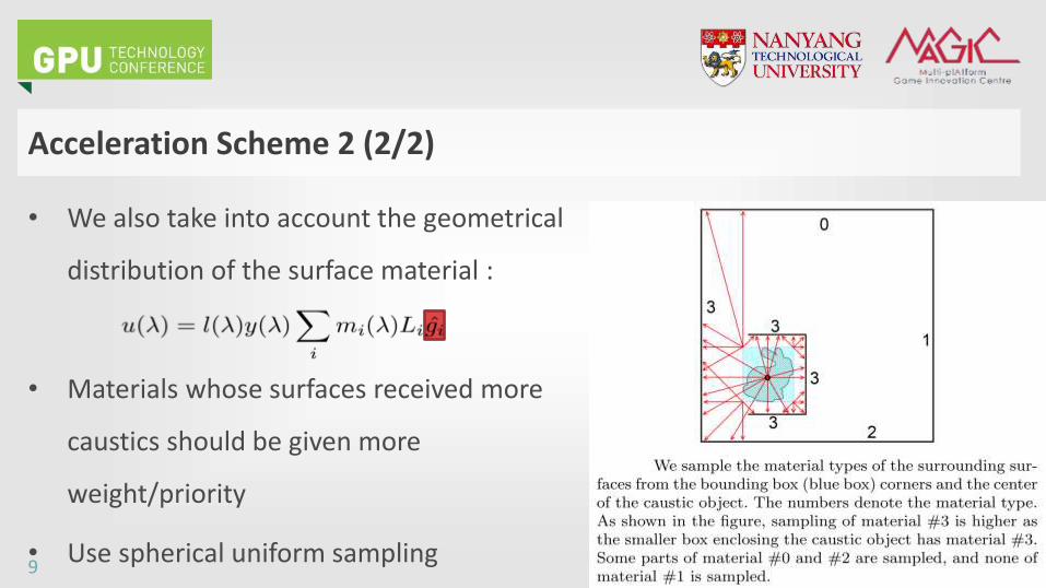
Acceleration Scheme 2 (2/2)
• We also take into account the geometrical
distribution of the surface material :
• Materials whose surfaces received more
caustics should be given more
weight/priority
• Use spherical uniform sampling9
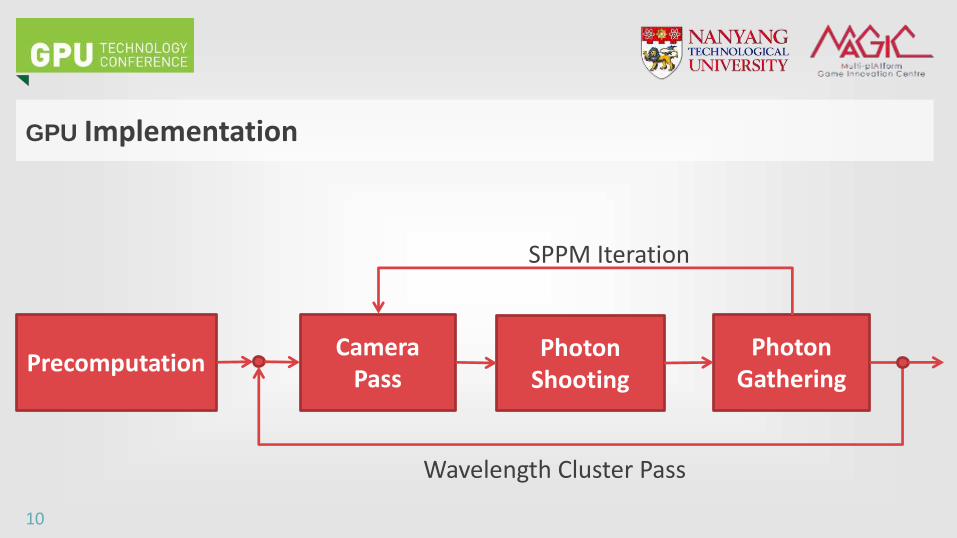
GPU Implementation
10
Camera Pass
Photon Shooting
Photon Gathering
Precomputation
SPPM Iteration
Wavelength Cluster Pass
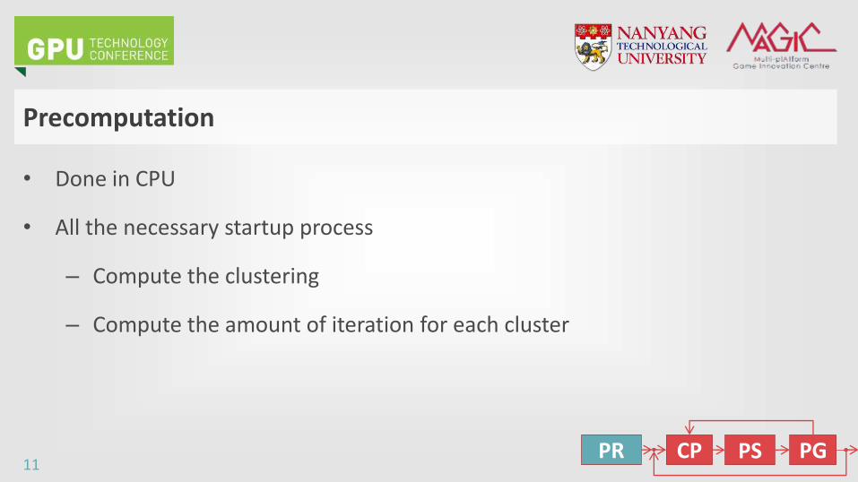
Precomputation
• Done in CPU
• All the necessary startup process
– Compute the clustering
– Compute the amount of iteration for each cluster
11CP PS PGPR
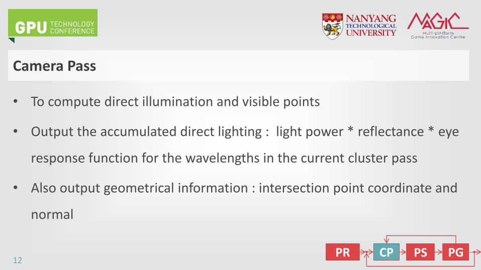
Camera Pass
• To compute direct illumination and visible points
• Output the accumulated direct lighting : light power * reflectance * eye
response function for the wavelengths in the current cluster pass
• Also output geometrical information : intersection point coordinate and
normal
12CP PS PGPR
Photon Shooting Pass
• First pass of indirect illumination computation
• Each photon carries power of the wavelengths in the current cluster pass
• Power of each photon is stored in a ‘flattened’ 2D buffer (to 1D)
– Row = one photon
– Column = one wavelength
13CP PS PGPR
Photon Gathering Pass (1/2)
• Second pass of indirect illumination computation
• A temporary flux buffer to store gathered photon flux
– For each gathered photon, accumulate their flux (multiplied by surface
reflectance) for each wavelength in the current cluster pass
– Row = One visible pixel
– Column = One wavelength
14CP PS PGPR
Photon Gathering Pass (2/2)
• Update the shared accumulated flux (based on the temporary flux of
current iteration and shared accumulated flux) for each wavelength in
the current cluster pass
• To visualize, multiply and accumulate the shared accumulated flux with
eyes response function for each wavelength and combine with the direct
illumination result
15CP PS PGPR
Experiments
• CPU Intel I7-3820 3.60 GHz and GPU : GTX 690 4 GB
• Was implemented in OptiX
– GPU-based ray tracing engine, was built over CUDA
• Maximum iterations for each nm : 2000
• Minimum nm step : 1 nm
• Threshold : 0.1 degree
16
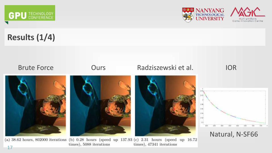
Results (1/4)
Brute Force Ours Radziszewski et al. IOR
Natural, N-SF66
17
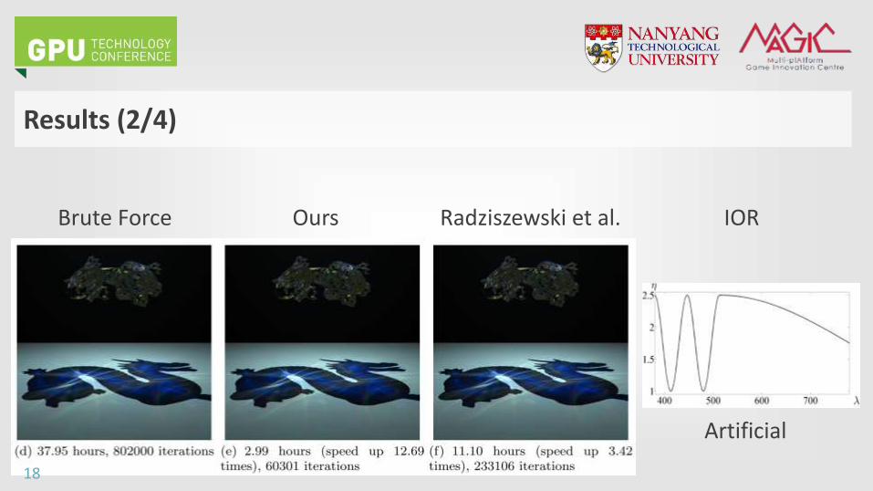
Results (2/4)
Brute Force Ours Radziszewski et al. IOR
Artificial
18
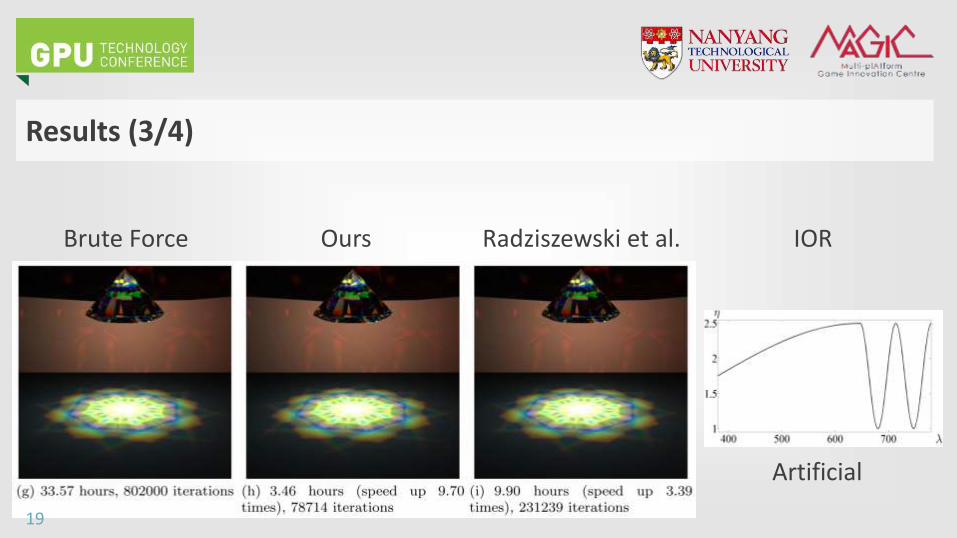
Results (3/4)
Brute Force Ours Radziszewski et al. IOR
Artificial
19
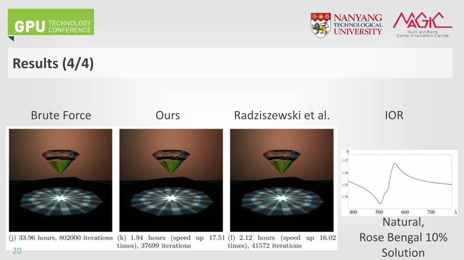
Results (4/4)
Brute Force Ours Radziszewski et al. IOR
Natural, Rose Bengal 10%
Solution20
Application
• Caustic object design and visualization
• Design the caustic object (e.g. a gemstone, crystal vase, glass bracelet, etc.) and
use our method to render it to observe the refraction and caustic effects
• The rendering can be implemented in a renderfarm system, similar to our GPU
renderfarm system presented in GTC 2014 (Season S4356)
21
Conclusion (1/2)
• Main strength of our method :
– Quality of our rendering result is close to Brute Force rendering result
– Also, we achieve rendering speed acceleration with the acceleration
magnitude from tens to thousands
– Compared to Radziszewski et al.’s, we also achieve higher acceleration
22
• Limitations :
– Consider only single type of caustic object IOR
– Not optimized for dynamic scene
Conclusion (2/2)
23
• Handle scene that has multiple caustic objects, each with different index of
refraction
• Sample the surrounding caustic objects by using real-time approximate caustic
renderer
• Apply our acceleration scheme to other rendering algorithms
Future Work
24
• Singapore National Research Foundation under its IDM Futures Funding Initiative
and administered by the Interactive & Digital Media Programme Office, Media
Development Authority
• Ministry of Education Singapore for the Tier-2 research funding support
• Fraunhofer IDM@NTU, which is funded by the National Research Foundation (NRF)
and managed through the multiagency Interactive & Digital Media Programme
Office (IDMPO) hosted by the Media Development Authority of Singapore (MDA).
Acknowledgements
25

Discussion
Please complete the Presenter Evaluation sent to you by email or through the GTC Mobile App. Your feedback is important!
Recommended