Technical Information
H1 Axial Piston Single PumpsSize 147/165
www.danfoss.com
Revision history Table of revisions
Date Changed Rev
May 2018 Angle sensor for EDC; FDC note added. 0801
May 2017 NFPE gen. 3 changes. 0701
November 2015 Master Model Code changes. 0600
September 2014 MDC, CCO, and Swash Angle Sensor options added FA
Mar 2014 Converted to Danfoss layout - DITA CMS EA
Apr 2013 FDC option added DA
Dec 2012 Pressure changed CA
Jul 2010 New EC directive BA
Jul 2009 First edition AA
Technical InformationH1P 147/165 Axial Piston Single Pumps
2 | © Danfoss | May 2018 BC00000061en-US0801
Technical specificationsH1P General Specification.............................................................................................................................................................5H1P 147/165 Technical Data........................................................................................................................................................ 5H1P 147/165 Operating Parameters .........................................................................................................................................6Fluid Specifications .........................................................................................................................................................................7Bearing Life and External Radial Shaft Loads......................................................................................................................... 7H1P 147/165 Mounting Flange Loads ..................................................................................................................................... 8Charge pump..................................................................................................................................................................................... 9
Charge Pump Selection............................................................................................................................................................ 926/34 cm³ Charge Pump – Flow and Power Curves....................................................................................................... 9
Master Model Code
Control OptionsElectrical Displacement Control (EDC)................................................................................................................................... 17
EDC Control Signal Requirements......................................................................................................................................17EDC Solenoid Data................................................................................................................................................................... 18Control Response......................................................................................................................................................................18Response Time, EDC 147/165...............................................................................................................................................19
Manual Displacement Control (MDC) ....................................................................................................................................20MDC Torque................................................................................................................................................................................20MDC General Information..................................................................................................................................................... 20MDC Shaft Rotation................................................................................................................................................................. 21Control Response......................................................................................................................................................................21MDC Response Time................................................................................................................................................................22Neutral Start Switch (NSS)..................................................................................................................................................... 22Case Gauge Port M14..............................................................................................................................................................22Lever..............................................................................................................................................................................................23
Forward-Neutral-Reverse Electric Control (FNR)................................................................................................................ 24Control Response......................................................................................................................................................................25Response Time, FNR 147/165...............................................................................................................................................26
Non Feedback Proportional Electric Control (NFPE)......................................................................................................... 27Control Signal Requirements, NFPE 147/165................................................................................................................. 27Control Response......................................................................................................................................................................28Response Time, NFPE 147/165.............................................................................................................................................29
Automotive Control (AC).............................................................................................................................................................30Mode types................................................................................................................................................................................. 30Basic functions...........................................................................................................................................................................30Performance functions........................................................................................................................................................... 31Protection and safety functions.......................................................................................................................................... 31Engine control and protection.............................................................................................................................................31Installation features................................................................................................................................................................. 31
Fan Drive Control (FDC)............................................................................................................................................................... 32Control Signal Requirements, FDC 147/165................................................................................................................... 32Control Response......................................................................................................................................................................34Response Time, FDC 147/165...............................................................................................................................................34
Manual Over Ride (MOR)............................................................................................................................................................. 35Swash Plate Angle Sensor for EDC Controls.........................................................................................................................36
Swash Plate Angle Sensor Parameters (EDC)..................................................................................................................36Swash Plate Angle Sensor Connector............................................................................................................................... 37Interface with ECU....................................................................................................................................................................37
Swash plate angle sensor for NFPE and AC2 controls...................................................................................................... 38Swash Plate Angle Sensor Parameters (NFPE/AC)........................................................................................................ 38Swash Plate Angle Sensor Connector............................................................................................................................... 39Interface with ECU....................................................................................................................................................................39
Control-Cut-Off valve (CCO valve)........................................................................................................................................... 40CCO solenoid data....................................................................................................................................................................41Brake gauge port with MDC................................................................................................................................................. 41
Displacement limiter.....................................................................................................................................................................42H1P 147/165 Displacement Change (Approximately)................................................................................................ 42
Technical InformationH1P 147/165 Axial Piston Single Pumps
Contents
© Danfoss | May 2018 BC00000061en-US0801 | 3
DimensionsH1P input shaft - Option G2 (SAE D, 27 teeth).....................................................................................................................43H1P input shaft - Option G3 (SAE D, 13 teeth).....................................................................................................................44H1P input shaft - Option F3, Code 44-3................................................................................................................................. 45
Tapered shaft customer acknowledgement...................................................................................................................45H1P 147/165 Auxiliary mounting, option H1 (SAE A, 11 teeth).....................................................................................46H1P 147/165 Auxiliary mounting, option H2 (SAE A, 9 teeth)....................................................................................... 47H1P 147/165 Auxiliary mounting, option H3 (SAE B, 13 teeth)..................................................................................... 48H1P 147/165 Auxiliary mounting, option H4 (SAE D, 13 teeth).................................................................................... 49H1P 147/165 Auxiliary mounting, option H5 (SAE B-B, 15 teeth).................................................................................50H1P 147/165 Auxiliary mounting, option H6 (SAE C, 14 teeth).....................................................................................51H1P 147/165 displacement limiter, option B....................................................................................................................... 52
Installation drawingsPort Description H1P 147/165...................................................................................................................................................53Dimensions H1P 147/165............................................................................................................................................................55
ControlsElectric Displacement Control, Options A2/A3 (12/24 V)................................................................................................ 58Electric Displacement Control with MOR, Options A4/A5 (12/24 V)........................................................................... 58H1P 147/165 Manual Displacement Control (MDC), option M1................................................................................... 59H1P 147/165 Manual Displacement Control (MDC) with NSS, option M2................................................................ 60H1P 147/165 Manual Displacement Control (MDC) with CCO, option M3, M4.......................................................61H1P 147/165 Manual Displacement Control (MDC) with NSS and CCO, option M5, M6..................................... 62Automotive Control (AC) Dimensions....................................................................................................................................63Forward-Neutral-Reverse (FNR) with manual override, options A9 (12 V) / B1 (24 V)...........................................64
FiltrationSuction filtration, option L, H1P 147/165.............................................................................................................................. 65Integral full flow charge pressure filtration with filter bypass sensor, option M, H1P 147/165.........................66
Technical InformationH1P 147/165 Axial Piston Single Pumps
Contents
4 | © Danfoss | May 2018 BC00000061en-US0801
H1P General Specification
Axial piston closed circuit variable displacement pump of cradle swash-plate design with clockwise orcounterclockwise direction of rotation.
Pipe connections
• Main pressure ports: ISO split flange boss• Remaining ports: SAE straight thread O-ring boss
Recommended installation position
Pump installation position is discretionary, however the recommended control position is on the top orat the side with the top position preferred. If the pump is installed with the control at the bottom,flushing flow must be provided through port M14 located on the EDC, FNR and NFPE control.
Vertical input shaft installation is acceptable. If input shaft is at the top, 1 bar case pressure must bemaintained during operation.
The housing must always be filled with hydraulic fluid.
Recommended mounting for a multiple pump stack is to arrange the highest power flow towards theinput source.
Consult Danfoss for nonconformance to these guidelines.
Auxiliary cavity pressure
Auxiliary cavity pressure will be inlet pressure with internal charge pump or case pressure with externalcharge supply. For reference see H1P 147/165 Operating Parameters. Please verify mating pump shaft sealcapability.
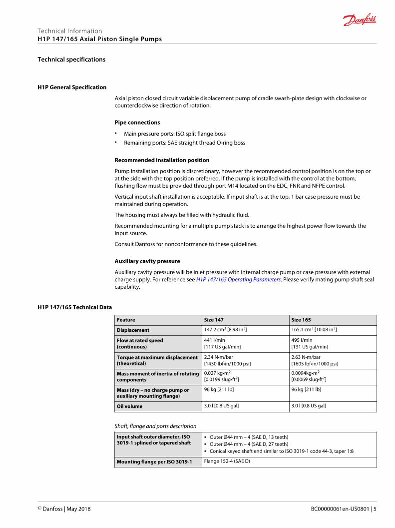
H1P 147/165 Technical Data
Feature Size 147 Size 165
Displacement 147.2 cm3 [8.98 in3] 165.1 cm3 [10.08 in3]
Flow at rated speed(continuous)
441 l/min[117 US gal/min]
495 l/min[131 US gal/min]
Torque at maximum displacement(theoretical)
2.34 N•m/bar[1430 lbf•in/1000 psi]
2.63 N•m/bar[1605 lbf•in/1000 psi]
Mass moment of inertia of rotatingcomponents
0.027 kg•m2
[0.0199 slug•ft2]0.0094kg•m2
[0.0069 slug•ft2]
Mass (dry – no charge pump orauxiliary mounting flange)
96 kg [211 lb] 96 kg [211 lb]
Oil volume 3.0 l [0.8 US gal] 3.0 l [0.8 US gal]
Shaft, flange and ports description
Input shaft outer diameter, ISO3019-1 splined or tapered shaft
• Outer Ø44 mm – 4 (SAE D, 13 teeth)• Outer Ø44 mm – 4 (SAE D, 27 teeth)• Conical keyed shaft end similar to ISO 3019-1 code 44-3, taper 1:8
Mounting flange per ISO 3019-1 Flange 152-4 (SAE D)
Technical InformationH1P 147/165 Axial Piston Single Pumps
Technical specifications
© Danfoss | May 2018 BC00000061en-US0801 | 5
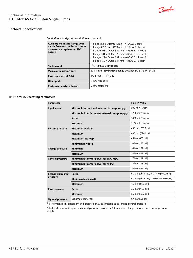
Shaft, flange and ports description (continued)
Auxiliary mounting flange withmetric fasteners, with shaft outerdiameter and splines per ISO3019-1
• Flange 82-2 Outer Ø16 mm – 4 (SAE A, 9 teeth)• Flange 82-2 Outer Ø19 mm – 4 (SAE A, 11 teeth)• Flange 101-2 Outer Ø22 mm – 4 (SAE B, 13 teeth)• Flange 101-2 Outer Ø25 mm – 4 (SAE B-B, 15 teeth)• Flange 127-4 Outer Ø32 mm – 4 (SAE C, 14 teeth)• Flange 152-4 Outer Ø44 mm – 4 (SAE D, 13 teeth)
Suction port 1 5∕8 -12 (SAE O-ring boss)
Main configuration port Ø31.5 mm - 450 bar split flange boss per ISO 6162, M12x1.75
Case drain ports L2, L4 ISO 11926-1 – 15∕16–12
Other ports SAE O-ring boss
Customer interface threads Metric fasteners
H1P 147/165 Operating Parameters
Parameter Size 147/165
Input speed Min. for internal1) and external2) charge supply 500 min-1 (rpm)
Min. for full performance, internal charge supply 1200 min-1 (rpm)
Rated 3000 min-1 (rpm)
Maximum 3100 min-1 (rpm)
System pressure Maximum working 450 bar [6528 psi]
Maximum 480 bar [6960 psi]
Maximum low loop 45 bar [650 psi]
Minimum low loop 10 bar [145 psi]
Charge pressure Minimum 16 bar [232 psi]
Maximum 34 bar [493 psi]
Control pressure Minimum (at corner power for EDC, MDC) 17 bar [247 psi]
Minimum (at corner power for NFPE) 25 bar [363 psi]
Maximum 34 bar [493 psi]
Charge pump inletpressure
Rated 0.7 bar (absolute) [9.0 in Hg vacuum]
Minimum (cold start) 0.2 bar (absolute) [24.0 in Hg vacuum]
Maximum 4.0 bar [58.0 psi]
Case pressure Rated 3.0 bar [44.0 psi]
Maximum 5.0 bar [73.0 psi]
Lip seal pressure Maximum (external) 0.4 bar [5.8 psi]
1) Performance (displacement and pressure) may be limited due to limited control pressure.2) Full performance (displacement and pressure) possible at (at minimum charge pressure and control pressuresupply.
Technical InformationH1P 147/165 Axial Piston Single Pumps
Technical specifications
6 | © Danfoss | May 2018 BC00000061en-US0801
Fluid Specifications
Viscosity
Intermittent1) Minimum Recommended range Maximum
5 mm2/s [42 SUS] 7 mm2/s [49 SUS] 12 – 80 mm2/s [66 – 370 SUS] 1600 mm2/s [7500 SUS]1) Intermittent = Short term t < 1 min per incident and not exceeding 2 % of duty cycle based load-life
Temperature
Minimum (cold start) Rated Recommended range* Maximum Intermittent1)
-40°C [-40°F] 104°C [220°F] 60 – 85°C [140 – 185°F] 115°C [240°F]* At the hottest point, normally case drain port
Filtration, Cleanliness level and Efficiency βx-ratio ( Recommended Minimum)
Cleanliness per ISO 4406 22/18/13
Efficiency βx (charge pressure filtration) β15-20 = 75 (β10 ≥ 10)
Efficiency βx (suction and return line filtration) β35-45 = 75 (β10 ≥ 2)
Recommended inlet screen mesh size 100 – 125 µm
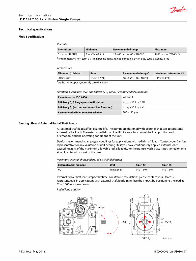
Bearing Life and External Radial Shaft Loads
All external shaft loads affect bearing life. The pumps are designed with bearings that can accept someexternal radial loads. The external radial shaft load limits are a function of the load position andorientation, and the operating conditions of the unit.
Danfoss recommends clamp-type couplings for applications with radial shaft loads. Contact your Danfossrepresentative for an evaluation of unit bearing life if you have continuously applied external loadsexceeding 25 % of the maximum allowable radial load (Re) or the pump swash-plate is positioned on oneside of center all or most of the time.
Maximum external shaft load based on shaft deflection
External radial moment Unit Size 147 Size 165
Me N•m [lbf•in] 140 [1240] 140 [1240]
External radial shaft loads impact lifetime. For lifetime calculations please contact your Danfossrepresentative. In applications with external shaft loads, minimize the impact by positioning the load at0° or 180° as shown below.
Radial load position
P003 318E
L
270° Re
Re
Me
180° Re
90° Re
0° Re
Technical InformationH1P 147/165 Axial Piston Single Pumps
Technical specifications
© Danfoss | May 2018 BC00000061en-US0801 | 7
The maximum allowable radial shaft load (Re) is based on the maximum external moment (Me) and thedistance (L) from the mounting flange to the load. It may be determined using the following formula:
Re = Me L
Thrust loads should be avoided. Contact your Danfoss representative in the event thrust loads areanticipated.
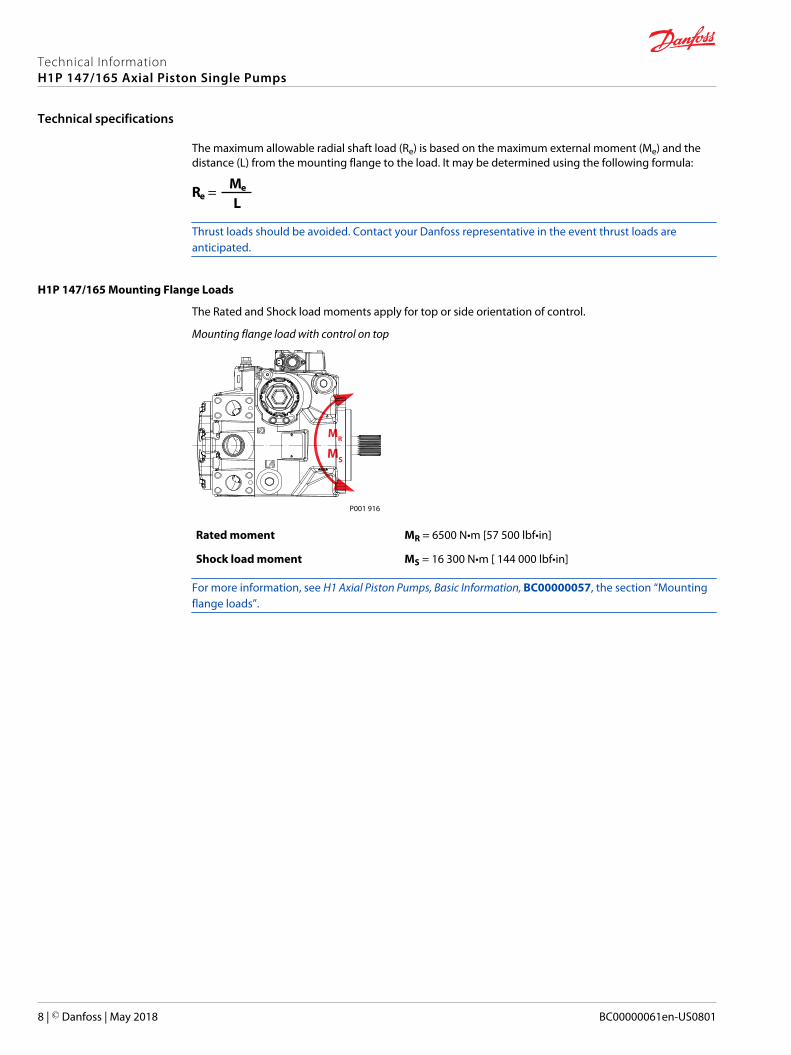
H1P 147/165 Mounting Flange Loads
The Rated and Shock load moments apply for top or side orientation of control.
Mounting flange load with control on top
P001 916
MR
MS
Rated moment MR = 6500 N•m [57 500 lbf•in]
Shock load moment MS = 16 300 N•m [ 144 000 lbf•in]
For more information, see H1 Axial Piston Pumps, Basic Information, BC00000057, the section “Mountingflange loads”.
Technical InformationH1P 147/165 Axial Piston Single Pumps
Technical specifications
8 | © Danfoss | May 2018 BC00000061en-US0801
Charge pump
Charge Pump Selection
In most applications a general guideline is that the charge pump displacement should be at least 10% ofthe total displacement of all components in the system. Unusual application conditions may require amore detailed review of charge flow requirements. System features and conditions which may invalidatethe 10% guideline include (but are not limited to):• Continuous operation at low input speeds < 1500 min-1 (rpm)
• High shock loading and/or long loop lines
• High flushing flow requirements
• Multiple low speed high torque motors
• High input shaft speeds
Contact your Danfoss representative for application assistance if your application includes any of theseconditions.
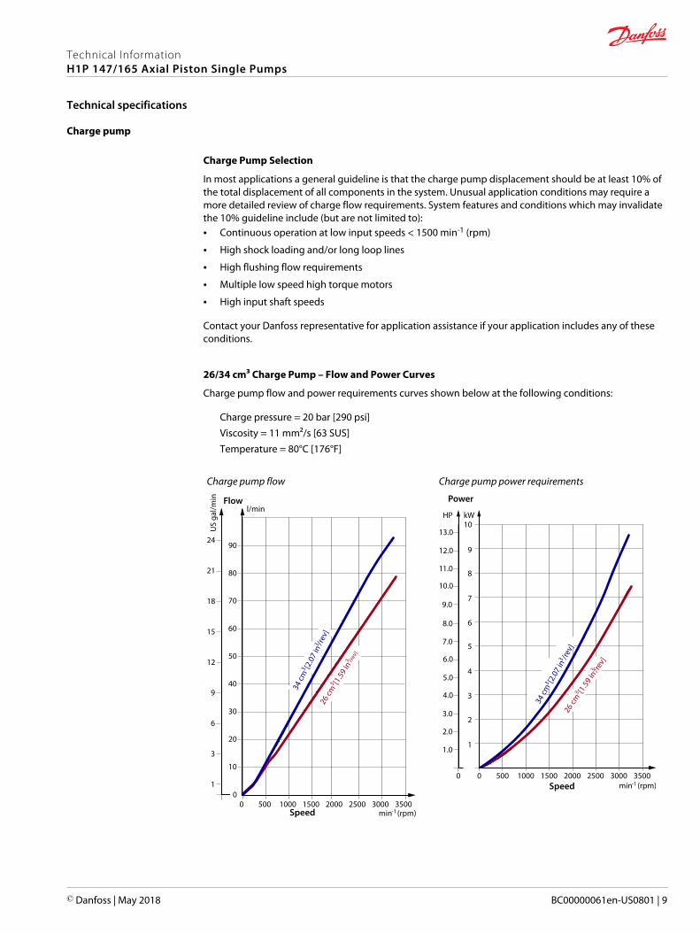
26/34 cm³ Charge Pump – Flow and Power Curves
Charge pump flow and power requirements curves shown below at the following conditions:
Charge pressure = 20 bar [290 psi]Viscosity = 11 mm²/s [63 SUS]Temperature = 80°C [176°F]
Charge pump flow
0 500 15001000 2000 30002500 3500
24
21
18
15
12
9
6
3
1
90
80
70
60
50
40
30
20
10
0
l/min
US
gal/m
in
34 cm
3 [2.0
7 in
3 /rev]
26 cm
3 [1.59
in3 /re
v]
Speed
Flow
min-1 (rpm)
Charge pump power requirements
10
9
8
7
6
5
4
3
2
1
0
13.0
12.0
11.0
10.0
9.0
8.0
7.0
6.0
5.0
4.0
3.0
2.0
1.0
HP kW
34 cm
3 [2.0
7 in
3 /rev]
26 cm
3 [1.59
in3 /re
v]
0 500 15001000 2000 min-1 (rpm)
30002500 3500Speed
Power
Technical InformationH1P 147/165 Axial Piston Single Pumps
Technical specifications
© Danfoss | May 2018 BC00000061en-US0801 | 9
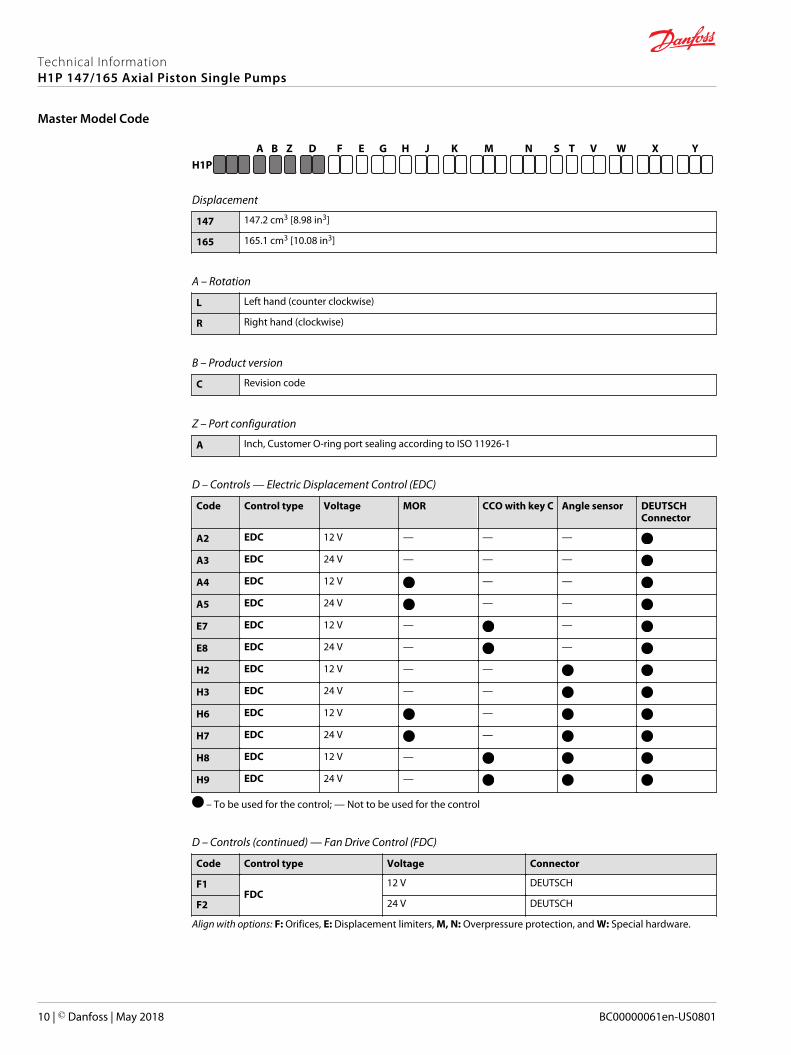
G H J K M N S T V W X YZ D EFH1P
A B
Displacement
147 147.2 cm3 [8.98 in3]
165 165.1 cm3 [10.08 in3]
A – Rotation
L Left hand (counter clockwise)
R Right hand (clockwise)
B – Product version
C Revision code
Z – Port configuration
A Inch, Customer O-ring port sealing according to ISO 11926-1
D – Controls — Electric Displacement Control (EDC)
Code Control type Voltage MOR CCO with key C Angle sensor DEUTSCHConnector
A2 EDC 12 V — — —
A3 EDC 24 V — — —
A4 EDC 12 V — —
A5 EDC 24 V — —
E7 EDC 12 V — —
E8 EDC 24 V — —
H2 EDC 12 V — —
H3 EDC 24 V — —
H6 EDC 12 V —
H7 EDC 24 V —
H8 EDC 12 V —
H9 EDC 24 V —
– To be used for the control; — Not to be used for the control
D – Controls (continued) — Fan Drive Control (FDC)
Code Control type Voltage Connector
F1FDC
12 V DEUTSCH
F2 24 V DEUTSCH
Align with options: F: Orifices, E: Displacement limiters, M, N: Overpressure protection, and W: Special hardware.
Technical InformationH1P 147/165 Axial Piston Single Pumps
Master Model Code
10 | © Danfoss | May 2018 BC00000061en-US0801
G H J K M N S T V W X YZ D EFH1P
A B
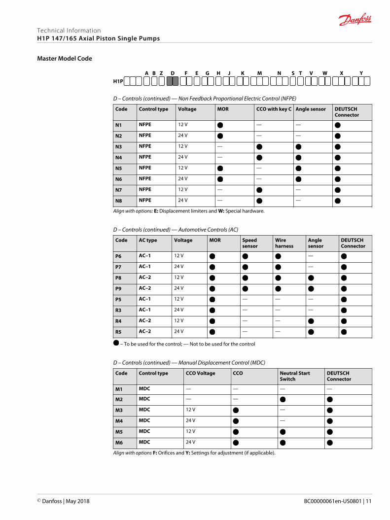
D – Controls (continued) — Non Feedback Proportional Electric Control (NFPE)
Code Control type Voltage MOR CCO with key C Angle sensor DEUTSCHConnector
N1 NFPE 12 V — —
N2 NFPE 24 V — —
N3 NFPE 12 V —
N4 NFPE 24 V —
N5 NFPE 12 V —
N6 NFPE 24 V —
N7 NFPE 12 V — —
N8 NFPE 24 V — —
Align with options: E: Displacement limiters and W: Special hardware.
D – Controls (continued) — Automotive Controls (AC)
Code AC type Voltage MOR Speedsensor
Wireharness
Anglesensor
DEUTSCHConnector
P6 AC–1 12 V —
P7 AC–1 24 V —
P8 AC–2 12 V
P9 AC–2 24 V
P5 AC–1 12 V — — —
R3 AC–1 24 V — — —
R4 AC–2 12 V — —
R5 AC–2 24 V — —
– To be used for the control; — Not to be used for the control
D – Controls (continued) — Manual Displacement Control (MDC)
Code Control type CCO Voltage CCO Neutral StartSwitch
DEUTSCHConnector
M1 MDC — — — —
M2 MDC — —
M3 MDC 12 V —
M4 MDC 24 V —
M5 MDC 12 V
M6 MDC 24 V
Align with options F: Orifices and Y: Settings for adjustment (if applicable).
Technical InformationH1P 147/165 Axial Piston Single Pumps
Master Model Code
© Danfoss | May 2018 BC00000061en-US0801 | 11
G H J K M N S T V W X YZ D EFH1P
A B
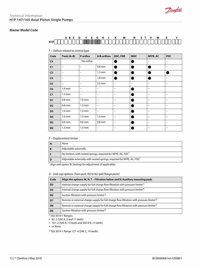
F – Orifices related to control type
Code Tank (A+B) P orifice A/B orifices EDC, FNR MDC NFPE, AC FDC
C3 No orifice – –
C1 – – 0.8 mm –
C2 – – 1.3 mm
C4 – – 1.8 mm –
C5 – – 2.5 mm – – – –
C6 1.0 mm – – – –
C7 1.3 mm – – – – –
D1 0.8 mm 1.0 mm – – – –
D2 0.8 mm 1.3 mm – – – –
D3 1.0 mm 1.3 mm – – – –
D4 1.0 mm 1.3 mm 1.3 mm – – –
D5 0.6 mm 0.6 mm 0.8 mm – – –
D6 1.3 mm 1.3 mm – – – –
E – Displacement limiter
N None
B Adjustable externally
C No limiters, with nested springs, required for NFPE, AC, FDC*
D Adjustable externally with nested springs, required for NFPE, AC, FDC*
* Align with option Y: Settings for adjustment (if applicable).
G – End-cap options (Twin port, ISO 6162 split flange ports)
Code Align the options: M, N, T – Filtration below and K: Auxiliary mounting pads
D3 Internal charge supply for full charge flow filtration with pressure limiter1)
D5 Internal charge supply for full charge flow filtration with pressure limiter2)
D6 Suction filtration with pressure limiter1)
D7 Remote or external charge supply for full charge flow filtration with pressure limiter2)
D8 Remote or external charge supply for full charge flow filtration with pressure limiter1)
D9 Suction filtration with pressure limiter2)
1) ISO 3019-1 flanges:• 82–2 (SAE A, 9 and 11 teeth)• 101–2 (SAE B, 13 teeth and SAE B-B, 15 teeth)• or None2) ISO 3019-1 flange 127–4 (SAE C, 14 teeth)
Technical InformationH1P 147/165 Axial Piston Single Pumps
Master Model Code
12 | © Danfoss | May 2018 BC00000061en-US0801
G H J K M N S T V W X YZ D EFH1P
A B
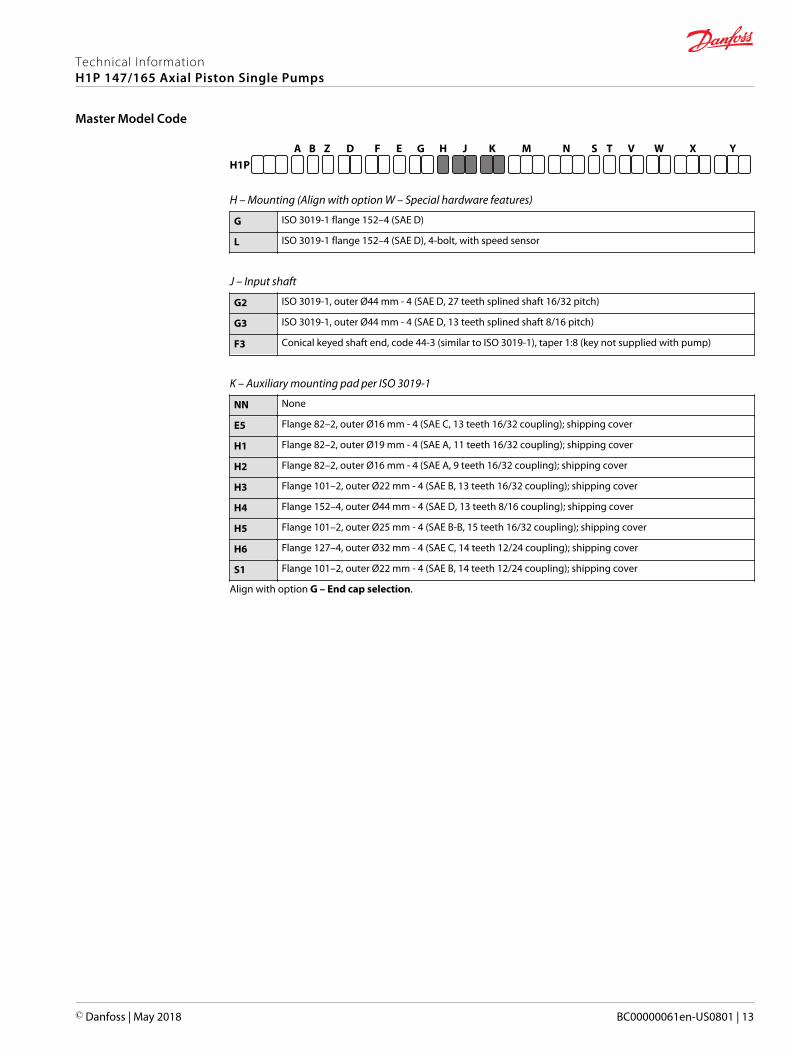
H – Mounting (Align with option W – Special hardware features)
G ISO 3019-1 flange 152–4 (SAE D)
L ISO 3019-1 flange 152–4 (SAE D), 4-bolt, with speed sensor
J – Input shaft
G2 ISO 3019-1, outer Ø44 mm - 4 (SAE D, 27 teeth splined shaft 16/32 pitch)
G3 ISO 3019-1, outer Ø44 mm - 4 (SAE D, 13 teeth splined shaft 8/16 pitch)
F3 Conical keyed shaft end, code 44-3 (similar to ISO 3019-1), taper 1:8 (key not supplied with pump)
K – Auxiliary mounting pad per ISO 3019-1
NN None
E5 Flange 82–2, outer Ø16 mm - 4 (SAE C, 13 teeth 16/32 coupling); shipping cover
H1 Flange 82–2, outer Ø19 mm - 4 (SAE A, 11 teeth 16/32 coupling); shipping cover
H2 Flange 82–2, outer Ø16 mm - 4 (SAE A, 9 teeth 16/32 coupling); shipping cover
H3 Flange 101–2, outer Ø22 mm - 4 (SAE B, 13 teeth 16/32 coupling); shipping cover
H4 Flange 152–4, outer Ø44 mm - 4 (SAE D, 13 teeth 8/16 coupling); shipping cover
H5 Flange 101–2, outer Ø25 mm - 4 (SAE B-B, 15 teeth 16/32 coupling); shipping cover
H6 Flange 127–4, outer Ø32 mm - 4 (SAE C, 14 teeth 12/24 coupling); shipping cover
S1 Flange 101–2, outer Ø22 mm - 4 (SAE B, 14 teeth 12/24 coupling); shipping cover
Align with option G – End cap selection.
Technical InformationH1P 147/165 Axial Piston Single Pumps
Master Model Code
© Danfoss | May 2018 BC00000061en-US0801 | 13
G H J K M N S T V W X YZ D EFH1P
A B
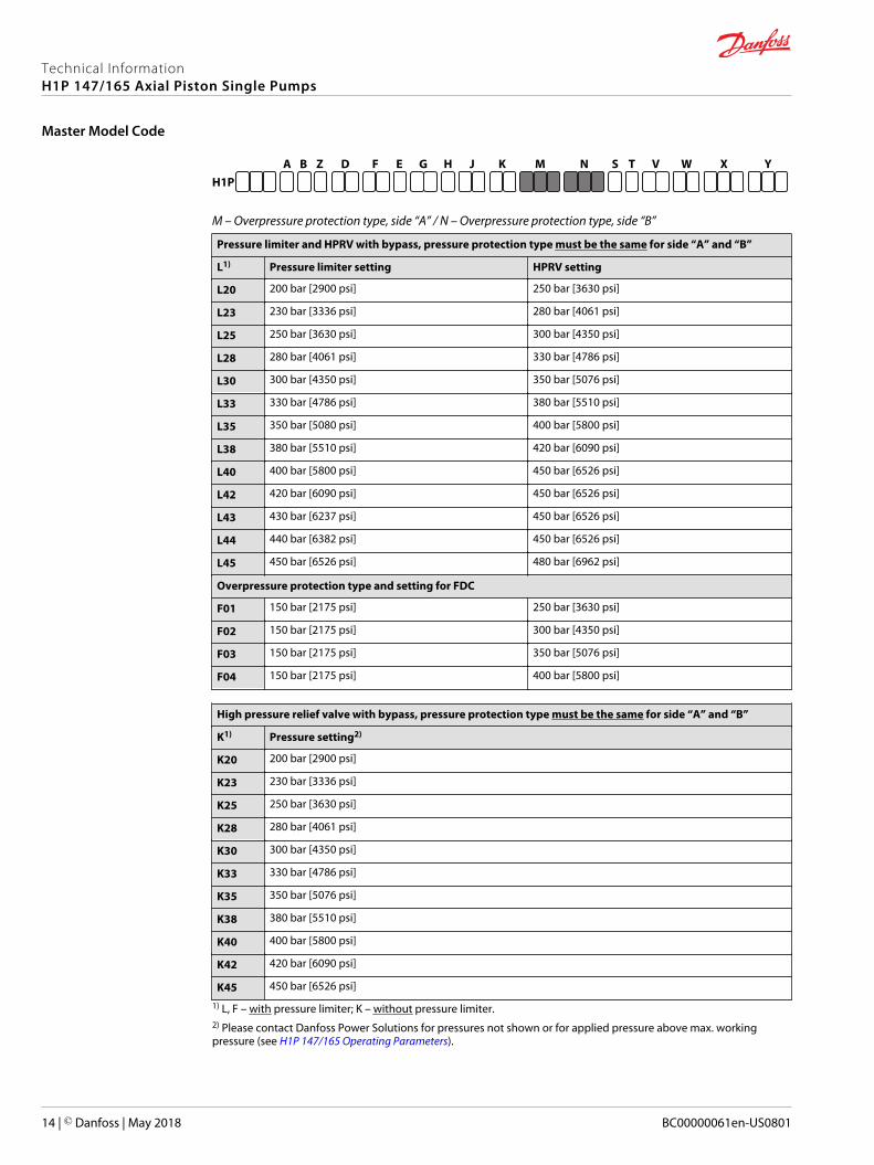
M – Overpressure protection type, side “A” / N – Overpressure protection type, side “B”
Pressure limiter and HPRV with bypass, pressure protection type must be the same for side “A” and “B”
L1) Pressure limiter setting HPRV setting
L20 200 bar [2900 psi] 250 bar [3630 psi]
L23 230 bar [3336 psi] 280 bar [4061 psi]
L25 250 bar [3630 psi] 300 bar [4350 psi]
L28 280 bar [4061 psi] 330 bar [4786 psi]
L30 300 bar [4350 psi] 350 bar [5076 psi]
L33 330 bar [4786 psi] 380 bar [5510 psi]
L35 350 bar [5080 psi] 400 bar [5800 psi]
L38 380 bar [5510 psi] 420 bar [6090 psi]
L40 400 bar [5800 psi] 450 bar [6526 psi]
L42 420 bar [6090 psi] 450 bar [6526 psi]
L43 430 bar [6237 psi] 450 bar [6526 psi]
L44 440 bar [6382 psi] 450 bar [6526 psi]
L45 450 bar [6526 psi] 480 bar [6962 psi]
Overpressure protection type and setting for FDC
F01 150 bar [2175 psi] 250 bar [3630 psi]
F02 150 bar [2175 psi] 300 bar [4350 psi]
F03 150 bar [2175 psi] 350 bar [5076 psi]
F04 150 bar [2175 psi] 400 bar [5800 psi]
High pressure relief valve with bypass, pressure protection type must be the same for side “A” and “B”
K1) Pressure setting2)
K20 200 bar [2900 psi]
K23 230 bar [3336 psi]
K25 250 bar [3630 psi]
K28 280 bar [4061 psi]
K30 300 bar [4350 psi]
K33 330 bar [4786 psi]
K35 350 bar [5076 psi]
K38 380 bar [5510 psi]
K40 400 bar [5800 psi]
K42 420 bar [6090 psi]
K45 450 bar [6526 psi]
1) L, F – with pressure limiter; K – without pressure limiter.2) Please contact Danfoss Power Solutions for pressures not shown or for applied pressure above max. workingpressure (see H1P 147/165 Operating Parameters).
Technical InformationH1P 147/165 Axial Piston Single Pumps
Master Model Code
14 | © Danfoss | May 2018 BC00000061en-US0801
G H J K M N S T V W X YZ D EFH1P
A B
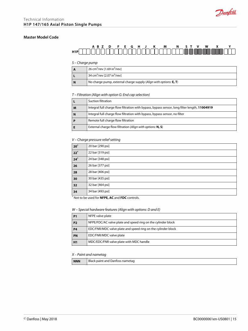
S – Charge pump
A 26 cm³/rev [1.69 in³/rev]
L 34 cm³/rev [2.07 in³/rev]
N No charge pump, external charge supply (Align with options: E, T)
T – Filtration (Align with option G: End cap selection)
L Suction filtration
M Integral full charge flow filtration with bypass, bypass sensor, long filter length, 11004919
N Integral full charge flow filtration with bypass, bypass sensor, no filter
P Remote full charge flow filtration
E External charge flow filtration (Align with options: N, S)
V – Charge pressure relief setting
20* 20 bar [290 psi]
22* 22 bar [319 psi]
24* 24 bar [348 psi]
26 26 bar [377 psi]
28 28 bar [406 psi]
30 30 bar [435 psi]
32 32 bar [464 psi]
34 34 bar [493 psi]
* Not to be used for NFPE, AC and FDC controls.
W – Special hardware features (Align with options: D and E)
P1 NFPE valve plate
P2 NFPE/FDC/AC valve plate and speed ring on the cylinder block
P4 EDC/FNR/MDC valve plate and speed ring on the cylinder block
PN EDC/FNR/MDC valve plate
H1 MDC/EDC/FNR valve plate with MDC handle
X – Paint and nametag
NNN Black paint and Danfoss nametag
Technical InformationH1P 147/165 Axial Piston Single Pumps
Master Model Code
© Danfoss | May 2018 BC00000061en-US0801 | 15
G H J K M N S T V W X YZ D EFH1P
A B
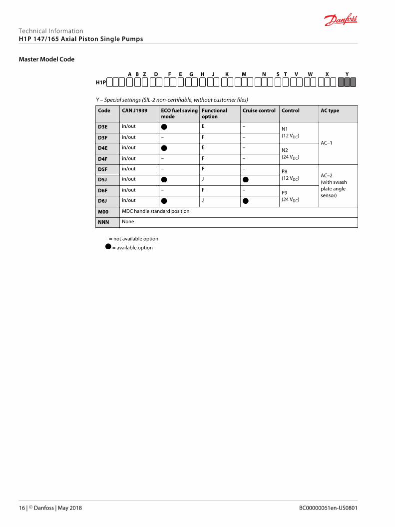
Y – Special settings (SIL-2 non-certifiable, without customer files)
Code CAN J1939 ECO fuel savingmode
Functionaloption
Cruise control Control AC type
D3E in/out E – N1(12 VDC)
AC–1D3F in/out – F –
D4E in/out E – N2(24 VDC)D4F in/out – F –
D5F in/out – F – P8(12 VDC) AC–2
(with swashplate anglesensor)
D5J in/out J
D6F in/out – F – P9(24 VDC)D6J in/out J
M00 MDC handle standard position
NNN None
– = not available option
= available option
Technical InformationH1P 147/165 Axial Piston Single Pumps
Master Model Code
16 | © Danfoss | May 2018 BC00000061en-US0801
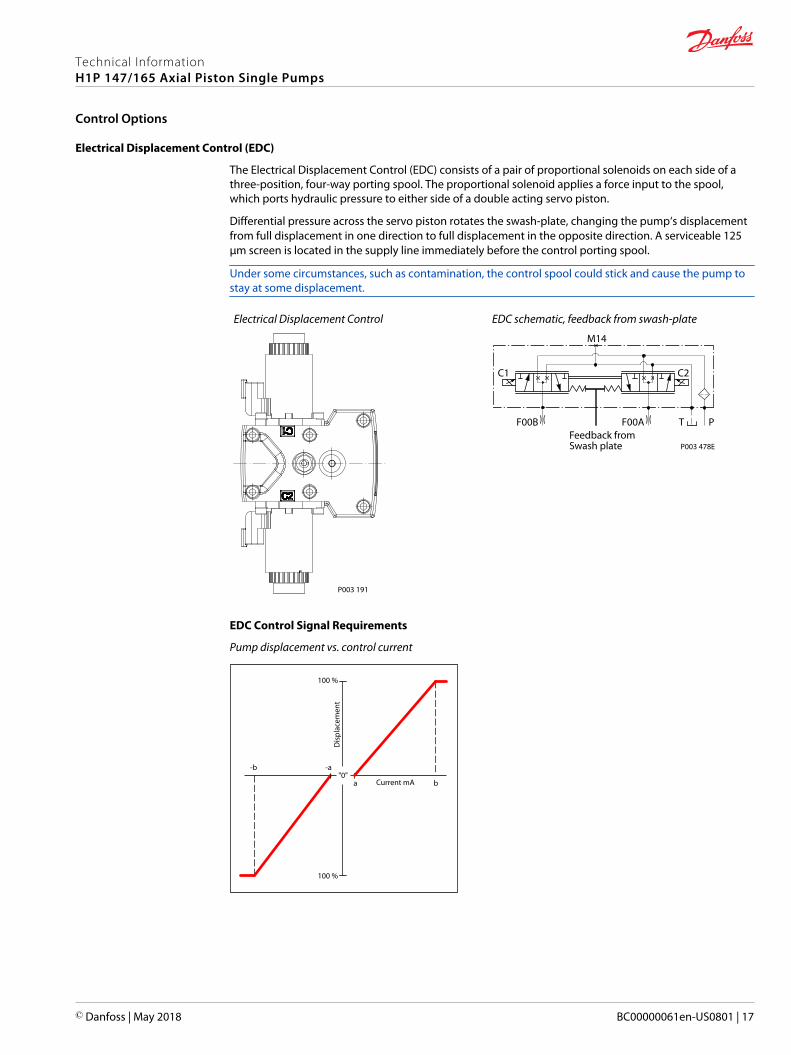
Electrical Displacement Control (EDC)
The Electrical Displacement Control (EDC) consists of a pair of proportional solenoids on each side of athree-position, four-way porting spool. The proportional solenoid applies a force input to the spool,which ports hydraulic pressure to either side of a double acting servo piston.
Differential pressure across the servo piston rotates the swash-plate, changing the pump‘s displacementfrom full displacement in one direction to full displacement in the opposite direction. A serviceable 125μm screen is located in the supply line immediately before the control porting spool.
Under some circumstances, such as contamination, the control spool could stick and cause the pump tostay at some displacement.
Electrical Displacement Control
P003 191
EDC schematic, feedback from swash-plate
Feedback from Swash plate
PTF00B
M14
C1 C2
F00A
P003 478E
EDC Control Signal Requirements
Pump displacement vs. control current
"0"-b -a
ba
100 %
100 %
Dis
plac
emen
t
Current mA
Technical InformationH1P 147/165 Axial Piston Single Pumps
Control Options
© Danfoss | May 2018 BC00000061en-US0801 | 17
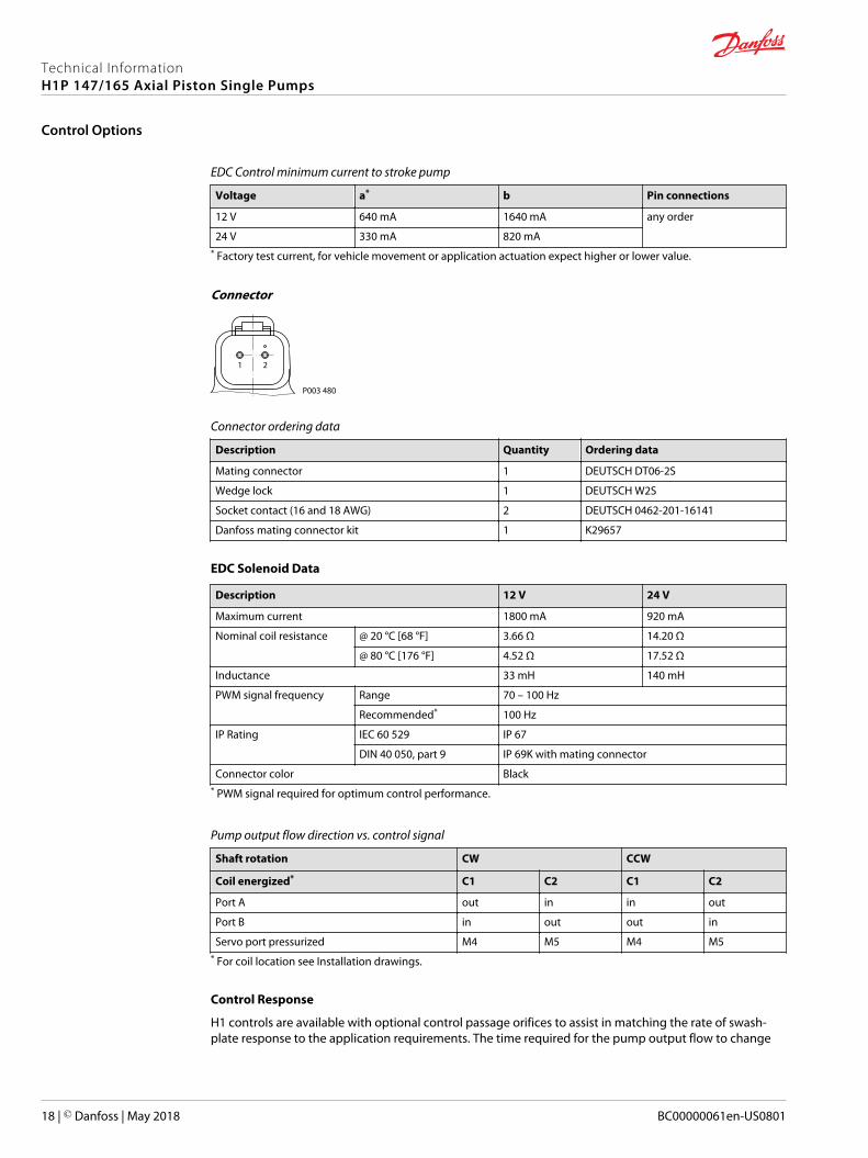
EDC Control minimum current to stroke pump
Voltage a* b Pin connections
12 V 640 mA 1640 mA any order
24 V 330 mA 820 mA* Factory test current, for vehicle movement or application actuation expect higher or lower value.
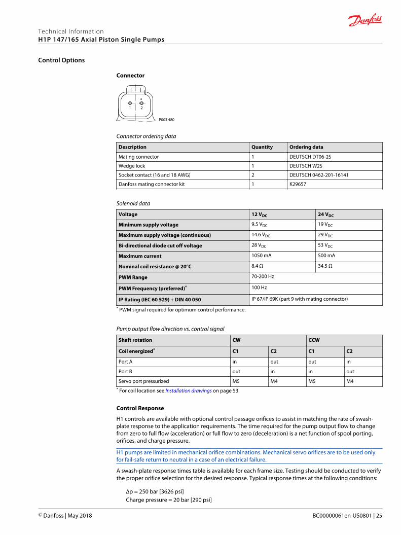
Connector
1 2
P003 480
Connector ordering data
Description Quantity Ordering data
Mating connector 1 DEUTSCH DT06-2S
Wedge lock 1 DEUTSCH W2S
Socket contact (16 and 18 AWG) 2 DEUTSCH 0462-201-16141
Danfoss mating connector kit 1 K29657
EDC Solenoid Data
Description 12 V 24 V
Maximum current 1800 mA 920 mA
Nominal coil resistance @ 20 °C [68 °F] 3.66 Ω 14.20 Ω
@ 80 °C [176 °F] 4.52 Ω 17.52 Ω
Inductance 33 mH 140 mH
PWM signal frequency Range 70 – 100 Hz
Recommended* 100 Hz
IP Rating IEC 60 529 IP 67
DIN 40 050, part 9 IP 69K with mating connector
Connector color Black* PWM signal required for optimum control performance.
Pump output flow direction vs. control signal
Shaft rotation CW CCW
Coil energized* C1 C2 C1 C2
Port A out in in out
Port B in out out in
Servo port pressurized M4 M5 M4 M5* For coil location see Installation drawings.
Control Response
H1 controls are available with optional control passage orifices to assist in matching the rate of swash-plate response to the application requirements. The time required for the pump output flow to change
Technical InformationH1P 147/165 Axial Piston Single Pumps
Control Options
18 | © Danfoss | May 2018 BC00000061en-US0801
from zero to full flow (acceleration) or full flow to zero (deceleration) is a net function of spool porting,orifices, and charge pressure.
H1 pumps are limited in mechanical orifice combinations. Mechanical servo orifices are to be used onlyfor fail-safe return to neutral in a case of an electrical failure.
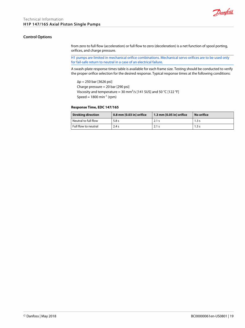
A swash-plate response times table is available for each frame size. Testing should be conducted to verifythe proper orifice selection for the desired response. Typical response times at the following conditions:
∆p = 250 bar [3626 psi]Charge pressure = 20 bar [290 psi]Viscosity and temperature = 30 mm²/s [141 SUS] and 50 °C [122 °F]Speed = 1800 min-1 (rpm)
Response Time, EDC 147/165
Stroking direction 0.8 mm [0.03 in] orifice 1.3 mm [0.05 in] orifice No orifice
Neutral to full flow 5.8 s 2.1 s 1.3 s
Full flow to neutral 2.4 s 2.1 s 1.3 s
Technical InformationH1P 147/165 Axial Piston Single Pumps
Control Options
© Danfoss | May 2018 BC00000061en-US0801 | 19
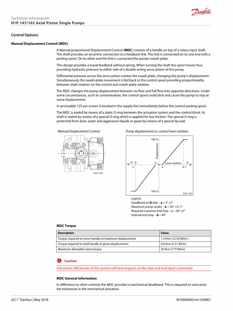
Manual Displacement Control (MDC)
A Manual proportional Displacement Control (MDC) consists of a handle on top of a rotary input shaft.The shaft provides an eccentric connection to a feedback link. This link is connected on its one end with aporting spool. On its other end the link is connected the pumps swash-plate.
This design provides a travel feedback without spring. When turning the shaft the spool moves thusproviding hydraulic pressure to either side of a double acting servo piston of the pump.
Differential pressure across the servo piston rotates the swash plate, changing the pump’s displacement.Simultaneously the swash-plate movement is fed back to the control spool providing proportionalitybetween shaft rotation on the control and swash-plate rotation.
The MDC changes the pump displacement between no flow and full flow into opposite directions. Undersome circumstances, such as contamination, the control spool could stick and cause the pump to stay atsome displacement.
A serviceable 125 μm screen is located in the supply line immediately before the control porting spool.
The MDC is sealed by means of a static O-ring between the actuation system and the control block. Itsshaft is sealed by means of a special O-ring which is applied for low friction. The special O-ring isprotected from dust, water and aggressive liquids or gases by means of a special lip seal.
Manual Displacement Control
P301 749
Pump displacement vs. control lever rotation
"0"Lever rotation"A"
Dis
plac
emen
t
100 %
a
-a
100 %
"B"-b-d
b c
d
-c
P301 752
Legend:Deadband on B side – a = 3° ±1°Maximum pump stroke – b = 30° +2/-1°Required customer end stop – c = 36° ±3°Internal end stop – d = 40°
MDC Torque
Description Value
Torque required to move handle to maximum displacement 1.4 N•m [12.39 lbf•in ]
Torque required to hold handle at given displacement 0.6 N•m [5.31 lbf•in]
Maximum allowable input torque 20 N•m [177 lbf•in]
C Caution
Volumetric efficiencies of the system will have impacts on the start and end input commands.
MDC General Information
In difference to other controls the MDC provides a mechanical deadband. This is required to overcomethe tolerances in the mechanical actuation.
Technical InformationH1P 147/165 Axial Piston Single Pumps
Control Options
20 | © Danfoss | May 2018 BC00000061en-US0801
The MDC contains an internal end stop to prevent over travel. The restoring moment is appropriate forturning the MDC input shaft back to neutral only. Any linkages or cables may prevent the MDC fromreturning to neutral.
The MDC is designed for a maximum case pressure of 5 bar and a rated case pressure of 3 bar. If the casepressure exceeds 5 bar there is a risk of an insufficient restoring moment. In addition a high case pressurecan cause the NSS to indicate that the control is not in neutral. High case pressure may cause excessivewear.
Customers can apply their own handle design but they must care about a robust clamping connectionbetween their handle and the control shaft and avoid overload of the shaft.
Customers can connect two MDC’s on a tandem unit in such a way that the actuation force will betransferred from the pilot control to the second control but the kinematic of the linkages must ensurethat either control shaft is protected from torque overload. To avoid an overload of the MDC, customersmust install any support to limit the setting range of the Bowden cable.
C Caution
Using the internal spring force on the input shaft is not an appropriate way to return the customerconnection linkage to neutral.
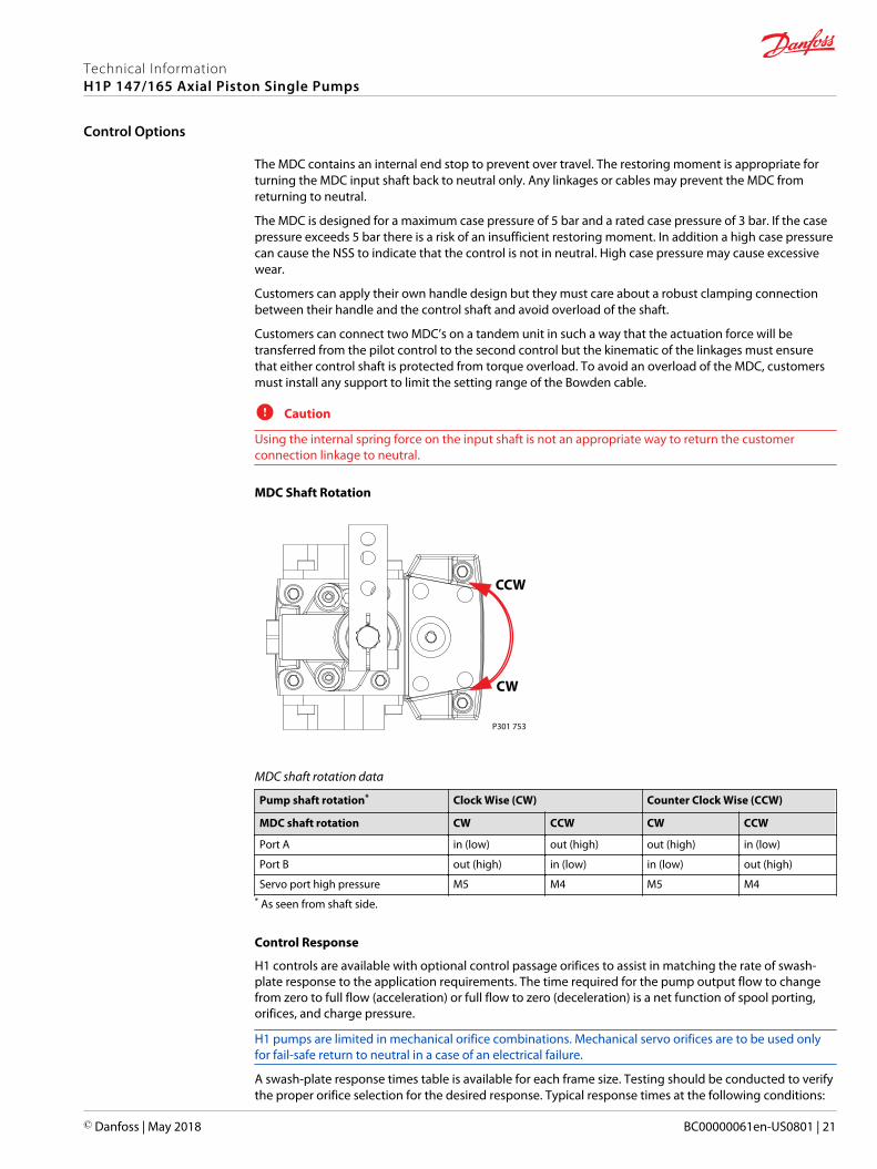
MDC Shaft Rotation
CCW
CW
P301 753
MDC shaft rotation data
Pump shaft rotation* Clock Wise (CW) Counter Clock Wise (CCW)
MDC shaft rotation CW CCW CW CCW
Port A in (low) out (high) out (high) in (low)
Port B out (high) in (low) in (low) out (high)
Servo port high pressure M5 M4 M5 M4* As seen from shaft side.
Control Response
H1 controls are available with optional control passage orifices to assist in matching the rate of swash-plate response to the application requirements. The time required for the pump output flow to changefrom zero to full flow (acceleration) or full flow to zero (deceleration) is a net function of spool porting,orifices, and charge pressure.
H1 pumps are limited in mechanical orifice combinations. Mechanical servo orifices are to be used onlyfor fail-safe return to neutral in a case of an electrical failure.
A swash-plate response times table is available for each frame size. Testing should be conducted to verifythe proper orifice selection for the desired response. Typical response times at the following conditions:
Technical InformationH1P 147/165 Axial Piston Single Pumps
Control Options
© Danfoss | May 2018 BC00000061en-US0801 | 21
∆p = 250 bar [3626 psi]Charge pressure = 20 bar [290 psi]Viscosity and temperature = 30 mm²/s [141 SUS] and 50 °C [122 °F]Speed = 1800 min-1 (rpm)
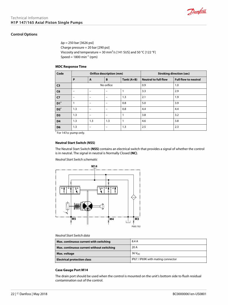
MDC Response Time
Code Orifice description (mm) Stroking direction (sec)
P A B Tank (A+B) Neutral to full flow Full flow to neutral
C3 No orifice 0.9 1.0
C6 – – – 1 3.3 2.9
C7 – – – 1.3 2.1 1.9
D1* 1 – – 0.8 5.0 3.9
D2* 1.3 – – 0.8 4.4 4.4
D3 1.3 – – 1 3.8 3.2
D4 1.3 1.3 1.3 1 4.6 3.8
D6 1.3 – – 1.3 2.5 2.3
* For 147cc pump only.
Neutral Start Switch (NSS)
The Neutral Start Switch (NSS) contains an electrical switch that provides a signal of whether the controlis in neutral. The signal in neutral is Normally Closed (NC).
Neutral Start Switch schematic
P005 702
M14
M5 M4 M3
Neutral Start Switch data
Max. continuous current with switching 8.4 A
Max. continuous current without switching 20 A
Max. voltage 36 VDC
Electrical protection class IP67 / IP69K with mating connector
Case Gauge Port M14
The drain port should be used when the control is mounted on the unit’s bottom side to flush residualcontamination out of the control.
Technical InformationH1P 147/165 Axial Piston Single Pumps
Control Options
22 | © Danfoss | May 2018 BC00000061en-US0801
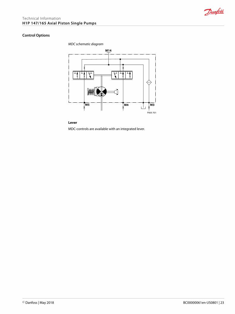
MDC schematic diagram
P005 701
M14
M5 M4 M3
Lever
MDC-controls are available with an integrated lever.
Technical InformationH1P 147/165 Axial Piston Single Pumps
Control Options
© Danfoss | May 2018 BC00000061en-US0801 | 23
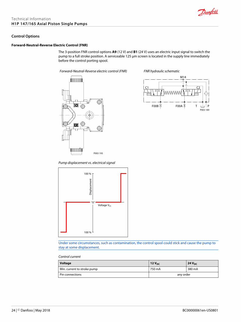
Forward-Neutral-Reverse Electric Control (FNR)
The 3-position FNR control options A9 (12 V) and B1 (24 V) uses an electric input signal to switch thepump to a full stroke position. A serviceable 125 μm screen is located in the supply line immediatelybefore the control porting spool.
Forward-Neutral-Reverse electric control (FNR)
P003 193
FNR hydraulic schematic
P003 189
C2C1
F00A
M14
T PF00B
Pump displacement vs. electrical signal
100 %
“0“
100 %
Voltage VDC
Dis
plac
emen
t
Under some circumstances, such as contamination, the control spool could stick and cause the pump tostay at some displacement.
Control current
Voltage 12 VDC 24 VDC
Min. current to stroke pump 750 mA 380 mA
Pin connections any order
Technical InformationH1P 147/165 Axial Piston Single Pumps
Control Options
24 | © Danfoss | May 2018 BC00000061en-US0801
Connector
1 2
P003 480
Connector ordering data
Description Quantity Ordering data
Mating connector 1 DEUTSCH DT06-2S
Wedge lock 1 DEUTSCH W2S
Socket contact (16 and 18 AWG) 2 DEUTSCH 0462-201-16141
Danfoss mating connector kit 1 K29657
Solenoid data
Voltage 12 VDC 24 VDC
Minimum supply voltage 9.5 VDC 19 VDC
Maximum supply voltage (continuous) 14.6 VDC 29 VDC
Bi-directional diode cut off voltage 28 VDC 53 VDC
Maximum current 1050 mA 500 mA
Nominal coil resistance @ 20°C 8.4 Ω 34.5 Ω
PWM Range 70-200 Hz
PWM Frequency (preferred)* 100 Hz
IP Rating (IEC 60 529) + DIN 40 050 IP 67/IP 69K (part 9 with mating connector)
* PWM signal required for optimum control performance.
Pump output flow direction vs. control signal
Shaft rotation CW CCW
Coil energized* C1 C2 C1 C2
Port A in out out in
Port B out in in out
Servo port pressurized M5 M4 M5 M4* For coil location see Installation drawings on page 53.
Control Response
H1 controls are available with optional control passage orifices to assist in matching the rate of swash-plate response to the application requirements. The time required for the pump output flow to changefrom zero to full flow (acceleration) or full flow to zero (deceleration) is a net function of spool porting,orifices, and charge pressure.
H1 pumps are limited in mechanical orifice combinations. Mechanical servo orifices are to be used onlyfor fail-safe return to neutral in a case of an electrical failure.
A swash-plate response times table is available for each frame size. Testing should be conducted to verifythe proper orifice selection for the desired response. Typical response times at the following conditions:
∆p = 250 bar [3626 psi]Charge pressure = 20 bar [290 psi]
Technical InformationH1P 147/165 Axial Piston Single Pumps
Control Options
© Danfoss | May 2018 BC00000061en-US0801 | 25
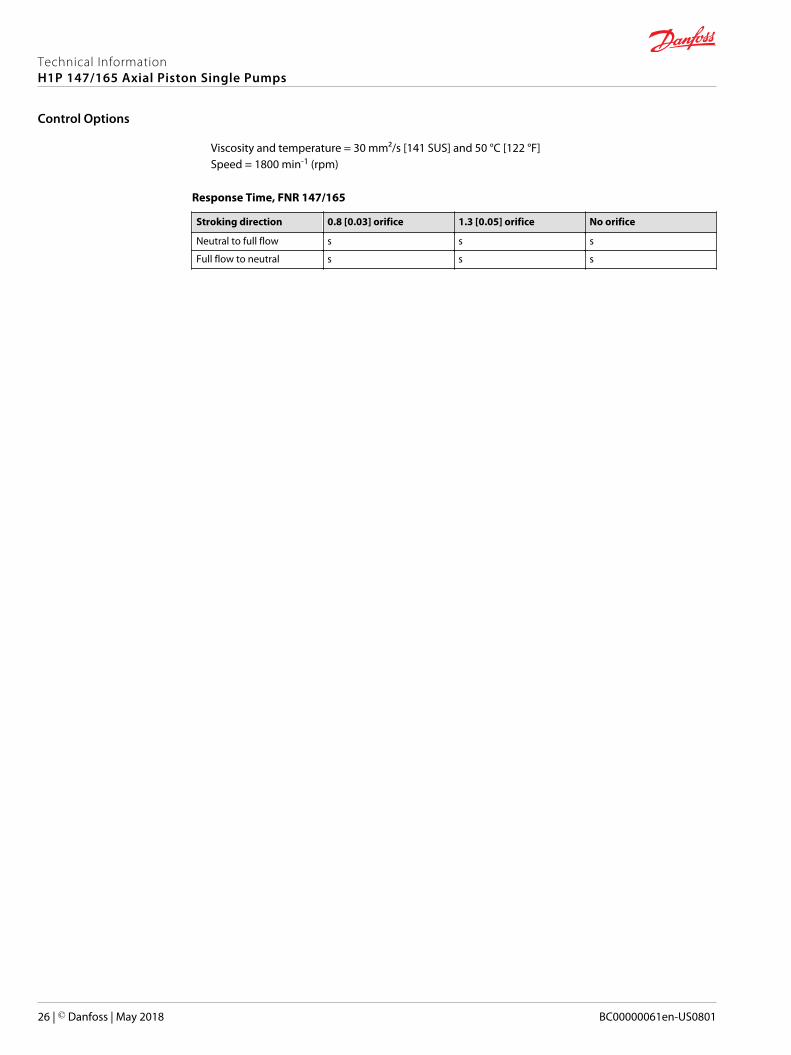
Viscosity and temperature = 30 mm²/s [141 SUS] and 50 °C [122 °F]Speed = 1800 min-1 (rpm)
Response Time, FNR 147/165
Stroking direction 0.8 [0.03] orifice 1.3 [0.05] orifice No orifice
Neutral to full flow s s s
Full flow to neutral s s s
Technical InformationH1P 147/165 Axial Piston Single Pumps
Control Options
26 | © Danfoss | May 2018 BC00000061en-US0801
Non Feedback Proportional Electric Control (NFPE)
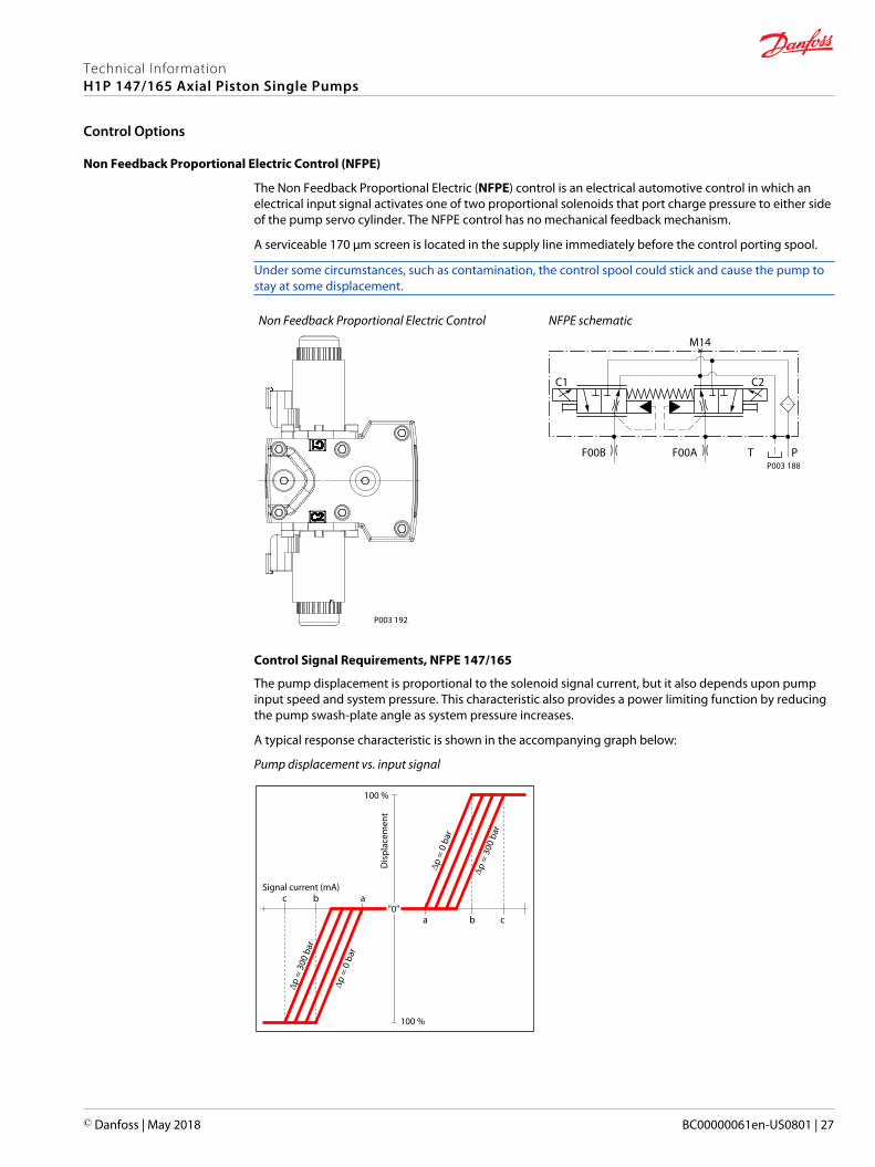
The Non Feedback Proportional Electric (NFPE) control is an electrical automotive control in which anelectrical input signal activates one of two proportional solenoids that port charge pressure to either sideof the pump servo cylinder. The NFPE control has no mechanical feedback mechanism.
A serviceable 170 μm screen is located in the supply line immediately before the control porting spool.
Under some circumstances, such as contamination, the control spool could stick and cause the pump tostay at some displacement.
Non Feedback Proportional Electric Control
P003 192
NFPE schematic
P003 188
C2C1
F00A
M14
T PF00B
Control Signal Requirements, NFPE 147/165
The pump displacement is proportional to the solenoid signal current, but it also depends upon pumpinput speed and system pressure. This characteristic also provides a power limiting function by reducingthe pump swash-plate angle as system pressure increases.
A typical response characteristic is shown in the accompanying graph below:
Pump displacement vs. input signal
"0"
Signal current (mA)
a b c
abc
Dis
plac
emen
t
100 %
100 %
p =
300
bar
p =
300
bar
p =
0 ba
r
p =
0 ba
r
Technical InformationH1P 147/165 Axial Piston Single Pumps
Control Options
© Danfoss | May 2018 BC00000061en-US0801 | 27
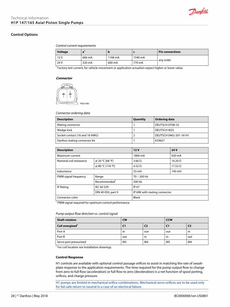
Control current requirements
Voltage a* b c Pin connections
12 V 666 mA 1168 mA 1540 mAany order
24 V 320 mA 600 mA 770 mA* Factory test current, for vehicle movement or application actuation expect higher or lower value.
Connector
1 2
P003 480
Connector ordering data
Description Quantity Ordering data
Mating connector 1 DEUTSCH DT06-2S
Wedge lock 1 DEUTSCH W2S
Socket contact (16 and 18 AWG) 2 DEUTSCH 0462-201-16141
Danfoss mating connector kit 1 K29657
Description 12 V 24 V
Maximum current 1800 mA 920 mA
Nominal coil resistance @ 20 °C [68 °F] 3.66 Ω 14.20 Ω
@ 80 °C [176 °F] 4.52 Ω 17.52 Ω
Inductance 33 mH 140 mH
PWM signal frequency Range 70 – 200 Hz
Recommended* 200 Hz
IP Rating IEC 60 529 IP 67
DIN 40 050, part 9 IP 69K with mating connector
Connector color Black* PWM signal required for optimum control performance.
Pump output flow direction vs. control signal
Shaft rotation CW CCW
Coil energized* C1 C2 C1 C2
Port A in out out in
Port B out in in out
Servo port pressurized M5 M4 M5 M4* For coil location see Installation drawings.
Control Response
H1 controls are available with optional control passage orifices to assist in matching the rate of swash-plate response to the application requirements. The time required for the pump output flow to changefrom zero to full flow (acceleration) or full flow to zero (deceleration) is a net function of spool porting,orifices, and charge pressure.
H1 pumps are limited in mechanical orifice combinations. Mechanical servo orifices are to be used onlyfor fail-safe return to neutral in a case of an electrical failure.
Technical InformationH1P 147/165 Axial Piston Single Pumps
Control Options
28 | © Danfoss | May 2018 BC00000061en-US0801
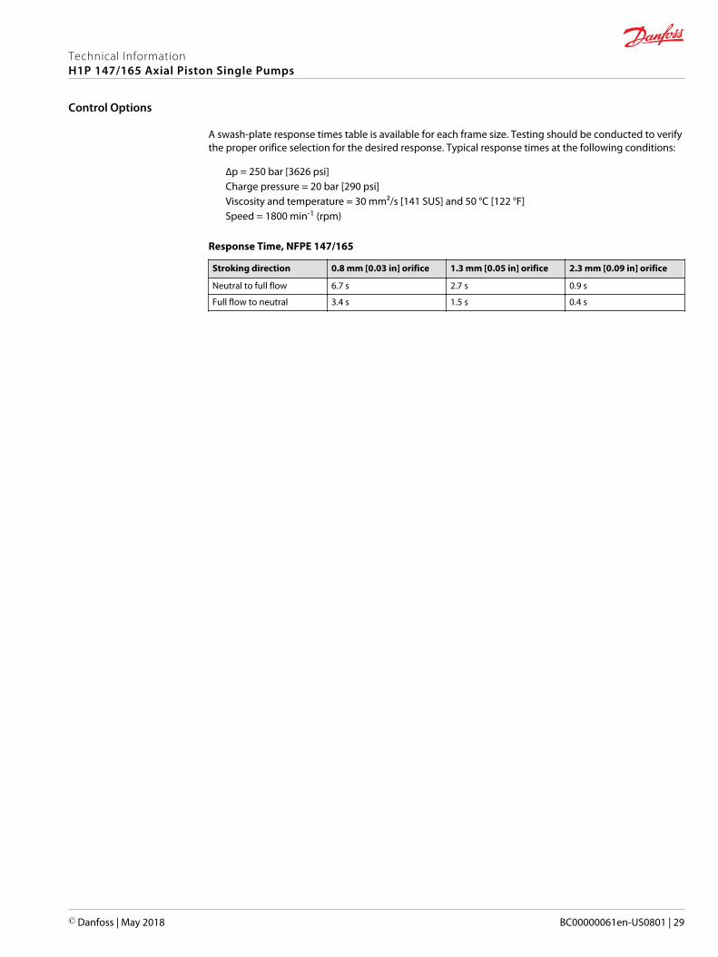
A swash-plate response times table is available for each frame size. Testing should be conducted to verifythe proper orifice selection for the desired response. Typical response times at the following conditions:
∆p = 250 bar [3626 psi]Charge pressure = 20 bar [290 psi]Viscosity and temperature = 30 mm²/s [141 SUS] and 50 °C [122 °F]Speed = 1800 min-1 (rpm)
Response Time, NFPE 147/165
Stroking direction 0.8 mm [0.03 in] orifice 1.3 mm [0.05 in] orifice 2.3 mm [0.09 in] orifice
Neutral to full flow 6.7 s 2.7 s 0.9 s
Full flow to neutral 3.4 s 1.5 s 0.4 s
Technical InformationH1P 147/165 Axial Piston Single Pumps
Control Options
© Danfoss | May 2018 BC00000061en-US0801 | 29
Automotive Control (AC)
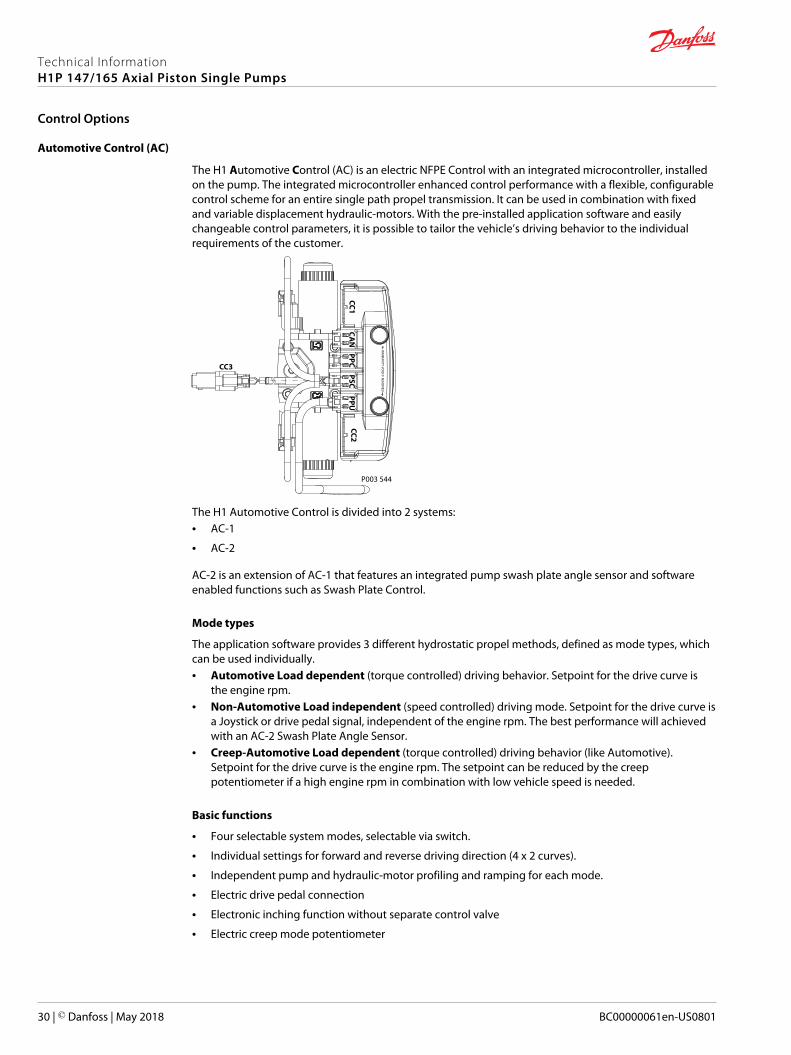
The H1 Automotive Control (AC) is an electric NFPE Control with an integrated microcontroller, installedon the pump. The integrated microcontroller enhanced control performance with a flexible, configurablecontrol scheme for an entire single path propel transmission. It can be used in combination with fixedand variable displacement hydraulic-motors. With the pre-installed application software and easilychangeable control parameters, it is possible to tailor the vehicle’s driving behavior to the individualrequirements of the customer.
P003 544
CAN
PPCPSC
PPUCC2
CC1
WA
RRAN
TY VOID
IF REMO
VED
CC3
The H1 Automotive Control is divided into 2 systems:• AC-1
• AC-2
AC-2 is an extension of AC-1 that features an integrated pump swash plate angle sensor and softwareenabled functions such as Swash Plate Control.
Mode types
The application software provides 3 different hydrostatic propel methods, defined as mode types, whichcan be used individually.• Automotive Load dependent (torque controlled) driving behavior. Setpoint for the drive curve is
the engine rpm.• Non-Automotive Load independent (speed controlled) driving mode. Setpoint for the drive curve is
a Joystick or drive pedal signal, independent of the engine rpm. The best performance will achievedwith an AC-2 Swash Plate Angle Sensor.
• Creep-Automotive Load dependent (torque controlled) driving behavior (like Automotive).Setpoint for the drive curve is the engine rpm. The setpoint can be reduced by the creeppotentiometer if a high engine rpm in combination with low vehicle speed is needed.
Basic functions
• Four selectable system modes, selectable via switch.
• Individual settings for forward and reverse driving direction (4 x 2 curves).
• Independent pump and hydraulic-motor profiling and ramping for each mode.
• Electric drive pedal connection
• Electronic inching function without separate control valve
• Electric creep mode potentiometer
Technical InformationH1P 147/165 Axial Piston Single Pumps
Control Options
30 | © Danfoss | May 2018 BC00000061en-US0801
• Configurable System Mode & Direction change
• Load independent pump displacement control with integrated Swash Plate Angle Sensor (AC-2)
• Hydraulic-motor displacement control including brake pressure defeat function
Performance functions
• ECO fuel saving mode with automatic reduction of the engine speed during transport (Cruise control)
• Vehicle constant speed drive control
• Vehicle speed limitation
• Dynamic brake light, automatic park brake, reverse buzzer and status LED outputs
• Vehicle speed controlled output function.
• Temperature compensation for predictable performance
• Advanced CAN J1939 interface for the information exchange with the vehicle control system
Protection and safety functions
• Safety controlled vehicle start protection with engine speed check, battery check and FNR must be inneutral, etc..
• Operator presence detection
• Hydraulic system overheat and low-temperature protection
• Hydraulic motor over speed protection
• Park brake test mode for roller applications to fulfill SAE J1472 / EN500-4.
• SIL2 compliant
Engine control and protection
• CAN J1939 engine interface
• Engine speed control via drive pedal with safety controlled monitoring function
• Engine antistall protection
• Engine over speed protection during inching
• Engine speed dependent Retarder control
• Engine cold start protection
Installation features
• Factory calibration for hysteresis compensation.
• Starting current adjustment in the factory
• Pre-installed application software and parameter files
For more information, see Automotive Control for H1 Single Pumps Technical Information, BC00000213.
Technical InformationH1P 147/165 Axial Piston Single Pumps
Control Options
© Danfoss | May 2018 BC00000061en-US0801 | 31
Fan Drive Control (FDC)
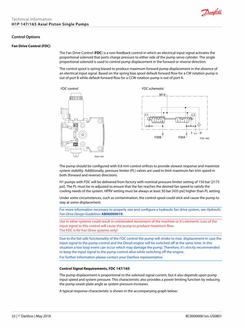
The Fan Drive Control (FDC) is a non-feedback control in which an electrical input signal activates theproportional solenoid that ports charge pressure to either side of the pump servo cylinder. The singleproportional solenoid is used to control pump displacement in the forward or reverse direction.
The control spool is spring biased to produce maximum forward pump displacement in the absence ofan electrical input signal. Based on the spring bias spool default forward flow for a CW rotation pump isout of port B while default forward flow for a CCW rotation pump is out of port A.
FDC control
P301 441
FDC schematic
PTF00B
M14
C1 C2
F00A P301 442
The pump should be configured with 0.8 mm control orifices to provide slowest response and maximizesystem stability. Additionally, pressure limiter (PL) valves are used to limit maximum fan trim speed inboth (forward and reverse) directions.
H1 pumps with FDC will be delivered from factory with nominal pressure limiter setting of 150 bar [2175psi]. The PL must be re-adjusted to ensure that the fan reaches the desired fan speed to satisfy thecooling needs of the system. HPRV setting must be always at least 30 bar [435 psi] higher than PL setting.
Under some circumstances, such as contamination, the control spool could stick and cause the pump tostay at some displacement.
For more information necessary to properly size and configure a hydraulic fan drive system, see HydraulicFan Drive Design Guidelines AB00000019.
Use in other systems could result in unintended movement of the machine or it’s elements. Loss of theinput signal to this control will cause the pump to produce maximum flow.The FDC is for Fan Drive systems only!
Due to the fail-safe functionality of the FDC control the pump will stroke to max. displacement in case theinput signal to the pump control and the Diesel engine will be switched off at the same time. In thissituation a low loop event can occur which may damage the pump. Therefore, it’s strictly recommendedto keep the input signal to the pump control alive while switching off the engine.For further information please contact your Danfoss representative.
Control Signal Requirements, FDC 147/165
The pump displacement is proportional to the solenoid signal current, but it also depends upon pumpinput speed and system pressure. This characteristic also provides a power limiting function by reducingthe pump swash plate angle as system pressure increases.
A typical response characteristic is shown in the accompanying graph below:
Technical InformationH1P 147/165 Axial Piston Single Pumps
Control Options
32 | © Danfoss | May 2018 BC00000061en-US0801
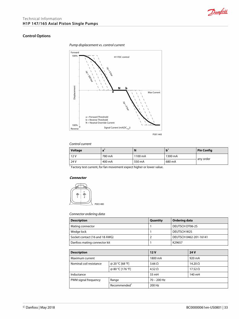
Pump displacement vs. control current
100%
100%
Dis
plac
emen
t
0 Signal Current (mA(DCAvg))
Max Current
H1 FDC control
Na
b
a = Forward Thresholdb = Reverse ThresholdN = Neutral Override Current
P301 443∆p = 0 bar
∆p = 0 bar
∆p = 300 bar
Reverse
Forward
Control current
Voltage a* N b* Pin Config
12 V 780 mA 1100 mA 1300 mAany order
24 V 400 mA 550 mA 680 mA* Factory test current, for fan movement expect higher or lower value.
Connector
1 2
P003 480
Connector ordering data
Description Quantity Ordering data
Mating connector 1 DEUTSCH DT06-2S
Wedge lock 1 DEUTSCH W2S
Socket contact (16 and 18 AWG) 2 DEUTSCH 0462-201-16141
Danfoss mating connector kit 1 K29657
Description 12 V 24 V
Maximum current 1800 mA 920 mA
Nominal coil resistance @ 20 °C [68 °F] 3.66 Ω 14.20 Ω
@ 80 °C [176 °F] 4.52 Ω 17.52 Ω
Inductance 33 mH 140 mH
PWM signal frequency Range 70 – 200 Hz
Recommended* 200 Hz
Technical InformationH1P 147/165 Axial Piston Single Pumps
Control Options
© Danfoss | May 2018 BC00000061en-US0801 | 33
Description 12 V 24 V
IP Rating IEC 60 529 IP 67
DIN 40 050, part 9 IP 69K with mating connector
Connector color Black* PWM signal required for optimum control performance.
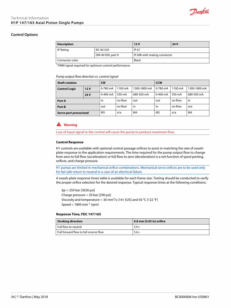
Pump output flow direction vs. control signal
Shaft rotation CW CCW
Control Logic 12 V 0-780 mA 1100 mA 1300-1800 mA 0-780 mA 1100 mA 1300-1800 mA
24 V 0-400 mA 550 mA 680-920 mA 0-400 mA 550 mA 680-920 mA
Port A in no flow out out no flow in
Port B out no flow in in no flow out
Servo port pressurized M5 n/a M4 M5 n/a M4
W Warning
Loss of input signal to the control will cause the pump to produce maximum flow.
Control Response
H1 controls are available with optional control passage orifices to assist in matching the rate of swash-plate response to the application requirements. The time required for the pump output flow to changefrom zero to full flow (acceleration) or full flow to zero (deceleration) is a net function of spool porting,orifices, and charge pressure.
H1 pumps are limited in mechanical orifice combinations. Mechanical servo orifices are to be used onlyfor fail-safe return to neutral in a case of an electrical failure.
A swash-plate response times table is available for each frame size. Testing should be conducted to verifythe proper orifice selection for the desired response. Typical response times at the following conditions:
∆p = 250 bar [3626 psi]Charge pressure = 20 bar [290 psi]Viscosity and temperature = 30 mm²/s [141 SUS] and 50 °C [122 °F]Speed = 1800 min-1 (rpm)
Response Time, FDC 147/165
Stroking direction 0.8 mm [0.03 in] orifice
Full flow to neutral 3.9 s
Full forward flow to full reverse flow 5.6 s
Technical InformationH1P 147/165 Axial Piston Single Pumps
Control Options
34 | © Danfoss | May 2018 BC00000061en-US0801
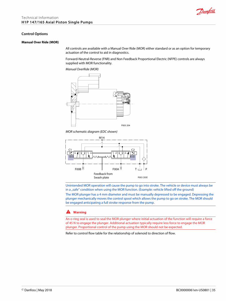
Manual Over Ride (MOR)
All controls are available with a Manual Over Ride (MOR) either standard or as an option for temporaryactuation of the control to aid in diagnostics.
Forward-Neutral-Reverse (FNR) and Non Feedback Proportional Electric (NFPE) controls are alwayssupplied with MOR functionality.
Manual OverRide (MOR)
P003 204
MOR schematic diagram (EDC shown)
Feedback from Swash plate
PTF00B
M14
C2C1
F00A
P003 205E
Unintended MOR operation will cause the pump to go into stroke. The vehicle or device must always bein a „safe“ condition when using the MOR function. (Example: vehicle lifted off the ground)The MOR plunger has a 4 mm diameter and must be manually depressed to be engaged. Depressing theplunger mechanically moves the control spool which allows the pump to go on stroke. The MOR shouldbe engaged anticipating a full stroke response from the pump.
W Warning
An o-ring seal is used to seal the MOR plunger where initial actuation of the function will require a forceof 45 N to engage the plunger. Additional actuation typically require less force to engage the MORplunger. Proportional control of the pump using the MOR should not be expected.
Refer to control flow table for the relationship of solenoid to direction of flow.
Technical InformationH1P 147/165 Axial Piston Single Pumps
Control Options
© Danfoss | May 2018 BC00000061en-US0801 | 35
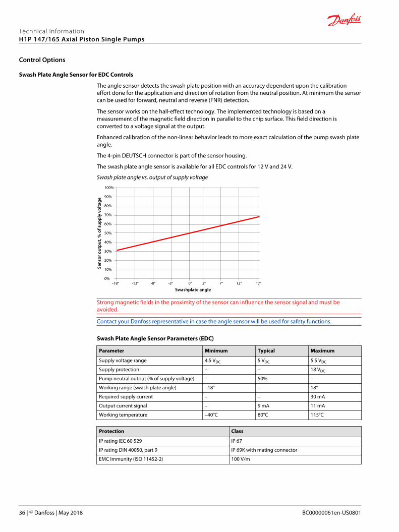
Swash Plate Angle Sensor for EDC Controls
The angle sensor detects the swash plate position with an accuracy dependent upon the calibrationeffort done for the application and direction of rotation from the neutral position. At minimum the sensorcan be used for forward, neutral and reverse (FNR) detection.
The sensor works on the hall-effect technology. The implemented technology is based on ameasurement of the magnetic field direction in parallel to the chip surface. This field direction isconverted to a voltage signal at the output.
Enhanced calibration of the non-linear behavior leads to more exact calculation of the pump swash plateangle.
The 4-pin DEUTSCH connector is part of the sensor housing.
The swash plate angle sensor is available for all EDC controls for 12 V and 24 V.
Swash plate angle vs. output of supply voltage
-18° -13° -8°
100%
90%
80%
70%
60%
50%
40%
30%
20%
10%
0%
Swashplate angle
Sens
or o
utpu
t, %
of s
uppl
y vo
ltage
-3° 0° 2° 7° 12° 17°
Strong magnetic fields in the proximity of the sensor can influence the sensor signal and must beavoided.
Contact your Danfoss representative in case the angle sensor will be used for safety functions.
Swash Plate Angle Sensor Parameters (EDC)
Parameter Minimum Typical Maximum
Supply voltage range 4.5 VDC 5 VDC 5.5 VDC
Supply protection – – 18 VDC
Pump neutral output (% of supply voltage) – 50% –
Working range (swash plate angle) –18° – 18°
Required supply current – – 30 mA
Output current signal – 9 mA 11 mA
Working temperature –40°C 80°C 115°C
Protection Class
IP rating IEC 60 529 IP 67
IP rating DIN 40050, part 9 IP 69K with mating connector
EMC Immunity (ISO 11452-2) 100 V/m
Technical InformationH1P 147/165 Axial Piston Single Pumps
Control Options
36 | © Danfoss | May 2018 BC00000061en-US0801
Calibration of the sensor output within the software is mandatory. Vehicle neutral thresholds in thesoftware (±0.5°) are vehicle dependent and must consider different conditions, example: systemtemperature, system pressure and/or shaft speed.
For safety function: If the sensor fails (invalid signal <10% or >90% of supply voltage), it must be surethat the ECU will go into a diagnostic mode and shift into limited mode in order for the driver to take thefull control or the mechanical breaks should be activated.
Strong magnetic fields in the proximity of the sensor can influence the sensor signal and must beavoided.
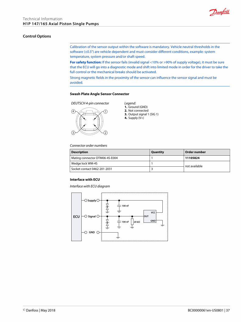
Swash Plate Angle Sensor Connector
DEUTSCH 4-pin connector
1
23
4
Legend:1. Ground (GND)2. Not connected3. Output signal 1 (SIG 1)4. Supply (V+)
Connector order numbers
Description Quantity Order number
Mating connector DTM06-4S-E004 1 11105824
Wedge lock WM-4S 1not available
Socket contact 0462-201-2031 3
Interface with ECU
Interface with ECU diagram
ECU
Supply
Signal
GND
GND
OUT
VCC
100 nF 20 kΩ
100 nF
Technical InformationH1P 147/165 Axial Piston Single Pumps
Control Options
© Danfoss | May 2018 BC00000061en-US0801 | 37
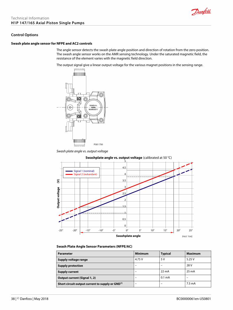
Swash plate angle sensor for NFPE and AC2 controls
The angle sensor detects the swash plate angle position and direction of rotation from the zero position.The swash angle sensor works on the AMR sensing technology. Under the saturated magnetic field, theresistance of the element varies with the magnetic field direction.
The output signal give a linear output voltage for the various magnet positions in the sensing range.
P301 750
Swash plate angle vs. output voltage
-25° -20° -15° -10° -5° 0° 5° 10° 15° 20° 25°
5
4.5
4
3.5
3
2.5
2
1.5
1
0.5
0
Swashplate angle
Out
put v
olta
ge
(V
)
P005 704E
Signal 1 (nominal)Signal 2 (redundant)
Swashplate angle vs. output voltage (calibrated at 50 °C)
Swash Plate Angle Sensor Parameters (NFPE/AC)
Parameter Minimum Typical Maximum
Supply voltage range 4.75 V 5 V 5.25 V
Supply protection – – 28 V
Supply current – 22 mA 25 mA
Output current (Signal 1, 2) – 0.1 mA –
Short circuit output current to supply or GND1) – – 7.5 mA
Technical InformationH1P 147/165 Axial Piston Single Pumps
Control Options
38 | © Danfoss | May 2018 BC00000061en-US0801
Parameter Minimum Typical Maximum
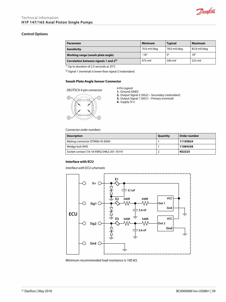
Sensitivity 70.0 mV/deg 78.0 mV/deg 85.8 mV/deg
Working range (swash plate angle) –18° 0° 18°
Correlation between signals 1 and 22) 475 mV 500 mV 525 mV
1) Up to duration of 2.5 seconds at 25°C2) Signal 1 (nominal) is lower than signal 2 (redundant)
Swash Plate Angle Sensor Connector
DEUTSCH 4-pin connector
1
23
4
4-Pin Legend:1. Ground (GND)2. Output Signal 2 (SIG2) – Secondary (redundant)3. Output Signal 1 (SIG1) – Primary (nominal)4. Supply (V+)
Connector order numbers
Description Quantity Order number
Mating connector DTM06-4S-E004 1 11105824
Wedge lock W4S 1 11084558
Socket contact (16-18 AWG) 0462-201-16141 2 K02325
Interface with ECU
Interface with ECU schematic
ECU
V+
Sig1
Sig2
Gnd
E3 340R 340ROut 2
Out 1
VCC
VCC
Gnd
Gnd
340R340R
0.1uF
5.6 nF
5.6 nF
E2
E1
Minimum recommended load resistance is 100 kΩ.
Technical InformationH1P 147/165 Axial Piston Single Pumps
Control Options
© Danfoss | May 2018 BC00000061en-US0801 | 39
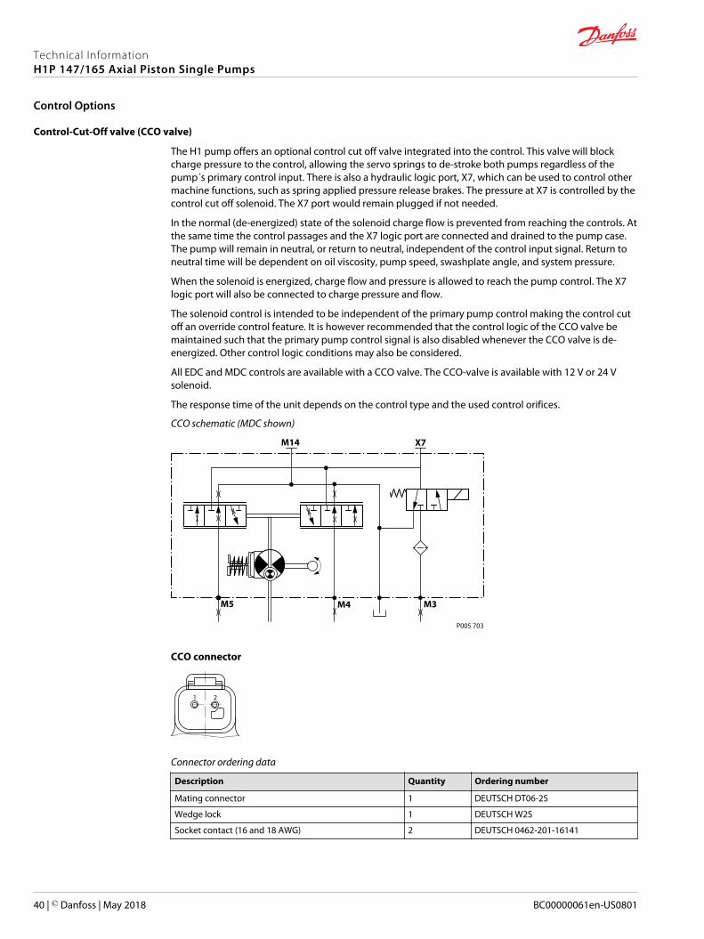
Control-Cut-Off valve (CCO valve)
The H1 pump offers an optional control cut off valve integrated into the control. This valve will blockcharge pressure to the control, allowing the servo springs to de-stroke both pumps regardless of thepump´s primary control input. There is also a hydraulic logic port, X7, which can be used to control othermachine functions, such as spring applied pressure release brakes. The pressure at X7 is controlled by thecontrol cut off solenoid. The X7 port would remain plugged if not needed.
In the normal (de-energized) state of the solenoid charge flow is prevented from reaching the controls. Atthe same time the control passages and the X7 logic port are connected and drained to the pump case.The pump will remain in neutral, or return to neutral, independent of the control input signal. Return toneutral time will be dependent on oil viscosity, pump speed, swashplate angle, and system pressure.
When the solenoid is energized, charge flow and pressure is allowed to reach the pump control. The X7logic port will also be connected to charge pressure and flow.
The solenoid control is intended to be independent of the primary pump control making the control cutoff an override control feature. It is however recommended that the control logic of the CCO valve bemaintained such that the primary pump control signal is also disabled whenever the CCO valve is de-energized. Other control logic conditions may also be considered.
All EDC and MDC controls are available with a CCO valve. The CCO-valve is available with 12 V or 24 Vsolenoid.
The response time of the unit depends on the control type and the used control orifices.
CCO schematic (MDC shown)
P005 703
M14
M5 M4 M3
X7
CCO connector
1 2
Connector ordering data
Description Quantity Ordering number
Mating connector 1 DEUTSCH DT06-2S
Wedge lock 1 DEUTSCH W2S
Socket contact (16 and 18 AWG) 2 DEUTSCH 0462-201-16141
Technical InformationH1P 147/165 Axial Piston Single Pumps
Control Options
40 | © Danfoss | May 2018 BC00000061en-US0801
CCO solenoid data
Nominal supply voltage 12 V 24 V
Supply voltage Maximum 14.6 V 29 V
Minimum 9.5 V 19 V
Nominal coil resistance at 20°C 10.7 Ω 41.7 Ω
Supply current Maximum 850 mA 430 mA
Minimum 580 mA 300 mA
PWM frequency Range 50-200 Hz 50-200 Hz
Preferred 100 Hz 100 Hz
Electrical protection class IP67 / IP69K with mating connector
Bi-directional diode cut off voltage 28 V 53 V
Brake gauge port with MDC
C Caution
It is not recommended to use brake port for any external flow consumption to avoid malfunction of CCOfunction.
Technical InformationH1P 147/165 Axial Piston Single Pumps
Control Options
© Danfoss | May 2018 BC00000061en-US0801 | 41
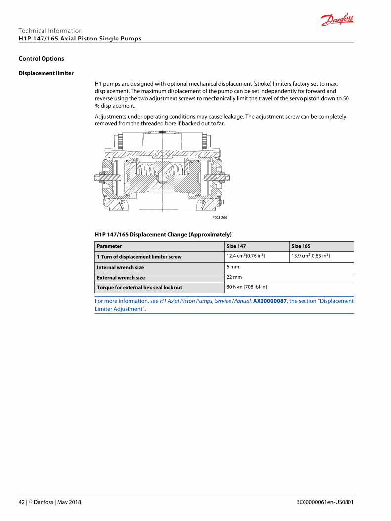
Displacement limiter
H1 pumps are designed with optional mechanical displacement (stroke) limiters factory set to max.displacement. The maximum displacement of the pump can be set independently for forward andreverse using the two adjustment screws to mechanically limit the travel of the servo piston down to 50% displacement.
Adjustments under operating conditions may cause leakage. The adjustment screw can be completelyremoved from the threaded bore if backed out to far.
P003 266
H1P 147/165 Displacement Change (Approximately)
Parameter Size 147 Size 165
1 Turn of displacement limiter screw 12.4 cm3[0.76 in3] 13.9 cm3[0.85 in3]
Internal wrench size 6 mm
External wrench size 22 mm
Torque for external hex seal lock nut 80 N•m [708 lbf•in]
For more information, see H1 Axial Piston Pumps, Service Manual, AX00000087, the section “DisplacementLimiter Adjustment”.
Technical InformationH1P 147/165 Axial Piston Single Pumps
Control Options
42 | © Danfoss | May 2018 BC00000061en-US0801
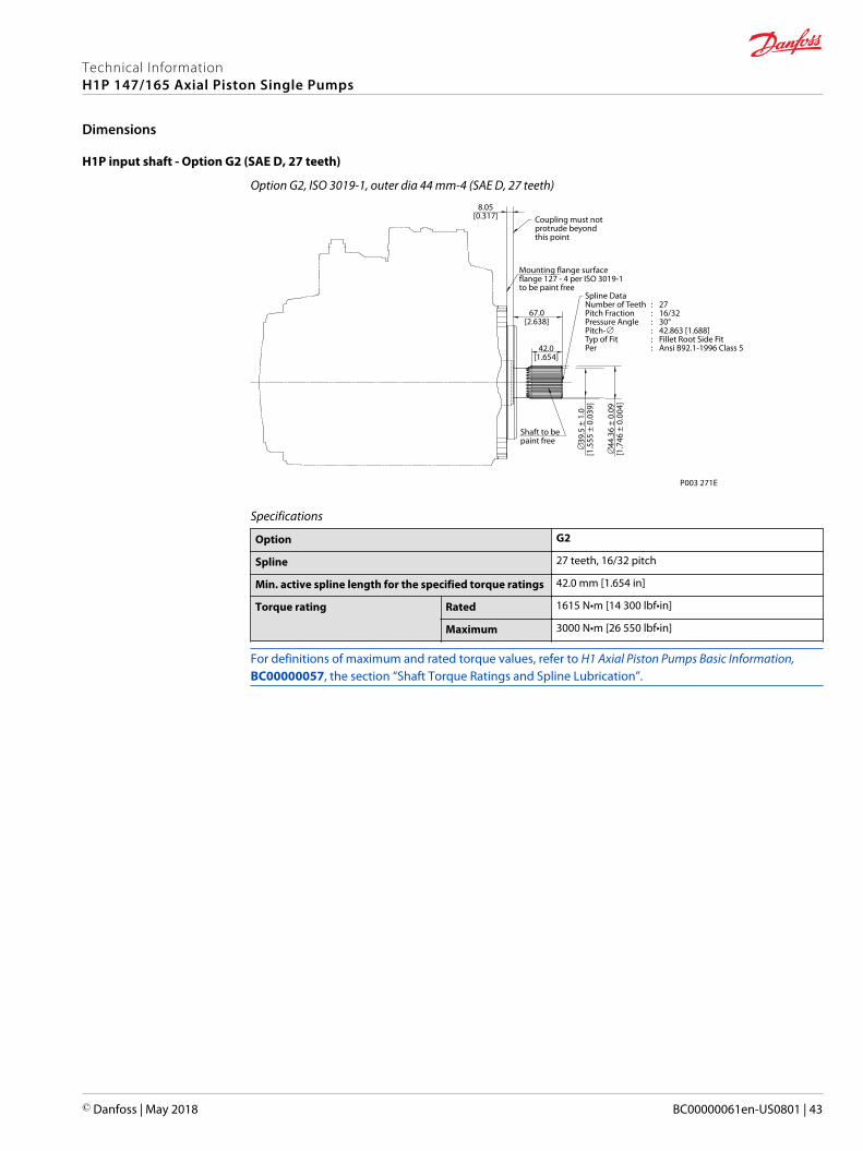
H1P input shaft - Option G2 (SAE D, 27 teeth)
Option G2, ISO 3019-1, outer dia 44 mm-4 (SAE D, 27 teeth)
P003 271E
∅39
.5 ±
1.0
[1.5
55 ±
0.0
39]
∅44
.36
± 0.
09[1
.746
± 0
.004
]
42.0[1.654]
67.0[2.638]
Coupling must notprotrude beyondthis point
Mounting flange surfaceflange 127 - 4 per ISO 3019-1to be paint free
8.05[0.317]
Spline Data Number of Teeth : 27Pitch Fraction : 16/32Pressure Angle : 30°Pitch-∅ : 42.863 [1.688]Typ of Fit : Fillet Root Side FitPer : Ansi B92.1-1996 Class 5
Shaft to be paint free
Specifications
Option G2
Spline 27 teeth, 16/32 pitch
Min. active spline length for the specified torque ratings 42.0 mm [1.654 in]
Torque rating Rated 1615 N•m [14 300 lbf•in]
Maximum 3000 N•m [26 550 lbf•in]
For definitions of maximum and rated torque values, refer to H1 Axial Piston Pumps Basic Information,BC00000057, the section “Shaft Torque Ratings and Spline Lubrication”.
Technical InformationH1P 147/165 Axial Piston Single Pumps
Dimensions
© Danfoss | May 2018 BC00000061en-US0801 | 43
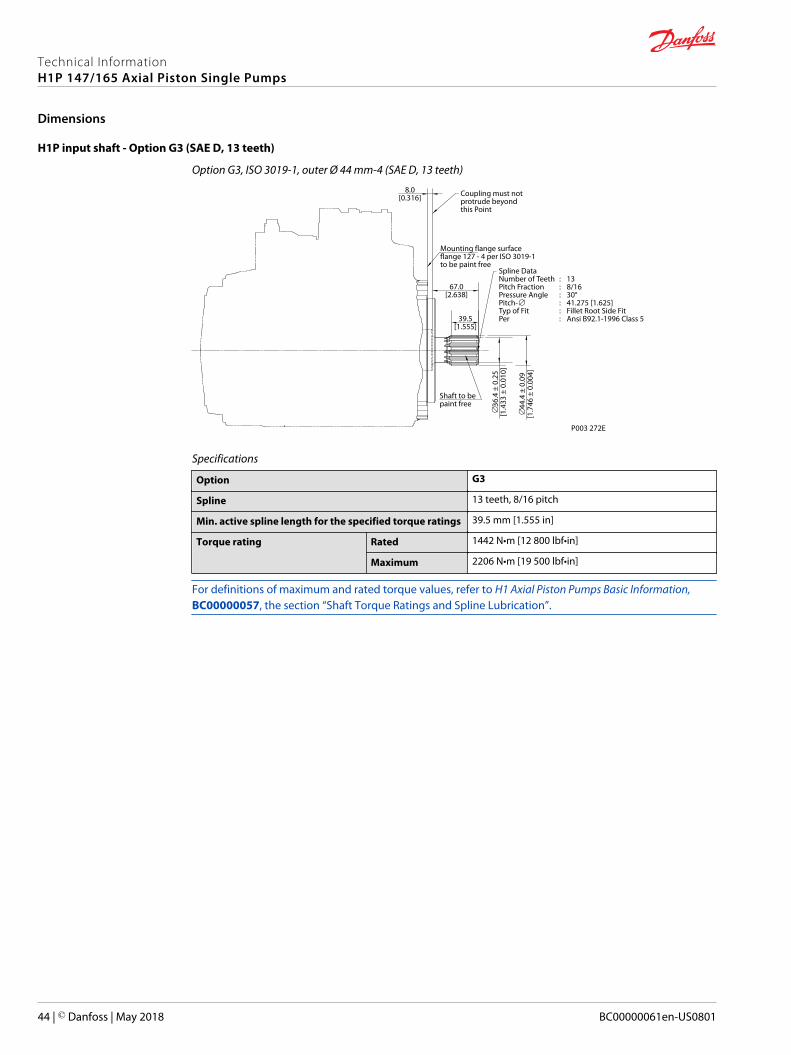
H1P input shaft - Option G3 (SAE D, 13 teeth)
Option G3, ISO 3019-1, outer Ø 44 mm-4 (SAE D, 13 teeth)
P003 272E
∅36
.4 ±
0.2
5[1
.433
± 0
.010
]
∅44
.4 ±
0.0
9[1
.746
± 0
.004
]
39.5[1.555]
67.0[2.638]
Coupling must notprotrude beyondthis Point
Spline Data Number of Teeth : 13Pitch Fraction : 8/16Pressure Angle : 30°Pitch-∅ : 41.275 [1.625]Typ of Fit : Fillet Root Side FitPer : Ansi B92.1-1996 Class 5
Mounting flange surfaceflange 127 - 4 per ISO 3019-1to be paint free
8.0[0.316]
Shaft to be paint free
Specifications
Option G3
Spline 13 teeth, 8/16 pitch
Min. active spline length for the specified torque ratings 39.5 mm [1.555 in]
Torque rating Rated 1442 N•m [12 800 lbf•in]
Maximum 2206 N•m [19 500 lbf•in]
For definitions of maximum and rated torque values, refer to H1 Axial Piston Pumps Basic Information,BC00000057, the section “Shaft Torque Ratings and Spline Lubrication”.
Technical InformationH1P 147/165 Axial Piston Single Pumps
Dimensions
44 | © Danfoss | May 2018 BC00000061en-US0801
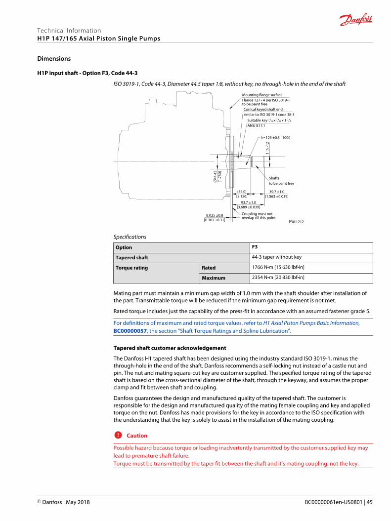
H1P input shaft - Option F3, Code 44-3
ISO 3019-1, Code 44-3, Diameter 44.5 taper 1:8, without key, no through-hole in the end of the shaft
P301 212
Coupling must notoverlap till this point
Conical keyed shaft endsimilar to ISO 3019-1 code 38-3
Suitable key 7/16 x 7/16 x 1 3/4
ANSI B17.1
125 ±0.5 : 1000
Shaftsto be paint free
8.025 ±0.8[0.361 ±0.31]
93.7 ±1.0[3.689 ±0.039]
1 1 / 4
-12
∅44
.45
[1.7
50]
39.7 ±1.0[1.563 ±0.039]
(54.0)[2.126]
Mounting flange surfaceFlange 127 - 4 per ISO 3019-1to be paint free
Specifications
Option F3
Tapered shaft 44-3 taper without key
Torque rating Rated 1766 N•m [15 630 lbf•in]
Maximum 2354 N•m [20 830 lbf•in]
Mating part must maintain a minimum gap width of 1.0 mm with the shaft shoulder after installation ofthe part. Transmittable torque will be reduced if the minimum gap requirement is not met.
Rated torque includes just the capability of the press-fit in accordance with an assumed fastener grade 5.
For definitions of maximum and rated torque values, refer to H1 Axial Piston Pumps Basic Information,BC00000057, the section “Shaft Torque Ratings and Spline Lubrication”.
Tapered shaft customer acknowledgement
The Danfoss H1 tapered shaft has been designed using the industry standard ISO 3019-1, minus thethrough-hole in the end of the shaft. Danfoss recommends a self-locking nut instead of a castle nut andpin. The nut and mating square-cut key are customer supplied. The specified torque rating of the taperedshaft is based on the cross-sectional diameter of the shaft, through the keyway, and assumes the properclamp and fit between shaft and coupling.
Danfoss guarantees the design and manufactured quality of the tapered shaft. The customer isresponsible for the design and manufactured quality of the mating female coupling and key and appliedtorque on the nut. Danfoss has made provisions for the key in accordance to the ISO specification withthe understanding that the key is solely to assist in the installation of the mating coupling.
C Caution
Possible hazard because torque or loading inadvertently transmitted by the customer supplied key maylead to premature shaft failure.Torque must be transmitted by the taper fit between the shaft and it’s mating coupling, not the key.
Technical InformationH1P 147/165 Axial Piston Single Pumps
Dimensions
© Danfoss | May 2018 BC00000061en-US0801 | 45
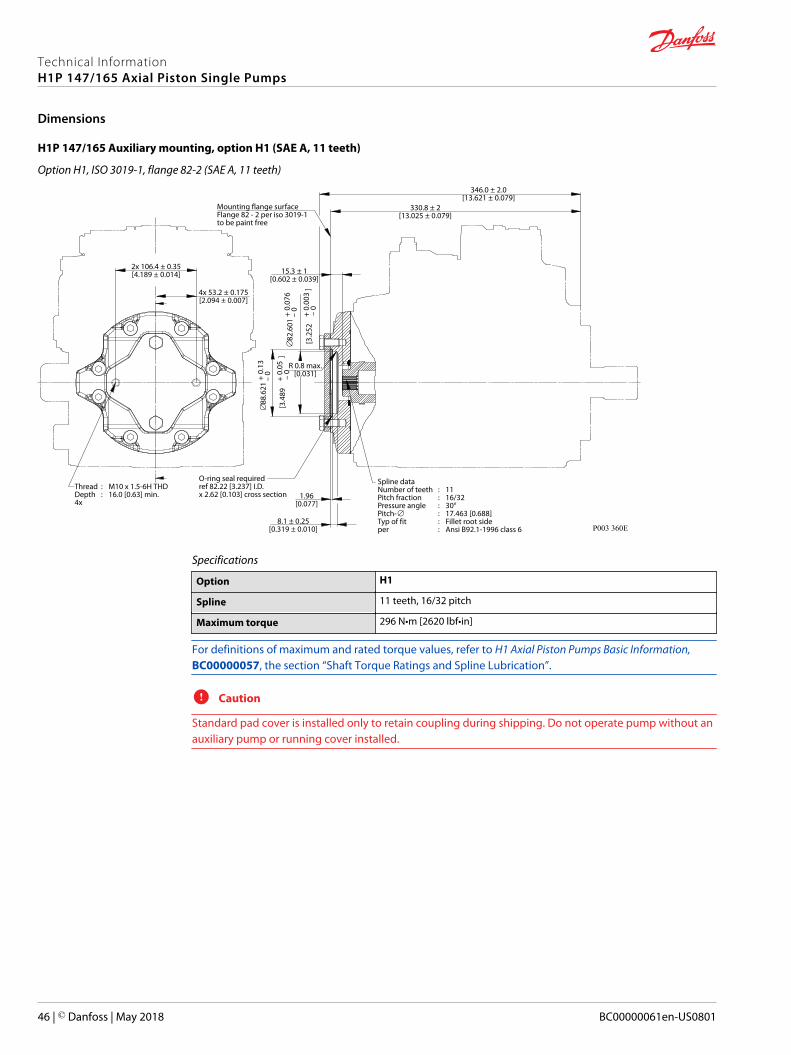
H1P 147/165 Auxiliary mounting, option H1 (SAE A, 11 teeth)
Option H1, ISO 3019-1, flange 82-2 (SAE A, 11 teeth)
P003 360E
2x 106.4 ± 0.35[4.189 ± 0.014]
8.1 ± 0.25[0.319 ± 0.010]
346.0 ± 2.0[13.621 ± 0.079]
330.8 ± 2[13.025 ± 0.079]
15.3 ± 1[0.602 ± 0.039]
4x 53.2 ± 0.175[2.094 ± 0.007]
∅88
.621
+ 0.
13
– 0
[3.4
89
+ 0.
05
–
0
]∅
82.6
01 +
0.07
6
–
0
[3.2
52
+ 0.
003
–
0
]
1.96[0.077]
R 0.8 max.[0.031]
Thread : M10 x 1.5-6H THDDepth : 16.0 [0.63] min.4x
Spline dataNumber of teeth : 11Pitch fraction : 16/32Pressure angle : 30°Pitch-∅ : 17.463 [0.688]Typ of fit : Fillet root sideper : Ansi B92.1-1996 class 6
O-ring seal requiredref 82.22 [3.237] I.D. x 2.62 [0.103] cross section
Mounting flange surfaceFlange 82 - 2 per iso 3019-1to be paint free
Specifications
Option H1
Spline 11 teeth, 16/32 pitch
Maximum torque 296 N•m [2620 lbf•in]
For definitions of maximum and rated torque values, refer to H1 Axial Piston Pumps Basic Information,BC00000057, the section “Shaft Torque Ratings and Spline Lubrication”.
C Caution
Standard pad cover is installed only to retain coupling during shipping. Do not operate pump without anauxiliary pump or running cover installed.
Technical InformationH1P 147/165 Axial Piston Single Pumps
Dimensions
46 | © Danfoss | May 2018 BC00000061en-US0801
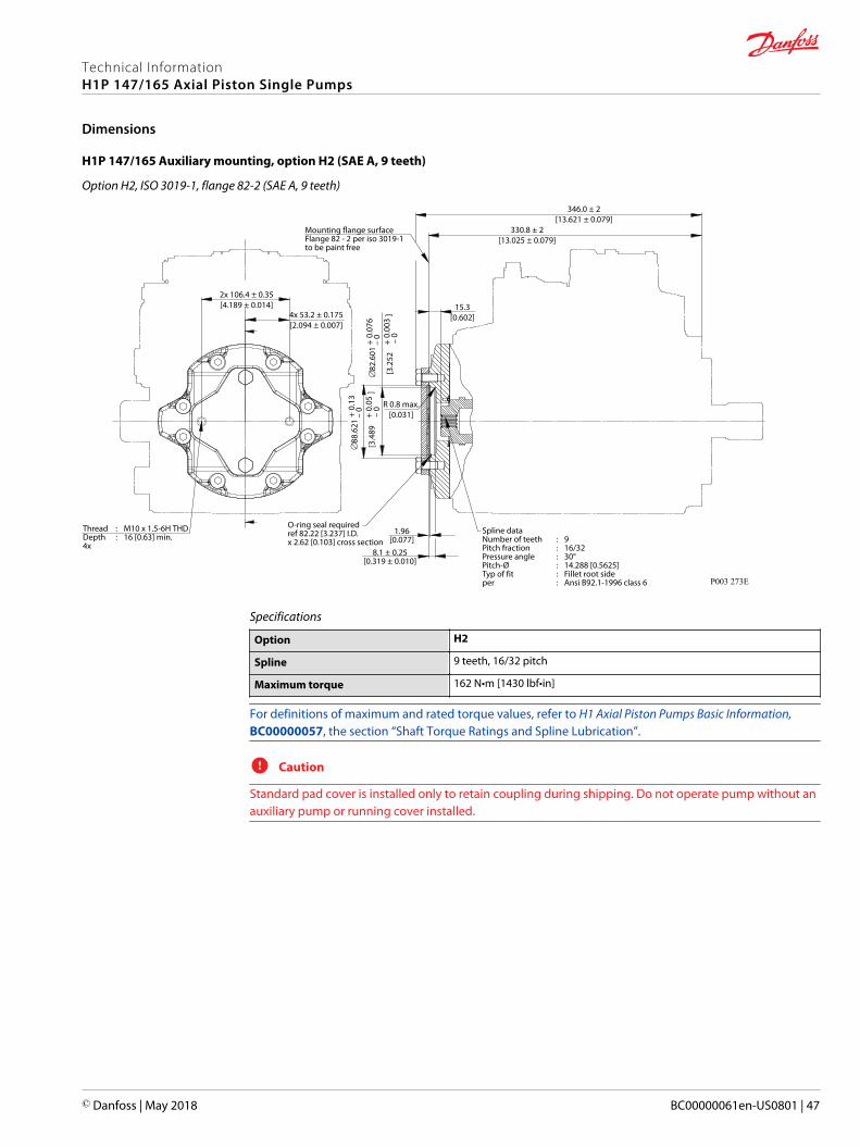
H1P 147/165 Auxiliary mounting, option H2 (SAE A, 9 teeth)
Option H2, ISO 3019-1, flange 82-2 (SAE A, 9 teeth)
P003 273E
2x 106.4 ± 0.35[4.189 ± 0.014]
8.1 ± 0.25[0.319 ± 0.010]
346.0 ± 2[13.621 ± 0.079]
330.8 ± 2[13.025 ± 0.079]
15.3[0.602]4x 53.2 ± 0.175
[2.094 ± 0.007]
∅88
.621
+ 0.
13
– 0
[3.4
89
+ 0.
05
– 0
]∅
82.6
01 +
0.07
6
–
0[3
.252
+
0.00
3
–
0
]
1.96[0.077]
Spline dataNumber of teeth : 9Pitch fraction : 16/32Pressure angle : 30°Pitch-Ø : 14.288 [0.5625]Typ of fit : Fillet root sideper : Ansi B92.1-1996 class 6
Thread : M10 x 1.5-6H THDDepth : 16 [0.63] min.4x
R 0.8 max.[0.031]
O-ring seal requiredref 82.22 [3.237] I.D. x 2.62 [0.103] cross section
Mounting flange surfaceFlange 82 - 2 per iso 3019-1to be paint free
Specifications
Option H2
Spline 9 teeth, 16/32 pitch
Maximum torque 162 N•m [1430 lbf•in]
For definitions of maximum and rated torque values, refer to H1 Axial Piston Pumps Basic Information,BC00000057, the section “Shaft Torque Ratings and Spline Lubrication”.
C Caution
Standard pad cover is installed only to retain coupling during shipping. Do not operate pump without anauxiliary pump or running cover installed.
Technical InformationH1P 147/165 Axial Piston Single Pumps
Dimensions
© Danfoss | May 2018 BC00000061en-US0801 | 47
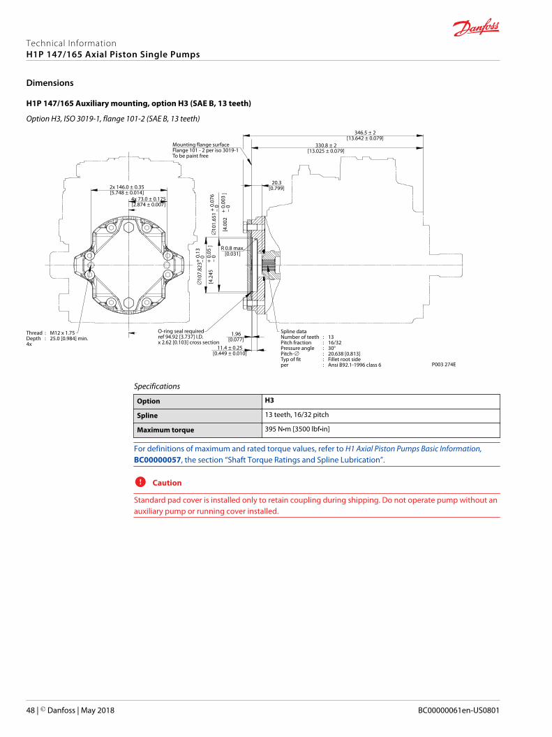
H1P 147/165 Auxiliary mounting, option H3 (SAE B, 13 teeth)
Option H3, ISO 3019-1, flange 101-2 (SAE B, 13 teeth)
2x 146.0 ± 0.35[5.748 ± 0.014]
11.4 ± 0.25[0.449 ± 0.010]
346.5 ± 2[13.642 ± 0.079]
330.8 ± 2[13.025 ± 0.079]
20.3[0.799]
4x 73.0 ± 0.175[2.874 ± 0.007]
∅10
7.82
3+ 0.
13
–
0[4
.245
+ 0.
05
–
0
]
∅10
1.65
1 +
0.07
6
–
0[4
.002
+
0.00
3
–
0
]
1.96[0.077]
R 0.8 max.[0.031]
P003 274E
Thread : M12 x 1.75Depth : 25.0 [0.984] min.4x
Spline dataNumber of teeth : 13Pitch fraction : 16/32Pressure angle : 30°Pitch-∅ : 20.638 [0.813]Typ of fit : Fillet root sideper : Ansi B92.1-1996 class 6
O-ring seal requiredref 94.92 [3.737] I.D. x 2.62 [0.103] cross section
Mounting flange surfaceFlange 101 - 2 per iso 3019-1To be paint free
Specifications
Option H3
Spline 13 teeth, 16/32 pitch
Maximum torque 395 N•m [3500 lbf•in]
For definitions of maximum and rated torque values, refer to H1 Axial Piston Pumps Basic Information,BC00000057, the section “Shaft Torque Ratings and Spline Lubrication”.
C Caution
Standard pad cover is installed only to retain coupling during shipping. Do not operate pump without anauxiliary pump or running cover installed.
Technical InformationH1P 147/165 Axial Piston Single Pumps
Dimensions
48 | © Danfoss | May 2018 BC00000061en-US0801
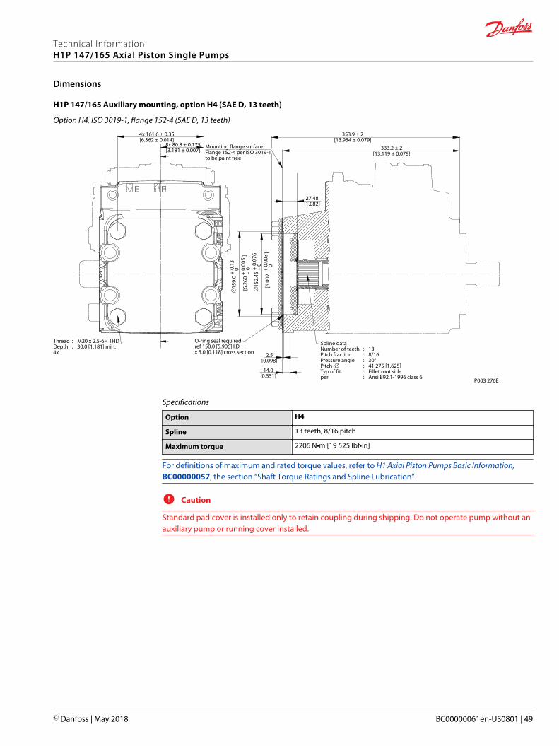
H1P 147/165 Auxiliary mounting, option H4 (SAE D, 13 teeth)
Option H4, ISO 3019-1, flange 152-4 (SAE D, 13 teeth)
4x 161.6 ± 0.35[6.362 ± 0.014]
333.2 ± 2[13.119 ± 0.079]
27.48[1.082]
353.9 ± 2[13.934 ± 0.079]
8x 80.8 ± 0.175[3.181 ± 0.007]
∅15
9.0
+ 0.
13
–
0
[6.2
60 +
0.00
5
–
0
]
∅15
2.45
+ 0.
076
– 0
[6.0
02 +
0.00
3
– 0
]
2.5[0.098]
14.0[0.551]
Thread : M20 x 2.5-6H THDDepth : 30.0 [1.181] min.4x
P003 276E
Spline dataNumber of teeth : 13Pitch fraction : 8/16Pressure angle : 30°Pitch-∅ : 41.275 [1.625]Typ of fit : Fillet root sideper : Ansi B92.1-1996 class 6
O-ring seal requiredref 150.0 [5.906] I.D. x 3.0 [0.118] cross section
Mounting flange surfaceFlange 152-4 per ISO 3019-1 to be paint free
Specifications
Option H4
Spline 13 teeth, 8/16 pitch
Maximum torque 2206 N•m [19 525 lbf•in]
For definitions of maximum and rated torque values, refer to H1 Axial Piston Pumps Basic Information,BC00000057, the section “Shaft Torque Ratings and Spline Lubrication”.
C Caution
Standard pad cover is installed only to retain coupling during shipping. Do not operate pump without anauxiliary pump or running cover installed.
Technical InformationH1P 147/165 Axial Piston Single Pumps
Dimensions
© Danfoss | May 2018 BC00000061en-US0801 | 49
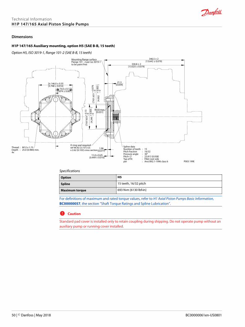
H1P 147/165 Auxiliary mounting, option H5 (SAE B-B, 15 teeth)
Option H5, ISO 3019-1, flange 101-2 (SAE B-B, 15 teeth)
2x 146.0 ± 0.35[5.748 ± 0.014]
11.4 ± 0.25[0.449 ± 0.010]
346.5 ± 2[13.642 ± 0.079]
330.8 ± 2[13.025 ± 0.079]
21.3[0.839]
4x 73.0 ± 0.175[2.874 ± 0.007]
∅10
7.82
3+ 0.
13
–
0
[4
.245
+ 0.
005
– 0
]
∅10
1.65
1 +
0.07
6
–
0[4
.002
+
0.00
3
–
0
]
1.96[0.077]
R 0.8 max.[0.031]
P003 199E
Thread : M12 x 1.75Depth : 25.0 [0.984] min.4x
Spline dataNumber of teeth : 15Pitch fraction : 16/32Pressure angle : 30°Pitch-∅ : 23.813 [0.938]Typ of fit : Fillet root sideper : Ansi B92.1-1996 class 6
O-ring seal requiredref 94.92 [3.737] I.D. x 2.62 [0.103] cross section
Mounting flange surfaceFlange 101 - 2 per iso 3019-1to be paint free
Specifications
Option H5
Spline 15 teeth, 16/32 pitch
Maximum torque 693 N•m [6130 lbf•in]
For definitions of maximum and rated torque values, refer to H1 Axial Piston Pumps Basic Information,BC00000057, the section “Shaft Torque Ratings and Spline Lubrication”.
C Caution
Standard pad cover is installed only to retain coupling during shipping. Do not operate pump without anauxiliary pump or running cover installed.
Technical InformationH1P 147/165 Axial Piston Single Pumps
Dimensions
50 | © Danfoss | May 2018 BC00000061en-US0801
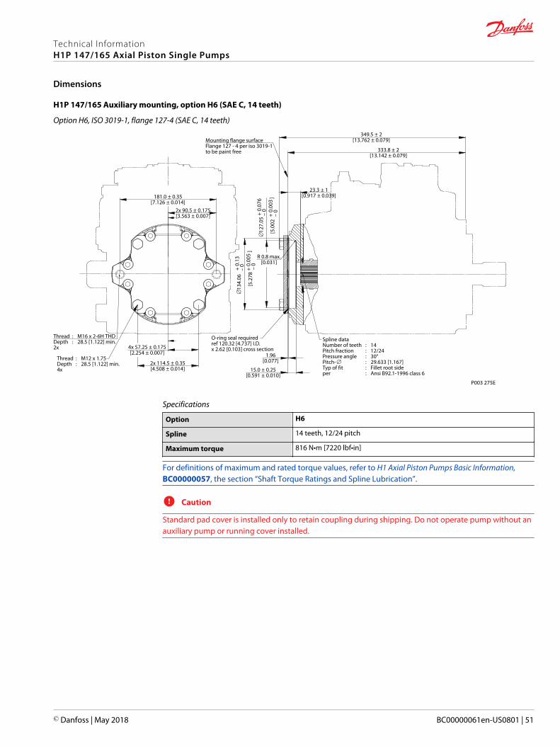
H1P 147/165 Auxiliary mounting, option H6 (SAE C, 14 teeth)
Option H6, ISO 3019-1, flange 127-4 (SAE C, 14 teeth)
2x 114.5 ± 0.35[4.508 ± 0.014] 15.0 ± 0.25
[0.591 ± 0.010]
181.0 ± 0.35[7.126 ± 0.014]
333.8 ± 2[13.142 ± 0.079]
23.3 ± 1[0.917 ± 0.039]
349.5 ± 2[13.762 ± 0.079]
4x 57.25 ± 0.175[2.254 ± 0.007]
2x 90.5 ± 0.175[3.563 ± 0.007]
∅
134.
06
+ 0.
13
– 0
[5
.278
+ 0.
005
–
0
]
∅12
7.05
+ 0.
076
– 0
[5.0
02 +
0.00
3
– 0
]
1.96[0.077]
R 0.8 max.[0.031]
P003 275E
Thread : M12 x 1.75Depth : 28.5 [1.122] min.4x
Spline dataNumber of teeth : 14Pitch fraction : 12/24Pressure angle : 30°Pitch-∅ : 29.633 [1.167]Typ of fit : Fillet root sideper : Ansi B92.1-1996 class 6
O-ring seal requiredref 120.32 [4.737] I.D. x 2.62 [0.103] cross section
Thread : M16 x 2-6H THDDepth : 28.5 [1.122] min.2x
Mounting flange surfaceFlange 127 - 4 per iso 3019-1to be paint free
Specifications
Option H6
Spline 14 teeth, 12/24 pitch
Maximum torque 816 N•m [7220 lbf•in]
For definitions of maximum and rated torque values, refer to H1 Axial Piston Pumps Basic Information,BC00000057, the section “Shaft Torque Ratings and Spline Lubrication”.
C Caution
Standard pad cover is installed only to retain coupling during shipping. Do not operate pump without anauxiliary pump or running cover installed.
Technical InformationH1P 147/165 Axial Piston Single Pumps
Dimensions
© Danfoss | May 2018 BC00000061en-US0801 | 51
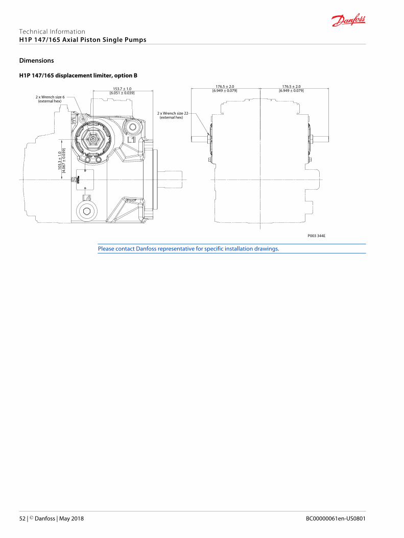
H1P 147/165 displacement limiter, option B
P003 344E
176.5 ± 2.0[6.949 ± 0.079]153.7 ± 1.0
[6.051 ± 0.039]
103.
3 ±
1.0
[4.0
67 ±
0.0
39]
176.5 ± 2.0[6.949 ± 0.079]
2 x Wrench size 22(external hex)
2 x Wrench size 6(external hex)
Please contact Danfoss representative for specific installation drawings.
Technical InformationH1P 147/165 Axial Piston Single Pumps
Dimensions
52 | © Danfoss | May 2018 BC00000061en-US0801
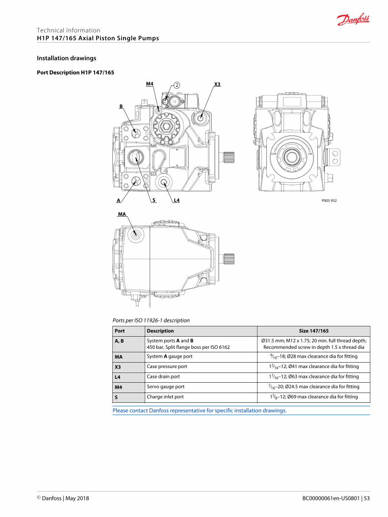
Port Description H1P 147/165
P005 932
CCW CW
L4A S
M4
B
MA
X32
Ports per ISO 11926-1 description
Port Description Size 147/165
A, B System ports A and B450 bar, Split flange boss per ISO 6162
Ø31.5 mm; M12 x 1.75; 20 min. full thread depth;Recommended screw in depth 1.5 x thread dia
MA System A gauge port 9∕16–18; Ø28 max clearance dia for fitting
X3 Case pressure port 15∕16–12; Ø41 max clearance dia for fitting
L4 Case drain port 11∕16–12; Ø63 max clearance dia for fitting
M4 Servo gauge port 7∕16–20; Ø24.5 max clearance dia for fitting
S Charge inlet port 15∕8–12; Ø69 max clearance dia for fitting
Please contact Danfoss representative for specific installation drawings.
Technical InformationH1P 147/165 Axial Piston Single Pumps
Installation drawings
© Danfoss | May 2018 BC00000061en-US0801 | 53
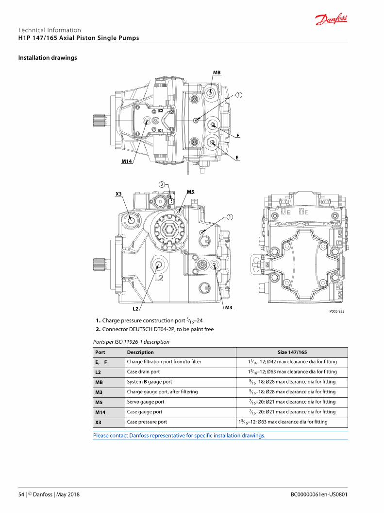
P005 933
X3
L2 M3
M5
E
F
MB
M14
1
1
2
1. Charge pressure construction port 5∕16–242. Connector DEUTSCH DT04-2P, to be paint free
Ports per ISO 11926-1 description
Port Description Size 147/165
E, F Charge filtration port from/to filter 11∕16–12; Ø42 max clearance dia for fitting
L2 Case drain port 15∕16–12; Ø63 max clearance dia for fitting
MB System B gauge port 9∕16–18; Ø28 max clearance dia for fitting
M3 Charge gauge port, after filtering 9∕16–18; Ø28 max clearance dia for fitting
M5 Servo gauge port 7∕16–20; Ø21 max clearance dia for fitting
M14 Case gauge port 7∕16–20; Ø21 max clearance dia for fitting
X3 Case pressure port 15∕16–12; Ø63 max clearance dia for fitting
Please contact Danfoss representative for specific installation drawings.
Technical InformationH1P 147/165 Axial Piston Single Pumps
Installation drawings
54 | © Danfoss | May 2018 BC00000061en-US0801
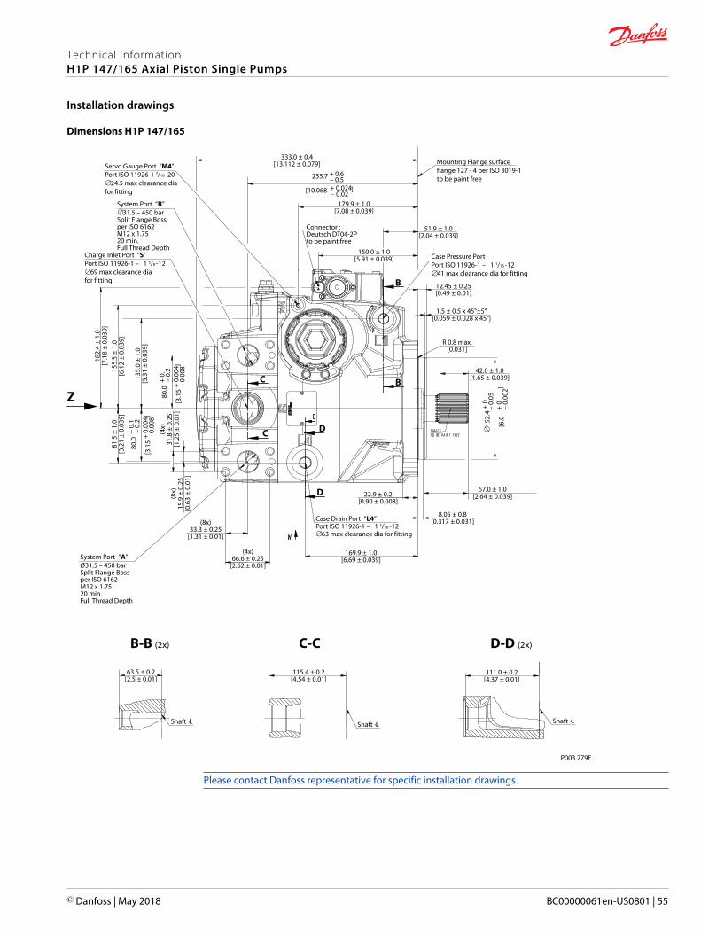
Dimensions H1P 147/165
Charge Inlet Port “S” Port ISO 11926-1 – 1 5/8 -12∅69 max clearance diafor fitting
Case Drain Port “L4” Port ISO 11926-1 – 1 5/16 -12∅63 max clearance dia for fitting
Case Pressure Port Port ISO 11926-1 – 1 1/16 -12∅41 max clearance dia for fitting
Servo Gauge Port “M4”Port ISO 11926-1 7/16 -20∅24.5 max clearance diafor fitting
System Port “B” ∅31.5 – 450 barSplit Flange Bossper ISO 6162M12 x 1.7520 min.Full Thread Depth
System Port “A” Ø31.5 – 450 barSplit Flange Bossper ISO 6162M12 x 1.7520 min.Full Thread Depth
Connector :Deutsch DT04-2Pto be paint free
Mounting Flange surfaceflange 127 - 4 per ISO 3019-1to be paint free
179.9 ± 1.0[7.08 ± 0.039]
51.9 ± 1.0[2.04 ± 0.039]
12.45 ± 0.25[0.49 ± 0.01]
169.9 ± 1.0[6.69 ± 0.039]
63.5 ± 0.2[2.5 ± 0.01]
115.4 ± 0.2[4.54 ± 0.01]
111.0 ± 0.2[4.37 ± 0.01]
(4x)66.6 ± 0.25
[2.62 ± 0.01]
(8x)33.3 ± 0.25
[1.31 ± 0.01]
(4x)
31.8
± 0
.25
[1.2
5 ±
0.01
]
81.5
± 1
.0[3
.21
± 0.
039]
135.
0 ±
1.0
[5.3
1 ±
0.03
9]
155.
5 ±
1.0
[6.1
2 ±
0.03
9]
(8x)
15.9
± 0
.25
[0.6
3 ±
0.01
]
R 0.8 max.[0.031]
333.0 ± 0.4[13.112 ± 0.079]
1.5 ± 0.5 x 45°±5°[0.059 ± 0.028 x 45°]
∅15
2.4
+ 0
– 0
.05
[6.
0
+ 0
– 0.
002]
80.
0 +
0.1
–
0.2
[3
.15
+ 0.
004
– 0.
008]
80.
0 +
0.1
–
0.2
[3
.15
+ 0.
004
– 0.
008]
255.7 + 0.6 – 0.5
[10.068 + 0.024
– 0.02
]
P003 279E
B-B (2x)
Z
D-D (2x)C-C
B
BC
C D
D
Shaft Lc Shaft Lc Shaft Lc
150.0 ± 1.0[5.91 ± 0.039]
8.05 ± 0.8[0.317 ± 0.031]
67.0 ± 1.0[2.64 ± 0.039]
42.0 ± 1.0[1.65 ± 0.039]
22.9 ± 0.2[0.90 ± 0.008]
182.
4 ±
1.0
[7.1
8 ±
0.03
9]
Please contact Danfoss representative for specific installation drawings.
Technical InformationH1P 147/165 Axial Piston Single Pumps
Installation drawings
© Danfoss | May 2018 BC00000061en-US0801 | 55
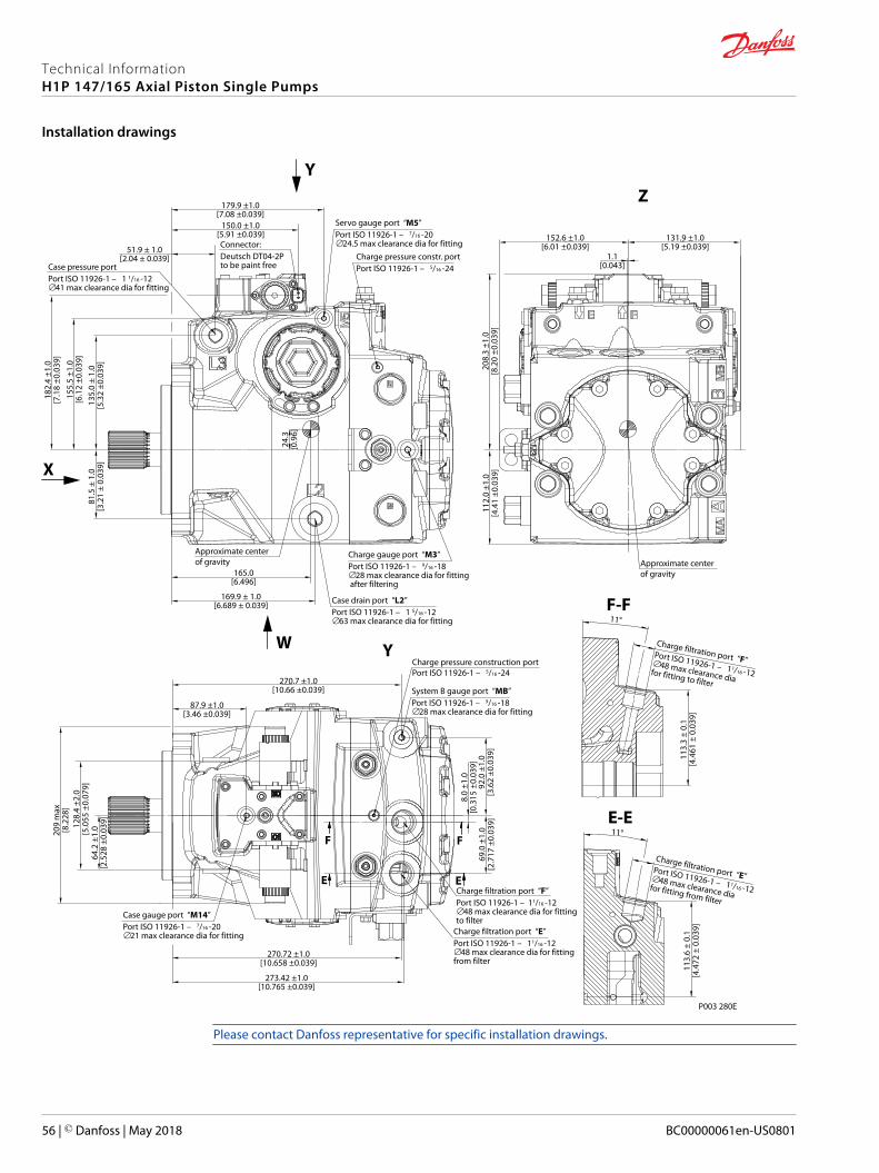
ZY
X
W Y
Case pressure port Port ISO 11926-1 – 1 1/16 -12∅41 max clearance dia for fitting
Case drain port “L2” Port ISO 11926-1 – 1 5/16 -12∅63 max clearance dia for fitting
Servo gauge port “M5” Port ISO 11926-1 – 7/16 -20∅24.5 max clearance dia for fitting
Charge gauge port “M3” Port ISO 11926-1 – 9/16 -18∅28 max clearance dia for fitting after filtering
Charge pressure constr. port Port ISO 11926-1 – 5/16 -24
Approximate centerof gravity
Approximate centerof gravity
51.9 ± 1.0[2.04 ± 0.039]
81.5
± 1
.0[3
.21
± 0.
039]
135.
0 ±
1.0
[5.3
2 ±0
.039
]
24.3
[0.9
6]
155.
5 ±1
.0[6
.12
±0.0
39]
150.0 ±1.0[5.91 ±0.039] 152.6 ±1.0
[6.01 ±0.039]131.9 ±1.0
[5.19 ±0.039]1.1
[0.043]
165.0[6.496]
169.9 ± 1.0[6.689 ± 0.039]
Charge pressure construction port Port ISO 11926-1 – 5/16 -24
92.0
±1.
0[3
.62
±0.0
39]
270.7 ±1.0[10.66 ±0.039]
273.42 ±1.0[10.765 ±0.039]
270.72 ±1.0[10.658 ±0.039]
8.0
±1.0
[0.3
15 ±
0.03
9]69
.0 ±
1.0
[2.7
17 ±
0.03
9]
F
E
System B gauge port “MB”Port ISO 11926-1 – 9/16 -18∅28 max clearance dia for fitting
Charge filtration port “F” Port ISO 11926-1 – 11/16 -12∅48 max clearance dia for fittingto filter
Charge filtration port “E” Port ISO 11926-1 – 11/16 -12∅48 max clearance dia for fittingfrom filter
Case gauge port “M14” Port ISO 11926-1 – 7/16 -20∅21 max clearance dia for fitting
112.
0 ±1
.0[4
.41
±0.0
39]
208.
3 ±1
.0[8
.20
±0.0
39]
E
182.
4 ±1
.0[7
.18
±0.0
39]
179.9 ±1.0[7.08 ±0.039]
Connector:Deutsch DT04-2Pto be paint free
64.2
±1.
0[2
.528
±0.
039]
209
max
[8.2
28]
128.
4 ±2
.0[5
.055
±0.
079]
87.9 ±1.0[3.46 ±0.039]
F
P003 280E
11°E-E
Charge filtration port “E” Port ISO 11926-1 – 11/16 -12∅48 max clearance dia for fitting from filter
113.
6 ±
0.1
[4.4
72 ±
0.0
39]
11°F-F
Charge filtration port “F” Port ISO 11926-1 – 11/16 -12∅48 max clearance dia for fitting to filter
113.
3 ±
0.1
[4.4
61 ±
0.0
39]
Please contact Danfoss representative for specific installation drawings.
Technical InformationH1P 147/165 Axial Piston Single Pumps
Installation drawings
56 | © Danfoss | May 2018 BC00000061en-US0801
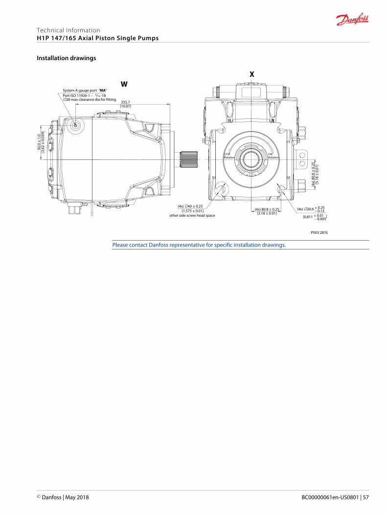
(4x) ∅20.6 + 0.25 – 0.13 [0.811 + 0.01
– 0.005
]
(4x) 80.8 ± 0.25[3.18 ± 0.01]
(4x)
80.
8 ±
0.25
[3.1
8 ±
0.01
]
255.7[10.07]
P003 281E
92.0
± 1
.0[3
.62
± 0.
039]
WX
System A gauge port “MA” Port ISO 11926-1 – 9/16 -18∅28 max clearance dia for fitting
CCWRotation
CWRotation
(4x) ∅40 ± 0.25 [1.575 ± 0.01]
other side screw head space
Please contact Danfoss representative for specific installation drawings.
Technical InformationH1P 147/165 Axial Piston Single Pumps
Installation drawings
© Danfoss | May 2018 BC00000061en-US0801 | 57
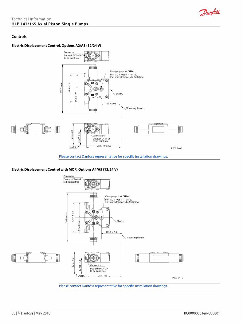
Electric Displacement Control, Options A2/A3 (12/24 V)
245
± 2.
5
P003 340E
2x 2
19 ±
1.2
2x 171.0 ± 1.2
128.
4 ±
2.0
64.2
± 1
.0209.
0 m
ax
109.9 ± 0.8
Connector :Deutsch DT04-2Pto be paint free
Case gauge port “M14” Port ISO 11926-1 – 7/16 -20∅21 max clearance dia for fitting
Shaft Lc
Mounting flange
Connector :Deutsch DT04-2Pto be paint free
Shaft Lc
Please contact Danfoss representative for specific installation drawings.
Electric Displacement Control with MOR, Options A4/A5 (12/24 V)
Shaft Lc
Mounting flange
Connector :Deutsch DT04-2Pto be paint free
P003 341EShaft Lc
245
±2.5
2x 2
19 ±
1.2
2x 171 ± 1.2
128.
4 ±
2.0
64.2
± 1
.0209.
0 m
ax
109.9 ± 0.8
Case gauge port “M14” Port ISO 11926-1 – 7/16 -20∅21 max clearance dia for fitting
Connector :Deutsch DT04-2Pto be paint free
Please contact Danfoss representative for specific installation drawings.
Technical InformationH1P 147/165 Axial Piston Single Pumps
Controls
58 | © Danfoss | May 2018 BC00000061en-US0801
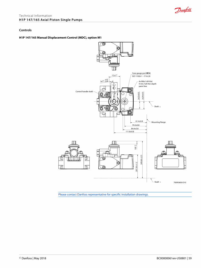
H1P 147/165 Manual Displacement Control (MDC), option M1
70095400-D10
Mounting flange61.4±0.8
79.2±0.8
84.4±0.8111.8±0.8
9.8
+1
249.
66 ±
2.5
207.
56 ±
1.2
Shaft
0
2x22
±0.5
2x24
±0.5
4x M6x1-6H thd.9 min. full thd. depthpaint free
Case gauge port M14ISO 11926-1 -7/16-20
Shaft
7.5±1°
3x11 -0.02
-0.08
Control handle shaft
Please contact Danfoss representative for specific installation drawings.
Technical InformationH1P 147/165 Axial Piston Single Pumps
Controls
© Danfoss | May 2018 BC00000061en-US0801 | 59
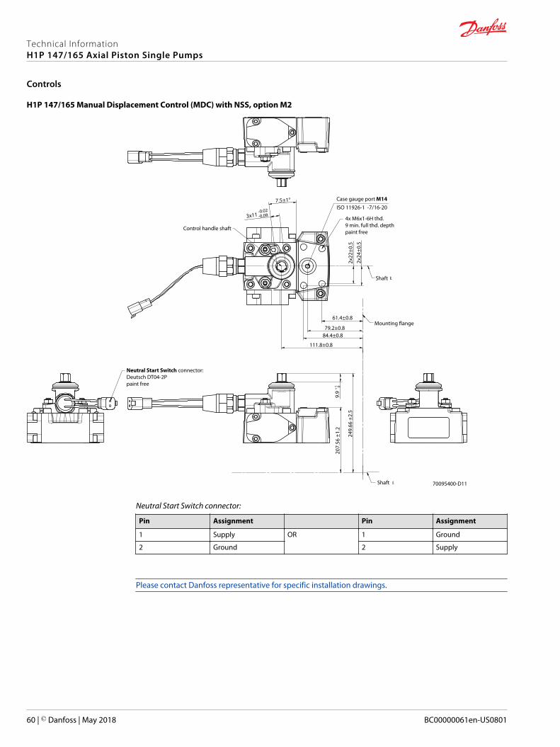
H1P 147/165 Manual Displacement Control (MDC) with NSS, option M2
Mounting flange
2x22
±0.5
2x24
±0.5
7.5±1°
3x11 -0.02
-0.08
4x M6x1-6H thd.9 min. full thd. depthpaint free
Neutral Start Switch connector:Deutsch DT04-2Ppaint free
Case gauge port M14ISO 11926-1 -7/16-20
Shaft
Control handle shaft
Shaft
9.9
+1 0
70095400-D11
61.4±0.8
79.2±0.884.4±0.8
111.8±0.824
9.66
±2.
5
207.
56 ±
1.2
Neutral Start Switch connector:
Pin Assignment Pin Assignment
1 Supply OR 1 Ground
2 Ground 2 Supply
Please contact Danfoss representative for specific installation drawings.
Technical InformationH1P 147/165 Axial Piston Single Pumps
Controls
60 | © Danfoss | May 2018 BC00000061en-US0801
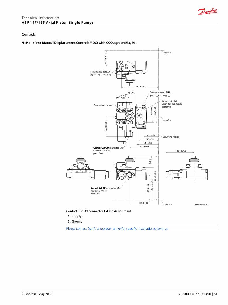
H1P 147/165 Manual Displacement Control (MDC) with CCO, option M3, M4
Mounting flange
140.4 ±1.2
111.4 ±0.8
98.774±1.52x
22±0
.59.
8 +1
182.
3 ±0
.8
2x24
±0.5
7.5±1°
3x11 -0.02
-0.08
4x M6x1-6H thd.9 min. full thd. depthpaint free
Shaft
Control handle shaft
Shaft
0
Control Cut Off connector C4:Deutsch DT04-2Ppaint free
Control Cut Off connector C4:Deutsch DT04-2Ppaint free
Case gauge port M14ISO 11926-1 -7/16-20
Brake gauge port X7ISO 11926-1 -7/16-20
182.
26 ±
1.2
70095400-D12
72.1
5±0.
8
Shaft
61.4±0.8
79.2±0.8
84.4±0.8
111.8±0.8
249.
66 ±
2.5
207.
56 ±
1.2
Control Cut Off connector C4 Pin Assignment:1. Supply2. Ground
Please contact Danfoss representative for specific installation drawings.
Technical InformationH1P 147/165 Axial Piston Single Pumps
Controls
© Danfoss | May 2018 BC00000061en-US0801 | 61
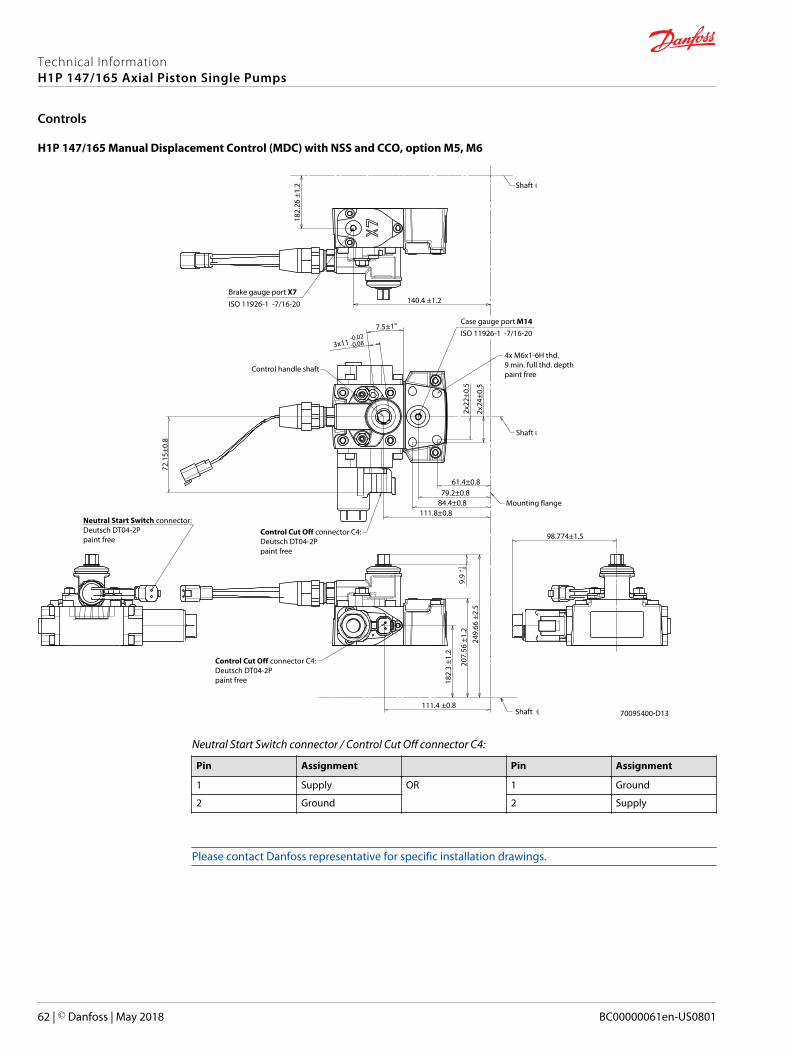
H1P 147/165 Manual Displacement Control (MDC) with NSS and CCO, option M5, M6
Mounting flange
2x22
±0.5
2x24
±0.5
7.5±1°
3x11 -0.02
-0.08
4x M6x1-6H thd.9 min. full thd. depthpaint free
Neutral Start Switch connector:Deutsch DT04-2Ppaint free
Case gauge port M14ISO 11926-1 -7/16-20
Shaft
Control handle shaft
Shaft
9.9
+1 0
Control Cut Off connector C4:Deutsch DT04-2Ppaint free
Brake gauge port X7ISO 11926-1 -7/16-20
72.1
5±0.
8
98.774±1.5Control Cut Off connector C4:Deutsch DT04-2Ppaint free
Shaft
140.4 ±1.2
111.4 ±0.8
182.
3 ±1
.2
182.
26 ±
1.2
70095400-D13
61.4±0.879.2±0.8
84.4±0.8111.8±0.8
249.
66 ±
2.5
207.
56 ±
1.2
Neutral Start Switch connector / Control Cut Off connector C4:
Pin Assignment Pin Assignment
1 Supply OR 1 Ground
2 Ground 2 Supply
Please contact Danfoss representative for specific installation drawings.
Technical InformationH1P 147/165 Axial Piston Single Pumps
Controls
62 | © Danfoss | May 2018 BC00000061en-US0801
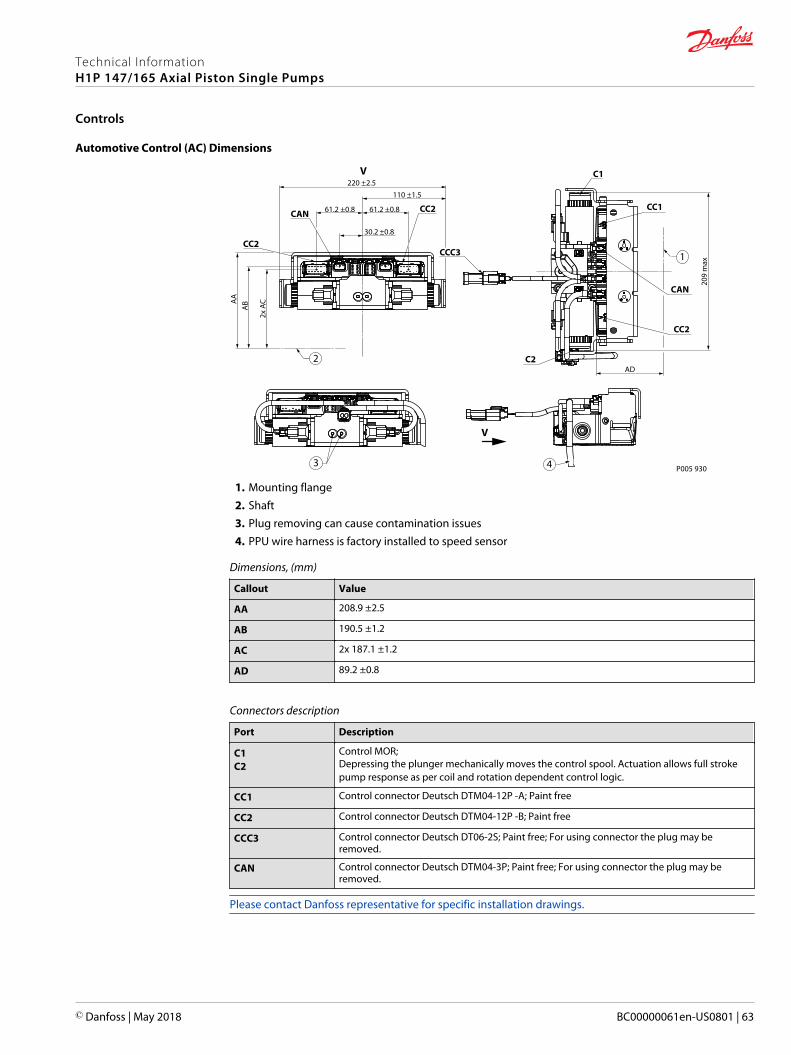
Automotive Control (AC) Dimensions
61.2 ±0.8 61.2 ±0.8
30.2 ±0.8A
AA
B
2x A
C
C1
CAN
CC2
CC2
C2
V
209
max
AD
V
P005 93043
1
2
CAN
CC1
CC2CCC3
220 ±2.5110 ±1.5
1. Mounting flange2. Shaft3. Plug removing can cause contamination issues4. PPU wire harness is factory installed to speed sensor
Dimensions, (mm)
Callout Value
AA 208.9 ±2.5
AB 190.5 ±1.2
AC 2x 187.1 ±1.2
AD 89.2 ±0.8
Connectors description
Port Description
C1C2
Control MOR;Depressing the plunger mechanically moves the control spool. Actuation allows full strokepump response as per coil and rotation dependent control logic.
CC1 Control connector Deutsch DTM04-12P -A; Paint free
CC2 Control connector Deutsch DTM04-12P -B; Paint free
CCC3 Control connector Deutsch DT06-2S; Paint free; For using connector the plug may beremoved.
CAN Control connector Deutsch DTM04-3P; Paint free; For using connector the plug may beremoved.
Please contact Danfoss representative for specific installation drawings.
Technical InformationH1P 147/165 Axial Piston Single Pumps
Controls
© Danfoss | May 2018 BC00000061en-US0801 | 63
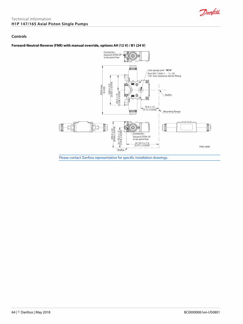
Forward-Neutral-Reverse (FNR) with manual override, options A9 (12 V) / B1 (24 V)
P003 400E
Shaft Lc
Mounting flange
Shaft Lc
Connector :Deutsch DT04-2Pto be paint free20
4.3
± 2.
0[8
.042
± 0
.079
]
128.
4 ±
2.0
[5.0
55 ±
0.0
79]
64.2
± 1
.0[2
.528
± 0
.039
]2x
178
.3 ±
1.0
[7.0
18 ±
0.0
39]
2x 141.5 ± 1.0[5.571 ± 0.039]
209.
0 m
ax[8
.228
]79.4 ± 1.0
[3.13 ± 0.039]
Case gauge port “M14” Port ISO 11926-1 – 7/16 -20∅21 max clearance dia for fitting
Connector :Deutsch DT04-2Pto be paint free
Please contact Danfoss representative for specific installation drawings.
Technical InformationH1P 147/165 Axial Piston Single Pumps
Controls
64 | © Danfoss | May 2018 BC00000061en-US0801
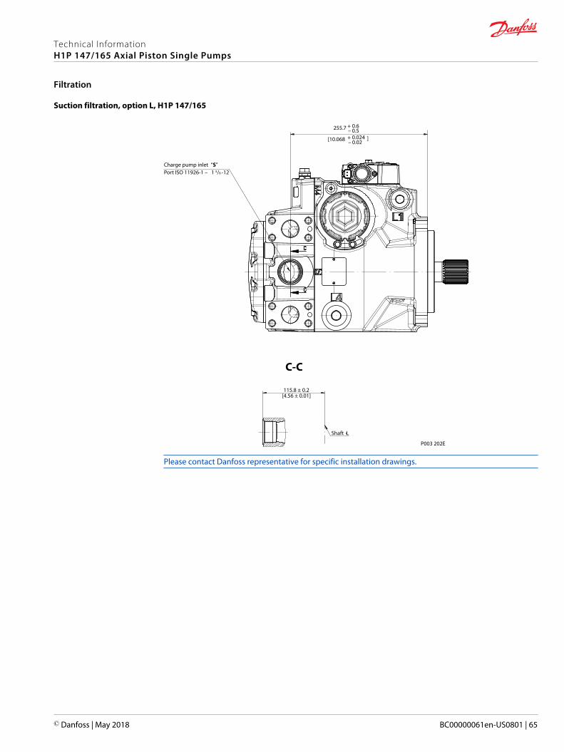
Suction filtration, option L, H1P 147/165
115.8 ± 0.2[4.56 ± 0.01]
C-C
Shaft Lc
P003 202E
Charge pump inlet “S” Port ISO 11926-1 – 1 5/8 -12
255.7 + 0.6 – 0.5
[10.068 + 0.024
– 0.02
]
Please contact Danfoss representative for specific installation drawings.
Technical InformationH1P 147/165 Axial Piston Single Pumps
Filtration
© Danfoss | May 2018 BC00000061en-US0801 | 65
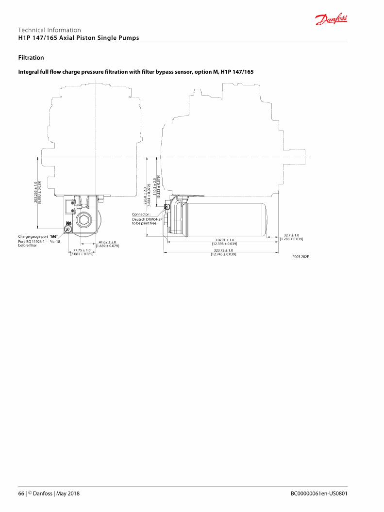
Integral full flow charge pressure filtration with filter bypass sensor, option M, H1P 147/165
P003 282E
Connector :Deutsch DTM04-2Pto be paint free
203.
265
± 1.
0[8
.003
± 0
.039
]
77.75 ± 1.0[3.061 ± 0.039]
314.91 ± 1.0[12.398 ± 0.039]
32.7 ± 1.0[1.288 ± 0.039]
323.72 ± 1.0[12.745 ± 0.039]
140.
3 ±
2.0
[5.5
22 ±
0.0
79]
226.
0 ±
2.0
[8.8
84 ±
0.0
79]
Charge gauge port “M6” Port ISO 11926-1 – 9/16 -18before filter
41.62 ± 2.0[1.639 ± 0.079]
Technical InformationH1P 147/165 Axial Piston Single Pumps
Filtration
66 | © Danfoss | May 2018 BC00000061en-US0801

Technical InformationH1P 147/165 Axial Piston Single Pumps
© Danfoss | May 2018 BC00000061en-US0801 | 67
Danfoss Power Solutions is a global manufacturer and supplier of high-quality hydraulic andelectronic components. We specialize in providing state-of-the-art technology and solutionsthat excel in the harsh operating conditions of the mobile off-highway market. Building onour extensive applications expertise, we work closely with our customers to ensureexceptional performance for a broad range of off-highway vehicles.
We help OEMs around the world speed up system development, reduce costs and bringvehicles to market faster.
Danfoss – Your Strongest Partner in Mobile Hydraulics.
Go to www.powersolutions.danfoss.com for further product information.
Wherever off-highway vehicles are at work, so is Danfoss. We offer expert worldwide supportfor our customers, ensuring the best possible solutions for outstanding performance. Andwith an extensive network of Global Service Partners, we also provide comprehensive globalservice for all of our components.
Please contact the Danfoss Power Solution representative nearest you.
Local address:
Danfoss Power Solutions GmbH & Co. OHGKrokamp 35D-24539 Neumünster, GermanyPhone: +49 4321 871 0
Danfoss Power Solutions ApSNordborgvej 81DK-6430 Nordborg, DenmarkPhone: +45 7488 2222
Danfoss Power Solutions (US) Company2800 East 13th StreetAmes, IA 50010, USAPhone: +1 515 239 6000
Danfoss Power Solutions Trading(Shanghai) Co., Ltd.Building #22, No. 1000 Jin Hai RdJin Qiao, Pudong New DistrictShanghai, China 201206Phone: +86 21 3418 5200
Danfoss can accept no responsibility for possible errors in catalogues, brochures and other printed material. Danfoss reserves the right to alter its products without notice. This also applies to productsalready on order provided that such alterations can be made without changes being necessary in specifications already agreed.All trademarks in this material are property of the respective companies. Danfoss and the Danfoss logotype are trademarks of Danfoss A/S. All rights reserved.
© Danfoss | May 2018 BC00000061en-US0801
Products we offer:
• Bent Axis Motors
• Closed Circuit Axial PistonPumps and Motors
• Displays
• Electrohydraulic PowerSteering
• Electrohydraulics
• Hydraulic Power Steering
• Integrated Systems
• Joysticks and ControlHandles
• Microcontrollers andSoftware
• Open Circuit Axial PistonPumps
• Orbital Motors
• PLUS+1® GUIDE
• Proportional Valves
• Sensors
• Steering
• Transit Mixer Drives
Comatrolwww.comatrol.com
Turolla www.turollaocg.com
Hydro-Gearwww.hydro-gear.com
Daikin-Sauer-Danfosswww.daikin-sauer-danfoss.com
Recommended