GHB 13.0002-EN.ùCh
Ä.-Chä
Hardware Manual
L-force | Servo Drives 930 fluxxtorque
931M/W
Servo inverter
Please read these Instructions before you start working!
Follow the enclosed safety instructions.
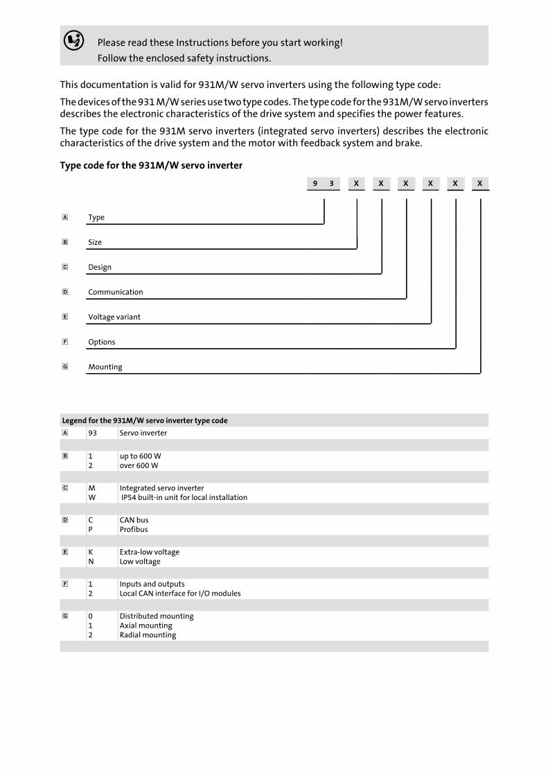
This documentation is valid for 931M/W servo inverters using the following type code:
Thedevicesof the931M/Wseriesuse twotypecodes. The typecode for the931M/Wservo invertersdescribes the electronic characteristics of the drive system and specifies the power features.
The type code for the 931M servo inverters (integrated servo inverters) describes the electroniccharacteristics of the drive system and the motor with feedback system and brake.
Type code for the 931M/W servo inverter
9 3 X X X X X X
Type
Size
Design
Communication
Voltage variant
Options
Mounting
Legend for the 931M/W servo inverter type code
93 Servo inverter
12
up to 600Wover 600W
MW
Integrated servo inverterIP54 built-in unit for local installation
CP
CAN busProfibus
KN
Extra-low voltageLow voltage
12
Inputs and outputsLocal CAN interface for I/Omodules
012
Distributed mountingAxial mountingRadial mounting
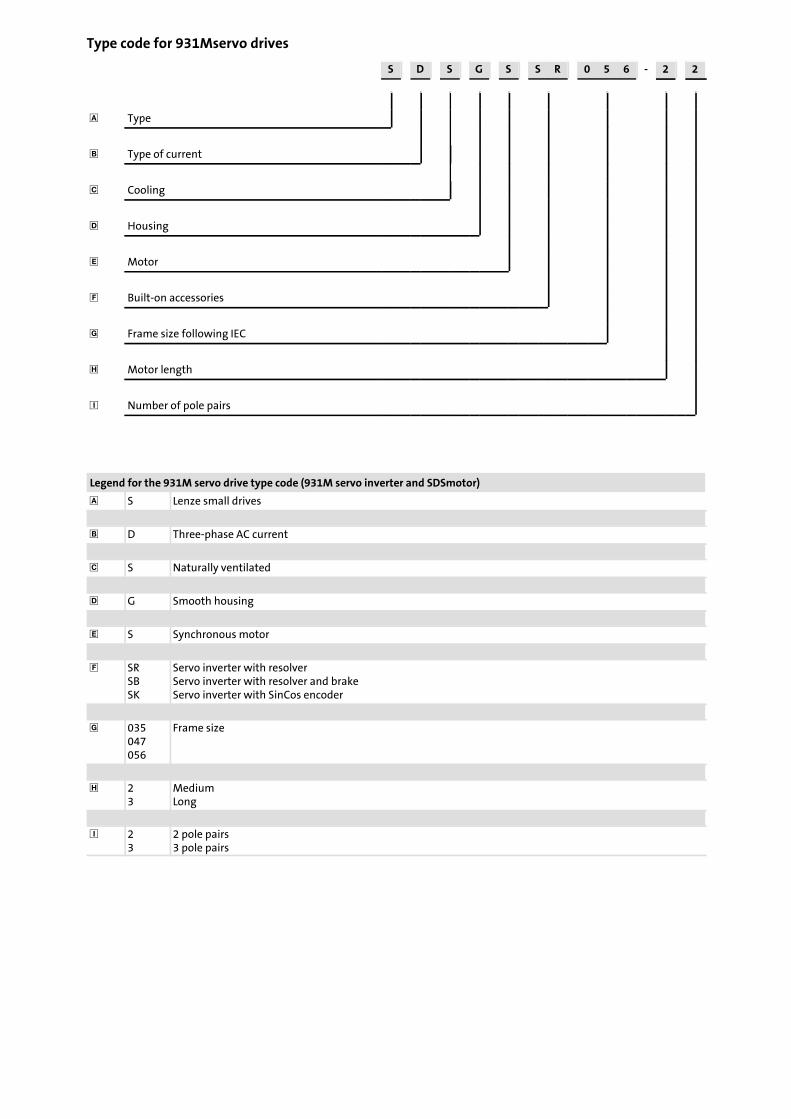
Type code for 931Mservo drives
S D S G S S R 0 5 6 - 2 2
Type
Type of current
Cooling
Housing
Motor
Built-on accessories
Frame size following IEC
Motor length
Number of pole pairs
Legend for the 931M servo drive type code (931M servo inverter and SDSmotor)
S Lenze small drives
D Three-phase AC current
S Naturally ventilated
G Smooth housing
S Synchronous motor
SRSBSK
Servo inverter with resolverServo inverter with resolver and brakeServo inverter with SinCos encoder
035047056
Frame size
23
MediumLong
23
2 pole pairs3 pole pairs
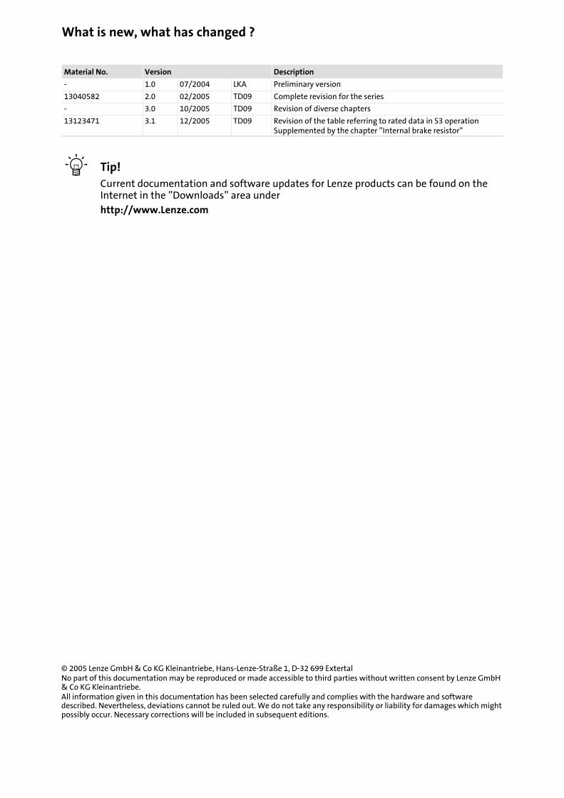
What is new, what has changed ?
Material No. Version Description
- 1.0 07/2004 LKA Preliminary version
13040582 2.0 02/2005 TD09 Complete revision for the series
- 3.0 10/2005 TD09 Revision of diverse chapters
13123471 3.1 12/2005 TD09 Revision of the table referring to rated data in S3 operationSupplemented by the chapter ”Internal brake resistor”
Tip!Current documentation and software updates for Lenze products can be found on theInternet in the ”Downloads” area underhttp://www.Lenze.com
© 2005 Lenze GmbH& Co KG Kleinantriebe, Hans-Lenze-Straße 1, D-32 699 ExtertalNo part of this documentation may be reproduced or made accessible to third parties without written consent by Lenze GmbH& Co KG Kleinantriebe.All information given in this documentation has been selected carefully and complies with the hardware and softwaredescribed. Nevertheless, deviations cannot be ruled out. We do not take any responsibility or liability for damages which mightpossibly occur. Necessary corrections will be included in subsequent editions.
Contents i
5GHB 13.0002-EN 3.1
1 Preface and general information 9. . . . . . . . . . . . . . . . . . . . . . . . . . . . . . . . . . . . . . . . . . . .
1.1 About this Manual 9. . . . . . . . . . . . . . . . . . . . . . . . . . . . . . . . . . . . . . . . . . . . . . . . . . . .
1.2 Terminology used 9. . . . . . . . . . . . . . . . . . . . . . . . . . . . . . . . . . . . . . . . . . . . . . . . . . . .
1.3 Scope of supply 10. . . . . . . . . . . . . . . . . . . . . . . . . . . . . . . . . . . . . . . . . . . . . . . . . . . . . .
1.4 Legal regulations 10. . . . . . . . . . . . . . . . . . . . . . . . . . . . . . . . . . . . . . . . . . . . . . . . . . . . .
2 Safety instructions 11. . . . . . . . . . . . . . . . . . . . . . . . . . . . . . . . . . . . . . . . . . . . . . . . . . . . . . . . .
2.1 Personnel responsible for safety 11. . . . . . . . . . . . . . . . . . . . . . . . . . . . . . . . . . . . . . . .
2.2 General safety and application notes for Lenze controllers 11. . . . . . . . . . . . . . . . . .
2.3 General safety information 13. . . . . . . . . . . . . . . . . . . . . . . . . . . . . . . . . . . . . . . . . . . .
2.4 Residual hazards 14. . . . . . . . . . . . . . . . . . . . . . . . . . . . . . . . . . . . . . . . . . . . . . . . . . . . .
2.9 Definition of notes used 15. . . . . . . . . . . . . . . . . . . . . . . . . . . . . . . . . . . . . . . . . . . . . . .
3 Technical data 16. . . . . . . . . . . . . . . . . . . . . . . . . . . . . . . . . . . . . . . . . . . . . . . . . . . . . . . . . . . .
3.1 Features 16. . . . . . . . . . . . . . . . . . . . . . . . . . . . . . . . . . . . . . . . . . . . . . . . . . . . . . . . . . . .
3.2 Design 16. . . . . . . . . . . . . . . . . . . . . . . . . . . . . . . . . . . . . . . . . . . . . . . . . . . . . . . . . . . . . .
3.3 Rated data 18. . . . . . . . . . . . . . . . . . . . . . . . . . . . . . . . . . . . . . . . . . . . . . . . . . . . . . . . . .3.3.1 General data and operating conditions 18. . . . . . . . . . . . . . . . . . . . . . . . . .3.3.2 Internal brake resistor 19. . . . . . . . . . . . . . . . . . . . . . . . . . . . . . . . . . . . . . . . .3.3.3 Rated data of the extra-low voltage version (24 or 42 V DC) 20. . . . . . . . .3.3.4 Rated data of the low-voltage version (230 V AC / 320 V DC) 20. . . . . . . .3.3.5 Rated data of the drive systems 21. . . . . . . . . . . . . . . . . . . . . . . . . . . . . . . .3.3.6 Rated data for S3 operation/overload capacity 23. . . . . . . . . . . . . . . . . . . .
3.4 Connection cables 24. . . . . . . . . . . . . . . . . . . . . . . . . . . . . . . . . . . . . . . . . . . . . . . . . . . .3.4.1 System cable for 931M/W voltage supply 24. . . . . . . . . . . . . . . . . . . . . . . . .3.4.2 Connection cables for bus systems 25. . . . . . . . . . . . . . . . . . . . . . . . . . . . . .3.4.3 Connecting cables 26. . . . . . . . . . . . . . . . . . . . . . . . . . . . . . . . . . . . . . . . . . . .
4 Mechanical installation 27. . . . . . . . . . . . . . . . . . . . . . . . . . . . . . . . . . . . . . . . . . . . . . . . . . . . .
4.1 Important notes 27. . . . . . . . . . . . . . . . . . . . . . . . . . . . . . . . . . . . . . . . . . . . . . . . . . . . . .
4.2 Mechanical installation of 931M 28. . . . . . . . . . . . . . . . . . . . . . . . . . . . . . . . . . . . . . .
4.3 Mechanical installation of 931W 28. . . . . . . . . . . . . . . . . . . . . . . . . . . . . . . . . . . . . . .
4.4 Mounting plate for 931W 29. . . . . . . . . . . . . . . . . . . . . . . . . . . . . . . . . . . . . . . . . . . . .
5 Electrical installation 30. . . . . . . . . . . . . . . . . . . . . . . . . . . . . . . . . . . . . . . . . . . . . . . . . . . . . . .
5.1 Important notes 30. . . . . . . . . . . . . . . . . . . . . . . . . . . . . . . . . . . . . . . . . . . . . . . . . . . . . .
5.3 Installation according to EMC (installation of a CE-typical drive system) 31. . . . . . .
5.4 Electrical connections of 931M, 24 V DC / 42 V DC 32. . . . . . . . . . . . . . . . . . . . . . . . .
5.5 Electrical connections of 931M, 230 V AC / 320 V DC 34. . . . . . . . . . . . . . . . . . . . . . .
5.6 Electrical connections of 931W, 230V AC / 320V DC 36. . . . . . . . . . . . . . . . . . . . . . .
Contentsi
6 GHB 13.0002-EN 3.1
6 Commissioning 34. . . . . . . . . . . . . . . . . . . . . . . . . . . . . . . . . . . . . . . . . . . . . . . . . . . . . . . . . . .
6.1 Before switching on 34. . . . . . . . . . . . . . . . . . . . . . . . . . . . . . . . . . . . . . . . . . . . . . . . . .6.1.1 Voltage supply connection 34. . . . . . . . . . . . . . . . . . . . . . . . . . . . . . . . . . . . .6.1.2 Motor connection 34. . . . . . . . . . . . . . . . . . . . . . . . . . . . . . . . . . . . . . . . . . . . .6.1.3 External inputs and outputs / connection with local CAN devices 35. . . .6.1.4 Bus cable connections 35. . . . . . . . . . . . . . . . . . . . . . . . . . . . . . . . . . . . . . . . .6.1.5 Connection of the connecting cable between PC and servo inverter 35. . .6.1.6 Covers for the power connections 35. . . . . . . . . . . . . . . . . . . . . . . . . . . . . . .
7 Application example 36. . . . . . . . . . . . . . . . . . . . . . . . . . . . . . . . . . . . . . . . . . . . . . . . . . . . . . .
7.1 Preconditions 36. . . . . . . . . . . . . . . . . . . . . . . . . . . . . . . . . . . . . . . . . . . . . . . . . . . . . . .
7.2 General information 36. . . . . . . . . . . . . . . . . . . . . . . . . . . . . . . . . . . . . . . . . . . . . . . . . .
7.3 Menu pages 36. . . . . . . . . . . . . . . . . . . . . . . . . . . . . . . . . . . . . . . . . . . . . . . . . . . . . . . . .7.3.1 Setup menu page 36. . . . . . . . . . . . . . . . . . . . . . . . . . . . . . . . . . . . . . . . . . . . .7.3.2 Status menu page 38. . . . . . . . . . . . . . . . . . . . . . . . . . . . . . . . . . . . . . . . . . . .7.3.3 Driving programmenu page 39. . . . . . . . . . . . . . . . . . . . . . . . . . . . . . . . . . . .
8 Troubleshooting and fault elimination 9-3-41. . . . . . . . . . . . . . . . . . . . . . . . . . . . . . . . . . . . . . .
8.1 Fault elimination for general errors 9-3-41. . . . . . . . . . . . . . . . . . . . . . . . . . . . . . . . . . . . .
8.2 Fault elimination for known error message (see Fluxx, ”Status” tab) 9-3-42. . . . . . . . .
8.3 Fault elimination for errors / problems with regard to the handling of bus systems . . . . .9-3-44
9 Accessories 44. . . . . . . . . . . . . . . . . . . . . . . . . . . . . . . . . . . . . . . . . . . . . . . . . . . . . . . . . . . . . . .
9.1 Technical documentation 44. . . . . . . . . . . . . . . . . . . . . . . . . . . . . . . . . . . . . . . . . . . . .
9.2 Power supply units 44. . . . . . . . . . . . . . . . . . . . . . . . . . . . . . . . . . . . . . . . . . . . . . . . . . .
9.3 Functionmodules for 930 series (M/W) 45. . . . . . . . . . . . . . . . . . . . . . . . . . . . . . . . . .
10 Appendix 47. . . . . . . . . . . . . . . . . . . . . . . . . . . . . . . . . . . . . . . . . . . . . . . . . . . . . . . . . . . . . . . .
10.1 Dimensions of 931M 24 V or 42 V DC, simple mounting (resolver) 47. . . . . . . . . . . .
10.2 Dimensions of 931M 230 V AC or 320 V DC, simple mounting (resolver) 48. . . . . . .
10.3 Dimensions of 931M 24 V or 42 V DC, double mounting (resolver + brake) 49. . . . .
10.4 Dimensions of 931M 230 V AC or 320 V DC, double mounting (resolver + brake) 50
10.5 Voltage supply for type 931M 24 V or 42 V 51. . . . . . . . . . . . . . . . . . . . . . . . . . . . . . .
10.6 Voltage supply for type 931M 230 V or 320 V 52. . . . . . . . . . . . . . . . . . . . . . . . . . . . .
10.7 Profibus connection 53. . . . . . . . . . . . . . . . . . . . . . . . . . . . . . . . . . . . . . . . . . . . . . . . . . .
10.8 CAN connection 54. . . . . . . . . . . . . . . . . . . . . . . . . . . . . . . . . . . . . . . . . . . . . . . . . . . . . .
10.9 RS232 connection 55. . . . . . . . . . . . . . . . . . . . . . . . . . . . . . . . . . . . . . . . . . . . . . . . . . . .
10.10 Local CAN or digital I/O connection 56. . . . . . . . . . . . . . . . . . . . . . . . . . . . . . . . . . . . .
11 Table of keywords 57. . . . . . . . . . . . . . . . . . . . . . . . . . . . . . . . . . . . . . . . . . . . . . . . . . . . . . . . .
Preface and general informationAbout this Manual
1
7GHB 13.0002-EN 3.1
1 Preface and general information
1.1 About this Manual
Target group
ThisManualaddresses toallpersonsdesigning,mounting, commissioningandsetting theservo inverters of the 931 series.
Togetherwith the catalog, it presents the project documents for themechanical engineerand the system engineer.
Contents
The System Manual supplements the Mounting Instructions contained in the scope ofsupply:
ƒ The features and functions are described in detail.
ƒ It provides detailed information on the possible applications.
ƒ The parameter setting is clarified by examples.
ƒ In case of doubt, the supplied Mounting Instructions always apply.
Finding information
ƒ Via the contents and index, you quickly find the information regarding a specificproblem.
ƒ Descriptions and data with regard to other Lenze products can be gathered from therespective catalogs, Operating Instructions and Manuals. ( 49)
ƒ You can request Lenze documentation from your responsible Lenze sales partner, ordownload it from the Internet as a PDF file.
1.2 Terminology used
Term In the following text used for
931M/W 931M or 931W servo inverter
Controller 931M/W servo inverter
Drive 931M servo inverter or 931W servo inverter with motor
Preface and general informationScope of supply
1
8 GHB 13.0002-EN 3.1
1.3 Scope of supply
ƒ 931M/W servo inverter
ƒ Short description
After receipt of the delivery, check immediately whether the items delivered match theaccompanying papers. Lenze does not accept any liability for deficiencies claimedsubsequently.
Claim
ƒ visible transport damage immediately to the forwarder.
ƒ visible deficiencies/incompleteness immediately to your Lenze representative.
1.4 Legal regulations
Labelling Nameplate CE identification Manufacturer
Lenze drive controllers aredefinitely identified by thecontents of the nameplate.
In compliance with the ECLow-Voltage Directive
Lenze GmbH& Co KGsmall drivesPostfach 10 13 52D-31763 Hameln
Application asdirected
931M/Wservo invertersmust only be operated under the operating conditions prescribed in these Instructions.are components– for the open and closed loop control of variable speed drives,– for installation in a machine,– for assembly with other components to form amachine.comply with the requirements of the Low-Voltage Directive.are not machines for the purpose of the Machinery Directive.are not to be used as domestic appliances, but only for industrial purposes.
Drive systems with 931M/W servo inverterscomply with the EMC Directive if they are installed according to the guidelines of CE-typical drive systems.can be used– for operation on public and non-public mains– for operation in industrial premises.The user is responsible for the compliance of his application with the EC directives.
Any other use shall be deemed as inappropriate!
Liability The information, data, and notes in these instructions met the state of the art at the time of printing.Claims onmodifications referring to controllers which have already been supplied cannot be derived fromthe information, illustrations, and descriptions.The specifications, processes, and circuitry described in these instructions are for guidance only and mustbe adapted to your own specific application. Lenze does not take responsibility for the suitability of theprocess and circuit proposals.Lenze does not accept any liability for damage and operating interference caused by:– disregarding of the Operating Instructions– unauthorised changes with regard to the drive controllers– operating errors– improper working on and with the drive controllers
Warranty Terms of warranty: see Sales and Delivery Conditions of Lenze GmbH& Co KG small drives.Warranty claimsmust be made to Lenze immediately after detecting the deficiency or fault.The warranty is void in all cases where liability claims cannot be made.
Safety instructionsPersonnel responsible for safety
2
9GHB 13.0002-EN 3.1
2 Safety instructions
2.1 Personnel responsible for safety
Operator
ƒ An operator is any natural or legal person who uses the drive system or on behalf ofwhom the drive system is used.
ƒ The operator or his safety officer must ensure
– that all relevant regulations, instructions and legislation are observed.
– that only qualified personnel work with and on the drive system.
– that the personnel have the Operating Instructions available for all correspondingoperations.
– that non-qualified personnel are prohibited fromworking with and on the drivesystem.
Skilled personnel
Skilled personnel are persons who - because of their education, experience, instructions,and knowledge about corresponding standards and regulations, rules for the preventionof accidents, and operating conditions - are authorised by the person responsible for thesafetyof theplant toperformthe requiredactionsandwhoareable to recognisepotentialhazards.(See IEC 364, definition of skilled personnel)
2.2 General safety and application notes for Lenze controllers
(According to: Low-Voltage Directive 73/23/EEC)
General
Lenze controllers (frequency inverters, servo inverters, DC controllers) and the accessorycomponents can include live and rotating parts - depending on their type of protection -during operation. Surfaces can be hot.
Non-authorised removal of the required cover, inappropriate use, incorrect installationoroperation, create the risk of severe injury to persons or damage to material assets.
More information can be obtained from the documentation.
All operations concerning transport, installation, and commissioning as well asmaintenance must be carried out by qualified, skilled personnel (IEC 364 andCENELEC HD 384 or DIN VDE 0100 and IEC report 664 or DIN VDE 0110 and nationalregulations for the prevention of accidents must be observed).
According to this basic safety informationqualified, skilledpersonnel arepersonswhoarefamiliarwith theassembly, installation, commissioning, andoperationof theproductandwho have the qualifications necessary for their occupation.
Safety instructionsGeneral safety and application notes for Lenze controllers
2
10 GHB 13.0002-EN 3.1
Application as directed
Drive controllers are components designed for installation into electrical systems ormachines. They are not household appliances, but are only designed as components forindustrial or professional purposes in terms of EN 61000-3-2.
When installing the controllers into machines, commissioning (i.e. starting of operationasdirected) is prohibited until it is proven that themachine complieswith the regulationsof the EC Directive 98/37/EC (Machinery Directive); EN 60204 must be observed.
Commissioning (i.e. starting of operation as directed) is only allowed when there iscompliance with the EMC Directive (89/336/EEC).
The technical data and information on connection conditions can be obtained from thenameplate and the documentation. They must be observed in any case.
Warning: The availability of controllers is restricted according to EN 61800-3. Theseproducts can cause radio interferences in residential areas. In this case, special measuresare required.
Transport, storage
Please observe the notes on transport, storage and appropriate handling.
Observe the climatic conditions in accordance with EN 50178.
Installation
The controllers must be installed and cooled according to the instructions given in thecorresponding documentation.
Ensure proper handling andavoidmechanical stress.Donotbendanycomponents anddonot change any insulation distances during transport or handling. Do not touch anyelectroniccomponents and contacts.
Controllers contain electrostatically sensitive components, which can easily be damagedby inappropriate handling.Donotdamageor destroyanyelectrical components since thismight endanger your health!
Electrical connection
When working on live controllers, the valid national regulations for the prevention ofaccidents (e. g. VBG 4) must be observed.
The electrical installation must be carried out according to the appropriate regulations(e.g. cable cross-sections, fuses, PE connection). Additional information can be obtainedfrom the documentation.
The documentation contains notes for the installation according to EMC (shielding,earthing and installation of cables). Also observe these notes with regard to CE-labelleddrive contollers. The manufacturer of the system or the machine is responsible for thecompliance with the limit values required in connection with EMC legislation. In order toobserve the limit values for emitted radio interference which are effective at theinstallation location, you have to mount the controllers into housings (e. g. controlcabinets). The housings have to enable an EMC-compliant installation. Observe inparticular that, for instance, thedoorsof control cabinetsaremetallically connected tothehousing in a circumferential manner. Reduce openings or apertures by the housing to aminimum.
Safety instructionsGeneral safety information
2
11GHB 13.0002-EN 3.1
Operation
If necessary, systems including controllers must be equippedwith additional monitoringand protection devices according to the valid safety regulations (e.g. law on technicalequipment, regulations for the prevention of accidents). The controller can be adapted toyour application. Please observe the corresponding information given in thedocumentation.
After the drive controller has been disconnected from the voltage supply, all livecomponentsandpowerconnectionsmustnotbetouchedimmediatelybecausecapacitorscan still be charged.
All protection covers and doors must be shut during operation.
Maintenance and servicing
The controllers do not require anymaintenance if the prescribed conditions of operationare observed.
If theambientair ispolluted, thecoolingsurfacesof thecontrollermaybecomedirtyor theair vents of the controllermaybe obstructed. Therefore, clean the cooling surfaces and airvents periodically under these operating conditions. Do not use sharp or pointed tools forthis purpose!
Disposal
Recycle metal and plastic materials. Ensure professional disposal of assembled PCBs.
The product-specific safety and application notes given in these Operating Instructions must be observed!
2.3 General safety information
ƒ These safety information are not claimed to be complete. In case of questions andproblems, please contact your Lenze representative.
ƒ At the time of delivery the communication interfaces meet the state of the art andensure basically safe operation.
ƒ The information given in these Operating Instructions refer to the specifiedhardware and software versions of the modules.
Safety instructionsResidual hazards
2
12 GHB 13.0002-EN 3.1
2.4 Residual hazards
Protection of persons
After power-off, pins of the connectionX2 (320 VDC, 230 VAC L1, Nor 0 V DC),UL, BRandGND still carry hazardous voltages for at least 3 minutes!
ƒ Before working on the controller, check that no voltage is applied to the powerterminals.
ƒ Always protect the power terminals against contact.
The discharge current to ground (PE) is > 3.5 mA, in accordance with EN 50178
ƒ If a fixed installation is required, just design the PE conductor with a cablecross-section of at least 1.5 mm2, or design the PE conductor double.
Observe appropriately installed cables, correct bolted connections, and correct plugconnections.
Due to the high currents in applications with extra-low voltages, current-carrying partscan be strongly heated.
Device protection
ƒ Connect or disconnect all pluggable terminals in a deenergised state only!
ƒ A cyclic connection and disconnection of the supply voltage can overload anddestroy the input current limitation of the drive controller:
– When effecting a cyclic switching of the supply voltage over a longer period, theperiod between two switch-on processes at least has to be one minute!
Motor protection
Drive systems can reach dangerous overspeeds (e.g. setting of high field frequencies formotors and machines which are not qualified for this purpose):
ƒ The controllers do not offer any protection against these operating conditions. Useadditional components for this.
Protection of the machine/system
Amissing or incorrect resolver adjustment can bring about undefined control states. Theperfect operation is no longer guaranteed.
Safety instructionsDefinition of notes used
2
13GHB 13.0002-EN 3.1
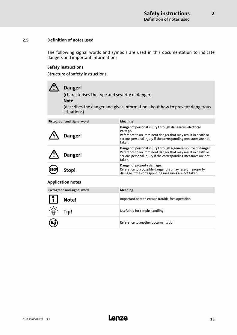
2.5 Definition of notes used
The following signal words and symbols are used in this documentation to indicatedangers and important information:
Safety instructions
Structure of safety instructions:
Danger!(characterises the type and severity of danger)Note(describes the danger and gives information about how to prevent dangeroussituations)
Pictograph and signal word Meaning
Danger!
Danger of personal injury through dangerous electricalvoltage.Reference to an imminent danger that may result in death orserious personal injury if the correspondingmeasures are nottaken.
Danger!Danger of personal injury through a general source of danger.Reference to an imminent danger that may result in death orserious personal injury if the correspondingmeasures are nottaken.
Stop!Danger of property damage.Reference to a possible danger that may result in propertydamage if the correspondingmeasures are not taken.
Application notes
Pictograph and signal word Meaning
Note! Important note to ensure trouble-free operation
Tip! Useful tip for simple handling
Reference to another documentation
Technical dataFeatures
3
14 GHB 13.0002-EN 3.1
3 Technical data
3.1 Features
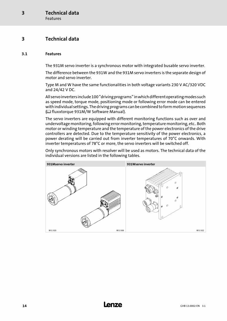
The 931M servo inverter is a synchronous motor with integrated busable servo inverter.
The difference between the 931Wand the 931M servo inverters is the separate design ofmotor and servo inverter.
Type M andW have the same functionalities in both voltage variants 230 V AC/320 VDCand 24/42 V DC.
Allservoinverters include100”drivingprograms”inwhichdifferentoperatingmodessuchas speed mode, torque mode, positioning mode or following error mode can be enteredwith individualsettings. Thedrivingprogramscanbecombinedtoformmotionsequences( fluxxtorque 931M/W Software Manual).
The servo inverters are equipped with different monitoring functions such as over andundervoltagemonitoring, followingerrormonitoring, temperaturemonitoring, etc.. Bothmotor or winding temperature and the temperature of the power electronics of the drivecontrollers are detected. Due to the temperature sensitivity of the power electronics, apower derating will be carried out from inverter temperatures of 70°C onwards. Withinverter temperatures of 78°C or more, the servo inverters will be switched off.
Only synchronous motors with resolver will be used as motors. The technical data of theindividual versions are listed in the following tables.
931Mservo inverter 931Wservo inverter
M13.1020 M13.1006 M13.1022
Technical dataDesign
3
15GHB 13.0002-EN 3.1
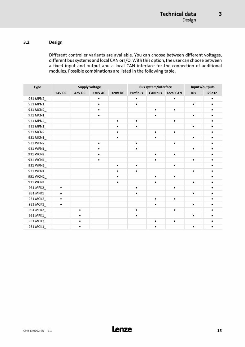
3.2 Design
Different controller variants are available. You can choose between different voltages,different bus systems and local CANor I/O.With this option, the user can choosebetweena fixed input and output and a local CAN interface for the connection of additionalmodules. Possible combinations are listed in the following table:
Type Supply voltage Bus system/interface Inputs/outputs
24V DC 42V DC 230V AC 320V DC Profibus CAN bus Local CAN IOs RS232
931MPN2_ • • • •931MPN1_ • • • •931MCN2_ • • • •931MCN1_ • • • •931MPN2_ • • • •931MPN1_ • • • •931MCN2_ • • • •931MCN1_ • • • •931WPN2_ • • • •931WPN1_ • • • •931WCN2_ • • • •931WCN1_ • • • •931WPN2_ • • • •931WPN1_ • • • •931WCN2_ • • • •931WCN1_ • • • •931MPK2_ • • • •931MPK1_ • • • •931MCK2_ • • • •931MCK1_ • • • •931MPK2_ • • • •931MPK1_ • • • •931MCK2_ • • • •931MCK1_ • • • •
Technical dataRated dataGeneral data and operating conditions
3
16 GHB 13.0002-EN 3.1
3.3 Rated data
3.3.1 General data and operating conditions
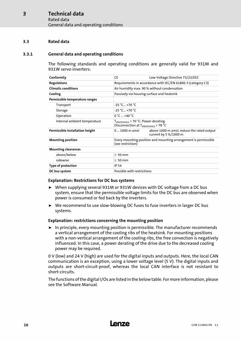
The following standards and operating conditions are generally valid for 931M and931W servo inverters:
Conformity CE Low-Voltage Directive 73/23/EEC
Regulations Requirements in accordance with IEC/EN 61800-3 (category C3)
Climatic conditions Air humidity max. 90 %without condensation
Cooling Passively via housing surface and heatsink
Permissible temperature ranges
Transport -25 °C... +70 °C
Storage -25 °C... +70 °C
Operation 0 °C ... +40 °C
Internal ambient temperature Telectronics > 70 °C: Power deratingDisconnection at Telectronics > 78 °C
Permissible installation height 0 ... 1000m amsl above 1000m amsl, reduce the rated outputcurrent by 5 %/1000m
Mounting position Every mounting position and mounting arrangement is permissible(see restriction)
Mounting clearances
above/below ≥ 50mm
sidewise ≥ 50mm
Type of protection IP 54
DC bus system Possible with restrictions
Explanation: Restrictions for DC bus systems
ƒ When supplying several 931M or 931W devices with DC voltage from a DC bussystem, ensure that the permissible voltage limits for the DC bus are observed whenpower is consumed or fed back by the inverters.
ƒ We recommend to use slow-blowing DC fuses to fuse inverters in larger DC bussystems.
Explanation: restrictions concerning the mounting position
ƒ In principle, every mounting position is permissible. The manufacturer recommendsa vertical arrangement of the cooling ribs of the heatsink. For mounting positionswith a non-vertical arrangement of the cooling ribs, the free convection is negativelyinfluenced. In this case, a power derating of the drive due to the decreased coolingpower may be required.
0 V (low) and 24 V (high) are used for the digital inputs and outputs. Here, the local CANcommunication is an exception, using a lower voltage level (5 V). The digital inputs andoutputs are short-circuit-proof, whereas the local CAN interface is not resistant toshort-circuits.
The functionsof thedigital I/Os are listed in thebelow table. Formore information, pleasesee the Software Manual.
Technical dataRated data
Internal brake resistor
3
17GHB 13.0002-EN 3.1
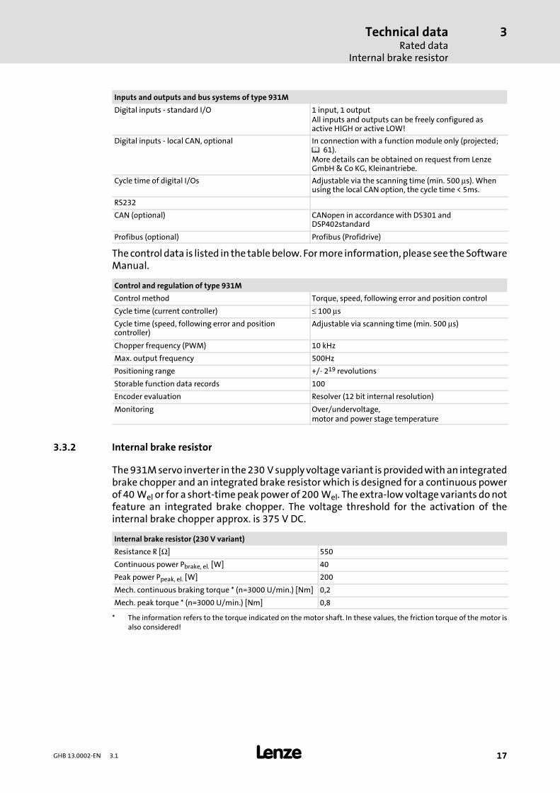
Inputs and outputs and bus systems of type 931M
Digital inputs - standard I/O 1 input, 1 outputAll inputs and outputs can be freely configured asactive HIGH or active LOW!
Digital inputs - local CAN, optional In connection with a function module only (projected; 61).More details can be obtained on request from LenzeGmbH& Co KG, Kleinantriebe.
Cycle time of digital I/Os Adjustable via the scanning time (min. 500 μs). Whenusing the local CAN option, the cycle time < 5ms.
RS232
CAN (optional) CANopen in accordance with DS301 andDSP402standard
Profibus (optional) Profibus (Profidrive)
The control data is listed in the tablebelow. Formore information, please see theSoftwareManual.
Control and regulation of type 931M
Control method Torque, speed, following error and position control
Cycle time (current controller) ≤ 100 μsCycle time (speed, following error and positioncontroller)
Adjustable via scanning time (min. 500 μs)
Chopper frequency (PWM) 10 kHz
Max. output frequency 500Hz
Positioning range +/- 219 revolutions
Storable function data records 100
Encoder evaluation Resolver (12 bit internal resolution)
Monitoring Over/undervoltage,motor and power stage temperature
3.3.2 Internal brake resistor
The931Mservo inverter in the230 Vsupplyvoltagevariant isprovidedwithan integratedbrake chopper and an integrated brake resistorwhich is designed for a continuous powerof 40 Wel or for a short-timepeakpower of 200Wel. The extra-lowvoltage variants donotfeature an integrated brake chopper. The voltage threshold for the activation of theinternal brake chopper approx. is 375 V DC.
Internal brake resistor (230 V variant)
Resistance R [Ω] 550
Continuous power Pbrake, el. [W] 40
Peak power Ppeak, el. [W] 200
Mech. continuous braking torque * (n=3000 U/min.) [Nm] 0,2
Mech. peak torque * (n=3000 U/min.) [Nm] 0,8
* The information refers to the torque indicated on themotor shaft. In these values, the friction torque of the motor isalso considered!
Technical dataRated dataRated data of the extra-low voltage version (24 or 42 V DC)
3
18 GHB 13.0002-EN 3.1
3.3.3 Rated data of the extra-low voltage version (24 or 42 V DC)
Theextra-lowvoltageversionofthedriveshasbeendesignedforoperationon24/42 VDC.For a simple servo inverter operation, a 24Vor 42V supply is sufficient.With anadditional24Vauxiliary supply, the control continues tobe supplied if anerror occursand the supplyvoltage is disconnected. Important data (rotor position, information on faults, etc.) willthus continue to be recorded and transferred to the control.
Note!The residual ripple component of the supply voltage must be under 5%.
The24 Vauxiliarysupply isalsorequired if thedigital interface (digital I/O)or the localCANinterface is used.
3.3.4 Rated data of the low-voltage version (230 V AC / 320 V DC)
Inverterswith230 V ACmainssupplyhaveanadditional24 Vauxiliary supply. Thecontrolis also supplied by themains voltage.With an additional 24V auxiliary supply, the controlcontinues to be supplied if an error occurs and the supply voltage is disconnected.Important data (rotor position, information on faults, etc.) will thus continue to berecorded and transferred to the control.
The24 Vauxiliarysupply isalsorequired if thedigital interface (digital I/O)or the localCANinterface is used.
Technical dataRated data
Rated data of the drive systems
3
19GHB 13.0002-EN 3.1
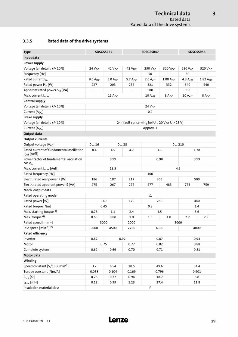
3.3.5 Rated data of the drive systems
Type SDSGSSR35 SDSGSSR47 SDSGSSR56
Input data
Power supply
Voltage (all details +/- 10%) 24 VDC 42 VDC 42 VDC 230 VAC 320 VDC 230 VAC 320 VDCFrequency [Hz] --- --- --- 50 --- 50 ---
Rated current Iin 9.6 ADC 5.0 ADC 5.7 ADC 2.6 Aeff 1.08 ADC 4.3 Aeff 1.82 ADCRated power Pin [W] 227 203 237 321 332 540 540
Apparent rated power Sin [VA] --- --- --- 580 --- 980 ---
Max. current Imax. 15 ADC 10 Aeff 8 ADC 10 Aeff 8 ADCControl supply
Voltage (all details +/- 10%) 24 VDCCurrent [ADC] 0.2
Brake supply
Voltage (all details +/- 10%) 24 ( fault concerning bei U < 20 V or U > 28 V)
Current [ADC] Approx. 1
Output data
Output currents
Output voltage [VAC] 0 ... 16 0 ... 28 0 ... 210
Rated current of fundamental oscillationIOut [Aeff]
8.4 4.5 4.7 1.1 1.78
Power factor of fundamental oscillationcos ϕ1
0.99 0.98 0.99
Max. current Imax [Aeff] 13.5 4.5
Rated frequency [Hz] 100
Electr. rated real power P [W] 186 187 217 305 500
Electr. rated apparent power S [VA] 275 267 277 477 483 773 759
Mech. output data
Rated operatingmode s1
Rated power [W] 140 170 250 440
Rated torque [Nm] 0.45 0.8 1.4
Max. starting torque 3) 0.78 1.1 2.4 3.5 3.6
Max. torque 4) 0.65 0.80 1.0 1.5 1.8 2.7 2.8
Rated speed [min-1] 3000 2000 3000
Idle speed [min-1] 2) 5000 4500 2700 4300 4000
Rated efficiency
Inverter 0.82 0.92 0.87 0.93
Motor 0.75 0.77 0.82 0.88
Complete system 0.62 0.69 0.70 0.71 0.81
Motor data
Winding
Speed constant [V/1000min-1] 3.7 6.54 10.5 49.6 54.4
Torque constant [Nm/A] 0.058 0.104 0.169 0.796 0.901
RUV [Ω] 0.26 0.77 0.94 18.7 6.8
Lline [mH] 0.18 0.59 1.23 27.4 11.8
Insulation material class F
Technical dataRated dataRated data of the drive systems
3
20 GHB 13.0002-EN 3.1
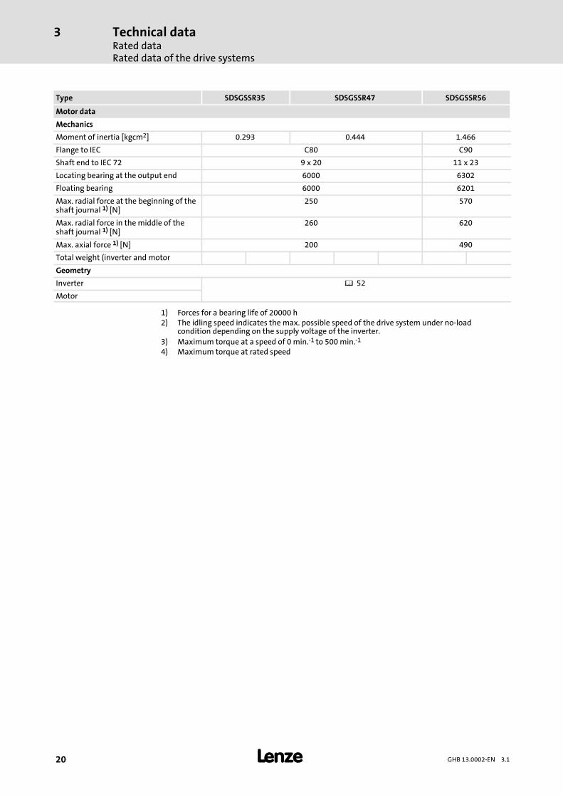
SDSGSSR56SDSGSSR47SDSGSSR35Type
Motor data
Mechanics
Moment of inertia [kgcm2] 0.293 0.444 1.466
Flange to IEC C80 C90
Shaft end to IEC 72 9 x 20 11 x 23
Locating bearing at the output end 6000 6302
Floating bearing 6000 6201
Max. radial force at the beginning of theshaft journal 1) [N]
250 570
Max. radial force in the middle of theshaft journal 1) [N]
260 620
Max. axial force 1) [N] 200 490
Total weight (inverter and motor
Geometry
Inverter 52
Motor
1) Forces for a bearing life of 20000 h2) The idling speed indicates the max. possible speed of the drive system under no-load
condition depending on the supply voltage of the inverter.3) Maximum torque at a speed of 0 min.-1 to 500min.-1
4) Maximum torque at rated speed
Technical dataRated data
Rated data for S3 operation/overload capacity
3
21GHB 13.0002-EN 3.1
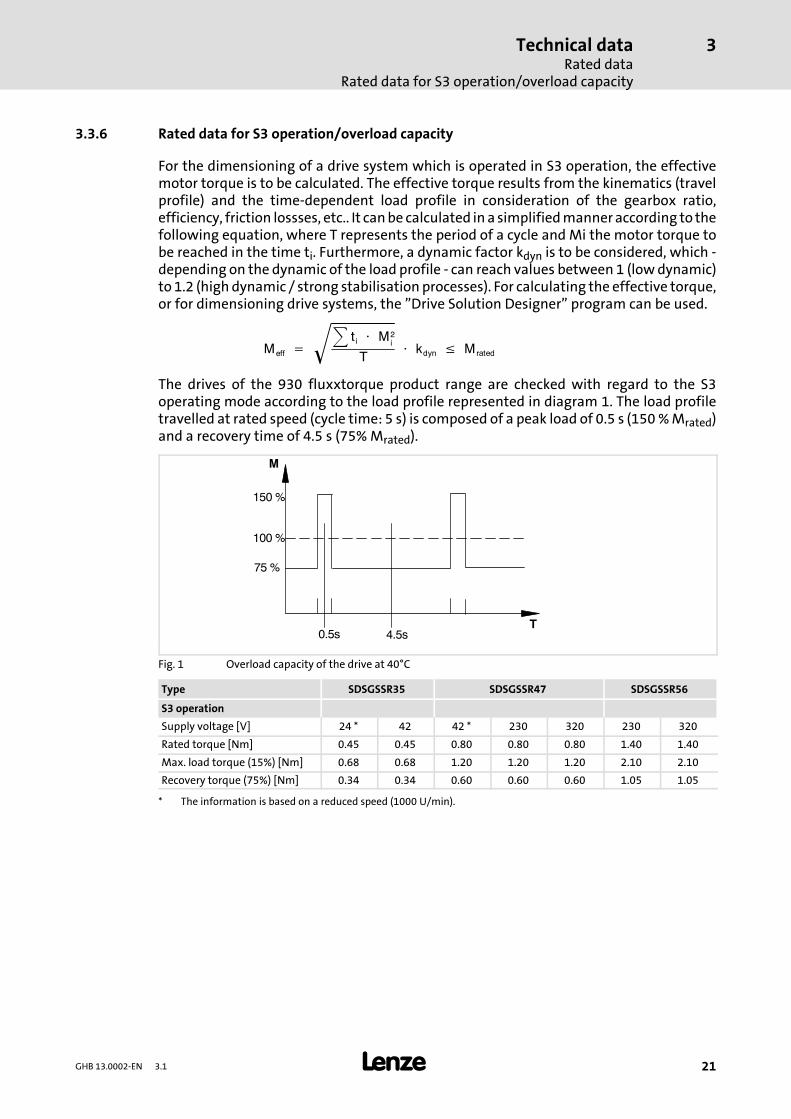
3.3.6 Rated data for S3 operation/overload capacity
For the dimensioning of a drive system which is operated in S3 operation, the effectivemotor torque is to be calculated. The effective torque results from the kinematics (travelprofile) and the time-dependent load profile in consideration of the gearbox ratio,efficiency, friction lossses, etc.. It canbe calculated in a simplifiedmanneraccording to thefollowing equation, where T represents the period of a cycle and Mi the motor torque tobe reached in the time ti. Furthermore, a dynamic factor kdyn is to be considered, which -depending on the dynamic of the load profile - can reach values between 1 (lowdynamic)to 1.2 (high dynamic / strong stabilisation processes). For calculating the effective torque,or for dimensioning drive systems, the ”Drive Solution Designer” program can be used.
Meff = t i ⋅ M2
i
T ⋅ kdyn ≤ Mrated
The drives of the 930 fluxxtorque product range are checked with regard to the S3operating mode according to the load profile represented in diagram 1. The load profiletravelled at rated speed (cycle time: 5 s) is composed of a peak load of 0.5 s (150%Mrated)and a recovery time of 4.5 s (75%Mrated).
0.5s 4.5sT
M
100 %
75 %
150 %
Fig. 1 Overload capacity of the drive at 40°C
Type SDSGSSR35 SDSGSSR47 SDSGSSR56
S3 operation
Supply voltage [V] 24 * 42 42 * 230 320 230 320
Rated torque [Nm] 0.45 0.45 0.80 0.80 0.80 1.40 1.40
Max. load torque (15%) [Nm] 0.68 0.68 1.20 1.20 1.20 2.10 2.10
Recovery torque (75%) [Nm] 0.34 0.34 0.60 0.60 0.60 1.05 1.05
* The information is based on a reduced speed (1000 U/min).
Technical dataConnection cablesSystem cable for 931M/W voltage supply
3
22 GHB 13.0002-EN 3.1
3.4 Connection cables
3.4.1 System cable for 931M/W voltage supply
In general, the cable length for the connection, motor and resolver cables should not belonger than 5m; in exceptional cases, however, themaximumcable lengthmay be 10 m.
Different plugs are used to ensure that extra-lowvoltage and low-voltage devices cannotbe connected to incorrect voltage potentials.
For more information on the connection cables, please see chapter 10.
3.4.1.1 System cable for 931M 24 V or 42 V voltage supply
Motor connection side Length[m]
Voltage supply end Designation
Binder M16/0.75 socket; 8-pole3
without plug491 629
5 491 725
3.4.1.2 System cable for 931M/W 230 V or 320 V voltage supply
Motor connection side Length[m]
Voltage supply end Designation
M23 socket; 8-pole3
without plug491 726
5 491 727
3.4.1.3 System cable for motor - 931W servo inverter
Inverter end X3 Length[m] Motor connection side Designation
M23 socket; 4+4-pole 2.5 M26 plug; 6-poleConnection
motor - servo inverter13009633
3.4.1.4 System cable for servo inverter feedback
Inverter end X7 Length[m] Motor connection side Designation
M23 socket; 12-pole 2.5 M23 plug; 12-pole 13009634
Technical dataConnection cables
Connection cables for bus systems
3
23GHB 13.0002-EN 3.1
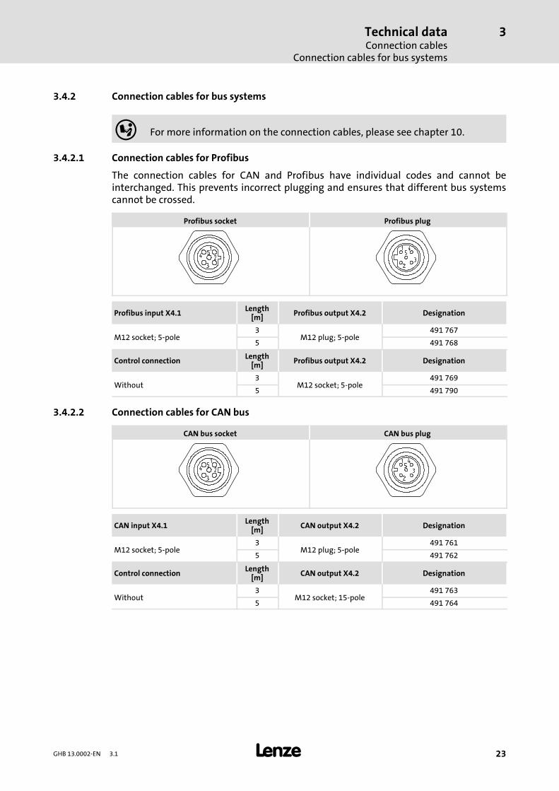
3.4.2 Connection cables for bus systems
For more information on the connection cables, please see chapter 10.
3.4.2.1 Connection cables for Profibus
The connection cables for CAN and Profibus have individual codes and cannot beinterchanged. This prevents incorrect plugging and ensures that different bus systemscannot be crossed.
Profibus socket Profibus plug
Profibus input X4.1 Length[m] Profibus output X4.2 Designation
M12 socket; 5-pole3
M12 plug; 5-pole491 767
5 491 768
Control connection Length[m] Profibus output X4.2 Designation
Without3
M12 socket; 5-pole491 769
5 491 790
3.4.2.2 Connection cables for CAN bus
CAN bus socket CAN bus plug
CAN input X4.1 Length[m] CAN output X4.2 Designation
M12 socket; 5-pole3
M12 plug; 5-pole491 761
5 491 762
Control connection Length[m] CAN output X4.2 Designation
Without3
M12 socket; 15-pole491 763
5 491 764
Technical dataConnection cablesConnecting cables
3
24 GHB 13.0002-EN 3.1
3.4.3 Connecting cables
3.4.3.1 Connecting cables for RS232
Controller end X1 Length[m] PC end Designation
M8 socket; 3-pole 3 Sub D; 9-pole 491 791
3.4.3.2 Connecting cable for local CAN and I/O
Controller end X5 Length[m]
Additional module end Designation
M8 socket; 4-pole 3 ----- 491 996

Mechanical installationImportant notes
4
25GHB 13.0002-EN 3.1
4 Mechanical installation
Stop!Ensure that the 931M/W servo inverters are securely connected using thescrew connections provided and prevent excessive mechanical stress on thescrew connections.
4.1 Important notes
ƒ For polluted cooling air (dust, lints, greases, aggressive gases):
– Implement adequate counter measures, e. g. separate routing of ait flow, regularcleaning, etc.
ƒ Mounting clearances!
– Observe unobstructed influx of the cooling air and emission of the exhaust air!
– Observe a free space of 50 mm above and below as well as to the sides.
– In case of high load and bad heat dissipation, the controller lowers the drivepower, or possibly switches off.
ƒ Do not exceed the range of the ambient operation temperature.
ƒ For permanent vibrations or vibrancies:
– Check the use of vibration dampers.
Mechanical installationMechanical installation of 931M
4
26 GHB 13.0002-EN 3.1
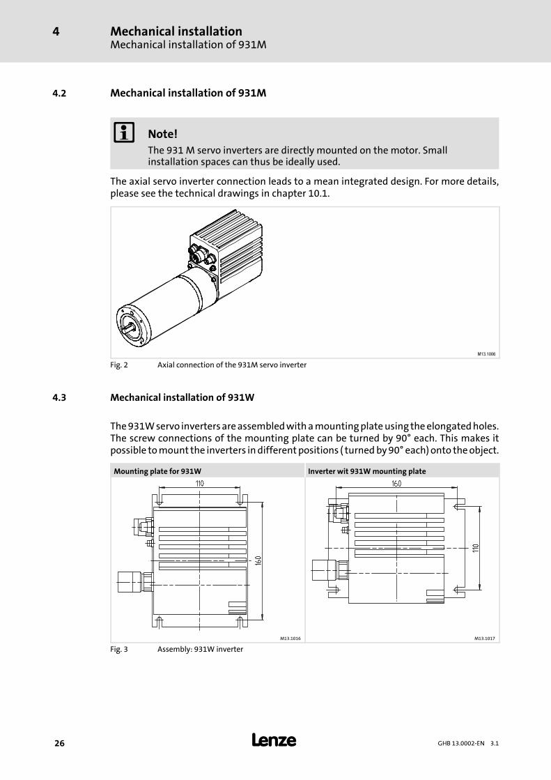
4.2 Mechanical installation of 931M
Note!The 931 M servo inverters are directly mounted on the motor. Smallinstallation spaces can thus be ideally used.
The axial servo inverter connection leads to a mean integrated design. For more details,please see the technical drawings in chapter 10.1.
M13.1006
Fig. 2 Axial connection of the 931M servo inverter
4.3 Mechanical installation of 931W
The931Wservo invertersareassembledwithamountingplateusing theelongatedholes.The screw connections of the mounting plate can be turned by 90° each. This makes itpossible tomount the inverters indifferentpositions ( turnedby90° each)onto theobject.
Mounting plate for 931W Inverter wit 931Wmounting plate
M13.1016 M13.1017
Fig. 3 Assembly: 931W inverter
Mechanical installationMounting plate for 931W
4
27GHB 13.0002-EN 3.1
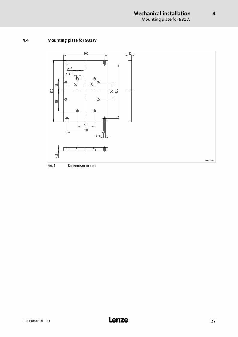
4.4 Mounting plate for 931W
M13.1003
Fig. 4 Dimensions in mm
Electrical installationImportant notes
5
28 GHB 13.0002-EN 3.1
5 Electrical installation
5.1 Important notes
Stop!The drive controller contains electrostatically sensitive components.The personnel must be free of electrostatic charge prior to assembly andservice operations.
Danger!ƒ The connection of all pluggable terminals has to be effected in adeenergised state.
ƒ Connecting and disconnecting the voltage supply (X2) due to the chargingprocesses of the intermediate circuit capacitor may cause traces of burningon the wrap connection, and may result in a destruction of the internalelectronic circuit.
ƒ A false polarity of the DC supply can bring about the destruction of thedrive. Before switching the drive on, ensure that the polarity of theDC supply is correct.
Note!For trouble-free operation, the following conditions are required:ƒ An installation according to EMC.ƒ The shield of the motor cable has to be connected to PE potential asextensively as possible to prevent effects due to interference.
ƒ The resolver cable, encoder cable, and the motor cable may have a length of10 m at a maximum!
ƒ The feeding power supply units have to be sufficiently dimensioned. Thepower supply units have to be protected against overcurrent by means ofappropriate input fuses.
Electrical installationInstallation according to EMC (installation of a CE-typical drive system)
5
29GHB 13.0002-EN 3.1
5.2 Installation according to EMC (installation of a CE-typical drive system)
Important notes
Theelectromagneticcompatibilityofamachinedependsonthetypeof installationandonthe care that is taken. Special attention should be paid to:
ƒ Assembly
ƒ Shielding
ƒ Grounding
For diverging installations, the conformity to the EMC Directive requires a check of themachine or system regarding the EMC limit values. This, for instance, applies to the use ofunshielded cables.
The compliance of themachine applicationwith the EMCDirective is in the responsibilityof the user.
ƒ If you observe the following measures, you can assume that the machine willoperate without any EMC problems caused by the drive system, and that compliancewith the EMC Directive and the EMC law is achieved.
ƒ If devices which do not comply with the CE requirements concerning noiseimmunity EN 50082-2 are operated close to the controller, these devices may beelectromagnetically disturbed by the controllers.
Shielding
ƒ Connect the shield of the motor cable on the 931W drive controller to the shieldconnection of the drive controller.
ƒ Extensively connect the shield in the terminal box on the motor or on the motorhousing to PE:
– Metal glands at the motor terminal box ensure a connection of the shield and themotor housing.
Earthing
Ground all metallically conductive components (controller, motor filter) using suitablecables connected to a central earthing point (PE bar).
Maintain the minimum cross-sections prescribed in the safety regulations:
ƒ With regard to EMC, however, not the cable cross-section is important, but thesurface of the cable and the contact with a cross-section as large as possible, i.e.large surface.
Electrical installationElectrical connections of 931M, 24 V DC / 42 V DC
5
30 GHB 13.0002-EN 3.1
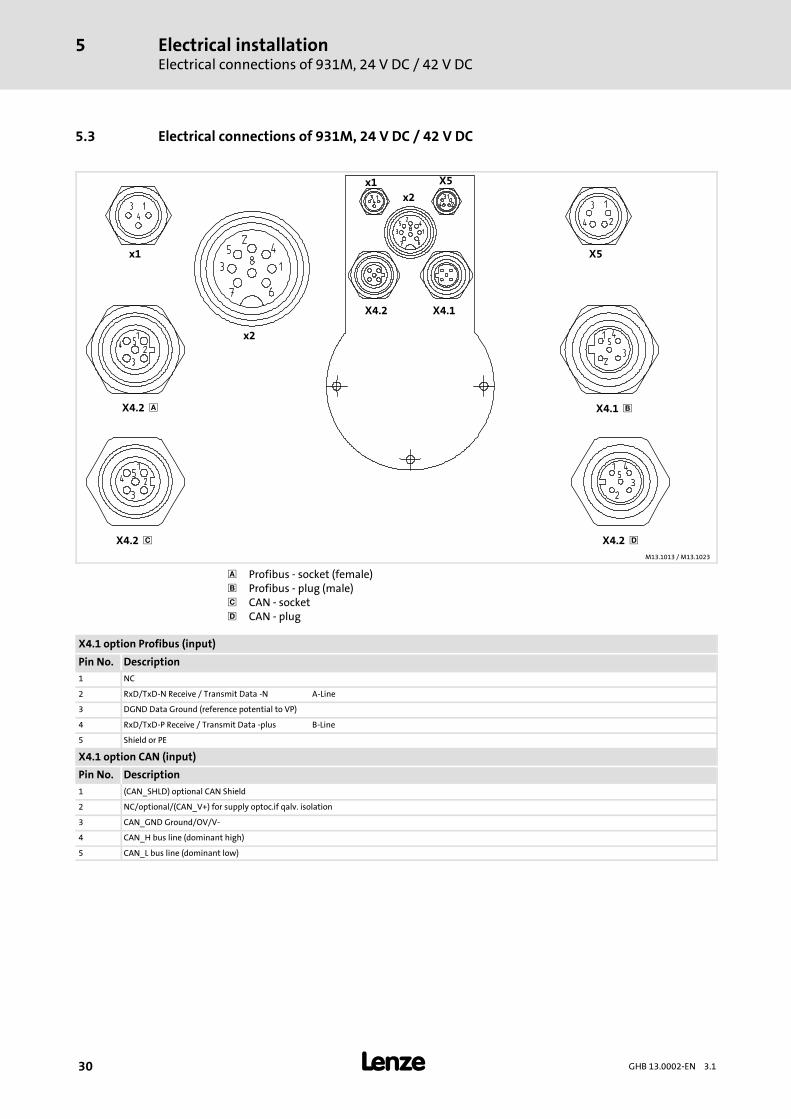
5.3 Electrical connections of 931M, 24 V DC / 42 V DC
x1 X5
x2
X4.2 X4.1
X4.2 X4.1
X5x1x2
X4.2 X4.2 M13.1013 /M13.1023
Profibus - socket (female) Profibus - plug (male) CAN - socket CAN - plug
X4.1 option Profibus (input)
Pin No. Description1 NC
2 RxD/TxD-N Receive / Transmit Data -N A-Line
3 DGND Data Ground (reference potential to VP)
4 RxD/TxD-P Receive / Transmit Data -plus B-Line
5 Shield or PE
X4.1 option CAN (input)
Pin No. Description1 (CAN_SHLD) optional CAN Shield
2 NC/optional/(CAN_V+) for supply optoc.if qalv. isolation
3 CAN_GND Ground/OV/V-
4 CAN_H bus line (dominant high)
5 CAN_L bus line (dominant low)
Electrical installationElectrical connections of 931M, 24 V DC / 42 V DC
5
31GHB 13.0002-EN 3.1
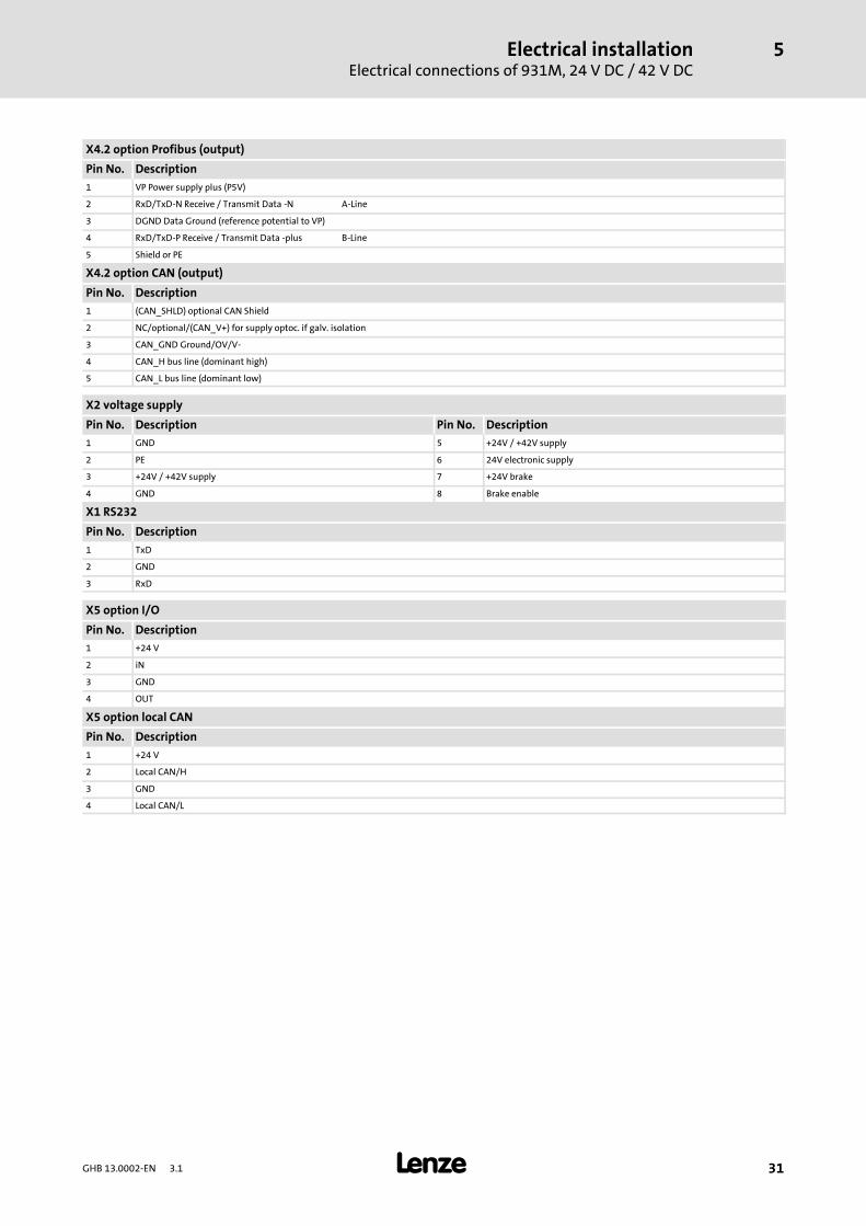
X4.2 option Profibus (output)
Pin No. Description1 VP Power supply plus (P5V)
2 RxD/TxD-N Receive / Transmit Data -N A-Line
3 DGND Data Ground (reference potential to VP)
4 RxD/TxD-P Receive / Transmit Data -plus B-Line
5 Shield or PE
X4.2 option CAN (output)
Pin No. Description1 (CAN_SHLD) optional CAN Shield
2 NC/optional/(CAN_V+) for supply optoc. if galv. isolation
3 CAN_GND Ground/OV/V-
4 CAN_H bus line (dominant high)
5 CAN_L bus line (dominant low)
X2 voltage supply
Pin No. Description Pin No. Description1 GND 5 +24V / +42V supply
2 PE 6 24V electronic supply
3 +24V / +42V supply 7 +24V brake
4 GND 8 Brake enable
X1 RS232
Pin No. Description1 TxD
2 GND
3 RxD
X5 option I/O
Pin No. Description1 +24 V
2 iN
3 GND
4 OUT
X5 option local CAN
Pin No. Description1 +24 V
2 Local CAN/H
3 GND
4 Local CAN/L
Electrical installationElectrical connections of 931M, 230 V AC / 320 V DC
5
32 GHB 13.0002-EN 3.1
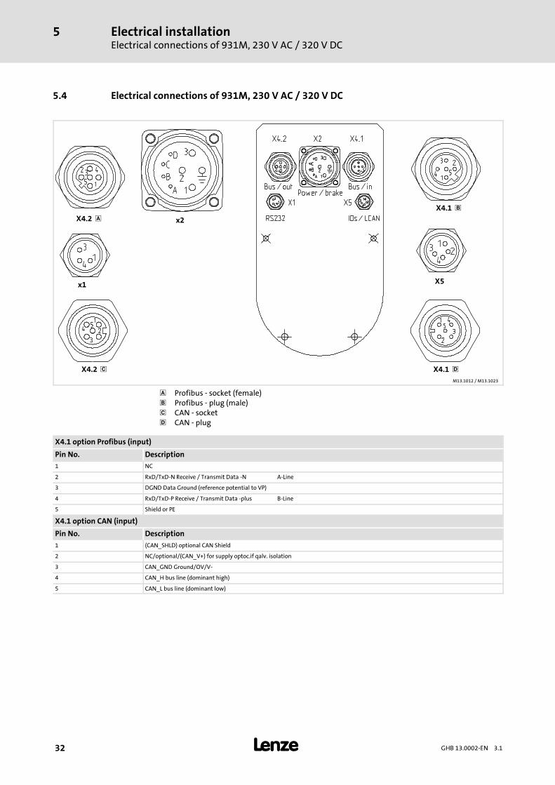
5.4 Electrical connections of 931M, 230 V AC / 320 V DC
x1 X5
x2X4.2
X4.2 X4.1
X4.1
M13.1012 /M13.1023
Profibus - socket (female) Profibus - plug (male) CAN - socket CAN - plug
X4.1 option Profibus (input)
Pin No. Description1 NC
2 RxD/TxD-N Receive / Transmit Data -N A-Line
3 DGND Data Ground (reference potential to VP)
4 RxD/TxD-P Receive / Transmit Data -plus B-Line
5 Shield or PE
X4.1 option CAN (input)
Pin No. Description1 (CAN_SHLD) optional CAN Shield
2 NC/optional/(CAN_V+) for supply optoc.if qalv. isolation
3 CAN_GND Ground/OV/V-
4 CAN_H bus line (dominant high)
5 CAN_L bus line (dominant low)
Electrical installationElectrical connections of 931M, 230 V AC / 320 V DC
5
33GHB 13.0002-EN 3.1
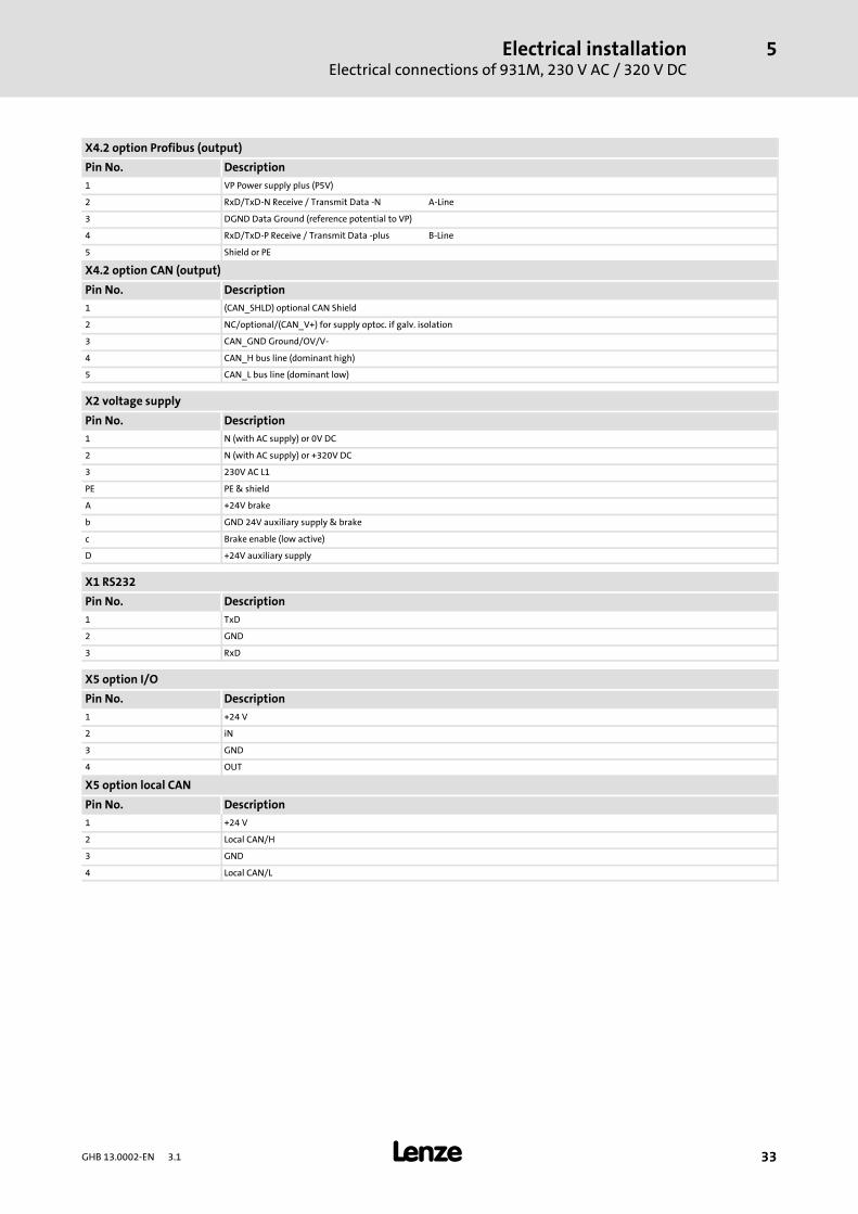
X4.2 option Profibus (output)
Pin No. Description1 VP Power supply plus (P5V)
2 RxD/TxD-N Receive / Transmit Data -N A-Line
3 DGND Data Ground (reference potential to VP)
4 RxD/TxD-P Receive / Transmit Data -plus B-Line
5 Shield or PE
X4.2 option CAN (output)
Pin No. Description1 (CAN_SHLD) optional CAN Shield
2 NC/optional/(CAN_V+) for supply optoc. if galv. isolation
3 CAN_GND Ground/OV/V-
4 CAN_H bus line (dominant high)
5 CAN_L bus line (dominant low)
X2 voltage supply
Pin No. Description1 N (with AC supply) or 0V DC
2 N (with AC supply) or +320V DC
3 230V AC L1
PE PE & shield
A +24V brake
b GND 24V auxiliary supply & brake
c Brake enable (low active)
D +24V auxiliary supply
X1 RS232
Pin No. Description1 TxD
2 GND
3 RxD
X5 option I/O
Pin No. Description1 +24 V
2 iN
3 GND
4 OUT
X5 option local CAN
Pin No. Description1 +24 V
2 Local CAN/H
3 GND
4 Local CAN/L
Electrical installationElectrical connections of 931W, 230V AC / 320V DC
5
34 GHB 13.0002-EN 3.1
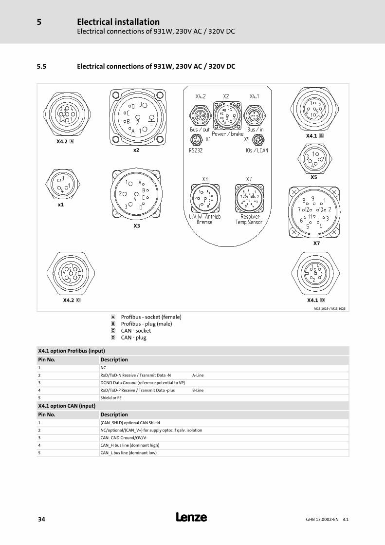
5.5 Electrical connections of 931W, 230V AC / 320V DC
x1
X5
x2
X3
X7
X4.2 X4.1
X4.2 X4.1
M13.1019 /M13.1023
Profibus - socket (female) Profibus - plug (male) CAN - socket CAN - plug
X4.1 option Profibus (input)
Pin No. Description1 NC
2 RxD/TxD-N Receive / Transmit Data -N A-Line
3 DGND Data Ground (reference potential to VP)
4 RxD/TxD-P Receive / Transmit Data -plus B-Line
5 Shield or PE
X4.1 option CAN (input)
Pin No. Description1 (CAN_SHLD) optional CAN Shield
2 NC/optional/(CAN_V+) for supply optoc.if qalv. isolation
3 CAN_GND Ground/OV/V-
4 CAN_H bus line (dominant high)
5 CAN_L bus line (dominant low)
Electrical installationElectrical connections of 931W, 230V AC / 320V DC
5
35GHB 13.0002-EN 3.1
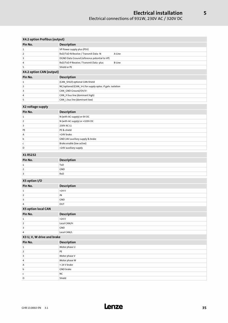
X4.2 option Profibus (output)
Pin No. Description1 VP Power supply plus (P5V)
2 RxD/TxD-N Receive / Transmit Data -N A-Line
3 DGND Data Ground (reference potential to VP)
4 RxD/TxD-P Receive / Transmit Data -plus B-Line
5 Shield or PE
X4.2 option CAN (output)
Pin No. Description1 (CAN_SHLD) optional CAN Shield
2 NC/optional/(CAN_V+) for supply optoc. if galv. isolation
3 CAN_GND Ground/OV/V-
4 CAN_H bus line (dominant high)
5 CAN_L bus line (dominant low)
X2 voltage supply
Pin No. Description1 N (with AC supply) or 0V DC
2 N (with AC supply) or +320V DC
3 230V AC L1
PE PE & shield
A +24V brake
b GND 24V auxiliary supply & brake
c Brake enable (low active)
D +24V auxiliary supply
X1 RS232
Pin No. Description1 TxD
2 GND
3 RxD
X5 option I/O
Pin No. Description1 +24 V
2 iN
3 GND
4 OUT
X5 option local CAN
Pin No. Description1 +24 V
2 Local CAN/H
3 GND
4 Local CAN/L
X3 U, V, W drive and brake
Pin No. Description1 Motor phase U
2 PE
3 Motor phase V
4 Motor phaseW
A + 24 V brake
b GND brake
c NC
D Shield
Electrical installationElectrical connections of 931W, 230V AC / 320V DC
5
36 GHB 13.0002-EN 3.1
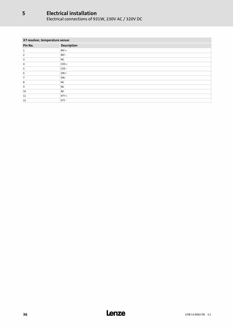
X7 resolver, temperature sensor
Pin No. Description1 REF +
2 REF -
3 NC
4 COS +
5 COS -
6 SIN +
7 SIN -
8 NC
9 NC
10 NC
11 KTY +
12 KTY -
CommissioningBefore switching on
Voltage supply connection
6
37GHB 13.0002-EN 3.1
6 Commissioning
6.1 Before switching on
Stop!Avoid injury to persons and damage to material assets during commissioning!ƒ Necessarily observe the switch-on sequence.ƒ During the resolver adjustment, the drive has to be able to rotate freelywithout load!
Tip!For faults during commissioning, see chapter Troubleshooting and faultelimination. ( 45)
Checking of electrical connections
Before the first commissioning, before commissioning after longer downtimes, check:
ƒ the electrical connection with regard to completeness, short circuit and earth fault.
ƒ All plugs on the controller must be securely connected using the screw and plugconnections provided.
ƒ The screw connections on the motor must be securely connected.
ƒ Carefully check the connections to the supply system and ensure that thecurrent-carrying connections are correct.
ƒ 24 V and 42 V controllers require correspondingly high currents to reach theirmaximum performance.
6.1.1 Voltage supply connection
ƒ Ensure correct pole connections (extra-low voltage or mains voltage) for feeding thevoltage supply (extra-low voltage)!
ƒ Ensure that auxiliary supply (24 V for control) and supply voltage (24 V or 42 VDC-bus supply) are separately connected. When the supply is mixed up, the servoinverter may be destroyed.
6.1.2 Motor connection
ƒ For trouble-free operation, we recommend to use Lenze standard cables.
ƒ Ensure a proper shielding of the motor and feedback cable to avoid interferences.
CommissioningBefore switching onExternal inputs and outputs / connection with local CAN devices
6
38 GHB 13.0002-EN 3.1
6.1.3 External inputs and outputs / connection with local CAN devices
ƒ For trouble-free operation, ensure that the additional modules are correctlyconnected.
ƒ The connection cables for switches must be shielded.
ƒ In general, the cables should not be longer than 5m. In exceptional cases, themaximum cable lengthmay be 10m.
6.1.4 Bus cable connections
ƒ Use Lenze standard cables (see chapter 5).
ƒ Bus cables should always be shielded.
ƒ Check the screw connections of the bus cables.
6.1.5 Connection of the connecting cable between PC and servo inverter
Servo inverter and PC are connected via an RS 232 interface using the 9-pole Sub-Dinterface of the PC and the 3-pole M8 connection of the servo inverter.
ƒ Securely connect the connecting cable with the PC and the servo inverter.
6.1.6 Covers for the power connections
ƒ Put on and fix cover(s).
Application examplesPreconditions
7
39GHB 13.0002-EN 3.1
7 Application example
7.1 Preconditions
Stop!Before the first commissioning, the motor of the drive system or theintegrated servo inverter should be placed on a level surface. The motor shaftshould be freely movable and protected against contact. Ensure that the key issecured (if accessible).
Install the ”fluxx” software on your PC. For this, copy the program provided to yourcomputer and start it with a double-click from the directory towhich you have copied theprogram.
7.2 General information
The ”fluxx” user software has been developed for the commissioning, test purposes andeasy monitoring of the drive. Use the software to easily start the servo inverter.
The ”fluxx” functions are explained in the ”fluxxtorque servo inverter”Software Manual.
Note!Operation of the software requires the Microsoft operating systemWindowsNT 4.0, Windows 95/98, Windows 2000 or Windows XP.
7.3 Menu pages
For this example, you only need the menu pages Setup, Status and Driving program. Thefollowing sections describe the functions of the individual menu pages.
Application examplesMenu pagesSetup menu page
7
40 GHB 13.0002-EN 3.1
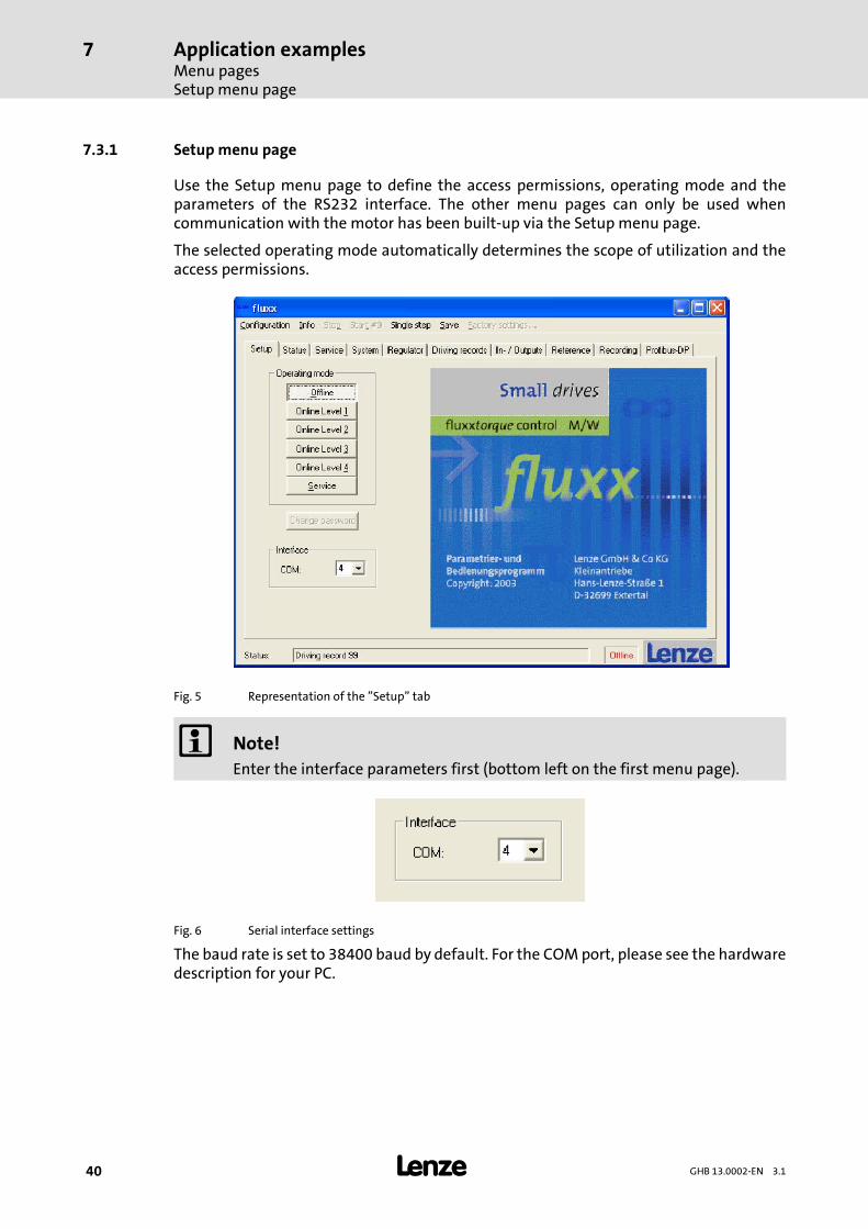
7.3.1 Setup menu page
Use the Setup menu page to define the access permissions, operating mode and theparameters of the RS232 interface. The other menu pages can only be used whencommunication with the motor has been built-up via the Setup menu page.
The selected operating mode automatically determines the scope of utilization and theaccess permissions.
Fig. 5 Representation of the ”Setup” tab
Note!Enter the interface parameters first (bottom left on the first menu page).
Fig. 6 Serial interface settings
The baud rate is set to 38400 baud by default. For the COMport, please see the hardwaredescription for your PC.
Application examplesMenu pages
Setup menu page
7
41GHB 13.0002-EN 3.1
Note!In the default setting, the individual operating levels are notpassword-protected. If you want to use a password, please consider that theservo inverter must be returned to Lenze for password deactivation when thepassword gets lost!
In this example, log in under ”Online Level 3”. In this operating level, you can select speedand torque for a trial operation and start the driving program. You will be asked for apassword. Do not enter anything and confirm with ”OK”.
If the power supply and the PC have been properly connected, the individual drivingprogramswill bewritten to the PCwhen changing from”Offline” to ”Online Level 3”. Thiscanbeseen inthestatusbarwheretheprogramcountsfromdrivingprogram0to99.Now,you have an online connection with the drive.
On the lower edge of the operating program on the left next to the Lenze icon, theconnection status is alsodisplayed. If youhaveestablished theconnection tothedrive, themessage ”Online” is displayed there in green font. If you are not able to establish aconnection, an error is indicated.
Application examplesMenu pagesStatus menu page
7
42 GHB 13.0002-EN 3.1
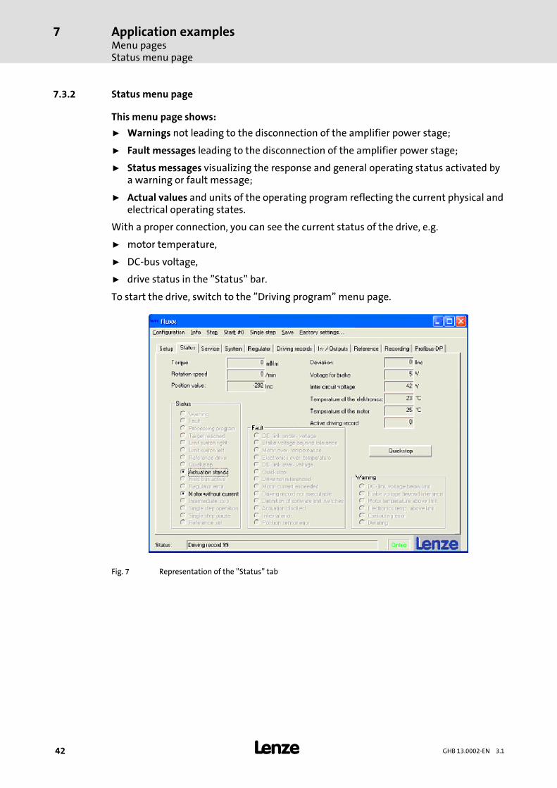
7.3.2 Status menu page
This menu page shows:
ƒ Warnings not leading to the disconnection of the amplifier power stage;
ƒ Fault messages leading to the disconnection of the amplifier power stage;
ƒ Status messages visualizing the response and general operating status activated bya warning or fault message;
ƒ Actual values and units of the operating program reflecting the current physical andelectrical operating states.
With a proper connection, you can see the current status of the drive, e.g.
ƒ motor temperature,
ƒ DC-bus voltage,
ƒ drive status in the ”Status” bar.
To start the drive, switch to the ”Driving program” menu page.
Fig. 7 Representation of the ”Status” tab
Application examplesMenu pages
Driving programmenu page
7
43GHB 13.0002-EN 3.1
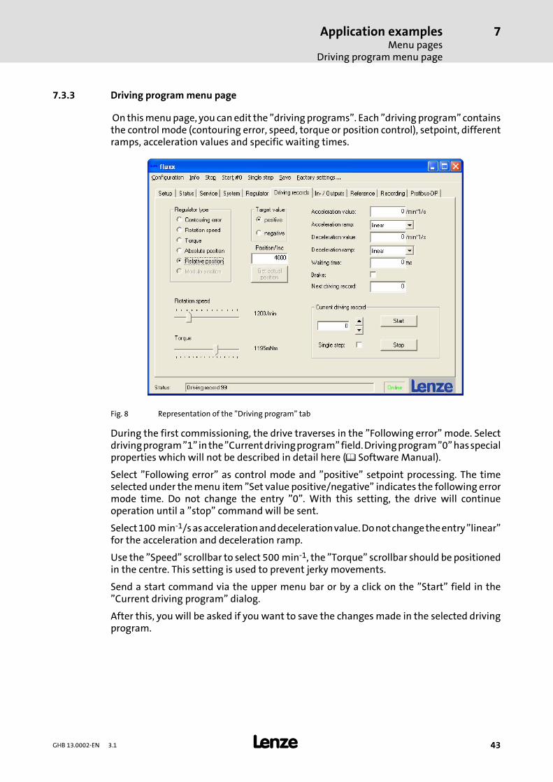
7.3.3 Driving programmenu page
On thismenupage, you canedit the ”drivingprograms”. Each ”driving program” containsthe control mode (contouring error, speed, torque or position control), setpoint, differentramps, acceleration values and specific waiting times.
Fig. 8 Representation of the ”Driving program” tab
During the first commissioning, the drive traverses in the ”Following error” mode. Selectdrivingprogram”1”inthe”Currentdrivingprogram”field.Drivingprogram”0”hasspecialproperties which will not be described in detail here ( Software Manual).
Select ”Following error” as control mode and ”positive” setpoint processing. The timeselected under themenu item ”Set value positive/negative” indicates the following errormode time. Do not change the entry ”0”. With this setting, the drive will continueoperation until a ”stop” command will be sent.
Select100 min-1/sasaccelerationanddecelerationvalue.Donotchangetheentry”linear”for the acceleration and deceleration ramp.
Use the ”Speed” scrollbar to select 500 min-1, the ”Torque” scrollbar should be positionedin the centre. This setting is used to prevent jerky movements.
Send a start command via the upper menu bar or by a click on the ”Start” field in the”Current driving program” dialog.
After this, you will be asked if you want to save the changesmade in the selected drivingprogram.
Application examplesMenu pagesDriving programmenu page
7
44 GHB 13.0002-EN 3.1
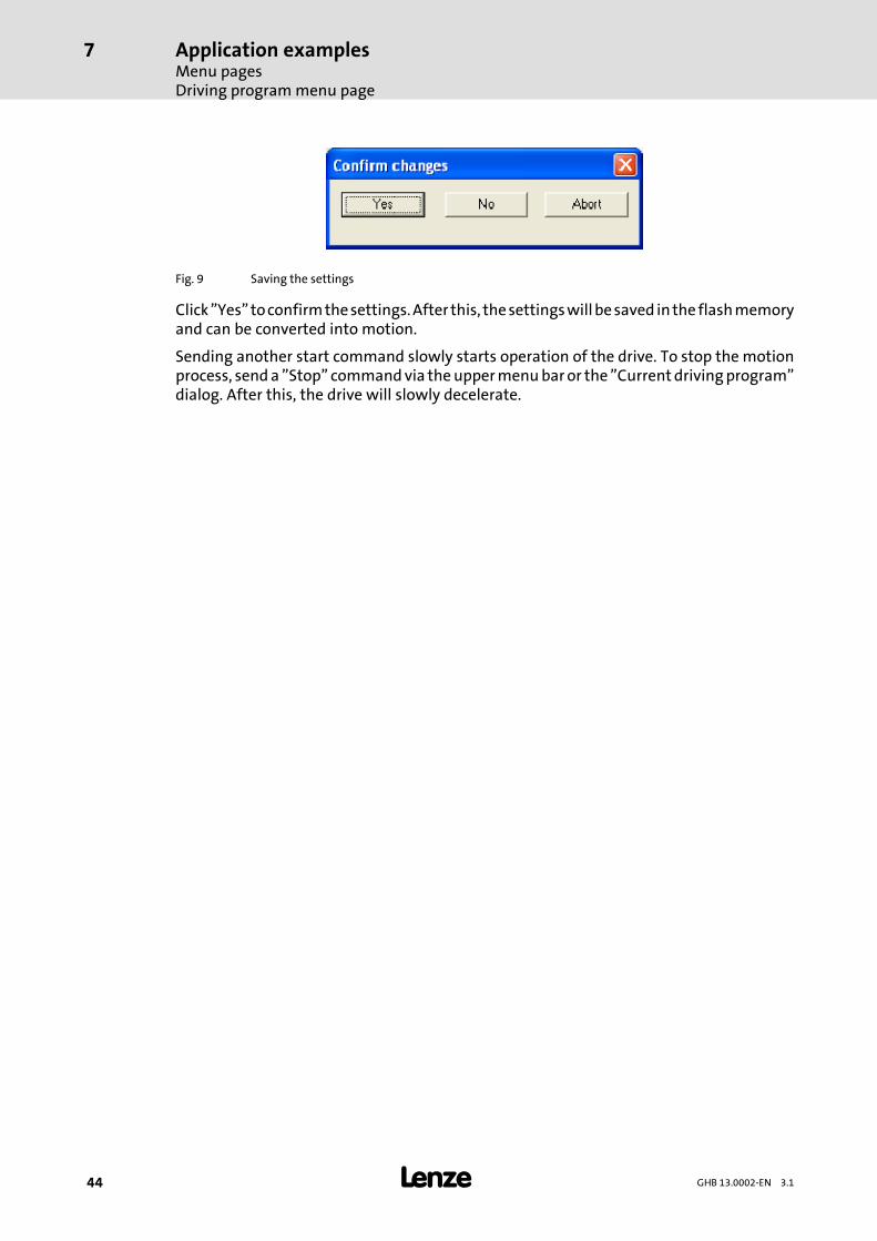
Fig. 9 Saving the settings
Click”Yes”toconfirmthesettings.After this, thesettingswillbesaved inthe flashmemoryand can be converted into motion.
Sending another start command slowly starts operation of the drive. To stop the motionprocess, senda ”Stop” commandvia theuppermenubaror the ”Current drivingprogram”dialog. After this, the drive will slowly decelerate.
Troubleshooting and fault eliminationFault elimination for general errors
8
45GHB 13.0002-EN 3.1
8 Troubleshooting and fault elimination
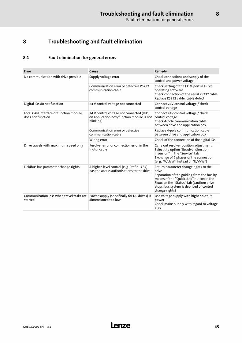
8.1 Fault elimination for general errors
Error Cause Remedy
No communication with drive possible Supply voltage error Check connections and supply of thecontrol and power voltage.
Communication error or defective RS232communication cable
Check setting of the COM port in Fluxxoperating softwareCheck connection of the serial RS232 cableReplace RS232 cable (cable defect)
Digital IOs do not function 24 V control voltage not connected Connect 24V control voltage / checkcontrol voltage
Local CAN interface or function moduledoes not function
24 V control voltage not connected (LEDon application box/function module is notblinking)
Connect 24V control voltage / checkcontrol voltageCheck 4-pole communication cablebetween drive and application box
Communication error or defectivecommunication cable
Replace 4-pole communication cablebetween drive and application box
Wiring error Check of the connection of the digital IOs
Drive travels with maximum speed only Resolver error or connection error in themotor cable
Carry out resolver position adjustmentSelect the option ”Resolver directioninversion” in the ”Service” tabExchange of 2 phases of the connection(e. g. ”V/U/W” instead of ”U/V/W”)
Fieldbus has parameter change rights A higher-level control (e. g. Profibus S7)has the access authorisations to the drive
Return parameter change rights to thedriveSeparation of the guiding from the bus bymeans of the ”Quick stop” button in theFluxx on the ”Status” tab (caution: drivestops, bus system is deprived of controlchange rights)
Communication loss when travel tasks arestarted
Power supply (specifically for DC drives) isdimensioned too low.
Use voltage supply with higher outputpowerCheck mains supply with regard to voltagedips
Troubleshooting and fault eliminationFault elimination for known error message (see Fluxx, ”Status” tab)
8
46 GHB 13.0002-EN 3.1
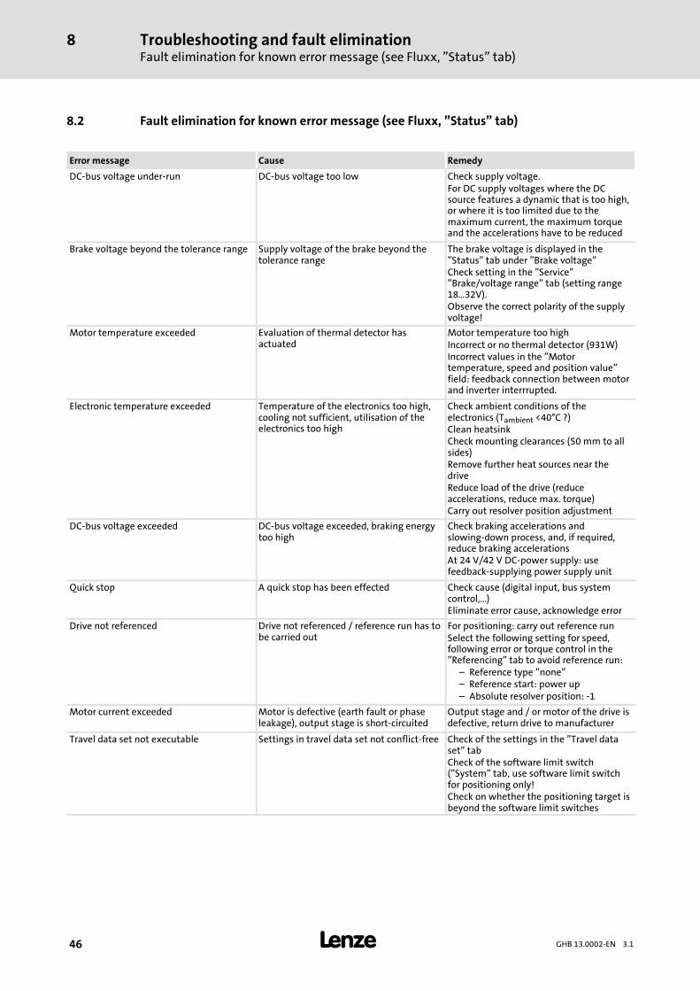
8.2 Fault elimination for known error message (see Fluxx, ”Status” tab)
Error message Cause Remedy
DC-bus voltage under-run DC-bus voltage too low Check supply voltage.For DC supply voltages where the DCsource features a dynamic that is too high,or where it is too limited due to themaximum current, the maximum torqueand the accelerations have to be reduced
Brake voltage beyond the tolerance range Supply voltage of the brake beyond thetolerance range
The brake voltage is displayed in the”Status” tab under ”Brake voltage”Check setting in the ”Service””Brake/voltage range” tab (setting range18…32V).Observe the correct polarity of the supplyvoltage!
Motor temperature exceeded Evaluation of thermal detector hasactuated
Motor temperature too highIncorrect or no thermal detector (931W)Incorrect values in the ”Motortemperature, speed and position value”field: feedback connection between motorand inverter interrrupted.
Electronic temperature exceeded Temperature of the electronics too high,cooling not sufficient, utilisation of theelectronics too high
Check ambient conditions of theelectronics (Tambient <40°C ?)Clean heatsinkCheck mounting clearances (50 mm to allsides)Remove further heat sources near thedriveReduce load of the drive (reduceaccelerations, reduce max. torque)Carry out resolver position adjustment
DC-bus voltage exceeded DC-bus voltage exceeded, braking energytoo high
Check braking accelerations andslowing-down process, and, if required,reduce braking accelerationsAt 24 V/42 V DC-power supply: usefeedback-supplying power supply unit
Quick stop A quick stop has been effected Check cause (digital input, bus systemcontrol,…)Eliminate error cause, acknowledge error
Drive not referenced Drive not referenced / reference run has tobe carried out
For positioning: carry out reference runSelect the following setting for speed,following error or torque control in the”Referencing” tab to avoid reference run:
– Reference type ”none”– Reference start: power up– Absolute resolver position: -1
Motor current exceeded Motor is defective (earth fault or phaseleakage), output stage is short-circuited
Output stage and / or motor of the drive isdefective, return drive to manufacturer
Travel data set not executable Settings in travel data set not conflict-free Check of the settings in the ”Travel dataset” tabCheck of the software limit switch(”System” tab, use software limit switchfor positioning only!Check on whether the positioning target isbeyond the software limit switches
Troubleshooting and fault eliminationFault elimination for known error message (see Fluxx, ”Status” tab)
8
47GHB 13.0002-EN 3.1
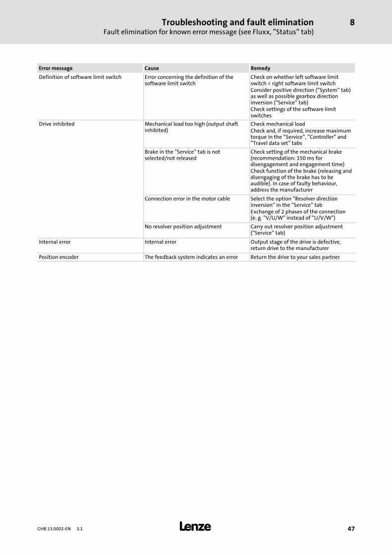
RemedyCauseError message
Definition of software limit switch Error concerning the definition of thesoftware limit switch
Check on whether left software limitswitch < right software limit switchConsider positive direction (”System” tab)as well as possible gearbox directioninversion (”Service” tab)Check settings of the software limitswitches
Drive inhibited Mechanical load too high (output shaftinhibited)
Check mechanical loadCheck and, if required, increase maximumtorque in the ”Service”, ”Controller” and”Travel data set” tabs
Brake in the ”Service” tab is notselected/not released
Check setting of the mechanical brake(recommendation: 150 ms fordisengagement and engagement time)Check function of the brake (releasing anddisengaging of the brake has to beaudible). In case of faulty behaviour,address the manufacturer
Connection error in the motor cable Select the option ”Resolver directioninversion” in the ”Service” tabExchange of 2 phases of the connection(e. g. ”V/U/W” instead of ”U/V/W”)
No resolver position adjustment Carry out resolver position adjustment(”Service” tab)
Internal error Internal error Output stage of the drive is defective,return drive to the manufacturer
Position encoder The feedback system indicates an error Return the drive to your sales partner
Troubleshooting and fault eliminationFault elimination for errors / problems with regard to the handling of bus systems
8
48 GHB 13.0002-EN 3.1
8.3 Fault elimination for errors / problems with regard to the handling of bus systems
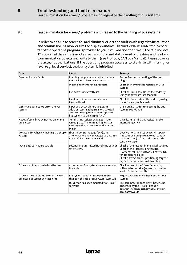
In order to be able to search for and eliminate errors and faults with regard to installationandcommissioningmoreeasily, thedisplaywindow”Display fieldbus”under the”Service”tabof theoperatingprogramisprovided toyou. If youobserve thedrive inthe ”Online level1”, youcanat the sametimeobserve the control and statusword of the driveand read andcommunication objects andwrite to them(see Profibus, CAN busManual). Pleaseobservethe access authorisations. If the operating program accesses to the drive within a higherlevel (e.g. level service), the bus system is inhibited.
Error Cause Remedy
Communication faults Bus plug not properly attached by snapmechanism or incorrectly connected
Ensure faultless mounting of the busplugs
Missing bus terminating resistors Check the terminating resistors of yoursystem
Bus address incorrectly set Check the bus addresses of the nodes byusing the software (see Manual)
Baud rate of one or several nodesincorrectly set
Check the baud rate of the nodes by usingthe software (see Manual)
Last node does not log on on the bussystem.
Input and output interchanged. Inaddition, terminating resistor activated.The terminating resistor interrupts thebus system to the output (X4.2)
Use input (X 4.1) for connecting the bussystem (see Manual)
Nodes after a drive do not log on on thebus system
Terminating resistor activated in thewrong place. The terminating resistorinterrupts the bus system to the output(X4.2)
Deactivate terminating resistor of theinterrupting drive
Voltage error when connecting the supplyvoltage
First the control voltage (24V), andafterwards the power voltage (24, 42, 230or 320 V) has been connected
Observe switch-on sequence. First power(the control is supplied automatically atthe same time). Afterwards connect thecontrol voltage
Travel data set not executable Settings in transmitted travel data set notconflict-free
Check of the settings in the travel data setCheck of the software limit switch(”System” tab) (use software limit switchfor positioning only)!Check on whether the positioning target isbeyond the software limit switches
Drive cannot be activated via the bus Access error. Bus system has no access tothe node
Check access of the ”Fluxx” operatingsoftware to the drive (access max. onlinelevel 1 for bus access!!!)
Drive can be started via the control word,but does not accept any setpoints
Bus system does not have parameterchange rights (see ”Bus system” Manual)
Request parameter change rights via bussystem
Quick stop has been actuated via ”Fluxx”software
The parameter change rights have to bedispensed by the ”Fluxx”. Requestparameter change rights via bus systemagain afterwards
AccessoriesTechnical documentation
9
49GHB 13.0002-EN 3.1
9 Accessories
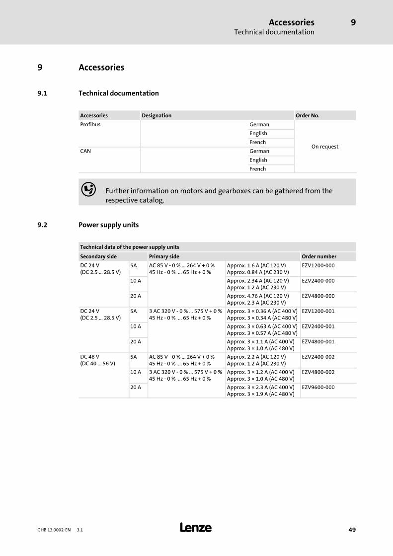
9.1 Technical documentation
Accessories Designation Order No.
Profibus German
On request
English
French
CAN German
English
French
Further information on motors and gearboxes can be gathered from therespective catalog.
9.2 Power supply units
Technical data of the power supply units
Secondary side Primary side Order number
DC 24 V(DC 2.5 ... 28.5 V)
5A AC 85 V - 0 % ... 264 V + 0 %45 Hz - 0 % ... 65 Hz + 0 %
Approx. 1.6 A (AC 120 V)Approx. 0.84 A (AC 230 V)
EZV1200-000
10 A Approx. 2.34 A (AC 120 V)Approx. 1.2 A (AC 230 V)
EZV2400-000
20 A Approx. 4.76 A (AC 120 V)Approx. 2.3 A (AC 230 V)
EZV4800-000
DC 24 V(DC 2.5 ... 28.5 V)
5A 3 AC 320 V - 0 % ... 575 V + 0 %45 Hz - 0 % ... 65 Hz + 0 %
Approx. 3 × 0.36 A (AC 400 V)Approx. 3 × 0.34 A (AC 480 V)
EZV1200-001
10 A Approx. 3 × 0.63 A (AC 400 V)Approx. 3 × 0.57 A (AC 480 V)
EZV2400-001
20 A Approx. 3 × 1.1 A (AC 400 V)Approx. 3 × 1.0 A (AC 480 V)
EZV4800-001
DC 48 V(DC 40 ... 56 V)
5A AC 85 V - 0 % ... 264 V + 0 %45 Hz - 0 % ... 65 Hz + 0 %
Approx. 2.2 A (AC 120 V)Approx. 1.2 A (AC 230 V)
EZV2400-002
10 A 3 AC 320 V - 0 % ... 575 V + 0 %45 Hz - 0 % ... 65 Hz + 0 %
Approx. 3 × 1.2 A (AC 400 V)Approx. 3 × 1.0 A (AC 480 V)
EZV4800-002
20 A Approx. 3 × 2.3 A (AC 400 V)Approx. 3 × 1.9 A (AC 480 V)
EZV9600-000
AccessoriesFunction modules for 930 series (M/W)
9
50 GHB 13.0002-EN 3.1
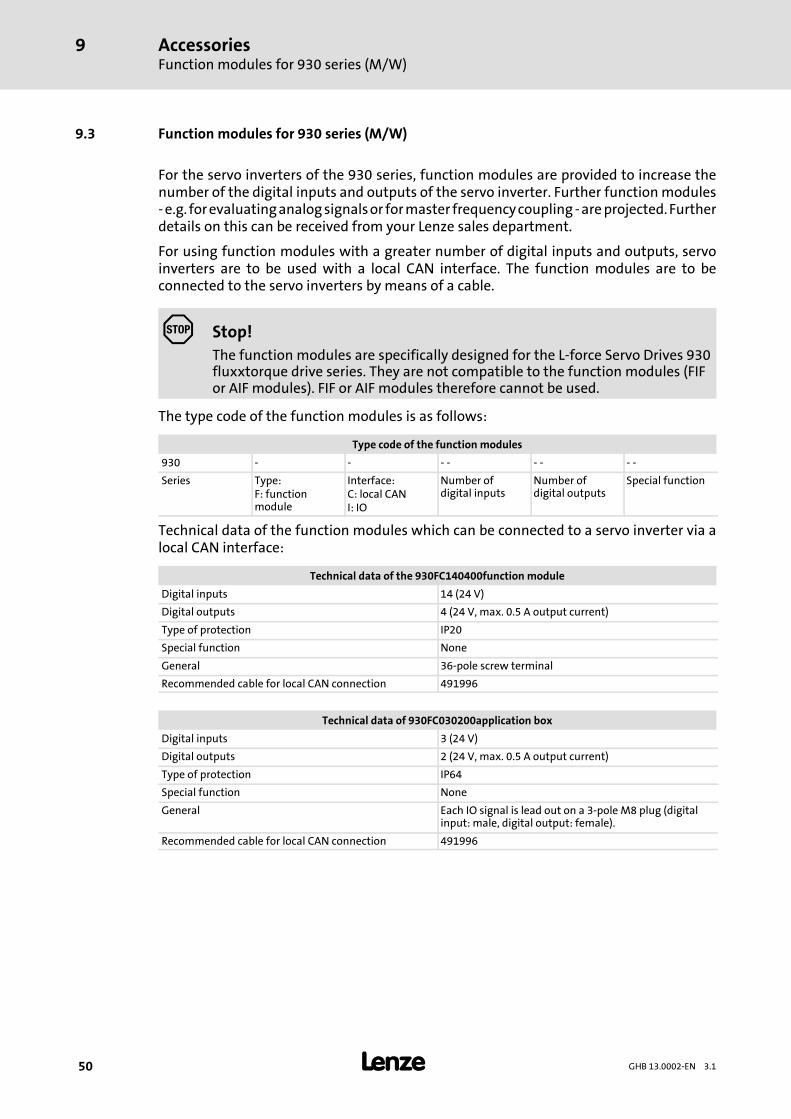
9.3 Function modules for 930 series (M/W)
For the servo inverters of the 930 series, function modules are provided to increase thenumber of the digital inputs and outputs of the servo inverter. Further functionmodules-e.g. forevaluatinganalogsignalsor formaster frequencycoupling -areprojected.Furtherdetails on this can be received from your Lenze sales department.
For using function modules with a greater number of digital inputs and outputs, servoinverters are to be used with a local CAN interface. The function modules are to beconnected to the servo inverters by means of a cable.
Stop!The function modules are specifically designed for the L-force Servo Drives 930fluxxtorque drive series. They are not compatible to the function modules (FIFor AIF modules). FIF or AIF modules therefore cannot be used.
The type code of the function modules is as follows:
Type code of the function modules
930 - - - - - - - -
Series Type:F: functionmodule
Interface:C: local CANI: IO
Number ofdigital inputs
Number ofdigital outputs
Special function
Technical data of the function modules which can be connected to a servo inverter via alocal CAN interface:
Technical data of the 930FC140400function module
Digital inputs 14 (24 V)
Digital outputs 4 (24 V, max. 0.5 A output current)
Type of protection IP20
Special function None
General 36-pole screw terminal
Recommended cable for local CAN connection 491996
Technical data of 930FC030200application box
Digital inputs 3 (24 V)
Digital outputs 2 (24 V, max. 0.5 A output current)
Type of protection IP64
Special function None
General Each IO signal is lead out on a 3-pole M8 plug (digitalinput: male, digital output: female).
Recommended cable for local CAN connection 491996
AccessoriesFunction modules for 930 series (M/W)
9
51GHB 13.0002-EN 3.1
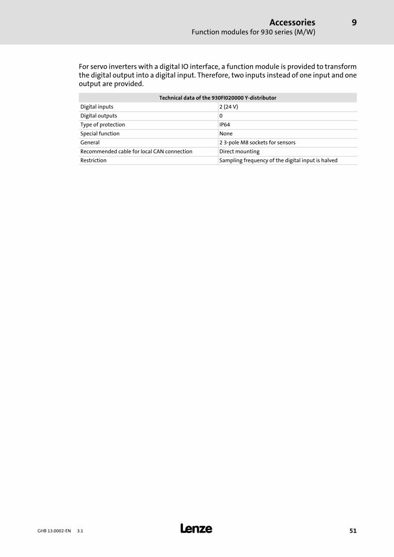
For servo inverters with a digital IO interface, a functionmodule is provided to transformthe digital output into a digital input. Therefore, two inputs instead of one input and oneoutput are provided.
Technical data of the 930FI020000 Y-distributor
Digital inputs 2 (24 V)
Digital outputs 0
Type of protection IP64
Special function None
General 2 3-pole M8 sockets for sensors
Recommended cable for local CAN connection Direct mounting
Restriction Sampling frequency of the digital input is halved
AppendixDimensions of 931M 24 V or 42 V DC, simple mounting (resolver)
10
52 GHB 13.0002-EN 3.1
10 Appendix
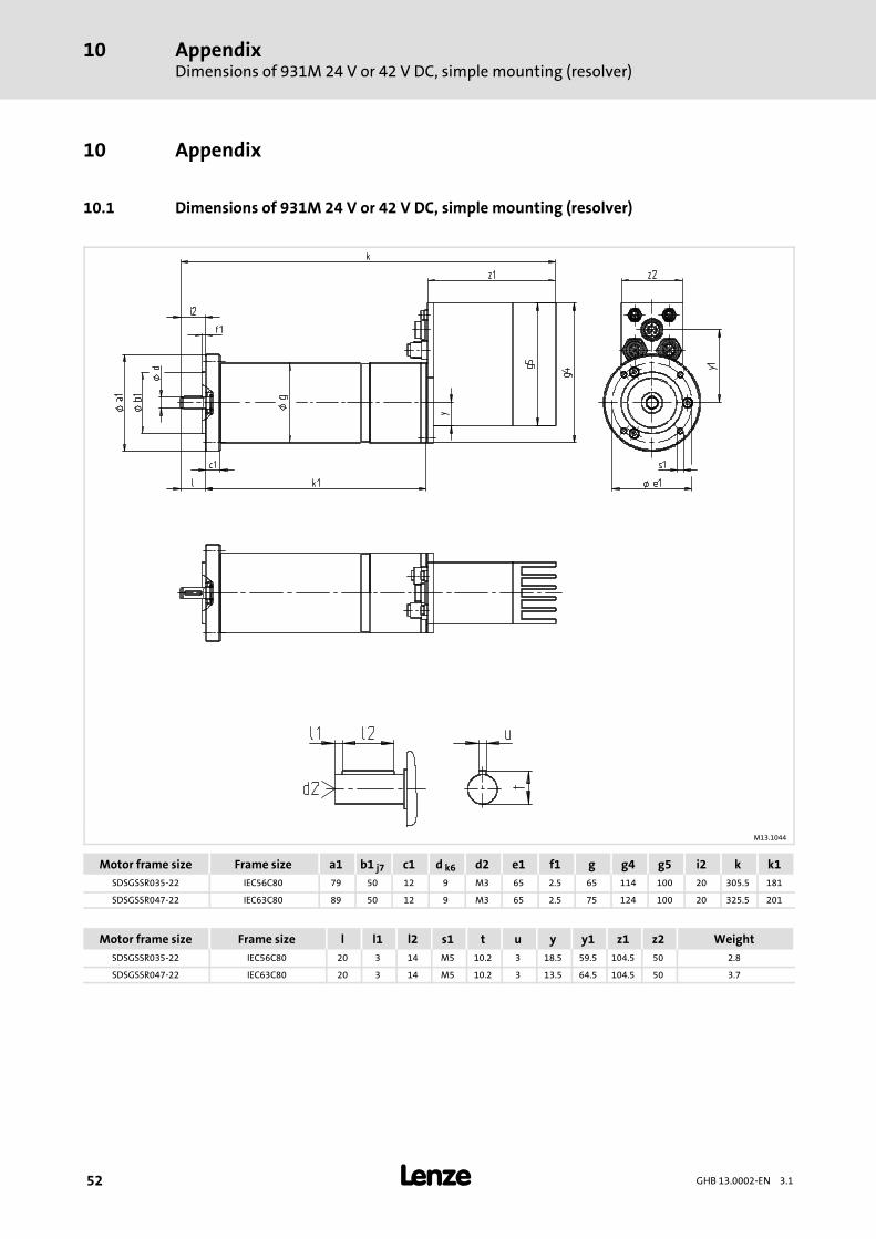
10.1 Dimensions of 931M 24 V or 42 V DC, simple mounting (resolver)
M13.1044
Motor frame size Frame size a1 b1 j7 c1 d k6 d2 e1 f1 g g4 g5 i2 k k1SDSGSSR035-22 IEC56C80 79 50 12 9 M3 65 2.5 65 114 100 20 305.5 181
SDSGSSR047-22 IEC63C80 89 50 12 9 M3 65 2.5 75 124 100 20 325.5 201
Motor frame size Frame size l l1 l2 s1 t u y y1 z1 z2 WeightSDSGSSR035-22 IEC56C80 20 3 14 M5 10.2 3 18.5 59.5 104.5 50 2.8
SDSGSSR047-22 IEC63C80 20 3 14 M5 10.2 3 13.5 64.5 104.5 50 3.7
AppendixDimensions of 931M 230 V AC or 320 V DC, simple mounting (resolver)
10
53GHB 13.0002-EN 3.1
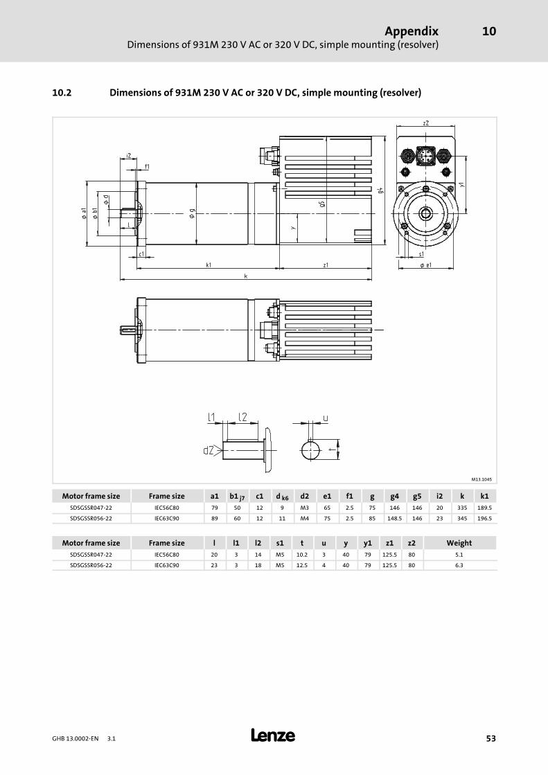
10.2 Dimensions of 931M 230 V AC or 320 V DC, simple mounting (resolver)
M13.1045
Motor frame size Frame size a1 b1 j7 c1 d k6 d2 e1 f1 g g4 g5 i2 k k1SDSGSSR047-22 IEC56C80 79 50 12 9 M3 65 2.5 75 146 146 20 335 189.5
SDSGSSR056-22 IEC63C90 89 60 12 11 M4 75 2.5 85 148.5 146 23 345 196.5
Motor frame size Frame size l l1 l2 s1 t u y y1 z1 z2 WeightSDSGSSR047-22 IEC56C80 20 3 14 M5 10.2 3 40 79 125.5 80 5.1
SDSGSSR056-22 IEC63C90 23 3 18 M5 12.5 4 40 79 125.5 80 6.3
AppendixDimensions of 931M 24 V or 42 V DC, double mounting (resolver + brake)
10
54 GHB 13.0002-EN 3.1
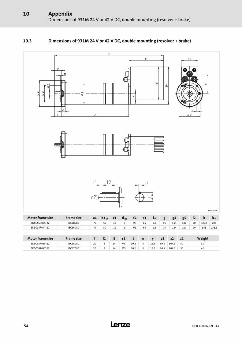
10.3 Dimensions of 931M 24 V or 42 V DC, double mounting (resolver + brake)
M13.1066
Motor frame size Frame size a1 b1 j7 c1 d k6 d2 e1 f1 g g4 g5 i2 k k1SDSGSSR035-22 IEC58C80 79 50 12 9 M3 65 2.5 65 114 100 20 329.5 205
SDSGSSR047-22 IEC56C80 79 50 12 9 M3 65 2.5 75 124 100 20 358 233.5
Motor frame size Frame size l l1 l2 s1 t u y y1 z1 z2 WeightSDSGSSR035-22 IEC58C80 20 3 14 M5 10.2 3 18.5 59.5 104.5 50 3.3
SDSGSSR047-22 IEC57C80 20 3 14 M5 10.2 3 18.5 64.5 104.5 50 4.3
AppendixDimensions of 931M 230 V AC or 320 V DC, double mounting (resolver + brake)
10
55GHB 13.0002-EN 3.1
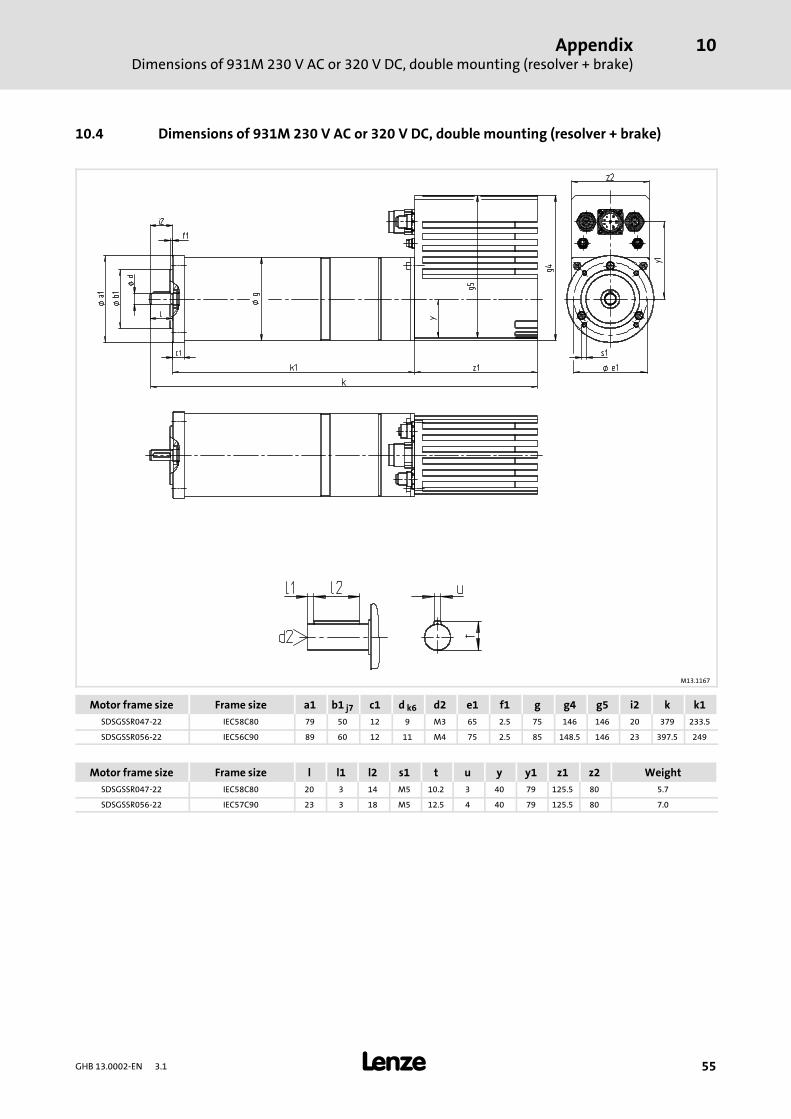
10.4 Dimensions of 931M 230 V AC or 320 V DC, double mounting (resolver + brake)
M13.1167
Motor frame size Frame size a1 b1 j7 c1 d k6 d2 e1 f1 g g4 g5 i2 k k1SDSGSSR047-22 IEC58C80 79 50 12 9 M3 65 2.5 75 146 146 20 379 233.5
SDSGSSR056-22 IEC56C90 89 60 12 11 M4 75 2.5 85 148.5 146 23 397.5 249
Motor frame size Frame size l l1 l2 s1 t u y y1 z1 z2 WeightSDSGSSR047-22 IEC58C80 20 3 14 M5 10.2 3 40 79 125.5 80 5.7
SDSGSSR056-22 IEC57C90 23 3 18 M5 12.5 4 40 79 125.5 80 7.0
AppendixVoltage supply for type 931M 24 V or 42 V
10
56 GHB 13.0002-EN 3.1
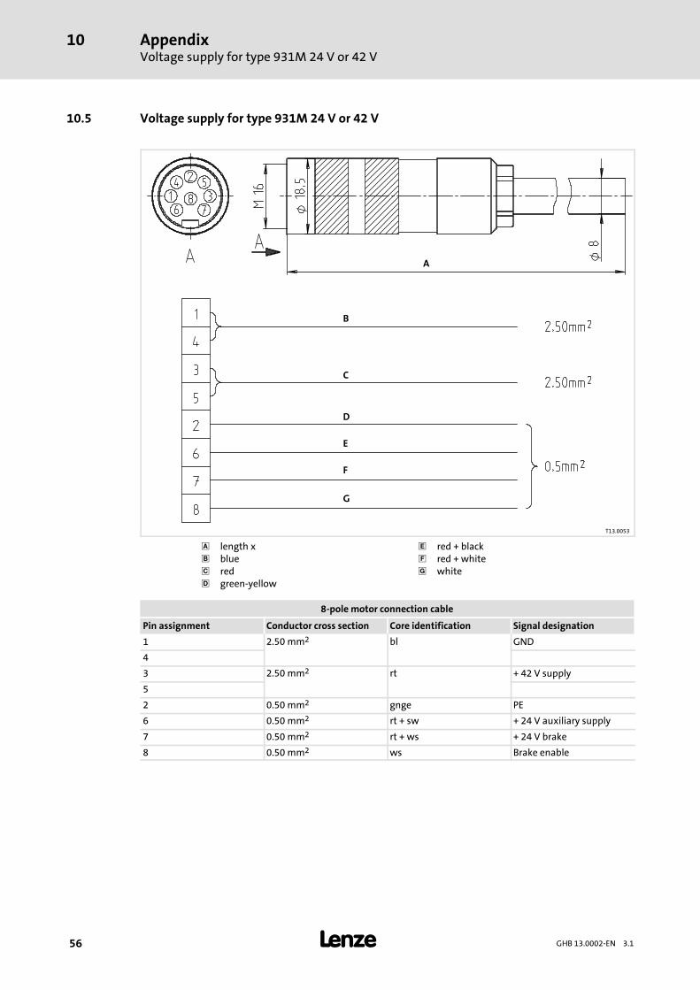
10.5 Voltage supply for type 931M 24 V or 42 V
A
B
D
C
E
F
G
T13.0053
length x red + black blue red + white red white green-yellow
8-pole motor connection cable
Pin assignment Conductor cross section Core identification Signal designation
1 2.50 mm2 bl GND
4
3 2.50 mm2 rt + 42 V supply
5
2 0.50 mm2 gnge PE
6 0.50 mm2 rt + sw + 24 V auxiliary supply
7 0.50 mm2 rt + ws + 24 V brake
8 0.50 mm2 ws Brake enable
AppendixVoltage supply for type 931M 230 V or 320 V
10
57GHB 13.0002-EN 3.1
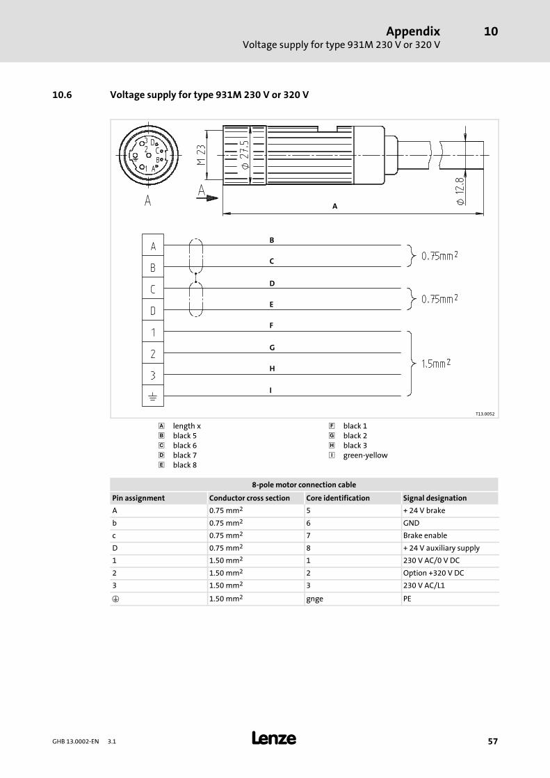
10.6 Voltage supply for type 931M 230 V or 320 V
A
B
D
C
E
F
G
H
I
T13.0052
length x black 1 black 5 black 2 black 6 black 3 black 7 green-yellow black 8
8-pole motor connection cable
Pin assignment Conductor cross section Core identification Signal designation
A 0.75 mm2 5 + 24 V brake
b 0.75 mm2 6 GND
c 0.75 mm2 7 Brake enable
D 0.75 mm2 8 + 24 V auxiliary supply
1 1.50 mm2 1 230 V AC/0 V DC
2 1.50 mm2 2 Option +320 V DC
3 1.50 mm2 3 230 V AC/L1
1.50 mm2 gnge PE
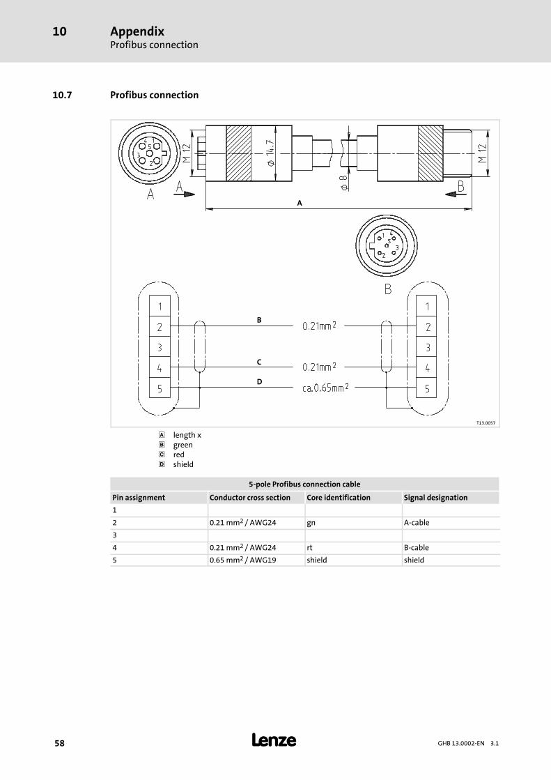
AppendixProfibus connection
10
58 GHB 13.0002-EN 3.1
10.7 Profibus connection
A
B
D
C
T13.0057
length x green red shield
5-pole Profibus connection cable
Pin assignment Conductor cross section Core identification Signal designation
1
2 0.21 mm2 / AWG24 gn A-cable
3
4 0.21 mm2 / AWG24 rt B-cable
5 0.65 mm2 / AWG19 shield shield
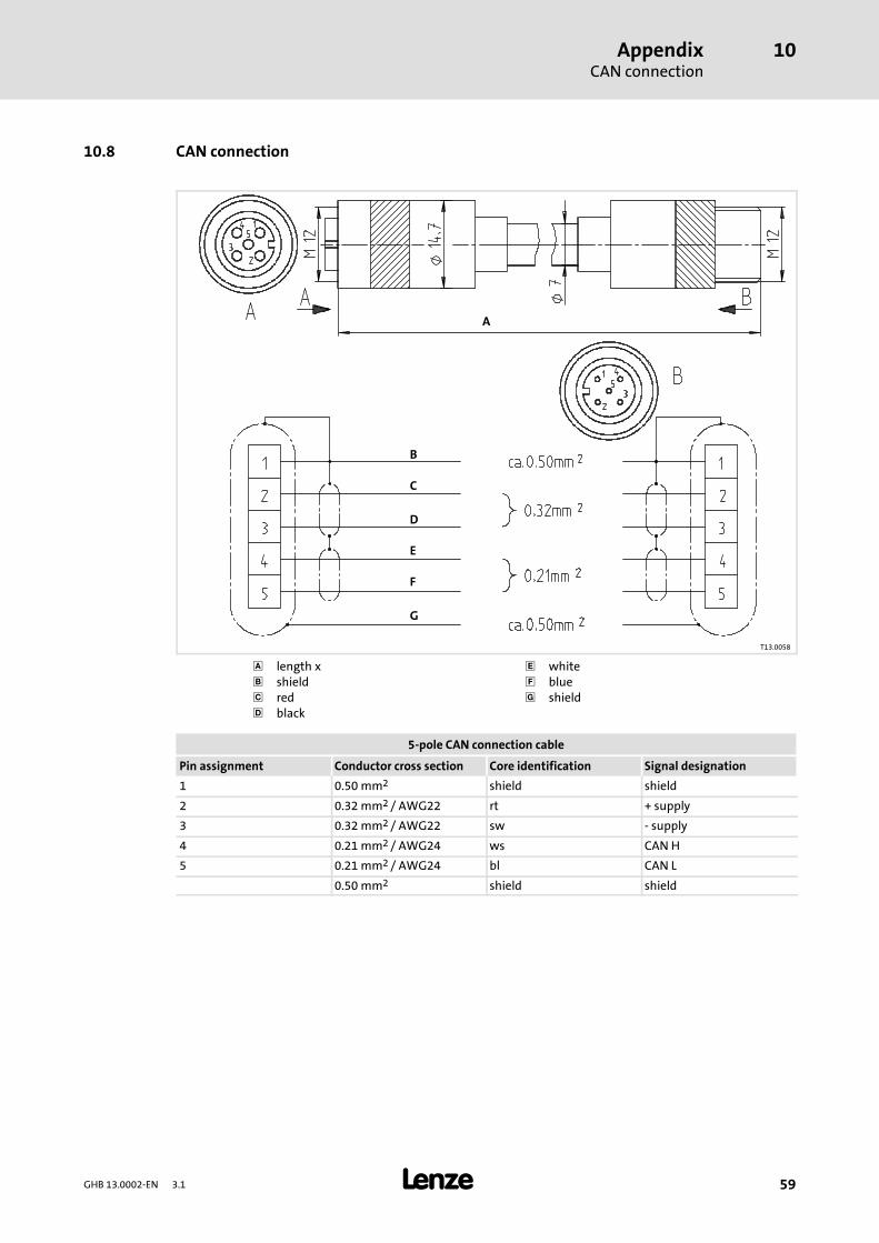
AppendixCAN connection
10
59GHB 13.0002-EN 3.1
10.8 CAN connection
A
B
D
C
E
G
F
T13.0058
length x white shield blue red shield black
5-pole CAN connection cable
Pin assignment Conductor cross section Core identification Signal designation
1 0.50 mm2 shield shield
2 0.32 mm2 / AWG22 rt + supply
3 0.32 mm2 / AWG22 sw - supply
4 0.21 mm2 / AWG24 ws CAN H
5 0.21 mm2 / AWG24 bl CAN L
0.50 mm2 shield shield
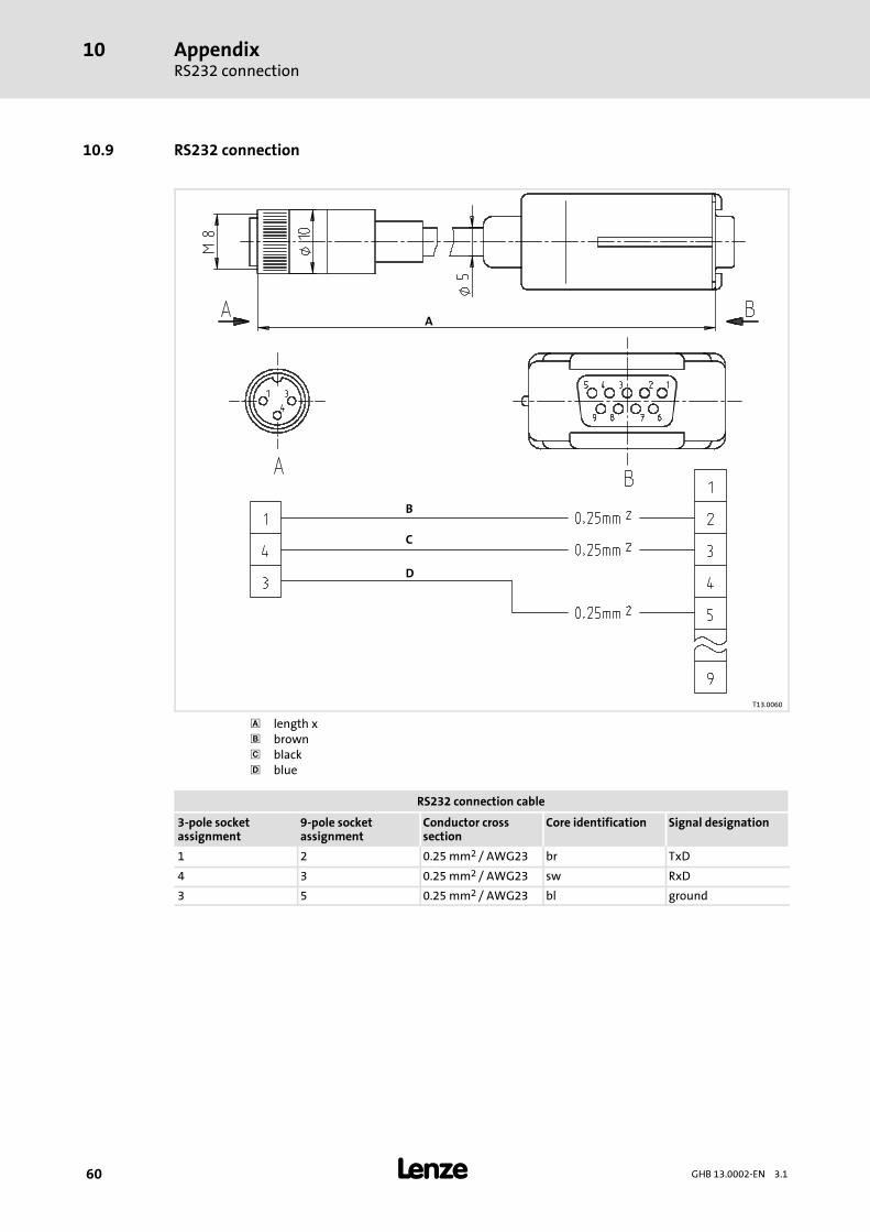
AppendixRS232 connection
10
60 GHB 13.0002-EN 3.1
10.9 RS232 connection
A
B
D
C
T13.0060
length x brown black blue
RS232 connection cable
3-pole socketassignment
9-pole socketassignment
Conductor crosssection
Core identification Signal designation
1 2 0.25 mm2 / AWG23 br TxD
4 3 0.25 mm2 / AWG23 sw RxD
3 5 0.25 mm2 / AWG23 bl ground
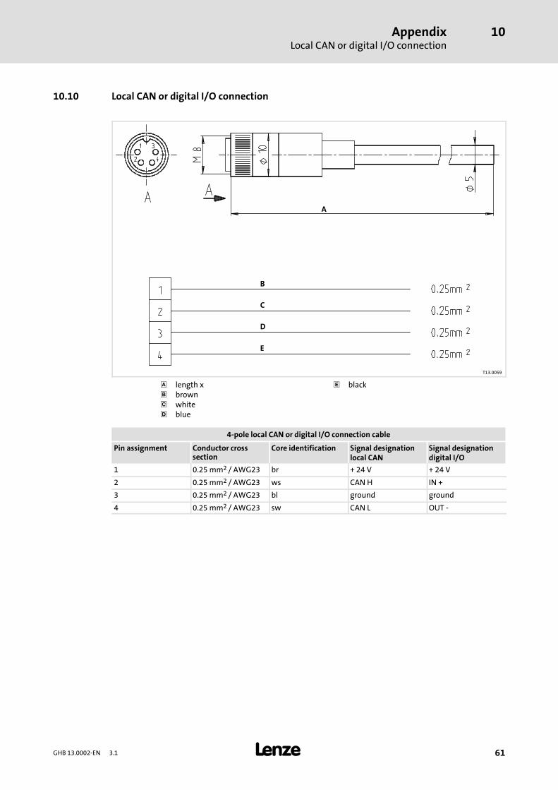
AppendixLocal CAN or digital I/O connection
10
61GHB 13.0002-EN 3.1
10.10 Local CAN or digital I/O connection
A
B
D
C
E
T13.0059
length x black brown white blue
4-pole local CAN or digital I/O connection cable
Pin assignment Conductor crosssection
Core identification Signal designationlocal CAN
Signal designationdigital I/O
1 0.25 mm2 / AWG23 br + 24 V + 24 V
2 0.25 mm2 / AWG23 ws CAN H IN +
3 0.25 mm2 / AWG23 bl ground ground
4 0.25 mm2 / AWG23 sw CAN L OUT -
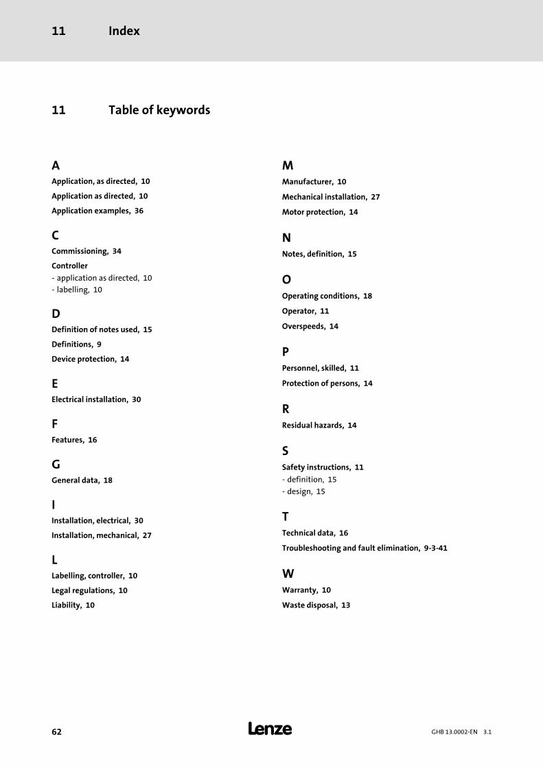
Index11
62 GHB 13.0002-EN 3.1
11 Table of keywords
AApplication, as directed, 10
Application as directed, 10
Application examples, 36
CCommissioning, 34
Controller
- application as directed, 10
- labelling, 10
DDefinition of notes used, 15
Definitions, 9
Device protection, 14
EElectrical installation, 30
FFeatures, 16
GGeneral data, 18
IInstallation, electrical, 30
Installation, mechanical, 27
LLabelling, controller, 10
Legal regulations, 10
Liability, 10
MManufacturer, 10
Mechanical installation, 27
Motor protection, 14
NNotes, definition, 15
OOperating conditions, 18
Operator, 11
Overspeeds, 14
PPersonnel, skilled, 11
Protection of persons, 14
RResidual hazards, 14
SSafety instructions, 11
- definition, 15
- design, 15
TTechnical data, 16
Troubleshooting and fault elimination, 9-3-41
WWarranty, 10
Waste disposal, 13

Notes
63GHB 13.0002-EN 3.1

Notes
64 GHB 13.0002-EN 3.1

Notes
65GHB 13.0002-EN 3.1
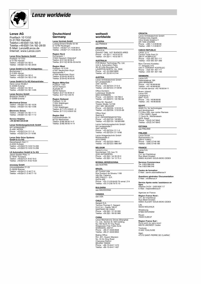
Lenze worldwide
Lenze AGPostfach 10 13 52D-31763 HamelnTelefon+49 (0)51 54 / 82-0Telefax +49 (0)51 54 / 82-28 00E-Mail: [email protected]: www.Lenze.com
Lenze Drive Systems GmbH Postfach 10 13 52D-31763 HamelnTelefon +49 (0)51 54 / 82-0Telefax +49 (0)51 54 / 82-28 00
Lenze GmbH & Co KG AnlagenbauBuchenweg 1D-31855 AerzenTelefon +49 (0)51 54 / 82-0Telefax +49 (0)51 54 / 82-21 00
Lenze GmbH & Co KG KleinantriebeHans-Lenze-Straße 1D-32699 ExtertalTelefon +49 (0)51 54 / 82-0Telefax +49 (0)51 54 / 82-14 85
Lenze Service GmbHBreslauer Straße 3D-32699 Extertal
Mechanical DrivesTelefon +49 (0)51 54 / 82-16 26Telefax +49 (0)51 54 / 82-13 96
Electronic DrivesTelefon +49 (0)51 54 / 82-11 11Telefax +49 (0)51 54 / 82-11 12
Service Helpline +49 (0)180 5 20 24 26
Lenze Verbindungstechnik GmbHIpf-Landesstraße 1A-4481 ASTENPhone +43 (0)72 24 / 21 1-0Telefax +43 (0)72 24 / 21 19 98
Lenze Deto Drive Systems GmbH & Co KGGewerbepark Süd 11A-6330 KufsteinTelefon +43 (0)53 72 / 6 53 15-200Telefax +43 (0)53 72 / 6 53 15-299
LS Automation GmbH & Co KGJakob-Stadler-Platz 11D-78467 KonstanzTelefon +49 (0)75 31 /9 42 19-0Telefax +49 (0)75 31 /9 42 19 20
encoway GmbHUniversitätsallee 21-23D-28359 BremenTelefon +49 (0)4 21 /2 46 77-0Telefax +49 (0)4 21 /2 46 77-10
DeutschlandGermanyLenze Vertrieb GmbH Ludwig-Erhard-Straße 52-56D-72760 ReutlingenTelefon +49 (0)71 21 / 9 39 39-0Telefax +49 (0)71 21 / 9 39 39-29
Region NordDornenpark 131840 Hessisch OldendorfTelefon (0 51 52) 90 36-0Telefax (0 51 52) 90 36-33/44/55
Region WestPostfach 10 12 2047497 Neukirchen-VluynKelvinstraße 747506 Neukirchen-VluynTelefon (0 28 45) 95 93-0Telefax (0 28 45) 95 93 93
Region Mitte/OstPostfach 146335724 HerbornAustraße 8135745 HerbornTelefon (0 27 72) 95 94-0Telefax (0 27 72) 5 30 79
Region SüdwestPostfach 14 3371304 WaiblingenSchänzle 871332 WaiblingenTelefon (0 71 51) 9 59 81 - 0Telefax (0 71 51) 9 59 81 50
Region SüdFraunhoferstraße 1682152 MartinsriedTelefon (0 89) 89 56 14-0Telefax (0 89) 89 56 14 14
weltweitworldwideALGERIAsee FRANCE
ARGENTINAE.R.H.S.A.Girardot 1368, 1427 BUENOS AIRESPhone +54 (0)11 / 45 54 32 32Telefax +54 (0)11 / 45 52 36 11
AUSTRALIAFCR Motion Technology Pty. Ltd.Unit 6, Automation Place38-40 Little Boundary Rd.LAVERTON NORTH, Vic. 3026 Phone +61 (3) 9362 6800 Telefax +61 (3) 9314 3744
AUSTRIALenze Antriebstechnik GmbHIpf-Landesstraße 14481 ASTENPhone +43 (0)7224 / 21 0-0Telefax +43 (0)7224 / 21 09 99
Office Dornbirn:Lustenauer Straße 646850 DORNBIRN Phone +43 (0)5572 / 26 789-0Telefax +43 (0)5572 / 26 789-66
Office Wr. Neudorf:Triester Straße 14/1092351 WR. NEUDORFPhone +43 (0)2236 / 2 53 33-0Telefax +43 (0)2236 / 2 53 33-66
Office Graz:Seering 88141 UNTERPREMSTÄTTENPhone +43 (0)3135 / 56 900-0Telefax +43 (0)3135 / 56 900 999
Lenze Verbindungstechnik GmbHIpf-Landesstraße 14481 ASTENPhone +43 (0)7224 / 21 1-0Telefax +43 (0)7224 / 21 19 98
Lenze Anlagentechnik GmbHMühlenstraße 34470 ENNSPhone +43 (0)7223 / 886-0Telefax +43 (0)7223 / 886-997
BELGIUMLenze b.v.b.aNoorderlaan 133, bus 152030 ANTWERPENPhone +32 (0)3 / 54 26 20 0Telefax +32 (0)3 / 54 13 75 4
BOSNIA-HERZEGOVINAsee AUSTRIA
BRAZILAC Control LtdaRua Gustavo da Silveira 1199 Vila Sta. CatarinaSÃO PAULO – S.P.04376-000Phone +55 (11) 55 64 65 79 ramal: 214Telefax +55 (11) 56 79 75 10
BULGARIAsee MACEDONIA
CANADAsee USA
CHILE Sargent S.A.Tecnica Thomas C. SargentS.A.C.é.l., Casilla 166-DSANTIAGO DE CHILEPhone +56 (0)2 / 51 03 000Telefax +56 (0)2 / 69 83 989
CHINALenze Mechatronic Drives (Shanghai) Co. Ltd., Section B, 50# building,No.199 North Ri Ying Road,Waigaoqiao Free Trade ZoneSHANGHAI, 200131Phone +86-21-5046 0848Telefax +86-21-5046 0850
Beijing OfficeRm. 401, Huaxin MansionNo. 33 An Ding RoadChaoyang DistrictBEIJING 100029Phone +86-10-6441 1470Telefax +86-10-6441 1467
CROATIALenze Antriebstechnik GmbHPredstavnista ZagrebUlica Grada Gospica 3HR-1000 ZAGREBPhone +385-1-2 49 80 56Telefax +385-1-2 49 80 57
CZECH REPUBLICLenze, s.r.o.Central Trade Park D1396 01 HUMPOLECPhone +420 565 507-111Telefax +420 565 507-399
Büro âerven˘ Kostelec:17. listopadu 510 549 41 âERVEN¯ KOSTELECPhone +420 491 467-111Telefax +420 491 467-166
DENMARKLenze A/SVallensbækvej 18A2605 BRØNDBYPhone +45 / 46 96 66 66Telefax +45 / 46 96 66 6024 stunde service +45 / 40 93 04 11
Buero Jylland:Lenze A/SLanghøjvej 18381 TILSTPhone +45 / 46 96 66 66Telefax +45 / 46 96 66 80
EGYPTWADI Co. for technologies and developmentP.O.Box 209, new center Ramses11794 CAIRO, Egypt11 Syria St., MohandessinGIZA, EgyptPhone +20 (2) 347 6842Telefax +20 (2) 347 6843
ESTONIAsee FINLAND
FINLANDLenze DrivesRykmentintie 2 b20810 TURKUPhone +358 2 2748 180Telefax +358 2 2748 189
FRANCELenze S.A.SiegeZ.A. de ChanteloupRue Albert Einstein93603 AULNAY-SOUS-BOIS CEDEX
Services CommerciauxTel. 0 825 086 036Fax 0 825 086 346
Centre de formationE-Mail : [email protected]
Questions générales / DocumentationE-Mail : [email protected]
Service Après-vente / assistance enligneHelpline 24/24 : 0 825 826 117 E-Mail : [email protected]
Agences en France
Région France Nord :Z.A. de ChanteloupRue Albert Einstein93603 AULNAY-SOUS-BOIS CEDEX
Lille59420 MOUVAUX
Strasbourg67960 ENTZHEIM
Rouen76500 ELBEUF
Région France Sud :Rond point du sans souci69578 LIMONEST Cedex
Toulouse31400 TOULOUSE
Agen47270 SAINT-PIERRE DE CLAIRAC
Lenze worldwide
GREECEGeorge P. Alexandris S.A.12K. Mavromichali Str.185 45 PIRAEUSPhone +30 (0)210 / 41 11 84 15Telefax +30 (0)210 / 4 11 81 71
4 12 70 58183 Monastiriou Str. 546 27 THESSALONIKIPhone +30 (0)310 / 5 56 65 04Telefax +30 (0)310 / 51 18 15
HUNGARYLenze Antriebstechnik HandelsgesellschaftmbH2040 BUDAÖRSGyár utca 2., P.O.Box 322.Phone +36 (0)23 / 501-320Telefax +36 (0)23 / 501-339
ICELANDsee DENMARK
INDIAElectronic Service:National Power Systems,10, Saibaba Shopping CentreKeshav Rao Kadam Marg,Off Lamington Rd,MUMBAI 400 008Phone +91 22 / 2300 5667, 2301 3712 Telefax +91 22 / 2300 5668
V3 Controls Pvt. Ltd.1, “Devyani”, Next to SBI, Baner ITI Road,Sanewadi, Aundh,PUNE 411 007, MSPhone +91 20 / 25 88 68 62Telefax +91 20 / 25 88 03 50
Mechanical Service:Emco Lenze Pvt. Ltd.1st Floor, Sita MauliMadanlal Dhingra RoadPanch Pakhadi, Thane (West)MAHARASHATRA 400 602Phone +91 22 / 25 40 54 88
+91 22 / 25 45 22 44Telefax +91 22 / 25 45 22 33
INDONESIAP.T. Futurindo GlobalsatyaJl.: Prof. Dr. Latumenten No. 18Kompleks PerkantoranKota Grogol Permai Blok A 35JAKARTA 11460Buero 1:Phone +62 (0)21 / 766 42 34
765 86 23Telefax +62 (0)21 / 766 44 20Buero 2:Phone +62 (0)21 / 567 96 31
567 96 32Telefax +62 (0)21 / 566 87 50
IRANTavan Ressan Co. Ltd.P.O.Box. 19395-5177, No. 44, Habibi St.,South Dastour St., Sadr EXP’Way,TEHRAN 19396Phone +98 21 / 260 26 55
260 67 66260 92 99
Telefax +98 21 / 200 28 83
ISRAELGreenshpon Engineering Works LTDBar-Lev Industrial ParkMISGAV 20179Phone +972 4 99 13 18 1Telefax +972 4 99 13 47 7
ITALYGerit Trasmissioni S.p.A.Viale Monza 33820128 MILANOPhone +39 02 / 270 98.1Telefax +39 02 / 270 98 290
JAPANMiki Pulley Co., Ltd.1-39-7 KomatsubaraZama-cityKANAGAWA 228-8577Phone +81 (0)462 / 58 16 61Telefax +81 (0)462 / 58 17 04
LATVIAsee LITHUANIA
LITHUANIALenze UABBreslaujos g.344403 KAUNASPhone +370 37 407174Telefax +370 37 407175
LUXEMBOURGsee BELGIUM
MACEDONIALenze Antriebstechnik GmbHPretstavnistvo Skopjeul. Nikola Rusinski 3/A/21000 SKOPJEPhone +389 2 30 90 090Telefax +389 2 30 90 091
MALAYSIAD.S.C. Engineering SDN BHD3A & 3B, Jalan SS21/56BDamansara Utama47400, PETALING JAYA, SELANGOR Phone +60 (0)3 / 77 25 62 43
77 25 62 4677 28 65 30
Telefax +60 (0)3 / 77 29 50 31
Lenze S.E.A. Sdn BhdDamansara Technology ParkNo. 28, Jalan PJU 3/4747810, PETALING JAYA, SELANGOR
MAURITIUSAutomation & Controls Engineering Ltd3, Royal Road, Le Hochet, Terre RougeMAURITIUSPhone +230 248 8211Telefax +230 248 8968
MEXICOAutomatización y Control de Energía S.A. de C.V.Av. 2 No. 89 Esq Calle 13Col. San Pedro de los PinosC.P. 03800 MEXICO D.F.Phone +52 (55)5277/5998Telefax +52 (55)5277/5937
MOROCCOGUORFET G.T.D.R Automatisation IndustrielleBd Chefchaouni Route 110 km, 11.500No. 353-Aîn-SabaâCASABLANCAPhone +212/22-35 70 78Telefax +212/22-35 71 04
NETHERLANDSLenze B.V., Postbus 31 015203 DC`S-HERTOGENBOSCHPloegweg 155232 BR`S-HERTOGENBOSCHPhone +31 (0)73 / 64 56 50 0Telefax +31 (0)73 / 64 56 51 0
NEW ZEALANDTranz Corporation343 Church StreetP.O. Box 12-320, PenroseAUCKLANDPhone +64 (0)9 / 63 45 51 1Telefax +64 (0)9 / 63 45 51 8
NORWAYDtc- Lenze asStallbakken 5, 2005 RAELINGENPhone +47 / 64 80 25 10Telefax +47 / 64 80 25 11
PHILIPPINESJupp & Company Inc.Unit 224 Cityland Pioneer Bldg.,Pioneer StreetMANDALUYONG CITYPhone +63 2 / 687 7423
683 0042683 0047
Telefax +63 2 / 687 7421
POLANDLenze-Rotiw Sp. z o.o.ul. Ro˝dzieƒskiego 188b40-203 KATOWICEPhone +48 (0)32 / 2 03 97 73Telefax +48 (0)32 / 7 81 01 80
Lenze Systemy Automatyki Sp. z o.o.Ul. Rydygiera 4787-100 TORU¡Phone +48 (0)56 / 6 58 28 00
6 45 34 606 45 35 70
Telefax +48 (0)56 / 6 45 33 56
PORTUGALCosta Leal el VictorElectronica-Pneumatica, Lda.Rua Prof. Augusto Lessa, 269,Apart. 520534202-801 PORTOPhone +351-22 / 5 50 85 20Telefax +351-22 / 5 02 40 05
ROMANIAsee AUSTRIA
RUSSIAInteldrive1 Buhvostova Street 12/11Korpus 18 Office 322MOSCOW 107258Phone +7 (0)095 / 963 96 86Telefax +7 (0)095 / 962 67 94
SERBIA-MONTENEGROsee MACEDONIA
SINGAPOREsee MALAYSIA
SLOVAC REPUBLICECS Sluzby spol. s.r.o.Staromlynska 2982106 BRATISLAVAPhone +421 2 45 25 96 06
+421 2 45 64 31 47+421 2 45 64 31 48
Telefax +421 2 45 25 96 06
SLOVENIALenze pogonska tehnika GmbHZbiljska Cesta 41215 MEDVODEPhone +386 (0)1 361 61 41Telefax +386 (0)1 361 22 88
SOUTH AFRICAS.A. Power Services (Pty.) Ltd.Unit 14, Meadowbrook Business EstatesJacaranda Ave, OlivedaleRandburg 2158, P.O.Box 1137RANDBURG 2125Phone +27(11) 462-8810Telefax +27(11) 704-5775
SOUTH KOREAHankuk Mechatro Ltd.Room# 1409, Samhwan officetel 830-295Beomil-dong, Dong-GuPUSANPhone +82 (0)51-635-6663Telefax +82 (0)51-635-6632
SPAINLenze Transmisiones, S.A. (Headquarter)Milà i Fontanals, 135-13908205 SABADELLBarcelona Phone +34 937 207 680Telefax +34 937 120 215
Lenze Delegación BilbaoP.I. Ibarrabarri. Ed. METRO 2º-E48940 LEJONAVizcayaPhone +34 944 630 510/ 507Telefax +34 944 314 196
Lenze Delegación LevanteCullera, 73 – 4ºD46035 BENIMAMET ValenciaPhone +34 963 905 220/335Telefax +34 963 900 647
Lenze Delegación MadridArturo Soria, 187 – Of. 828043 MADRID Phone +34 915 103 341Telefax +34 915 102 061
SWEDENLenze Transmissioner ABP.O.Box 10 74, Attorpsgatan, Tornby Ind.58110 LINKÖPINGPhone +46 (0)13 / 35 58 00Telefax +46 (0)13 / 10 36 23
SWITZERLANDLenze Bachofen AGAckerstrasse 458610 USTERPhone +41 (0) 43 399 14 14Telefax +41 (0) 43 399 14 24
Vente Suisse Romande:Route de Prilly 251023 CRISSIERPhone +41 (0)21 / 63 72 19 0Telefax +41 (0)21 / 63 72 19 9
SYRIAZahabi Co.8/5 Shouhadaa StreetP.O.Box 8262ALEPPO-SYRIAPhone +963 21 21 22 23 5Telefax +963 21 21 22 23 7
TAIWANACE Pillar Co. Ltd.No.12, Lane 61, Sec. 1, Kuanfu RoadSan-Chung CityTAIPEI HSIENPhone +886 (0)2 / 299 58 40 0Telefax +886 (0)2 / 299 53 46 6
THAILANDPackSys Global (Thailand) Ltd.429 Moo 7, Theparak Road, Tambol TheparakAmphur MuangSAMUTPRAKARN 10270Phone +66 2 383 5633Telefax +66 2 383 5637
TUNESIAAMF Industrielle SarlRoute de Gremda - Km 0,2Immeuble El Madina,Centre Bloc B - 5 ème - appt 523002 SFAXPhone +216 74 403 514Telefax +216 74 402 516
TURKEYLSE Elektrik Elektronik MakinaOtomasyon Mühendislik San. Ve Tic. Ltd. Ωti.Atatürk mah. Cumhuriyet cad.Yurt sok. No:7ÜMRANIYE/∑STANBULPhone +90 (0)216 / 316 5138 pbxTelefax +90 (0)216 / 443 4277
Bursa Address:Demirtaspasa Mh.Ata Sk. Petek Bozkaya Is MerkeziD Blok No :5 / A OSMANGAZI / BURSAPhone +90 (0)224-2733232 pbx
+90 (0)224-2734151+90 (0)224-2733238
Telefax +90 (0)224-2734150
UKRAINESV Altera, Ltd.Lepse ave., 4 KIEV, 03067Phone +38 044 496 18 88Telefax +38 044 496 18-18
UNITED ARAB EMIRATESLPT (FZC)Executive Suite X4-37P.O. Box: 9304, SAIF ZONESHARJAH AIRPORT INTERNATIONALFREE ZONE (SAIF ZONE)Phone +971 6 5573205Telefax +971 6 5573206
UNITED KINGDOM/EIRELenze Ltd.Caxton RoadBEDFORD MK 41 OHTPhone +44 (0)1234 / 32 13 21Telefax +44 (0)1234 / 26 18 15
USAAC Technology Corp.630 Douglas StreetUXBRIDGE, MA 01569Phone +1 508 / 278-9100Telefax +1 508 / 278-7873
Lenze Corporation1730 East Logan AvenueEMPORIA, KS 66 801 Phone +1 620 / 343-8401
+1 888 / 269-2381Telefax +1 620 / 342-2595
+1 800 / 469-0931
Lenze DETO Drive Systems USA, LLC5912 Sterling DriveHOWELL, MI 48843 Phone +1 517 / 586-4057Telefax +1 517 / 586-4058

Lenze GmbH& Co KG KleinantriebeHans-Lenze-Straße 1D-32 699 ExtertalGermany
GHB 13.0002-EN 3.1 12/2005© 2005TD31
+49 (0) 51 54 82-0
Service 00 80 00 24 4 68 77 (24 h helpline)
Service +49 (0) 51 54 82-1112
E-Mail [email protected] www.Lenze.com
10 9 8 7 6 5 4 3 2 1
Recommended