MIT Lincoln Laboratory999999-1
XYZ 10/13/2010
Holographic Optical Beam-Steering
Demonstration
Group 66 – Advanced Lasercom Systems and Operations
MQP Final Presentation
Gabriel Ayers
Michael Ciampa
Nicholas Vranos
13 October 2010
This work was sponsored by the Department of the Air Force under Air Force Contract FA8721-05-C-0002. Opinions, interpretations,
conclusions, and recommendations are those of the author and are not necessarily endorsed by the United States Government.

MIT Lincoln Laboratory999999-2
XYZ 10/13/2010
Presentation Outline
• Optical Beam-Steering Background
• Project Goals
• System Design
• Characterization of holographic gratings
• Pointing and Beam-Steering measurements
• Conclusions and Future Work
MIT Lincoln Laboratory999999-3
XYZ 10/13/2010
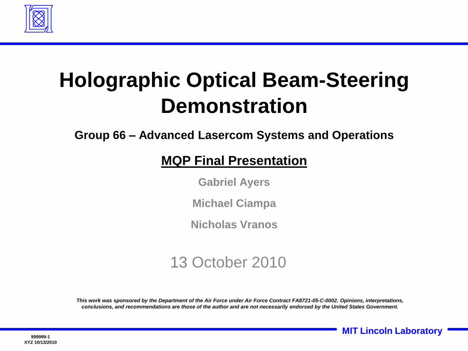
Beam Steering Applications
• Free-space laser communications ("lasercom")
– High Bandwidth
– High Security
– Point to Point laser communication
• Infrared Countermeasures
– Possibly used to ‘blind’ sensors of airborne projectiles
• Laser Radar

MIT Lincoln Laboratory999999-4
XYZ 10/13/2010
Beam Steering Examples
Gimbaled Mirrors Risley Prisms
BAE Systems Agile Eye
Infrared Countermeasure
Optra 2” diameter clear
aperture compact beam
steering system

MIT Lincoln Laboratory999999-5
XYZ 10/13/2010
• Conformal intrudes less into an aircraft’s air stream
– Less impact to flight dynamics
– Less drag induced to aircraft
– Less optical distortions to beam
Conformal vs. Nonconformal Beam Directors
BeamDirector
Optical module
Window Interface
Beam Director
Optical module
Turret Interface
MIT Lincoln Laboratory999999-6
XYZ 10/13/2010
Holographic Optical Diffraction Gratings
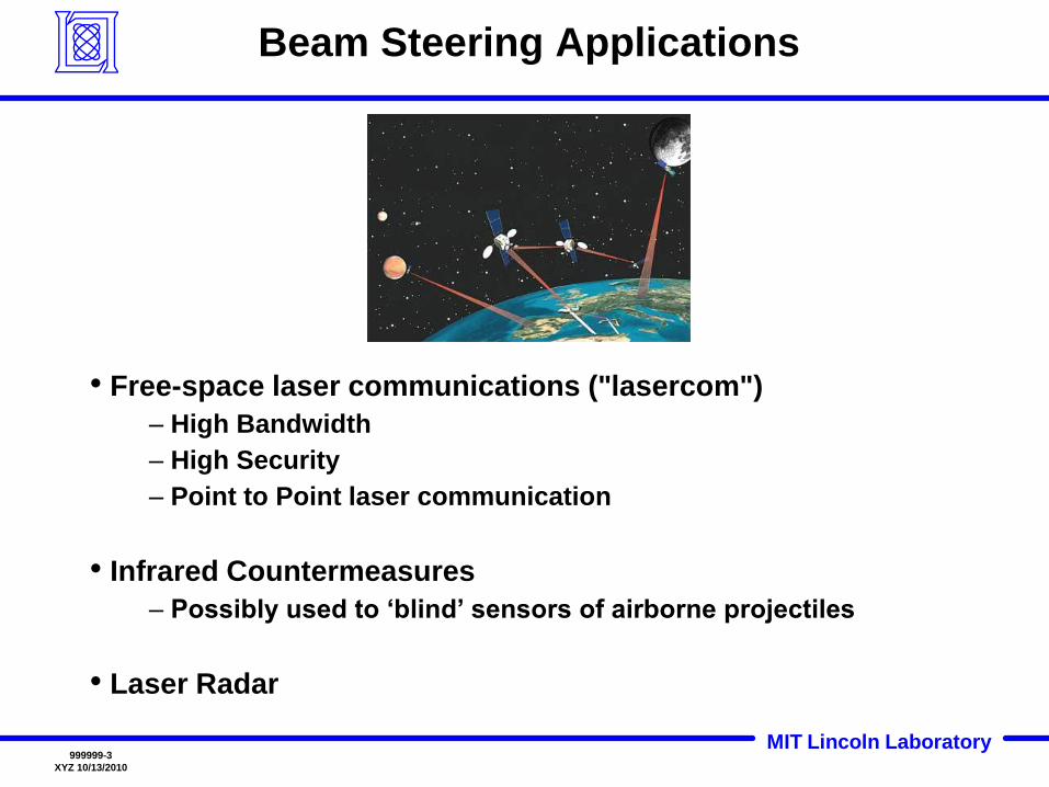
What is a Holographic Optical Diffraction Grating?
In each optical element there is a periodic structure, which modulates the refractive index. This structure uses Bragg diffraction to deflect the beam.
Properties:
• Reflection or Transmission mode
• Multi-Wavelength
• High Efficiency
• High Power
• Thermally Stable
HOBS Gratings:
• Square 50 mm
• Blazed for two wavelengths
• Transmission Mode
MIT Lincoln Laboratory999999-7
XYZ 10/13/2010
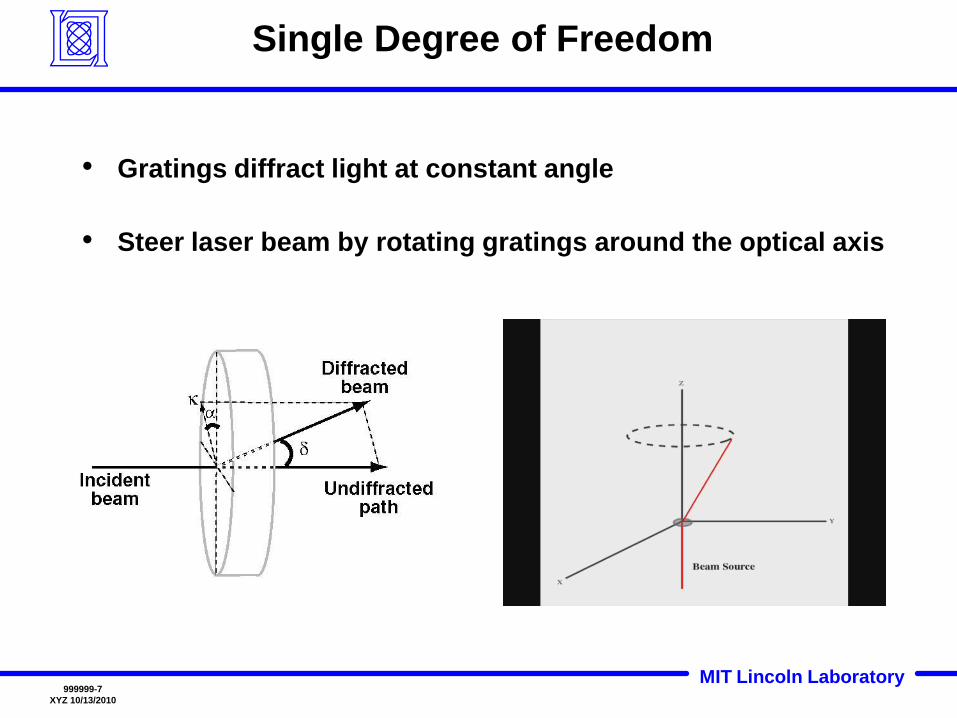
Single Degree of Freedom
• Gratings diffract light at constant angle
• Steer laser beam by rotating gratings around the optical axis
MIT Lincoln Laboratory999999-8
XYZ 10/13/2010
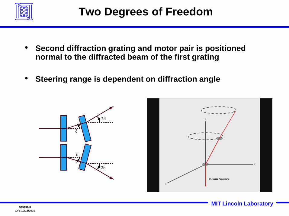
Two Degrees of Freedom
• Second diffraction grating and motor pair is positioned normal to the diffracted beam of the first grating
• Steering range is dependent on diffraction angle

MIT Lincoln Laboratory999999-9
XYZ 10/13/2010
HOBS Goal
• Construct a Holographic Optical Beam-Steering
(HOBS) prototype capable of steering two
wavelengths to transmit and receive
• Develop a steering algorithm
• Characterize the optical properties of the system
• Deliver a prototype demonstration and evaluation
to Lincoln Laboratory
MIT Lincoln Laboratory999999-10
XYZ 10/13/2010
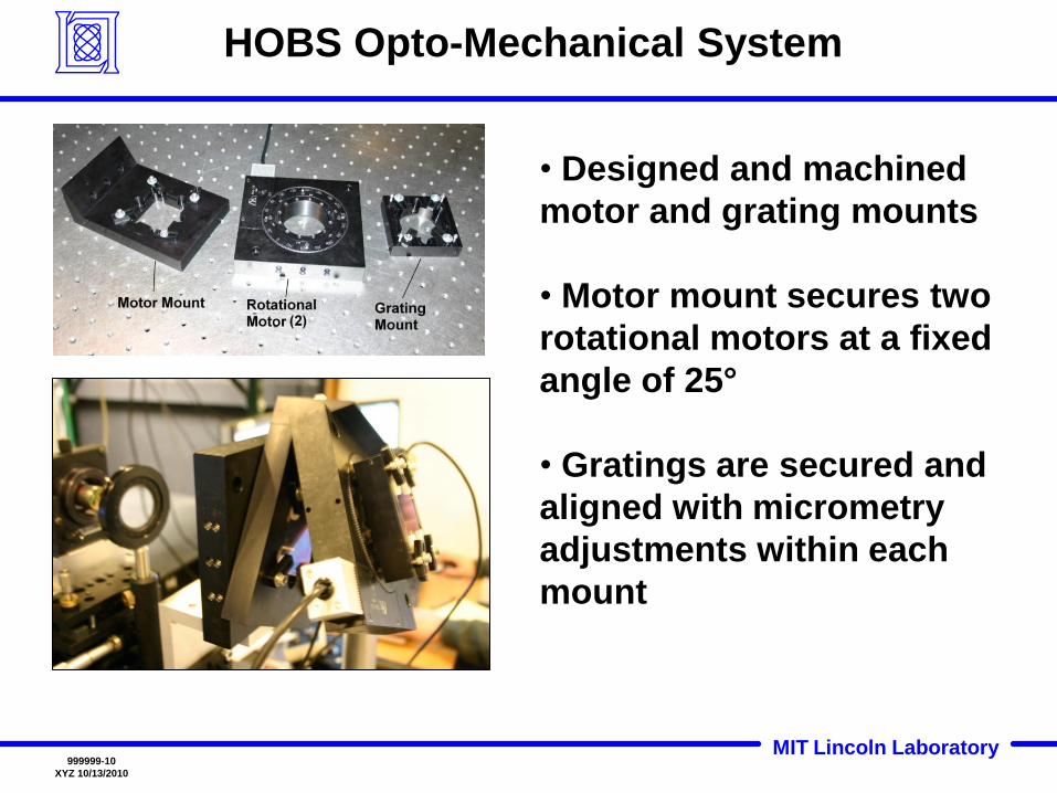
HOBS Opto-Mechanical System
• Designed and machined
motor and grating mounts
• Motor mount secures two
rotational motors at a fixed
angle of 25°
• Gratings are secured and
aligned with micrometry
adjustments within each
mount
MIT Lincoln Laboratory999999-11
XYZ 10/13/2010
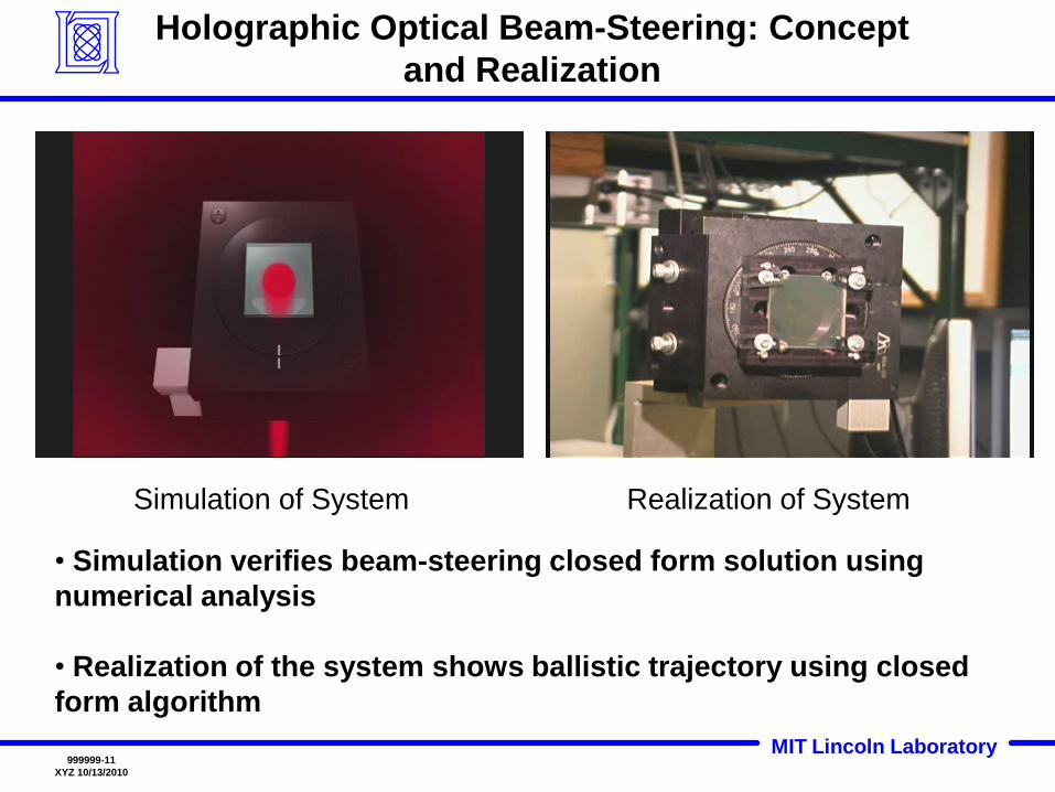
Holographic Optical Beam-Steering: Concept
and Realization
• Simulation verifies beam-steering closed form solution using
numerical analysis
• Realization of the system shows ballistic trajectory using closed
form algorithm
Realization of SystemSimulation of System
MIT Lincoln Laboratory999999-12
XYZ 10/13/2010
Optical Characterizationof Holographic Diffraction Gratings
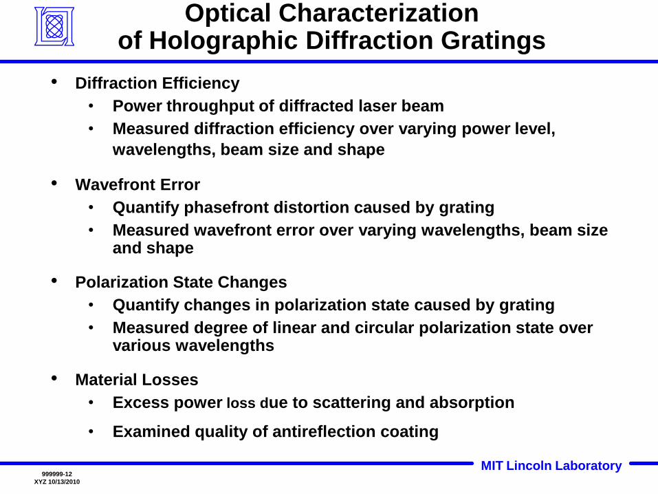
• Diffraction Efficiency
• Power throughput of diffracted laser beam
• Measured diffraction efficiency over varying power level,
wavelengths, beam size and shape
• Wavefront Error
• Quantify phasefront distortion caused by grating
• Measured wavefront error over varying wavelengths, beam size and shape
• Polarization State Changes
• Quantify changes in polarization state caused by grating
• Measured degree of linear and circular polarization state over various wavelengths
• Material Losses
• Excess power loss due to scattering and absorption
• Examined quality of antireflection coating
MIT Lincoln Laboratory999999-13
XYZ 10/13/2010
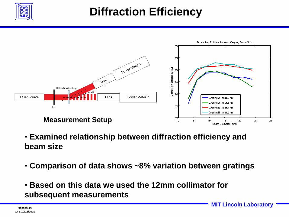
Diffraction Efficiency
• Examined relationship between diffraction efficiency and
beam size
• Comparison of data shows ~8% variation between gratings
• Based on this data we used the 12mm collimator for
subsequent measurements
Measurement Setup

MIT Lincoln Laboratory999999-14
XYZ 10/13/2010
Wavefront Error
Wavelength: 1544.5 nm
Effect on phase front of incident beam traveling through diffraction
gratings
MIT Lincoln Laboratory999999-15
XYZ 10/13/2010
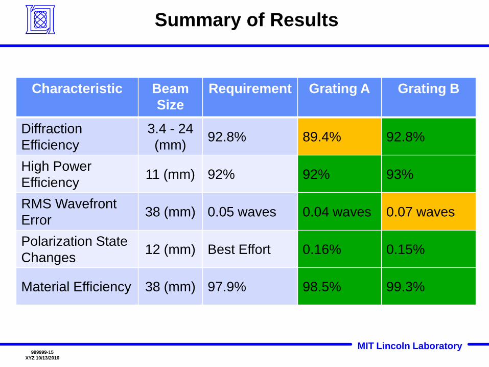
Summary of Results
Characteristic Beam
Size
Requirement Grating A Grating B
Diffraction
Efficiency
3.4 - 24
(mm)92.8% 89.4% 92.8%
High Power
Efficiency11 (mm) 92% 92% 93%
RMS Wavefront
Error38 (mm) 0.05 waves 0.04 waves 0.07 waves
Polarization State
Changes12 (mm) Best Effort 0.16% 0.15%
Material Efficiency 38 (mm) 97.9% 98.5% 99.3%

MIT Lincoln Laboratory999999-16
XYZ 10/13/2010
Scan Pattern Simulation
• Demonstrated with a green laser for
visualization purposes
• Scan patterns are often used in applications
such as lasercom to find a target terminal
MIT Lincoln Laboratory999999-17
XYZ 10/13/2010
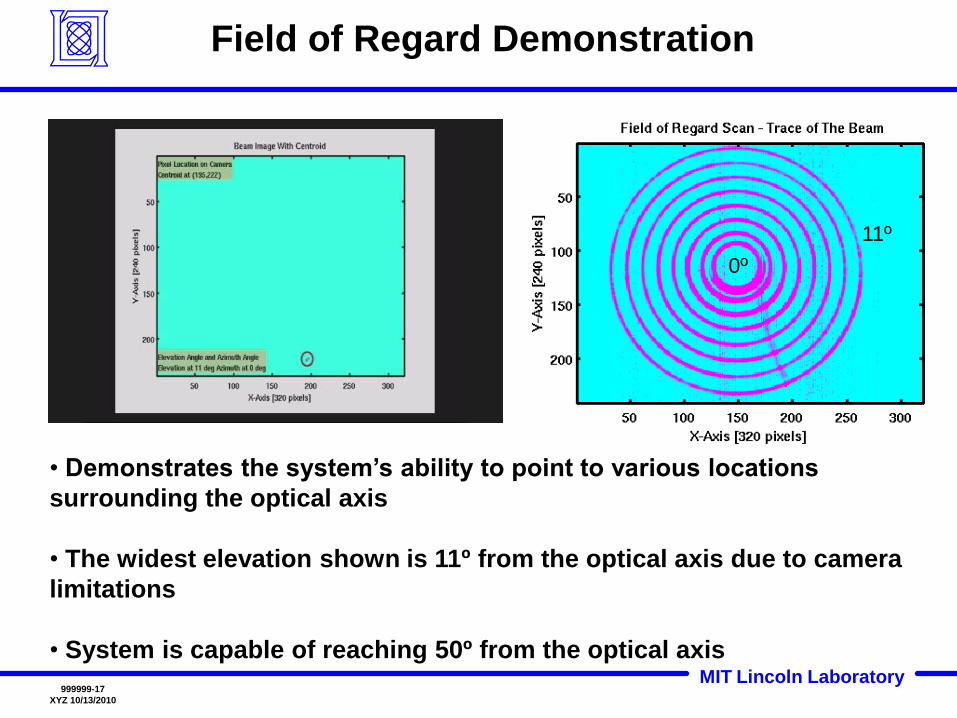
Field of Regard Demonstration
• Demonstrates the system’s ability to point to various locations
surrounding the optical axis
• The widest elevation shown is 11º from the optical axis due to camera
limitations
• System is capable of reaching 50º from the optical axis
11º
0º

MIT Lincoln Laboratory999999-18
XYZ 10/13/2010
High Resolution Precision Demonstration
• The two points are separated by 1680 μrad
• Camera has an angular resolution of approximately 50 μrad per
pixel
• Demonstrates the system’s ability to precisely point to a location
on a small angle scale
MIT Lincoln Laboratory999999-19
XYZ 10/13/2010
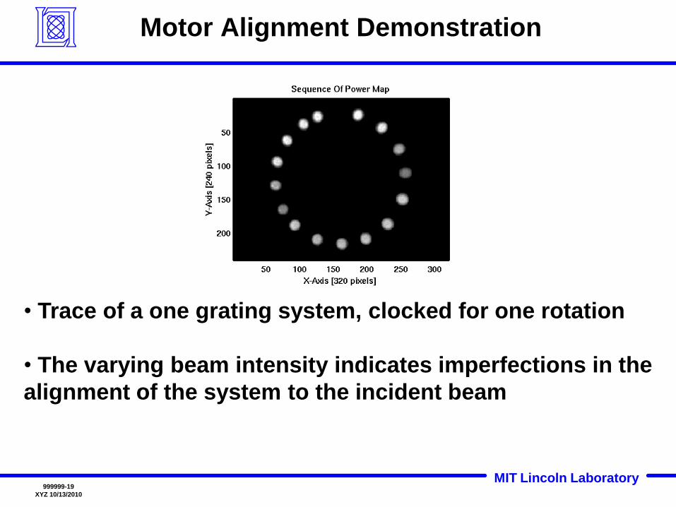
Motor Alignment Demonstration
• Trace of a one grating system, clocked for one rotation
• The varying beam intensity indicates imperfections in the
alignment of the system to the incident beam

MIT Lincoln Laboratory999999-20
XYZ 10/13/2010
Diffraction Angle Wavelength Dependence Demonstration
• Demonstrates how the diffraction angle of the incident beam varies
with wavelength
• There is a boresight misalignment between the two wavelengths of
175 μrad
λ = 1544.5 nm
nmλ = 1564.5 nm
MIT Lincoln Laboratory999999-21
XYZ 10/13/2010
Summary
• We have presented a semi-conformal method of beam steering using 50 mm holographic diffraction gratings
• The optical characterization and system pointing tests show that the HOBS approach holds promise for future beam steering systems
• Limitations
Boresight misalignment between wavelengths
Inability to accurately align mechanical system
• Future work
Determine tolerance of alignment to incident beam
Redesign mechanical mounting system
Characterize thermal stability
MIT Lincoln Laboratory999999-22
XYZ 10/13/2010
Acknowledgements
Jeffrey M. Roth
Timothy H. Williams
Edward A. Clancy
Steven Michael
William E. Wilcox
George A. Nowak
Patrick T. Cable
Special Thanks to:
Group 66
Recommended