8/6/2019 How Not to Design an Avionics System
http://slidepdf.com/reader/full/how-not-to-design-an-avionics-system 1/20
3rd Responsive Space Conference
April 25–28, 2005 Los Angeles, CA
HOW NOT TO DESIGN
AN AVIONICS SYSTEM
Jason E. Holt
Brigham Young UniversityProvo, UT
3rd Responsive Space Conference
RS3-2005-5006
8/6/2019 How Not to Design an Avionics System
http://slidepdf.com/reader/full/how-not-to-design-an-avionics-system 2/20
2005-5006
HOW NOT TO DESIGN AN AVIONICS SYSTEM
Jason E. Holt [email protected]
April 8, 2005
Abstract
In 1995, four Utah Universities launched a hy-
brid sounding rocket at the Utah Test and Train-
ing Range. In December 2003, they success-
fully launched a much larger successor to that
rocket. We describe the design, construction,
deconstruction, redesign and reconstruction of
the avionics package during the 8 year period
between flights, then describe the system whichwas actually flown. That package used COTS
hardware worth less than $1000, was substan-
tially redesigned within weeks of the launch,
and was completely destroyed after an entirely
successful flight upon an otherwise soft, verti-
cal landing. Although the package met only
simple requirements and used no cutting-edge
hardware, we feel that the lessons we learned
from both technical and social standpoints will
be useful to others who wish to rapidly de-velop avionics systems despite severely limited
resources. Furthermore, we describe a new,
straightforward design for the core control sys-
tem which is a result of the lessons we learned,
Copyright c2005 Jason E. Holt. Published by AIAA
3rd Responsive Space Conference 2005 with permission.
and which we hope will be flexible enough to
meet the continuing demands of our project andpotentially many other projects as well.
1 Introduction
As a collaboration between universities, the
Unity IV project tasked university students with
designing, building and flying a hybrid sounding
rocket capable of reaching 100,000 feet AGL. In
each of the last two launch attempts, the avion-
ics team worked with limited funds, manpower,time and experience to rapidly respond to chang-
ing system needs and ready a launch-worthy
system with only a few man-weeks of available
effort.
In the next section, we give a brief overview
of the system requirements for a rocket like
Unity IV. In section 3, we detail the development
of the avionics system during a period stretch-
ing 1995 to 2003, but during which most of the
development happened in two periods of sev-eral weeks. The following section describes the
work currently underway to generalize the solu-
tions developed over the course of the project. In
both sections, we highlight the occasions which
relate to the five overarching design principles
we have identified. Each of these principles is
1
AIAA-3rd Responsive Space Conference 2005
8/6/2019 How Not to Design an Avionics System
http://slidepdf.com/reader/full/how-not-to-design-an-avionics-system 3/20
directly related to the task of developing respon-
sive systems. We discuss each principle in detail
in section 5.
2 System Requirements
The onboard avionics system for an unguided
rocket like ours need not be very complex. Per-
haps the only critical feature is deployment of
the recovery parachute, and hobby store model
rockets don’t even use electronics for this task.
Firing the ignition system and opening the ox-
idizer tank can potentially be done using a
ground-based system which detaches at launch,
but this has pitfalls which make it more suitedfor the onboard system.
Secondary requirements include radio-
controlled launch, abort and recovery actuation,
video downlink, and data capture and telemetry
for aspects of the flight such as tank and ignition
chamber pressure, battery voltage and altitude.
Since the recovery parachute system is so crit-
ical to a successful flight, deployment criteria
must be designed and implemented very care-
fully. Failure to deploy the parachute is obvi-ously disastrous, but so is deployment while the
motor is firing, and, as we learned, deployment
on the launch rail poses a hazard to personnel.
3 Project History
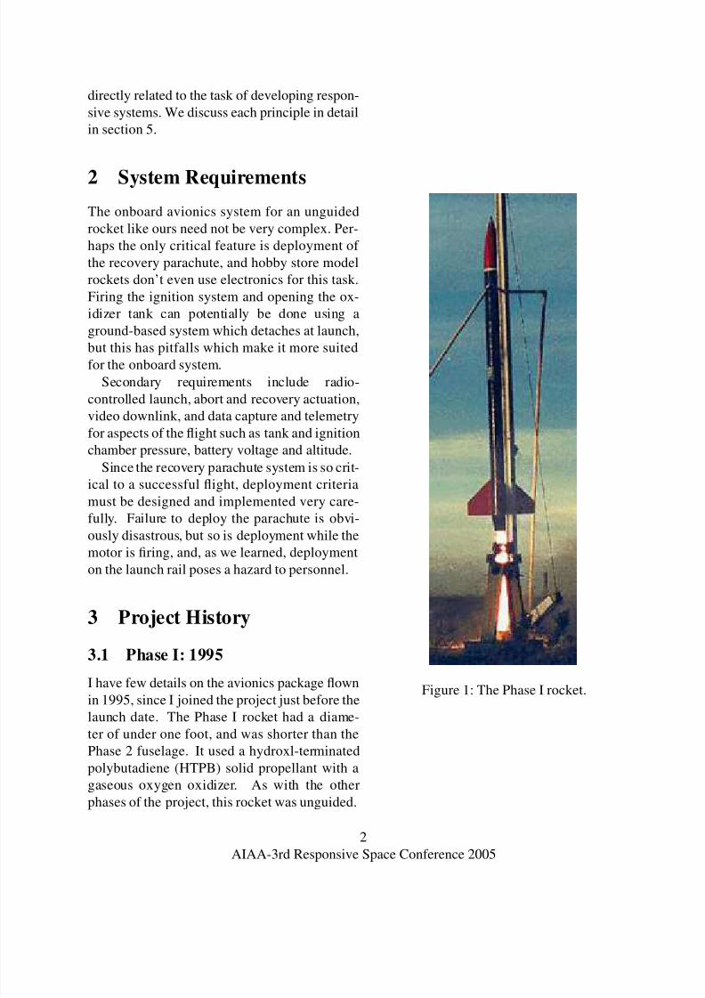
3.1 Phase I: 1995
I have few details on the avionics package flown
in 1995, since I joined the project just before thelaunch date. The Phase I rocket had a diame-
ter of under one foot, and was shorter than the
Phase 2 fuselage. It used a hydroxl-terminated
polybutadiene (HTPB) solid propellant with a
gaseous oxygen oxidizer. As with the other
phases of the project, this rocket was unguided.
Figure 1: The Phase I rocket.
2
AIAA-3rd Responsive Space Conference 2005

8/6/2019 How Not to Design an Avionics System
http://slidepdf.com/reader/full/how-not-to-design-an-avionics-system 4/20
Based on my recollection, the Phase I rocket
used an electromechanical actuator connected to
the launch rail to open the oxidizer tank and
an external igniter battery which disconnected
from the fuselage at launch. Thus, the onboard
avionics system only had to eject the nosecone
and deploy the recovery parachute after reach-
ing apogee.
Explosive bolts attached the nosecone to the
fuselage. The nosecone drew out a drogue
parachute used to draw out the main parachute,
which was later released using a separate actu-
ator. A pressure transducer indicated altitude.
When atmospheric pressure stopped decreasing
and started rising again, the system assumed
apogee was reached and deployed the recoverysystem. The system also had a radio override
which would eject the nosecone, wait several
seconds, then deploy the main parachute.
The launch crew stayed in a concrete bunker
near the launch site for the duration of the flight,
while the less critical team members were sent
several miles away, outside the maximum foot-
print of the rocket flightpath, to watch. The
launch crew had a video camera aimed at the
launch pad, but had no view of the flight oncethe rocket left the launch rail.
In the first launch attempt, the igniters failed
and the launch crew had to wait until the ox-
idizer dissipated before refilling the oxidizer
tank. On the second attempt, the motor worked
properly and the rocket ascended to an apogee of
around 4,500 feet AGL. Since I was not part of
the launch crew, I remember seeing the barely-
visible rocket ascend to apogee, then gently nose
over and head almost straight down. The ra-dio operator with our team radioed that apogee
was reached, then said, “No chute! No chute!”
as we saw that no parachute was deploying.
The launch operator signalled the override un-
til our radio operator reported that the drogue
parachute had opened, and once the launch op-
erator stopped signalling an override, the sys-
tem initiated its delay before cutting the main
parachute loose. Unfortunately, the rocket im-
pacted before the delay expired, and the fuselage
was destroyed.
The lesson we should have learned at that
point is that prototype systems need to be re-
sponsive to human intervention. Responsive-
ness means that we won’t always have time to
thoroughly test, or even predict, every possible
contingency. Consequently, when unforseen cir-
cumstances arrive, quick-thinking humans may
be able to avert disaster if the system allows
them enough flexibility to do so. Unfortunately,
it took two other failures for us to learn that
fine-grained manual overrides can prevent costlydamage to vehicle components.
3.2 Interim
We took the crash as an opportunity to redesign
the launch vehicle. As a new member of the
project and one of only a few people working
on the avionics package, I spent many enjoyable
evenings considering the many interesting fea-
tures an avionics system might provide the vehi-cle. A wide array of sensors could collect data
which might conceivably be useful to the motor
and flight vehicle team. GPS, accelerometers,
pitot tubes, altitude sensors, magnetometers, ra-
dio and computer vision systems might all be
used in measuring the flight path and detecting
apogee. Our platform is designed so that it can
eventually reach 100,000 feet and travel at su-
personic speeds, so I did research into GPS units
which would function at higher-than-normal al-titudes and velocities. Video downlink would
also be a huge bonus, and digital video could
have higher quality than an analog signal.
With such visions in mind, I requested fund-
ing for a prototyping board based on the Mo-
torola 68HC11 microcontroller, since it would
3
AIAA-3rd Responsive Space Conference 2005
8/6/2019 How Not to Design an Avionics System
http://slidepdf.com/reader/full/how-not-to-design-an-avionics-system 5/20
have enough serial ports to handle both the radio
uplink/downlink and GPS. Since I was taking an
operating systems class, I took the opportunity
to write a general purpose state machine inter-
face in C as a class project. Without close in-
volvement with the other people working on the
project or experienced mentors, I got little fur-
ther work done, and in 1997 I left my university
studies for other pursuits. Neither the board nor
the code were ever used. In retrospect, I failed
to do the simplest thing that could possibly
work and didn’t yet see the need to remember
psychology.
Apparently, intervening avionics teams made
some of the same mistakes I had. When I again
became involved in the project, there still hadbeen no launches, but we had accumulated sev-
eral other microcontrollers and miscellaneous
gadgetry, including several LCD displays which
have never, as far as I can tell, been used for
anything.
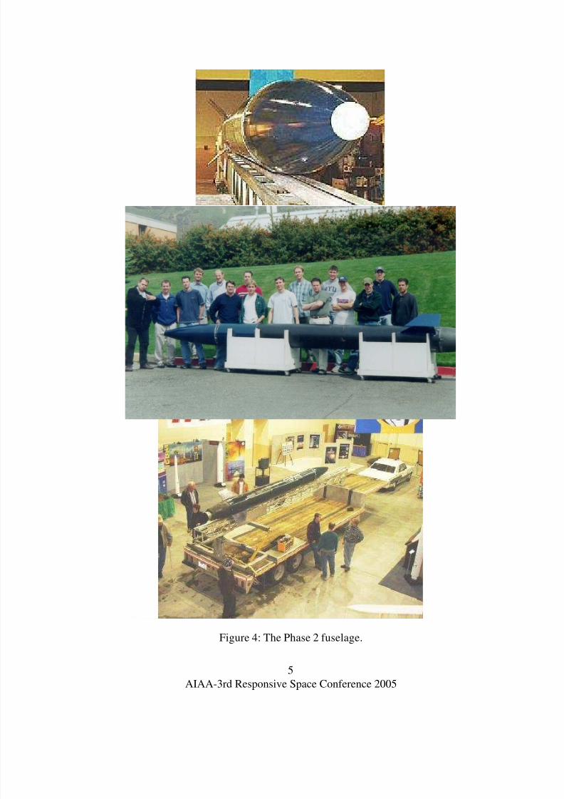
The other teams had also been hard at work.
The launch vehicle was much larger, 17 inches
in diameter and standing over twenty feet tall,
custom built from carbon fiber (figures 3 and
4). A more powerful engine could theoreti-cally lift the vehicle to our target of 100,000
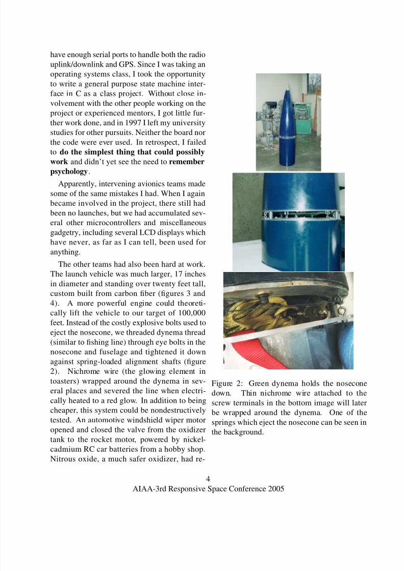
feet. Instead of the costly explosive bolts used to
eject the nosecone, we threaded dynema thread
(similar to fishing line) through eye bolts in the
nosecone and fuselage and tightened it down
against spring-loaded alignment shafts (figure
2). Nichrome wire (the glowing element in
toasters) wrapped around the dynema in sev-
eral places and severed the line when electri-
cally heated to a red glow. In addition to beingcheaper, this system could be nondestructively
tested. An automotive windshield wiper motor
opened and closed the valve from the oxidizer
tank to the rocket motor, powered by nickel-
cadmium RC car batteries from a hobby shop.
Nitrous oxide, a much safer oxidizer, had re-
Figure 2: Green dynema holds the nosecone
down. Thin nichrome wire attached to the
screw terminals in the bottom image will laterbe wrapped around the dynema. One of the
springs which eject the nosecone can be seen in
the background.
4
AIAA-3rd Responsive Space Conference 2005
8/6/2019 How Not to Design an Avionics System
http://slidepdf.com/reader/full/how-not-to-design-an-avionics-system 6/20
Figure 4: The Phase 2 fuselage.
5
AIAA-3rd Responsive Space Conference 2005
8/6/2019 How Not to Design an Avionics System
http://slidepdf.com/reader/full/how-not-to-design-an-avionics-system 7/20
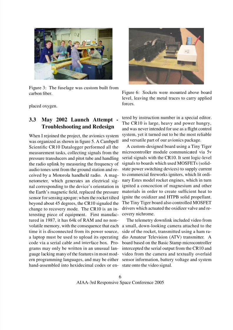
Figure 3: The fuselage was custom built from
carbon fiber.
placed oxygen.
3.3 May 2002 Launch Attempt -
Troubleshooting and Redesign
When I rejoined the project, the avionics system
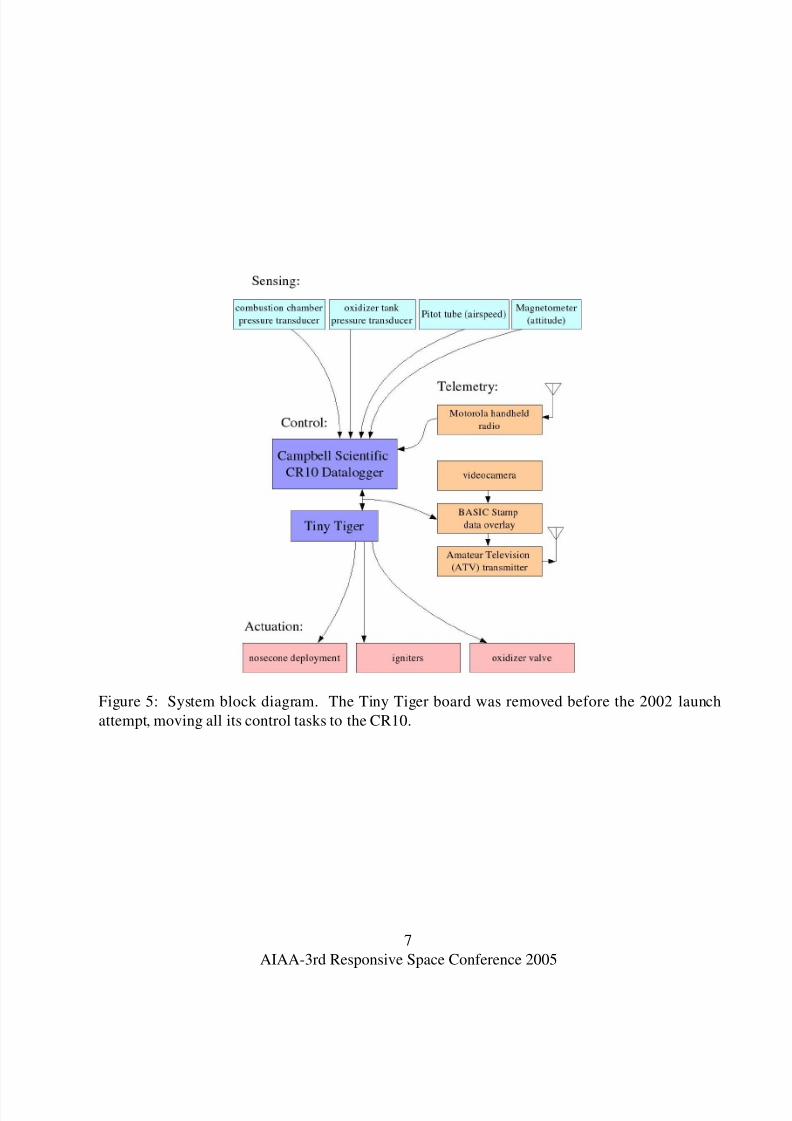
was organized as shown in figure 5. A Cambpell
Scientific CR10 Datalogger performed all the
measurement tasks, collecting signals from the
pressure transducers and pitot tube and handling
the radio uplink by measuring the frequency of
audio tones sent from the ground station and re-
ceived by a Motorola handheld radio. A mag-netometer, which generates an electrical sig-
nal corresponding to the device’s orientation in
the Earth’s magnetic field, replaced the pressure
sensor for sensing apogee; when the rocket tilted
beyond about 45 degrees, the CR10 signaled the
change to recovery mode. The CR10 is an in-
teresting piece of equipment. First manufac-
tured in 1987, it has 64k of RAM and no non-
volatile memory, with the consequence that each
time it is disconnected from its power source,a laptop must be used to upload its operating
code via a serial cable and interface box. Pro-
grams may only be written in an unusual lan-
guage lacking many of the features in most mod-
ern programming languages, and may be either
hand-assembled into hexidecimal codes or en-
Figure 6: Sockets were mounted above board
level, leaving the metal traces to carry applied
forces.
tered by instruction number in a special editor.
The CR10 is large, heavy and power hungry,
and was never intended for use as a flight control
system, yet it turned out to be the most reliable
and versatile part of our avionics package.
A custom-designed board using a Tiny Tiger
microcontroller module communicated via 5v
serial signals with the CR10. It sent logic-level
signals to boards which used MOSFETs (solid-
state power switching devices) to supply current
to commercial fireworks igniters, which lit ordi-nary Estes model rocket engines, which in turn
ignited a concoction of magnesium and other
materials in order to create sufficient heat to
ignite the oxidizer and HTPB solid propellant.
The Tiny Tiger board also controlled MOSFET
drivers which actuated the oxidizer valve and re-
covery nichrome.
The telemetry downlink included video from
a small, down-looking camera attached to the
side of the rocket, transmitted using a ham ra-dio Amateur Television (ATV) transmitter. A
board based on the Basic Stamp microcontroller
intercepted the serial output from the CR10 and
video from the camera and textually overlaid
sensor information, battery voltage and system
state onto the video signal.
6
AIAA-3rd Responsive Space Conference 2005
8/6/2019 How Not to Design an Avionics System
http://slidepdf.com/reader/full/how-not-to-design-an-avionics-system 8/20
Figure 5: System block diagram. The Tiny Tiger board was removed before the 2002 launch
attempt, moving all its control tasks to the CR10.
7
AIAA-3rd Responsive Space Conference 2005
8/6/2019 How Not to Design an Avionics System
http://slidepdf.com/reader/full/how-not-to-design-an-avionics-system 9/20
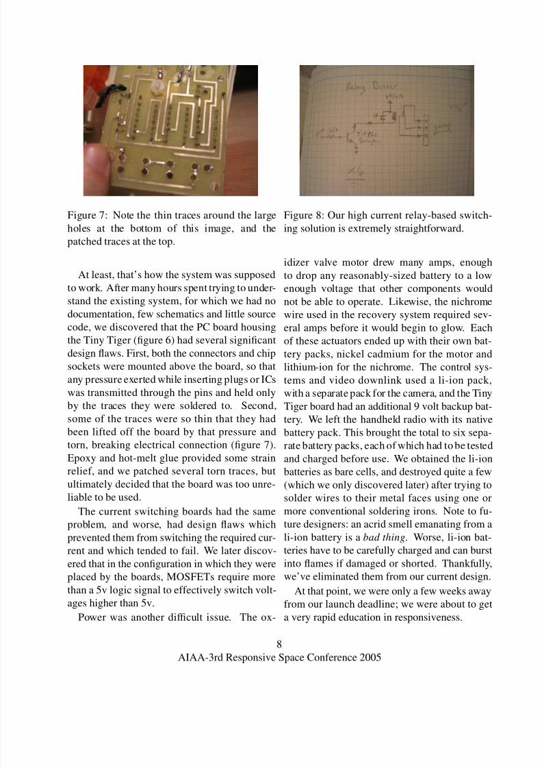
Figure 7: Note the thin traces around the large
holes at the bottom of this image, and the
patched traces at the top.
At least, that’s how the system was supposed
to work. After many hours spent trying to under-
stand the existing system, for which we had no
documentation, few schematics and little source
code, we discovered that the PC board housing
the Tiny Tiger (figure 6) had several significant
design flaws. First, both the connectors and chip
sockets were mounted above the board, so that
any pressure exerted while inserting plugs or ICs
was transmitted through the pins and held only
by the traces they were soldered to. Second,some of the traces were so thin that they had
been lifted off the board by that pressure and
torn, breaking electrical connection (figure 7).
Epoxy and hot-melt glue provided some strain
relief, and we patched several torn traces, but
ultimately decided that the board was too unre-
liable to be used.
The current switching boards had the same
problem, and worse, had design flaws which
prevented them from switching the required cur-rent and which tended to fail. We later discov-
ered that in the configuration in which they were
placed by the boards, MOSFETs require more
than a 5v logic signal to effectively switch volt-
ages higher than 5v.
Power was another difficult issue. The ox-
Figure 8: Our high current relay-based switch-
ing solution is extremely straightforward.
idizer valve motor drew many amps, enough
to drop any reasonably-sized battery to a low
enough voltage that other components would
not be able to operate. Likewise, the nichrome
wire used in the recovery system required sev-
eral amps before it would begin to glow. Each
of these actuators ended up with their own bat-
tery packs, nickel cadmium for the motor and
lithium-ion for the nichrome. The control sys-
tems and video downlink used a li-ion pack,
with a separate pack for the camera, and the Tiny
Tiger board had an additional 9 volt backup bat-tery. We left the handheld radio with its native
battery pack. This brought the total to six sepa-
rate battery packs, each of which had to be tested
and charged before use. We obtained the li-ion
batteries as bare cells, and destroyed quite a few
(which we only discovered later) after trying to
solder wires to their metal faces using one or
more conventional soldering irons. Note to fu-
ture designers: an acrid smell emanating from a
li-ion battery is a bad thing. Worse, li-ion bat-teries have to be carefully charged and can burst
into flames if damaged or shorted. Thankfully,
we’ve eliminated them from our current design.
At that point, we were only a few weeks away
from our launch deadline; we were about to get
a very rapid education in responsiveness.
8
AIAA-3rd Responsive Space Conference 2005
8/6/2019 How Not to Design an Avionics System
http://slidepdf.com/reader/full/how-not-to-design-an-avionics-system 10/20
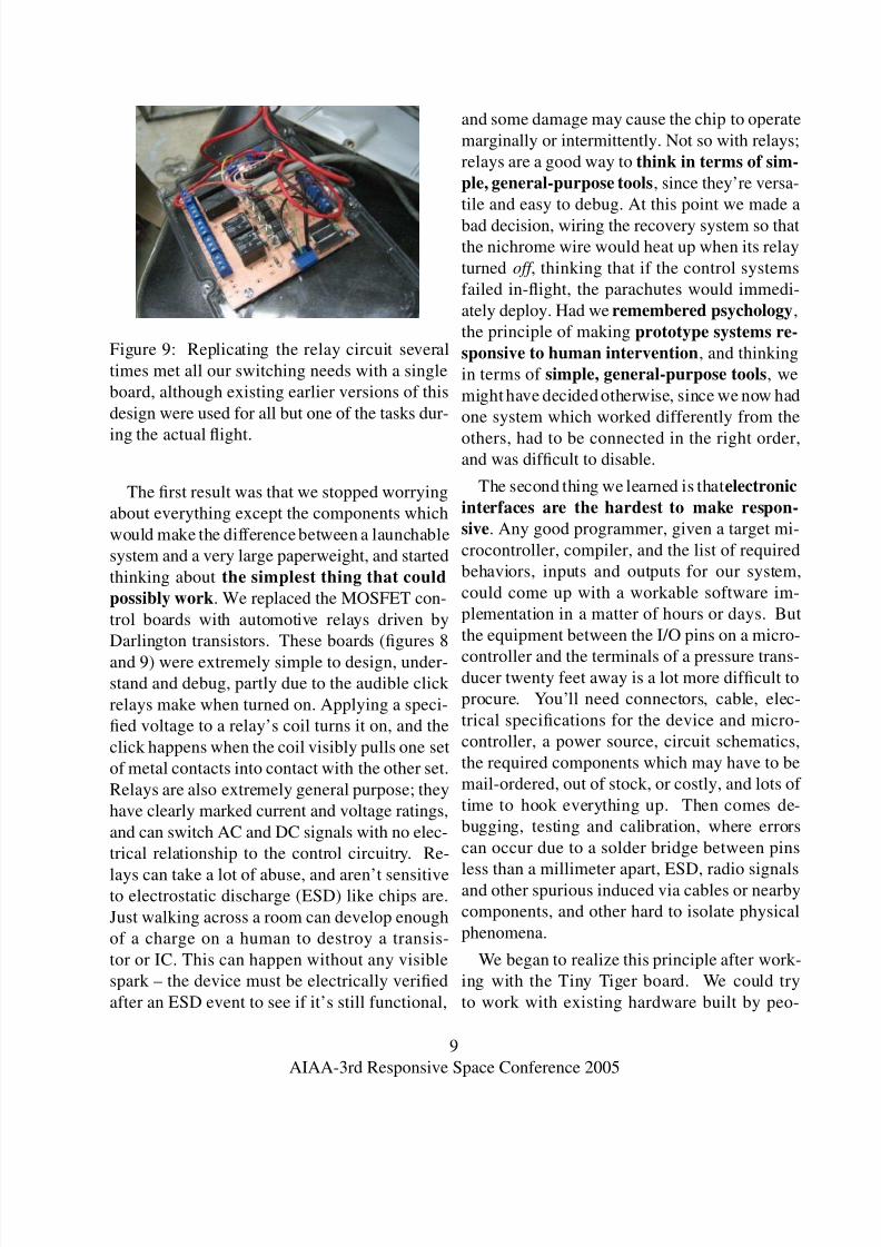
Figure 9: Replicating the relay circuit several
times met all our switching needs with a single
board, although existing earlier versions of this
design were used for all but one of the tasks dur-
ing the actual flight.
The first result was that we stopped worrying
about everything except the components which
would make the difference between a launchable
system and a very large paperweight, and started
thinking about the simplest thing that could
possibly work. We replaced the MOSFET con-
trol boards with automotive relays driven by
Darlington transistors. These boards (figures 8
and 9) were extremely simple to design, under-stand and debug, partly due to the audible click
relays make when turned on. Applying a speci-
fied voltage to a relay’s coil turns it on, and the
click happens when the coil visibly pulls one set
of metal contacts into contact with the other set.
Relays are also extremely general purpose; they
have clearly marked current and voltage ratings,
and can switch AC and DC signals with no elec-
trical relationship to the control circuitry. Re-
lays can take a lot of abuse, and aren’t sensitiveto electrostatic discharge (ESD) like chips are.
Just walking across a room can develop enough
of a charge on a human to destroy a transis-
tor or IC. This can happen without any visible
spark – the device must be electrically verified
after an ESD event to see if it’s still functional,
and some damage may cause the chip to operate
marginally or intermittently. Not so with relays;
relays are a good way to think in terms of sim-
ple, general-purpose tools, since they’re versa-
tile and easy to debug. At this point we made a
bad decision, wiring the recovery system so that
the nichrome wire would heat up when its relay
turned off , thinking that if the control systems
failed in-flight, the parachutes would immedi-
ately deploy. Had we remembered psychology,
the principle of making prototype systems re-
sponsive to human intervention, and thinking
in terms of simple, general-purpose tools, we
might have decided otherwise, since we now had
one system which worked differently from the
others, had to be connected in the right order,and was difficult to disable.
The second thing we learned is that electronic
interfaces are the hardest to make respon-
sive. Any good programmer, given a target mi-
crocontroller, compiler, and the list of required
behaviors, inputs and outputs for our system,
could come up with a workable software im-
plementation in a matter of hours or days. But
the equipment between the I/O pins on a micro-
controller and the terminals of a pressure trans-ducer twenty feet away is a lot more difficult to
procure. You’ll need connectors, cable, elec-
trical specifications for the device and micro-
controller, a power source, circuit schematics,
the required components which may have to be
mail-ordered, out of stock, or costly, and lots of
time to hook everything up. Then comes de-
bugging, testing and calibration, where errors
can occur due to a solder bridge between pins
less than a millimeter apart, ESD, radio signalsand other spurious induced via cables or nearby
components, and other hard to isolate physical
phenomena.
We began to realize this principle after work-
ing with the Tiny Tiger board. We could try
to work with existing hardware built by peo-
9
AIAA-3rd Responsive Space Conference 2005
8/6/2019 How Not to Design an Avionics System
http://slidepdf.com/reader/full/how-not-to-design-an-avionics-system 11/20
ple with experience and time for testing as lim-
ited as our own, design and build new compo-
nents which would need to be debugged and
tested, or try to find commercial off-the-shelf
(COTS) products which would meet our needs.
That’s when we started looking seriously at the
CR10 datalogger, which had been on the mar-
ket for over ten years and had been designed
and tested specifically for use in harsh condi-
tions by people with limited electronics experi-
ence. The CR10 had calibrated analog inputs ca-
pable of measuring the small signals created by
the pressure transducers and magnetometer. It
had enough logic-level outputs to drive the ac-
tuators in our system, was internally protected
against ESD, had screw terminals for all exter-nal connections, making it easy to disconnect,
reconfigure and test the peripheral devices, and
had a programming interface which, though ar-
cane, was at least clearly documented. Making
it the center of our avionics system was one of
the best decisions we made. Figure 10 shows the
control and telemetry portions of the package.
We rewrote the CR10 code to include all
the tasks the Tiny Tiger board had been per-
forming, hand-wired the relay boards and fin-ished the battery packs, working all night be-
fore the everything-but-oxidizer system test at
BYU. With the other teams waiting for us to fin-
ish wiring and testing the components, someone
smelled smoke and noticed that the nichrome
wires were glowing red and burning the surfaces
they rested on – someone had cut a power cable
in preparation for rewiring, and in the process
momentarily shorted out the power supply feed-
ing the CR10. Momentarily without power, itlost its program and reset all its outputs, includ-
ing the output driving the relay board controlling
the nichrome.
Miraculously, the system worked well enough
to get us through the test, although we realized
toward the end of the test that the batteries had
become dangerously low. We pushed on, and
the test was successful. However, before we
could lower the rocket back to a horizontal posi-
tion on the launch rail, the batteries finally gave
out, and once again the recovery failsafe acti-
vated, dropping the nosecone to the ground and
damaging its body and the pitot tube. Fortu-
nately, none of the personnel were hit, and we
added an operational rule requiring hard hats
when working near the powered system.
At the launch, we again set up the system,
with a repaired nosecone and carefully charged
battery that we didn’t plug in until we had to.
This began the excruciating process of watch-
ing the battery voltage slowly descend as all theother necessary launch tasks took place, the per-
sonnel were collected into their assigned places,
and the planned hold had completed. When we
pressed the launch button, I was frankly a little
surprised to see the igniters fire and flames bil-
low out from the bottom of the rocket. However,
the rocket never lifted off the pad. We observed
that the oxidizer tank pressure was descending
more slowly than it ought, and considered ac-
tivating the abort sequence which would have
closed the oxidizer valve. However, the abortsequence also would have ejected the nosecone,
pulling the drogue parachute with it as it fell
into the cloud of smoke and flame at the base
of the rocket. We opted to let the tank empty
itself out, and 45 seconds later were left with
a burning launch trailer and singed rocket. Fi-
nally, the principle of making prototype sys-
tems responsive to human intervention sunk
in, but now we were left with a rocket convinced
it was sailing through the atmosphere, with onlytwo possible futures. It could either receive
the abort signal from our ground station, or tilt
over enough to trip the magnetometer. In either
case, it would shut the oxidizer valve, destroying
any evidence of failure caused by a partly-open
valve, and eject the nosecone and parachute to a
10
AIAA-3rd Responsive Space Conference 2005
8/6/2019 How Not to Design an Avionics System
http://slidepdf.com/reader/full/how-not-to-design-an-avionics-system 12/20
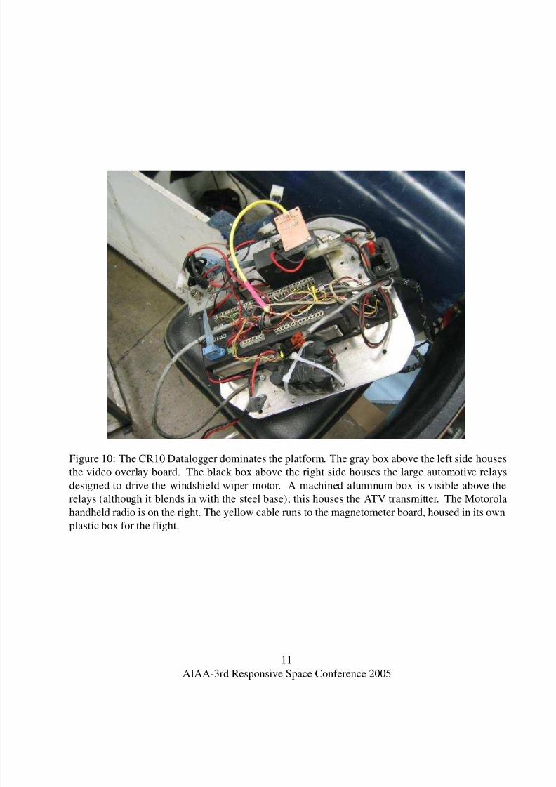
Figure 10: The CR10 Datalogger dominates the platform. The gray box above the left side houses
the video overlay board. The black box above the right side houses the large automotive relays
designed to drive the windshield wiper motor. A machined aluminum box is visible above the
relays (although it blends in with the steel base); this houses the ATV transmitter. The Motorola
handheld radio is on the right. The yellow cable runs to the magnetometer board, housed in its own
plastic box for the flight.
11
AIAA-3rd Responsive Space Conference 2005

8/6/2019 How Not to Design an Avionics System
http://slidepdf.com/reader/full/how-not-to-design-an-avionics-system 13/20
fiery death 20 feet below on the burning trailer.
In an attempt to minimize the inevitable dam-
age, we left the system sailing along in launch
mode while a firefighter extinguished the trailer,
all the while keeping an eye on the nosecone.
Then we tried to lasso the nosecone with a rope
before carefully lowering the rocket using the
launch rail’s singed hydraulics. Just as designed,
the magnetometer tripped at about 45 degrees,
and the recovery nichrome singed several of the
parachute cords before we could disconnect it.
With fine-grained manual overrides, we would
have had many more options available to us. We
could have closed the valve before any damage
was done, opened the valve to expel the remain-
ing oxidizer, disabled the valve to aid the post-mortem examination, and avoided ejecting the
nosecone. But in another stroke of good for-
tune, the rocket with its avionics system sus-
tained only minimal damage and was able to be
mostly reused in the next launch.
3.4 December 2003 Launch
Having not yet learned to do the simplest thing
that could possibly work, we spent a signif-icant amount of the time between the failed
launch attempt and our December 2003 launch
trying to replace our telemetry system, which
had so far performed flawlessly. We purchased
Aerocomm data modems, which ran on 3.3v and
came with no interface hardware for talking to
the 5v CR10 or the +/-12v RS232 signals used
by PC serial ports. We also had no packaging
for the boards, no place to mount the rocket an-
tenna, and no ground station antenna. Eventu-ally the deadline drew near enough to focus our
attention again, and we got to work on the parts
of the system actually critical to the launch.
During the testing period between launch at-
tempts, two significant changes had been made
to the system. Since we suspected that the failed
Figure 11: An elegant design, but not general
purpose.
launch occurred because the oxidizer valve hadfailed to open completely, we replaced the wind-
shield wiper motor with a pneumatic actuator
controlled by solenoids. The solenoids used
much less current than the motor, but required
24v, requiring yet another battery pack to re-
place the motor supply. Second, the motor team
had performed all their tests using Estes model
rocket igniters, and understandably wanted to
use them rather than the fireworks igniters we
had planned on. The Estes igniters again had
different power requirements, drawing muchmore current than their predecessors. Fortu-
nately, our relay-based board design was suffi-
ciently versatile that we didn’t have to do any
major redesign to accomodate these changes, al-
though we did have a new sensor to keep track
of: air pressure in the pneumatic actuator’s tank.
Since the CR10 had unused analog inputs, the
electrical connection for the sensor was simple.
But the video overlay board, having little docu-
mentation and no obvious means for reprogram-ming, had no obvious way to accomodate an ex-
tra readout. But as a software issue, we were
able to work around this difficulty entirely in
code using the system we had experience with
– we simply alternated one of the outputs from
the CR10 between the two sensors.
12
AIAA-3rd Responsive Space Conference 2005
8/6/2019 How Not to Design an Avionics System
http://slidepdf.com/reader/full/how-not-to-design-an-avionics-system 14/20
The major remaining task was to implement
fine-grained manual overrides. We had a launch
control box with a very elegant design, but it
only had buttons for arming the system, launch
and abort. Additionally, since it wasn’t a simple,
general-purpose tool, there was no easy way to
add inputs or reprogram the device. I had one
other concern: although the launch box (figure
11) required two keys to turn on, then selection
of the ARM state several seconds before launch
could be activated, the CR10 was programmed
to simply count the number of pulses received
from the radio and enter the corresponding state.
It was disconcerting enough to have a system
actuated by single tones, but really all it took
to change states was for the right number of pulses to be counted by the CR10 during its
measurement interval. Software was able to
solve both problems. Although the CR10 pro-
gramming language and code editor were awk-
ward to work with, a few hours’ work produced
a system that required an “enable” tone to be
sent, immediately followed by the state change
tone. Pulse counts also had to be consistent
across several measurement cycles, reducing the
chance of random noise triggering the system.Launch couldn’t be entered without first being
in the ARM state, and it was easy to add new
states for manual control of each system compo-
nent. Better yet, the changes happened only in
code, and were thus concrete and easily check-
able by other programmers even without access
to the hardware.
To my eternal shame, and because we were
only hours away from launch, I solved the
ground control problem using a very old Pen-tium laptop running Windows98 (figure 12).
While Windows98 is generally considered one
of the least reliable PC operating systems ever
written, it ran on the laptop I had and was
required to support Campbell Scientific’s pro-
prietary CR10 tool suite. I wrote code to
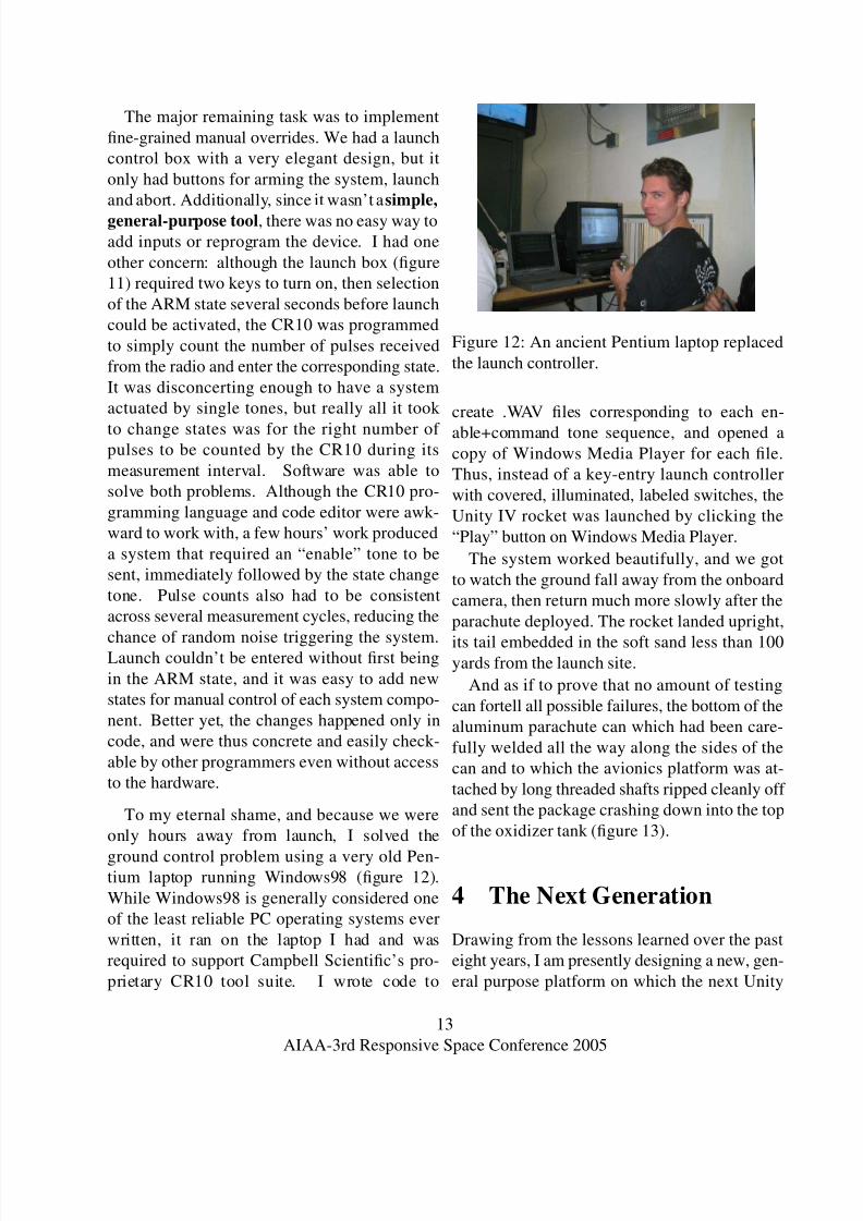
Figure 12: An ancient Pentium laptop replaced
the launch controller.
create .WAV files corresponding to each en-
able+command tone sequence, and opened acopy of Windows Media Player for each file.
Thus, instead of a key-entry launch controller
with covered, illuminated, labeled switches, the
Unity IV rocket was launched by clicking the
“Play” button on Windows Media Player.
The system worked beautifully, and we got
to watch the ground fall away from the onboard
camera, then return much more slowly after the
parachute deployed. The rocket landed upright,
its tail embedded in the soft sand less than 100yards from the launch site.
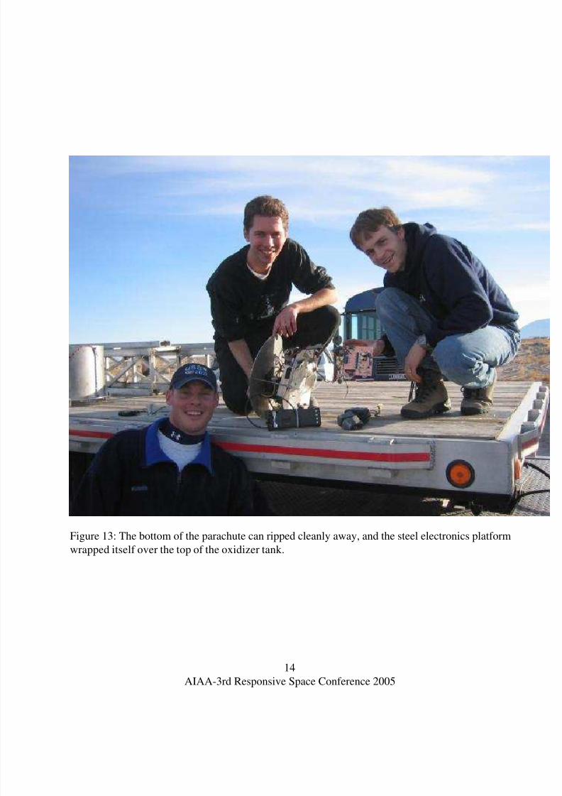
And as if to prove that no amount of testing
can fortell all possible failures, the bottom of the
aluminum parachute can which had been care-
fully welded all the way along the sides of the
can and to which the avionics platform was at-
tached by long threaded shafts ripped cleanly off
and sent the package crashing down into the top
of the oxidizer tank (figure 13).
4 The Next Generation
Drawing from the lessons learned over the past
eight years, I am presently designing a new, gen-
eral purpose platform on which the next Unity
13
AIAA-3rd Responsive Space Conference 2005
8/6/2019 How Not to Design an Avionics System
http://slidepdf.com/reader/full/how-not-to-design-an-avionics-system 15/20
Figure 13: The bottom of the parachute can ripped cleanly away, and the steel electronics platform
wrapped itself over the top of the oxidizer tank.
14
AIAA-3rd Responsive Space Conference 2005
8/6/2019 How Not to Design an Avionics System
http://slidepdf.com/reader/full/how-not-to-design-an-avionics-system 16/20
IV avionics package could be built. I haven’t
worked directly on the project since the 2003
launch, but I recently spoke with Preston Man-
waring, the present avionics team lead, and
found that, encouragingly, he has independently
designed a new system remarkably similar to my
own, but not quite as general-purpose.
My next-generation platform is called Uni-
versalIO. Originally intended as an easy way
for programmers to connect electronic gadgets
like lights and dials to PCs, I quickly realized
that with a little more work, my platform could
also serve the needs of the Unity IV project as
well as several other projects acquaintences of
mine wanted to embark upon. Many of these ac-
quaintences have plenty of computer experienceand good sense for mechanical design, but have
been limited by the difficulty of electronic de-
sign, procurement and implementation. Conse-
quently, UniversalIO boards are intended to be:
1. Versatile, with 4 or more analog inputs and
4 or more outputs capable of switching sig-
nificant amounts of current.
2. Easy to use from both the hardware and
software side by users with minimal elec-
tronics experience.
3. Inexpensive (around $100).
4. Hackable, so that boards can easily be
modified. All designs, interfaces and docu-
mentation will be Free and Open.
5. Fool-resistant, so that common mistakes
don’t cause large amounts of damage.
Several goals are specifically excluded from
my design requirements. First, the board will
not compete with commercial data acquisition
systems, since it will include no special circuitry
for calibration or highly precise measurement.
Other performance features like high sampling
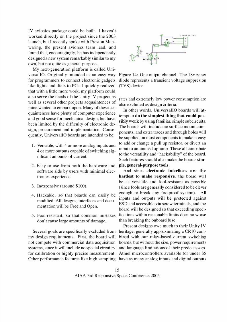
Figure 14: One output channel. The 18v zener
diode represents a transient voltage suppresion
(TVS) device.
rates and extremely low power consumption are
also excluded as design criteria.
In other words, UniversalIO boards will at-
tempt to do the simplest thing that could pos-
sibly work by using familiar, simple subcircuits.
The boards will include no surface mount com-
ponents, and extra traces and through holes will
be supplied on most components to make it easy
to add or change a pull up resistor, or divert an
input to an unused op-amp. These all contribute
to the versatility and “hackability” of the board.
Such features should also make the boards sim-
ple, general-purpose tools.
And since electronic interfaces are the
hardest to make responsive, the board will
be as versatile and fool-resistant as possible
(since fools are generally considered to be clever
enough to break any foolproof system). All
inputs and outputs will be protected against
ESD and accessible via screw terminals, and the
board will be designed so that exceeding speci-
fications within reasonable limits does no worse
than breaking the onboard fuse.
Present designs owe much to their Unity IVheritage, generally approximating a CR10 com-
bined with our relay-based current switching
boards, but without the size, power requirements
and language limitations of their predecessors.
Atmel microcontrollers available for under $5
have as many analog inputs and digital outputs
15
AIAA-3rd Responsive Space Conference 2005
8/6/2019 How Not to Design an Avionics System
http://slidepdf.com/reader/full/how-not-to-design-an-avionics-system 17/20
as a CR10, plus nonvolatile memory and general
programmability. MOSFETs, properly driven,
can source or sink signals referenced to system
supplies at currents greater than 10 amps, but
several of the MOSFET outputs will also option-
ally drive relays, which repeatedly proved indis-
pensible during our Unity IV work. Figure 14
shows a sample schematic for one output chan-
nel.
UniversalIO boards will come standard with
RS232 or USB ports, using a simple command-
line interface similar to those used by network
routers and terminal servers, complete with
built-in help text. This interface will allow users
to immediately begin using the board, without
writing any code. Users can simply attach a de-vice such as a potentiometer (like the volume
knob on a stereo) to the screw terminals corre-
sponding to, say, input 3, then issue the com-
mand “a 3” to read and report the analog value
at input 3. This is an attempt to remember psy-
chology and be the simplest thing that could
possibly work – an engineer tasked with de-
signing an avionics system like ours may be able
to build a simple mock-up in a few hours with-
out writing any code or designing any customcircuits if she has a UniversalIO board handy.
And if UniversalIO boards are inexpensive, ver-
satile, fool-resistant, general-purpose tools, then
this mock-up leaves a clear path toward imple-
menting the actual system using an unmodified
or modified UniversalIO board design. Its Free
and Open design will further reduce barriers to
adoption, avoiding the need to obtain special li-
censes for mass production.
5 Design Principles for Re-
sponsive Systems
Here, then, is the exposition of the lessons
learned over eight years working with the Unity
IV project.
5.1 Do the Simplest Thing That
Could Possibly Work
This principle has become a mantra of extreme
programming (XP), a modern, popular trend in
software development. This quote from an ex-
treme programming site 1 describes the princi-
ple:
So when I asked [KentBeck] (sic),
”What’s the simplest thing that could
possibly work,” I wasn’t even sure. I
wasn’t asking, ”What do you know
would work?” I was asking, ”What’spossible? What is the simplest thing
we could say in code, so that we’ll
be talking about something that’s on
the screen, instead of something that’s
ill-formed in our mind.” I was say-
ing, ”Once we get something on the
screen, we can look at it. If it needs to
be more we can make it more. 2
Responsiveness implies that we don’t have 20
years to think about a problem before solvingit, and doing the simplest thing that could pos-
sibly work reminds the designer to focus on the
problem at hand until she has something con-
crete to work with. Related principles from
extreme programming also apply, such as their
curious reversal of the traditional development
process. Rather than designing a new system
from top to bottom before implementation, XP
advocates often suggest testing first. That is,
creating a simple testable criterion which, whenpassed, indicates that some simple, core part of
the system is functional. Then find a simple so-
lution which passes the test, and finally execute
1http://c2.com/cgi/wiki?ExtremeProgramming2http://c2.com/cgi/wiki?DoTheSimplestThing-
ThatCouldPossiblyWork
16
AIAA-3rd Responsive Space Conference 2005
8/6/2019 How Not to Design an Avionics System
http://slidepdf.com/reader/full/how-not-to-design-an-avionics-system 18/20
the “design” step by integrating that component
with the others. Then the process repeats.
Applying these principles to multimillion dol-
lar satellites which have to work the first time
may seem foolhardy, and in fact I have no per-
sonal experience working with such systems.
However, in the Unity IV project, where we
needed to rapidly develop an inexpensive launch
platform with very limited experience and man-
power, this kind of pragmatic focus was the only
way to produce a working project.
5.2 Remember Psychology
Engineers are used to seeing problems in terms
of abstractions and physics, and consequently
forget the degree to which emotional and psy-
chological considerations can affect a project.
Our default-on recovery system (section 3.3)
was in some ways technically superior to the
default-off alternative, but its backward nature
caused one human error and prevented us from
anticipating a failure mode which actually oc-
curred.
Also, lack of communication with other
teams led to several changes in system require-ments, adding complexity and workload to the
project. A lack of camaraderie, support and per-
sonal leadership in the avionics team made it
hard to stay motivated and involved, and made
it harder to develop trusting relationships with
other team members. Without social cohesion,
team members were less likely to clearly docu-
ment and propagate details of their findings and
solutions, and other members were less likely to
invest time studying those results.Responsiveness can improve morale signifi-
cantly, since results are immediate and directly
connected to applied effort, but also runs the risk
of burning out team members. We saw both ef-
fects, as the promises and demands of an up-
coming launch caused exponential increases in
the amount of time team members were will-
ing to devote to the project, then an equally
quick drop-off afterward as burned-out person-
nel swore off the project entirely.
5.3 Simple, General-Purpose Tools
This principle draws from the Unix design phi-
losophy, built on the notion of a large toolbox of
single-purpose tools which are simple yet versa-
tile. Simple commands for outputting files, sort-
ing, searching or counting lines in a text file have
been used in a bewildering array of applications
for well over 20 years. Programmers find prob-
lems which appear frequently, and over time are
able to develop extremely reliable, predictable
tools for solving those problems.
The CR10 datalogger seems to implement
one of those tools. Though it was never intended
for use as the central controller for a sounding
rocket, it offered a tractable, documented soft-
ware interface for reading sensors, making sim-
ple decisions and signalling outputs. Because
we found that most of the time, those outputs
needed to switch significant amounts of current,
UniversalIO integrates that tool with general-purpose switching devices like relays.
The Free Software and Open Source commu-
nities seem to do a good job of thinking in terms
of simple, general purpose tools. Rather than
focusing only on creating a product whose in-
ternals will be hidden from its users, Free soft-
ware developers tend to look for others who
have solved subproblems of their task already,
and look for ways their subsolutions might make
other problems easier to solve. A Free softwaredeveloper might try out a dozen different Free
software libraries during the course of a day
while searching for the simplest possible solu-
tion to a problem, whereas a proprietary devel-
oper would have to consider licensing and cost
considerations for each candidate library. Small,
17
AIAA-3rd Responsive Space Conference 2005
8/6/2019 How Not to Design an Avionics System
http://slidepdf.com/reader/full/how-not-to-design-an-avionics-system 19/20
useful but perhaps unmarketable tools get built
and distributed, and developers are motivated to
keep their solutions easily hackable by the next
programmer who comes along. All these things
can improve agility and response time.
5.4 Prototype Systems Need to be
Responsive to Human Interven-
tion
Although the Utah Test and Training Range re-quired us to identify and plan for a wide range
of failure contingencies, each failure we experi-
enced fell outside the realm of possibilities we
had considered. While some of those failures
were unavoidable once initiated, several would
not have been if our avionics system were more
flexible.
Leaving an engineer to design a system which
can handle any situation invites the kind of unfo-
cused meandering which kept me from produc-ing relevant systems during my first few years
in the project. Instead, what we needed was lots
of experience solving actual, necessary prob-
lems which could have come from the extreme-
programming-style test, implement, design cy-
cle described earlier. And rather than adding
complexity to avoid contingencies which in ret-
rospect seem quite unlikely, we should have fo-
cused on making the existing individual system
elements easy to access by the human operators.
Adding manual overrides for each control
system turned out to be a relatively small
amount of work, especially when using a laptop,
a general-purpose tool, for the ground station. If
it had been implemented earlier, it could have
prevented a large amount of wasted effort.
5.5 Electronic interfaces are the
hardest to make responsive
Hardware has been defined as “the parts of a
[system] which can be kicked” (attributed to
Henri Karrenbeld). Mechanical systems havelimited complexity compared to more abstract
systems like electronics and softare, and tend to
appeal to physical intuition. Software quickly
becomes extremely complex, but comes with
handy features like discretization into 1’s and
0’s and the ability to be copied, backed up and
examined in arbitrary detail using debuggers.
Electronics comes with the complexity of soft-
ware, the limitations of physics, and is increas-
ingly manufactured in microscopic form.It’s generally much easier to change a dozen
output signals than to rewire a dozen pins, and
much easier to verify when that task has been
performed correctly. Poor software decisions
can be undone in a text editor, but one poor sol-
der joint can destroy hundreds of dollars worth
of components.
It was our experience that a good machinist
can modify a mechanical device quite rapidly,
often even in the field, and a good program-mer can change hundreds of lines of code in
a few hours to respond to changing require-
ments. Consequently, electronic systems have
the greatest need for general-purpose, versatile
tools which can be rapidly adapted and deployed
for responsive solutions.
6 Conclusion
The Unity IV project is, to our knowledge, thelargest university-built sounding rocket in the
world. Our experiences over the eight year pe-
riod from 1995 to 2003 provided an excellent
hands-on education in implementing real elec-
tronic systems. Through the design, testing
and reimplementation of our system, we have
18
AIAA-3rd Responsive Space Conference 2005
8/6/2019 How Not to Design an Avionics System
http://slidepdf.com/reader/full/how-not-to-design-an-avionics-system 20/20
observed several overarching principles which
contribute to responsive, effective deployment
of aerospace systems.
First, the slogan “do the simplest thing that
could possibly work,” when combined with
other principles from extreme programming,
promotes focused, steady, measurable progress
in achieving project goals.
Second, taking human elements into consid-
eration promotes happy, supportive teams who
work well together. Community-mindedness
promotes the third principle, thinking in terms
of simple, general-purpose tools which are ver-
satile, easily tested and transplanted into other
systems.
Fourth, we found that rapidly developed sys-tems should allow humans maximal control over
their capabilities in order to maximize respon-
siveness. And finally, we found that electrical
systems should be given priority over software
and mechanical systems in terms of developing
responsive, versatile, dependable solutions.
19
AIAA-3rd Responsive Space Conference 2005
Recommended


![REQUEST FOR PROPOSAL [RFP] FOR RETROFIT/ UPGRADE OF AVIONICS … · 2015. 2. 13. · Partial solutions i.e., upgrade of only part of avionics suite will also not be acceptable. 4.3](https://img.pdfslide.net/doc/110x75/60ff12ecf4f2ba079e74382b/request-for-proposal-rfp-for-retrofit-upgrade-of-avionics-2015-2-13-partial.jpg)