ISSN 1068-798X, Russian Engineering Research, 2009, Vol. 29, No. 2, pp. 187–190. © Allerton Press, Inc., 2009.Original Russian Text © E.V. Bakhtamov, A.M. Voronin, S.V. Gorin, 2009, published in Vestnik Mashinostroeniya, 2009, No. 2, pp. 86–87.
187
The development program for nuclear power inRussia calls not only for stationary power plants butalso for low-power floating nuclear power plants, usingicebreaker power units that have proven reliable andsafe over years of operation. Nevertheless, the design ofsuch floating power plants includes a number of defi-ciencies that affect plant safety, for whose eliminationcertain recommendations have been made [1]. Stillunaddressed is the question of vibration and noiseaccompanying the operation of such nuclear plants.
The first low-power floating nuclear power plant—the 20870 unit with a KLT-40S reactor—was installedat Sevmash production facility, in Severodvinsk. Sub-sequent units are planned for remote locations in north-ern Siberia. If they prove successful, they will beexported to Pacific nations and to other regions, such asthe Middle East, where freshwater problems may besolved by means of desalination units based on suchlow-power nuclear plants.
To ensure the required thermophysical parametersin power-plant operation, the circulating-water flowrates necessary at the given temperature must be estab-lished. Usually, this is done during the debuggingphase, by installing choke plates in the pipelines so asto create additional hydraulic drag and reduce the cool-ant-water flow.
Given the proposed power-plant location, the differ-ence in water temperature will be 30
°
C or more. Hence,in the proposed design, where the same pumps are pro-vided for all the pumping stations, choke plates with awide hydraulic-drag range are needed. When waterflows at high speed around the choke plates, hydrody-namic noise and vibration will be generated.
The noise and vibration not only impair staff pro-ductivity but also have an adverse environmentalimpact. This is a particular concern for hydrodynamicnoise in the water surrounding the floating plant, whichmay drive fish and birds from their traditional habitat.
Qualitative evaluation of the contribution of thechoke plates to the hydrodynamic noise level may bebased on vibroacoustic tests on a hydrodynamic standsimulating the actual hydraulic system (Fig. 1) [2]. Thevibrations are produced by a TsN-104 circulatory pump
1
,whose speed (and correspondingly the speed of thewater flow) may be regulated smoothly from 500 to3000 min
–1
. The teststand also includes a 5-m
3
chamber
2
with an air-ventilation valve
3
, a supply tank
4
, pipeline
5
(
D
st
= 150 mm), and irreversible valves
6
. The supplysystem consists of pipe
7
, manual pump
8
, and pistonpump
9
. The working medium is distilled water. Thechoke plates are installed in the flanged joint
10
.Vibroacoustic tests are conducted using Bruel and
Kjaer (Denmark) instruments. The level of vibration andpressure pulsation is measured using 4639 accelerome-ters and 8103 miniature hydrophones, installed outsidethe water flux in special housings welded into the pipewall. The apparatus for recording and analysis of thelevels of vibration and pressure pulsations includes2635 preamps, 2031 broadband analyzers, and2308 automatic recorders.
To eliminate the influence of uncontrollable gas bub-bles and air-filled cavities on the vibroacoustic-test data,water is pumped into the teststand after each choke-plateinstallation so as to drive out the air through ventilationvalve
3
. Then, an excess pressure of 0.2 MPa is createdin the system and maintained for days, so as to permit thedissolution of air inclusions in hard-to-reach locations.
During debugging, the coolant-water flow rate in thefourth loop is refined so as to ensure the required thermo-physical characteristics of the power plant. This entailsselecting the choke-plate diameter such that the waterflow rate in the loop is optimal after insertion of thechoke plate. The range of diameters required may bebroad, depending on the temperature of the circulatingwater. There tests are conducted on a teststand simulat-ing the fourth loop, both with classical choke disks
Hydrodynamic Noise in Water-Supply Systems for Nuclear Power Plants
E. V. Bakhtamov, A. M. Voronin, and S. V. Gorin
Sevmashvtuz Technical University, Severodvinsk
Abstract
—The results of vibro–acoustic investigation of laboratory model of the fourth circuit of nuclearpower plant are presented. It is shown that the spectrogram of hydrodynamic noises is the solid spectrum, onthe background of which there are the pronounced discrete components. The centrifugal pump and the throttlingorifice are the main reasons of vibrations and noise. The recommendations of how to minimize the hydrody-namic noise in such systems are given. The results of investigation can be used for stationary and floatingnuclear power plants and also for other types of power plants.
DOI:
10.3103/S1068798X09020166
188
RUSSIAN ENGINEERING RESEARCH
Vol. 29
No. 2
2009
BAKHTAMOV et al.
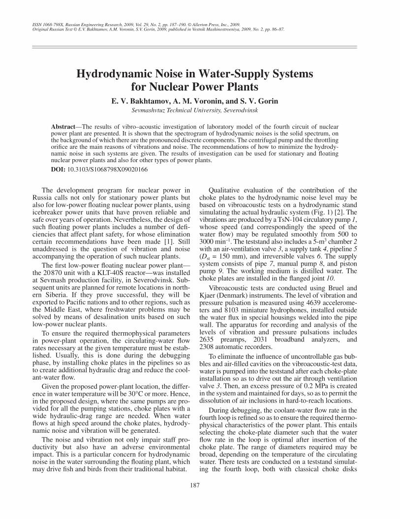
(with a central hole characterized by a diameter of 42,68, 78, 84, and 90 mm) and with a choke plate over which40 15-mm holes are uniformly distributed (Fig. 2).
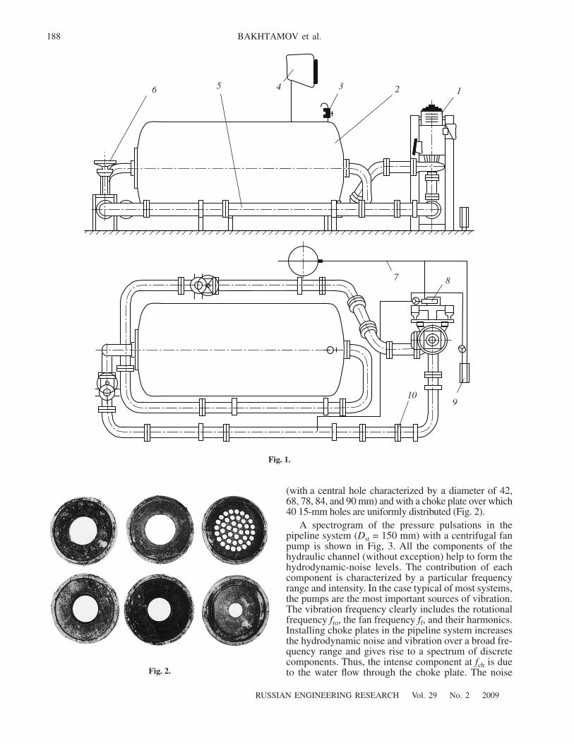
A spectrogram of the pressure pulsations in thepipeline system (
D
st
= 150 mm) with a centrifugal fanpump is shown in Fig, 3. All the components of thehydraulic channel (without exception) help to form thehydrodynamic-noise levels. The contribution of eachcomponent is characterized by a particular frequencyrange and intensity. In the case typical of most systems,the pumps are the most important sources of vibration.The vibration frequency clearly includes the rotationalfrequency
f
ro
, the fan frequency
f
f
, and their harmonics.Installing choke plates in the pipeline system increasesthe hydrodynamic noise and vibration over a broad fre-quency range and gives rise to a spectrum of discretecomponents. Thus, the intense component at
f
ch
is dueto the water flow through the choke plate. The noise
Fig. 2.
123456
7 8
910
Fig. 1.
RUSSIAN ENGINEERING RESEARCH
Vol. 29
No. 2
2009
HYDRODYNAMIC NOISE IN WATER-SUPPLY SYSTEMS 189
160
150
140
130
120
110
100
90200 400 600 800 1000 1200 1400 1600
f
, Hz
L
, dB
0
f
f
f
ch
f
ro
Fig. 3.
150
140
130
120
110
100
90
80900 950 1000 1050 1100 1150 1200 1250
f
, Hz
∆
p
= 70 kPa
1155 Hz985 Hz
∆
p
= 20 kPa
30
L
, dB
Fig. 4.
190
RUSSIAN ENGINEERING RESEARCH
Vol. 29
No. 2
2009
BAKHTAMOV et al.
levels at the rotation frequency
f
ro
and fan frequency
f
f
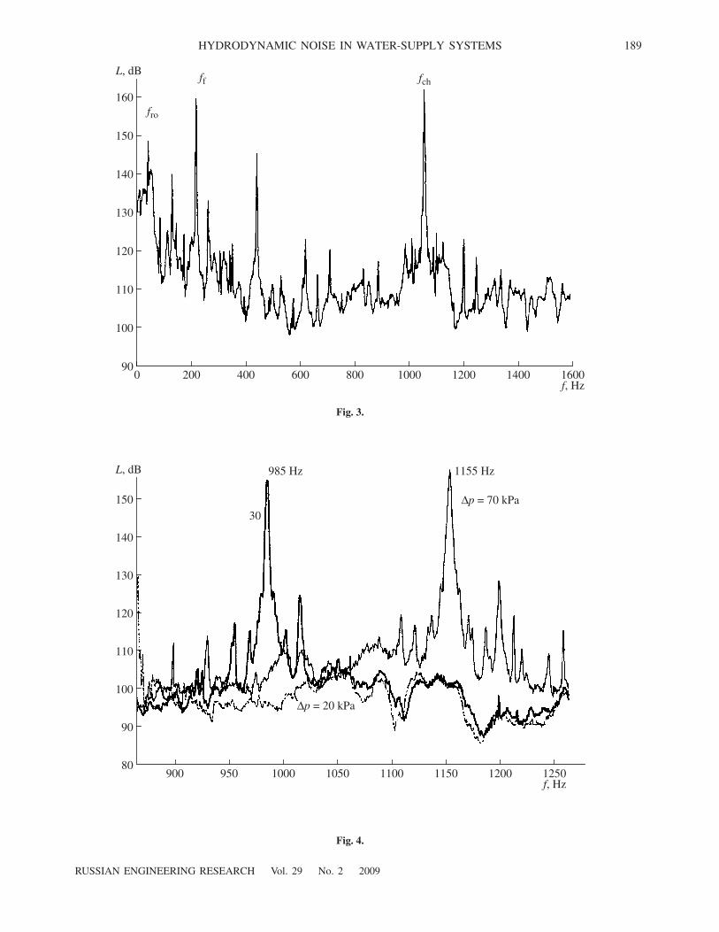
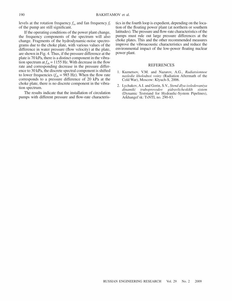
of the pump are still significant.If the operating conditions of the power plant change,
the frequency components of the spectrum will alsochange. Fragments of the hydrodynamic-noise spectro-grams due to the choke plate, with various values of thedifference in water pressure (flow velocity) at the plate,are shown in Fig. 4. Thus, if the pressure difference at theplate is 70 kPa, there is a distinct component in the vibra-tion spectrum at
f
ch
= 1155 Hz. With decrease in the flowrate and corresponding decrease in the pressure differ-ence to 30 kPa, the discrete spectral component is shiftedto lower frequencies (
f
ch
= 985 Hz). When the flow ratecorresponds to a pressure difference of 20 kPa at thechoke plate, there is no discrete component in the vibra-tion spectrum.
The results indicate that the installation of circulationpumps with different pressure and flow-rate characteris-
tics in the fourth loop is expedient, depending on the loca-tion of the floating power plant (at northern or southernlatitudes). The pressure and flow-rate characteristics of thepumps must rule out large pressure differences at thechoke plates. This and the other recommended measuresimprove the vibroacoustic characteristics and reduce theenvironmental impact of the low-power floating nuclearpower plant.
REFERENCES
1. Kuznetsov, V.M. and Nazarov, A.G.,
Radiatsionnoenasledie kholodnoi voiny
(Radiation Aftermath of theCold War), Moscow: Klyuch-S, 2006.
2. Lychakov, A.I. and Gorin, S.V.,
Stend dlya issledovaniyadinamiki truboprovodov gidravlicheskikh sistem
(Dynamic Teststand for Hydraulic-System Pipelines),Arkhangel’sk: TsNTI, no. 290-83.
Recommended


![SECTION 9 VALVES, SERVOS, MOTORS, AND ROBOTSftp.feq.ufu.br/Luis_Claudio/Segurança/Safety... · Hydrodynamic Noise: IEC 534-8-4 [1] 9.78 Aerodynamic Noise: IEC 534-8-3 [2] 9.78 NOISE](https://img.pdfslide.net/doc/110x75/5e8f7b07999d11497b55121f/section-9-valves-servos-motors-and-asafety-hydrodynamic-noise-iec-534-8-4.jpg)