2
38th Annual Conference of the IEEE Industrial Electronics Society (IECON 2012), Montréal, QC, CA.
Co-Simulation of PEV Coordination Schemes over a FiWi Smart Grid Communications Infrastructure
Presented by: Martin Lévesque INRS (Québec, Canada)PhD student

3
Outline
• Introduction
• Impact study of uncoordinated PEV charging
• Proactive and reactive coordination schemes
• Communications and power distribution network co-simulation
• Co-simulation results
• Conclusions

4
Introduction to Smart Grid● Current electrical grid:
● One-way flow of energy.
● Exchange of information from generators to substations.
● Cannot handle large-scale deployment of distributed renewable energy ressources and/or electric vehicles.
● Smart Grid :
● Two-way flow of energy and information.
● Monitoring and control of the grid using communications and sensor technologies.
Current electrical grid
Smart Grid
Sources: http://www.smartgrid.epri.com/Demo.aspxhttp://www.incontext.indiana.edu/2010/july-aug/article3.asp

5
Is uncoordinated PEV charging a problem ?● In some works [1], it was found that PEV charging can significantly stress the distribution network on a local scale.
● While in some other distribution systems [2], little negative impact was observed.
● Thus, we first look into uncoordinated PEV charging to verify their findings.
[1]
[2]

6
Configurations - Topology● Widely used IEEE 13-Node distribution test feeder.● Substation steps down the 115kV transmission network to 4.16kV.● Each node in the feeder aggregates one or more low voltage residential network(s).● Total number of 18 residential networks, totalling 342 customer households.
Fig. : Single line diagram of the modified IEEE 13-Node network.
7
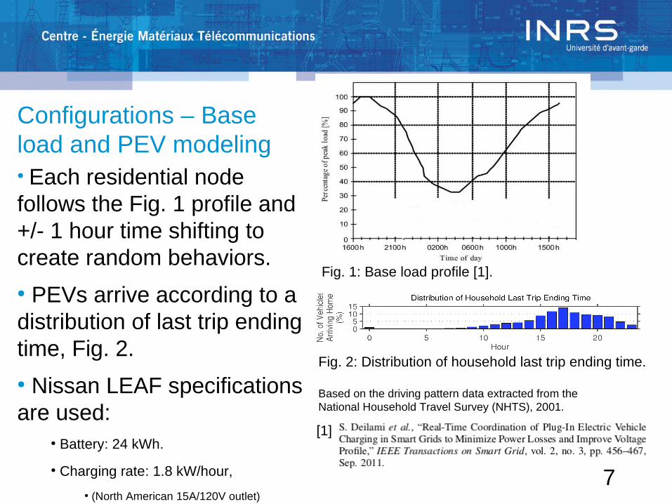
Configurations – Base load and PEV modeling● Each residential node follows the Fig. 1 profile and +/- 1 hour time shifting to create random behaviors.● PEVs arrive according to a distribution of last trip ending time, Fig. 2. ● Nissan LEAF specifications are used:
● Battery: 24 kWh.
● Charging rate: 1.8 kW/hour,
● (North American 15A/120V outlet)
Fig. 2: Distribution of household last trip ending time.
Based on the driving pattern data extracted from the National Household Travel Survey (NHTS), 2001.
Fig. 1: Base load profile [1].
[1]
8
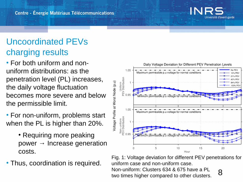
Uncoordinated PEVs charging results● For both uniform and non-uniform distributions: as the penetration level (PL) increases, the daily voltage fluctuation becomes more severe and below the permissible limit.
● For non-uniform, problems start when the PL is higher than 20%.
● Requiring more peaking power → Increase generation costs.
● Thus, coordination is required.Fig. 1: Voltage deviation for different PEV penetrations for uniform case and non-uniform case.Non-uniform: Clusters 634 & 675 have a PL two times higher compared to other clusters.

9
Coordinated PEVs● Coordination solutions can be grouped into two categories:
● Proactive scheduling: PEVs are scheduled to avoid critical voltage fluctuations.
● Reactive control: Fix the problem when it occurs.
Fig.: Coordinated and uncoordinated PEV controlsolutions.

10
Proactive algorithms● First fit: Start time of PEV charging is the first available slot that does not violate (1,2).● Smart load management (SLM) [1]: Find the slot minimizing (3,4) without violating (1,2).
(1) Voltage contraint.
(2) Maximum power demand.
Constraints:
Parameters:
(3)
(4)
[1]
11
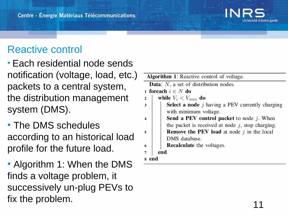
Reactive control● Each residential node sends notification (voltage, load, etc.) packets to a central system, the distribution management system (DMS). ● The DMS schedules according to an historical load profile for the future load.● Algorithm 1: When the DMS finds a voltage problem, it successively un-plug PEVs to fix the problem.
12
Reactive control – Sensor type● The reactive control mechanism is influenced by the sensor type being used.● Two sensor types:
● Data rate based: Measurements are sent periodically. As the rate increases, the probability that an information is outdated decreases.
● Event based: Send a measurement only when the difference between 2 measurements is higher than a certain threshold.
13
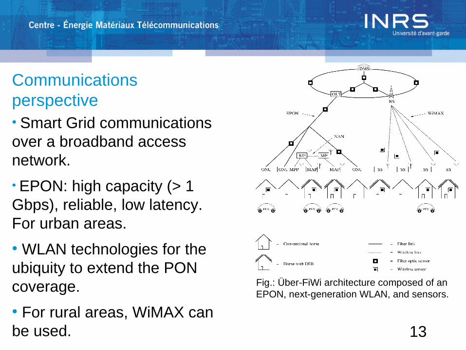
Communications perspective● Smart Grid communications over a broadband access network. ● EPON: high capacity (> 1 Gbps), reliable, low latency. For urban areas.● WLAN technologies for the ubiquity to extend the PON coverage. ● For rural areas, WiMAX can be used.
Fig.: Über-FiWi architecture composed of an EPON, next-generation WLAN, and sensors.

14
On Co-simulation● OMNeT++ is used for the FiWi simulator. ● A power system layer is also created by calling OpenDSS for voltage, power, losses, etc., according to the load at each node in the network.● Each residential node is mapped to either an ONU or WLAN node.● Thus, both perspectives work as an integrated system.
Fig.: Power distribution network and FiWi co-simulator.

15
Proactive co-simulation results● As expected, with random charging, problems are observed during peak hours.
● SLM fully distributes the load and fills the valley, whereby first fit can increase the peak duration.
● Only 1-2 Mbps of throughput was required with an end-to-end delay of 1-8 ms.
Fig.: Proactive co-simulation results. The penetration level is set to 66%, uniform distribution.

16
Reactive co-simulation results● As the DMS profile could not match the real load, we add some sudden high loads to create a stress scenario.● As expected, critical voltage fluctuations are observed during these sudden high loads.
Fig.: Reactive co-simulation results.

17
Reactive co-simulation results● The reactive control algorithm is tested with data rate based sensors.
● Thus, as the data rate of sensors increases, the critical voltage duration decreases.
● In this example, to have a critical voltage duration lower than 1 second, one need to set the data rate to at least 4 packets per second.
Fig.: Critical voltage duration as a function of the data rate of sensors.

18
Conclusions
• Uncoordinated charging of PEVs can cause critical voltage fluctuations and overload utility assets as the penetration level increases.
• To overcome these issues, we used a converged broadband access network to coordinate PEVs using a proactive algorithm at the DMS.
• However, the information available at the DMS can mismatch the actual voltage and load in the network.
• We proposed a reactive control algorithm to fix and un-plug PEVs to quickly solve critical voltage fluctuations.

19
Future work
• Coordinate not only PEVs, but also renewable energy sources.
• The considered broadband access network was not loaded. The communications must take into account triple-play traffic (video, voice, data).

20
Questions ?
Recommended