IEEE’sHands on Practical Electronics (HOPE)
Lesson 1: Introduction
Course Information
• This is the IEEE Hands on Practical Electronics (HOPE) decal
• EE98/198
• Day/Time: Wed 5-6:30P
• Website: http://ieee.eecs.berkeley.edu/– Lectures and labs will be posted each week
This Week
• The goal of today’s lesson is to:– Become familiar with some basic EE components
and tools
– Build a basic circuit
• We will explain the underlying principles of the circuit in the next lesson
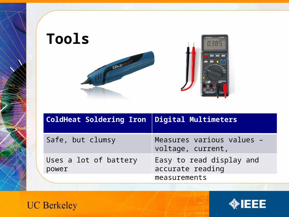
Tools
ColdHeat Soldering Iron Digital Multimeters
Safe, but clumsy Measures various values – voltage, current, resistance, etc.
Uses a lot of battery power Easy to read display and accurate reading measurements
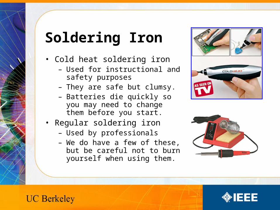
Soldering Iron
• Cold heat soldering iron– Used for instructional and safety
purposes– They are safe but clumsy.– Batteries die quickly so you may
need to change them before you start.
• Regular soldering iron– Used by professionals– We do have a few of these, but be
careful not to burn yourself when using them.
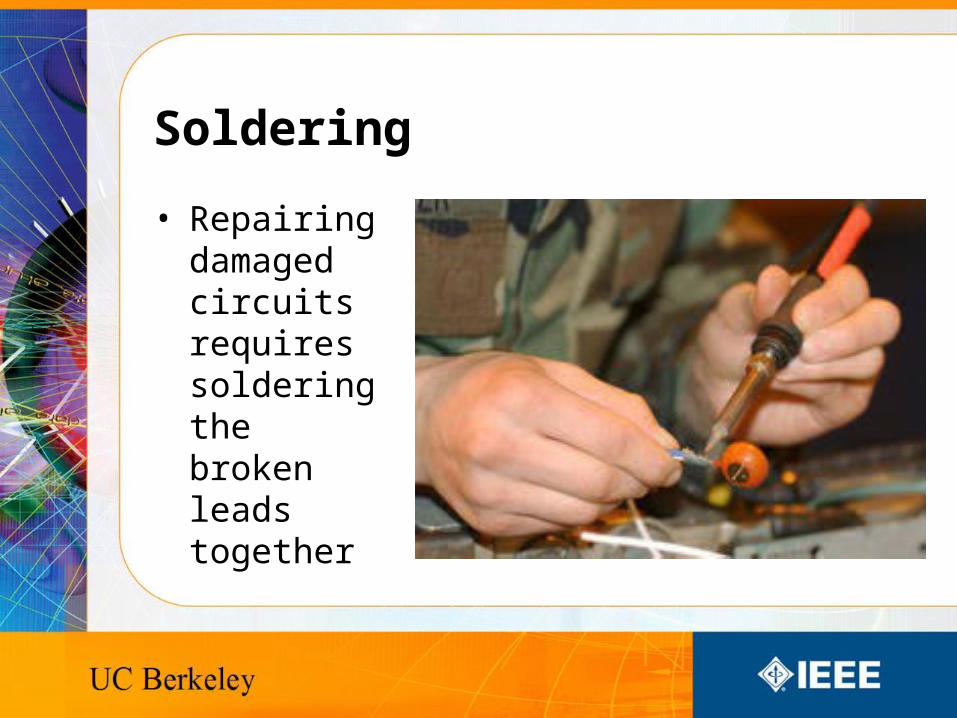
Soldering
• Repairing damaged circuits requires soldering the broken leads together
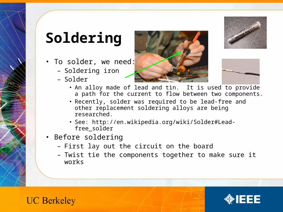
Soldering
• To solder, we need:– Soldering iron– Solder
• An alloy made of lead and tin. It is used to provide a path for the current to flow between two components.
• Recently, solder was required to be lead-free and other replacement soldering alloys are being researched.
• See: http://en.wikipedia.org/wiki/Solder#Lead-free_solder
• Before soldering– First lay out the circuit on the board– Twist tie the components together to make sure it works
Soldering
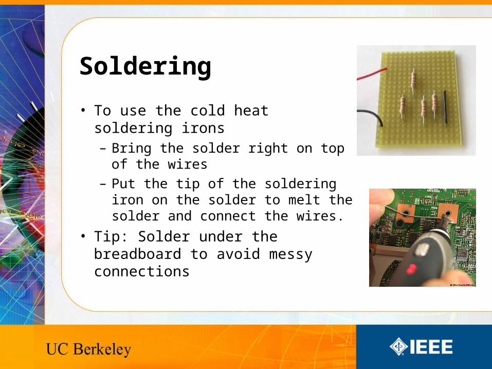
• To use the cold heat soldering irons– Bring the solder right on top of the
wires
– Put the tip of the soldering iron on the solder to melt the solder and connect the wires.
• Tip: Solder under the breadboard to avoid messy connections
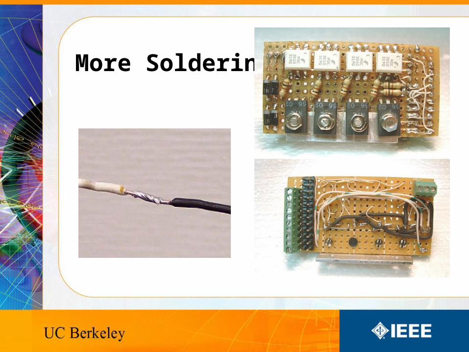
More Soldering
Soldering Usage
• Soldering is used to assemble circuits
• It is an alternative to welding. Plumbing pipes can also be soldered together
• Solder provides a nearly permanent, but reversible connection
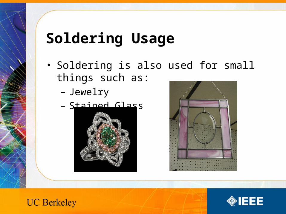
Soldering Usage
• Soldering is also used for small things such as:– Jewelry
– Stained Glass
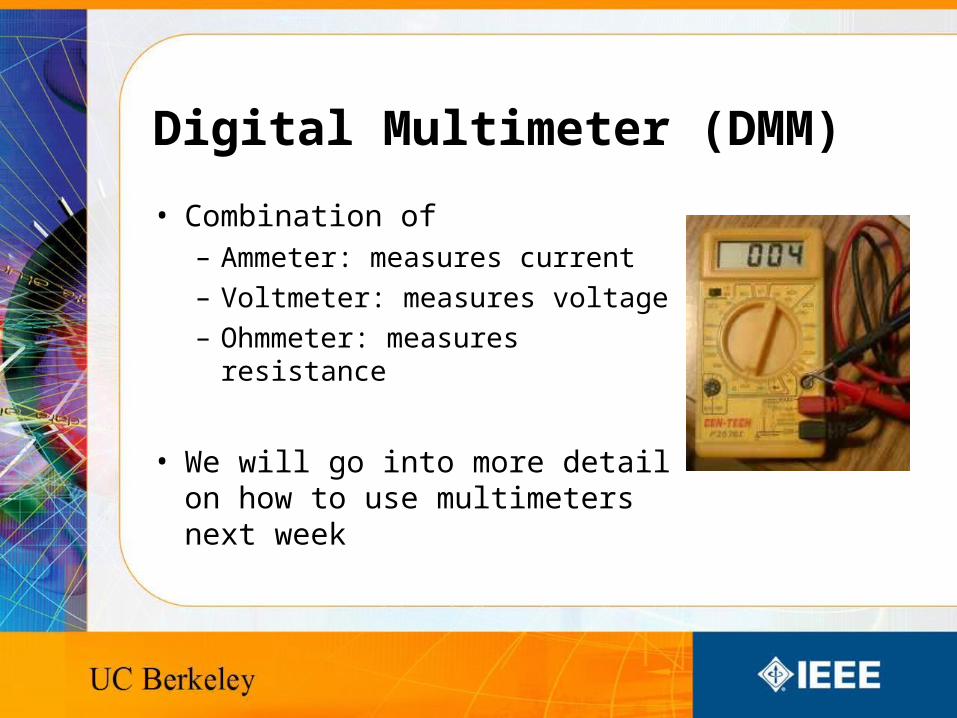
Digital Multimeter (DMM)
• Combination of– Ammeter: measures current
– Voltmeter: measures voltage
– Ohmmeter: measures resistance
• We will go into more detail on how to use multimeters next week
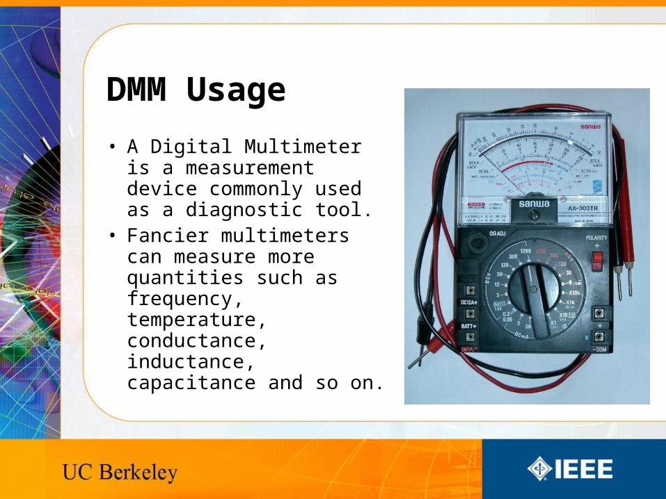
DMM Usage
• A Digital Multimeter is a measurement device commonly used as a diagnostic tool.
• Fancier multimeters can measure more quantities such as frequency, temperature, conductance, inductance, capacitance and so on.
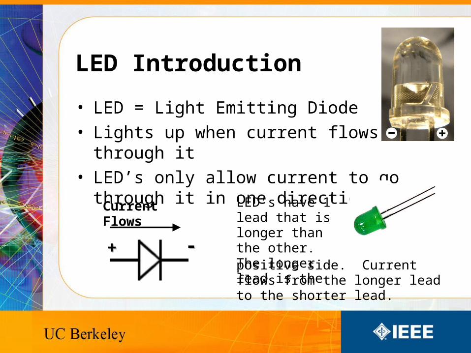
LED Introduction
• LED = Light Emitting Diode
• Lights up when current flows through it
• LED’s only allow current to go through it in one direction
LED’s have 1 lead that is longer than the other. The longer lead is thepositive side. Current flows from the longer lead to the shorter lead.
Current Flows
++ --
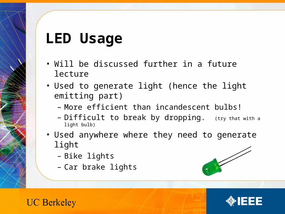
LED Usage
• Will be discussed further in a future lecture
• Used to generate light (hence the light emitting part)– More efficient than incandescent bulbs!– Difficult to break by dropping. (try that with a light bulb)
• Used anywhere where they need to generate light– Bike lights
– Car brake lights

Circuits
• Closed loop – There is a path for the current to flow back to the other end of the battery
• Circuits will only work if there is a closed loop• The following circuit diagram contains a closed loop
starting from the battery to the resistor, through the first LED and then back to the battery
9 Volts
1 or 2 Resistors in Series (a line) LEDs...up to 5 ….
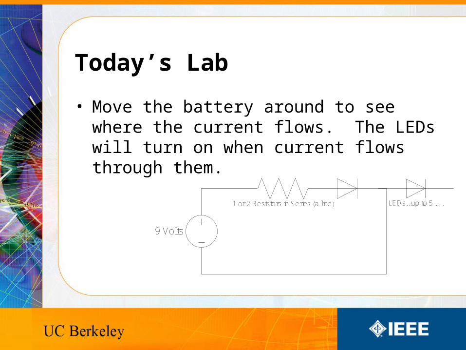
Today’s Lab
• Move the battery around to see where the current flows. The LEDs will turn on when current flows through them.
9 Volts
1 or 2 Resistors in Series (a line) LEDs...up to 5 ….
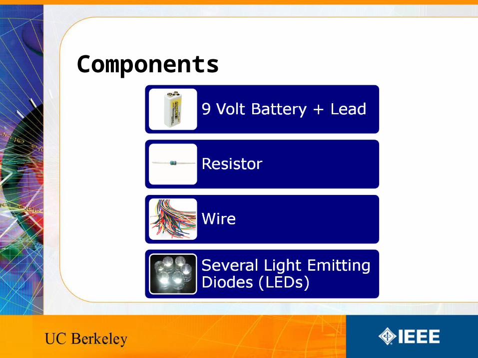
Components
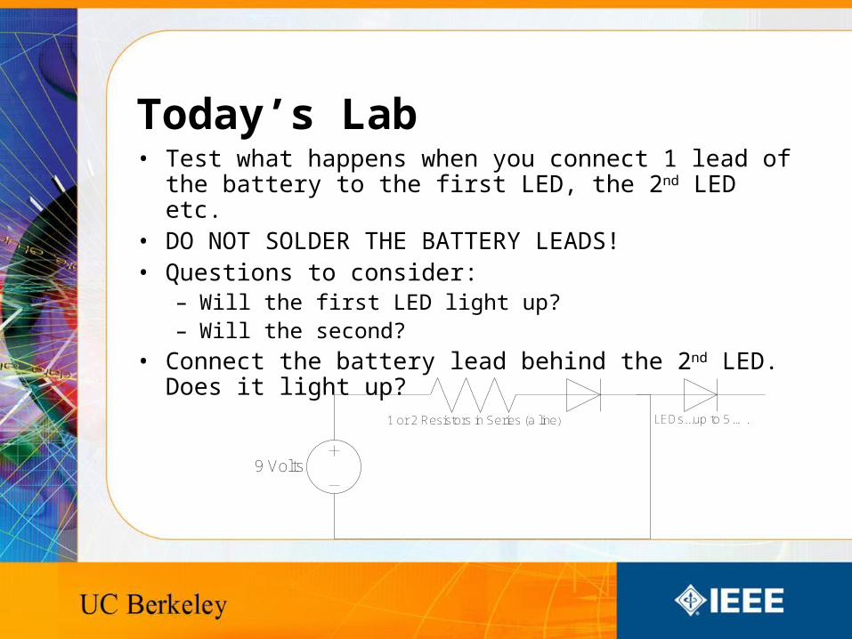
Today’s Lab• Test what happens when you connect 1 lead of the battery to
the first LED, the 2nd LED etc.• DO NOT SOLDER THE BATTERY LEADS!• Questions to consider:
– Will the first LED light up?– Will the second?
• Connect the battery lead behind the 2nd LED. Does it light up?
9 Volts
1 or 2 Resistors in Series (a line) LEDs...up to 5 ….
Recommended