ii
PLANNING AND IMPACT OF DISTRIBUTED GENERATION IN SESB
EXISTING SYSTEM
KASMAWATI BINTI RASMIN
A project report submitted in partial
fulfillment of the requirement for the award of the
Degree of Master of Electrical Engineering
Faculty of Electrical and Electronic Engineering
UniversitiTun Hussein Onn Malaysia
JULY 2014
vi
ABSTRACT
In the recent years the electrical power networks are undergoing rapid restructuring
and developing process worldwide. Advancement in technologies and concern about
the environmental impacts have led to increase interconnection of renewable energy
based distributed generations (DGs) in distribution networks. The DGs have
significant impacts on the distribution systems; these impacts may be either
positively or negatively depending on the modified interconnected DG distribution
network structure. It will be necessary to consider many issues concerning these
impacts. In this project, an investigation of DGs impacts on voltage profile and
power losses in radial distribution networks is introduced and explained. The
method of determining size and placing the DG unit using classical grid algorithm
search has been analyses in this report. The performance of the interconnected DG
distribution network in terms of power losses and voltage profile also has been
analyzed. A comparison between many cases with different numbers, sizes and
locations of interconnected DGs are considered and discussed. Detailed simulations
using PSS ADEPT are conducted in order to explain and verify the results. At the
end of this project, the result showed the significant improvement in terms of power
losses and voltage stability.
vii
ABSTRAK
Pada tahun kebelakangan ini rangkaian kuasa elektrik sedang menjalani penyusunan
semula yang pesat membangun di seluruh dunia. Kemajuan dalam teknologi dan
kebimbangan mengenai kesan alam sekitar telah membawa kepada peningkatan
keperluan tenaga boleh diperbaharui dengan menggunakan Pembahagian Penjanaan
(DG) dalam rangkaian pembahagian. Dimana DG memberi kesan ketara ke atas
sistem pembahagian iaitu impak dari segi positif dan negatif. Namun ianya
bergantung kepada struktur rangkaian pengedaran DG yang telah diubah suai.
Perkara ini diambil kira kerana banyak isu-isu berkaitan impak ini perlu diketahui.
Dalam projek ini, analisis impak DG pada profail voltan dan kehilangan kuasa dalam
taburan rangkaian pembahagian diperkenalkan dan dijelaskan. Kaedah penentuan
saiz dan lokasi penyambungan DG menggunakan algoritma carian grid klasik telah
digunakan dalam laporan ini. Prestasi rangkaian pembahagian DG dari segi
kehilangan kuasa dan profail voltan serta perbezaan senario yang pelbagai dengan
cara menggunakan saiz unit dan lokasi DG yang berbeza dianalisa dan dibincangkan.
Simulasi terperinci menggunakan PSS ADEPT dijalankan untuk menjelaskan dan
mengesahkan keputusan analisa. Pada akhir projek ini keputusan menunjukkan
peningkatan yang ketara dari segi kehilangan kuasa dan kestabilan voltan.
viii
CONTENTS
DECLARATION OF REPORT STATUS i
EXAMINERS’ DECLARATION ii
TITLE iii
STUDENT’S DECLARATION iv
DEDICATION v
ACKNOWLEDGEMENTS vi
ABSTRACT vii
CONTENTS viii
LIST OF TABLES ix
LIST OF FIGURES x
LIST OF SYMBOLS & ABBREVIATIONS xi
LIST OF APPENDICES xii
CHAPTER 1 INTRODUCTION 1
1.1 Traditional Concept of Power Systems 1
1.2 New Concept of Power Systems 3
1.3 Distributed Generation 4
1.4 Problem statements 5
1.5 Project Objectives 7
1.6 Project Scope 7
1.7 Outline of report 8
CHAPTER 2 LITERATURE REVIEW 10
2.1 Introduction 10
2.2 Types of Distributed Generation 11
2.2.1 Photovoltaic Systems 11
2.2.2 Wind Turbines 13
ix
2.2.3 Fuel Cells 14
2.2.4 Micro-Turbines 15
2.2.5 Induction and Synchronous Generator 16
2.3 Impact of Distributed Generation on Power system Grids 17
2.3.1 Impact of DG on Voltage Regulation 18
2.3.2 Impact of Dg on Losses 20
2.3.3 Impact of DG on Harmonics 21
2.3.4 Impact of Dg on Short Circuit Level of the
Network 23
2.4 Protection Coordination 25
2.5 Islanding of a Power Network 28
2.5.1 Intentional Islanding 29
2.5.2 Islanding Detection 30
2.6 Previous Study 32
CHAPTER 3 METHODOLOGY 34
3.1 Introduction 34
3.2 Classical Grid Search Algorithm 34
3.3 PSS ADEPT Software 38
3.4 Description Of Project Phases 38
3.4.1 Literature review on previous works about
Distribution Generation systems 39
3.4.2 Data collecting and modelling the distributed generation 39
3.4.3 Software Development 39
3.4.4 Results and Discussions 39
3.4.5 Conclusion and Recommendations 39
CHAPTER 4 RESULTS AND DISCUSSIONS 40
4.1 Introduction 40
4.2 Results and analysis 41
4.2.1 Impact of system with single DG 42
4.2.2 Impact of system with double DG 45
x
4.2.3 Impact DG in voltage stability 48
4.3 Summarized Result 51
CHAPTER 5 CONCLUSIONS AND RECOMMENDATIONS 53
5.1 Conclusions 53
5.2 Recommendations 54
REFERENCES 55
APPENDICES A-B 59-60
vii
LIST OF TABLES
2.1 Size of DG 11
2.2 Harmonic current injection for DG per IEEE 519-1992 22
4.1 Different scenario cases considered in this project 41
4.2 Line Loss with Single DG (Case b) 42
4.3 Line Loss with double DGs (Case c) 45
4.4 Voltage profile 48
4.5 12 Bus Systems Overall Result 52
x
LIST OF FIGURES
1.1 Traditional industrial conception of the electrical
energy supply 2
1.2 New industrial conception of the electrical energy
supply 3
2.1 Schematic diagram of a photovoltaic system 12
2.2 Schematic operation diagram of a wind turbine 13
2.3 Schematic diagram of a fuel cell 14
2.4 Schematic diagram of a micro-turbine 15
2.5 Voltage profiles with and without DG 18
2.6 Comparison between pure sinusoidal wave and
distorted wave 21
2.7 Fault contributions due to DG units 1, 2 and 3 are
embedded in the system 24
2.8 Commonly transformer connections used with DG 26
2.9 Islanding of a DG system 28
3.1 Flowchart for DG Placement 37
4.1 PPU Batu Sapi distribution network system 40
4.2 12- bus Radial Distribution system 41
xi
4.3 Initial Line PLoss without DG VS PLoss with single DG 43
4.4 Initial Line QLoss (MVAr) without DG VS
QLoss (MVAr) with DG 44
4.5 Line PLoss (MW) with Single DG and Double DG 46
4.6 Line QLoss (MVAr) with Single and Double DG 47
4.7 12- Bus Voltage Profile (p.u) 49
4.8 12- Bus Optimum Size of DG (MW) 50
4.9 12 Bus Line Losses P Loss (MW) 50
4.10 12 Bus Line Losses Q Loss (MVAr) 51
xi
LIST OF SYMBOLS AND ABBREVIATIONS
P - Active power
PLoss - Active power losses
S - Apparent power
DG - Distributed Generation
PDG - Distributed Generation size (in power)
PV - Generation Buses
≥ - Greater than or equal to
KW - Kilo Watts
≤ - Less than or equal to
X - Line reactance
PQ - Load Buses
MW - Mega Watts
% - Percentage
p.u - Per Unit
Q - Reactive power
QLoss - Reactive power losses
∆ - Step Size
∑ - Sum
AC - Alternative Current
DC - Direct Current
SESB - Sabah Electricity Sdn. Bhd.
1
CHAPTER 1
INTRODUCTION
1.1 Traditional Concept of Power Systems
Currently, most of the power systems generate and supplies electricity having into
account the following considerations [1],[2]:
(i). Electricity generation is produced in large power plants, usually located close
to the primary energy source (for instance: coil mines) and far away from the
consumer centers.
(ii). Electricity is delivered to the customers using a large passive distribution
infrastructure, which involves high voltage (HV), medium voltage (MV) and low
voltage (LV) networks.
(iii). These distribution networks are designed to operate radially. The power flows
only in one direction: from upper voltage levels down-to customers situated along
the radial feeders.
(iv). In this process, there are three stages to be passed through before the power
reaching the final user, i.e. generation, transmission and distribution.
2
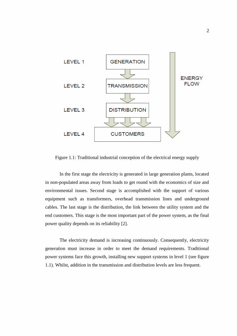
Figure 1.1: Traditional industrial conception of the electrical energy supply
In the first stage the electricity is generated in large generation plants, located
in non-populated areas away from loads to get round with the economics of size and
environmental issues. Second stage is accomplished with the support of various
equipment such as transformers, overhead transmission lines and underground
cables. The last stage is the distribution, the link between the utility system and the
end customers. This stage is the most important part of the power system, as the final
power quality depends on its reliability [2].
The electricity demand is increasing continuously. Consequently, electricity
generation must increase in order to meet the demand requirements. Traditional
power systems face this growth, installing new support systems in level 1 (see figure
1.1). Whilst, addition in the transmission and distribution levels are less frequent.
3
1.2 New Concept of Power Systems
Nowadays, the technological evolution, environmental policies, and also the
expansion of the finance and electrical markets, are promoting new conditions in the
sector of the electricity generation [2].
New technologies allow the electricity to be generated in small sized plants.
Moreover, the increasing use of renewable sources in order to reduce the
environmental impact of power generation leads to the development and application
of new electrical energy supply schemes.
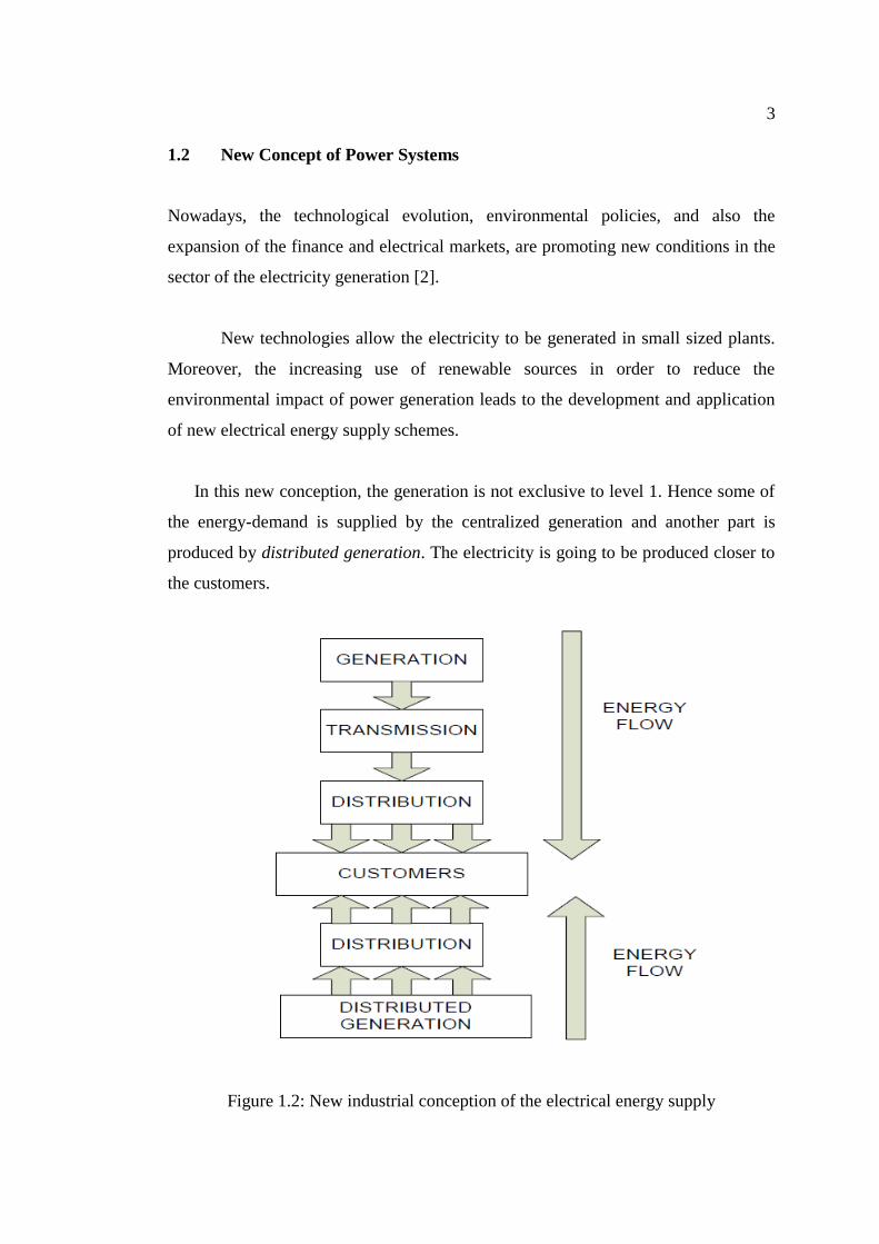
In this new conception, the generation is not exclusive to level 1. Hence some of
the energy-demand is supplied by the centralized generation and another part is
produced by distributed generation. The electricity is going to be produced closer to
the customers.
Figure 1.2: New industrial conception of the electrical energy supply
4
1.3 Distributed Generation
Trends in energy consumption requirements, and in the evolution of electricity
generation and storage technologies, will ultimately fuel a boom DG, a solution that
offers the best long-term answer to questions of reliability, price, and pollution. DG
is generally defined as generation, storage, or devices that are connected to, or
injected into, the distribution lines of the electricity grid. They may be located at a
customer‟s premises on either side of the meter or may be located at other points on
the distribution line, such as a utility substation [1]. DG is integrated with different
sizes and different technologies at distribution levels. The planning of electric
systems with the presence of DG requires the definition of several factors, such as:
the best technology to be used, the number and capacity of the units, the best
location, the network connection way, etc. Large scale integration of distributed
generators at either LV or MV is at the present the trend followed in power systems
to cover the supply of some loads. These generators are of considerable smaller size
than the traditional generators (thermal, nuclear, etc…) [3]. An overview of some
common benefits and drawbacks of the DG are presented below:
(a) Benefits [4]
i. Connection of DG is intended to increase the reliability of power supply
provided to the customers, using local sources, and if possible, reduce the
losses of the transmission and distribution systems.
ii. The connection of DG to the power system could improve the voltage profile,
power quality and support voltage stability. Therefore, the system can
withstand higher loading situations.
iii. The installation of DG takes less time and payback period. Many countries
are subsidizing the development of renewable energy projects through a
5
portfolio obligation and green power certificates. This incentives investment
in small generation plants.
iv. Some DG technologies have low pollution and good overall efficiencies like
combined heat and power (CHP) and micro-turbines. Besides, renewable
energy based DG like photovoltaic and wind turbines contribute to the
reduction of greenhouse gases.
(b) Drawbacks [4]
i. Many DG are connected to the grid via power converters, which injects
harmonics into the system.
ii. The connection of DG might cause over-voltage, fluctuation and unbalance of
the system voltage if coordination with the utility supply is not properly
achieved.
iii. Depending on the network configuration, the penetration level and the nature
of the DG technology, the power injection of DG may increase the power
losses in the distribution system.
iv. Short circuit levels are changed when a DG is connected to the network.
Therefore, relay settings should be changed and if there is a disconnection of
DG, relay should be changed back to its previous state.
1.4 Problem Statements
In Sabah, the total generation capacity of Sabah Electricity Sdn. Bhd. (SESB) is
866.4 MW. 50.3% of the total units generated are purchased from the independent
power producers (IPP). SESB installed capacity excluding IPP, of the Sabah Grid
6
which supplies electricity for major towns from Federal Territory Labuan to Tawau
is 430.9 MW and the maximum demand is 760 MW.
The East Coast Grid 132kV Transmission Line connecting the major towns in
the East Coast has an installed capacity of 333.02MW and the maximum demand is
203.3MW. The forecast demand growth of electricity is in a region of 7.7% per
annum up to the year 2010 and the electricity demand is expected to reach 1,500
MW by the year 2020. In order to support the growing demand, various generations,
transmission and distribution projects will be implemented. A fully integrated grid
connecting the West Coast Grid to the East Coast Grid was completed on 2007, and
about 90% of the customers are now connected to this integrated grid.
However, electricity interruption is one of the major problems that always
been criticized by users in Sabah. At the end of September 2013 More than 500,000
consumers in Sabah and Labuan has been affected due to the insufficient generation
power injected to grid while restoration works were being carried out by the three
Independent Power Producer (IPP) stations in Sepanggar. Because of the unexpected
incidents, SESB has been carried out staggered rationing for about one month, up to
three hours on working days.
From this problem, it is a perfect time for SESB to consider applying a new
technology that even more reliable called Distributed Generation scheme. DG could
be considered as one of the most viable options to ease some of the problems (e.g.
high loss, low reliability, poor power quality and congestion in transmission systems)
faced by power systems, apart from meeting the energy demand of ever growing
loads. In addition, the modular and small size of the DG will facilitate the planner to
install it in a shorter time frame compared to the conventional solution. It would be
more beneficial to install in a more decentralized environment where there is a larger
uncertainty in demand and supply.
However, given the choices, they need to be placed in appropriate locations
with suitable sizes. Therefore, analysis tools are needed to be developed to examine
7
locations and the sizing of such DG installations. Thus, this project modified the
economic dispatch method to determine the optimum size and location of DG in the
distribution network, and to analyze the impact of DG in term of power losses and
voltage profile.
1.5 Project Objectives
The major objective of this project is to perform a system study on the impact of load
losses and voltage stability when connected to DG in different scenarios.
Its measurable objectives are as follows:
i. The main objective of this project is to present a simulation approach to study
about distributed generation in term of to identify and determine the suitable
size and location to install DG.
ii. The second objective is to analyse the impact of applying DG to the existing
network in term of power losses and voltage profile in SESB distribution
systems.
1.6 Project Scopes
The scopes of this project are:
i. To analysing the proper size and location to install DG in distribution system
using PSS ADEPT.
ii. To analysing the impact of system losses and voltage profile when DG
applied in the existing system. The system develop in this project has been
limited to PPU Batu Sapi, Sandakan region only through Sabah Electricity
Sdn Bhd (SESB) data without any segmentation of countries and localization.
8
1.7 Outline of the Report
This report contains 5 chapters and appendices. It is organized as follows:
Chapter 1: Introduction
This chapter gives a brief introduction to the concept of distributed generation
reflecting the importance of DG systems to both the utility network and customers,
besides the drawbacks occurring if DG is connected to the distribution systems.
Chapter 2: Literature Review
This chapter is divided into six sections: the first section is a brief introduction and a
definition of DG, followed by the second section which discusses the various types
of distributed generation technologies and their nature. The impacts of DG on power
system grids are discussed in the third section. Section four high lights one of the
most important issues to maintain a safe operation of the DG, the protection
coordination. Section five is an overview of one of the major problems, islanding,
that miss-protection can lead to and causes difficulties in system restoration. Finally
the last section discusses the previous study about DG made by other.
Chapter 3: Methodology
This chapter is to present the method proposed to do the analysis about DG in terms
of load power flow, voltage stability, active and reactive power losses.
Chapter 4: Results and Discussions
In this chapter, simulations results with different DG configurations are presented.
Software used for simulation is PSS ADEPT.
9
Chapter 5: Conclusions and Recommendations
Some conclusions are presented in this chapter. The chapter ends naming some of the
works that can be done in the future with reference to the work presented in this
research.
10
CHAPTER 2
LITERATURE REVIEW
2.1 Introduction
Distributed Generation (DG) is one of the new trends in power systems used to support
the increased energy-demand. There is not a common accepted definition of DG as the
concept involves many technologies and applications. Different countries use different
notations like “embedded generation”, “dispersed generation” or “decentralized
generation”.
Furthermore, there are variations in the definition proposed by different
organizations (IEEE, CIGRE…) that may cause confusion. Therefore in this project, the
following definition is used [8]:
Distributed generation is considered as an electrical source connected to the power
system, in a point very close to/or at consumer´s site, which is small enough compared
with the centralized power plants.
To clarify about the DG concept, some categories that define the size of the
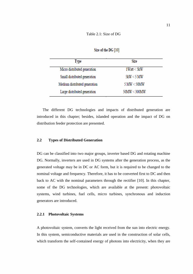
generation unit are presented in Table 2.1.
11
Table 2.1: Size of DG
The different DG technologies and impacts of distributed generation are
introduced in this chapter; besides, islanded operation and the impact of DG on
distribution feeder protection are presented.
2.2 Types of Distributed Generation
DG can be classified into two major groups, inverter based DG and rotating machine
DG. Normally, inverters are used in DG systems after the generation process, as the
generated voltage may be in DC or AC form, but it is required to be changed to the
nominal voltage and frequency. Therefore, it has to be converted first to DC and then
back to AC with the nominal parameters through the rectifier [10]. In this chapter,
some of the DG technologies, which are available at the present: photovoltaic
systems, wind turbines, fuel cells, micro turbines, synchronous and induction
generators are introduced.
2.2.1 Photovoltaic Systems
A photovoltaic system, converts the light received from the sun into electric energy.
In this system, semiconductive materials are used in the construction of solar cells,
which transform the self-contained energy of photons into electricity, when they are
12
exposed to sun light. The cells are placed in an array that is either fixed or moving to
keep tracking the sun in order to generate the maximum power [9].
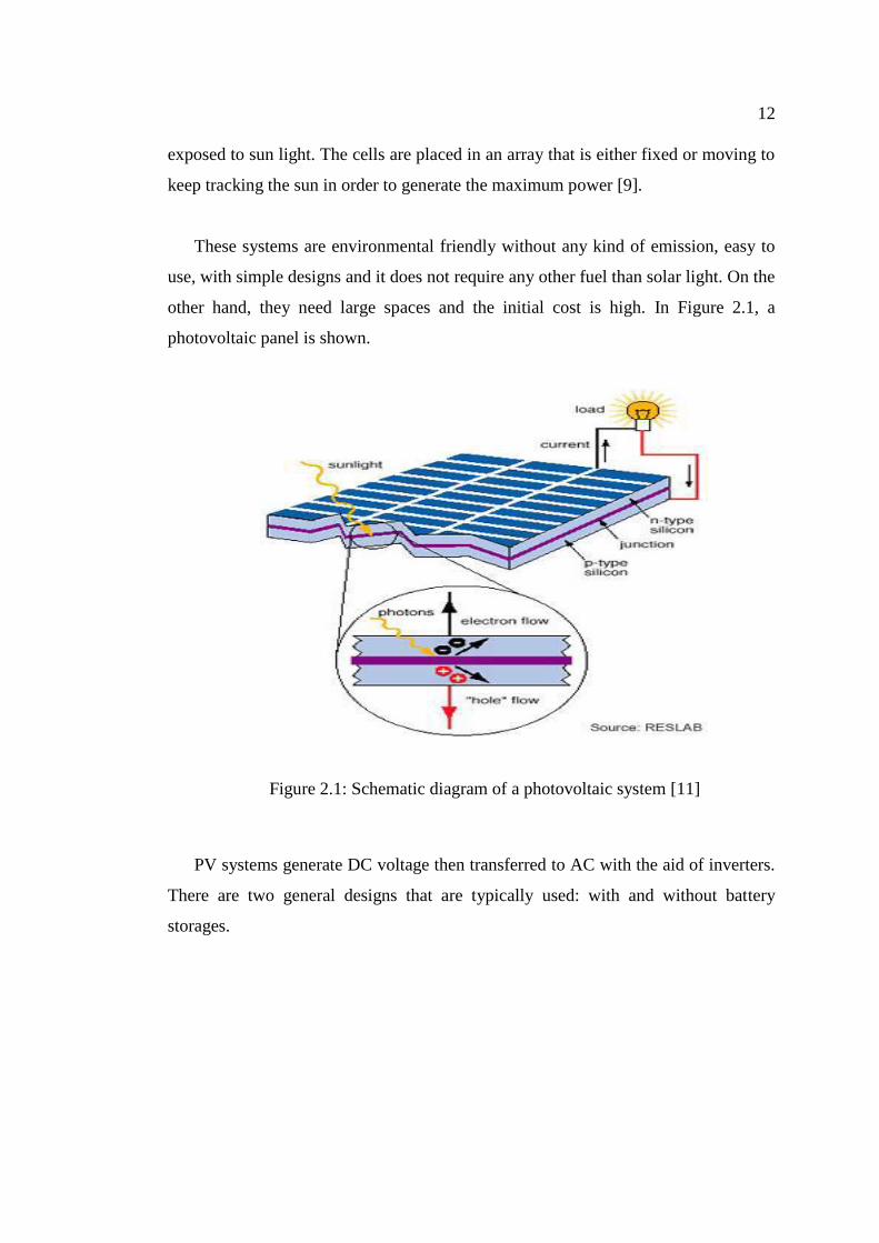
These systems are environmental friendly without any kind of emission, easy to
use, with simple designs and it does not require any other fuel than solar light. On the
other hand, they need large spaces and the initial cost is high. In Figure 2.1, a
photovoltaic panel is shown.
Figure 2.1: Schematic diagram of a photovoltaic system [11]
PV systems generate DC voltage then transferred to AC with the aid of inverters.
There are two general designs that are typically used: with and without battery
storages.
13
2.2.2 Wind Turbines
Wind turbines transform wind energy into electricity. The wind is a highly variable
source, which cannot be stored, thus, it must be handled according to this
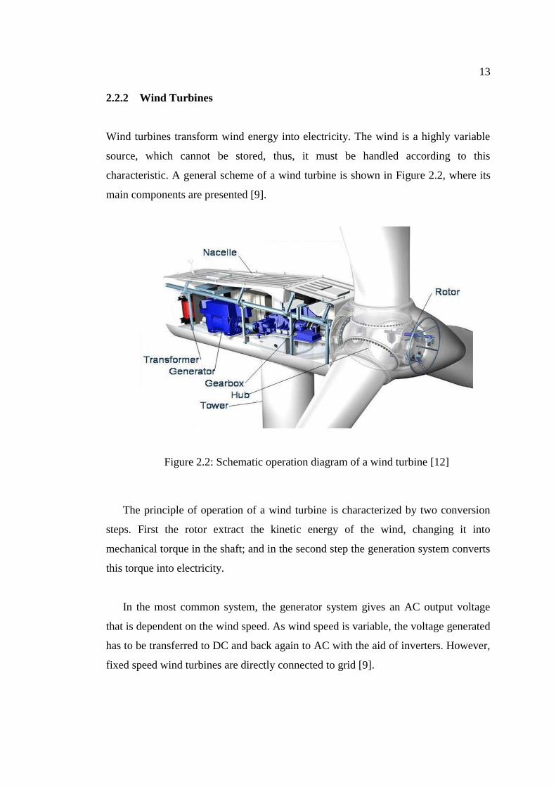
characteristic. A general scheme of a wind turbine is shown in Figure 2.2, where its
main components are presented [9].
Figure 2.2: Schematic operation diagram of a wind turbine [12]
The principle of operation of a wind turbine is characterized by two conversion
steps. First the rotor extract the kinetic energy of the wind, changing it into
mechanical torque in the shaft; and in the second step the generation system converts
this torque into electricity.
In the most common system, the generator system gives an AC output voltage
that is dependent on the wind speed. As wind speed is variable, the voltage generated
has to be transferred to DC and back again to AC with the aid of inverters. However,
fixed speed wind turbines are directly connected to grid [9].
14
2.2.3 Fuel Cells
Fuel cells operation is similar to a battery that is continuously charged with a fuel gas
with high hydrogen content; this is the charge of the fuel cell together with air, which
supplies the required oxygen for the chemical reaction [9].
The fuel cell utilizes the reaction of hydrogen and oxygen with the aid of an
ion conducting electrolyte to produce an induced DC voltage. The DC voltage is
converted into AC voltage using inverters and then is delivered to the grid. In Figure
2.3 the operation characteristics of a fuel cell are presented.
Figure 2.3: Schematic diagram of a fuel cell [13]
A fuel cell also produces heat and water along with electricity but it has a high
running cost, which is its major disadvantage. The main advantage of a fuel cell is
that there are no moving parts, which increase the reliability of this technology and
no noise is generated. Moreover, they can be operated with a width spectrum of
fossil fuels with higher efficiency than any other generation device. On the other
15
hand, it is necessary to assess the impact of the pollution emissions and ageing of the
electrolyte characteristics, as well as its effect in the efficiency and life time of the
cell [10].
2.2.4 Micro-Turbines
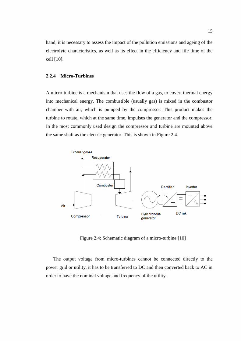
A micro-turbine is a mechanism that uses the flow of a gas, to covert thermal energy
into mechanical energy. The combustible (usually gas) is mixed in the combustor
chamber with air, which is pumped by the compressor. This product makes the
turbine to rotate, which at the same time, impulses the generator and the compressor.
In the most commonly used design the compressor and turbine are mounted above
the same shaft as the electric generator. This is shown in Figure 2.4.
Figure 2.4: Schematic diagram of a micro-turbine [10]
The output voltage from micro-turbines cannot be connected directly to the
power grid or utility, it has to be transferred to DC and then converted back to AC in
order to have the nominal voltage and frequency of the utility.
16
The main advantage of micro-turbines is the clean operation with low
emissions produced and good efficiency. On the other hand, its disadvantages are the
high maintenance cost and the lack of experience in this field. Very little micro-
turbines have been operated for enough time periods to establish a reliable field
database. Furthermore, methods of control and dispatch for a large number of micro
turbines and selling the remaining energy have not been developed yet [10].
2.2.5 Induction and Synchronous Generators
Induction and synchronous generators are electrical machines which convert
mechanic energy into electric energy then dispatched to the network or loads.
Induction generators produce electrical power when their shaft is rotated faster than
the synchronous frequency driven by a certain prime mover (turbine, engine). The
flux direction in the rotor is changed as well as the direction of the active currents,
allowing the machine to provide power to the load or network to which it is
connected. The power factor of the induction generator is load dependent and with an
electronic controller its speed can be allowed to vary with the speed of the wind. The
cost and performance of such a system is generally more attractive than the
alternative systems using a synchronous generator [14].
The induction generator needs reactive power to build up the magnetic field,
taking it from the mains. Therefore, the operation of the asynchronous machine is
normally not possible without the corresponding three-phase mains. In that case,
reactive sources such as capacitor banks would be required, making the reactive
power for the generator and the load accessible at the respective locations. Hence,
induction generators cannot be easily used as a backup generation unit, for instance
during islanded operation [14].
The synchronous generator operates at a specific synchronous speed and
hence is a constant-speed generator. In contrast with the induction generator, whose
operation involves a lagging power factor, the synchronous generator has variable
17
power factor characteristic and therefore is suitable for power factor correction
applications. A generator connected to a very large (infinite bus) electrical system
will have little or no effect on its frequency and voltage, as well as, its rotor speed
and terminal voltage will be governed by the grid.
Normally, a change in the field excitation will cause a change in the operating
power factor, whilst a change in mechanical power input will change the
corresponding electrical power output. Thus, when a synchronous generator operates
on infinite busbars, over-excitation will cause the generator to provide power at
lagging power factor and during under-excitation the generator will deliver power at
leading power factor [15]. Thus, synchronous generator is a source or sink of reactive
power. Nowadays, synchronous generators are also employed in distribution
generator systems, in thermal, hydro, or wind power plants. Normally, they do not
take part in the system frequency control as they are operated as constant power
sources when they are connected in low voltage level. These generators can be of
different ratings starting from kW range up to few MW ratings [16].
2.3 Impact of Distributed Generation on Power System Grids
The introduction of DG in systems originally radial and designed to operate without
any generation on the distribution system, can significantly impact the power flow
and voltage conditions at both, customers and utility equipment.
These impacts can be manifested as having positive or negative influence,
depending on the DG features and distribution system operation characteristics [3]. A
method to asses this impact, is based on investigate the behavior of an electric
system, with and without the presence of DG. In that sense, a general view of the
main problems encountered in the integration of DG to the distributed network is
presented.
18
2.3.1 Impact of DG on Voltage Regulation
Radial distribution systems regulate the voltage by the aid of load tap changing
transformers (LTC) at substations, additionally by line regulators on distribution
feeders and shunt capacitors on feeders or along the line. Voltage regulation is based
on one way power flow where regulators are equipped with line drop compensation.
The connection of DG may result in changes in voltage profile along a feeder
by changing the direction and magnitude of real and reactive power flows.
Nevertheless, DG impact on voltage regulation can be positive or negative depending
on distribution system and distributed generator characteristics as well as DG
location [3].
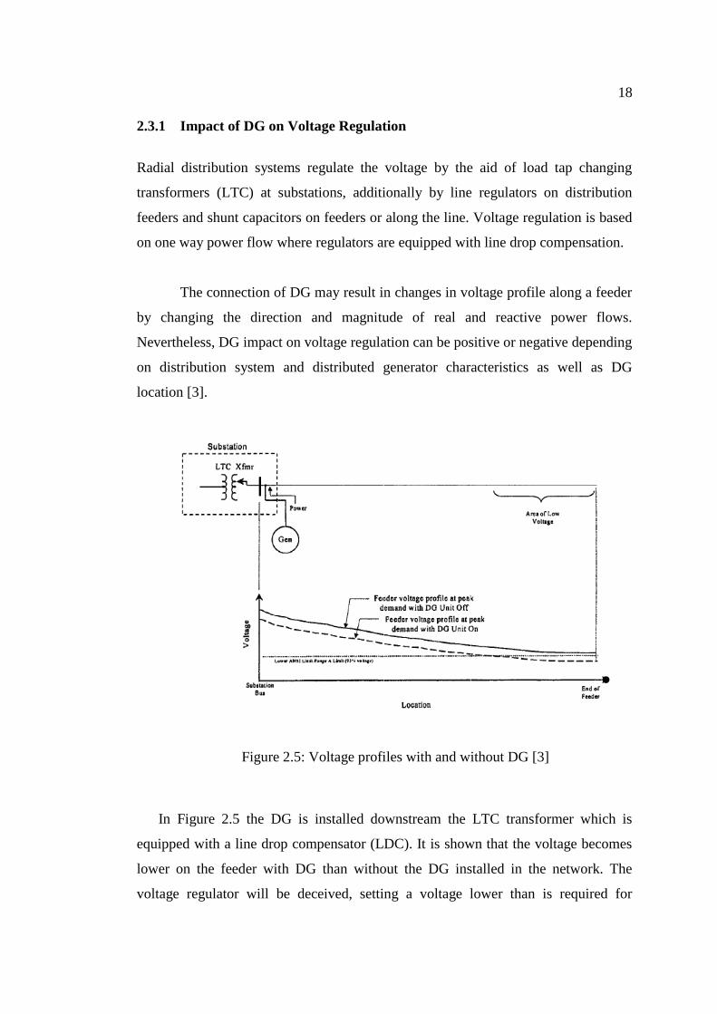
Figure 2.5: Voltage profiles with and without DG [3]
In Figure 2.5 the DG is installed downstream the LTC transformer which is
equipped with a line drop compensator (LDC). It is shown that the voltage becomes
lower on the feeder with DG than without the DG installed in the network. The
voltage regulator will be deceived, setting a voltage lower than is required for
19
sufficient service. The DG reduces the load observed from the load compensation
control side, which makes the regulator to set less voltage at the end of the feeder.
This phenomenon has the opposite effect to which is expected with the introduction
of DG (voltage support) [3].
There are two possible solutions facing this problem: the first solution is to move
the DG unit to the upstream side of the regulator, while the second solution is adding
regulator controls to compensate for the DG output.
The installation of DG units along the power distribution feeders may cause
overvoltage due to too much injection of active and reactive power. For instance, a
small DG system sharing a common distribution transformer with several loads may
raise the voltage on the secondary side, which is sufficient to cause high voltage at
these customers [3]. This can happen if the location of the distribution transformer is
at a point on the feeder where the primary voltage is near or above the fixed limits.
During normal operation conditions, without DG, voltage received at the load
terminals is lower than the voltage at the primary of the transformer. The connection
of DG can cause a reverse power flow, maybe even raising the voltage somewhat,
and the voltage received at the customer´s site could be higher than on the primary
side of the distribution transformer.
For any small scale DG unit (< 10MW) the impact on the feeder primary is
negligible. Nonetheless, if the aggregate capacity increases until critical thresholds,
then voltage regulation analysis is necessary to make sure that the feeder voltage will
be fixed within suitable limits [3].
20
2.3.2 Impact of DG on Losses
One of the major impacts of Distributed generation is on the losses in a feeder.
Locating the DG units is an important criterion that has to be analyzed to be able to
achieve a better reliability of the system with reduced losses [3].
According to [3], locating DG units to minimize losses is similar to locating
capacitor banks to reduce losses. The main difference between both situations is that
DG may contribute with active power and reactive power (P and Q). On the other
hand, capacitor banks only contribute with reactive power flow (Q). Mainly,
generators in the system operate with a power factor range between 0.85 lagging and
unity, but the presence of inverters and synchronous generators provides a
contribution to reactive power compensation (leading current) [15].
The optimum location of DG can be obtained using load flow analysis software,
which is able to investigate the suitable location of DG within the system in order to
reduce the losses. For instance: if feeders have high losses, adding a number of small
capacity DGs will show an important positive effect on the losses and have a great
benefit to the system. On the other hand, if larger units are added, they must be
installed considering the feeder capacity boundaries [3]. For example: the feeder
capacity may be limited as overhead lines and cables have thermal characteristic that
cannot be exceed.
Most DG units are owned by the customers. The grid operators cannot decide the
locations of the DG units. Normally, it is assumed that losses decrease when
generation takes place closer to the load site. However, as it was mentioned, local
increase in power flow in low voltage cables may have undesired consequences due
to thermal characteristics [4].
21
2.3.3 Impact of DG on Harmonics
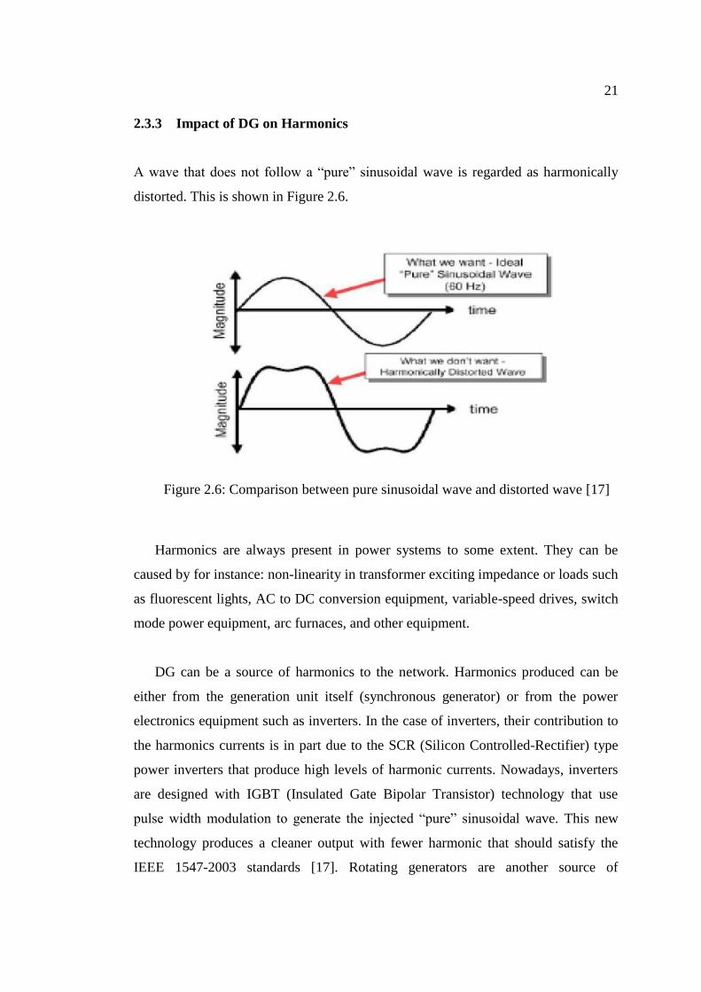
A wave that does not follow a “pure” sinusoidal wave is regarded as harmonically
distorted. This is shown in Figure 2.6.
Figure 2.6: Comparison between pure sinusoidal wave and distorted wave [17]
Harmonics are always present in power systems to some extent. They can be
caused by for instance: non-linearity in transformer exciting impedance or loads such
as fluorescent lights, AC to DC conversion equipment, variable-speed drives, switch
mode power equipment, arc furnaces, and other equipment.
DG can be a source of harmonics to the network. Harmonics produced can be
either from the generation unit itself (synchronous generator) or from the power
electronics equipment such as inverters. In the case of inverters, their contribution to
the harmonics currents is in part due to the SCR (Silicon Controlled-Rectifier) type
power inverters that produce high levels of harmonic currents. Nowadays, inverters
are designed with IGBT (Insulated Gate Bipolar Transistor) technology that use
pulse width modulation to generate the injected “pure” sinusoidal wave. This new
technology produces a cleaner output with fewer harmonic that should satisfy the
IEEE 1547-2003 standards [17]. Rotating generators are another source of
22
harmonics, that depends on the design of the generators winding (pitch of the coils),
core non-linearity's, grounding and other factors that may result in significant
harmonics propagation [3].
When comparing different synchronous generator pitches the best configuration
encountered is with a winding pitch of 2/3 as they are the least third harmonic
producers. Third harmonic is additive in the neutral and is often the most prevalent.
On the other hand, 2/3 winding pitch generators have lower impedance and may
cause more harmonic currents to flow from other sources connected in parallel with
it. Thus, grounding arrangement of the generator and step-up transformer will have
main impact on limiting the feeder penetration of harmonics. Grounding schemes can
be chosen to remove or decrease third harmonic injection to the utility system. This
would tend to confine it to the DG site only.
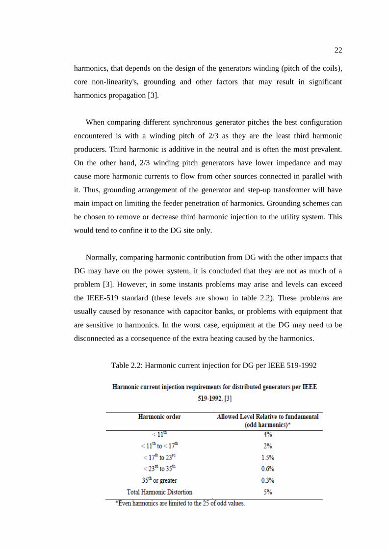
Normally, comparing harmonic contribution from DG with the other impacts that
DG may have on the power system, it is concluded that they are not as much of a
problem [3]. However, in some instants problems may arise and levels can exceed
the IEEE-519 standard (these levels are shown in table 2.2). These problems are
usually caused by resonance with capacitor banks, or problems with equipment that
are sensitive to harmonics. In the worst case, equipment at the DG may need to be
disconnected as a consequence of the extra heating caused by the harmonics.
Table 2.2: Harmonic current injection for DG per IEEE 519-1992
23
The design of a DG installation should be reviewed to determine whether
harmonics will be confined within the DG site or also injected into the utility system.
In addition, the installation needs to fulfill the IEEE-519 standard. According to [3],
any analysis should consider the impact of DG currents on the background utility
voltage distortion levels. The limits for utility system voltage distortion are 5% for
THD (total harmonic distortion) and 3% for any individual harmonic.
2.3.4 Impact of DG on Short Circuit Levels of the Network
The presence of DG in a network affects the short circuit levels of the network. It
creates an increase in the fault currents when compared to normal conditions at
which no DG is installed in the network [3]. The fault contribution from a single
small DG is not large, but even so, it will be an increase in the fault current. In the
case of many small units, or few large units, the short circuits levels can be altered
enough to cause miss coordination between protective devices, like fuses or relays.
The influence of DG to faults depends on some factors such as the generating
size of the DG, the distance of the DG from the fault location and the type of DG.
This could affect the reliability and safety of the distribution system. In the case of
one small DG embedded in the system, it will have little effect on the increase of the
level of short circuit currents. On the other hand, if many small units or a few large
units are installed in the system, they can alter the short circuit levels sufficient to
cause fuse-breaker miss-coordination. This could affect the reliability and safety of
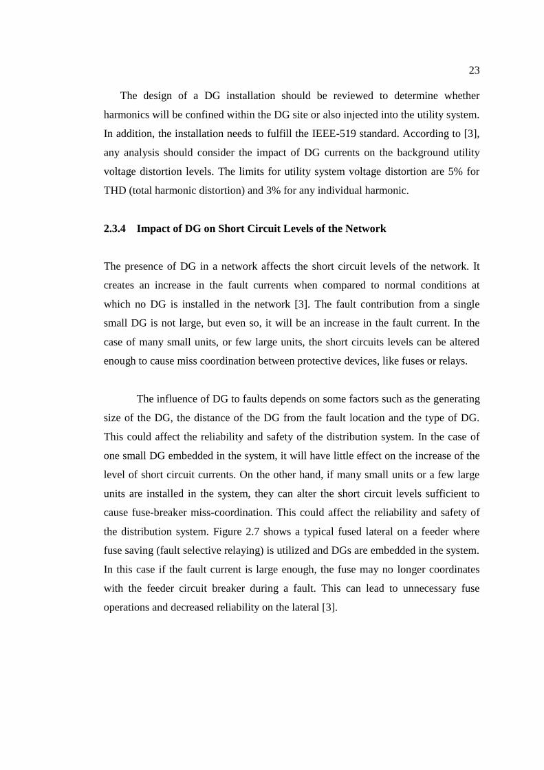
the distribution system. Figure 2.7 shows a typical fused lateral on a feeder where
fuse saving (fault selective relaying) is utilized and DGs are embedded in the system.
In this case if the fault current is large enough, the fuse may no longer coordinates
with the feeder circuit breaker during a fault. This can lead to unnecessary fuse
operations and decreased reliability on the lateral [3].
24
Figure 2.7: Fault contributions due to DG units 1, 2 and 3 are embedded in the
system. Fuse-breaker coordination may be no longer achieved
If the DG is located between the utility substation and the fault, a decrease in
fault current from the utility substation may be observed. This decrease needs to be
investigated for minimum tripping or coordination problems. On the other hand, if
the DG source (or combined DG sources) is strong compared to the utility substation
source, it may have a significant impact on the fault current coming from the utility
substation. This may cause fail to trip, sequential tripping, or coordination problems
[17].
The nature of the DG also affects the short circuit levels. The highest
contributing DG to faults is the synchronous generator. During the first few cycles its
contribution is equal to the induction generator and self-excited synchronous
generator, while after the first few cycles the synchronous generator is the most fault
current contributing DG type. The DG type that contributes the least amount of fault
current is the inverter interfaced DG type, in some inverter types the fault
contribution lasts for less than one cycle. Even though a few cycles are a short time,
55
REFERENCES
1. K Kauhaniemi, L. K. (2004). Impact of Distributed Generation on the
Protection of Distribution Networks. „University of Vaasa, Finland, VTT
Technical Research Centre of Finland, Finland.
2. Mario Vignolo, R. Z. (2002). Transmission Networks or Distributed
Generation. Montevideo, Uruguay.
3. Philip P. Barker, R. W. (2000). Determining the Impact of Distributed
Generation on Power Systems: Part 1 - Radial Distribution Systems. 12.
IEEE. Retrieved 02 16, 2011, from IEEE.
4. Vu Van Thong, J. D. (2004, January). Interconnection of Distributed
Generators and Their Influences on Power System. Katholieke Univeristeit
Leuven, Belgium.
5. E. V. Mgaya, Z. M. (2007). The Impact of Connecting Distributed Generation
to the Distribution System. Czech Technical University.
6. Falcão, C. L. (2003, June). Impact of Distributed Generation Allocation and
Sizing on Reliability, Losses and Voltage Profile. Bologna, Italy.
7. J.Holmes, J. M. (2004). Protection of Electricity Distribution Networks.
United Kingdom: Power and Energy Series 47.
8. C.Fortoul, F. G.-L. (2005). Review of Distribued Generation Concept:
Attemp of Unification. Porceding of International Conference on Renewable
Energies and Power Quality, España.
56
9. N. Hatziargyriou, M. D. (2000, November). Cigre technical brochure on
Modeling New Forms of Generation and Storage.
10. Gonzalez-Longatt, F. M. (2008, Junio). Impacto de la Generación Distribuida
en el Comportamiento de los Sistemas de Potencia. Universidad Central de
Venezuela.
11. Ingenieros, A. M. (2011). grupoglobalgreen. Retrieved May 20, 2011, from
grupoglobalgreen: www.grupoglobalgreen.es.
12. tutorvista. (n.d.). Retrieved February 18, 2011, from tutorvista:
http://www.tutorvista.com/physics/wind-electric-power.
13. Energy OR Technologies Inc. (n.d.). Retrieved February 15, 2011, from
Energy OR Technologies Inc:
http://www.energyor.com/energyor/fuel_cell.cfm.
14. Fladerer, T. (2004, March). The Asynchronous Generator in Small Power
Plants. Ruhstorf.
15. Chan, T.-F. (2003). SYNCHRONOUS MACHINES. Encyclopedia of Life
Support Systems, Polythecnic University, HONG KONG.
16. Walmir Freitas, J. C. (2006, February). Comparative Analysis Between
Synchronous and Induction Machines for Distributed Generation
Applications. IEEE Transaction on Power Systems.
17. Khan, U. N. (2008). Impact of Distributed Generation on Distributed
Network. Wroclav, University of Technology, Poland.
18. Martin-Arnedo, J. A. (2009, October). Impacts of Distributed Generation on
Protection and Power Quality.
57
19. M. Gandomkar, M. Vakilian, M. Ehsan, “Optimal distributed generation
allocation in distribution network using Hereford Ranch algorithm”,
Proceedings of the Eighth International Conference on Electrical Machines
and Systems, 2005. Volume 2, Issue, 27-29 Sept. 2005, pp. 916-918.
20. T. Gozel, U. Eminoglu, M.H. Hocaoglu, “A tool for voltage stability and
optimization (VS&OP) in radial distribution systems using matlab graphical
user interface (GUI)”, Simulation Modelling Practice and Theory 16 (2008),
pp 505-518, Elsevier, February 2008
21. T. Gozel, M.H. Hocaoglu, “An analytical method for the sizing and siting of
distributed generators in radial systems”, Electric Power Systems Research,
2008
22. Huang, F.-S. P.-J. ( 2001, December). A Detection Algorithm for Islanding-
Prevention of Dispersed Consumer-Owned Storage and Generating Units.
IEEE.
23. Pukar Mahat, Z. C.-J. (2008, April). Review of Islanding Detection Methods
for Distributed Generation
24. Ng H.N., Salama M.M.A. and Chikhani A.Y. ,“Capacitor allocation by
approximate reasoning: fuzzy capacitor placement”, IEEE Transactions on
Power Delivery, vol. 15, no.1, pp 393 – 398, January 2000.
25. Vladimiro Miranda, J.V. Ranito, L. M. Proenca, “Genetic Algorithms in
Optimal Multistage Distribution Network Planning”, IEEE Trans. Power
Systems, Vol. 9, no. 4, Nov. 1994, 1927-1933.
26. Rakesh Ranjan and Das, “Simple and efficient Computer algorithm to solve
Radial Distribution Networks”, Electric Power components and Systems,
31:95-107,2003.
58
27. K.Prakash and M. Sydulu „A Novel Approach for Optimal Location and
Sizing of Capacitors on Radial Distribution Systems Using Loss Sensitivity
Factors and -Coefficients‟, IEEE PSCE, 2006.
28. Damodar Reddy M. and Veera Reddy V.C., “optimal capacitor placement
using fuzzy and real coded genetic algorithm for maximum savings” Journal
of Theoretical and Applied Information Technology,Vol-4, No-3, p.p 219-
226, March – 2008.
29. Das D., Kothari D.P. and Kalam A., “Simple and efficient method for load
flow solution of radial distribution networks”, Electrical Power & Energy
Systems, vol. 17, no. 5, pp. 335-346,1995.
30. Baran M. E. and Wu F. F., “Network reconfiguration in distribution systems
for loss reduction and load balancing,” IEEE Transactions on Power
Systems., vol. 4, no. 3, pp. 1401–1407, Aug. 1989.
31. Baran M.E. and Wu F.F., “Optimal capacitor placement on radial
distribution systems”, IEEE Transactions on Power Delivery, vol.4
32. S.S. Rao, Engineering Optimization: Theory and Practice, third ed., Wiley-
Interscience, New York, 1996.
33. M. F. Alhajri, M. R. Alrashidi and M. E. EL-Hawary, “Improved Sequential
Quadratic Programming Approach for Optimal Distribution Generation
Deployments via Stability and Sensitivity Analyses”, Electric Power
Components and Systems, 38, pp 1595-1614, 2010
Recommended


![NA27 in SESB 1.0. A first lookrosetta.reltech.org/TC/vol11/SESB2006rev.pdf[23 August 2005] [SESB NA27 apparatus review for TC.wpd] 1 NA27 in SESB 1.0. A first look Jan Krans, reviewer](https://img.pdfslide.net/doc/110x75/60abaa73eea4221f824237e3/na27-in-sesb-10-a-first-23-august-2005-sesb-na27-apparatus-review-for-tcwpd.jpg)