IN
~OF
)TI
7' ;4LCT
DEATETO H I OC
AIR UNIERIT
AIRs~~ FOC NTIUEO TCNLG
Wrigt-Pateron Ar Foce aseOhi
Fal 17 22w

AFIT/GLM/LSM/88S-5
AIRCRAFT SCHEDULED STRUCTURAL MAINTENANCEPROGRAMS: CURRENT PHILOSOPHIES AND METHODS INTHE UNITED STATES AND THEIR APPLICABILITY TO THE
ROYAL AUSTRALIAN AIR FORCE
THESIS
George W. Breen, BE
Flight Lieutenant, RAAF
AFIT/GL M/LSM/88S -5
Approved for public release; distribution unlimited.

The contents of the document are technically accurate, and nosensitive items, detrimental ideas, or deleterious information iscontained therein. Furthermore, the views expressed in thedocument are those of the author and do not necessarily reflectthe views of the School of Systems and Logistics, the AirUniversity, the United States Air Force, or the Department ofDefense.
Aocession For
NTIS GRA&IDTIC TABUnannounced 0lJustification
ByDistribution/
Availability CodesAvai'l and/or 7
Dist SpecialAuI

AFIT/GLM/LSM/88S-5
AIRCRAFT SCHEDULED STRUCTURAL MAINTENANCE PROGRAMS:
CURRENT PHILOSOPHIES AND METHODS IN THE UNITED STATES
AND THEIR APPLICABILITY TO THE ROYAL AUSTRALIAN AIR FORCE
THESIS
Presented to the Faculty of the
School of Systems and Logistics
of the Air Force Institute Of Technology
Air University
In Partial Fulfillment of the
Requirements for the Degree of
Master of Science in Logistics Management
George W. Breen, BE
Flight Lieutenant, RAAF
September 1988
Approved for public release; distribution unlimited.

Preface
The purpose of this study was to determine current
structural maintenance philosophies and methodologies in use
in the United States of America (USA) and to compare these to
the current methods used by the Royal Australian Air Force
(RAAF). The RAAF last reviewed its maintenance philosophy in
the early 1970s and structural maintenance requirements have
not be covered entirely separately before.
This thesis has been rewarding in that it has
highlighted the difficulties involved in the management of
technical equipment in the absence of perfect information.
No maintenance program is ever perfect to begin with and is
rarely optimal. Maintenace programs require both technical
and managerial expertise to balance the various operational
and resource constraints against the attendant safety risk
inadequate maintenance poses. The integrated and dynamic
nature of maintenance programs is readily seen, particularly
in the commercial arena.
I wish to thank all those who gave me their time to
discuss the various aspects of structural maintenance. In
particular, I thank them for their willingness to admit that,
so far, no one solution is considered perfect.
ii

TABLE OF CONTENTS
Page
Preface.............. . . .. .. .. .. .. .. . .. .
List of Figures. ....... . ... .. ..... .. vAbstract . . . . .. .. .. .. .. .. ..... v1
I. Introduction . .. .. .. ... .. ... ... .1
Background . ................. IStatement of the Problem............3Research Questions . .. .. .. .. ... .4
Scope/Limitations. .............. 4Assumptions. .......... . . . . .5Definitions .. ................ 6
I. Background and Literature Review. ......... 8
Introduction ...................... 8Characteristics of Structural Maintenance 8
Purpose ... . .. .. 8Characteristics .... 9Usage Effects .. .. .. .. ..... 12Structural Design Philosophies . .13
Structural Maintenance Requirements . .17Regulator versus operator Requirements 19
Initial Programs. ............. 21Through Life Programs .. .......... 26Effectiveness of RCK/MSG Approaches . .31overview. ................. 33
III. Methodology. ............ .. .. .34
General Methodology .. ........... 34Specific Methodology . .. .... .. .35
Research Question 1. ......... 35Research Question 2. ......... 36Research Question 3 .. . . . . . 36Research Question 4...o.........37
IV. Findings, Comparison and Discussion . . . . 38
Introduction. ............... 38Findings ................... 38
Initial Programs . .. .o. .. .. .38
Commercial. ............ 38USAF . ............... 39USN .. ............... 41

RAAF 41Maintenance Program Reviews . . 41
Commercial . .......... .42USAF . . . . . . . . . . . . . 42USN ................ 43RAAF ............. 43
Through-Life Management ... 43Commercial . . . .......... 43us AF . . . . . . . . . . . . . 44OSN ................ 45RAAF ... ............. 46
Comparison .............. 46Philosophy. ........... 47MSG-3 Methodology.. . . . . . . . 47
Discussion ... .............. .48Additional Issues ........ .51
Integration of Fatigue Information 52MSG-4? ...... ....... 54
V. Conclusions and Recommendations ... ....... 56
Conclusions ........... 56Recommendations 56Recommendations for Further Study . . 57
Appendix A: Telephone Interview Framework . . . . 58
Appendix B: RCM - A Maintenance Philosophy . . . . 59
Appendix C: Results of Comparison BetweenMaintenance Philosophies ......... 6
Appendix D: MSG-3 Structural Methodology ..... 68
Appendix E: Results of Comparison BetweenStructural Maintenance Methodologies . 70
Appendix F: MSG-3 Structural Logic Diagram .... 71
Appendix G: Level of Analysis Diagram ...... 76
Appendix H: RAAF Decision Logic . ......... .77
Bibliography ...... ................... .81
iv

List of figures
Figure Page
1. Principle Damage Sources . . . . .......... 11
2. Structural Design Terms . . ............. 14
3. Damage Tolerance Regulation Comparison . . . . 16
4. Structural Analysis Requirementsand Maintenance-Considerations . . ...... 18
5. Comparison of Maintenance Concepts ...... 23
6. Methods for Determining or ReviewingMaintenance Programs ... ............. . 39
7. Development and Approval of Initial InspectionProgram and Change Procedure . . ....... . 40
8. Key Considerations and Responsibilitiesfor EDR and ADR Evaluation . . . . . . . .. 52
V

Abstract
This thesisrconcentrates on determining the status of
maintenance philosophy development and, in particular, on
structural maintenance methodologies. An extensive treatment
of the historical development of structural characteristics
and design methodologies which effect structural maintenance
requirements is given.
Additional support for current philosophies and
methodologies is obtained from interviews with both
commercial and military practitioners employed in managing
structural maintenance programs. These results, together
with the extensive literature review lead to the conclusion
that operators in the United States of America all subscribe
to the MSG/RCM doctrines and use the structural maintenance
methodology detailed in the MSG-3 document.
A comparison between these methods and those used by the
Royal Australian Air Force (RAAF) reveals that there is
little philosophical difference between the two, however the
methodologies vary considerably. The RAAF's procedures are
based on MSG-3's predecessor document MSG-2 which did not
have a dedicated structural maintenance methodology. ) <The report concludes that there is sufficient evidence
to supporting the effectiveness of the MSG-3 structural
methodology and, therefore, it should be adopted by the RAAF.
vi

AIRCRAFT SCHEDULED STRUCTURAL MAINTENANCE PROGRAMS:CURRENT PHILOSOPHIES AND METHODS IN THE UNITED STATES
AND THEIR APPLICABILITY TO THE ROYAL AUSTRALIAN AIR FORCE.
I. Introduction
Background
Aircraft structures have unique characteristics which
make the determination of initial scheduled and through-life
maintenance requirements difficult. In particular, aircraft
structures are one of the few aircraft systems which are
designed to last the complete lifetime of the aircraft.
Structures deteriorate due to one, or a combination, of the
following three mechanisms:
a. Fatigue accumulation,
b. Environmental corrosion, and
c. Accidental damage (17:1393,21:22).
Maintenance managers aim to provide a safe airframe
which performs at the required standard throughout its
operational life at minimum overall cost. To achieve this
goal, initial maintenance programs for new aircraft are
currently developed using a decision logic approach.
Commercial airlines use the MSG-3 approach as endorsed by
the Federal Aviation Administration (FAA) and Air Transport
1

....-.
Association's (ATA) Maintenance Steering Group (MSG).
Military organizations use a version of the same process
known as Reliability Centered Maintenance (RCM).
The MSG/RCM method provide an analytical approach to
determining maintenance tasks for new aircraft, including
structures. The main purpose of this process Is to develop
a maintenance program, for all aircraft systems including
structural assemblies, which maintains inherent levels of
safety and reliability. This method provides a default
logic which is used when the applicability or effectiveness
of a maintenance task is not known. Consequently, the
initial program developed from these methods is not optimal,
actual operating experience is required to validate and
update an initial program. In addition, management
techniques exist which can be used to smooth operational and
environmental differences across a fleet of similar
aircraft.
The Royal Australian Air Force (RAAF) use a procedure
based on MSG-2 to determine the initial maintenance program
for new aircraft. The procedures used are consistent with
the RAAF's maintenance philosophy known as the RAAF
Analytical Maintenance Policy (RAMP). The RAMP method for
the determination of maintenance tasks for aircraft
structural items is given in Reference 10 Section 5
2

Chapter 2. An analysis of the applicability of MSG-3 logic
diagrams in 1983 concluded that there appeared to be little
benefit in adopting the expanded logic diagrams of MSG-3
(29:1). Although this review did not specifically focus on
structures, It did recommend that:
The clearer logic paths could be introduced into MEAbut only after analysis by a dedicated team whensufficient data on the practical results of MSG-3 isavailable.(29:1)
After eight years of industry experience with MSG-3 in the
United States of America (USA) a review of the applicability
of current structural maintenance philosophies to the RAAF
is desireable and timely.
Statement of the Problem
RAAF staff involved with the determination of scheduled
maintenance programs are unsure of the currency of RAAF
maintenance philosophy and, in particular, the currency of
the structural methodology outlined in Reference 10.
Consequently, a review of structural maintenance
philosophies and management techniques used by military and
commercial aircraft operators in the USA would enable an
objective look at the currency of RAMP philosophies and
methodologies. Differences can then be reviewed with
respect to an updating of the RAMP philosophy.
3

Research Questions
The following research questions will be addressed to
obtain the most recent information on structural maintenance
philosophies:
1. What philosophies and methods are used by commercial
aircraft operators in the United States for managing
scheduled maintenance for aircraft structures throughout
their operational life?
2. What philosophies and methods are used by the United
States Air Force (USAF) and the United States Navy (USN) for
managing scheduled maintenance for aircraft structures
throughout their operational life?
3. Are any of the methods Identified above significantly
different to the methods detailed in RAMP or used by the
RAAF?
4. Of the differences identified, are any potentially
significant enough to warrant inclusion in RAMP or RAAF
maintenance policy?
Scope/LimitatLons
To adequately cover maintenance philosophy development
the general development of maintenance philosophies must be
determined first. Structural maintenance requirements were
initially developed in conjunction-with procedures for
aircraft systems. The unique characteristics of aircraft
structures (fatigue, corrosion etc) however, have
4

necessitated different procedures for determining scheduled
maintenance requirements than for other aircraft systems.
Thus, the broad development of aircraft maintenance
philosophies and methodologies will be covered.
Scheduled maintenance normally consists of a
maintenance task and a task interval. This thesis will only
discuss tasks and periodicity in general terms, particularly
when necessary to demonstrate a concept. It is not within
the scope of this thesis to discuss actual task
efficiencies, effectiveness or methods for determining task
intervals.
This thesis is aimed at providing a management
perspective on maintenance philosophies in an attempt to
identify opportunities for better structural maintenance
management. The technical issues involved will not be
addressed in detail.
Assumptions
Throughout the research it will be assumed that the
analysis of maintenance tasks starts with complete
manufacturers data on structurally significant items,
failure modes and effects, levels of redundancy and an items
criticality. Furthermore, it is assumed that this
information will normally be required and thus produced in
due course.
5

Definitions
Accidental Damage. Physical deterioration of an itemcaused by contact or impact with an object or influencewhich is not a part of the aircraft, or by impropermanufacturing or maintenance practices (21:33).
Age Exploration. A systematic evaluation of an itembased on analysis of collected information from in-serviceexperience. It assesses the item's resistance to adeterioration process with respect to increasing age(21:33).
Damage Tolerant. A qualification standard for aircraftstructure. An item is Judged to be damage tolerant if itcan sustain damage and the remaining structure can withstandreasonable loads without structural failure or excessivestructural deformation until the damage is detected (21:33).
Fleet Leader Concept. Inspections on specific aircraftselected from those which have the highest operatingage/usage in order to identify the first evidence ofdeterioration in their condition caused by fatigue damage(21:34).
Item. Any level of hardware assembly (i.e. system,sub-system, module, accessory, component, unit, part, etc.)(21:36).
Other Structure. Structure which is Judged not to be aStructural Significant Item. "Other Structure" is definedboth externally and internally within zonal boundaries(21:37).
Overhaul. Overhaul (OH) is a preventive maintenanceprocess performed on items 'off aircraft'. It involvessystematic disassembly, replacement or restoration of wornparts and comprehensive testing to restore the item to acondition such that it meets both specified physicaltolerances and standard and performance standards (I1:A-2).
Preventative Maintenance. Preventative maintenance isdefined as the maintenance actions that delay or prevent theoccurrence of a known failure mode (11:A-2).
Reliability-Centered Maintenance (RCM). RCM is adisciplined logic or methodology used to identifypreventative maintenance tasks to realize the inherentreliability of equipment at a minimum expenditure ofresources (13:7).
6

Safe Life Structure. Structure which is not practicalto design or qualify as damage tolerant. Its reliability isprotected by discard limits which remove items from servicebefore failures are expected (21:37).
Scheduled Maintenance Check. Any of the maintenanceopportunities which are prepackaged and are accomplished ona regular basis (21:37).
Structural Assembly. One or more structural elementswhich together provide a basic structural function (21:37).
Structural Detail. The lowest functional level in anaircraft structure. A discrete region or area of astructural element, or a boundary intersection of two ormore elements (21:37).
Structural Element. Two or more structural detailswhich together form an identified manufacturer's assemblypart (21:37).
Structural Function. The mode of action of aircraftstructure. It includes acceptance and transfer of specifiedloads in items (details/elements/assemblies) and provideconsistently adequate aircraft response and flightcharacteristics (21:38).
Structural Significant Item (SSI). A structuraldetail, structural element, or structural assembly which isJudged significant because of the reduction in aircraftresidual strength of loss of structural function which areconsequences of its failure (21:38).
TJh The specific value of a usage parameter(flight cycles, flight hours, etc.) at which the firstinspection of some particular level or method should beconducted (21:38).
7

II. Background and Literature Review
Introduction
The purpose of reviewing available literature on
aircraft structural maintenance programs is to determine the
following:
a. The characteristics of structural maintenance.
b. The evolution of structural maintenance methods.
Characteristics of Structural Maintenance
This section describes the characteristics of aircraft
structures and how these effect structural waintenance
programs.
Purpose. The purpose of an aircraft structure is to
provide the following:
a. aerodynamic lift,
b. fixed and moveable flight control surfaces (excluding
actuating mechanisms),
c. volume for crew, passengers and payload (generally
pressurised),
d. internal volume for fuel,
e. a means for transition between ground and air modes
(undercarriage),
f. mounting points for engines,
g. mounting points for other ancillary items(25:229-230).
8

Aircraft structures are normally considered as three
separate but integrated parts: the fuselage, wing, and tail-
plane. Aircraft structural performance effects the primary
mission of the aircraft. Each structural assembly and its
elements must be able to support their share of the flight
and ground loads throughout the operational flight envelope
and for the whole economic life.
Characteristics. Aircraft structural characteristics
depend on two things, the material used and the design
methodology. Design methodology is discussed later in this
section.
The wood and cloth structures of early aircraft had
quite different deterioration modes compared to the
materials commonly used today. These deterioration modes
dictate certain detail design practices to the designer;
whether an item requires a protective coating to avoid
dissimilar metal corrosion or whether the item should be
designed to be easily replaced due to poor fatigue
characteristics. Ultimately, material properties dictate
the performance limitations of the design but, more
importantly, future maintenance requirements are dictated by
these inherent characteristics. These characteristics
provide the designer with various trade-offs during the
design process which will ultimately affect the structural
integrity of the aircraft as it ages.
9

Failure of a structural assembly usually results in
flight safety consequences and therefore must be avoided.
Additionally, aircraft structures are generally difficult
and expensive to repair.
The structure is designed as an integral unit, andcorrective maintenance on any structural item removesthe entire airplane from service. Moreover, becausethe failure of any major assembly is critical, allparts of the structure are designed to survive to veryhigh ages (25:108).
Consequently, the basic airframe is designed to last the
service life of the aircraft without major repair. Safety
and economics dictate that structural failures be avoided,
however, this goal is rarely achieved due to the nature of
performance and operational cost trade-off required with
aircraft designs.
Most common aircraft structures are made from
aluminium. Aluminium aircraft structures have three
principle damage mechanisms which degrade their integrity.
They are as follows:
a. environmental deterioration, (corrosion and stress
corrosion),
b. accidental damage, (such as from manufacturing flaws,
ground handling equipment, and bird strikes), and
c. fatigue damage (caused by cyclic loading)
(17:1393,25:238).
10
I

Figure 1 shows the relationship between damage phase
and the principal parameters controlling source of damage.
PRINCIPLE PARAMETERS CONTROLLING GIVENSOURCE OF DAMAGE AID DAMAGE PHASE
DamagePhase
FATIGUE ENVIRONMENTAL ACCIDENTAL
Quality Corrosion Random DiscreteCyclic Stress -Operating Event from a
Ifniti- Operating Environment cause notation Environment -Protective System normally en-
Flight Cycles/ Stress Corrosion countered dur-Hours -Material Sensitivity ing fleet ops.
Level of SustainedTensile Stress
Material Extent of conditions Kay result inGeometry that caused damage subsequent
Growth Cyclic Stress initiation crack growthEnvironment May result in sub- if not detectFlight Cycles/ sequent crack grovth detected andHours if not detected and repaired
repaired
Figure 1 Principle Damage Sources (17:Figure 3)
Of the three sources of damage highlighted above,
environmental and accidental causes are viewed as random
occurrences. Little can be done to eliminate or predict
them. Fatigue damage on the other hand, accumulates with
usage. Most fatigue damage is accrued during flight/ground
transitions (or flight cycles) or accumulated in proportion
to a particular flight (or mission) profile. Therefore,
based on manufacturers testing, damage due to fatigue
ii

. ......... ...... I I I l ..] ..........
L
accumulation can be predicted with reasonable accuracy.
Additional accuracy can be achieved if fatigue is monitored
on a flight by flight basis for individual aircraft.
Fatigue damage can be managed through good design
practices, prototype testing, and thorough inspection
through-out an airframes life. The fatigue mechanism is
reasonably well understood, however, the exact accumulation
of damage in an aircraft structure depends on "usage
variables such as the type of mission flown, stores carried,
operating gross weight, the number of landings, pilot
techniques, etc (15:1)." Additionally, factors such as
corrosion, accidental damage, manufacturing flaws, and
maintenance practices can also affect the rate at which
damage is accumulated (25:235).
Thus, it is the aim of the aircraft designer to produce
a design which is robust in a variety of operational
scenarios. Particular attention must be paid to keeping the
anticipated stresses below the level necessary to ensure
safe operation until the economic life of the aircraft is
reached. The economic life of an aircraft is normally
governed by the structural integrity of the airframe.
Usage Effects. In the commercial and military
operating environments aircraft are used quite differently.
The stress spectra that normal commercial aircraft are
designed to is benign compared to that of the military.
12

Consequently, methods used to track airframe damage, in
particular fatigue damage, are different.
Due to the rate at which fatigue damage can be attained
in the military environment, individual aircraft can achieve
damage at rates which are not linearly related to actual
flight hours. Hence, methods which relate cumulative damage
to flight hours, particularly for non-transport aircraft,
can be very misleading.
Structural Design Philosophies. There are two
structural design philosophies which have been used for
current as well as past aircraft. These are "safe life" and
"damage tolerant". Definitions of these terms are contained
in Chapter 1, but the difference between the two can be
summarised as follows:
a. Safe life: The safe-life method first determines the
maximum number of cycles a particular item can withstand
(analytically, empirically or by full scale or coupon test)
without failure and divides this number by a scatter factor
(normally 3 or 4). Safe life assumes a defect free initial
structure.
b. Damage Tolerant: A design method which examines the
residual strength of an assembly after failure of an
element. It assesses the effect on operating safety of
having undetected failures present in a structure. Defects
are assumed to be present in the structure when
13
manufactured. This technique is also known as redundant or
fail-safe design. Figure 2 summarises the differences In
terminology.
Term Description
Safe-Life Replace at specific age regardless of condition, eg.undercarriage component.
Fail-Safe The failure of an Item is not safety or mission critical:the structure is damage toleeant.
Damage The ability of an item to perform adequately after aTolerant failure of a component. Primarily a result of redundant
design techniques.
Durability Primarily a function of the material. The ability of thematerial to perform adequately when flawed.
Figure 2: Structural Design Terms (17,21,25)
Safe-life design was used extensively up until the
acceptance of fracture mechanics .as a structural damage
analysis and decision making tool. The USAF used the Safe
life approach up until 1970. At that time damage tolerance
requirements were written into MIL-SPEC-1530 (12).
An examination of the pre - 1969/70 approach todurability and safety reveals that in the design phasethere was emphasis on initial static strength and a"safe-life" fatigue design approach was utilized withthe assumption of an initial flaw free structure.Analyses leading to mean life estimates were conductedwith a scatter factor introduced to account for suchfactors as environmental effects, material propertyvariations and initial quality variations. There wereno damage tolerance design requirements for protectionof the aircraft structure from flaws either inducedfrom in-service operation or existing in the as-delivered new structure (8:1).
The main reasons for changing the specifications from
safe-life to damage tolerant are summarised below.
14

The fixed performance and functional requirementsresulted in low weight allowances which in turn forcedthe selection of high strength fracture sensitivematerials and use of high design stress levels. In aneffort to prevent initial manufacturing flaws whichwould be catastrophic when combined with high stresslevels, it was necessary to adopt high cost materialsand manufacturing processes and quality controlprograms. Such efforts drive up program costs andexperience has shown that even the most carefulmanufacturing and quality control program will noteliminate all initial manufacturing flaws (8:1).
A number of military operational airframes which were
designed to safe-life criteria were reevaluated under these
new requirements and found to be "damage tolerant". A
damage tolerance structural analysis of an F-SE was
conducted in 1976-78 and commented that:
... while the F-5E aircraft was not specificallydesigned to the damage tolerance requirements, featureswere incorporated which have contributed to theairframe's success in meeting and exceeding itsdurability requirements and its adaptability to laterapplication of damage tolerance (22:18).
Therefore, although the design rules changed, a lot of
existing aircraft met the new requirements. The biggest
advantage in undertaking the damage tolerance analysis was
that it enabled the effect of life extensions on structural
integrity to be assessed.
Damage tolerance analysis is a logical extension offatigue analysis and is a fundamental tool inestablishing a cost effective structural maintenanceprogram as well as protecting the safety of anyoperational aircraft (22:39).
15

Whilst this activity was going on in the military area,
similar changes were made to the Federal Aviation
Regulations (FAR) which affect design methodology.
Commercial Jet transport structures have been designedand certified according to a fail-safe philosophy forover twenty years. Airframes thus have the ability tosustain maximum anticipated or fail-safe loads withsignificant structural damage; for example, wingstructures were designed to carry the full design-limitload with a skin crack extending across two stringerbays. ... This was recognized in the recent revisionof the Federal regulations for damage tolerance (FAR25.571), with which both the Boeing models 757 and 767comply (17:1393).
Figure 3, shows a comparison of the difference in
analysis methods required by FAR 25.571.
ANALYSIS OLD FAR 25.571(PRE 1978) NEV FAR 25.571(POST 1978)
Single element or Multiple active cracksobvious partial failure
RESIDUAL I. •STRENGTH
l ab
CRACK No analysis required Extensive analysisGROWTH required
Based on Service History Related to Structuraldamage characteristics
INSPECTION and past service historyPROGRAM
FAA Air carrier Initial FAA Engineeringapproval and air carrier approval
Figure 3: Damage Tolerance Regulation Comparison (19:Figure 1)
16

This change in emphasis results in the acknowledgement
that aircraft structures made from fatigue susceptible
materials eventually crack, and this may or may not have an
impact on operating safety/economics. The effect of design
method on the safety and structural maintenance is shown in
Figure 4.
Structural Maintenance Reauirements
The goal of a structural maintenance program is to
ensure the structural integrity of the airframe with the
minimum use of resources throughout the airframes useful
life. Initially, a maintenance program based on the
inherent quality of the design needs to be implemented. The
structural integrity of the airframe must be monitored
throughout its life to ensure that functional failures due
to fatigue, corrosion or accidental damage do not occur.
Maintenance programs suffer a dilemma. By the time
enough information is available to accurately determine the
maintenance program for a particular fleet of aircraft,
either usage or accumulated age changes the failure rate or
damage accrual mechanisms to the point where the program
implemented is never optimal. The maintenance program based
on actual historical data always lags the optimal program.
Maintenance is normally classified as scheduled or
unscheduled. Items which exhibit the tendency to wear-
17

u w V,
P-- u - 0
a- 9La- wI C 0a
-j ).- *2:~ a- 0w ~ 1--_cc z4 2 UJ U z~& wza Lwi z 4 g 4 0%C CAW0 -
2 0 U. =,.
o gw,( 4 WZ 40.40Mi011 40>u . LaJu 0 ~ u2
I4 a-W. 0 U. 0az 2 wj 00 2 0 z 2 <4 0- ;
oz aZ Z 2 cIzj 4 CCZ 0
mi 2040 c o mo-004-: P-2 a
4Z 3 uU.-wC 2 -1 t
3 a -04W.4 D Up z wwww0
I-a ;-
u twz*c cc 4% WW%
- 40 0 cc>-
_________ CA
a- 2'
I.- C 0 >j >~A0 0 a - 1.-(
-w zwUM a wz 0a U. A 40 0 '
0 a.u * 0
w
a0 0 - ui cc2% z ZJ R.4~ WO Ml >W ~ 0 a- W 02 wO U0 - E -
). Z4 WL . I.. w $.. -rC c
0 MGo C wU 2u 0U~ ~ a4i.w 0 j
WW~
> z0 C1A0a 02 B
z 0 cc> ID CWiZm3:0,Z . - z
%A WJ 0u 0 i J 0 J cc u
> ALW; t u -. a I- > U
LL, ~ lM 0 0cc D Z wMi4 0%W 0 6 CC
cc 0-50vi 3&fj 0w c c c Sa U us0 Sw3.ll - LLVHN IP 1u 1l~l1 ou U.
_____ _____I__________________ 4
>W a18

out, i.e they have an increasing conditional probability of
failure with age, normally benefit from scheduled
maintenance. Bear in mind, however, that aircraft operators
are interested in two aspects of maintenance: maintenance
programs must ensure safe operating capability, and/or there
must be an economic benefit derived from performing
maintenance. If neither of these criteria affect the
component or assembly being considered then maintenance
should not be performed (25:47).
Scheduled maintenance tasks for structures are usually
one of two types: scheduled discard, or scheduled
inspection. Discard tasks are applicable when a component
has a known life (expressed in operating hours or flight
cycles) and its failure has safety consequences.
Inspections determine whether the item has failed (for
hidden details), or the existence and/or extent of fatigue
cracking, corrosion damage or accidental damage.
The optimum structural maintenance plan consists of
those tasks necessary to convince the operator and regulator
that the probability of either a safety of flight failure or
an economically undesirable failure is low enough to allow
continued operation to the next scheduled maintenance
period.
Regulator versus Operator Requirements. In the
civilian arena, certain aircraft design requirements are
19

specified and enforced by the Federal Aviation
Administration (FAA). Aircraft not designed to the Federal
Aviation Regulations (FAR) will not receive type
certification and therefore can not be operated in the US.
Regulatory bodies usually specify the following design
criteria:
a. Load spectra.
b. Safety margins.
c. Design methodology.
d. Detail design requirements (anti-collision light
fixtures etc) (25:230-231).
In the military, parts of the same organisation have
the role of regulators and others that of operator.
Military aircraft are not normally required to conform to
the standards set by the civilian aviation community. The
military therefore specifies the whole aircraft requirement,
from safety and design to operational performance. However,
responsibilities are usually assigned to many different
parts of the customer organisations.
Generally, in the civilian arena, the FAA details the
required-safety and load spectra aspects of design and
maintenance. The operator is more concerned with operating
economy. On the other hand, the military, as regulator and
operator specifies both. This difference in regulator/
operator relationship can produce differences in the way in
20

which specifications and maintenance requirements are
generated (5:10).
Initial Programs.
During the late 50's, commercial airline operators were
becoming concerned at the rising costs of aircraft
maintenance. Existing maintenance philosophies required
that all items, including the airframe, be withdrawn from
operation at a specific interval to be overhauled. The
purpose of the overhaul was to bring the equipment back to a
"as new" condition. This type of philosophy was known as
the "hard time" maintenance philosophy. With the rapidly
increasing complexity of aircraft, more and more aircraft
items required overhaul. Aircraft structural complexity
caused an increase in the number and length of inspections
required.
A "new look" for maintenance was required to allow the
commercial operators to stay in business. An industry body,
the Air Transport Association (ATA), in conjunction with the
FAA and aircraft manufacturers, formed a group to study the
problems relating to the maintenance program for the B747.
This "Maintenance Steering Group" or MSG produced a document
known as "Handbook: Maintenance Evaluation and Program
Development (MSG-I)(19)" which gave a decision logic for
determining maintenance requirements based on the inherent
21

reliability and design features of the B747. Figure 5,
summarises the basic differences between the old and new
maintenance philosophies. The specific approach used on the
B747 was modified to provide a generic framework for the
determination of scheduled maintenance tasks for entire
aircraft. The original document evolved into what is known
today as MSG-2 (21).
Nowlan and Heap (25:B4) give an excellent treatment of
the evolution of commercial airline maintenance philosophy
up until 1978. Nowlan and Heap (25) produced a maintenance
philosophy in response to USA Department of Defense (DOD)
directives to implement the MSG-2 process to all aircraft in
the DOD. This document was adopted by the DOD and is known
today as Reliability Centered Maintenance (RCM).
The initial MSG process treated structures as it did
other aircraft systems. MSG-2 handled structures slightly
differently by prescribing a method of rating structural
damage mechanisms with respect to particular structurally
significant items. In terms of fatigue, it provides a
rating system which is based on a ratio of the fatigue life
of the structure to the airframes designed economic life.
In 1980 MSG-2 was reviewed and updated. Subsequently,
MSG-3 (21) was published. The majority of changes to MSG-2
22

TRADITIONAL CURRENT COMMENTS
Preventative Preventative An itemsmaintenance can maintenance can maintainabilitymake an item only achieve the can only be alteredmore reliable, inherent reliability, by modification.
To increase The scheduled mainten- Scheduled maintenancereliability, ance requirements for includes both prevent-.increase sched- an item are inherent. ative and failure find-uled servicing. Scheduled maintenance ing tasks. Some items
is ineffective for some do not have effectiveitem. or efficient tasks for
preventing or detectingfailures or imminentfailures.
To increase For some items, no Analysis of failure modesreliability, amount of servicing is results in a determinationincrease effective in ensuring of maintenance applicabil-servicing the inherent reliability ity. Effectiveness in prefrequency. is achieved, venting premature failures
can only be determined byoperating experience.
Reliability The reliability of Extensive analysis ofdecreases with an item is inherent operating data by theage. and may increase, commercial airlines has
decrease or remain shown that less than 10%constant. of items have a decreasing
failure rate with age.
There is a Intervals are set Not all item which havedefinite inter- based on past exper- an increasing failure rateval at which to lence and revised based have a point at which thedo maintenance, on operating experience, rate of failure increases.
To increase Only some failures The effects of failuresafety, increase affect operational determine whether failuresmaintenance. safety. effect safety. Only maint-
enance on safety criticalitems will ensure safety.
Safety and reli- Reliability only effects Safety is failure effect.ability are safety when the prob- Reliability is an inherentclosely related, ability of failure characteristic.
between maintenance act-Ions is high.
Figure 5: Comparison of Maintenance Concepts.
23

revolved around clarifying logic inconsistencies in the
decision process as well as treating aircraft structures in
a new way. Other significant differences in the MSG-2 to
MSG-3 structural maintenance procedures are:
a. The decision logic is task oriented.
b. Effects of concurrent or multiple failure are
considered.
c. The responsibility for developing rating
schemes/systems has been assigned to the review team,
d. Safety and economic items are clearly separated
(21:iii).
MSG-3 departed from a generic rating scheme to one
which selects structural significant items and uses a
manufacturer's supplied rating scheme. This transfers the
onus of providing a rating scheme to the manufacturer.
The MSG method of determining initial programs is as
follows:
a. Determine the structurally significant items.
b. Using manufacturer supplied information, determine
failure modes and effects.
c. Determine applicable and effective maintenance tasks
(discard if safe-life or inspection if damage tolerant);
d. Determine task interval.
The maintenance concepts embodied in RCM and MSG-3 are
very similar. In the assessment of structures, and in
24

particular, maintenance/inspection intervals, RCM has a
generic method of approaching structural deterioration
rating systems. MSG-3 on the other hand, leaves the
determination of the ratings scheme up to the team analyzing
the maintenance requirements. The resulting maintenance
program is more flexible with individual aircraft being
given sufficient unique consideration.
The MSG approach leaves an audit trail of maintenance
action decisions that can be used to review the maintenance
program as operating experience is accumulated. In
addition, for items which no experience data exists a series
of default decisions are required which allow initial
requirements to be determined. These usually result in
additional structural inspections to help identify possible
problems and effective maintenance tasks. Ultimately, an
initial maintenance program which ensures structural
integrity and collects the required data for continued
confidence in the airframe will be achieved.
In the analysis of structural items, however, thedetermination of inspection intervals for damage-tolerant structure is based on an assessment of theeffect of failures on residual strength, therelationship of fatigue-test results for individualitems to the design goal for the overall structure,crack propagation characteristics, and the anticipatedrate of corrosion. All these assessments involve somedegree of prediction. The results are thereforetreated ,ery conservatively, not only because they areextrapolations from test data, but also becausemanufacturing variations, differences in operatingenvironments, and different loading histories may lead
25

to wide variations in fatigue life from one airplane to
another (25:273).
Therefore, the initial structural program details what
is known about the structure tempered with operator
experience and manufacturer's predictions. As generally
insufficient information is available to fully define the
maintenance requirements of a new aircraft, some method is
required to either track usage or to ensure appropriate
checks are made to determine the correct maintenance posture
for an item.
Through Life Programs.
Structural maintenance programs recognise the random
nature of structural failures caused by the three damage
mechanisms and therefore, prescribe fault finding tasks
(inspections) at intervals such that safety and economics
are preserved. In particular, in a controlled environment,
corrosion and fatigue damage can be accurately estimated,
but in reality the factors which contribute to these
mechanisms, namely weather and usage variability cannot be
controlled. Estimates for corrosion damage are normally
made by operators familiar with their own environment
because analytical techniques can not accurately predict
when damage will start or how quickly it will propagate.
Likewise, fatigue damage can accumulate at different rates
due to differences in routes, weather and flying techniques.
26

Initial fatigue estimates are made by the manufacturer based
on design load spectra.
For a given aircraft operator, his environment/route
structure/usage pattern will result in either more or less
damaging use than the design spectra. To counter this there
appears to be two current methods;
a. safety by inspection, and,
b. individual aircraft monitoring.
Within the RCM philosophy, a method called "age
exploration" is described. Age exploration is defined in
Chapter I. Age exploration is a safety by inspection
scheme. As described in References 21 and 25, age
exploration applies equally to both aircraft systems and
structures. However, the concept of age exploration is
slightly different with structures than with systems.
Unlike systems, structures are generally designed to last
for the entire life of the aircraft. Except for replaced
safe-life structure (such as undercarriage), the age of each
structural assembly within the aircraft is the same.
In the case of structure, therefore, the inspectionprogram itself is the only vehicle for age exploration,and the inspection samples consist of individualairplanes, rather than samples of parts from differentairplanes. The initial inspection interval for eachstructurally significant item is set at only a fractionof the age at which evidence of deterioration isexpected to appear, not only to find and correct anyconditions that may reduce the anticipated design life,but also to identify the age at which reduced failureresistance first becomes evident (25:108).
27

Commercial usage is such that major differences in
exposure to structural damage mechanisms does not occur.
Consequently the age of most parts of a given structureis the same as the total age of the airplane. Thismakes it possible to concentrate age-explorationactivities on the highest total-time airplanes(25:108).
This has lead to the development of the "fleet leader"
concept where the highest time aircraft are inspected to
determine the appropriate inspection interval for follow on
aircraft.
As the structure ages in service the intervals for manyindividual items will be adjusted to ensure thatdeterioration is found as early as possible, and someitems that are unacceptably short-lived may have to bemodified to increase their fatigue lives. In general,however, the state of the art is now such that thedesigner can often establish quite meaningfulpredictions of fatigue life, and as these predictionshave been borne out by experience, there has been atendency to begin age exploration at increasinglyhigher ages with each new design (25:275).
As it became clear that the oldest member of the fleetwere more likely to provide new information aboutfatigue damage, inspection emphasis shifted to what isoften termed the fleet-leader concept, concentration ofheavy structural inspections of the airplanes with thehighest total time. This approach not only providesthe same amount of information in the shortest calendartime, but identifies the age at which fatigue damage islikely to appear before the younger aircraft reach thisage limit (25:275).
The fleet leader concept is particularly valid for
commercial operations where aircraft usage is not severe
(relative to military use) and major differences in damage
exposure do not exist. In fact, if sufficient differences
28

exist in operational scenarios between operators of the same
aircraft then the results of fleet leader aircraft sampling
inspections must be treated cautiously.
If different airplanes in the fleet are to be assignedquite different types of missions or will be operatingin different types of environments, it may be advisableto develop a separate set of inspection intervals foreach kind of operation and implement these tailoredprograms from the outset. Any initial structureprogram, however, merely specifies the start of ageexploration for each item to determine its actualfatigue characteristics (25:273-274).
A different approach is used in the military to ensure
structural integrity. Due to possibly large variations in
usage between aircraft of the same fleet, structural
maintenance management aimed at a tailored program for
individual aircraft becomes both necessary and viable.
The USAF's Aircraft Structural Integrity Program (ASIP)
and Engine Structural Integrity Programs (ENSIP) are
designed to specify, from the concept stage through to
aircraft retirement, the structural maintenance management
techniques which will be used. ASIP requirements are as
follows:
a. Establish, evaluate, and utilize the structuralintegrity (airframe strength, rigidity, damagetolerance, and durability) of the airplane.
b. Acquire, evaluate, and utilize operational usagedata to provide a continual assessment of the in-service integrity of individual airplanes.
c. Provide a basis for determining logistics and forceplanning requirements (maintenance, inspections,rotation of airplanes, system phaseout, and futureforce structure).
29
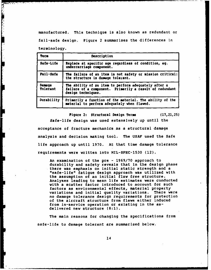
d. Provide a basis to improve structural criteria andmethods of design, evaluation, and substantiation forfuture aircraft designs.(12:3)
These ASIP activities are normally performed by the
contractor responsible for the structural design of the
aircraft. The four aims stated above translate into the
following sub-programs:
a. Environmental Stress Spectra Program. This program
periodically updates the stress spectra used for the design
to determine If it is representative of actual usage.
Differences found can be related back to particular critical
points and new life/damage assessments made.
b. Individual Aircraft Tracking (IAT). The individual
aircraft tracking program allows the determination of
cumulative fatigue damage for each aircraft.
c. Force Structural Maintenance Plan (FSMP). The FSMP
details the maintenance actions and modifications required
to ensure structural integrity throughout an airframes life.
Together these programs and elements provide detailed
information about the airframe, its previous usage and its
projected useful life. Depending on the aircraft type and
mission profiles there exist a number of techniques for
achieving the goals of ASIP. These are well documented in
References 4 and 7. The methods described fall into three
categories:
30
DM

a. Manual flight profile recording and damage translation
based on standardised mission profile/stress spectra.
b. "C" loading exceedance data and its translation to
critical point damage accumulation.
c. Direct measurement of critical point stress/strain
through use of strain or crack growth gauges.
Each of these categories are applicable to specific
aircraft types and their respective mission profiles.
Reference 4 provides guidance on each methods applicability.
Each of these methods require considerable resources to
implement, ranging from sophisticated aircraft mounted data
acquisition systems to extensive data processing computers.
Effectiveness of RCM/MSG Approaches
The RCM/MSG approach has been implemented in both
military and commercial operating environments. This begs
the question of just how effective are these methodologies
in achieving their aims.
... under traditional maintenance policies the initialprogram for the Douglas DC-8 included scheduledoverhaul for 339 items, whereas the initial program forthe DC-10, based on MSG-2, assigned only seven items tooverhaul. One of the items no longer subject to anoverhaul limit in the later program was the turbineengine. Elimination of this scheduled task not onlyled to major reductions in labor and materials costs,but also reduced the spares-engine inventory requiredto cover shop maintenance by more than 50 percent.Since engines for larger airplanes now cost upwards of$1 million each, this is a respectable saving (25:5).
31

The above shows that the positive effect that the MSG
approach had in the commercial area. However, in the
military implementations, there has been less success in
quantifying improvements bought about by RCM.
The first military implementation of RCM/MSG
methodology in the USA was on a squadron of P3's operated by
the USN. Initial estimates of saving through the improved
maintenance methodology a 50 percent reduction in scheduled
maintenance tasks, increased aircraft availability, reduced
manpower, and a lengthening of maintenance intervals (15).
This reported success caused a service wide adoption of the
RCM/MSG process with the hope of greater savings across all
armed services (2:17-19,27:27-34).
During budget testimony for financial year 1986 the US
services were asked to estimate cost savings due to the
implementation of RCM. None of the services were able to do
so. Lack of appropriate data was quoted as one of the main
reasons for not being able to quantify savings. The USAF
stated that "the point of RCM is increased availability of
weapons without a decrease in safety or reliability (28)."
Consequently, the effect of RCM/MSG on aircraft
maintenance is not as easily measurable in the military
environment as it is in the commercial.
32

Overview
So-far, the relationship between structural
characteristics and maintenance programs has been developed.
The historical development of structural maintenance program
philosophies has been discussed and the different methods
used by both military and commercial operators have been
presented. In particular, the reasons for differences
between commercial and military approaches has been
presented. The overall effectiveness of RCM/MSG programs
was also briefly discussed.
Current structural maintenance practices appear to
follow the MSG-3 approach with the military monitoring
fatigue on an individual aircraft basis. Chapter IV will
discuss whether the literature and actual practice coincide
and whether these methods and those used by the RAAF
coincide.
33

III. MethodoloQv
This chapter details the methodology used to answer the
research questions detailed in Chapter I.
General Methodoloav
This research effort is exploratory in nature. The
main purpose of the research is to identify current
philosophies or methodologies which may be beneficial for
the RAAF to pursue in updating its structural maintenance
philosophy and methodology. Aircraft maintenance
philosophies have tended to be evolutionary and have been
derived from commercial operator reactions to regulatory
pressures. Consequently, the primary sources of information
for this thesis are public domain reports and other
published information. Chapter II consists of a broad
summary of the major developments in maintenance philosophy
and structural methodologies since about 1965.
To determine current structural maintenance methods the
most current documents of maintenance policy need to be
referenced. These were already available through the
literature review effort and where applicable were applied.
Corroborating data was obtained through a series of
telephone interviews with maintenance program managers at
the organisations reviewed. In this way some added insight
into the issues as well as discussion on some of the
34

subjective aspects of structural maintenance could be
obtained.
The telephone interviews were casually structured so
that the interviewee would not feel defensive about their
organisations policies. The questions listed in Appendix A
were answered during the course of the inter-'iew.
SDecific MethodoloQv
Research Question 1.
What philosophies and method are used by commercialaircraft operators in the United States for managingscheduled maintenance for aircraft structures?
The purpose of this question is to ascertain the
current structural maintenance philosophy used by various
commercial airline companies. Both regulatory bodies and
the airlines will be approached. To answer this question
the following organisations were contacted:
1. Federal Aviation Administration (FAA). The FAA is the
regulating body for commercial airlines in the United
States. Each airline must have a maintenance program for
each aircraft type approved by the FAA's Maintenance Review
Board (MRB). Therefore, the FAA's maintenance requirements
are important because they specify the minimum levels of
maintenance which airlines are to perform.
2. Air Transport Association of America (ATA). ,e ATA
was responsible for convening the Maintenance Steering Group
(MSG) which produced MSG-1 through MSG-3. Through the MSG
35
process new philosophies are developed and refined. ATA is
most likely to know the types of maintenance policies being
practiced throughout the USA by various commercial airlines.
3. Trans World, Piedmont and Eastern Airlines were
contacted by telephone to determine current methods used by
the commercial sector.
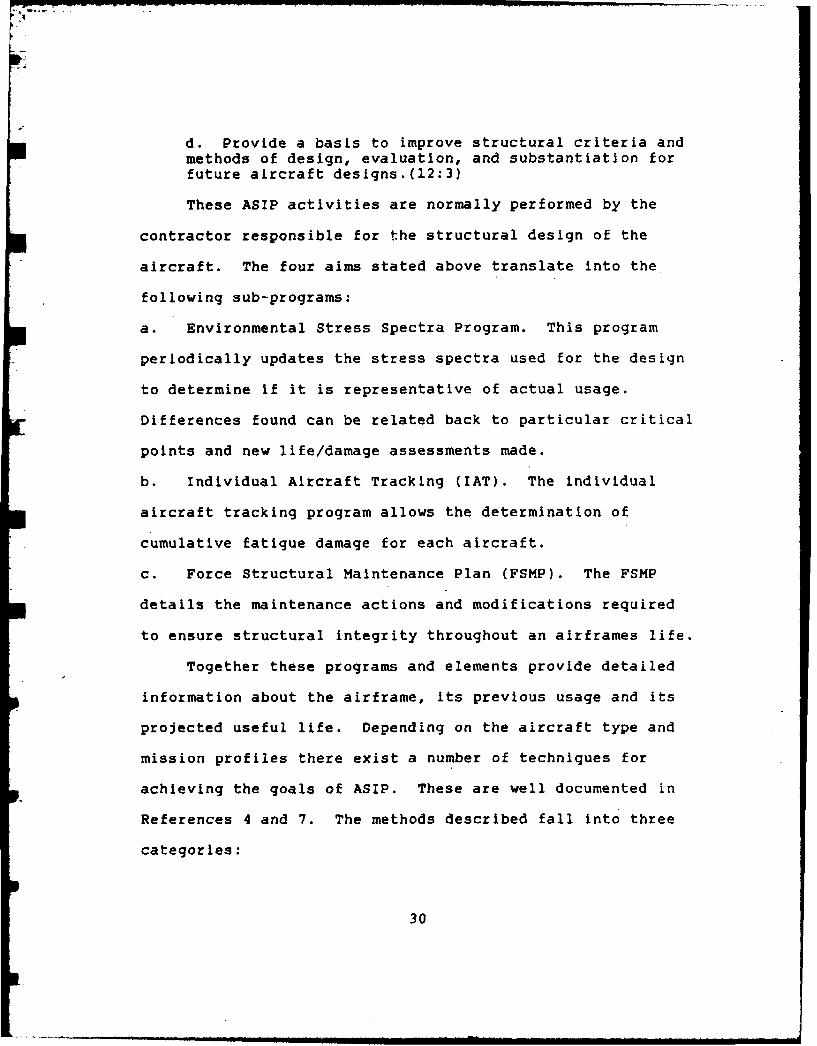
Research Question 2
What philosophies and methodologies are used bymilitary aircraft operators in the United States formanaging scheduled maintenance for aircraft structures?
The following military organizations will be researched
to obtain the necessary data:
1. Headquarters Air Force Logistics Command (HQAFLC)-
HQAFLC is the approving authority for all USAF maintenance
programs.
2. Naval Air Systems Command (NAVAIR) - NAVAIR was the
first military organization to implement a maintenance
philosophy based on the commercial airlines' MSG approach
and therefore have the most experience with its
implementation in a military environment.
Personal contact was possible with HQAFLC personnel,
particularly the ASIP program manager. The NAVY was
researched through the many available current reports.
Research Question 3
Are any of the methods identified above significantlydifferent to the method detailed in RAMP?
36

To answer this question required firstly, that the
maintenance philosophies in use in the USA be examined
against that used by the RAAF. To do this a published set
of philosophical aims were compared to the RAAF's stated
policy. Secondly, similarities and differences in the logic
diagram methodologies were determined. The methodology
currently used by military and commercial aircraft operators
(MSG-3) was used as a baseline for this comparison.
Research Question 4
Of the differences identified, are any significantenough to warrant inclusion in RAMP?
After identification of differences, their origin and
possible application to the RAAF environment will be
discussed. The discussion will be based on the concepts
presented in Chapter II. This.discussion will be a highly
subjective, but consistant with the research conducted.
37

IV, Findings. Comoarison and Discussion
Introduction
This chapter presents the data which was collected and
compares the different structural maintenance management
techniques used by American commercial and military
operators and the RAAF. This chapter, therefore, answers
research questions 3 and 4.
Findinqs
The discussion of scheduled structural maintenance
philosophies can be divided into three areas: Initial
Programs, Program Reviews, and Through-life Management
techniques. The discussion of the findings will follow this
same format.
Initial Programs. Figure 6 is a summary of the initial
program methodologies used by the organisations approached.
All operators have adopted the tenants of the MSG approach
in one of its forms. In the USAF this approach is known as
RCM, in the USN - AMP and in the RAAF, RAMP. The following
is a brief overview of each operators program. All the
commercial operators have been discussed at the same time
due to the similarity in their responses during interviews.
Commercial. Due to the regulatory process for
obtaining type certification for aircraft through the FAA in
the US, all commercial operators use the same approach for
38

Initial Program
Program Review
COMMERCIAL
TWA MSG MSGPiedmont MSG MSGEastern MSG MSG
MILITARY
USAF RCM (MSG-3) RCM (MSG-3)USH AMP (MSG-3) AMP (MSG-2)
RAAF RAMP (MSG-2) RAMP (MSG-2)
Figure 6: Methods for Determining orReviewing Maintenance Programs
determining scheduled maintenance requirements. Structural
programs are put together by working groups consisting of
manufacturer, operators and the FAA to determine an initial
maintenance program for the aircraft type. The FAA's
Maintenance Review Board then approves the initial program
and each operator submits a program tailored to its unique
operating environment or scenario. After the initial
requirements are determined each operators program may be
substantially different from all other operators of the same
aircraft type. See Figure 7 for details.
USAF. The USAF currently subscribe to the RCM
philosophy as given in MIL-STD-1873 which is based on MSG-3.
The RCM analysis brings together the structural information
generated by the ASIP/ENSIP programs and integrates it with
the past experience of the maintenance program managers.
39

00co o c
00
'. 0 0
0) it%. 0Og
> 'Da-0
4 0

Initial maintenance programs based on RCM are normally
generated by contractor. For large transport aircraft, the
procedures contractors use tend to follow commercialpractice
except that USAF programs, such as ASIP/ENSIP, tend to be
folded in. Consequently, USAF procedures do not differ
greatly from those given in MSG-3 (13,32).
USN. The USN's structural procedures are based on
MSG-3 and known within the Navy as the Analytical
Maintenance Program (27:30-34). These procedures are thus
very similar to those used by the commercial operators.
RAAF. The majority of aircraft purchased by the
RAAF are done so "off the shelf". Consequently, the RAAF
have little to no control over those design decisions which
affect the long term maintainability of the airframe. Not-
withstanding this however, the RAAF normally perform their
own maintenance engineering analysis (MEA), using available
manufacturer and operator data, to determine the initial
maintenance program for the structure.
This analysis is conducted in accordance with the RAMP
procedures specified in Reference 10. These procedures are
based on MSG-2 (1).
Maintenance Program Reviews. Maintenance program
reviews are conducted for many reasons, but primarily to
validate and update initial programs. Mechanisms which
trigger structural scheduled maintenance reviews include
41

structural modifications, premature failures, results of
inspection programs, or even changes in operations. In
addition, initial programs are normally reviewed at some
predetermined calendar interval. The following are some
details of each operators methods for conducting program
reviews.
Commercial. Changes to scheduled maintenance
programs In the commercial airline scenario has to be
approved by the FAA. Therefore, a logical and rigorous
procedure needs to be used. For this reason the Airlines
keep records on those components which they believe there is
benefit in reviewing scheduled maintenance actions.
Primarily, this benefit is economic.
Consequently, commercial airlines make extensive use of
the data packages already developed for the initial programs
and then they add to this data.with their own operational
experiences. The same logic processes present in the
Initial programs are generally followed to support any
recommended changes. The MSG-3 style of analysis is
commonly utilised when applicable.
USAF. Although the USAF uses contractors to
generate the initial structural-maintenance programs for new
aircraft, RCM (13) is used to evaluate new tasks and to re-
evaluate maintenance programs efficiency. Inputs used to
trigger a re-analysis come from the field, ASIP/ENSIP
42
programs or as a result of other non-routine investigations
(25,31).
USN. The USN use the methods detailed in the AMP
to review their maintenance programs. They use "a dedicated
age exploration technique and actuarial analyses (31:847)"
to Justify any changes to programs.
RAAF. The procedures in Reference 10 include a
logic diagram for determining the level of analysis required
to Justify changes to a maintenance program. This logic
diagram is reproduced in Appendix G. After the level of
analysis is determined the appropriate analysis is
undertaken.
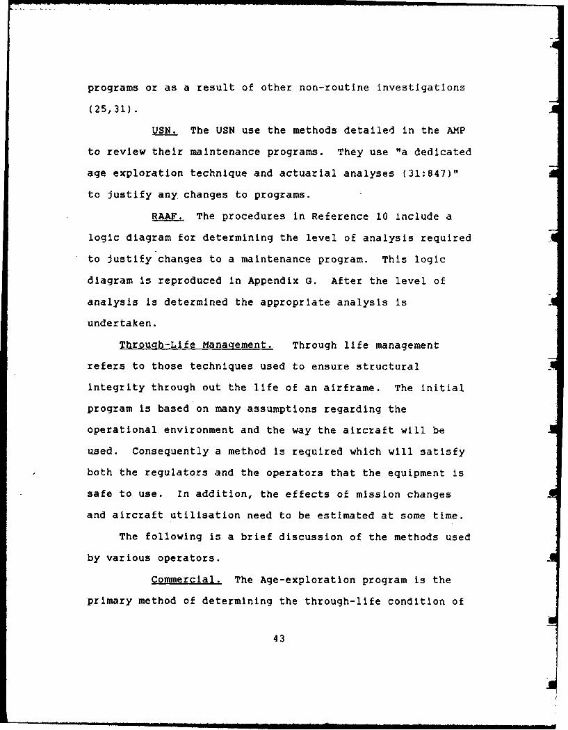
Through-Life Management. Through life management
refers to those techniques used to ensure structural
integrity through out the life of an airframe. The initial
program is based on many assumptions regarding the
operational environment and the way the aircraft will be
used. Consequently a method is required which will satisfy
both the regulators and the operators that the equipment is
safe to use. In addition, the effects of mission changes
and aircraft utilisation need to be estimated at some time.
The following is a brief discussion of the methods used
by various operators.
Commercial. The Age-exploration program is the
primary method of determining the through-life condition of
43

a fleet of aircraft. The assumption of average usage rates
and high time aircraft being representative of the fleet is
the under-pinning of the age exploration program.
Commercial operators sample the high time aircraft in their
own fleet or, in conjunction with other operators of the
same aircraft, in the whole fleet and use the results of
these sampled inspection programs to Justify interval
changes within the existing maintenance program (3,6,9,23).
USAF. Military operators are not as comfortable
with the notion of fleet-leader sampling as the commercial
operators are. Hence, the USAF expend a great deal of
resources tracking individual aircraft usage.
The USAF use many methods to track individual aircraft
fatigue damage accumulation Reference 4 describes each in
detail. In particular, different methods are employed
depending on the type of aircraft and its mission profile.
The following are the four main methods used
a. manual logs,
b. acceleration exceedance data,
c. stress/strain transfer function,
d. crack growth.
In addition to IAT, the USAF regularly performs
Environmental Stress Spectra surveys of a fleet to ensure
that the average spectrums that were applied during design
44

and are being applied in conjunction with the IAT programs
are valid.
USN. The USN's methods appear to be somewhere
between the methods used by the USAF and those used by
commercial operators. They subscribe heavily to the age-
exploration concept as well as recording usage parameters.
The USN's most recent acquisition, the F/A-18, is being
managed as follows:
The age exploration program will be based uponexamining statistically determined samples of aircraftstructure at designated cyclic thresholds (flighthours, catapults, arrestments, operatingcycles, calendar age, etc.) to determine materialcondition (31:849).
Each F/A-18 has strain gauges bonded to the structureat seven locations. The in-flight strain is recordedon an in-flight recorder whenever specified exceedancecriteria are met. Flight data such as airspeed, rollrate, altitude, and "G" load are concurrently recordedon the tape with the strain gauge information. Thesedata will be definitive and extremely valuable to thesustained structural age exploration program (31:850).
Through the analysis of data, the significant orcritical airframe elements requiring periodicinspection will be confirmed. Elements requiringredesign will be isolated, and recommendations tostructural service life limits will be made (31:850).
The above demonstrates the age-exploration program
being used by the USN on the F/A-18 as well as the use of
individual aircraft data to backup the program. The
aircraft data is not used to program specific maintenance
tasks or to determine the timing of modification programs
for individual aircraft.
45

RAAF. The RAAF also conducts individual aircraft
tracking programs on aircraft in its fleet. The following
methods are used:
a. Simple hours based life.b. Safe life and fatigue meter data.c. Durability and Damage Tolerance Assessment(DADTA)incorporating safety-by-inspection and fail-safephilosophy based on crack growth modelling.d. Strain range recording using the Aircraft FatigueData Analysis System (AFDAS).e. Mission profile recording (16:2).
These methods are very similar to the methods outlined
in Reference 4.
Comparison
The purpose of this section is to compare the
structural maintenance philosophies and methods currently in
use in the US against those used by the RAAF. Previously,
as shown in Figure 6, it was shown that all US operators
base their initial program and program review procedures on
the philosophy and methods described in MSG-3.
Consequently, the task of comparing the RAAF with US
operators becomes one of comparing the RAAF Analytical
Maintenance Plan to MSG-3.
The success of any comparison usually lies in the
establishment of a base line from which to make comparisons.
MSG-3 is a detailed methodology for determining aircraft
maintenance requirements. It includes a methodology for
determining structural maintenance requirements. However,
46

nowhere in any of the MSG documents is the maintenance
philosophy or precepts described. Consequently, since
Nowlan and Heap (25) are the only source of a clear
description of the precepts of modern maintenance programs,
the precepts presented in their report will be used as the
philosophical baseline for comparison. These precepts are
consistent with the methodologies expressed in the MSG
series documents.
The MSG-3 document will be used as a methodology baseline
as it represents the latest in the MSG evolutionary cycle.
Philosophy. The major precepts described by Nowlan and
Heap are reproduced in Appendix B. The maintenance concepts
upon which the RAAF base their maintenance programs on is
contained in Reference 11. Each major RCM precept was
examined to determine whether the same or an equivalent
concept was contained in RAMP. The result of this analysis
is contained in Appendix C and supports the contention that
the major precepts of RCM can be found In RAMP.
MSG-3 Methodology. The structural maintenance
methodology used by MSG-3 is presented in Appendix D. This
was used as a basis for comparison of RAMP structural
maintenance methodology.
Attached at Appendix F is the structural logic diagram
used in MSG-3. Appendix G contains a logic diagram RAMP
uses to determine the level of analysis required for
47

structural items whilst Appendix H contains the logic
diagram used to determine maintenance requirements. A
cursory look at these diagrams reveals substantial
differences in content and logic flow.
The results of the comparison are presented in Appendix
E and basically show little similarity between the
procedures used in MSG-3 and RAMP.
Discussion
The RAMP flow-chart is loosely based on MSG-2 procedures
(1). MSG-3 was not a significant departure from the basic
method supported by MSG-2 as the philosophy review
indicates. However, as noted in Chapter II there are some
significant differences in structural maintenance
methodology. In particular the following differences are
significant with respect to aircraft structures:
a. MSG-3 takes a consequence of failure approach.
b. Task orientated program development, (MSG-2 was
maintenance process oriented).
c. Recognises damage tolerance rules of FAR 25.571.
d. Definite applicability and effectiveness criteria has
been developed to provide a more rigorous selection of
tasks.
e. Structures logic directly assess the possibility of
structural deterioration process. "Considerations of
fatigue, corrosion, accidental damage, age exploration and
48

others, are incorporated into the logic diagram and are
routinely considered (21:iii)."
f. Multiple failures are considered in structural
evaluation.
g. The responsibility for determining rating schemes for
the structural damage process now rests with the program
review team (21:ii-iii).
Reference 29 contains a discussion on whether the RAAF
Maintenance Engineering Analysis (MEA) should amend its
flow/logic diagrams to MSG-3 format. The conclusions
reached at that time were as follows:
a. Both MSG-3 and MEA result in task orientated
maintenance programmes derived from.similar analysis logic.
b. MSG-3 is designed specifically for new transport
aircraft.
c. MSG-3 is expensive in terms of man-power and data
requirements, especially for structural analysis; this task
could only be undertaken by the airframe manufacturer.
d. The clearer logic paths could be introduced into RAAF
MEA, but only after analysis by a dedicated team when
sufficient data on the practical results of MSG-3 is
available.
e. MSG-3 is expected to have a minimal impact on the
scheduled maintenance of specifically designed military
aircraft. (29:1).
49

Careful examination of the MSG-3 document and Reference
10 supports the contention that both result in
effective/efficient tasks. Maintenance programs are by
necessity task orientated. To specify a maintenance process
as part of a maintenance program is not practical. The MSG-
3 logic diagram recognises this and evaluates maintenance
actions from a task viewpoint rather than the process
viewpoint. This subtle difference between the MSG-2 and 3
approaches, does not impact the final maintenance program.
It is quite likely that a maintenance evaluation team would
arrive at a similar maintenance program under both schemes,
however the clearer logic paths of MSG-3 would help
maintenance program developers as well as providing the
consistent basis for further reviews.
Figure 7 showed the major steps required to determine
an initial structural maintenance program. The operator
(RAAF) is primarily responsible for determining task
efficiency and has an input into task selection and
effectiveness. Consequently, with respect to initial
program development, a decision diagram which will aid in
the selection of tasks which are both effective and
efficient would be useful. This requires that the decision
process/methodology considers all likely deterioration
processes and potentially effective tasks.
50

To determine the effect of structural deterioration
processes on aircraft structures, a rating scheme is
normally used. The rating scheme is devised by the review
team which normally comprises manufacturer and operator
representatives and considers the three deterioration modes
experienced by structures. Figure 8 describes the key
considerations for accidental damage rating (ADR) and
environmental damage rating (9DR) of aircraft structures.
Ratings for structures is considered the domain of the
manufacturer. In the past the RAAF have had access to the
rating schemes devised by other operator/manufacturer review
teams. This is not expected to change in the future,
particularly for aircraft made in the USA.
Consequently, the use of a logic diagram similar to
that in MSG-3 would be consistent with RAAF requirements.
Additional Issues. During the course of this research
two issues surfaced which were not part of the research
requirement but never-the-less warrant a brief mention. The
two issues were:
a. The integration of fatigue data and RCM/MSG
methodologies.
b. Further improvements to the MSG process.
51

Primary KeyApplication Responsibility Consideration
RatingCategory EDR ADR OPERATOR MAKER
Visibility forVisibility # # # inspection after access.
Sensitivity to Relative sensitivitydamage size within zone considered.or growth # # # External : Multiple
element damage.Internal : Singleelement damage.
Environmental Comparison with previousProtection # # protection system
recent service history.
Exposure to # Corrosion experienceadverse in same zone.environment ,,
Material susceptibility# to stress corrosion and
potential for preload.
Likelihood of Operator experience inaccidental # # same zone.damage
Strength after Likely size of damageaccidental # # relative to criticaldamage. damage size.
Figure 8: Key Considerations and Responsibilitiesfor EDR and ADR Evaluation (17: Figure 12)
Integration of Fatigue Information. Discussions with
members of the USAF involved with RCM (32) and ASIP (24)
revealed a cultural gap in the integration of the
information from both programs into an overall structural
52

maintenance program. From the reading of the ASIP and Force
Management literature (4,7,8,14) it is easy to get the
impression that the USAF are only concerned with fatigue
damage and individual aircraft tracking programs. The
intention of RCM is to incorporate the inspection
requirements of the ASIP/ENSIP programs with the entire
scheduled maintenance requirements for the aircraft. In
particular, the specific inspection requirements need to be
folded into the overall inspection requirements to ensure
the most efficient packaging of scheduled tasks.
Discussions with ASIP staff (24) revealed two
objections to the RCM approach. These were as follows:
a. The use of rating schemes for environmental and
accidental damage to change fatigue inspection intervals.'
b. The possibility of damage being introduced by requiring
too frequent inspections of areas which require the
disassembly of other areas of structure.
The use of rating schemes has been widespread in
commercial applications since the MSG/RCM methodology
recognised that structures required a unique way of handling
its requirements. These rating schemes acknowledge the
randomness of some damage mechanism which would not normally
be considered. In addition they allow the operator to fold
his experience into the program through changes to
inspection frequencies on known problem areas. Since
53
corrosion, in particular, can have an adverse effect on the
fatigue characteristics of the structural details,
sufficient inspections must be catered for. Corrosion
inspections are normally done via the zonal inspection
system, RCM/MSG is the best method available for ensuring
that fatigue critical areas are adequately inspected.
The actual maintenance program is determined by
structural specialists who are aware of the ramifications of
inspections which require dismantling of other structure to
achieve the inspection. Good education programs would help
alleviate any fears of poor maintenance practice being put
into a program.
The key to structural maintenance efficiency is having
the fatigue program fully integrated with the structural and
other maintenance requirements.
To a limited extent this same cultural gap is present
in the commercial arena (6).
MSG-4? At the time of this research effort a
revision to MSG-3 is before the FAA for approval. With
respect to structures it was determined that the major
change would be that the structural methodology would
reflect the practice of rating SSI's for environmental and
accidental damage prior to folding in the fatigue
requirements (6).
54

Reference 5 identified a number of other areas of the
MSC-3 process which could be improved from a manufacturers
perspective. The 13 recommended changes include rewording
the logic questions to reflect maintenance goals,
simplifying the logic diagrams and improving the Maintenance
Significant Item (MSI) selection process.
55
V. Conclusions and Recommendations
Conclusions
The RAAF's maintenance philosophy, detailed In
Reference 11, is consistent with current maintenance
philosophies being used in the United States of America
(USA) by both commercial and military operators. The
methodology for determining scheduled structural maintenance
requirements is not current with methods being used in the
USA.
Previously, RAAF assessments of the MSG-3 maintenance
methodology concluded that a wait and see attitude should be
taken. There is now sufficient evidence the success of the
MSG-3 approach, by both commercial and military operators to
support the adoption of its methodology. Consequently, the
structural methodology outlined in MSG-3 (21) and repeated
in Appendixes D and F should be adopted by the RAAF for all
new aircraft of American origin.
Recommendations
The following actions are recommended:
a. RAMP (10) be amended to include the structural
maintenance methodology outlined in Appendix D.
b. RAMP be amended to include the structural maintenance
logic diagram outlined in Appendix F.
56

Recommendations for Further Study
The following areas of further study are recommended:
a. Apply the MSG-3 methodology to a RAAF aircraft
structure which has already been assessed under a MSG-2
approach.
b. Review current methods used to determine initial
inspection intervals for aircraft structures. Determine the
statistical validity of sampling schemes and full scale
tests.
c. Examine whether the MSG-4 (the soon to be released MSG-
3 revision) would be worth adopting by the RAAF.
d. A cost benefit analysis of Individual Aircraft Tracking
programs be undertaken to determine if they are worthwhile.
e. An investigation of ways of measuring maintenance
performance in a not for profit organisation.
f. An analysis of the statistical significance of the
results of fatigue tests done on only one airframe. In
particular, determine the validity of maintennace programs
based on these test results.
57

Agpendix A
Telephone Interview Framework
1. Were any of these subjected to MSG maintenance program
evaluation techniques.
Discuss those that were, or why they weren't.
2. Do you use the MSG process to determine maintenanceprogram changes.
Discuss.
3. Do you partake in age-exploration of structural items.
4. Do you track fatigue information on an individualaircraft basis.
Discuss any methods used to track usage parameters.Discuss what is done with the information.
5. Do you record environmental stress spectra to validatethe design spectra applied.
6. Do you use any method of usage averaging. i.e do allaircraft operate on exactly the same routes, are theyrotated or dedicated to particular routes.
7. Do you have any incentive to remove tasks from themaintenance program.
8. On what basis are aircraft selected for structuralmaintenance;age (flight cycles or hours) or accumulateddamage?
58

Appendix B
RCM - A MAINTENANCE PHILOSOPHY
An operator's maintenance program has four objectives:
1. To ensure realization of the inherent safety and
reliability levels of the equipment.
2. To restore safety and reliability to their inherent
levels when deterioration has occurred.
3. To obtain the information necessary for design
improvement of those items whose inherent reliability proves
inadequate.
4. To accomplish these goals at a minimum total cost,
including maintenance costs and the costs of residual
failures.
Reliability-centered maintenance is based on the following
precepts:
1. A failure is an unsatisfactory condition. There are two
types of failures: functional failures, usually reported by
operating crews, and potential failures, usually discovered
by maintenance crews.
2. The consequences of a functional failure determine the
priority of maintenance effort. These consequences fall
into three categories:
59
" " m.auN mma ml llmm m m m.... .. .

a. Safety consequences, involving possible loss of the
equipment and its occupants.
b. Operational consequences, which involve an indirect
economic loss as well as the direct cost of repair.
c. Non-operational consequences, which involve exposure to
a possible multiple failure as a result of the undetected
failure of a hidden function.
3. Scheduled maintenance is required for any item whose
loss of function or mode of failure could have safety
consequences. If preventive tasks cannot reduce the risk of
such failures to an acceptable level, the item must be
redesigned to alter its failure consequences.
4. Scheduled maintenance is required for any item whose
functional failure will not be evident to the operating
crew, and therefore reported for corrective action.
5. In all other cases the consequences of failure are
economic, and maintenance tasks directed at preventing such
failures must be Justified on economic grounds.
6. All failure consequences, including economic
consequences, are established by the design characteristics
of the equipment and can be altered only by basic changes in
the design:
a. Safety consequences can in nearly all cases be reduced
to economic consequences by the use of redundance.
60

b. Hidden functions can usually be made evident by
instrumentation or other design features.
c. The feasibility and cost effectiveness of scheduled
maintenance depend on the inspectability of the item, and
the cost of corrective maintenance depends on its failure
modes and inherent reliability.
7. The inherent reliability of the equipment is the level
of reliability achieved with an effective maintenance
program. This level is established by the design of each
item and the manufacturing processes that produced it.
Scheduled maintenance can ensure that the inherent
reliability of each item is achieved, but no form of
maintenance can yield a level of reliability beyond that
inherent in the design.
A reliability-centered maintenance program includes only
those tasks which satisfy the criteria for both
applicability and effectiveness. The applicability of a
task is determined by the characteristics of the item, and
its effectiveness is defined in terms of the consequences
the task is designed to prevent.
8. There are four basic types of tasks that mechanics can
perform, each of which is applicable under a unique set of
conditions. The first three tasks are directed at
preventing functional failures of the items to which they
61

are assigned and the fourth is directed at preventing a
multiple failure involving that item:
a. On-condition inspections of an item to find and correct
any potential failures.
b. Rework (overhaul) of an item at or before some specified
age limit.
c. Discard of an item (or one of its parts) at of before
some specified life limit.
d. Failure-finding inspections of a hidden-function item to
find and correct functional failures that have already
occurred but were not evident to the operating crew.
9. A simple item, one that is subject to only one or a very
few failure modes, frequently shows a decrease in
reliability with increasing operating age. An age limit may
be useful in reducing the overall failure rate of such
items, and safe-life limits imposed on a single part play a
crucial role in controlling critical failures.
10. A complex item, one whose functional failure may result
from many different failure modes, shows little of no
decrease in overall reliability with-increasing age unless
there is a dominant failure mode. Age limits imposed on
complex components and systems (including the equipment
itself) therefore have little of no effect on their overall
failure rates.
62

The RCM decision diagram provides a logical tool for
determining which scheduled tasks are either necessary or
desirable to protect the safety and operation capability of
the equipment.
11. The resulting set of RCM tasks is based on the
following considerations:
a. The consequences of each type of functional failure.
b. The visibility of a functional failure to the operating
crew (evidence that a failure has occurred).
c. The visibility of reduced resistance to failure
(evidence that a failure is imminent).
d. The age-reliability characteristics of each item
e. The economic tradeoff between the cost of scheduled
maintenance and the benefits to be derived from it.
12. A multiple failure, resulting from a sequence of
independent failures, may have consequences that would not
be caused by any one of the individual failures alone.
These consequences are taken into account in the definition
of the failure consequences for the first failure.
13. A default strategy governs decision making in the
absence of full information or agreement. This strategy
provides for conservative initial decisions, to be revised
on the basis of information derived from operating
experience.
63

I
A scheduled-maintenance program must be dynamic. Any prior-
to-service program is based on limited information, and the
operating organization must be prepared to collect and
respond to real data throughout the operating life of the
equipment.
14. Management of the ongoing maintenance program requires
an organized information system for surveillance and
analysis of the performance of each item under actual
operating conditions. This information is needed for two
purposes:
a. To determine the refinements and modifications to be
made in the initial maintenance program (including the
adjustment of task intervals)
b. To determine the needs for product improvement.
15. The information derived from operation experience has
the following hierarchy of importance:
a. Failures that could affect operating safety.
b. Failures that have operational consequences.
c. The failure modes of units removed as a result of
failures.
d. The general condition of unfailed parts in units that
have failed.
e. The general condition of serviceable units inspected as
samples.
64

16. At the time an initial program is developed information
is available to determine the tasks necessary to protect
safety and operating capability. However the information
required to determine optimum task intervals and the
applicability of age limits can be obtained only from age
exploration after the equipment enters service.
17. With any new equipment there is always the possibility
of unanticipated failure modes. The first occurrence of any
serious unanticipated failure immediately sets in motion the
following product-improvement cycle:
a. An on-condition tasks is developed to prevent
recurrences while the item is being redesigned.
b. The operating fleet is modified to incorporated the
redesigned part.
c. After the modification has proved successful, the
special task is eliminated from the maintenance program.
18. Product improvement, based on identification of the
actual reliability characteristics of each item through age
exploration, is part of the normal development cycle of all
complex equipment.
65

Appendix C
Results of Comparison BetweenMaintenance Philosophies
RCM Objective RAMP (AAP 7001.038-1) CommentsParagraph reference
1 106,115 Supported
2 104 Supported
3 Supported through data collection.
4 115,116 Supported
RCM Precept
- 1 445 Supported
2a. 427-431 Supportedb. 432-434 Supportedc. 435 Supportedd. 441-444 Supported
3 430 Supported
4 444 Supported
5 435 Supported
6 130 Supporteda. 439 Supportedb. These two items represent modificationsc. which would become evident later or be
fixed during production
7 129-130 Supported
8 227 Supporteda. 219 Supportedb. 230-233 Supportedc. 240 Supportedd. 241-245 Supported
9 408-409,421 Supported
10 409-410 Supported
66
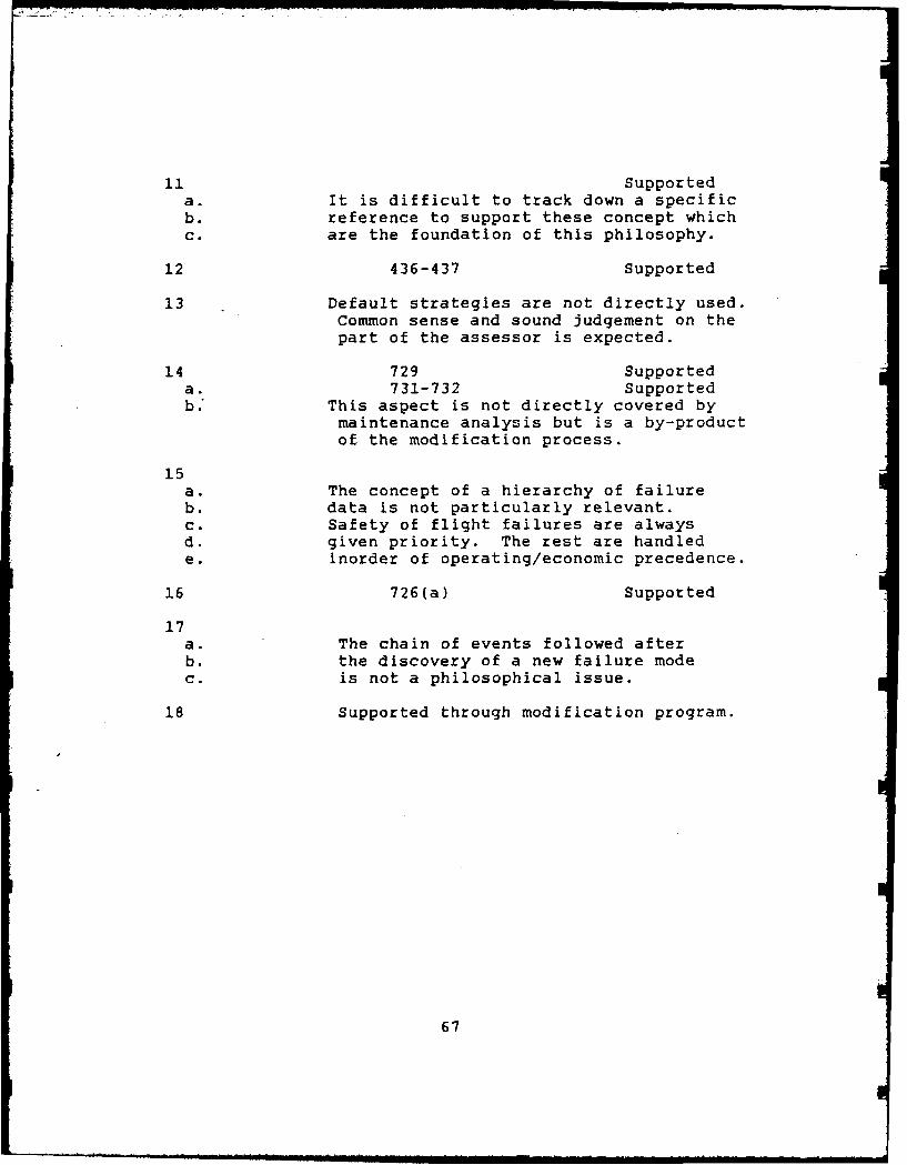
11 Supported
a. It is difficult to track down a specificb. reference to support these concept whichc. are the foundation of this philosophy.
12 436-437 Supported
13 Default strategies are not directly used.Common sense and sound judgement on thepart of the assessor is expected.
14 729 Supporteda. 731-732 Supportedb.' This aspect is not directly covered by
maintenance analysis but is a by-productof the modification process.
15a. The concept of a hierarchy of failureb. data is not particularly relevant.c. Safety of flight failures are alwaysd. given priority. The rest are handlede. inorder of operating/economic precedence.
16 726(a) Supported
17a. The chain of events followed afterb. the discovery of a new failure modec. is not a philosophical issue.
18 Supported through modification program.
67

Appendix D
MSG-3 Structural Methodology
The method for conducting structural item analysis as
given in MSG-3 is as follows:
1. Identify items as Structurally Significant Items (SSI)
or Other Structure.
2. Classify SSI's as damage tolerant or safe-life
structure.
3. For each damage tolerant SSI, rate separately its
susceptibility to each of the three deterioration processes:
a. Fatigue.
b. Environmental deterioration.
c. Accidental Damage.
4. Select for each damage tolerant SSI the following
inspection features:
a. Level and method of inspection.
b. Inspection threshold.
c. Frequency of inspection (repeat interval).
d. Fleet leader/age exploration program, if applicable.
5. For each safe-life SSI, rate separately its
susceptibility to the two deterioration processes:
a. Environmental.
b. Accidental Damage.
68

6. Select for each safe-life SSI the following inspection
features:
a. Level and method of inspection.
b. Threshold of initial inspection (if appropriate).
c. Frequency of inspection (repeat interval).
7. Ovc Iy the inspectfon requirements for each SSI
according to the deterioration processes for which it was
rated. Consolidate tasks and document the results.
8. For Other Structure, establish appropriate maintenance
tasks based on:
a. Past experience,and/or,
b. Manufacturer's recommendation for new materials and/or
concepts.
69

L
Appendix E
Results of Comparison Between
Structural Maintenance Methodologies
MSG-3 Method RAMP Comments
1 NoClassified as Primary
2 No or secondary.
3 No Rating schemesnot used.
4 No Inspection thresholdsnormally given.
Fleet Leader/Age Explorationnot formally done.
5 No Rating schemes not used.
6 No Rating schemes not used.
7 Yes All tasks arising from analysisare consolidated into one program.
8 Yes All structure subject to zonalrequirements.
Note. Refer to numbering in Appendix D.
70

A02endix FMSG-3 Structural Logic Diagram
0
up.- (II)c 0
zI Iii Iu IIIei0 -- j 0r0
cc u 0 c C 4 0 gowZw 5 0 - t
Cw -CWC * Z 4
0M < zlz~c Z -0
!Zocc_____C __ ovu x ZIz . j
Z co
cc Ul z 71

-j LL L.
wW WI 0 UjLL .ZZO
0- <wiw
Loo
0z
w
Z
e0,
0T
Cow ()wI...JOW z CCC W
U) w(OOWJ<-<LL0
z- ( ) 2 - z CWO<W OzW-C-D S-0
LU Z « C w(-i r g<:: c.-wzM
N C
72
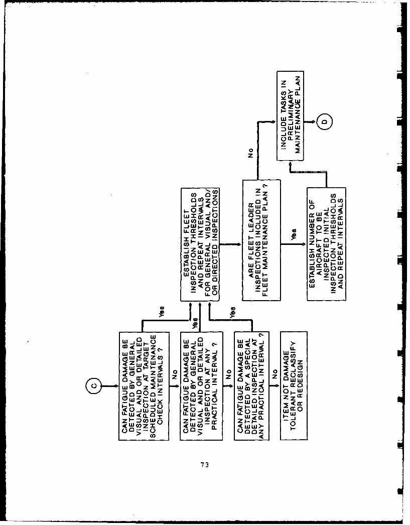
zz
JZ
_jcr
0 CL
z
C,) ) C,
LL. ao U)
-j_ WOZ
0 9- w
-JOZWC QWcLOO
00 Wcr w
LW
)w z
w i w <'.
ca0C :_ 0 j W cc Q0
ILWa-0 W W84CCJ)raWfJ
WWOn-0 < 0. 0OO~-O 6- z-
co) O00z0
CC73 w c

w~ z4u(z WI- - -J wcozI1-W z M
:. <0z <ZO
00 0o
z 5z-wC _ rF
I-mo 90 a aW ~ - 0Z cccrQw
zi~ ozT-ZOO
-ZI WI- 0z u 0zY~i 0O g w-->- ) -~-
Z0<! 0 0
z z
zoZ MI co0X -occ~. W0 __j X W
W I0- >W-,60 r-ZW W-'J
Z ~ C W Oaw c 4 r
W a : Ix W 74

OW
lU. x rLL W -j
cc LL a LL I-- zL Z ) C
-<1 c<rm 6<W
(WWZ < - z z
0W p wO< !
z 0U, ~ ~ Ww<x:)z :W
< 0 (J i <
0< lit] 0(o 3 (0LE
0o co.-.c0
zz
T WW
0<1- 0 1- z0
Y. Zw
0c W- CI'WZ5 wO.W5
0z -0 0 cc
<75

Appendix G
Level of Analysis Diagram
IDENTIFY TASKSPERFORMED ONEACH ITEM/AREA
IS THE TASK NO IS GENERALYES PREVENTIVE or SPECIFIC SURVEILLANCE
SURVEILLANCE JUSTIFED
IDENTIFY ORIGINOF TASK7I
PRESCRIBED BYSTATUTORY ... --NO or -NO
AUTHORITY UNK5WN
C SI. N
411
ASSEMLE RELE'VANT 1IN-SERVICEIDATA FOR REVIETW DEFECTBY AIRENG5(DEFAIR)
INCLSIO IN NEW 0ANCE
P__ROGRAM & I (A&A ) I
I ~ABBREVIATED;ES EVALUATION
I PROCEDURE
-~ EVAEUATE TASK' . , | FORM 13 •
RETAIRETAIN /RSCILLREQUEREIREMENO
INCORPORATE IN
RETAn /RECORD) NEAC
LREQIREMENT
/, OMIT T'ASK
76

RAAM Decision Logic
C3 C)
a 00, r :czz
Z o
W~~
07

o0 zz0 w0 CD z w (1)c <
LU z p mw0 z 4" (0 < a:
> x X0 cc
-CCw to c w LU > (j) W
W - (1) 1 m
w - a w x W W
G - LL z U) z w !i - z
LL. w z z <Lij Qo cc z
: () 0 LU -LJL T 5 CD CC a:
w w c 0L I toz
X r C) E4) 43
z Cl)
wz _j
w 0 LU
Cc M
w Q)0
cc cr.w CL
w>
: y() ow j< w w 0U- z w C.) LU ZLL z 0 0)w 0 : z o C-roil o EZW
w P i-uj 0 z z womz a Q 0 Lu w -- 5
0 LL) < CL Z (3z LL Wx D LL C) uj
Q L:--<j
u LL ILLJ 0
Co (.)
cc
0
zT
78

cr
>00LLUJ LL
LLW cc 5~
WOW
0~I (a :)
1Wa: <: W<LZJW0
0. 0
< co 0
00
zz
79 M-

w W
0a0
0DL-
0000 z
c1-
0 0
08

Bibliography
1. Ahearn, Sqn Ldr D. Sponsorship of AFIT Thesis Topics,Minute on file AF 517/29/39 (68) Russle OfficesCanberra, 13 March 1987.
2. A'Hearn, Maj Francis W. The MSG2 Commercial AirlineConcept. A Department of Defense Program forReliability-Centered Maintenance. Study Project ReportPMC. Defense Systems Management College,Fort Belvoir VA, November 1977 (AD-A050531).
3. Andrews, George D.S. President. Telephone Interview.Transport Systems Consulting Corporation,Washington DC, 1 July 1988.
4. Berens, A.P. et al. Handbook Of Force ManagementMethods. Contract F33615-77-C-3122. Dayton OH.University of Dayton Research Institute, April 1981(AD-AII6974).
5. Bradbury, Scott J. "MSG-3 as Viewed by theManufacturer (Was it Effective?)," Aerospace Congressand Exhibition. Report 841482. Warrendale PA: Societyof Automotive Engineers, 1984.
6. Broyard, Micheal C. Chief Structural Engineer.Telephone Interview. Eastern Airlines, Miami FL,22 July 1988.
7. Clay, L.E. et al. Force Lanagement Methods Task IReport - Current Methods. Contract F33615-77-C-3122.Dayton OH. University of Dayton Research Institute,December 1978 (AD-A066593).
8. Coffin, M.D. and C.F. Tiffany. "New Air ForceRequirements for Structural Safety, Durability and LifeManagement," AIAA/ASME/SAE 16th. Structures.Structural Dynamics, and Materials Conference. AIAAPaper 75-781. New York: American Institute ofAeronautics and Astronautics, May 1975.
9. Davis, Stanley. Director of Maintenance Budgets andResources. Telephone Interview. Piedmont Airlines,Winston-Salem NC, 1 July 1988.
81

10. Defence Instruction (Air Force). Procedures for theDeterminating Aircraft Scheduled MaintenanceRequirements. DI(AF) AAP 7001.038-2. Melbourne: AIRENG3, 24 February 1984.
11. Defence Instruction (Air Force). RAAF AircraftMaintenance Philosophy and Policy (Third Edition).DI(AF) AAP 7001.038-1. Canberra: DMP-AF,1 September 1983.
12. Department of the Air Force. Aircraft StructuralIntegrity Program Airplane Requirements. MIL-STD-1530(11). Washington DC: 1 December 1972.
13. Department of the Air Force. Reliability CentredMaintenance for Aircraft, Engines and Equipment. MIL-STD-1843(USAF). Washington DC: 8 Feburary 1985.
14. Elliot, W.R. and T.F. Christian, Jr. "Methodology toBetter Predict Structural Maintenance Requirements forIndividual Aircraft," Aircraft Design Systems andOperations Research, AIAA-84-2411. New York: AmericanInstitute of Aeronautics and Astronautics, 1984.
15. Faulders, Cyril T. "The Analytical Maintenance Program- No More Maintenance as Usual," Defense ManagementJournal 13: 15-21 (July 1977).
16. Grey, Flt Lt Bradley A. Structural Integrity andThrough Life Monitoring of RAAF Aircraft, Minute,Russel Offices Canberra, 13 March 1897.
17. Hall, J. and U.G. Goranson. "Principles in achievingDamage Tolerance with Flexible Maintenance Programs forNew and Aging Aircraft," Proceedings of the 13th andAIAA Aircraft Systems and Technology Conference. 1393-1405. New York: American Institute of Aeronautics and
=Astronautics, 1982.
18. Harris, Kenneth D. Integration of RCM Analysis intothe S-3A Maintenance Program. MS THesis. Naval PostGraduate School, Monterey CA, December 1986(AD-A177421).
19. Maintenance Steering Group - 1 Task Force.Airline/Manufacture Maintenance Program PlanningDocument. MSG-l. Washington DC: Air TransportAssociation of America, 10 July 1968.
82

20. Maintenance Steering Group - 2 Task Force.Airline/Manufacture Maintenance Program PlanningDocument. MSG-2. Washington DC: Air TransportAssociation of America, 25 March 1970.
21. Maintenance Steering Group - 3 Task Force.Airline/Manufacture Maintenance Program PlanningDocument. MSG-3. Washington DC: Air TransportAssociation of America, October 1980.
22. Murnane, S.R. et al. "Northrop/United States Air ForceApplication of Failure Predictions to an OperationalAircraft," Proceedings of the Tenth Sysposium on NavalStructural Mechanics. 17-34. Washington DC: FractureMechanics, 1978.
23. Nakata, Dave. Manager, Reliability Control.(Mr. Nakata was formally at Trans World Airlines).Telephone Interview. North West Airlines,Minneapolis MN, 29 July 1988.
24. Nasal, Bernard. ASIP Program Director. Personal andTelephone Interviews. Headquarters AFALC, Dayton OH,March-July 1988.
25. Nowlan, F. Stanley and Howard F. Heap. ReliabilityCentered Maintenance. Washington DC: Office of theSecretary of Defense (Manpower, Reserve Affairs andLogistics), 29 December 1978.
26. Pontecorvo, Joseph A. "MSG-3 - A Method For MaintenanceProgram Planning," Aerospace Congress and Exhibition.Report 841485. Warrendale PA: Society of AutomotiveEngineers, 1984.
27. Rose, Charles V. The Development of ScheduledMaintenance Programs for Naval Aircraft. MS thesis,Naval Post Graduate School, Monterey CA, June 1984(AD-A051186).
28. "Savings are Uncertain, But DoD, Services Back RCM,"Aerospace Daily, 134:17, 133 (July 15, 1985).
29. Stokes, Flt Lt B.J. Maintenance Engineering Analysis -
Logic and Flow Charts. Minute 2616/17/TECH (11),20 June 1983.
83

30. Tipton, R. et al. Reliability Centered MaintenanceStudy - Final Report. July 1977 - August 1978.Contract DAAG 39-77-C-0169. Martin MariettaCorporation, Orlando Division.
31. Williams, Rear Admiral Allen D. "Age Exploration inNaval Aviation," Proceedings of the 13th and AIAAAircraft Systems and Technology Conference. 844-850.New York: American Institute of Aeronautics andAstronautics, 1982.
32. Wizimirski, Capt Ronald. RCM Lecturer. PersonalInterview. Air Force Institute of Technology,Dayton OH, January - July 1988.
84

Vita
Flight Lieutenant George W. Breen was born on
He completed high
school at Inala State High School in 1977. In January 1978
he Joined the RAAF as an Engineering Cadet and attended the
Royal Melbourne Institute of Technology. In December of
1981 he completed the requirements of a Bachelors Degree in
Mechanical Engineering and was subsequently given a
Commission in the RAAF as an Engineering Officer. FLTLT
Breen served as Officer in Charge of Ground Equipment
Maintenance Section, Number 35 Squadron Townsville and as a
Aerial Delivery Equipment Systems Engineer before entering
the School of Systems and Logistics, Air Force Institute of
Technology, in June 1987.
85

40 ASIFICAION OF THIS PAGE
Form ApprovedREPORT DOCUMENTATION PAGE OMBNo. 0704-0188
I&. REPORT SECURITY CLASSIFICATION lb. RESTRICTIVE MARKINGS
U4 CTAS s T __ En2&. SECURITY CLASSIFICATION AUTHORITY 3. DISTRIBUTION IAVAILABILITY OF REPORT
2b. DECLASSIFICATION / DOWNGRADING SCHEDULE Approved for public release;distribution unli imit ed
4. PERFORMING ORGANIZATION REPORT NUMBER(S) S. MONITORING ORGANIZATION REPORT NUMBER(S)
AFIT/GLM/LSM/88S-56a. NAME OF PERFORMING ORGANIZATION 6b. OFFICE SYMBOL 7a. NAME OF MONITORING ORGANIZATION
School of Systems (If applicable)
and Logistics I AFIT/LSM6c. ADDRESS (City, State, and ZIP Code) 7b. ADDRESS (City, State, and ZIP Code)
Air Force Institute of TechnologyWright-Patterson AFB OH 45433-6583
8a. NAME OF FUNDING/SPONSORING 8b. OFFICE SYMBOL 9. PROCUREMENT INSTRUMENT IDENTIFICATION NUMBERORGANIZATION (If applicable)
Bc. ADDRESS (City, State, and ZIP Code) 10. SOURCE OF FUNDING NUMBERS
PROGRAM I PROJECT TASK WORK UNITELEMENT NO. NO. NO. ACCESSION NO.
11. TITLE (Include Security Classification)
See Box 19
12. PERSONAL AUTHOR(S)
George W. Breen, B. E., Flight Lieutenant, RAAF13a. TYPE OF REPORT 113b. TIME COVERED 14. DATE OF REPORT (Year, Month, Day) ,1. PAGE COUNTMS Thesis I FROM TO September 1988 , 95
16. SUPPLEMENTARY NOTATION
17. COSATI CODES 18. SUBJECT TERMS (Continue on reverse if necesiy and identify by block number)FIELD GROUP SUB-GROUP Aircraft, Maintenance, Structural, Philosophy01 03
19. ABSTRACT (Continue on reverse if necessary and identify by block number)
Title: AIRCRAFT SCHEDULED STRUCTURAL MAINTENANCE PROGRAMS:
CURRENT PHILOSOPHIES AND METHODS IN THE UNITED STATESAND THEIR APPLICABILITY TO THE ROYAL AUSTRALIAN AIR FORCE
Thesis Chairman: Ronald Wizimirski
Instructor in Logistics ManagementApproved for public release lAW AFR 190-1.
WILLIAM A~.AI V11--k 17 Oct 88Assoc Iat" blanSchool of Systems and Logistics
Air Force Institute of Technology (AU)
Wright-Patterson AFB OH 45433
20. DISTRIBUTION/AVAILABILITY OF ABSTRACT 21. ABSTRACT SECURITY CLASSIFICATION[NUNCLASSIFIED/UNLIMITED 0 SAME AS RPT. 0 DrIC USERS UNCLASSIFIED
22a. NAME OF RESPONSIBLE INDIVIDUAL 22b. TELEPHONE (include Area Code) 22c. OFFICE SYMBOLRonald Wizimirski 513-255-4149 1 AFIT/LSM
DD Form 1473, JUN 86 Previous editions are obsolete. SECURITY CLASSIFICATION OF THIS PAGE
UNCLASSIFIED

UNCLASSIFIED
This thesis concentrates on determining the status ofmaintenance philosophy development and, In particular, onstructural maintenance methodologies. An extensivetreatment of the historical development of structuralcharacteristics and design methodologies which effectstructural maintenance requirements is presented.
Additional support for current philosophies andmethodologies is obtained from interviews with bothcommercial and military practitioners employed in managingstructural maintenance programs. These results, togetherwith the extensive literature review lead to the conclusionthat operators in the United States of America all subscribeto the MSG/RCM doctrines and use the structural maintenancemethodology detailed in the MSG-3 document.
A comparison between these methods and those uoed bythe Royal Australian Air Force (RAAF) reveals that there islittle philosophical difference between the two, however themethodologies vary considerably. The RAAF's procedures arebased on MSG-3's predecessor document MSG-2 which did nothave a dedicated structural maintenance methodology.
The report concludes that there Is sufficient evidenceto supporting the effectiveness of the MSG-3 structuralmethodology and, therefore, it should be adopted by theRAAF.
UNCLASSIFIED
Recommended