Instruction Manual
INM4000
MTL4000 SeriesIsolating IS interface units

iiINM4000-9 Jan 2009
iii
Contents Page
© 2009 MTL Instruments Group plc. All rights reserved.
INM4000-9 Jan 2009
1 INTRODUCTION . . . . . . . . . . . . . . . . . . . . . . . . . . . . . . . . . . . . . . . . . . . . . . . . . . . . . . . . . . . 11.1 General . . . . . . . . . . . . . . . . . . . . . . . . . . . . . . . . . . . . . . . . . . . . . . . . . . . . . . . . . . . . . . . . . . . . . . . . . . . . . . 11.2 The MTL4000 concept . . . . . . . . . . . . . . . . . . . . . . . . . . . . . . . . . . . . . . . . . . . . . . . . . . . . . . . . . . . . . . . . . . . . 1
2 DESCRIPTION . . . . . . . . . . . . . . . . . . . . . . . . . . . . . . . . . . . . . . . . . . . . . . . . . . . . . . . . . . . . 12.1 MTL4000 Series isolating interface modules . . . . . . . . . . . . . . . . . . . . . . . . . . . . . . . . . . . . . . . . . . . . . . . . . . . . . . 12.2 MTL4000 Series standard backplanes . . . . . . . . . . . . . . . . . . . . . . . . . . . . . . . . . . . . . . . . . . . . . . . . . . . . . . . . . 12.3 MTL4000 Series customised backplanes . . . . . . . . . . . . . . . . . . . . . . . . . . . . . . . . . . . . . . . . . . . . . . . . . . . . . . . . 12.4 MTL4000 Series enclosures . . . . . . . . . . . . . . . . . . . . . . . . . . . . . . . . . . . . . . . . . . . . . . . . . . . . . . . . . . . . . . . . . 12.5 MTL4000 Series accessories . . . . . . . . . . . . . . . . . . . . . . . . . . . . . . . . . . . . . . . . . . . . . . . . . . . . . . . . . . . . . . . . 1
3 INSTALLATION – PRECAUTIONS . . . . . . . . . . . . . . . . . . . . . . . . . . . . . . . . . . . . . . . . . . . . . . . . 23.1 General . . . . . . . . . . . . . . . . . . . . . . . . . . . . . . . . . . . . . . . . . . . . . . . . . . . . . . . . . . . . . . . . . . . . . . . . . . . . . . 23.2 Precautions . . . . . . . . . . . . . . . . . . . . . . . . . . . . . . . . . . . . . . . . . . . . . . . . . . . . . . . . . . . . . . . . . . . . . . . . . . . . 2
4 INSTALLATION – BACKPLANES and ENCLOSURES . . . . . . . . . . . . . . . . . . . . . . . . . . . . . . . . . . . 24.1 Backplanes – mounting . . . . . . . . . . . . . . . . . . . . . . . . . . . . . . . . . . . . . . . . . . . . . . . . . . . . . . . . . . . . . . . . . . . 24.2 Backplanes – identification and tagging . . . . . . . . . . . . . . . . . . . . . . . . . . . . . . . . . . . . . . . . . . . . . . . . . . . . . . . . 44.3 Backplanes - earth rails . . . . . . . . . . . . . . . . . . . . . . . . . . . . . . . . . . . . . . . . . . . . . . . . . . . . . . . . . . . . . . . . . . . . 64.4 Backplanes – connections . . . . . . . . . . . . . . . . . . . . . . . . . . . . . . . . . . . . . . . . . . . . . . . . . . . . . . . . . . . . . . . . . . 64.5 Backplanes – non-standard . . . . . . . . . . . . . . . . . . . . . . . . . . . . . . . . . . . . . . . . . . . . . . . . . . . . . . . . . . . . . . . . . 94.6 Enclosures – use and installation . . . . . . . . . . . . . . . . . . . . . . . . . . . . . . . . . . . . . . . . . . . . . . . . . . . . . . . . . . . . . 9
5 INSTALLATION – MODULES . . . . . . . . . . . . . . . . . . . . . . . . . . . . . . . . . . . . . . . . . . . . . . . . . . 115.1 Modules – hazardous-area connectors . . . . . . . . . . . . . . . . . . . . . . . . . . . . . . . . . . . . . . . . . . . . . . . . . . . . . . . . 115.2 Modules – installation . . . . . . . . . . . . . . . . . . . . . . . . . . . . . . . . . . . . . . . . . . . . . . . . . . . . . . . . . . . . . . . . . . . 115.3 Modules - installation checks . . . . . . . . . . . . . . . . . . . . . . . . . . . . . . . . . . . . . . . . . . . . . . . . . . . . . . . . . . . . . . . 125.4 Modules – setting and configuration . . . . . . . . . . . . . . . . . . . . . . . . . . . . . . . . . . . . . . . . . . . . . . . . . . . . . . . . . . 165.5 Configuration using PCS45/PCL45 . . . . . . . . . . . . . . . . . . . . . . . . . . . . . . . . . . . . . . . . . . . . . . . . . . . . . . . . . . . 17
6 TECHNICAL DATA . . . . . . . . . . . . . . . . . . . . . . . . . . . . . . . . . . . . . . . . . . . . . . . . . . . . . . . . . 186.1 Module circuit diagrams and pin assignments . . . . . . . . . . . . . . . . . . . . . . . . . . . . . . . . . . . . . . . . . . . . . . . . . . . . 186.2 Backplanes, enclosures and accessories . . . . . . . . . . . . . . . . . . . . . . . . . . . . . . . . . . . . . . . . . . . . . . . . . . . . . . . . 26
7 Fault finding and routine maintenance . . . . . . . . . . . . . . . . . . . . . . . . . . . . . . . . . . . . . . . . . 277.1 Maintenance precautions . . . . . . . . . . . . . . . . . . . . . . . . . . . . . . . . . . . . . . . . . . . . . . . . . . . . . . . . . . . . . . . . . 277.2 Fault finding . . . . . . . . . . . . . . . . . . . . . . . . . . . . . . . . . . . . . . . . . . . . . . . . . . . . . . . . . . . . . . . . . . . . . . . . . . 277.3 Routine maintenance . . . . . . . . . . . . . . . . . . . . . . . . . . . . . . . . . . . . . . . . . . . . . . . . . . . . . . . . . . . . . . . . . . . . 27
8 TEST PROCEDURES . . . . . . . . . . . . . . . . . . . . . . . . . . . . . . . . . . . . . . . . . . . . . . . . . . . . . . . . 288.1 General . . . . . . . . . . . . . . . . . . . . . . . . . . . . . . . . . . . . . . . . . . . . . . . . . . . . . . . . . . . . . . . . . . . . . . . . . . . . . 288.2 Module test procedures . . . . . . . . . . . . . . . . . . . . . . . . . . . . . . . . . . . . . . . . . . . . . . . . . . . . . . . . . . . . . . . . . . . 28
9 Appendix A - ATEX information . . . . . . . . . . . . . . . . . . . . . . . . . . . . . . . . . . . . . . . . . . . . . . 369.1 General . . . . . . . . . . . . . . . . . . . . . . . . . . . . . . . . . . . . . . . . . . . . . . . . . . . . . . . . . . . . . . . . . . . . . . . . . . . . . 369.2 Installation . . . . . . . . . . . . . . . . . . . . . . . . . . . . . . . . . . . . . . . . . . . . . . . . . . . . . . . . . . . . . . . . . . . . . . . . . . . 369.3 Inspection and maintenance . . . . . . . . . . . . . . . . . . . . . . . . . . . . . . . . . . . . . . . . . . . . . . . . . . . . . . . . . . . . . . . . 369.4 Repair . . . . . . . . . . . . . . . . . . . . . . . . . . . . . . . . . . . . . . . . . . . . . . . . . . . . . . . . . . . . . . . . . . . . . . . . . . . . . . 369.5 Marking . . . . . . . . . . . . . . . . . . . . . . . . . . . . . . . . . . . . . . . . . . . . . . . . . . . . . . . . . . . . . . . . . . . . . . . . . . . . . 369.6 Isolator Safety Descriptions . . . . . . . . . . . . . . . . . . . . . . . . . . . . . . . . . . . . . . . . . . . . . . . . . . . . . . . . . . . . . . . . . 379.7 Approval certificate information . . . . . . . . . . . . . . . . . . . . . . . . . . . . . . . . . . . . . . . . . . . . . . . . . . . . . . . . . . . . . . 38

ivINM4000-9 Jan 2009
1INM4000-9 Jan 2009
1 INTRODUCTION
1.1 GeneralThis instruction manual describes the procedures for installing, connecting,checking and maintaining MTL4000 Series isolating interfaces andaccessories. Section 2 describes the series and accessories, section 3 theprecautions that should be taken prior to and during installation, section4 the installation procedure for backplanes and enclosures, section 5 theinstallation procedure for modules. Section 6 includes relevant technicaldata, section 7 fault-finding and maintenance and section 8 testprocedures for all modules.
1.2 The MTL4000 conceptThe MTL4000 Series of modules and accessories is designed for use withprocess connected systems. It consists of compact isolating interfacemodules mounted on backplanes carrying safe-area signals and powersupplies. Hazardous-area circuits are connected to the tops of themodules. Backplanes can be integrated into the process systemarchitecture or mounted in separate enclosures.
2 DESCRIPTION
2.1 MTL4000 Series isolating interfacemodules
Individual modules are provided with multiway connectors in the basewhich plug into matching connectors on the backplanes. This connectioncarries all appropriate safe-area circuits and power supplies. A separateconnector, which plugs into the top of the module, carries hazardous-areacircuits. Hazardous-area connectors are available with either screw-clamp terminals or crimp terminals. All connectors are keyed soconnections cannot be made the ‘wrong way round’. Status LEDs,configuration switches and configuration ports (where appropriate) arelocated on the tops of the modules for easy access.
The range of modules includes a number of ‘key’ types to handle themajority of applications covering on/off or analogue signals betweenhazardous-area equipment and safe-area systems. All modules, except thenon-IS MTL4099, MTL4401, MTL4421RS and MTL4403 trip amplifier,
incorporate proven intrinsically safe isolation techniques internationallycertified for equipment and wiring in all zones and explosiveatmospheres. Full dc isolation is provided between the input and outputso that the modules are intrinsically safe without needing an earth.
2.2 MTL4000 Series standard backplanes MTL standard backplanes accommodate 8, 16 or 24 modules with eitherscrew-clamp or multiway connectors for safe-area signals, and 24V dcdual redundant power supplies with three-point status monitoring. Inapplications where a number of 8- and 16-way backplanes are installed,the power supply can be interconnected. Optional earth-rail kits areavailable for 8- and 16-way backplanes and tagging-strip kits for allbackplanes.
2.3 MTL4000 Series customised backplanesSince the backplanes do not carry any hazardous-area circuits (thesebeing plugged directly into the tops of the modules), they do not needcertification. Thus, customised backplanes can be produced easily, eitherby MTL or by the user. These give opportunities for closer integration intogiven system architectures by being designed to match exactly the size,shape, method of mounting, type of connector, pin assignments, etc, ofthe particular process system.
2.4 MTL4000 Series enclosures Weatherproof enclosures, made from impact-resistant polycarbonate andprotected to IP65, are available for applications where separate safe-areaenclosures for the backplanes are needed. Supplied in three sizes toaccommodate one 8-way, one 16-way and two 16-way backplanesrespectively, they are provided with mounting clips and with trunking tomarshal connecting cables. The tops of modules and the tell-tale LEDs areclearly visible through transparent lids.
Note:16 & 32 way discontinued 2002
2.5 MTL4000 Series accessoriesAccessories for mounting standard MTL backplanes include surface-mounting kits, T-section and G-section DIN-rail mounting kits and end stopsand a horizontal plate for mounting 24-way backplanes in 19-inch racks.
MTL4000 SeriesIsolating interface units
INM4000-9Jan 2009
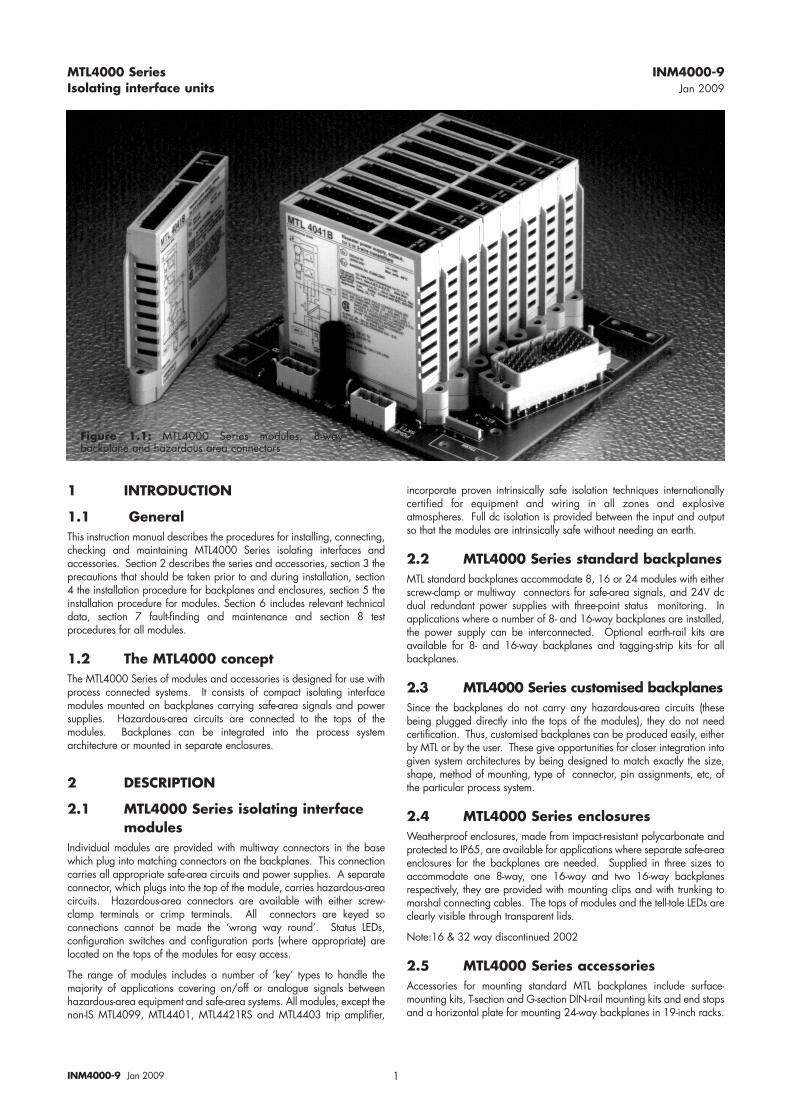
Figure 1.1: MTL4000 Series modules, 8-waybackplane and hazardous area connectors
2INM4000-9 Jan 2009
3 INSTALLATION – PRECAUTIONS
3.1 GeneralPlease read this section before beginning to install backplanes,enclosures, modules etc.
3.2 Precautionsa) Make sure that all installation work is carried out in
accordance with all relevant local standards, codes ofpractice and site regulations.
b) Check that the hazardous-area equipment complies with thedescriptive system document.
c) If in doubt, refer to the certificate/catalogue for clarificationof any aspects of intrinsic safety, or contact MTL or your localMTL representative for assistance.
d) Note that the units MUST NOT be installed in a hazardousarea unless protected by a locally acceptable explosion-prooftechnique.
e) Check that the interface unit(s) function(s) are correct for theapplication(s).
f) When plugging modules into backplanes and hazardous-area connectors into modules, check the identification labelsto make sure the items are mated correctly.
4 INSTALLATION – BACKPLANES andENCLOSURES
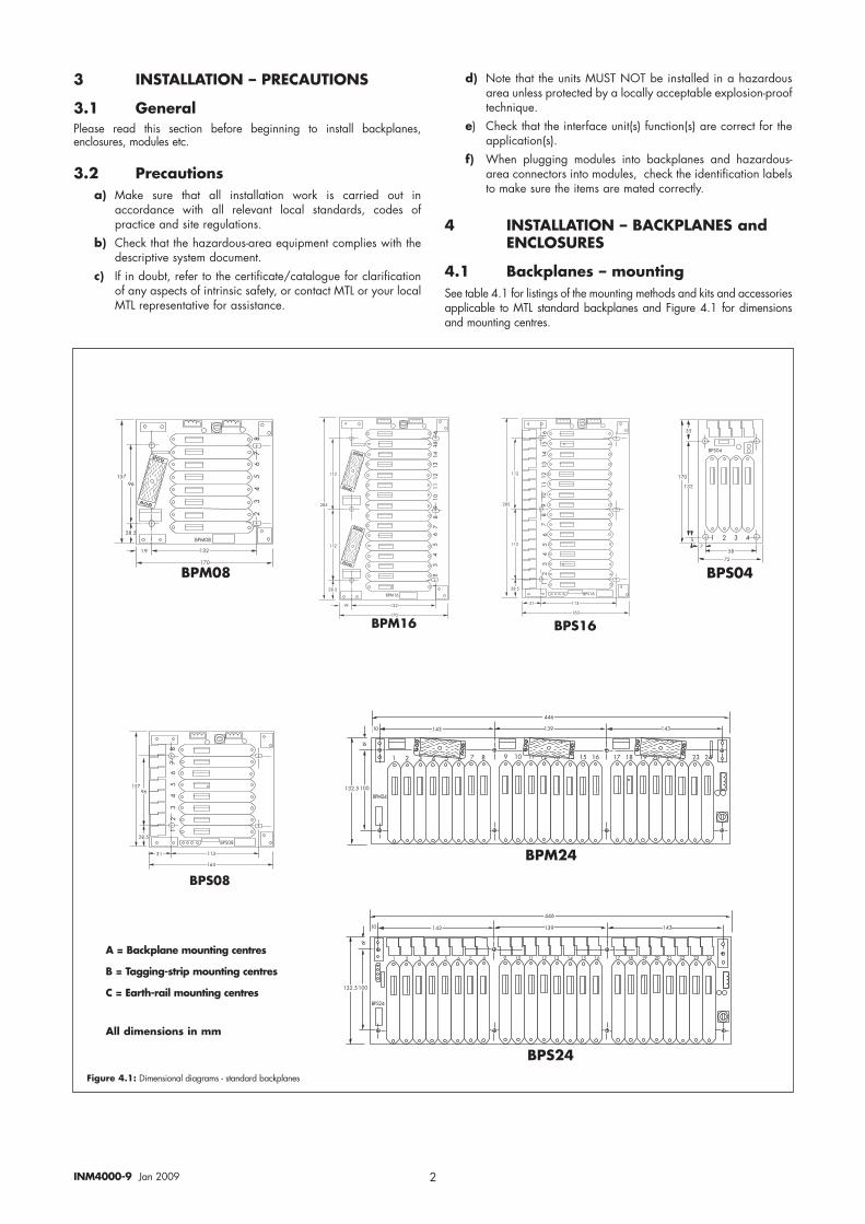
4.1 Backplanes – mounting See table 4.1 for listings of the mounting methods and kits and accessoriesapplicable to MTL standard backplanes and Figure 4.1 for dimensionsand mounting centres.
Figure 4.1: Dimensional diagrams - standard backplanes
A = Backplane mounting centres
B = Tagging-strip mounting centres
C = Earth-rail mounting centres
All dimensions in mm
���
���
����
���
���
����
���
���
��
�
���
��
���
���
��
����
��������
��
����
���
��
���
���
��
���
���
����
���
���
����
���
���
���
����
�����
��
����
����
���
�����
�����
�����
�
�����
���
����
�����
��
����
����
�
���
��
����
���
���
���
���
��
���
���
����
���
���
����
���
���
����
�����
�����
����
����
��
��� ���
���
���
���
���
����
���
���
����
���
���
����
��
�
����
����
��
��
��������
���
� � � � ���������������������������
��� ���
���
� � � � � � � � � � � � � � � � � � � � � � � � � � �������������������������� ������������������������� ���������������������������
���
��
��
����
��������
���
���� �������������������
��� ���
���
�������������������������� ������������������ ���������������� ������������������
����
� � � �
����
�
���
��
��
�
�
����
INM4000-9 Jan 2009
�����������������
�!�������������
���"���##�������
�$�����%���&!���
��'�(������!��)
*�(�������+��������
���"���##�&������
3
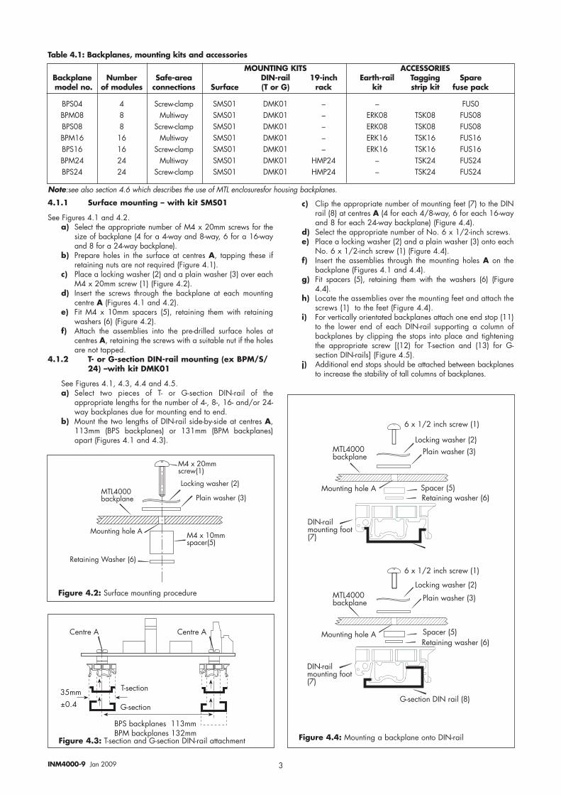
4.1.1 Surface mounting – with kit SMS01
See Figures 4.1 and 4.2.a) Select the appropriate number of M4 x 20mm screws for the
size of backplane (4 for a 4-way and 8-way, 6 for a 16-wayand 8 for a 24-way backplane).
b) Prepare holes in the surface at centres A, tapping these ifretaining nuts are not required (Figure 4.1).
c) Place a locking washer (2) and a plain washer (3) over eachM4 x 20mm screw (1) (Figure 4.2).
d) Insert the screws through the backplane at each mountingcentre A (Figures 4.1 and 4.2).
e) Fit M4 x 10mm spacers (5), retaining them with retainingwashers (6) (Figure 4.2).
f) Attach the assemblies into the pre-drilled surface holes atcentres A, retaining the screws with a suitable nut if the holesare not tapped.
4.1.2 T- or G-section DIN-rail mounting (ex BPM/S/24) –with kit DMK01
See Figures 4.1, 4.3, 4.4 and 4.5.a) Select two pieces of T- or G-section DIN-rail of the
appropriate lengths for the number of 4-, 8-, 16- and/or 24-way backplanes due for mounting end to end.
b) Mount the two lengths of DIN-rail side-by-side at centres A,113mm (BPS backplanes) or 131mm (BPM backplanes)apart (Figures 4.1 and 4.3).
c) Clip the appropriate number of mounting feet (7) to the DINrail (8) at centres A (4 for each 4/8-way, 6 for each 16-wayand 8 for each 24-way backplane) (Figure 4.4).
d) Select the appropriate number of No. 6 x 1/2-inch screws. e) Place a locking washer (2) and a plain washer (3) onto each
No. 6 x 1/2-inch screw (1) (Figure 4.4).f) Insert the assemblies through the mounting holes A on the
backplane (Figures 4.1 and 4.4). g) Fit spacers (5), retaining them with the washers (6) (Figure
4.4).h) Locate the assemblies over the mounting feet and attach the
screws (1) to the feet (Figure 4.4).i) For vertically orientated backplanes attach one end stop (11)
to the lower end of each DIN-rail supporting a column ofbackplanes by clipping the stops into place and tighteningthe appropriate screw [(12) for T-section and (13) for G-section DIN-rails] (Figure 4.5).
j) Additional end stops should be attached between backplanesto increase the stability of tall columns of backplanes.
,��(���),��(���)
$-���(���
.-���(���
��##
/���
���%���&!���������## ���%���&!��������##
MOUNTING KITS ACCESSORIESBackplane Number Safe-area DIN-rail 19-inch Earth-rail Tagging Sparemodel no. of modules connections Surface (T or G) rack kit strip kit fuse pack
BPS04 4 Screw-clamp SMS01 DMK01 – – FUS0BPM08 8 Multiway SMS01 DMK01 – ERK08 TSK08 FUS08BPS08 8 Screw-clamp SMS01 DMK01 – ERK08 TSK08 FUS08BPM16 16 Multiway SMS01 DMK01 – ERK16 TSK16 FUS16BPS16 16 Screw-clamp SMS01 DMK01 – ERK16 TSK16 FUS16BPM24 24 Multiway SMS01 DMK01 HMP24 – TSK24 FUS24BPS24 24 Screw-clamp SMS01 DMK01 HMP24 – TSK24 FUS24
Figure 4.3: T-section and G-section DIN-rail attachment
Figure 4.2: Surface mounting procedure
��"��0���������������
��"��0���������������
�����������������
�����������������
�!�������������
�!�������������
�$�����%���&!���
�$�����%���&!���
��'�(������!��)
��'�(������!��)
�&�������
�&�������
*�(����������������
*�(����������������
123-���!#�'�(����4��(�
123-���!#�'�(����4��(�
.-���(����123����!��
Note:see also section 4.6 which describes the use of MTL enclosuresfor housing backplanes.
Table 4.1: Backplanes, mounting kits and accessories
Figure 4.4: Mounting a backplane onto DIN-rail
4INM4000-9 Jan 2009
Table 4.2: MTL4000 Series top label colour coding
$-���(������
$-���(������
.-���(������ .-���(���
���
5�"����������
6�7��(�&���
8*
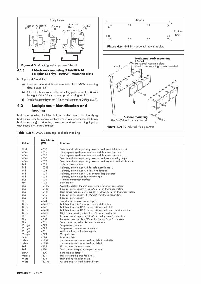
4.1.3 19-inch rack mounting (BPM/BPS/24 backplanes only) – HMP24 mounting plate
See Figures 4.6 and 4.7.
a) Place an unloaded backplane onto the HMP24 mountingplate (Figure 4.6).
b) Attach the backplane to the mounting plate at centres A withthe eight M4 x 12mm screws provided (Figure 4.6).
c) Attach the assembly to the 19-inch rack centres at D (Figure 4.7).
4.2 Backplanes – identification andtagging
Backplane labelling facilities include marked areas for identifyingbackplanes, specific module locations and system connections (multiwaybackplanes only). Mounting holes for earth-rail and tagging-stripattachments are similarly marked
Module no.Colour (MTL) Function
Black 4013 Two-channel switch/proximity detector interface, solid-state outputWhite 4014 Switch/proximity detector interface, with line fault detectionWhite 4015 Switch/proximity detector interface, with line fault detectionWhite 4016 Two-channel switch/proximity detector interface, dual relay outputWhite 4017 Two-channel switch/proximity detector interface, with line fault detectionRed 4021 Solenoid/alarm driverRed 4021S Solenoid/alarm driver, with fail-safe override facilityRed 4023 Solenoid/alarm driver, with line fault detectionRed 4024 Solenoid/alarm driver for 24V systems, loop poweredRed 4025 Solenoid/alarm driver, low current outputBlue 4031 Vibration transducer interfacePink 4032 Pulse isolatorBlue 4041A Current repeater, 4/20mA passive input for smart transmittersBlue 4041B Repeater power supply, 4/20mA, for 2- or 3-wire transmittersBlue 4041P High-power repeater power supply, 4/20mA, for 2- or 3-wire transmittersBlue 4042 Repeater power supply IIB, 4/20mA, for 2-wire transmittersBlue 4043 Repeater power supplyBlue 4044 Two channel repeater power supplyGreen 4045B/C Isolating driver, 4/20mA, with line fault detectionGreen 4046 Isolating driver, for HART valve positioners with LFDGreen 4046C Isolating driver, for HART valve positioners with open-circuit detectionGreen 4046P High-power isolating driver, for HART valve positionersBlue 4047 Repeater power supply, 4/20mA, for Bailey ‘smart’ transmittersBlue 4048 Repeater power supply, 4/20mA, for Foxboro ‘smart’ transmittersBlue 4061 Two-channel fire and smoke detector interfaceOrange 4073 Temperature converterOrange 4075 Temperature converter, with trip alarmOrange 4081 Millivolt isolator, for low-level signalsOrange 4083 Voltage isolatorGrey 4099 Dummy isolatorYellow 4113P Switch/proximity detector interface, fail-safe, with LFDYellow 4114P Switch/proximity detector interface, fail-safeRed 4215 IS-output switch-operated relayRed 4216 Two-channel IS-output switch-operated relayBrown 4220 Earth leakage detectorMaroon 4401 Honeywell DE trip amplifier, non ISWhite 4403 High-level trip amplifier, non IS White 4421RS General purpose switch operated relay
��##
�����##��9
) ) ) )1
1
1
1) ) ) )
Figure 4.6: HMP24 Horizontal mounting plate
�������
9����������'�4����#�'�(������(� �������������
�� �������� ������������:����:���;��(�!�#�'�(����&!�(�� ���&!����#�'�(�����������&��<�7�7
Figure 4.7: 19-inch rack fixing centres
Figure 4.5: Mounting end stops onto DIN-rail
5INM4000-9 Jan 2009
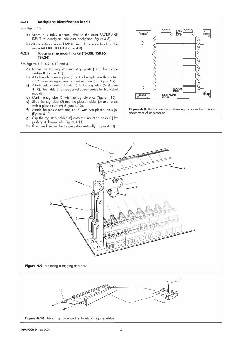
4.21 Backplane identification labels
See Figure 4.8.
a) Attach a suitably marked label to the area BACKPLANEIDENT. to identify an individual backplane (Figure 4.8).
b) Attach suitably marked MPL01 module position labels to theareas MODULE IDENT (Figure 4.8).
4.2.2 Tagging strip mounting kit (TSK08, TSK16, TSK24)
See Figures 4.1, 4.9, 4.10 and 4.11.a) Locate the tagging strip mounting posts (1) at backplane
centres B (Figure 4.1).b) Attach each mounting post (1) to the backplane with two M3
x 12mm mounting screws (2) and washers (3) (Figure 4.9).c) Attach colour coding labels (4) to the tag label (5) (Figure
4.10). See table 2 for suggested colour codes for individualmodules.
d) Mark the tag label (5) with the tag reference (Figure 4.10).e) Slide the tag label (5) into the plastic holder (6) and retain
with a plastic rivet (9) (Figure 4.10).f) Attach the plastic retaining tie (7) with two plastic rivets (8)
(Figure 4.11).g) Clip the tag strip holder (6) onto the mounting posts (1) by
pushing it downwards (Figure 4.11).h) If required, swivel the tagging strip vertically (Figure 4.11)
����
���� � ���
� ����!"��#!$�%&�$�
�'&(#�%&�$�
�
�
�
� �
�
Figure 4.8: Backplane layout showing locations for labels andattachment of accessories
Figure 4.9: Mounting a tagging-strip post
�
�
�
�
Figure 4.10: Attaching colour-coding labels to tagging -strips
6INM4000-9 Jan 2009
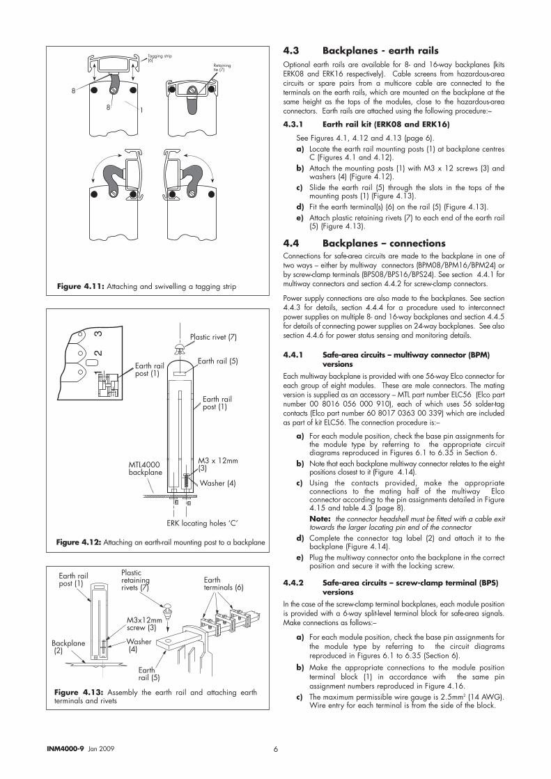
4.3 Backplanes - earth railsOptional earth rails are available for 8- and 16-way backplanes (kitsERK08 and ERK16 respectively). Cable screens from hazardous-areacircuits or spare pairs from a multicore cable are connected to theterminals on the earth rails, which are mounted on the backplane at thesame height as the tops of the modules, close to the hazardous-areaconnectors. Earth rails are attached using the following procedure:–
4.3.1 Earth rail kit (ERK08 and ERK16)
See Figures 4.1, 4.12 and 4.13 (page 6).a) Locate the earth rail mounting posts (1) at backplane centres
C (Figures 4.1 and 4.12).b) Attach the mounting posts (1) with M3 x 12 screws (3) and
washers (4) (Figure 4.12).c) Slide the earth rail (5) through the slots in the tops of the
mounting posts (1) (Figure 4.13).d) Fit the earth terminal(s) (6) on the rail (5) (Figure 4.13).e) Attach plastic retaining rivets (7) to each end of the earth rail
(5) (Figure 4.13).
4.4 Backplanes – connections Connections for safe-area circuits are made to the backplane in one oftwo ways – either by multiway connectors (BPM08/BPM16/BPM24) orby screw-clamp terminals (BPS08/BPS16/BPS24). See section 4.4.1 formultiway connectors and section 4.4.2 for screw-clamp connectors.
Power supply connections are also made to the backplanes. See section4.4.3 for details, section 4.4.4 for a procedure used to interconnectpower supplies on multiple 8- and 16-way backplanes and section 4.4.5for details of connecting power supplies on 24-way backplanes. See alsosection 4.4.6 for power status sensing and monitoring details.
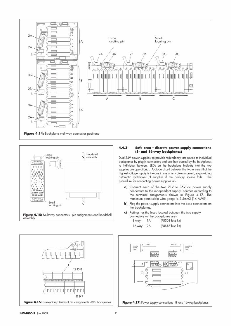
4.4.1 Safe-area circuits – multiway connector (BPM)versions
Each multiway backplane is provided with one 56-way Elco connector foreach group of eight modules. These are male connectors. The matingversion is supplied as an accessory – MTL part number ELC56 (Elco partnumber 00 8016 056 000 910), each of which uses 56 solder-tagcontacts (Elco part number 60 8017 0363 00 339) which are includedas part of kit ELC56. The connection procedure is:–
a) For each module position, check the base pin assignments forthe module type by referring to the appropriate circuitdiagrams reproduced in Figures 6.1 to 6.35 in Section 6.
b) Note that each backplane multiway connector relates to the eightpositions closest to it (Figure 4.14).
c) Using the contacts provided, make the appropriateconnections to the mating half of the multiway Elcoconnector according to the pin assignments detailed in Figure4.15 and table 4.3 (page 8).Note: the connector headshell must be fitted with a cable exittowards the larger locating pin end of the connector
d) Complete the connector tag label (2) and attach it to thebackplane (Figure 4.14).
e) Plug the multiway connector onto the backplane in the correctposition and secure it with the locking screw.
4.4.2 Safe-area circuits – screw-clamp terminal (BPS)versions
In the case of the screw-clamp terminal backplanes, each module positionis provided with a 6-way split-level terminal block for safe-area signals.Make connections as follows:–
a) For each module position, check the base pin assignments forthe module type by referring to the circuit diagramsreproduced in Figures 6.1 to 6.35 (Section 6).
b) Make the appropriate connections to the module positionterminal block (1) in accordance with the same pinassignment numbers reproduced in Figure 4.16.
c) The maximum permissible wire gauge is 2.5mm2 (14 AWG).Wire entry for each terminal is from the side of the block.
6��(�����!&��(���
�!��(����(��������<�(���
6��(�(��#���!����
6��(����!���
���&!������
��"��##��������
+��������
� �
�!��(�����<�(��
6��(�����!���
6��(�����!&��(���
���"���##��
+��������
�$�����%���&!���
6*=�!���(������!���>,?
�����������
6��(�����!&��(���
$��������(��&��
*�(������(����
�
Figure 4.11: Attaching and swivelling a tagging strip
Figure 4.12: Attaching an earth-rail mounting post to a backplane
Figure 4.13: Assembly the earth rail and attaching earthterminals and rivets
7INM4000-9 Jan 2009
4.4.3 Safe area – discrete power supply connections(8- and 16-way backplanes)
Dual 24V power supplies, to provide redundancy, are routed to individualbackplanes by plug-in connectors and are then bussed by the backplanesto individual isolators. LEDs on the backplane indicate that the twosupplies are operational. A diode circuit between the two ensures that thehighest voltage supply is the one in use at any given moment, so providingautomatic switchover of supplies if the primary source fails. Theprocedure for connecting power supplies is:–
a) Connect each of the two 21V to 35V dc power supplyconnectors to the independent supply sources according tothe terminal assignments shown in Figure 4.17. Themaximum permissible wire gauge is 2.5mm2 (14 AWG).
b) Plug the power supply connectors into the base connectors onthe backplanes.
c) Ratings for the fuses located between the two supply connectors on the backplanes are:-
8-way: 1A (FUS08 fuse kit)
16-way: 2A (FUS16 fuse kit)
)
�)
�)
)
�
�
�)
�)
�����!���(����&��
) ,
�) �) � � �, �,
�#�!!!���(����&��
��������������������������
��������������
���������
�������
�����
�����
�
����
��������������������������
���
���
����
���� ��������������������������������������������� ������������������ ���������������� ������������������
� � � �
� � � � � �
� � � � �� � � �
� � � �� �
� � ! " #$ % & '
( ) * + ,��--��--��---.
��-- --��--����--��------��
/0
1
2
3
/
1
0 2
3
�����!���(����&��
�#�!!!���(����&��
:��7���!!����#%!@
�A �+*� �A �+*�
���#��@������'&&!@
� ������7��@������'&&!@
�=$�� �=$��
�+*�B�� �+*�B��
Figure 4.15: Multiway connectors - pin assignments and headshellassembly
Figure 4.17: Power supply connections - 8- and 16-way backplanes
Figure 4.14: Backplane multiway connector positions
��������
�������
�
� �
Figure 4.16: Screw-clamp terminal pin assignments - BPS backplanes
8INM4000-9 Jan 2009
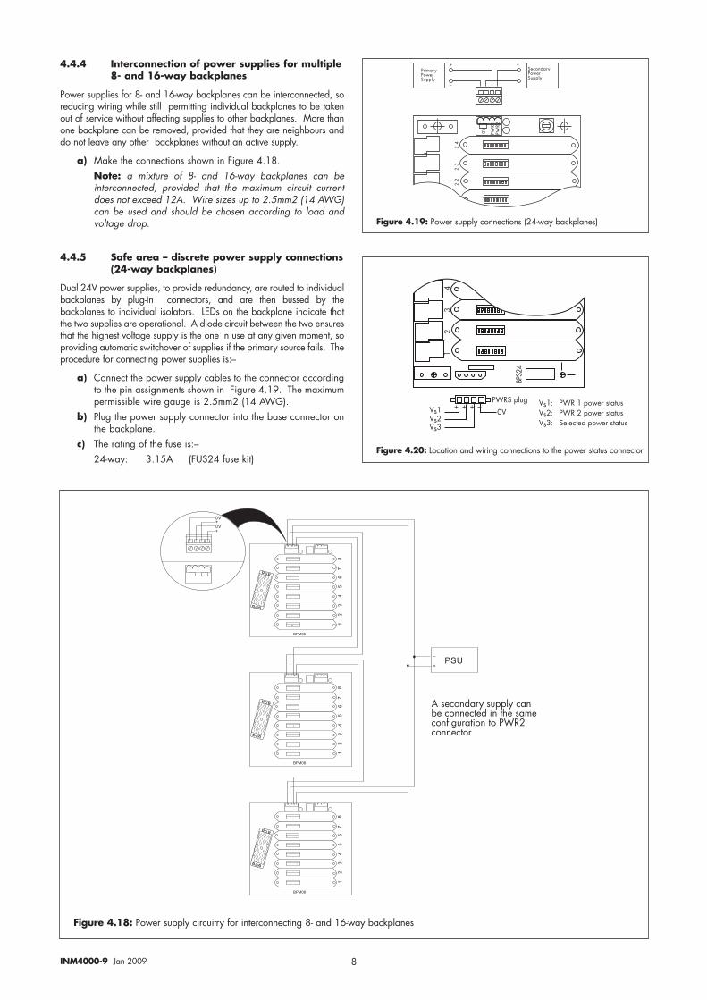
4.4.4 Interconnection of power supplies for multiple8- and 16-way backplanes
Power supplies for 8- and 16-way backplanes can be interconnected, soreducing wiring while still permitting individual backplanes to be takenout of service without affecting supplies to other backplanes. More thanone backplane can be removed, provided that they are neighbours anddo not leave any other backplanes without an active supply.
a) Make the connections shown in Figure 4.18.Note: a mixture of 8- and 16-way backplanes can beinterconnected, provided that the maximum circuit currentdoes not exceed 12A. Wire sizes up to 2.5mm2 (14 AWG)can be used and should be chosen according to load andvoltage drop.
4.4.5 Safe area – discrete power supply connections(24-way backplanes)
Dual 24V power supplies, to provide redundancy, are routed to individualbackplanes by plug-in connectors, and are then bussed by thebackplanes to individual isolators. LEDs on the backplane indicate thatthe two supplies are operational. A diode circuit between the two ensuresthat the highest voltage supply is the one in use at any given moment, soproviding automatic switchover of supplies if the primary source fails. Theprocedure for connecting power supplies is:–
a) Connect the power supply cables to the connector accordingto the pin assignments shown in Figure 4.19. The maximumpermissible wire gauge is 2.5mm2 (14 AWG).
b) Plug the power supply connector into the base connector onthe backplane.
c) The rating of the fuse is:–24-way: 3.15A (FUS24 fuse kit)
�A
�+*�
���#��@������'&&!@
C
B
�����7��@������'&&!@
��
��
��
��
��
��
�+*�
C
������������������������
�����
� ���
������������������������
�����
� ���
������������������������
�����
� ���
��
���
�
�
� ��
)������7��@��'&&!@����%��������(�7����(�����#����4��'��(����(���+*�������(��
Figure 4.20: Location and wiring connections to the power status connector
Figure 4.19: Power supply connections (24-way backplanes)
Figure 4.18: Power supply circuitry for interconnecting 8- and 16-way backplanes
���
�
���
���
����
���
���
A��A��A��
�A
�+*��&!'�C�C�C�B A��D �+*���&������(�('�
A��D �+*���&������(�('�A��D ��!��(�7�&������(�('�
9INM4000-9 Jan 2009
4.4.6 Power supply status
Three sensing points, connected to safe-area circuit terminals, monitor thepower supply voltages to provide the process system with statusindication. Output voltages to the process system are current limited by10kΩ resistors. On BPS backplanes, the monitoring connections to thesystem are made through a separate power status connector (Figure4.20). This separate connector is not needed on BPM backplanes as theconnection is made through pins EE to KK on the multiway connectorscarrying safe-area signals.
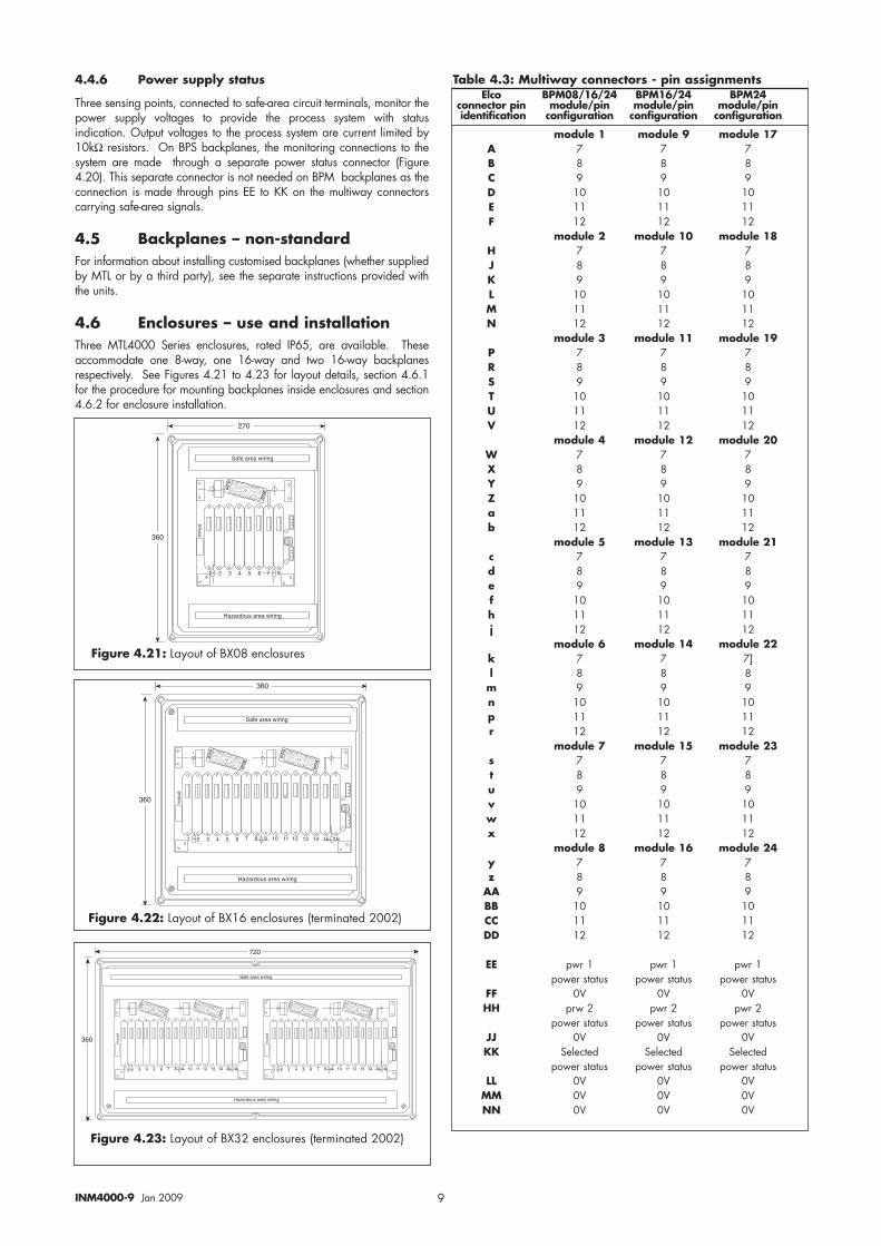
4.5 Backplanes – non-standard For information about installing customised backplanes (whether suppliedby MTL or by a third party), see the separate instructions provided withthe units.
4.6 Enclosures – use and installation Three MTL4000 Series enclosures, rated IP65, are available. Theseaccommodate one 8-way, one 16-way and two 16-way backplanesrespectively. See Figures 4.21 to 4.23 for layout details, section 4.6.1for the procedure for mounting backplanes inside enclosures and section4.6.2 for enclosure installation.
�������������������������� � � �
���
���
��
����������������
������ !"������������
Elco BPM08/16/24 BPM16/24 BPM24connector pin module/pin module/pin module/pinidentification configuration configuration configuration
module 1 module 9 module 17A 7 7 7B 8 8 8C 9 9 9D 10 10 10E 11 11 11F 12 12 12
module 2 module 10 module 18H 7 7 7J 8 8 8K 9 9 9L 10 10 10M 11 11 11N 12 12 12
module 3 module 11 module 19P 7 7 7R 8 8 8S 9 9 9T 10 10 10U 11 11 11V 12 12 12
module 4 module 12 module 20W 7 7 7X 8 8 8Y 9 9 9Z 10 10 10a 11 11 11b 12 12 12
module 5 module 13 module 21c 7 7 7d 8 8 8e 9 9 9f 10 10 10h 11 11 11 j 12 12 12
module 6 module 14 module 22k 7 7 7]l 8 8 8
m 9 9 9n 10 10 10p 11 11 11r 12 12 12
module 7 module 15 module 23s 7 7 7t 8 8 8u 9 9 9v 10 10 10w 11 11 11x 12 12 12
module 8 module 16 module 24y 7 7 7z 8 8 8
AA 9 9 9BB 10 10 10CC 11 11 11DD 12 12 12
EE pwr 1 pwr 1 pwr 1power status power status power status
FF 0V 0V 0VHH prw 2 pwr 2 pwr 2
power status power status power statusJJ 0V 0V 0VKK Selected Selected Selected
power status power status power statusLL 0V 0V 0V
MM 0V 0V 0VNN 0V 0V 0V
Table 4.3: Multiway connectors - pin assignments
Figure 4.21: Layout of BX08 enclosures
Figure 4.22: Layout of BX16 enclosures (terminated 2002)
���
���
����������������
������ !"������������
�������������������������� ����������������������� ������������������
����
Figure 4.23: Layout of BX32 enclosures (terminated 2002)
���
��
����������������
�������������������������� ����������������������� ������������������
����
�������������������������� ����������������������� ������������������
����
������ !"������������
10INM4000-9 Jan 2009
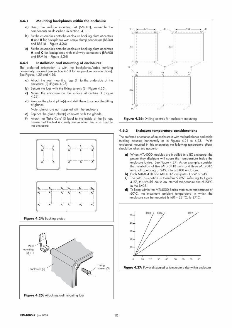
4.6.1 Mounting backplanes within the enclosure
a) Using the surface mounting kit (SMS01), assemble thecomponents as described in section 4.1.1.
b) Fix the assemblies onto the enclosure backing plate at centresA and B for backplanes with screw clamp connectors (BPS08and BPS16 – Figure 4.24)
c) Fix the assemblies onto the enclosure backing plate at centresA and C for backplanes with multiway connectors (BPM08and BPM16 – Figure 4.24)
4.6.2 Installation and mounting of enclosures The preferred orientation is with the backplanes/cable trunkinghorizontally mounted (see section 4.6.3 for temperature considerations).See Figures 4.25 and 4.26.
a) Attach the wall mounting lugs (1) to the underside of theenclosure (2) (Figure 4.25).
b) Secure the lugs with the fixing screws (3) (Figure 4.25).c) Mount the enclosure on the surface at centres D (Figure
4.26).d) Remove the gland plate(s) and drill them to accept the fitting
of glands. Note: glands are not supplied with the enclosure
e) Replace the gland plate(s) complete with the glands.f) Attach the ‘Take Care’ IS label to the inside of the lid top.
Ensure that the text is clearly visible when the lid is fixed tothe enclosure.
4.6.3 Enclosure temperature considerations
The preferred orientation of an enclosure is with the backplanes and cabletrunking mounted horizontally as in Figures 4.21 to 4.23. Withenclosures mounted in this orientation the following temperature effectsshould be taken into account:–
a) When MTL4000 modules are installed in a BX enclosure, thepower they dissipate will cause the temperature inside theenclosure to rise. See Figure 4.27. As an example, considerthe installation of five MTL4041B units and three MTL4016units, all operating at 24V, into a BX08 enclosure.
b) Each MTL4041B and MTL4016 dissipates 1.2W at 24V.c) The total dissipation is therefore 9.6W. Referring to Figure
4.27, this would cause an internal temperature rise of 23°Cin the BX08.
d) To keep within the MTL4000 Series maximum temperature of60°C, the maximum ambient temperature in which theenclosure can be mounted is (60 – 23)°C, ie 37°C.
" " "
� � �
! ! !
" "
� �
! !
"�
��
!�
"�
��
!�
"�
��
!�
"
�
!
"
�
!
"
�
!
���
���
���
���
���
��� ���
1 1 1
1 11
1 1 1
Figure 4.25: Attaching wall mounting lugs
Figure 4.26: Drilling centres for enclosure mounting
Figure 4.24: Backing plates
+�!!#�'�(���
!'����
6��!��'����� 5�"������������
�� �� �� �� �� �� � ��
��
��
��
��
�� E� E�� E��
Figure 4.27: Power dissipated vs temperature rise within enclosure
11INM4000-9 Jan 2009
5 INSTALLATION – MODULESWARNING: When installing MTL4000 Series isolators it isessential to make sure that intrinsically- safe and non-intrinsically-safe wiring is segregated as required by anationally accepted authority or as described in BS 5345, ISARP 12.6 or DIN VDE-165.
WARNING: Make sure the correct hazardous-area connector(field-wiring plug) is plugged into the correspondingisolator. It is recommended that the connector is identifiedby the same tag number as the matching isolator.
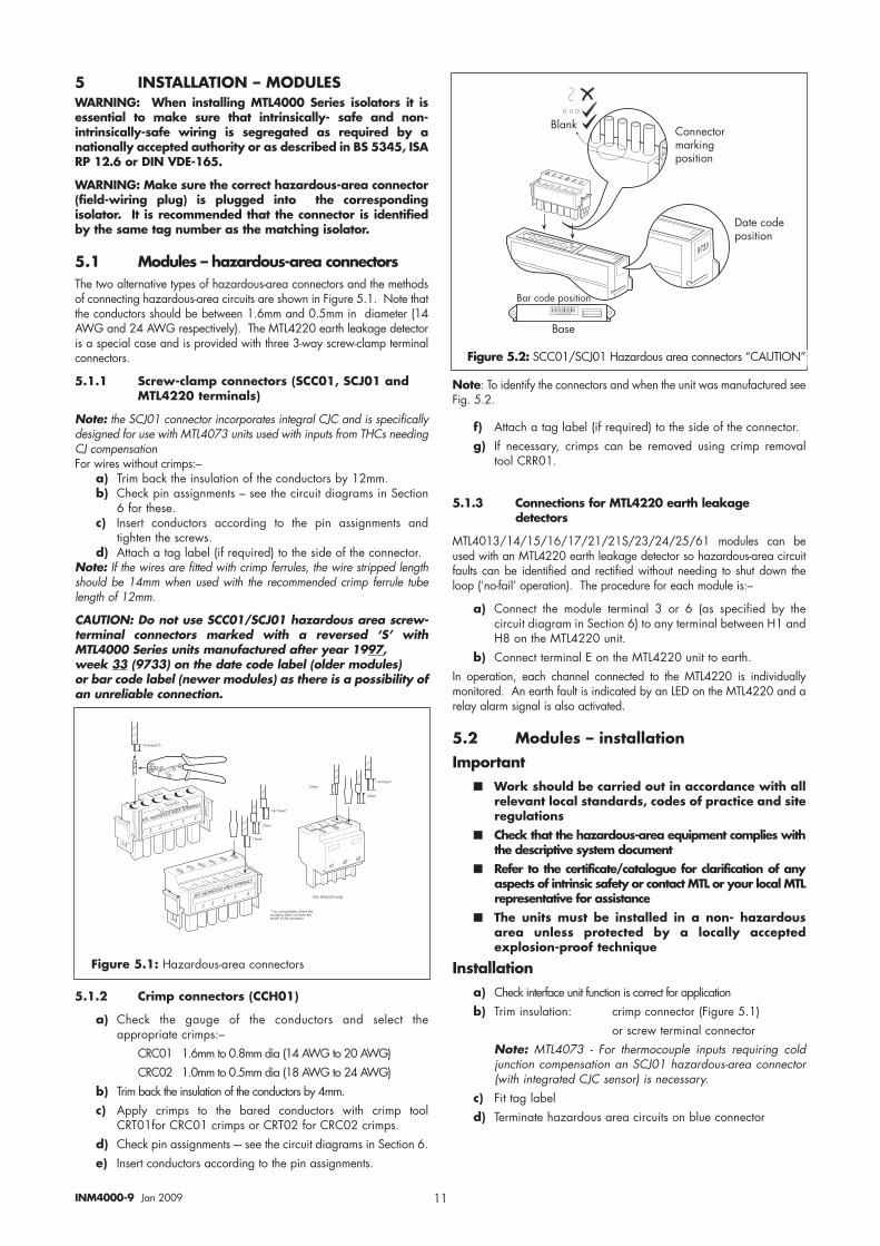
5.1 Modules – hazardous-area connectors The two alternative types of hazardous-area connectors and the methodsof connecting hazardous-area circuits are shown in Figure 5.1. Note thatthe conductors should be between 1.6mm and 0.5mm in diameter (14AWG and 24 AWG respectively). The MTL4220 earth leakage detectoris a special case and is provided with three 3-way screw-clamp terminalconnectors.
5.1.1 Screw-clamp connectors (SCC01, SCJ01 andMTL4220 terminals)
Note: the SCJ01 connector incorporates integral CJC and is specificallydesigned for use with MTL4073 units used with inputs from THCs needingCJ compensation For wires without crimps:–
a) Trim back the insulation of the conductors by 12mm.b) Check pin assignments – see the circuit diagrams in Section
6 for these.c) Insert conductors according to the pin assignments and
tighten the screws.d) Attach a tag label (if required) to the side of the connector.
Note: If the wires are fitted with crimp ferrules, the wire stripped lengthshould be 14mm when used with the recommended crimp ferrule tubelength of 12mm.
CAUTION: Do not use SCC01/SCJ01 hazardous area screw-terminal connectors marked with a reversed ‘S’ withMTL4000 Series units manufactured after year 1997, week 33 (9733) on the date code label (older modules) or bar code label (newer modules) as there is a possibility ofan unreliable connection.
Note: To identify the connectors and when the unit was manufactured seeFig. 5.2.
f) Attach a tag label (if required) to the side of the connector.g) If necessary, crimps can be removed using crimp removal
tool CRR01.
5.1.3 Connections for MTL4220 earth leakagedetectors
MTL4013/14/15/16/17/21/21S/23/24/25/61 modules can beused with an MTL4220 earth leakage detector so hazardous-area circuitfaults can be identified and rectified without needing to shut down theloop (‘no-fail’ operation). The procedure for each module is:–
a) Connect the module terminal 3 or 6 (as specified by thecircuit diagram in Section 6) to any terminal between H1 andH8 on the MTL4220 unit.
b) Connect terminal E on the MTL4220 unit to earth.In operation, each channel connected to the MTL4220 is individuallymonitored. An earth fault is indicated by an LED on the MTL4220 and arelay alarm signal is also activated.
5.2 Modules – installation Important
■■ Work should be carried out in accordance with allrelevant local standards, codes of practice and siteregulations
■■ Check that the hazardous-area equipment complies withthe descriptive system document
■■ Refer to the certificate/catalogue for clarification of anyaspects of intrinsic safety or contact MTL or your local MTLrepresentative for assistance
■■ The units must be installed in a non- hazardousarea unless protected by a locally acceptedexplosion-proof technique
Installation a) Check interface unit function is correct for application b) Trim insulation: crimp connector (Figure 5.1)
or screw terminal connector Note: MTL4073 - For thermocouple inputs requiring coldjunction compensation an SCJ01 hazardous-area connector(with integrated CJC sensor) is necessary.
c) Fit tag labeld) Terminate hazardous area circuits on blue connector
���##/���
�#$��%&%'()
���%'*%�#*'�+
,%$�
� � � � ��
��##
�#$��%&%'()
���%'*%�#*'�+
,%$�
� � � � ��
��##
��-��##F
���� ��
��##
��##
��-��##F
5�4����$��������!@
F�4������#&�%!�7���������(�����'!�(����7������(���(���(��#�'(���4�(���������(��
!���,�����(��#������&���(���
1�(����7�&���(���
���
����
� � � � � � � �
�����7��&���(���
5.1.2 Crimp connectors (CCH01)
a) Check the gauge of the conductors and select theappropriate crimps:–
CRC01 1.6mm to 0.8mm dia (14 AWG to 20 AWG)CRC02 1.0mm to 0.5mm dia (18 AWG to 24 AWG)
b) Trim back the insulation of the conductors by 4mm.c) Apply crimps to the bared conductors with crimp tool
CRT01for CRC01 crimps or CRT02 for CRC02 crimps.d) Check pin assignments -– see the circuit diagrams in Section 6.e) Insert conductors according to the pin assignments.
Figure 5.1: Hazardous-area connectors
Figure 5.2: SCC01/SCJ01 Hazardous area connectors “CAUTION”
12INM4000-9 Jan 2009
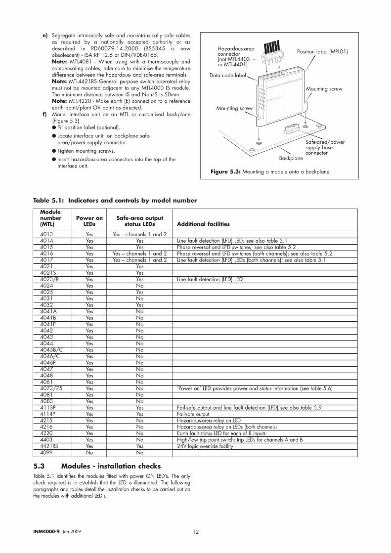
e) Segregate intrinsically safe and non-intrinsically safe cablesas required by a nationally accepted authority or asdescribed in PD60079.14:2000 (BS5345 is nowobsolescent) - ISA RP 12.6 or DIN/VDE-0165.Note: MTL4081 - When using with a thermocouple andcompensating cables, take care to minimise the temperaturedifference between the hazardous- and safe-area terminalsNote: MTL4421RS General purpose switch operated relaymust not be mounted adjacent to any MTL4000 IS module.The minimum distance between IS and Non-IS is 50mmNote: MTL4220 - Make earth (E) connection to a referenceearth point/plant OV point as directed.
f) Mount interface unit on an MTL or customised backplane(Figure 5.3)● Fit position label (optional).● Locate interface unit on backplane safe-
area/power supply connector.● Tighten mounting screws.● Insert hazardous-area connectors into the top of the
interface unit.
� � � � � �
����(����!�%�!�������
��'�(���������
��'�(���������
���&!���
��4�-����0&�����'&&!@�%���������(��
:�;��7�'�-����������(�����(��$���������$�����
1�(����7��!�%�!
Modulenumber Power on Safe-area output(MTL) LEDs status LEDs Additional facilities
4013 Yes Yes – channels 1 and 24014 Yes Yes Line fault detection (LFD) LED; see also table 5.14015 Yes Yes Phase reversal and LFD switches; see also table 5.24016 Yes Yes – channels 1 and 2 Phase reversal and LFD switches (both channels); see also table 5.2 4017 Yes Yes – channels 1 and 2 Line fault detection (LFD) LEDs (both channels); see also table 5.14021 Yes Yes4021S Yes Yes4023/R Yes Yes Line fault detection (LFD) LED4024 Yes No4025 Yes Yes4031 Yes No4032 Yes Yes4041A Yes No4041B Yes No4041P Yes No4042 Yes No4043 Yes No4044 Yes No4045B/C Yes No4046/C Yes No4046P Yes No4047 Yes No4048 Yes No4061 Yes No4073/75 Yes No ‘Power on’ LED provides power and status information (see table 5.6)4081 Yes No4083 Yes No4113P Yes Yes Fail-safe output and line fault detection (LFD) see also table 5.94114P Yes Yes Fail-safe output4215 Yes No Hazardous-area relay on LED4216 Yes No Hazardous-area relay on LEDs (both channels)4220 Yes No Earth fault status LED for each of 8 inputs4403 Yes No High/low trip point switch: trip LEDs for channels A and B4421RS Yes Yes 24V logic override facility4099 No No
5.3 Modules - installation checksTable 5.1 identifies the modules fitted with power ON LED’s. The onlycheck required is to establish that the LED is illuminated. The followingparagraphs and tables detail the installation checks to be carried out onthe modules with additional LED’s.
Table 5.1: Indicators and controls by model number
Figure 5.3: Mounting a module onto a backplane
13INM4000-9 Jan 2009
��#���)�+*�,:��,:�
�+*�G �����,:��G ,�����!��,:��G ,�����!��
��#�����+*
�51
20�
��#���*�+* ,:�
�5�
�5�
,:�
�+* G �����20� G ,�����!���(�('��51 G �����5�'!(�7�(��(���
�+* G� �����,:� G ,�����!���(�('�,:� G ,�����!����(�('��5� G �����5�'!(�7�(��(���
������!���5� G �����5�'!(�7�(��(���
������!��
Operation Input value Channel LED Channel relay LFD LED LFD relay
Normal >2.1mA On Closed Off Closed<1.2mA Off Open Off Closed
Broken line <50µA Off Open On OpenShorted line <100Ω Off Open On Open
Table 5.3: MTL4015/4016, table of test results(Results expected when sensor operated as shown)
Phase (PH)Operation Input value Direct-acting Reverse-acting LFD LED Relay output
<1.2mA On – On Off OpenNormal >2.1mA On – On On Closed
<1.2mA – On On On Closed>2.1mA – On On Off Open
<100µA On – On Off Open<100µA – On On Off Open
Broken line <100µA On – Off Off Open<100µA – On Off On Closed
>6.5mA On – On Off OpenShorted line >6.5mA – On On Off Open
>6.5mA On – Off On Closed>6.5mA – On Off Off Open
�+* ,:� ,:��$�����,:� *6A 12*�:�51
83 855,:� *6A 12*�:�51
83 855
�+* 83�$�����
*6A 12*�:�51
83 855
�+* G �����83 G ,�����!����(�('��51 G �����5�'!(�7�(��(����+* G �����,:� G ,�����!����(�('�,:� G ,�����!����(�('��51 G �����5�'!(�7�(��(����: G ������*�<����!
Figure 5.4: MTL4013 installation checks
Figure 5.5: MTL4014 & MTL4017 installation checks
Figure 5.6: MTL4015 & MTL4016 installation checks
Note: if line fault detection is switched on for switch sensors, make sure that the resistors (22kΩ and 620Ω) are fitted as shown in fugure 6.3 and 6.4
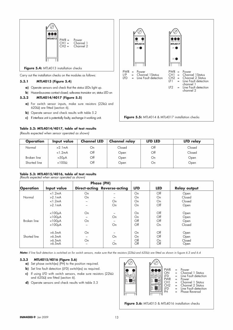
Carry out the installation checks on the modules as follows:
5.3.1 MTL4013 (Figure 5.4)
a) Operate sensors and check that the status LEDs light up.b) Hazardous-area contact closed; safe-area transistor on; status LED on
5.3.2 MTL4014/4017 (Figure 5.5)
a) For switch sensor inputs, make sure resistors (22kΩ and620Ω) are fitted (section 6).
b) Operate sensor and check results with table 5.2c) If interface unit is potentially faulty, exchange it working unit.
5.3.3 MTL4015/4016 (Figure 5.6)a) Set phase switch(es) (PH) to the position required.b) Set line fault detection (LFD) switch(es) as required.c) If using LFD with switch sensors, make sure resistors (22kΩ
and 620Ω) are fitted (section 6).d) Operate sensors and check results with table 5.3
Table 5.2: MTL4014/4017, table of test results(Results expected when sensor operated as shown)
14INM4000-9 Jan 2009
��#���
1��<� 80�
1��<� G 1��<���(�('�80� G 8'(&'(��(�('�
��#��)�+* 80�
)�
A�&�A�A
��A
)���
���
�+ �,+��-�.,/
�
)
�+* G �����80� G 8'(&'(��(�('�
��#��*)
�+*
,8352.
�+* G �����,8352. G ,��4��'��(���
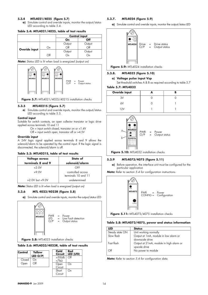
5.3.4 MTL4021/4025 (figure 5.7)a) Simulate control and overide inputs, monitor the output/status
LED according to table 5.4.
Control inputOn Off
Output OutputOn Off Off
Output OutputOff On On
5.3.5 MTL4021S (figure 5.7)a) Simulate control and overide inputs, monitor the output/status
LED according to table 5.5.Control inputSuitable for switch contacts, an open collector transistor or logic driveapplied across terminals 10 and 11
On = input switch closed, transistor on or <1.4V Off = input switch open, transistor off or >4.5V
Override inputA 24V logic signal applied across terminals 8 and 9 allows thesolenoid/alarm to be operated by the control input. If the logic signal isdisconnected, the solenoid/alarm is off.
Note: Status LED is lit when load is energized (output on)
��#���
�+* 80�
��#���
�+* 80�
��#��0
�+* 80�
�+* G �����80� G 8'(&'(��(�('�
Note: Status LED is lit when load is energized (output on)
5.3.6 MTL 4023/4023R (figure 5.8)
a) Simulate control and overide inputs, monitor the output/status LED
Table 5.6: MTL4023/4023R, table of test results
Voltage across State ofterminals 8 and 9 solenoid/alarm
<2.0V OFF>9.0V controlled across
terminals 10 and 11>2.0V but <9.0V undetermined
Table 5.5: MTL4021S, table of test results
Table 5.4: MTL4021/4025, table of test results
��#��)
�+* 80��51
�+* G ������51 G �����5�'!(�7�(��(���80� G 8'(&'(��(�('�
Control Yellow LED O/P)
Closed OnOpen Off
Field RedCircuit LED (LFD)>50Ω& Off<7kΩOpen OnCircuitShort OnCircuit
5.3.7. MTL4024 (figure 5.9)
a) Simulate control and overide inputs, monitor the output/status LED
5.3.8. MTL4032 (figure 5.10)
a) Voltage pulse input VspSet threshold switches A & B as required according to table 5.7
Table 5.7: MTL4032
Overide input A B
3V 0 0
6V 0 1
12V 1 1
5.3.9 MTL4073/4075 (figure 5.11)
a) Before operation, the interface unit must be configured for theparticular application
Note: Refer to section 5.4 for configuration instructions.
Table 5.8: MTL4073/4075, power and status information
LED StatusSteady state ON Unit working normallySlow flash Output at 1mA, module in low alarm or
downscale driveFast flash Output at 21mA, module in high alarm or
upscale driveOff No power to module
Note: Refer to section 5.4 for configuration data.
Figure 5.7: MTL4021/4025/4021S installation checks
Figure 5.9: MTL4024 installation checks
Figure 5.10: MTL4032 installation checks
Figure 5.11: MTL4073/4075 installation checks
Figure 5.8: MTL4023 installation checks
Overide input
15INM4000-9 Jan 2009
���������
�%-*#.�('+�*),������)--
��#����
�+*
�+* G �����
��#��0
�+* 80�
�+* G �����80� G 5��!-��4���'(&'(
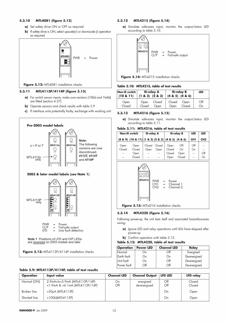
5.3.10 MTL4081 (figure 5.12)
a) Set safety drive ON or OFF as requiredb) If safety drive is ON, select upscale(+) or downscale (-) operation
as required
Figure 5.12: MTL4081 installation checks
Figure 5.14: MTL4215 installation checks
5.3.11 MTL4113P/4114P (figure 5.13)
a) For switch sensor inputs, make sure resistors (10kΩ and 1k4Ω)are fitted (section 6.27)
b) Operate sensors and check results with table 5.9c) If interface units potentially faulty, exchange with working unit
5.3.12 MTL4215 (figure 5.14)
a) Simulate safe-area input, monitor the output/status LEDaccording to table 5.10.
Table 5.9: MTL4113P/4114P, table of test results
Operation Input value Channel LED Channel Output LFD LED LFD relay
Normal (ON) 2.9mA<ls<3.9mA (MTL4113P/14P) On energised Off Closed<1.9mA & >6.1mA (MTL4113P/14P) Off de-energised Off Closed
Broken line <50µA (MTL4113P) On Open
Shorted line <100Ω(MTL4113P) On Open
Table 5.10: MTL4215, table of test results
5.3.13 MTL4216 (figure 5.15)
a) Simulate safe-area input, monitor the output/status LEDaccording to table 5.11.
Table 5.11: MTL4216, table of test results
5.3.14 MTL4220 (figure 5.16)
Following power-up, the unit tests itself and associated hazardous-areawiring.
a) Ignore LED and relay operations until 60s have elapsed afterpower-up
b) Confirm operation with table 5.12.Table 5.12: MTL4220, table of test results
Non-IS switch IS-relay A IS-relay B LED(10 & 11) (1 & 3) (2 & 3) (4 & 5) (4 & 6)
Open Open Closed Closed Open OffClosed Closed Open Open Closed On
Non-IS switch IS-relay A IS-relay B LED LED
(8 & 9) (10 & 11) (1 & 3) (2 & 3) (4 & 5) (4 & 6) CH1 CH2
Open Open Closed Closed Open Off Off –Closed Closed Open Open Closed On On –
– Open – – Closed Open – Off– Closed – – Open Closed – On
��#���
�+* ,:�,:�
�+* G �����,:� G ,�����!��,:� G ,�����!��
Operation Power LED Channel LED RelayNormal On Off EnergisedEarth fault On On De-energisedUnit fault On Off De-energisedPower fault Off Off De-energised
Figure 5.15: MTL4216 installation checks
��#���)1
�+*
���
�/
��#����1
�+*
�/
������0��12
��#���)�
�+*
���
�/
��#�����
�+*
�/
������ ��12
�+* G �����80� G 5��!-��4���'(&'(�51 G �����4�'!(�7�(��(���
� �2��)���-�����3��,
��)�4����� ���-�����3��,�5,���$�����6
�4$�5�3����11�����4� !���!�" �����#�!5��6��$�#76//3�7-6//6�"�#�6//6�
�4$�-/�� �!�6���!��������"�#��/ ��%�!" �� �4� !�#���������8�#�1!�"�#�1"6�
0�9� �� ��
Figure 5.13: MTL4113P/4114P installation checks
16INM4000-9 Jan 2009
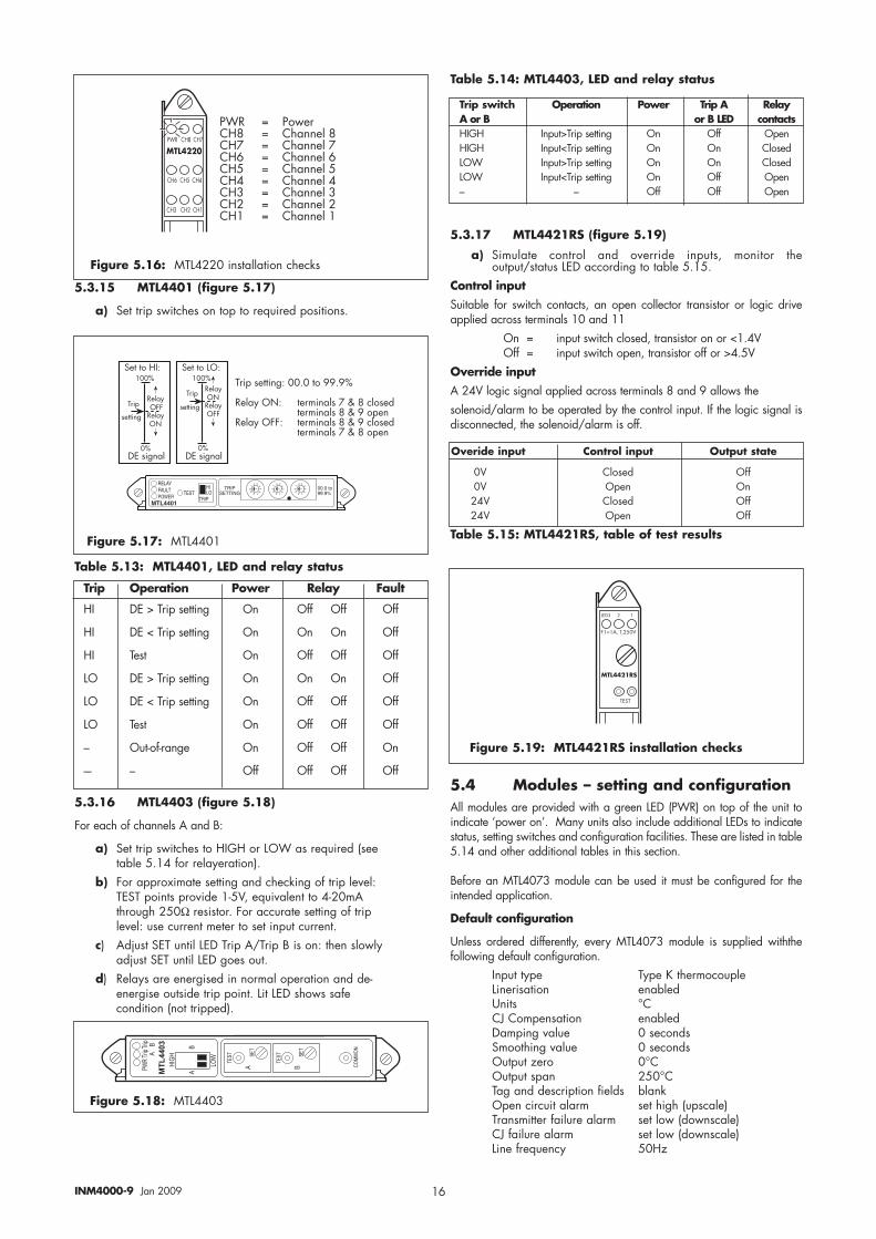
5.3.15 MTL4401 (figure 5.17)
a) Set trip switches on top to required positions.
Table 5.13: MTL4401, LED and relay status
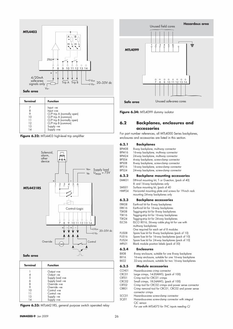
5.3.16 MTL4403 (figure 5.18)
For each of channels A and B:
a) Set trip switches to HIGH or LOW as required (see table 5.14 for relayeration).
b) For approximate setting and checking of trip level: TEST points provide 1-5V, equivalent to 4-20mA through 250Ω resistor. For accurate setting of trip level: use current meter to set input current.
c) Adjust SET until LED Trip A/Trip B is on: then slowly adjust SET until LED goes out.
d) Relays are energised in normal operation and de-energise outside trip point. Lit LED shows safe condition (not tripped).
Table 5.14: MTL4403, LED and relay status
5.3.17 MTL4421RS (figure 5.19)
a) Simulate control and override inputs, monitor theoutput/status LED according to table 5.15.
Control inputSuitable for switch contacts, an open collector transistor or logic driveapplied across terminals 10 and 11
On = input switch closed, transistor on or <1.4V Off = input switch open, transistor off or >4.5V
Override inputA 24V logic signal applied across terminals 8 and 9 allows thesolenoid/alarm to be operated by the control input. If the logic signal isdisconnected, the solenoid/alarm is off.
Table 5.15: MTL4421RS, table of test results
5.4 Modules – setting and configuration All modules are provided with a green LED (PWR) on top of the unit toindicate ‘power on’. Many units also include additional LEDs to indicatestatus, setting switches and configuration facilities. These are listed in table5.14 and other additional tables in this section.
Before an MTL4073 module can be used it must be configured for theintended application.
Default configuration
Unless ordered differently, every MTL4073 module is supplied withthefollowing default configuration.
Input type Type K thermocoupleLinerisation enabledUnits °CCJ Compensation enabledDamping value 0 secondsSmoothing value 0 secondsOutput zero 0°COutput span 250°CTag and description fields blankOpen circuit alarm set high (upscale)Transmitter failure alarm set low (downscale)CJ failure alarm set low (downscale)Line frequency 50Hz
��#���+* ,: ,:
,:� ,:� ,:�
,:� ,:� ,:�
�+* G �����,: G ,�����!�,: G ,�����!�,:� G ,�����!��,:� G ,�����!��,:� G ,�����!��,:� G ,�����!��,:� G ,�����!��,:� G ,�����!��
Figure 5.16: MTL4220 installation checks
��(�(��:2D���H
$��&
��((���
�H
*�!�@855
*�!�@83
16������!
��(�(���8D���H
$��&
��((���
�H
*�!�@83
*�!�@855
16������!
$��&���((���D������(������H
*�!�@�83D (��#���!���I���!���7(��#���!���I����&��
*�!�@�855D (��#���!���I����!���7(��#���!���I���&��
�����8�
'*$%.-%�$#�):*'
#*�##'+�
�+$)
#'+��*##+,;
��
� � ���
�
��
� � ���
�
��
� � ���
�
��<��& ��<�=
Figure 5.17: MTL4401
Trip Operation Power Relay Fault
HI DE > Trip setting On Off Off Off
HI DE < Trip setting On On On Off
HI Test On Off Off Off
LO DE > Trip setting On On On Off
LO DE < Trip setting On Off Off Off
LO Test On Off Off Off
– Out-of-range On Off Off On
-– – Off Off Off Off
��66
�3
'( )*+
)� �> ,
� �> �
��'
,�
�%�� �%
�,
�%�� �%
�� ?�
��
�-
Figure 5.18: MTL4403
Trip switch Operation Power Trip A RelayA or B or B LED contactsHIGH Input>Trip setting On Off OpenHIGH Input<Trip setting On On ClosedLOW Input>Trip setting On On ClosedLOW Input<Trip setting On Off Open– – Off Off Open
Overide input Control input Output state
0V Closed Off0V Open On
24V Closed Off24V Open Off
��#���
�+*
�61� � �
5�G�)J�$J���A
$6�$
Figure 5.19: MTL4421RS installation checks
17INM4000-9 Jan 2009
Configuration (using CNF41-now discontinued)
Configuration is carried out with an MTL611 intrinsically safe hand-heldterminal fitted with a CNF41 configurator interface unit operating version3.1. software (or higher) and a CAB73 cable.Note: to update earlier software, contact MTL or a local representative.
a) Insert the 8-pin plug on cable CAB73 to socket 3 of theCNF41.
b) Insert the 3.5mm jack plug of cable CAB73 into the ‘Config’socket on top of the module.
Initiating configuration
a) Switch on the MTL611 by pressing ‘ON’, the menu will display MTL4073, MTL414, MTL418: if not, press ‘ON’ again.
Note: during configuration, make selections by moving the cursor withthe arrow keys and pressing ‘EXE’ or by pressing the initial letter of theselection (if two selections have the same initial, the cursor will cyclebetween them until stopped by pressing ‘EXE’ ).
b) Press ‘ON’ to deselect the last selection.Checking current configuration
a) Select the M4073 option.b) Select Newtx to open communication with the module;
Working is displayed followed by the module tag name andmodule hardware and software version numbers.
c) Select Upload to read the module configuration into theMTL611 terminal; display shows Loading.
d) Select Configure followed by List to read the currentconfiguration; this is displayed as a list and can be pagedthrough using the up/down arrows.
e) Exit by pressing ‘ON’.
Configuring ‘Online’ or ‘Offline’Module configurations can be changed directly with the module Online.
Alternatively, when a number of modules must be configured with thesame parameters, configuration can be carried out Offline within theconfigurator and Download(ed) later into individual modules.
By default, the configurator operates Online; to take it Offline, selectConfigure, Mode and Offline, followed by pressing ‘EXE’.
Checking current configuration
a) Select the M4073 option.b) Select Newtx to open communication with the module;
Working is displayed followed by the module tag nameand module hardware and software version numbers.
c) Select Upload to read the module configuration into theMTL611 terminal; display shows Loading.
d) Select Configure followed by List to read the currentconfiguration; this is displayed as a list and can be pagedthrough using the up/down arrows.
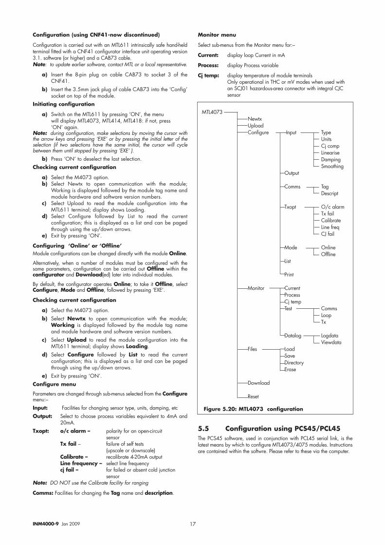
e) Exit by pressing ‘ON’.Configure menu
Parameters are changed through sub-menus selected from the Configuremenu:–Input: Facilities for changing sensor type, units, damping, etcOutput: Select to choose process variables equivalent to 4mA and
20mA.Txopt: o/c alarm – polarity for an open-circuit
sensorTx fail – failure of self tests
(upscale or downscale)Calibrate – recalibrate 4-20mA outputLine frequency – select line frequencycj fail – for failed or absent cold junction
sensorNote: DO NOT use the Calibrate facility for ranging
Comms: Facilities for changing the Tag name and description.
Monitor menu
Select sub-menus from the Monitor menu for:–
Current: display loop Current in mA
Process: display Process variable
Cj temp: display temperature of module terminalsOnly operational in THC or mV modes when used withan SCJ01 hazardous-area connector with integral CJC sensor
MTL4073 Newtx UploadConfigure Input Type
UnitsCj compLineariseDampingSmoothing
Output
Comms TagDescript
Txopt O/c alarmTx failCalibrateLine freqCJ fail
Mode OnlineOffline
List
Monitor CurrentProcessCj tempTest Comms
LoopTx
Datalog LogdataViewdata
Files LoadSaveDirectoryErase
Download
Reset
Figure 5.20: MTL4073 configuration
5.5 Configuration using PCS45/PCL45The PCS45 software, used in conjunction with PCL45 serial link, is thelatest means by which to configure MTL4073/4075 modules. Instructionsare contained within the softwre. Please refer to these via the computer.
$���$�������&(����!
� � � � � � � � �
� � � �� � � �� � ��� ��� ��� ��� ��
�@
A�-
A�C��B��A�7�
, �
��A�����
*����(������K'���74����51
18INM4000-9 Jan 2009
6 TECHNICAL DATA
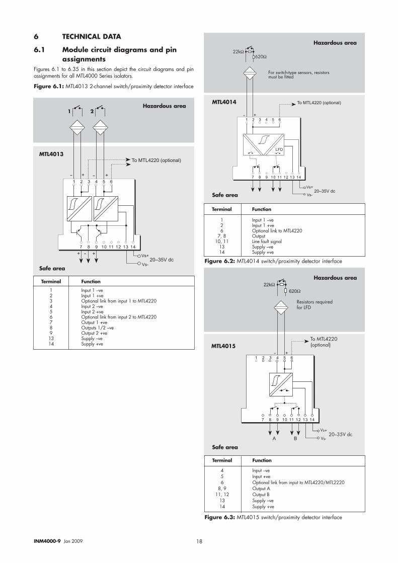
6.1 Module circuit diagrams and pinassignments
Figures 6.1 to 6.35 in this section depict the circuit diagrams and pinassignments for all MTL4000 Series isolators.
Figure 6.1: MTL4013 2-channel switch/proximity detector interface
� � � � � � � � �
� � � �� � � �� � ��� ��� ��� ��� ��
�@
�!@
�!�
����������B�>6���"1C
������#5
���
����
5������(��-(@&���������J������(���#'�(�%��4�((�7
����
Terminal Function
1 Input 1 –ve2 Input 1 +ve6 Optional link to MTL4220
7, 8 Output10, 11 Line fault signal
13 Supply –ve14 Supply +ve
Terminal Function
4 Input –ve5 Input +ve6 Optional link from input to MTL4220/MTL2220
8, 9 Output A11, 12 Output B
13 Supply –ve14 Supply +ve
� � � � � � � � �
� � � �� � � �� � ��� ��� ��� ��� ��
�@ �@
�!@
�!�� �@
����������B�>6���"1C
������#5
� Hazardous area
Hazardous area
Hazardous area
Safe area
Safe area
Safe area
MTL4013
MTL4014
MTL4015
Figure 6.2: MTL4014 switch/proximity detector interface
Figure 6.3: MTL4015 switch/proximity detector interface
Terminal Function
1 Input 1 –ve2 Input 1 +ve3 Optional link from input 1 to MTL42204 Input 2 –ve5 Input 2 +ve6 Optional link from input 2 to MTL42207 Output 1 +ve8 Outputs 1/2 –ve9 Output 2 +ve13 Supply –ve14 Supply +ve
19INM4000-9 Jan 2009
��������
*����(������K'���74����51
$���$��������&(����!
A�CA�B
��B��A�7�
� � � � � � � � �
� � � �� � � �� � ��� ��� ��� ��� ��
�@ �@
� � � � � � � � �
� � � �� � � �� � ��� ��� ��� ��� ��
@
�@
�
�!@
�!�� @������#5
?��6 �18<����7�
$���$��������&(����!C
��!����7J��!��#����(����2�7�<���
Terminal Function
1 Input 1 –ve2 Input 1 +ve3 Optional link from input 1 to MTL42204 Input 2 –ve5 Input 2 +ve6 Optional link from input 2 to MTL4220
7, 8 Output 1A8, 9 Output 2A
10, 11 Output 1B11, 12 Output 2B
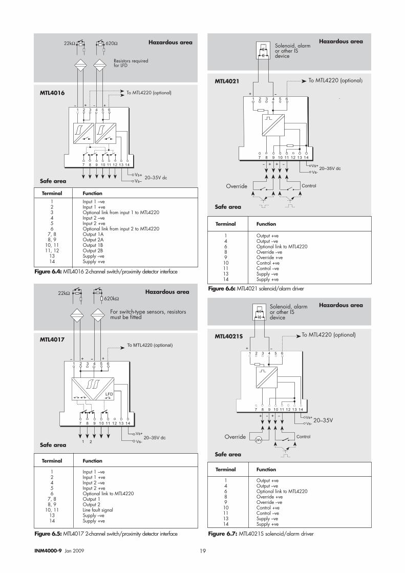
13 Supply –ve14 Supply +ve
5������(��-(@&���������J������(���#'�(�%��4�((�7
���������
� � � � � � � � �
� � � �� � � �� � ��� ��� ��� ��� ��
�!@
�!�
����������B�>6���"1C
������#5
�@ �@
� �
���
� � � � � � � � �
� � � �� � � �� � ��� ��� ��� ��� ��
@
� @
�
�!@
�!�� @��B��A
?��6 �18<����7���
$���$��������&(����!
��!����7J��!��#����(����2�7�<���
Terminal Function
1 Input 1 –ve2 Input 1 +ve4 Input 2 –ve5 Input 2 +ve6 Optional link to MTL4220
7, 8 Output 18, 9 Output 2
10, 11 Line fault signal13 Supply –ve14 Supply +ve
Figure 6.5: MTL4017 2-channel switch/proximity detector interface
Figure 6.4: MTL4016 2-channel switch/proximity detector interface
Figure 6.6: MTL4021 solenoid/alarm driver
Figure 6.7: MTL4021S solenoid/alarm driver
Terminal Function
1 Output +ve4 Output –ve6 Optional link to MTL42208 Override –ve9 Override +ve10 Control +ve11 Control –ve13 Supply –ve14 Supply +ve
Terminal Function
1 Output +ve4 Output –ve6 Optional link to MTL42208 Override +ve9 Override –ve10 Control +ve11 Control –ve13 Supply –ve14 Supply +ve
Safe area
Safe area
Safe area
Safe area
MTL4016
MTL4021
MTL4021SMTL4017
Hazardous area Hazardous area
Hazardous area
Hazardous area
20INM4000-9 Jan 2009
� � � � � � � � �
� � � �� � � �� � ��� ��� ��� ��� ��
@
� @
�
�!@
�!�� @
���
$���$��������&(����!
��!����7J��!��#����(����2�7�<���
� � � � � � � � �
� � � �� � � �� � ��� ��� ��� ��� ��
@
�@
�
�!@
�!�� @������#5
,��(��8<����7�
$���$��������&(����!
��!����7J��!��#����(����2�7�<���
Terminal Function
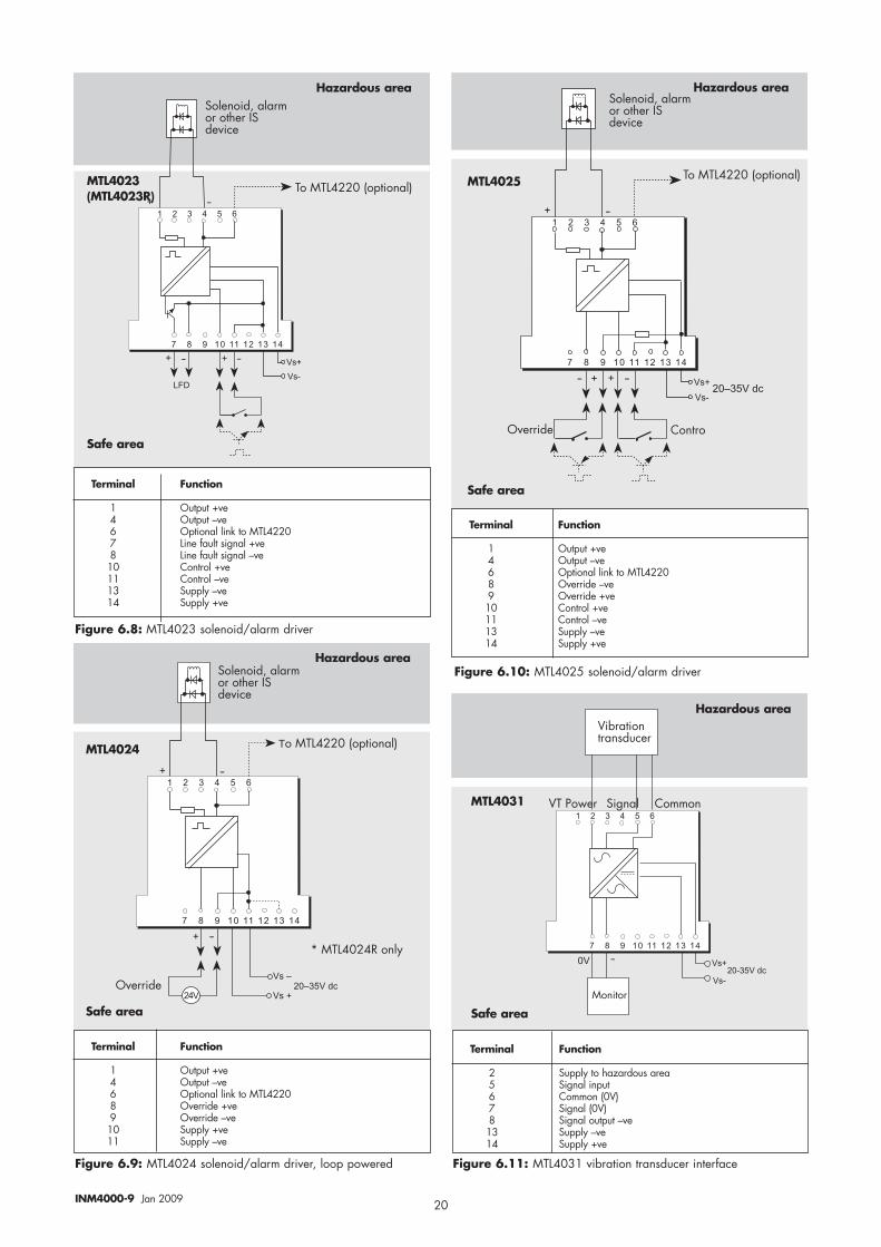
1 Output +ve4 Output –ve6 Optional link to MTL42207 Line fault signal +ve8 Line fault signal –ve10 Control +ve11 Control –ve13 Supply –ve14 Supply +ve
Figure 6.8: MTL4023 solenoid/alarm driver
Figure 6.10: MTL4025 solenoid/alarm driver
Figure 6.9: MTL4024 solenoid/alarm driver, loop powered
� � � � � � � � �
� � � �� � � �� � ��� ��� ��� ��� ��
@
� @
�
8<����7���
�!��
�!��������#5
����$��������&(����!
��!����7J��!��#����(����2�7�<���
F��$�����*���!@
� � � � � � � � �
� � � �� � � �� � ��� ��� ��� ��� ��
�!@
�!�
����(��
�� @��@���#5
A�%��(���(����7'���
A$������ �����! ,�##��
Terminal Function
1 Output +ve4 Output –ve6 Optional link to MTL42208 Override +ve9 Override –ve10 Supply +ve11 Supply –ve
Terminal Function
1 Output +ve4 Output –ve6 Optional link to MTL42208 Override –ve9 Override +ve10 Control +ve11 Control –ve13 Supply –ve14 Supply +ve
Terminal Function
2 Supply to hazardous area5 Signal input6 Common (0V)7 Signal (0V)8 Signal output –ve13 Supply –ve14 Supply +ve
Safe area
Safe area
Hazardous area Hazardous area
Hazardous area
Hazardous area
MTL4023(MTL4023R)
MTL4024
MTL4031
MTL4025
Safe area Safe area
Figure 6.11: MTL4031 vibration transducer interface
21INM4000-9 Jan 2009
� � � � � � � � �
�����������������
�@ �
�!@
�!��������#5
�
� � � �� � � ��
�
�
�
6"(����!!@���'���7�<�!(����&'!��
6"(����!!@���'���7��'����(�&'!��
�-������'����(�&'!��
�-�����<�!(����&'!��
�-������'����(�&'!��
���(��
���"�#�(@�7�(��(��
/��8,
� � � � � � � � �
� � � �� � � �� � ��� ��� ��� ��� ��
))?D
))?D/��8,
�
�
@
�!@�!�
�
�
�
������#5
��"#
�
@
/��8,
F�:��7-��!7���##'����(��
/��8,
� � � � � � � � �
� � � �� � � �� � ��� ��� ��� ��� ��
))?D
))?D
�
�!@�!�
�
�
�
������#5
��"#
�
@
/��8,
F�:��7-��!7���##'����(��
/��8,
� � � � � � � � �
� � � �� � � �� � ��� ��� ��� ��� ��
�
�!@�!�
�������#5
��"#
�
�
))?D
))?D
F:��7-��!7���##'����(��
Terminal Function
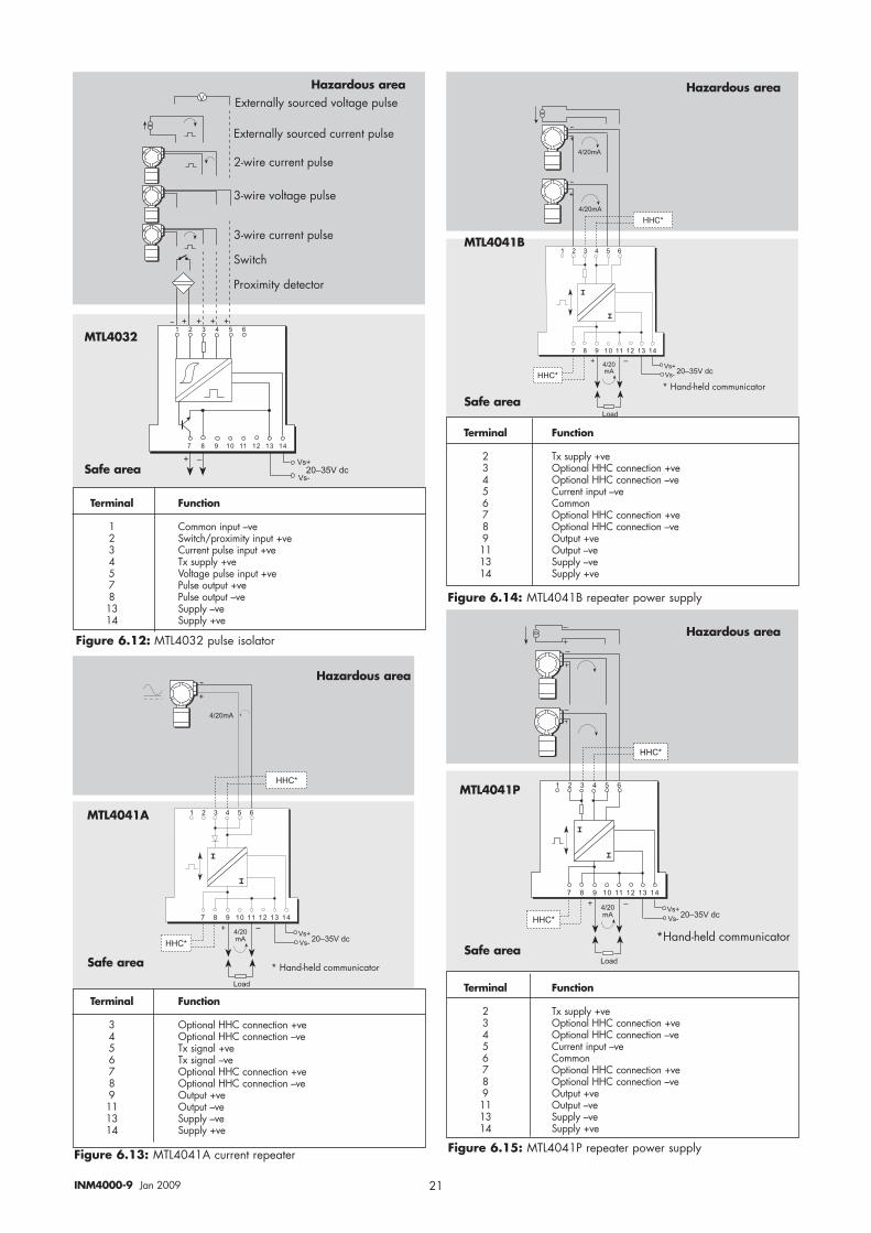
1 Common input –ve2 Switch/proximity input +ve3 Current pulse input +ve4 Tx supply +ve5 Voltage pulse input +ve7 Pulse output +ve8 Pulse output –ve13 Supply –ve14 Supply +ve
Terminal Function
2 Tx supply +ve3 Optional HHC connection +ve4 Optional HHC connection –ve5 Current input –ve6 Common7 Optional HHC connection +ve8 Optional HHC connection –ve9 Output +ve11 Output –ve13 Supply –ve14 Supply +ve
Terminal Function
2 Tx supply +ve3 Optional HHC connection +ve4 Optional HHC connection –ve5 Current input –ve6 Common7 Optional HHC connection +ve8 Optional HHC connection –ve9 Output +ve11 Output –ve13 Supply –ve14 Supply +ve
Figure 6.12: MTL4032 pulse isolator
Figure 6.14: MTL4041B repeater power supply
Figure 6.15: MTL4041P repeater power supplyFigure 6.13: MTL4041A current repeater
Terminal Function
3 Optional HHC connection +ve4 Optional HHC connection –ve5 Tx signal +ve6 Tx signal –ve7 Optional HHC connection +ve8 Optional HHC connection –ve9 Output +ve11 Output –ve13 Supply –ve14 Supply +ve
Safe area
Safe area
Safe areaSafe area
MTL4032
MTL4041B
MTL4041P
MTL4041A
Hazardous area Hazardous area
Hazardous area
Hazardous area
22INM4000-9 Jan 2009
/��8,
� � � � � � � � �
� � � �� � � �� � ��� ��� ��� ��� ��
�
�!@�!�
�������#5
��"#
�
�
/��8,
�0��#)
� � � � � �
::,F
C
A�BA�C
B
%
%
��B��A�7�
C
B
,������7
%
%
::,F
C
B
,�� ,��
CB�0��#)
CB
,������7
CB
::,F,��
::,F,��
� �� �� �� �� ��
�0��#)
� � � � � � � � � � �
���������������������
::,
::,F
�0��#)
C
A�BA�C
B
%
%
��B��A�7�
C
B
�0��#)
C
B
C
B
���7 ��'���C
AB
:��7-��!7��##'����(��
� � � � � �
� �� �� �� �� ��C
A�BA�C
B
��B��A�7�
%
%
2�
C B
Terminal Function
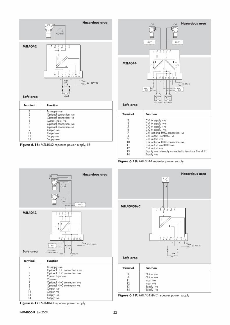
2 Ch1 tx supply +ve3 Ch1 tx supply –ve5 Ch2 tx supply +ve6 Ch2 tx supply –ve7 Ch1 optional HHC connection +ve8 Ch1 output –ve/HHC –ve9 Ch1 output +ve10 Ch2 optional HHC connection +ve11 Ch2 output –ve/HHC –ve12 Ch2 output +ve13 Supply –ve (internally connected to terminals 8 and 11)14 Supply +ve
Terminal Function
3 Output +ve4 Output –ve11 Input –ve12 Input +ve13 Supply –ve14 Supply +ve
Figure 6.16: MTL4042 repeater power supply, IIB
Figure 6.18: MTL4044 repeater power supply
Figure 6.17: MTL4043 repeater power supply
Figure 6.19: MTL4045B/C repeater power supply
Safe area
Safe area
Safe area
Safe area
MTL4042
MTL4043
MTL4045B/C
MTL4044
Hazardous area Hazardous area
Hazardous area Hazardous area
Terminal Function
2 Tx supply +ve3 Optional connection +ve4 Optional connection –ve5 Current input –ve7 Optional connection +ve8 Optional connection –ve9 Output +ve11 Output –ve13 Supply –ve14 Supply +ve
Terminal Function
2 Tx supply +ve3 Optional HHC connection + ve4 Optional HHC connection - ve5 Current input –ve6 Common7 Optional HHC connection +ve8 Optional HHC connection -ve9 Output +ve11 Output --ve13 Supply –ve14 Supply +ve
INM4000-9 Jan 200923
� � � � � � � � �
� � � �� � � �� � ��� ��� ��� ��� ��
�
�!@�!�
�������#5
�
�
� � � �
))?D
))?D
*
/��8,
F:��7-��!7��##'����(��
� � � � � � � � �
�����������������
�����"1
�� � � �� � � ��
� ��!
��
�
�
))?D
))?D
* �0��#)
�0��#)
F�:��7-��!7��##'����(��
� � � � � � � � �
� � � �� � � �� � ��� ��� ��� ��� ��
�
�!@�!�
�������#5
/��8,
��"#
�
�
))?D
F:��7-��!7��##'����(��
�0��#)
� � � � � � � � �
� � � �� � � �� � ��� ��� ��� ��� ��
� @ � @
�@ �@
$���$��������&(����!
�
�
�
�
$���$��������&(����!
5����7�(��(����� 5����7�(��(�����
Terminal Function
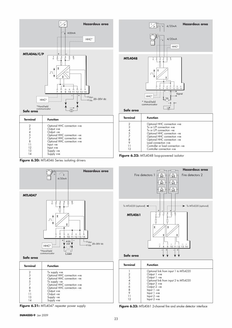
2 Optional HHC connection +ve3 Output +ve4 Output –ve5 Optional HHC connection –ve7 Optional HHC connection –ve8 Optional HHC connection +ve11 Input –ve12 Input +ve13 Supply –ve14 Supply +ve
Terminal Function
2 Optional HHC connection +ve3 Tx or I/P connection +ve4 Tx or I/P connection –ve5 Optional HHC connection –ve7 Optional HHC connection +ve8 Optional HHC connection –ve9 Load connection +ve11 Controller or load connection –ve12 Controller connection +ve
Terminal Function
1 Optional link from input 1 to MTL42202 Output 1 +ve3 Output 1 –ve4 Optional link from input 2 to MTL42205 Output 2 +ve6 Output 2 –ve8 Input 1 –ve9 Input 1 +ve11 Input 2 –ve12 Input 2 +ve
Terminal Function
2 Tx supply +ve3 Optional HHC connection +ve4 Optional HHC connection –ve5 Tx supply –ve7 Optional HHC connection +ve8 Optional HHC connection –ve9 Output +ve11 Output –ve13 Supply –ve14 Supply +ve
Figure 6.22: MTL4048 loop-powered isolator
Figure 6.21: MTL4047 repeater power supply
Figure 6.20: MTL4046 Series isolating drivers
Hazardous area Hazardous area
Hazardous area Hazardous area
Safe area Safe area
Safe areaSafe area
MTL4046/C/PMTL4048
MTL4047
MTL4061
Figure 6.23: MTL4061 2-channel fire and smoke detector interface
24INM4000-9 Jan 2009
,��4��'��(���������(
� � � � � �
� �� �� �� �� ��C
�0��#)A�B
A�C
�.
%
B
��B��A�7�
���7
$��&��&�����!!��(����'(&'(
� � � � � � � � �
� � � �� � � �� � ��� ��� ��� ��� ���
�
�!��
�!��������#5
�
�
�
�
�
A�B
A�C��B��A�7�
��� � � � ��
5��!-��4���'(&'( �51
����
����
5������(�����&'(�J�����(����#'�(�%�4�((�7
���� �����
F
���������������������
��� ��� � ��� �������������
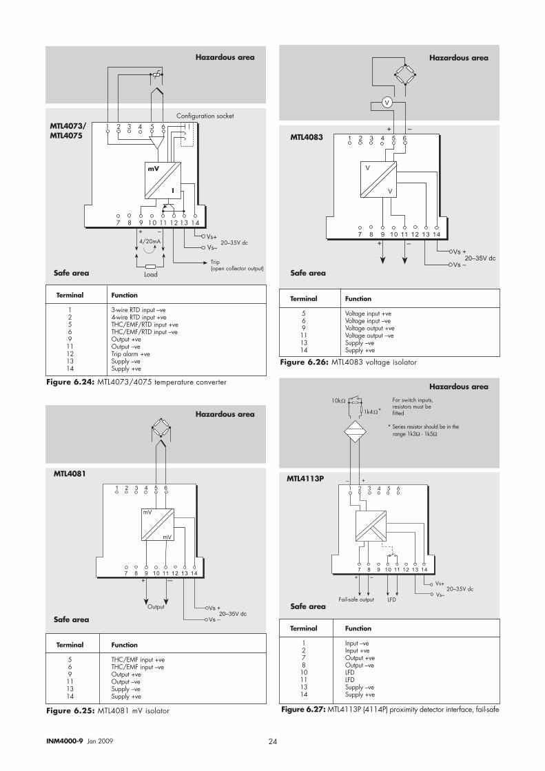
Figure 6.24: MTL4073/4075 temperature converter
Figure 6.26: MTL4083 voltage isolator
Figure 6.27: MTL4113P (4114P) proximity detector interface, fail-safe Figure 6.25: MTL4081 mV isolator
Terminal Function
5 Voltage input +ve6 Voltage input –ve9 Voltage output +ve11 Voltage output –ve13 Supply –ve14 Supply +ve
Terminal Function
1 3-wire RTD input –ve2 4-wire RTD input +ve5 THC/EMF/RTD input +ve6 THC/EMF/RTD input –ve9 Output +ve11 Output –ve12 Trip alarm +ve13 Supply –ve14 Supply +ve
Terminal Function
5 THC/EMF input +ve6 THC/EMF input –ve9 Output +ve11 Output –ve13 Supply –ve14 Supply +ve
Terminal Function
1 Input –ve 2 Input +ve7 Output +ve8 Output –ve10 LFD11 LFD13 Supply –ve14 Supply +ve
Safe area
Safe area Safe area
MTL4073/MTL4075 MTL4083
MTL4113P
* Series resistor should be in therange 1k3Ω - 1k5Ω
Hazardous area Hazardous area
� � � � � � � � �
� � � �� � � �� � ��� ��� ��� ��� ��� �
�!��
�!��������#5
8'(&'(
8�
8�
Safe area
MTL4081
Hazardous area
Hazardous area
25INM4000-9 Jan 2009
� � � � � � � � �
� � � �� � � �� � ��� ��� ��� ��� ��
�!@
�!�� @������#5
*� �1"2
3��-2�����(��
*� �1"2
��������������� ���������� � ���������������� ���
, �
� � � � � � � � � � � � �
� � � �� � � �� � ��� ��� ��� ��� ��
�!@
�!�� @������#5
$��(
6��(��4�'!(������������'�(
) � ) � ) � ) � ) � ) � ) � ) %
$���$������������
��������������� ����� ����� � ���������������� ���
� � � � � � � � �
� � � �� � � �� � � � � ��� ��� ��� ��� ��
�!@
�!�� @������#5
*� �1"2
�
� �
*� �1"2
�
3��-2�����(����
� �
� @
��������������� ���������� � ���������������� ���
����������������������
A�B
A�C��B��A�7�
38
1���7�
$��&
,8�3,
�A�16
B C
Terminal Function
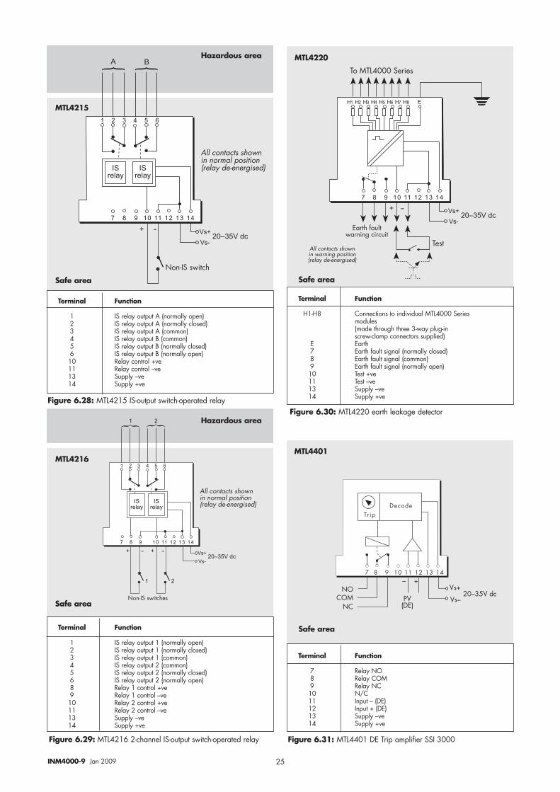
1 IS relay output A (normally open)2 IS relay output A (normally closed)3 IS relay output A (common)4 IS relay output B (common)5 IS relay output B (normally closed)6 IS relay output B (normally open)10 Relay control +ve11 Relay control –ve13 Supply –ve14 Supply +ve
Figure 6.28: MTL4215 IS-output switch-operated relayFigure 6.30: MTL4220 earth leakage detector
Figure 6.29: MTL4216 2-channel IS-output switch-operated relay
Terminal Function
H1-H8 Connections to individual MTL4000 Series modules(made through three 3-way plug-in screw-clamp connectors supplied)
E Earth7 Earth fault signal (normally closed)8 Earth fault signal (common)9 Earth fault signal (normally open)10 Test +ve11 Test –ve13 Supply –ve14 Supply +ve
Terminal Function
7 Relay NO8 Relay COM9 Relay NC10 N/C11 Input – (DE)12 Input + (DE)13 Supply –ve14 Supply +ve
Safe area Safe area
Safe area
Safe area
MTL4215
MTL4220
MTL4216MTL4401
Hazardous area
Hazardous area
Terminal Function
1 IS relay output 1 (normally open)2 IS relay output 1 (normally closed)3 IS relay output 1 (common)4 IS relay output 2 (common)5 IS relay output 2 (normally closed)6 IS relay output 2 (normally open)8 Relay 1 control +ve9 Relay 1 control –ve10 Relay 2 control +ve11 Relay 2 control –ve13 Supply –ve14 Supply +ve
Figure 6.31: MTL4401 DE Trip amplifier SSI 3000
26INM4000-9 Jan 2009
6.2 Backplanes, enclosures andaccessories
For part number references, all MTL4000 Series backplanes, enclosures and accessories are listed in this section.
6.2.1 BackplanesBPM08 8-way backplane, multiway connectorBPM16 16-way backplane, multiway connectorBPM24 24-way backplane, multiway connector BPS04 4-way backplane, screw-clamp connectorBPS08 8-way backplane, screw-clamp connectorBPS16 16-way backplane, screw-clamp connectorBPS24 24-way backplane, screw-clamp connector
6.2.2 Backplane mounting accessoriesDMK01 DIN-rail mounting kit, T- or G-section, (pack of 40)
8- and 16-way backplanes onlySMS01 Surface mounting kit, (pack of 40HMP24 Horizontal mounting plate and screws for 19-inch rack
mounting 24-way backplanes only
6.2.3 Backplane accessoriesERK08 Earth-rail kit for 8-way backplanesERK16 Earth-rail kit for 16-way backplanesTSK08 Tagging-strip kit for 8-way backplanesTSK16 Tagging-strip kit for 16-way backplanesTSK24 Tagging-strip kit for 24-way backplanesELC56 ELCO 8016, 56-way cable plug kit for use with
multiway backplanesOne required for each set of 8 modules
FUS08 Spare fuse kit for 8-way backplanes (pack of 10)FUS16 Spare fuse kit for 16-way backplanes (pack of 10)FUS24 Spare fuse kit for 24-way backplanes (pack of 10)MPL01 Blank module position labels (pack of 50)
6.2.4 EnclosuresBX08 8-way enclosure, suitable for one 8-way backplaneBX16 16-way enclosure, suitable for one 16-way backplaneBX32 32-way enclosure, suitable for two 16-way backplanes
6.2.5 Module accessoriesCCH01 Hazardous-area crimp connectorCRC01 Large crimps, 14-20AWG, (pack of 100)CRT01 Crimp tool for CRC01 crimpsCRC02 Small crimps, 18-24AWG, (pack of 100)CRT02 Crimp tool for CRC02 crimps and power sense connectorCRR01 Crimp removal tool for CRC01, CRC02 and power sense
connector crimpsSCC01 Hazardous-area screw-clamp connectorSCJ01 Hazardous-area screw-clamp connector with integral
CJC sensor.For use with MTL4073 for THC inputs needing CJ
� � � �� � � �� � ��� ��� ��� ��� ��
C
A�BA�C
B
��B��A�7�
, �
)) � �
��
$��&�) $��&�
A�B
�0��#)��4�-����
�����!����!@
� � � � � � � � �
� � � �� � � �� � ��� ��� ��� ��� ��
�9�'��7�4��!7������
9�'��7���4�-����������
�
� � � � � �
� �� �� �� �� ��
C B
�'&&!@�!��79#�"�G��A
C -
A�-
A�CC -
��B��A�7�
,��(��!8<����7���A
,��(��!B�����
��!����7J�!��#J�(���7�<���
A�-
A�C
Terminal Function
7 Input –ve8 Input +ve9 O/P trip A (normally open)10 O/P trip A (common)11 O/P trip B (normally open)12 O/P trip B (common)13 Supply –ve14 Supply +ve
Terminal Function
1 Output +ve4 Output –ve5 Supply load +ve6 Supply load –ve8 Override +ve9 Override –ve10 Control +ve11 Control –ve13 Supply –ve14 Supply +ve
Figure 6.32: MTL4403 high-level trip amplifier
Figure 6.34: MTL4099 dummy isolator
Figure 6.33: MTL4421RS, general purpose switch operated relay
Safe area
Safe area
MTL4403
MTL4099
Hazardous area
Safe area
MTL4421RS
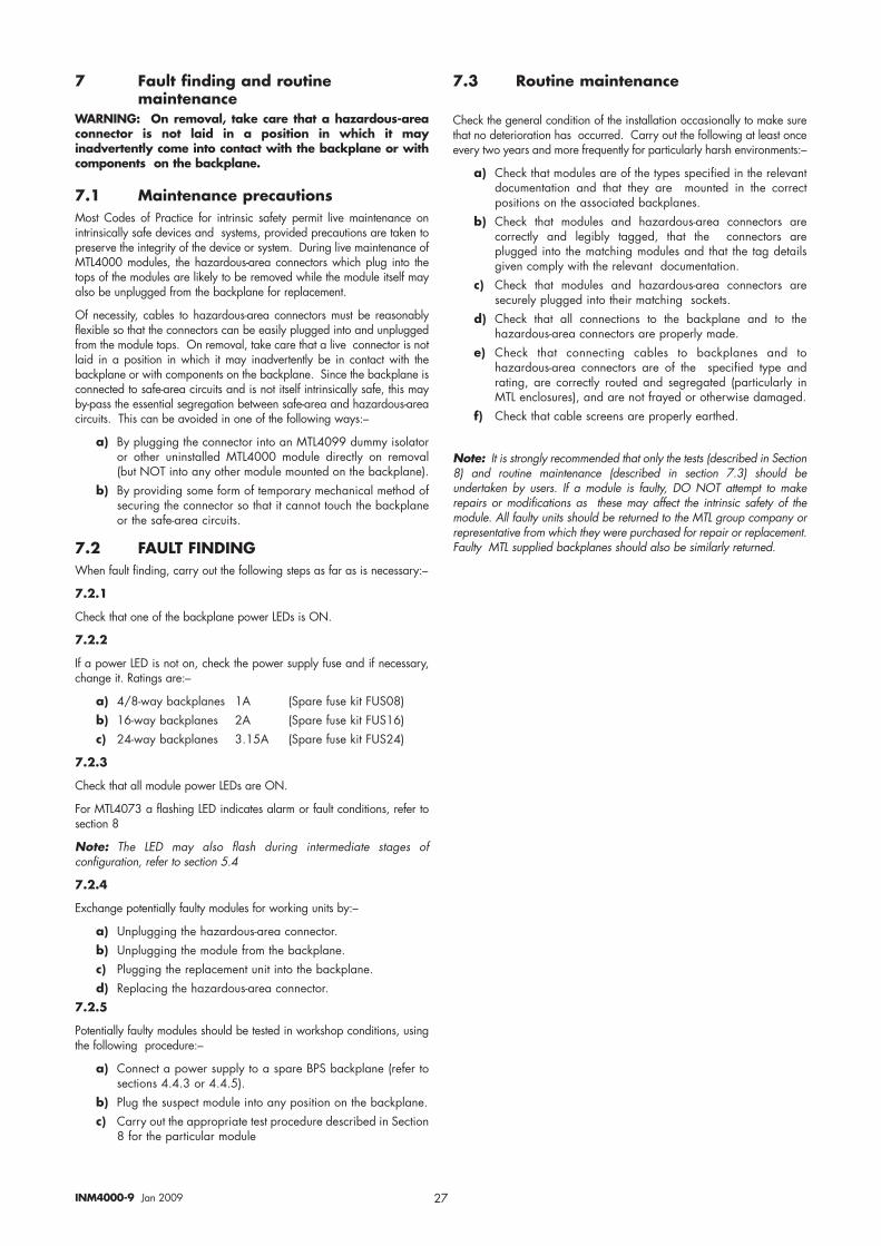
27INM4000-9 Jan 2009
7 Fault finding and routinemaintenance
WARNING: On removal, take care that a hazardous-areaconnector is not laid in a position in which it mayinadvertently come into contact with the backplane or withcomponents on the backplane.
7.1 Maintenance precautions Most Codes of Practice for intrinsic safety permit live maintenance onintrinsically safe devices and systems, provided precautions are taken topreserve the integrity of the device or system. During live maintenance ofMTL4000 modules, the hazardous-area connectors which plug into thetops of the modules are likely to be removed while the module itself mayalso be unplugged from the backplane for replacement.
Of necessity, cables to hazardous-area connectors must be reasonablyflexible so that the connectors can be easily plugged into and unpluggedfrom the module tops. On removal, take care that a live connector is notlaid in a position in which it may inadvertently be in contact with thebackplane or with components on the backplane. Since the backplane isconnected to safe-area circuits and is not itself intrinsically safe, this mayby-pass the essential segregation between safe-area and hazardous-areacircuits. This can be avoided in one of the following ways:–
a) By plugging the connector into an MTL4099 dummy isolatoror other uninstalled MTL4000 module directly on removal(but NOT into any other module mounted on the backplane).
b) By providing some form of temporary mechanical method ofsecuring the connector so that it cannot touch the backplaneor the safe-area circuits.
7.2 FAULT FINDINGWhen fault finding, carry out the following steps as far as is necessary:–
7.2.1
Check that one of the backplane power LEDs is ON.
7.2.2
If a power LED is not on, check the power supply fuse and if necessary,change it. Ratings are:–
a) 4/8-way backplanes 1A (Spare fuse kit FUS08)b) 16-way backplanes 2A (Spare fuse kit FUS16)c) 24-way backplanes 3.15A (Spare fuse kit FUS24)
7.2.3
Check that all module power LEDs are ON.
For MTL4073 a flashing LED indicates alarm or fault conditions, refer tosection 8
Note: The LED may also flash during intermediate stages ofconfiguration, refer to section 5.4
7.2.4
Exchange potentially faulty modules for working units by:–
a) Unplugging the hazardous-area connector.b) Unplugging the module from the backplane.c) Plugging the replacement unit into the backplane.d) Replacing the hazardous-area connector.
7.2.5
Potentially faulty modules should be tested in workshop conditions, usingthe following procedure:–
a) Connect a power supply to a spare BPS backplane (refer tosections 4.4.3 or 4.4.5).
b) Plug the suspect module into any position on the backplane.c) Carry out the appropriate test procedure described in Section
8 for the particular module
7.3 Routine maintenance
Check the general condition of the installation occasionally to make surethat no deterioration has occurred. Carry out the following at least onceevery two years and more frequently for particularly harsh environments:–
a) Check that modules are of the types specified in the relevantdocumentation and that they are mounted in the correctpositions on the associated backplanes.
b) Check that modules and hazardous-area connectors arecorrectly and legibly tagged, that the connectors areplugged into the matching modules and that the tag detailsgiven comply with the relevant documentation.
c) Check that modules and hazardous-area connectors aresecurely plugged into their matching sockets.
d) Check that all connections to the backplane and to thehazardous-area connectors are properly made.
e) Check that connecting cables to backplanes and tohazardous-area connectors are of the specified type andrating, are correctly routed and segregated (particularly inMTL enclosures), and are not frayed or otherwise damaged.
f) Check that cable screens are properly earthed.
Note: It is strongly recommended that only the tests (described in Section8) and routine maintenance (described in section 7.3) should beundertaken by users. If a module is faulty, DO NOT attempt to makerepairs or modifications as these may affect the intrinsic safety of themodule. All faulty units should be returned to the MTL group company orrepresentative from which they were purchased for repair or replacement.Faulty MTL supplied backplanes should also be similarly returned.
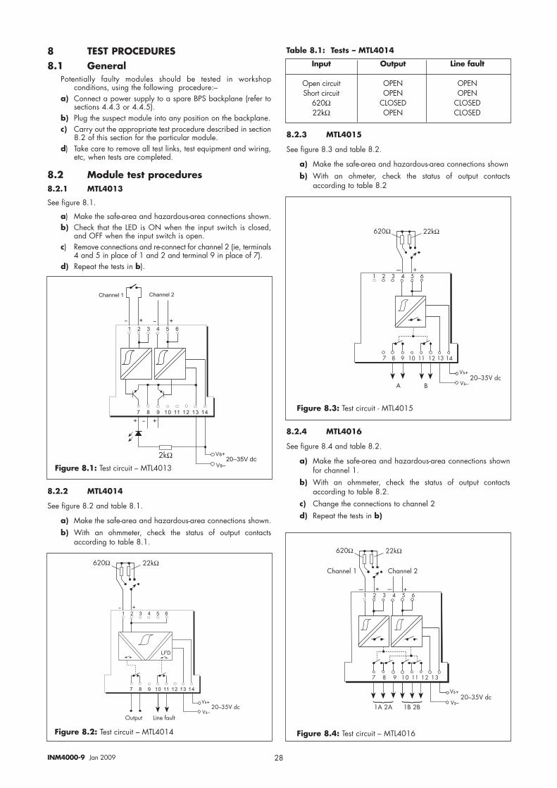
28INM4000-9 Jan 2009
8 TEST PROCEDURES8.1 General
Potentially faulty modules should be tested in workshopconditions, using the following procedure:–
a) Connect a power supply to a spare BPS backplane (refer tosections 4.4.3 or 4.4.5).
b) Plug the suspect module into any position on the backplane.c) Carry out the appropriate test procedure described in section
8.2 of this section for the particular module.d) Take care to remove all test links, test equipment and wiring,
etc, when tests are completed.
8.2 Module test procedures8.2.1 MTL4013
See figure 8.1.
a) Make the safe-area and hazardous-area connections shown.b) Check that the LED is ON when the input switch is closed,
and OFF when the input switch is open.c) Remove connections and re-connect for channel 2 (ie, terminals
4 and 5 in place of 1 and 2 and terminal 9 in place of 7).d) Repeat the tests in b).
8.2.2 MTL4014
See figure 8.2 and table 8.1.
a) Make the safe-area and hazardous-area connections shown.b) With an ohmmeter, check the status of output contacts
according to table 8.1.
Table 8.1: Tests – MTL4014
8.2.3 MTL4015
See figure 8.3 and table 8.2.
a) Make the safe-area and hazardous-area connections shownb) With an ohmeter, check the status of output contacts
according to table 8.2
8.2.4 MTL4016
See figure 8.4 and table 8.2.
a) Make the safe-area and hazardous-area connections shownfor channel 1.
b) With an ohmmeter, check the status of output contactsaccording to table 8.2.
c) Change the connections to channel 2d) Repeat the tests in b)
� � � � � � � � �
� � � �� � � �� � ��� ��� ��� ��� ��
�@ �@
�!�
�!�
� �@
������#5
?3"���1�� ?3"���1��
���
� � � � � � � � �
� � � �� � � �� � ��� ��� ��� ��� ��
�@
A�B
A�C��B��A�7�
���
�����4�'!(8'(&'(
��������
Input Output Line fault
Open circuit OPEN OPENShort circuit OPEN OPEN
620Ω CLOSED CLOSED22kΩ OPEN CLOSED
CB
A�B
A�C��B��A�7�
)
��������
����������� ������������
���������������������
Figure 8.3: Test circuit - MTL4015
Figure 8.1: Test circuit – MTL4013
Figure 8.2: Test circuit – MTL4014
� � � � � � � � � � �
����� ���������������
CB CB
A�B
A�C��B��A�7�
�)��) � ��
,�����!�� ,�����!��
��������
Figure 8.4: Test circuit – MTL4016
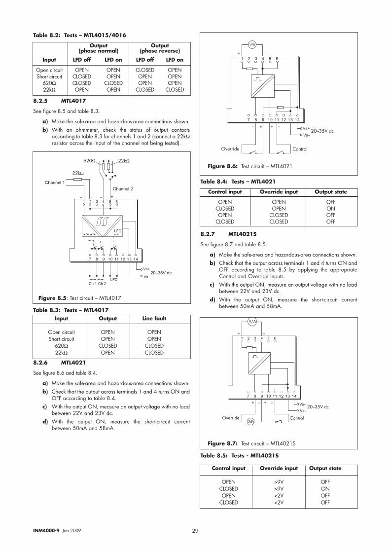
29INM4000-9 Jan 2009
Table 8.2: Tests – MTL4015/4016
8.2.5 MTL4017
See figure 8.5 and table 8.3.
a) Make the safe-area and hazardous-area connections shown.b) With an ohmmeter, check the status of output contacts
according to table 8.3 for channels 1 and 2 (connect a 22kΩresistor across the input of the channel not being tested).
Table 8.3: Tests – MTL4017
8.2.6 MTL4021
See figure 8.6 and table 8.4.
a) Make the safe-area and hazardous-area connections shown.b) Check that the output across terminals 1 and 4 turns ON and
OFF according to table 8.4.c) With the output ON, measure an output voltage with no load
between 22V and 23V dc.d) With the output ON, measure the short-circuit current
between 50mA and 58mA.
Table 8.4: Tests – MTL4021
8.2.7 MTL4021S
See figure 8.7 and table 8.5.
a) Make the safe-area and hazardous-area connections shown.b) Check that the output across terminals 1 and 4 turns ON and
OFF according to table 8.5 by applying the appropriateControl and Override inputs.
c) With the output ON, measure an output voltage with no loadbetween 22V and 23V dc.
d) With the output ON, measure the short-circuit currentbetween 50mA and 58mA.
Table 8.5: Tests - MTL4021S
Output Output(phase normal) (phase reverse)
Input LFD off LFD on LFD off LFD on
Open circuit OPEN OPEN CLOSED OPENShort circuit CLOSED OPEN OPEN OPEN
620Ω CLOSED CLOSED OPEN OPEN22kΩ OPEN OPEN CLOSED CLOSED
� � � � � � � � �
� � � �� � � �� � ��� ��� ��� ��� ��
�!�
�!�������#5
�@ �@
?3��
���
?3"���1��?3"���1��
?3�����E E
��������
����
Figure 8.5: Test circuit – MTL4017
Input Output Line fault
Open circuit OPEN OPENShort circuit OPEN OPEN
620Ω CLOSED CLOSED22kΩ OPEN CLOSED
� � � � � � � � �
� � � �� � � �� � ��� ��� ��� ��� ��
@
�@
�
�!�
�!�� @��B��A�7�
,��(��!8<����7�
�/,
Figure 8.6: Test circuit – MTL4021
Control input Override input Output state
OPEN OPEN OFFCLOSED OPEN ONOPEN CLOSED OFF
CLOSED CLOSED OFF
� � � � � � � � �
� � � �� � � �� � ��� ��� ��� ��� ��
@
� @
�
�!�
�!�� @��B��A�7�
,��(��!8<����7���A
A0)
Figure 8.7: Test circuit – MTL4021S
Control input Override input Output state
OPEN >9V OFFCLOSED >9V ONOPEN <2V OFF
CLOSED <2V OFF
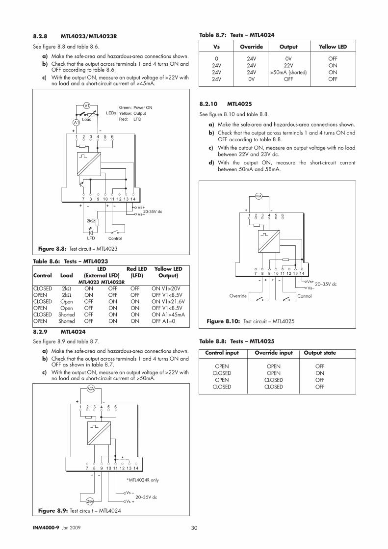
30INM4000-9 Jan 2009
8.2.8 MTL4023/MTL4023R
See figure 8.8 and table 8.6.
a) Make the safe-area and hazardous-area connections shown.b) Check that the output across terminals 1 and 4 turns ON and
OFF according to table 8.6.c) With the output ON, measure an output voltage of >22V with
no load and a short-circuit current of >45mA.
Table 8.6: Tests – MTL4023
8.2.9 MTL4024
See figure 8.9 and table 8.7.
a) Make the safe-area and hazardous-area connections shown.b) Check that the output across terminals 1 and 4 turns ON and
OFF as shown in table 8.7.c) With the output ON, measure an output voltage of >22V with
no load and a short-circuit current of >50mA.
Table 8.7: Tests – MTL4024
8.2.10 MTL4025
See figure 8.10 and table 8.8.
a) Make the safe-area and hazardous-area connections shown.b) Check that the output across terminals 1 and 4 turns ON and
OFF according to table 8.8.c) With the output ON, measure an output voltage with no load
between 22V and 23V dc.d) With the output ON, measure the short-circuit current
between 50mA and 58mA.
Table 8.8: Tests – MTL4025
� � � � � � � � �
� � � �� � � �� � ��� ��� ��� ��� ��
@
� @
�
�!�
�!�� @
���
��
,���"#
�%�!+ ���7 ��� ��-.�11��7 �$6>$6(�#7 ���
�A�
?��6 �1
��@���#5
Figure 8.8: Test circuit – MTL4023
LED Red LED Yellow LEDControl Load (External LFD) (LFD) Output)
MTL4023 MTL4023RCLOSED 2kΩ ON OFF OFF ON V1>20VOPEN 2kΩ ON OFF OFF OFF V1<8.5VCLOSED Open OFF ON ON ON V1>21.6VOPEN Open OFF ON ON OFF V1<8.5VCLOSED Shorted OFF ON ON ON A1>45mAOPEN Shorted OFF ON ON OFF A1=0
� � � � � � � � �
� � � �� � � �� � ��� ��� ��� ��� ��
@
� @
�
��
A��B
A��C��B��A�7�
�/,
F�$�����*���!@
F
Vs Override Output Yellow LED
0 24V 0V OFF24V 24V 22V ON24V 24V >50mA (shorted) ON24V 0V OFF OFF
� � � � � � � � �
� � � �� � � �� � ��� ��� ��� ��� ��
@
�@
�
�!�
�!�� @��B��A�7�
,��(��!8<����7�
�/,
Figure 8.10: Test circuit – MTL4025
Control input Override input Output state
OPEN OPEN OFFCLOSED OPEN ONOPEN CLOSED OFF
CLOSED CLOSED OFF
Figure 8.9: Test circuit – MTL4024
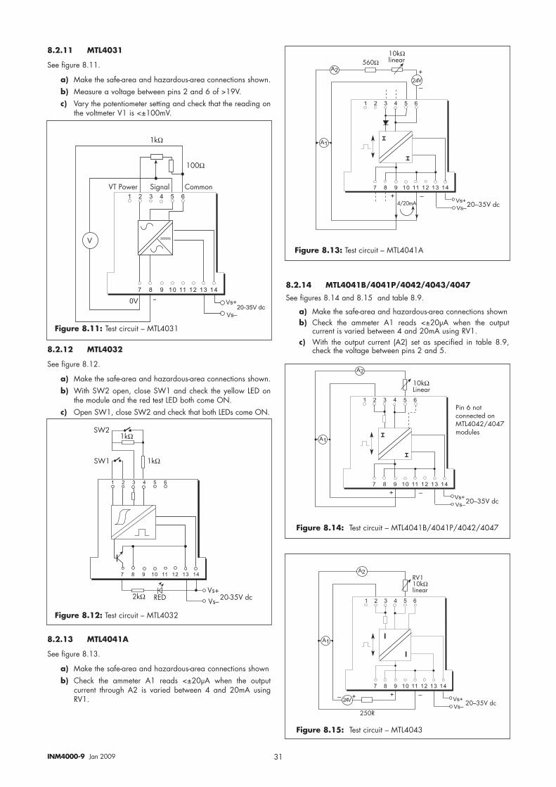
31INM4000-9 Jan 2009
8.2.14 MTL4041B/4041P/4042/4043/4047
See figures 8.14 and 8.15 and table 8.9.
a) Make the safe-area and hazardous-area connections shownb) Check the ammeter A1 reads <±20µA when the output
current is varied between 4 and 20mA using RV1.c) With the output current (A2) set as specified in table 8.9,
check the voltage between pins 2 and 5.
� � � � � � � � �
� � � �� � � �� � ��� ��� ��� ��� ��
����!�����
�
�!��!�
�
�
�
��B��A�7�
,�
,�
����
��A�
�
�0��#)
� � � � � � � � �
� � � �� � � �� � ��� ��� ��� ��� ��
����������
�
�!��!�
�
�
�
��B��A�7�
,�
,�
��������(������(�7����$�����0���#�7'!��
Figure 8.15: Test circuit – MTL4043
Figure 8.14: Test circuit – MTL4041B/4041P/4042/4047
8.2.11 MTL4031
See figure 8.11.
a) Make the safe-area and hazardous-area connections shown.b) Measure a voltage between pins 2 and 6 of >19V.c) Vary the potentiometer setting and check that the reading on
the voltmeter V1 is <±100mV.
8.2.12 MTL4032
See figure 8.12.
a) Make the safe-area and hazardous-area connections shown.b) With SW2 open, close SW1 and check the yellow LED on
the module and the red test LED both come ON.c) Open SW1, close SW2 and check that both LEDs come ON.
8.2.13 MTL4041A
See figure 8.13.
a) Make the safe-area and hazardous-area connections shownb) Check the ammeter A1 reads <±20µA when the output
current through A2 is varied between 4 and 20mA usingRV1.
� � � � � � � � �
�����������������
A�B
A�C
���
� � � �� � � ��
����+�
�+�
��-��A�7���� *61
Figure 8.12: Test circuit – MTL4032
Figure 8.13: Test circuit – MTL4041A
� � � � � � � � �
� � � �� � � �� � ��� ��� ��� ��� ��
�
�!��!�
�
9
9
��B��A�7�
,�
����
���*
,�*A�����!�����
� � � � � � � � �
� � � �� � � �� � ��� ��� ��� ��� ��
�!�
�!��� @��@���#5
A$������ �����! ,�##��
�
���
����
Figure 8.11: Test circuit – MTL4031
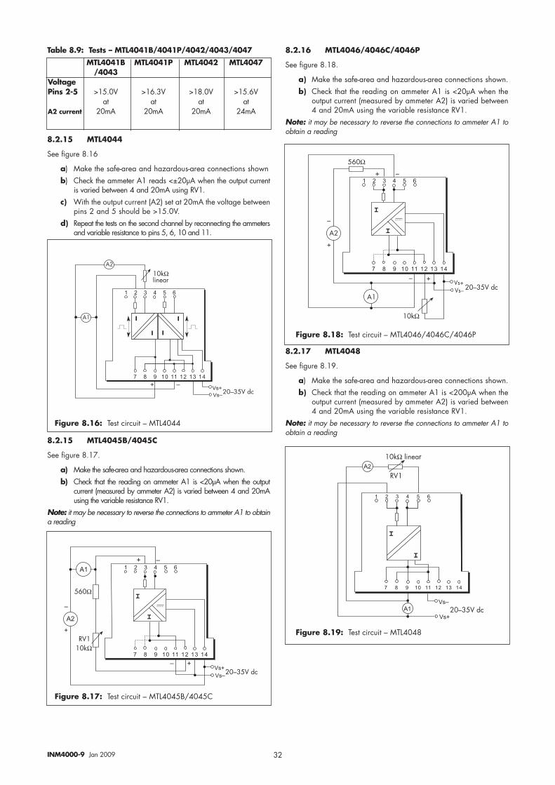
32INM4000-9 Jan 2009
Table 8.9: Tests – MTL4041B/4041P/4042/4043/4047
8.2.15 MTL4044
See figure 8.16
a) Make the safe-area and hazardous-area connections shownb) Check the ammeter A1 reads <±20µA when the output current
is varied between 4 and 20mA using RV1.c) With the output current (A2) set at 20mA the voltage between
pins 2 and 5 should be >15.0V.d) Repeat the tests on the second channel by reconnecting the ammeters
and variable resistance to pins 5, 6, 10 and 11.
8.2.15 MTL4045B/4045C
See figure 8.17.
a) Make the safe-area and hazardous-area connections shown.b) Check that the reading on ammeter A1 is <20µA when the output
current (measured by ammeter A2) is varied between 4 and 20mAusing the variable resistance RV1.
Note: it may be necessary to reverse the connections to ammeter A1 to obtaina reading
8.2.16 MTL4046/4046C/4046P
See figure 8.18.
a) Make the safe-area and hazardous-area connections shown.b) Check that the reading on ammeter A1 is <20µA when the
output current (measured by ammeter A2) is varied between4 and 20mA using the variable resistance RV1.
Note: it may be necessary to reverse the connections to ammeter A1 toobtain a reading
8.2.17 MTL4048
See figure 8.19.
a) Make the safe-area and hazardous-area connections shown.b) Check that the reading on ammeter A1 is <200µA when the
output current (measured by ammeter A2) is varied between4 and 20mA using the variable resistance RV1.
Note: it may be necessary to reverse the connections to ammeter A1 toobtain a reading
MTL4041B MTL4041P MTL4042 MTL4047/4043
VoltagePins 2-5 >15.0V >16.3V >18.0V >15.6V
at at at atA2 current 20mA 20mA 20mA 24mA
� � � � � � � � �
� � � �� � � �� � ��� ��� ��� ��� ���
)�
)�
����!�����
�
�!��!�
��B��A�7�
%
%
%
%
� � � � � � � � �
� � � �� � � �� � ��� ��� ��� ��� ��
C
A�BA�C
B��B��A�7�
�
�
C � � B
)�
����
����
)�
C
B
� � � � � � � � �
������������������ � � �� � � ��
�
�
�!�
�!���B��A�7�
,�
�����!����
*A�
,�
� � � � � � � � �
� � � �� � � �� � ��� ��� ��� ��� ��
�
�!��!�
���B��A�7�
�
�
� � � �,�
,�
�
�
����
����*A�
Figure 8.16: Test circuit – MTL4044
Figure 8.18: Test circuit – MTL4046/4046C/4046P
Figure 8.19: Test circuit – MTL4048
Figure 8.17: Test circuit – MTL4045B/4045C
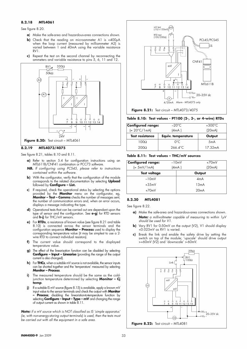
33INM4000-9 Jan 2009
8.2.18 MTL4061
See figure 8.20.
a) Make the safe-area and hazardous-area connections shown.b) Check that the reading on microammeter A1 is <400µA
when the loop current (measured by milliammeter A2) isvaried between 1 and 40mA using the variable resistanceRV1.
c) Repeat the test on the second channel by reconnecting theammeters and variable resistance to pins 5, 6, 11 and 12.
8.2.19 MTL4073/4075
See figure 8.21, tables 8.10 and 8.11.
a) Refer to section 5.4 for configuration instructions using anMTL611B/CNF41 combination or PCC73 software.
NB. If configuring using PCS45, please refer to instructionscontained within the software.
b) With the configurator, verify that the configuration of the modulecorresponds to the related documentation by selecting Uploadfollowed by Configure – List.
c) If required, check the operational status by selecting the optionsprovided by the Monitor menu on the configurator, eg,Monitor – Test – Comms checks the number of messages sent,the number of communication errors and, when an error occurs,displays a message indicating the type.
d) Operational tests that can be carried out are dependant upon thetype of sensor and the configuration. See e-g) for RTD sensorsand h-j) for THC/mV sensors.
e) For RTDs, a resistance of known value (see figure 8.21 and table8.10) is connected across the sensor terminals and theconfiguration sequence Monitor – Process used to display thecorresponding temperature value (it may be simplest to use a 2-wire RTD to connect individual resistors).
f) The current value should correspond to the displayedtemperature value.
g) The effect of the linearisation function can be disabled by selectingConfigure – Input – Linearise (providing the range of the outputcurrent is also changed).
h) For THCs, when a suitable mV source is not available, the sensor inputscan be shorted together and the ‘temperature’ measured by selectingMonitor – Process.
i) The measured temperature should be the same as the cold-junction temperature determined by selecting Monitor – Cjtemp.
j) If a suitable IS mV source (figure 8.15) is available, apply a known mVinput value to the sensor terminals and check the output with Monitor– Process; disabling the linearistion-to-temperature function byselecting Configure – Input – Type – mV and changing the rangeof output current as shown in table 8.11.
Note: if a mV source which is NOT classified as IS ‘simple apparatus’(ie, with non-energy-storing output terminals) is used, then the tests mustbe carried out with all the equipment in a safe area.
Table 8.10: Test values - PT100 (2-, 3-, or 4-wire) RTDs
Table 8.11: Test values – THC/mV sources
8.2.20 MTL4081
See figure 8.22.
a) Make the safe-area and hazardous-area connections shown.Note: a millivoltmeter capable of measuring to within 1µVshould be used for V1.
b) Vary RV1 for 0-50mV on the output (V2), V1 should display<0.025mV as RV1 is varied.
c) Break the link and enable the safety drive by setting theswitch on top of the module; ‘upscale’ should drive output>+60mV (V2) and ‘downscale’ >-60mV.
� � � � � � � � �
� � � �� � � �� � ��� ��� ��� ��� ��
)�
)�
��A
�@
*A�
����
����
C BC B
CB CB
2
2
2
2
� � � � � � � � �
� � � �� � � �� � ��� ��� ��� ��� ��
A��B
A��C��B��A�7�
#A
#A��
����
*A�����
����
C B
��
� � � � � � � � � � �
�����������������������C
A�B
A�CB
��B��A�7�
#A#A�(��(�-��0C���#A
*$1�(��(����0����
�0��#)
�$����
,35��
)
#A
2
�,���0�,���
)!��#�-��$�������!@
Figure 8.20: Test circuit – MTL4061
Figure 8.21: Test circuit – MTL4073/4075
Configured range: –20°C +300°C(= 20°C/1mA) (4mA ) (20mA)
Test resistance Equiv. temperature Output
100Ω 0°C 5mA
200Ω 266.4°C 17.32mA
Figure 8.22: Test circuit – MTL4081
Configured range: –10mV +70mV(= 5mV/1mA) (4mA ) (20mA)
Test voltage Output
–10mV 4mA
+35mV 13mA
+70mV 20mA
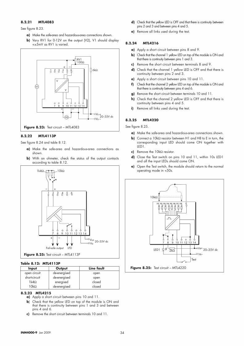
34INM4000-9 Jan 2009
8.2.21 MTL4083
See figure 8.23.
a) Make the safe-area and hazardous-area connections shown.b) Vary RV1 for 0-12V on the output (V2), V1 should display
<±5mV as RV1 is varied.
8.2.22 MTL4113P
See figure 8.24 and table 8.12.
a) Make the safe-area and hazardous-area connections asshown.
b) With an ohmeter, check the status of the output contactsaccording to table 8.12.
Table 8.12: MTL4113P
8.2.23 MTL4215a) Apply a short circuit between pins 10 and 11.b) Check that the yellow LED on top of the module is ON and
that there is continuity between pins 1 and 3 and betweenpins 4 and 6.
c) Remove the short circuit between terminals 10 and 11.
d) Check that the yellow LED is OFF and that there is continuity betweenpins 2 and 3 and between pins 4 and 5.
e) Remove all links used during the test.
8.2.24 MTL4216
a) Apply a short circuit between pins 8 and 9.b) Check that the channel 1 yellow LED on top of the module is ON and
that there is continuity between pins 1 and 3.c) Remove the short circuit between terminals 8 and 9.d) Check that the channel 1 yellow LED is OFF and that there is
continuity between pins 2 and 3.e) Apply a short circuit between pins 10 and 11.f) Check that the channel 2 yellow LED on top of the module is ON and
that there is continuity between pins 4 and 6.g) Remove the short circuit between terminals 10 and 11.h) Check that the channel 2 yellow LED is OFF and that there is
continuity between pins 4 and 5.i) Remove all links used during the test.
8.2.25 MTL4220
See figure 8.25.
a) Make the safe-area and hazardous-area connections shown.b) Connect a 10kΩ resistor between H1 and H8 to E in turn, the
corresponding input LED should come ON together withLED1.
c) Remove the 10kΩ resistor. d) Close the Test switch on pins 10 and 11, within 10s LED1
and all the input LEDs should come ON.e) Open the Test switch, the module should return to the normal
operating mode in <50s.
� � � � � � � � � � �
� � �� � ��� ���������������� �
A��B
A��C��B��A�7�
�
�
��
��
*A�����
�����
� � � � � � � � � � � � �
� � � �� � � �� � ��� ��� ��� ��� ��
�!�
�!� ��B��A�7�
$��(
) � ) � ) � ) � ) � ) � ) � ) %
����61�
����
Figure 8.23: Test circuit – MTL4083
Figure 8.25: Test circuit – MTL4220Input Output Line fault open circuit de-energised openshort-circuit de-energised open
1k4Ω energised closed10kΩ de-energised closed
�51
� � � � � � � � � � �
�����������������������
C
A�-A�C
B��B��A�7�
CB
5��!-��4���'(&'(
��������
Figure 8.25: Test circuit – MTL4113P
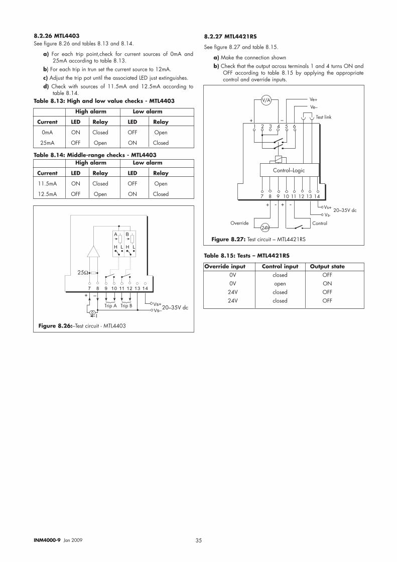
35INM4000-9 Jan 2009
8.2.26 MTL4403See figure 8.26 and tables 8.13 and 8.14.
a) For each trip point,check for current sources of 0mA and25mA according to table 8.13.
b) For each trip in trun set the current source to 12mA.c) Adjust the trip pot until the associated LED just extinguishes.d) Check with sources of 11.5mA and 12.5mA according to
table 8.14.Table 8.13: High and low value checks - MTL4403
Table 8.14: Middle-range checks - MTL4403
High alarm Low alarm
Current LED Relay LED Relay
0mA ON Closed OFF Open
25mA OFF Open ON Closed
High alarm Low alarm
Current LED Relay LED Relay
11.5mA ON Closed OFF Open
12.5mA OFF Open ON Closed
� � � �� � � �� � ��� ��� ��� ��� ��
�
�!��!�
�
��B��A�7�
, �
)) � �
���
$��&�) $��&�
�
Figure 8.26:–Test circuit - MTL4403
8.2.27 MTL4421RS
See figure 8.27 and table 8.15.
a) Make the connection shownb) Check that the output across terminals 1 and 4 turns ON and
OFF according to table 8.15 by applying the appropriatecontrol and override inputs.
Table 8.15: Tests – MTL4421RS
� � � � � �
� �� �� �� �� ��
C B
C -
A�-
A�CC -
��B��A�7�
,��(��!8<����7���A
,��(��!B�����
A�B
$��(�!���
A�CA0)
Figure 8.27: Test circuit – MTL4421RS
Override input Control input Output state0V closed OFF0V open ON24V closed OFF24V closed OFF
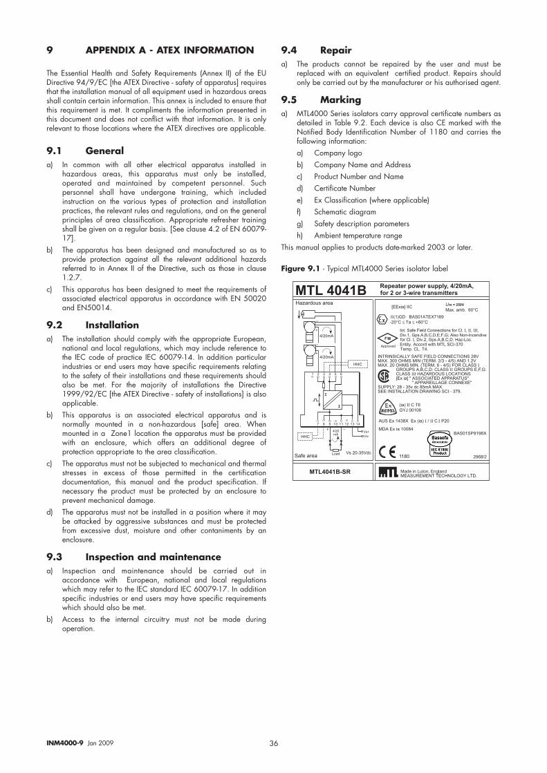
36INM4000-9 Jan 2009
9 APPENDIX A - ATEX INFORMATION
The Essential Health and Safety Requirements (Annex II) of the EUDirective 94/9/EC [the ATEX Directive - safety of apparatus] requiresthat the installation manual of all equipment used in hazardous areasshall contain certain information. This annex is included to ensure thatthis requirement is met. It compliments the information presented inthis document and does not conflict with that information. It is onlyrelevant to those locations where the ATEX directives are applicable.
9.1 Generala) In common with all other electrical apparatus installed in
hazardous areas, this apparatus must only be installed,operated and maintained by competent personnel. Suchpersonnel shall have undergone training, which includedinstruction on the various types of protection and installationpractices, the relevant rules and regulations, and on the generalprinciples of area classification. Appropriate refresher trainingshall be given on a regular basis. [See clause 4.2 of EN 60079-17].
b) The apparatus has been designed and manufactured so as toprovide protection against all the relevant additional hazardsreferred to in Annex II of the Directive, such as those in clause1.2.7.
c) This apparatus has been designed to meet the requirements ofassociated electrical apparatus in accordance with EN 50020and EN50014.
9.2 Installationa) The installation should comply with the appropriate European,
national and local regulations, which may include reference tothe IEC code of practice IEC 60079-14. In addition particularindustries or end users may have specific requirements relatingto the safety of their installations and these requirements shouldalso be met. For the majority of installations the Directive1999/92/EC [the ATEX Directive - safety of installations] is alsoapplicable.
b) This apparatus is an associated electrical apparatus and isnormally mounted in a non-hazardous [safe] area. Whenmounted in a Zone1 location the apparatus must be providedwith an enclosure, which offers an additional degree ofprotection appropriate to the area classification.
c) The apparatus must not be subjected to mechanical and thermalstresses in excess of those permitted in the certificationdocumentation, this manual and the product specification. Ifnecessary the product must be protected by an enclosure toprevent mechanical damage.
d) The apparatus must not be installed in a position where it maybe attacked by aggressive substances and must be protectedfrom excessive dust, moisture and other contaniments by anenclosure.
9.3 Inspection and maintenancea) Inspection and maintenance should be carried out in
accordance with European, national and local regulationswhich may refer to the IEC standard IEC 60079-17. In additionspecific industries or end users may have specific requirementswhich should also be met.
b) Access to the internal circuitry must not be made duringoperation.
9.4 Repair a) The products cannot be repaired by the user and must be
replaced with an equivalent certified product. Repairs shouldonly be carried out by the manufacturer or his authorised agent.
9.5 Markinga) MTL4000 Series isolators carry approval certificate numbers as
detailed in Table 9.2. Each device is also CE marked with theNotified Body Identification Number of 1180 and carries thefollowing information:a) Company logob) Company Name and Addressc) Product Number and Named) Certificate Numbere) Ex Classification (where applicable)f) Schematic diagramg) Safety description parametersh) Ambient temperature range
This manual applies to products date-marked 2003 or later.
��������������������� ������ �� � �!"�#�#$%�� &'
�������� ��� ��������������������������������������������� ���������
(��)��*�++! ��� ��!�"
�)'��,-'��./!
��0�1$&���2���� �3��.�
��4���5��
"�6�5���7��5��
87�9�:8�;
""!
�<,��
�
�<,�
9
9
�<,�
� � � � � � � : � .
�� � ��� � ��� �������������
""!
�
87987�
�
����
�
�
0��1����!� .$%=��.
�����)�����3���)�0��1���<����!���>
&���)�������
�
��
�.�<
��������#
2����>���.3
&�?'���$@7'��2�!�&���A�$B���7�����9+�;����?��+��'���4��A�����!����;����7�4�5�!�'������������
�����C'��;;�5��D��E� ���!+9��4�5�!�'����&�?'��$@7'��2�!�&'�"�69��;'
�,@'�!�'� �'
+� �+��+!���%���A��A+��&�!#���! +#����8 �3'���#" �� +��0 �� '�<��9��<:1���&��'8 �3'��#" �� +�'�0 �� '�.�9��<:1�A#��!���������������������$�#�>����2�!�&F�!��������$�#�>����A�$F���������������!���������"�G��&#����#!� +#�����������������(�)���*�H����#!+� �&��>>��� ��H����������������������������H��>>���+���$��!#���3�H��>>�%F���9��:?��;��:,�� �3'����+�� ���� +#��&��I+�$��!+�9����'
9/!��� �����./!
�@@5�?��
$�
���
Figure 9.1 - Typical MTL4000 Series isolator label
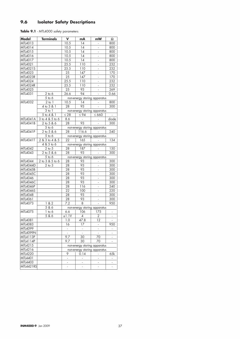
37INM4000-9 Jan 2009
Model Terminals V mA mW ΩΩMTL4013 10.5 14 - 800MTL4014 10.5 14 - 800MTL4015 10.5 14 - 800MTL4016 10.5 14 - 800MTL4017 10.5 14 - 800MTL4021 25.5 110 - 232MTL4021S 25.5 110 - 232MTL4023 25 147 - 170MTL4023R 25 147 - 170MTL4024 25.5 110 - 232MTL4024R 25.5 110 - 232MTL4025 25 93 - 269MTL4031 2 to 6 26.6 94 - 0.66
5 to 6 non-energy storing apparatusMTL4032 2 to 1 10.5 14 - 800
4 to 3 & 1 28 93 - 3003 to 1 non-energy storing apparatus
5 to 4 & 1 ≤ 28 ≤ 94 ≤ 660 -MTL4041A 3 to 4 & 5 to 6 8.6 - - diodeMTL4041B 2 to 5 & 6 28 93 - 300
5 to 6 non-energy storing apparatusMTL4041P 2 to 5 & 6 28 116.6 - 240
5 to 6 non-energy storing apparatusMTL4041T 2 & 3 to 4 & 5 22 165 - 134
4 & 5 to 6 non-energy storing apparatusMTL4042 2 to 5 28 187 - 150MTL4043 2 to 5 & 6 28 93 - 300
5 to 6 non-energy storing apparatusMTL4044 2 to 3 & 5 to 6 28 93 - 300MTL4044D 2 to 3 28 93 - 300MTL4045B 28 93 - 300MTL4045C 28 93 - 300MTL4046 28 93 - 300MTL4046C 28 93 - 300MTL4046P 28 116 - 240MTL4046S 22 100 - 220MTL4048 28 93 - 300MTL4061 28 93 - 300MTL4073 1 & 2 7.2 8 - 950
5 & 6 non-energy storing apparatusMTL4075 1 to 6 6.6 106 175 -
5 & 6 ±1.1V 4 2 -MTL4081 1.0 47.8 12 -MTL4083 16 17 - 950MTL4099 - - - -MTL4099N - - - -MTL4113P 9.7 30 70 -MTL4114P 9.7 30 70 -MTL4215 non-energy storing apparatusMTL4216 non-energy storing apparatusMTL4220 9 0.14 - 65kMTL4401 - - - -MTL4403 - - - -MTL4421RS - - - -
9.6 Isolator Safety Descriptions
Table 9.1 - MTL4000 safety parameters
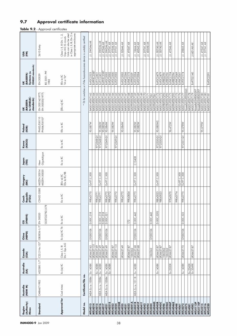
38INM4000-9 Jan 2009
Reg
ion
Aus
tralia
Aus
tralia
Cana
da
Chin
aCI
SCz
ech
Hun
gary
Japan
Kor
eaPo
land
UK
UK
USA
(Aut
hori
ty)
(NSW
M)
(SA
)(C
SA)
(NEP
SI)
(VN
IIVE)
Rep
ublic
(BK
I)(T
IIS)
(KIS
CO)
(KD
B)
(BA
SEEF
A(B
ASE
EFA
) (F
M)
Min
es(F
TZU
)to
CEN
ELEC
-Sy
stem
s (to
stand
ard
s)CE
NEL
EC-s
tand
ard
s)
Stand
ard
C
MRA
67-1
982
AS2
380.
1/7
C22
.2 N
o.15
7G
B383
6-1/
-7EN
500
20C
SN33
038
0M
SZEN
500
14N
ewPN
-83/
E-81
10EN
500
14(1
977)
EN 5
0039
3610
Ent
ityM
SZEN
500
20G
ijyut
ukijy
unPN
-84/
E-81
07EN
500
20(1
977)
GO
ST22
782.
5-78
BS 5
501:
Pt9
1982
Appro
ved f
or
Coa
l min
esEx
(ia)
IIC
Cla
ss I,
II, I
IIEx
(ia)
IIC
T6
Ex ia
IIC
Ex ia
IIC
[EEx
ia] I
ICEx
ia II
CEx
ia II
CEE
x ia
IIC
[EEx
ia] I
ICEE
x ia
IIC
Cla
ss I,
II, I
II D
iv. 1
, 2,
Div.
1 G
ps A
-GEE
x ib
IIC
/IIB
T4 o
r T6*
Grp
s A
-G IS
circ
uits
Uni
ts ca
n al
so b
e sit
ed
in C
lass
I, II
, III,
Div
2 in
appr
opria
te e
nclo
sure
s
Mod
el n
o.Ce
rtific
ate
/file
no.
* T6
for s
witc
hes
or if
the
haza
rdou
s-are
a de
vice
is s
uita
bly
certi
fied
MTL
4013
MD
A E
x ia
100
84Ex
143
8XLR
3663
7-63
GYJ
0010
6D
.00C
.218
99Ex
0770
Ex-9
7.C
.300
95.0
87W
BAS0
1ATE
X716
2Ex
92C
2323
J.I. 5
W3A
4.A
XM
TL4014
LR36
637-
131
BAS0
1ATE
X716
4Ex
993C
2387
MTL
4015
Ex 1
438X
LR36
637-
4999
Ex07
7197
-254
8-Q
1BA
S01A
TEX7
163
Ex91
C24
51M
TL4016
MD
A E
x ia
100
84Ex
143
8XLR
3663
7-49
GYJ
0010
6D
.00C
.218
99Ex
0771
Ex-9
7.C
.300
97-2
548-
Q1
95.0
86W
BAS0
1ATE
X716
3Ex
91C
2451
J.I. 0
W2A
6.A
XM
TL4017
LR36
637-
87D
.00C
.218
95.0
85W
BAS0
1ATE
X716
4Ex
993C
2387
J.I. 4
Y5A
6.A
XM
TL4021
MD
A E
x ia
100
84Ex
143
8XLR
3663
7-49
GYJ
0010
6D
.00C
.221
99Ex
0772
Ex-9
7.C
.300
97-2
549-
Q1
95.0
84W
BAS0
1ATE
X716
5Ex
92C
2002
J.I. 0
W2A
6.A
XM
TL4021S
Ex 1
438X
99Ex
0772
BAS0
1ATE
X716
5Ex
92C
2002
J.I. 5
Y7A
1.A
XM
TL4023
LR36
637-
8795
.083
WBA
S01A
TEX7
166
Ex93
C25
00J.I
. 4Y5
A6.
AX
MTL
4024
LR36
637-
131
99Ex
0772
97-2
549-
Q1
BAS0
1ATE
X716
5Ex
92C
2002
J.I. 5
Y7A
1.A
XM
TL4024R
BAS0
1ATE
X716
5M
TL4025
LR36
637-
4999
Ex07
7295
.084
WBA
S01A
TEX7
165
Ex92
C20
02J.I
. 0Z6
A6.
AX
MTL
4031
BAS0
1ATE
X716
7Ex
94C
2266
MTL
4032
LR36
637-
8717
299
Ex08
34BA
S01A
TEX7
168
Ex94
C21
75J.I
. 4Y5
A7.
AX
MTL
4041A
1065
362
BAS9
9ATE
X702
8Ex
99E2
029
MTL
4041B
MD
A E
x ia
101
18Ex
143
8XLR
3663
7-68
GYJ
0010
6D
.00C
.442
99Ex
0773
Ex-9
7.C
.300
C13
408
95.0
82W
BAS0
1ATE
X716
9Ex
92C
2004
J.I. 1
X6A
4.A
XM
TL4041P
LR36
637-
6895
.082
WBA
S01A
TEX7
169
Ex92
C20
04J.I
. 4X5
A3.
AX
MTL
4041T
BAS0
0ATE
X714
9M
TL4042
BAS0
1ATE
X717
0J.I
. 5Y7
A1.
AX
MTL
4043
BAS0
1ATE
X717
1J.I
. 4D
0A8.
AX
MTL
4044
1065
362
GYJ
0010
6D
.00C
.442
BAS9
9ATE
X706
1M
TL4044D
BAS9
9ATE
X706
1M
TL4045B
Ex 1
438X
LR36
637-
87D
.00C
.220
†98
Ex00
23Ex
-97.
C.3
0097
-255
0-Q
195
.080
W†
BAS0
1ATE
X717
2Ex
93C
2479
J.I. 0
D7A
0.A
XM
TL4045C
LR36
637-
8798
Ex00
2397
-255
0-Q
1BA
S01A
TEX7
172
Ex93
C24
79J.I
. 0D
7A0.
AX
MTL
4046
1065
362
BAS9
8ATE
X729
3Ex
98E2
294
MTL
4046C
1065
362
BAS9
8ATE
X729
3Ex
98E2
294
MTL
4046P
Ex 2
320X
LR36
637-
8797
Ex00
7096
.472
WBA
S01A
TEX7
173
Ex94
C21
94J.I
. 4Y5
A6.
AX
MTL
4046S
BAS9
9ATE
X729
3Ex
98E2
294
MTL
4048
99Ex
0774
BAS0
1ATE
X717
5Ex
94C
2069
MTL
4061
Ex-9
7.C
.300
BAS0
1ATE
X717
6Ex
94C
2041
MTL
4073
Ex 1
438X
LR36
637-
72G
YJ00
106
D.0
0C.2
2299
Ex07
75Ex
-97.
C.3
0097
-255
1-Q
195
.078
WBA
S01A
TEX7
177
Ex93
C21
74J.I
. 2X8
A5.
AX
MTL
4075
Base
efa0
5ATE
X006
5M
TL4081
Ex 2
342X
BAS0
1ATE
X717
8M
TL4083
Ex 3
549X
LR36
637-
87BA
S01A
TEX7
179
Ex97
D21
40J.I
.6D
1A8.
AX
MTL
4113P
Base
efa0
3ATE
X029
7M
TL4114P
Base
efa0
3ATE
X029
7M
TL4215
95.0
79W
BAS0
1ATE
X718
0J.I
. 4Y5
A7.
AX
MTL
4216
BAS0
1ATE
X718
0J.I
. 5Y7
A1.
AX
MTL
4220
BAS0
1ATE
X718
1Ex
95C
2291
9.7 Approval certificate information
Table 9.2 - Approval certificates

39INM4000-9 Jan 2009

Group Internet home page http://www.mtl-inst.com/
Members of The MTL Instruments Group
MTL Instruments Pty Limited1/30 Canvale RoadCanning ValePerth, WA 6155AustraliaTel: +61 (0)8 9455 2994 Fax: +61 (0)8 9455 2805E-mail: [email protected]
MTL Canada Safety Instrumentation#102, 4249 97 StreetEdmonton, AlbertaCanada T6E 5Y7Tel: +1 780 485 3132 Fax: +1 780 485 3122E-mail: [email protected]
MTL Instruments China Co. Ltd.Room 1002A, The GatewayNo 10 Yabao Road, Chaoyang DistrictBeijing 100020ChinaTel: +86 010 8562 5718/5720/5721 Fax: +86 010 8562 5725E-mail: [email protected]
MTL Instruments sarlLes Carrés du Parc10 rue des Rosiéristes69410 Champagne au Mont d’Or FranceTel: +33 (0)4 78 64 98 32 Fax: +33 (0)4 78 35 79 41E-mail: [email protected]
MTL Instruments GmbHAn der Gümpgesbrücke 17D-41564 KaarstGermanyTel: +49 (0)2131 718930 Fax: +49 (0)2131 7189333E-mail: [email protected]
MTL IndiaNo. 36, Nehru StreetOff Old Mahabalipuram RoadSholinganallurChennai - 600 119IndiaTel: + 91 (0)44 24501660/24501857 Fax: + 91 (0)44 24501463E-mail: [email protected]
MTL Italia srlVia Cantù 11I - 20092 Cinisello Balsamo MIItalyTel: +39 (0)2 61802011 Fax: +39 (0)2 61294560E-mail: [email protected]
MTL Instruments KK3rd Floor, Gotanda Masujima Building1-8-13 Higashi-Gotanda, Shinagawa-KuTokyo 141-0022JapanTel: +81 (0)3 5420 1281 Fax: +81 (0)3 5420 2405E-mail: [email protected]
MTL Instruments BVPO Box 55, 6680 AB Bemmelde Houtakker 36, 6681 CW BemmelThe NetherlandsTel: +31 (0)481 450250 Fax: +31 (0)481 450260E-mail: [email protected]
MTL Instruments Pte Limited31 Ubi Road 1#04-01 Aztech BuildingSingapore 408694Tel: +65 6 487 7887 Fax: +65 6 487 7997E-mail: [email protected]
MTL InstrumentsVilla No. 4, Sector 2-17, Street 6PO Box 53234, Abu Dhabi, UAETel: +971 2 446 6840 Fax: +971 2 446 6841E-mail: [email protected]
Measurement Technology LimitedPower Court, Luton, BedfordshireEngland LU1 3JJTel: +44 (0)1582 723633 Fax: +44 (0)1582 422283E-mail: [email protected]
MTL Incorporated4001 W. Sam Houston Parkway N., Suite 150 Houston TX 77043USATel: +1 281 571 8065 Fax: +1 281 571 8069E-mail: [email protected]
Recommended