Series T200 / t300 Tie rod door
Installation Instructions
Part NO. Y009
February 2013
TIE ROD DOOR CUT LENGTH ALTERATIONS
OFFSET JACK SCREW ASSEMBLY
GLAZING AND REGLAZING DOORS
HEADER PREPARATION FOR C.O.C.
CLEARANCE ADJUSTMENTSCLOSER ADJUSTMENTS
OFFSET PIVOT APPLICATIONBUTT HINGE APPLICATION
XIVXIIIXII
IXXXI
TIE ROD CUT LENGTH
PARTS IDENTIFICATION
TIE ROD ASSEMBLY
PUSH/PULL ASSEMBLY
VIVIIVIII
V
IIIIV
PAGE 17
PAGE 16
PAGE 15
PAGE 12-14
PAGE 14
PAGE 15
PAGE 8
PAGE 5-7
PAGE 8
PAGE 9
PAGE 11
PAGE 10
GENERAL NOTES AND GUIDELINES
TABLE OF CONTENTSSECTION
I
PAGE 1
PAGE 2
DOOR PACKAGE IDENTIFICATIONII PAGE 3-4
exterior. 1. Bridging system thermal break with non-thermally broken metal flashing or lintels that are exposed to the inclusive, the list of examples below illustrates conditions under which condensation is likely to occur: Many current installation practices lead to an increase in the possibility of the formation of condensation. Though not all EFCO representative for information on EFCO's Thermal Analysis Services.professional is utilized to perform an analysis of the shop drawings to recommend the best installation methods. Please contacttemperature) are present. When the formation of excessive condensation is a concern, it is highly recommended that a design Condensation will form on any surface when unfavorable conditions (interior temperature and relative humidity and exteriorNOTE: Please reference EFCO's "Understanding Condensation" brochure which can be obtained through your EFCO representative.
Minimizing Condensation
3. Interior relative humidity levels not maintained at recommended levels, see EFCO's "Understanding 2. System exposure to cold air cavities.
4. Inadequate separation between system and surrounding condition at perimeter. Condensation" brochure.
involved. 5. Product combinations during the shop drawing stage that result in bridging thermal breaks of one or all products
SECTION I: GENERAL NOTES AND GUIDELINES
I.
T200/T300 TIE ROD DOOR PAGE 2
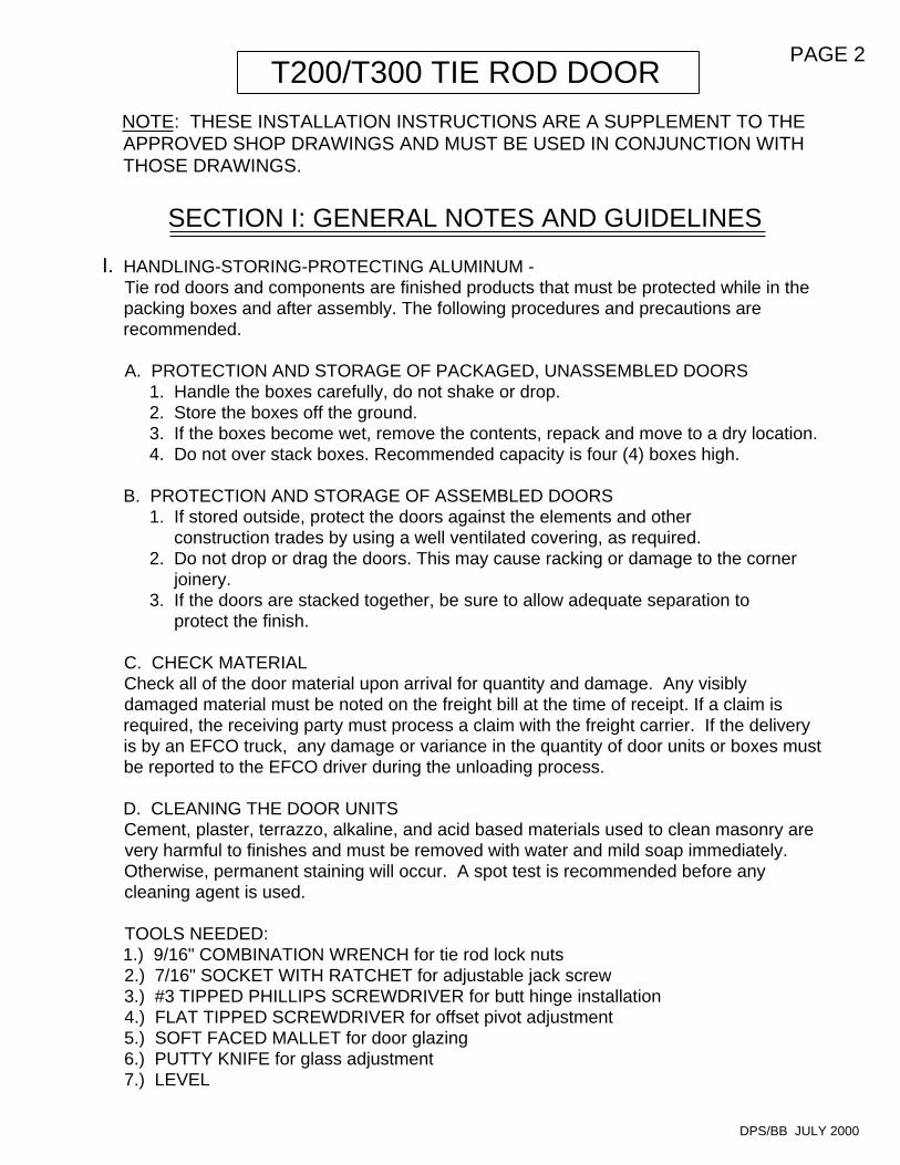
HANDLING-STORING-PROTECTING ALUMINUM -Tie rod doors and components are finished products that must be protected while in the packing boxes and after assembly. The following procedures and precautions are recommended.
A. PROTECTION AND STORAGE OF PACKAGED, UNASSEMBLED DOORS 1. Handle the boxes carefully, do not shake or drop. 2. Store the boxes off the ground. 3. If the boxes become wet, remove the contents, repack and move to a dry location. 4. Do not over stack boxes. Recommended capacity is four (4) boxes high.
B. PROTECTION AND STORAGE OF ASSEMBLED DOORS 1. If stored outside, protect the doors against the elements and other construction trades by using a well ventilated covering, as required. 2. Do not drop or drag the doors. This may cause racking or damage to the corner joinery. 3. If the doors are stacked together, be sure to allow adequate separation to protect the finish.
C. CHECK MATERIALCheck all of the door material upon arrival for quantity and damage. Any visibly damaged material must be noted on the freight bill at the time of receipt. If a claim is required, the receiving party must process a claim with the freight carrier. If the delivery is by an EFCO truck, any damage or variance in the quantity of door units or boxes must be reported to the EFCO driver during the unloading process.
D. CLEANING THE DOOR UNITSCement, plaster, terrazzo, alkaline, and acid based materials used to clean masonry are very harmful to finishes and must be removed with water and mild soap immediately. Otherwise, permanent staining will occur. A spot test is recommended before any cleaning agent is used.
TOOLS NEEDED:1.) 9/16" COMBINATION WRENCH for tie rod lock nuts2.) 7/16" SOCKET WITH RATCHET for adjustable jack screw3.) #3 TIPPED PHILLIPS SCREWDRIVER for butt hinge installation4.) FLAT TIPPED SCREWDRIVER for offset pivot adjustment5.) SOFT FACED MALLET for door glazing6.) PUTTY KNIFE for glass adjustment7.) LEVEL
NOTE: THESE INSTALLATION INSTRUCTIONS ARE A SUPPLEMENT TO THE APPROVED SHOP DRAWINGS AND MUST BE USED IN CONJUNCTION WITH THOSE DRAWINGS.
DPS/BB JULY 2000
SECTION II: DOOR PACKAGE IDENTIFICATION
PAGE 3
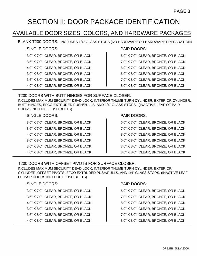
T200 DOORS WITH OFFSET PIVOTS FOR SURFACE CLOSER:INCLUDES MAXIMUM SECURITY DEAD LOCK, INTERIOR THUMB TURN CYLINDER, EXTERIOR CYLINDER, OFFSET PIVOTS, EFCO EXTRUDED PUSH/PULLS, AND 1/4" GLASS STOPS. (INACTIVE LEAF OF PAIR DOORS INCLUDE FLUSH BOLTS)
SINGLE DOORS:
3’0" X 7’0" CLEAR, BRONZE, OR BLACK
3’6" X 7’0" CLEAR, BRONZE, OR BLACK
4’0" X 7’0" CLEAR, BRONZE, OR BLACK
3’0" X 8’0" CLEAR, BRONZE, OR BLACK
3’6" X 8’0" CLEAR, BRONZE, OR BLACK
4’0" X 8’0" CLEAR, BRONZE, OR BLACK
SINGLE DOORS:
3’0" X 7’0" CLEAR, BRONZE, OR BLACK
3’6" X 7’0" CLEAR, BRONZE, OR BLACK
4’0" X 7’0" CLEAR, BRONZE, OR BLACK
3’0" X 8’0" CLEAR, BRONZE, OR BLACK
3’6" X 8’0" CLEAR, BRONZE, OR BLACK
4’0" X 8’0" CLEAR, BRONZE, OR BLACK
T200 DOORS WITH BUTT HINGES FOR SURFACE CLOSER:INCLUDES MAXIMUM SECURITY DEAD LOCK, INTERIOR THUMB TURN CYLINDER, EXTERIOR CYLINDER, BUTT HINGES, EFCO EXTRUDED PUSH/PULLS, AND 1/4" GLASS STOPS. (INACTIVE LEAF OF PAIR DOORS INCLUDE FLUSH BOLTS)
SINGLE DOORS:
3’0" X 7’0" CLEAR, BRONZE, OR BLACK
3’6" X 7’0" CLEAR, BRONZE, OR BLACK
4’0" X 7’0" CLEAR, BRONZE, OR BLACK
3’0" X 8’0" CLEAR, BRONZE, OR BLACK
3’6" X 8’0" CLEAR, BRONZE, OR BLACK
4’0" X 8’0" CLEAR, BRONZE, OR BLACK
BLANK T200 DOORS: INCLUDES 1/4" GLASS STOPS (NO HARDWARE OR HARDWARE PREPARATION)
AVAILABLE DOOR SIZES, COLORS, AND HARDWARE PACKAGES
DPS/BB JULY 2000
PAIR DOORS:
6’0" X 7’0" CLEAR, BRONZE, OR BLACK
7’0" X 7’0" CLEAR, BRONZE, OR BLACK
8’0" X 7’0" CLEAR, BRONZE, OR BLACK
6’0" X 8’0" CLEAR, BRONZE, OR BLACK
7’0" X 8’0" CLEAR, BRONZE, OR BLACK
8’0" X 8’0" CLEAR, BRONZE, OR BLACK
PAIR DOORS:
6’0" X 7’0" CLEAR, BRONZE, OR BLACK
7’0" X 7’0" CLEAR, BRONZE, OR BLACK
8’0" X 7’0" CLEAR, BRONZE, OR BLACK
6’0" X 8’0" CLEAR, BRONZE, OR BLACK
7’0" X 8’0" CLEAR, BRONZE, OR BLACK
8’0" X 8’0" CLEAR, BRONZE, OR BLACK
PAIR DOORS:
6’0" X 7’0" CLEAR, BRONZE, OR BLACK
7’0" X 7’0" CLEAR, BRONZE, OR BLACK
8’0" X 7’0" CLEAR, BRONZE, OR BLACK
6’0" X 8’0" CLEAR, BRONZE, OR BLACK
7’0" X 8’0" CLEAR, BRONZE, OR BLACK
8’0" X 8’0" CLEAR, BRONZE, OR BLACK
SECTION II: DOOR PACKAGE IDENTIFICATION(CONTINUED)
PAGE 4
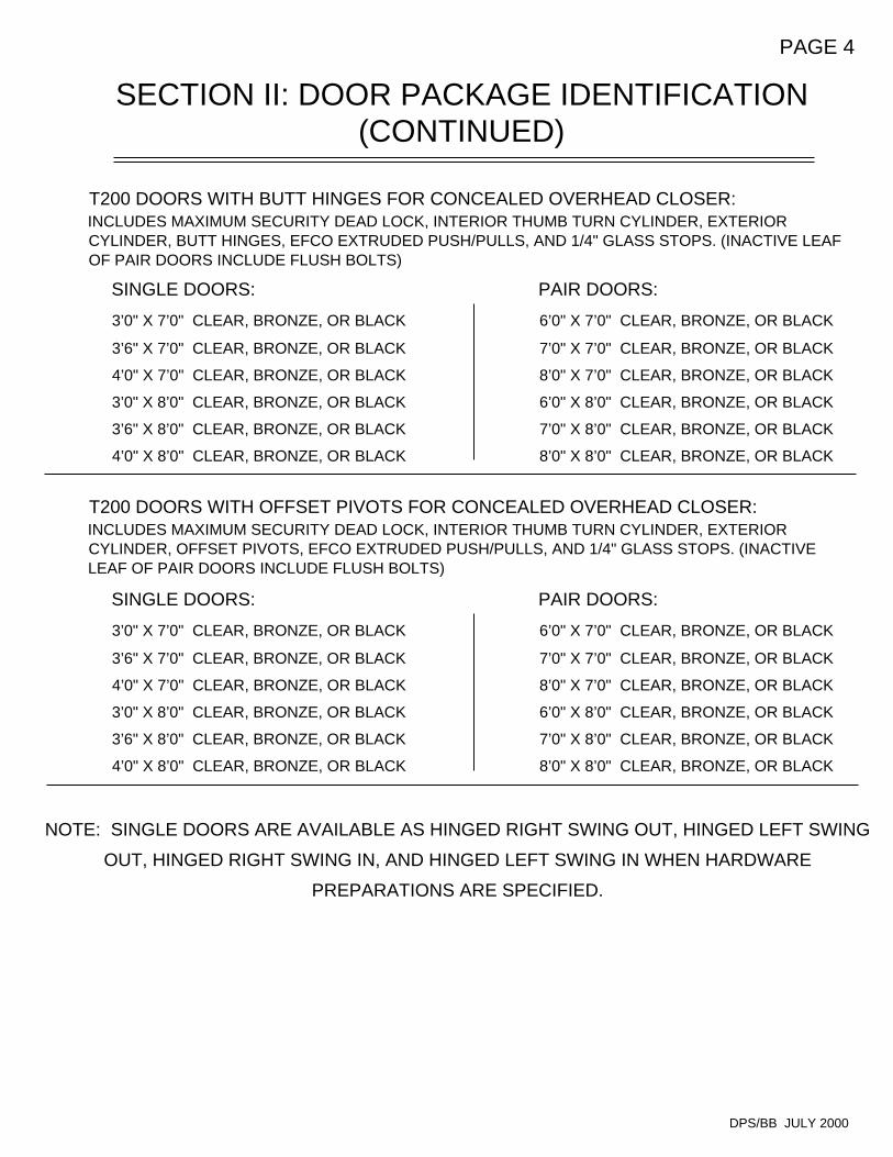
T200 DOORS WITH BUTT HINGES FOR CONCEALED OVERHEAD CLOSER:INCLUDES MAXIMUM SECURITY DEAD LOCK, INTERIOR THUMB TURN CYLINDER, EXTERIOR CYLINDER, BUTT HINGES, EFCO EXTRUDED PUSH/PULLS, AND 1/4" GLASS STOPS. (INACTIVE LEAF OF PAIR DOORS INCLUDE FLUSH BOLTS)
SINGLE DOORS:
3’0" X 7’0" CLEAR, BRONZE, OR BLACK
3’6" X 7’0" CLEAR, BRONZE, OR BLACK
4’0" X 7’0" CLEAR, BRONZE, OR BLACK
3’0" X 8’0" CLEAR, BRONZE, OR BLACK
3’6" X 8’0" CLEAR, BRONZE, OR BLACK
4’0" X 8’0" CLEAR, BRONZE, OR BLACK
NOTE: SINGLE DOORS ARE AVAILABLE AS HINGED RIGHT SWING OUT, HINGED LEFT SWING
OUT, HINGED RIGHT SWING IN, AND HINGED LEFT SWING IN WHEN HARDWARE
PREPARATIONS ARE SPECIFIED.
T200 DOORS WITH OFFSET PIVOTS FOR CONCEALED OVERHEAD CLOSER:INCLUDES MAXIMUM SECURITY DEAD LOCK, INTERIOR THUMB TURN CYLINDER, EXTERIOR CYLINDER, OFFSET PIVOTS, EFCO EXTRUDED PUSH/PULLS, AND 1/4" GLASS STOPS. (INACTIVE LEAF OF PAIR DOORS INCLUDE FLUSH BOLTS)
SINGLE DOORS:
3’0" X 7’0" CLEAR, BRONZE, OR BLACK
3’6" X 7’0" CLEAR, BRONZE, OR BLACK
4’0" X 7’0" CLEAR, BRONZE, OR BLACK
3’0" X 8’0" CLEAR, BRONZE, OR BLACK
3’6" X 8’0" CLEAR, BRONZE, OR BLACK
4’0" X 8’0" CLEAR, BRONZE, OR BLACK
PAIR DOORS:
6’0" X 7’0" CLEAR, BRONZE, OR BLACK
7’0" X 7’0" CLEAR, BRONZE, OR BLACK
8’0" X 7’0" CLEAR, BRONZE, OR BLACK
6’0" X 8’0" CLEAR, BRONZE, OR BLACK
7’0" X 8’0" CLEAR, BRONZE, OR BLACK
8’0" X 8’0" CLEAR, BRONZE, OR BLACK
DPS/BB JULY 2000
SEE SECTION B25 IN THE EFCO PRICE CATALOG FOR AVAILABLE PACKAGE
OPTIONS. INCLUDED OPTIONS ARE:
T300 MEDIUM STILE TIE ROD DOOR
1" GLASS STOPS
7 1/2" BOTTOM RAIL
10" BOTTOM RAIL
PAIR DOORS:
6’0" X 7’0" CLEAR, BRONZE, OR BLACK
7’0" X 7’0" CLEAR, BRONZE, OR BLACK
8’0" X 7’0" CLEAR, BRONZE, OR BLACK
6’0" X 8’0" CLEAR, BRONZE, OR BLACK
7’0" X 8’0" CLEAR, BRONZE, OR BLACK
8’0" X 8’0" CLEAR, BRONZE, OR BLACK
SECTION III: PARTS IDENTIFICATIONPAGE 5
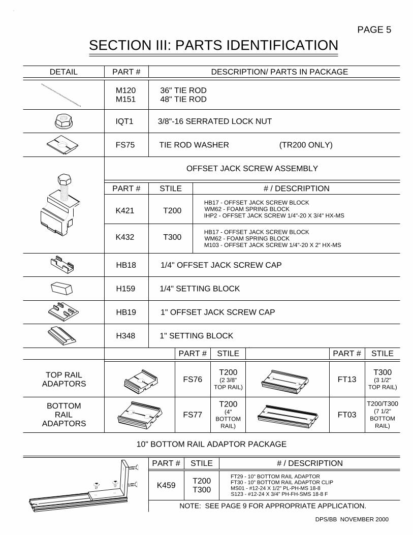
T300(3 1/2"
TOP RAIL)
T200/T300(7 1/2"
BOTTOMRAIL)
H348 1" SETTING BLOCK
H159 1/4" SETTING BLOCK
PART #
10" BOTTOM RAIL ADAPTOR PACKAGE
HB19 1" OFFSET JACK SCREW CAP
HB18 1/4" OFFSET JACK SCREW CAP
K421 T200
K432 T300
BOTTOMRAIL
ADAPTORS
TOP RAILADAPTORS
PART #
NOTE: SEE PAGE 9 FOR APPROPRIATE APPLICATION.
FT29 - 10" BOTTOM RAIL ADAPTORFT30 - 10" BOTTOM RAIL ADAPTOR CLIPMS01 - #12-24 X 1/2" PL-PH-MS 18-8S123 - #12-24 X 3/4" PH-FH-SMS 18-8 F
K459 T200T300
STILE
FS77T200
(4"BOTTOM
RAIL)
DPS/BB NOVEMBER 2000
# / DESCRIPTION
FT03
# / DESCRIPTION
HB17 - OFFSET JACK SCREW BLOCKWM62 - FOAM SPRING BLOCKM103 - OFFSET JACK SCREW 1/4"-20 X 2" HX-MS
HB17 - OFFSET JACK SCREW BLOCKWM62 - FOAM SPRING BLOCKIHP2 - OFFSET JACK SCREW 1/4"-20 X 3/4" HX-MS
T200(2 3/8"
TOP RAIL)
PART #
FS76
STILE
STILE
PART #
FT13
STILE
FS75 TIE ROD WASHER
IQT1 3/8"-16 SERRATED LOCK NUT
M120 36" TIE RODM151 48" TIE ROD
DETAIL PART # DESCRIPTION/ PARTS IN PACKAGE
OFFSET JACK SCREW ASSEMBLY
(TR200 ONLY)
SECTION III: PARTS IDENTIFICATIONPAGE 6
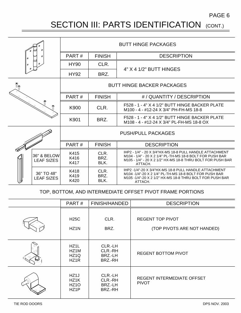
HZ1JHZ1KHZ1OHZ1P
HZ1LHZ1MHZ1QHZ1R
H25C
HZ1N
CLR.
BRZ.
CLR.-LHCLR.-RHBRZ.-LHBRZ.-RH
CLR.-LHCLR.-RHBRZ.-LHBRZ.-RH
REGENT BOTTOM PIVOT
REGENT INTERMEDIATE OFFSET PIVOT
REGENT TOP PIVOT
(TOP PIVOTS ARE NOT HANDED)
IHP2 -1/4"-20 X 3/4"HX-MS 18-8 PULL HANDLE ATTACHMENTM104 -1/4"-20 X 2 1/4" PL-TH-MS 18-8 BOLT FOR PUSH BARM105 -1/4"-20 X 2 1/2" HX-MS 18-8 THRU BOLT FOR PUSH BAR ATTACH.
IHP2 - 1/4" - 20 X 3/4"HX-MS 18-8 PULL HANDLE ATTACHMENTM104 - 1/4" - 20 X 2 1/4" PL-TH-MS 18-8 BOLT FOR PUSH BARM105 - 1/4" - 20 X 2 1/2" HX-MS 18-8 THRU BOLT FOR PUSH BAR ATTACH.
DESCRIPTION
TOP, BOTTOM, AND INTERMEDIATE OFFSET PIVOT FRAME PORTIONS
DESCRIPTION
F528 - 1 - 4" X 4 1/2" BUTT HINGE BACKER PLATEM108 - 4 - #12-24 X 3/4" PL-FH-MS 18-8 OX
# / QUANTITY / DESCRIPTION
F528 - 1 - 4" X 4 1/2" BUTT HINGE BACKER PLATEM100 - 4 - #12-24 X 3/4" PH-FH-MS 18-8K900 CLR.
K901 BRZ.
CLR.BRZ.BLK.
K415K416K417
FINISH/HANDEDPART #
K418K419K420
CLR.BRZ.BLK.
PUSH/PULL PACKAGES
PART # FINISH DESCRIPTION
HY90 CLR.
HY92 BRZ.
BUTT HINGE BACKER PACKAGES
FINISH PART #
BUTT HINGE PACKAGES
PART # FINISH
4" X 4 1/2" BUTT HINGES
36" TO 48"LEAF SIZES
36" & BELOWLEAF SIZES
DPS NOV. 2003TIE ROD DOORS
(CONT.)
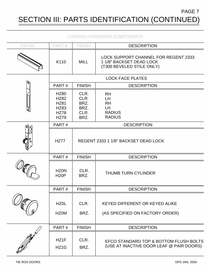
SECTION III: PARTS IDENTIFICATION (CONTINUED)PAGE 7
DESCRIPTION
LOCK SUPPORT CHANNEL FOR REGENT 2333 1 1/8" BACKSET DEAD LOCK(T300 BEVELED STILE ONLY)
LOCK FACE PLATES
K110 MILL
PART # FINISH DESCRIPTION
RHLHRHLHRADIUSRADIUS
HZ80 CLR.HZ82 CLR.HZ81 BRZ.HZ83 BRZ.HZ78 CLR.HZ79 BRZ.
PART # DESCRIPTION
HZ77 REGENT 2333 1 1/8" BACKSET DEAD LOCK
PART #
HZ0N CLR.H20P BRZ.
FINISH DESCRIPTION
THUMB TURN CYLINDER
PART # FINISH DESCRIPTION
KEYED DIFFERENT OR KEYED ALIKE
(AS SPECIFIED ON FACTORY ORDER)
EFCO STANDARD TOP & BOTTOM FLUSH BOLTS(USE AT INACTIVE DOOR LEAF @ PAIR DOORS)
DESCRIPTIONFINISHPART #
HZ0L CLR.
HZ0M BRZ.
HZ1F CLR.
HZ1G BRZ.
TIE ROD DOORS DPS JAN. 2004
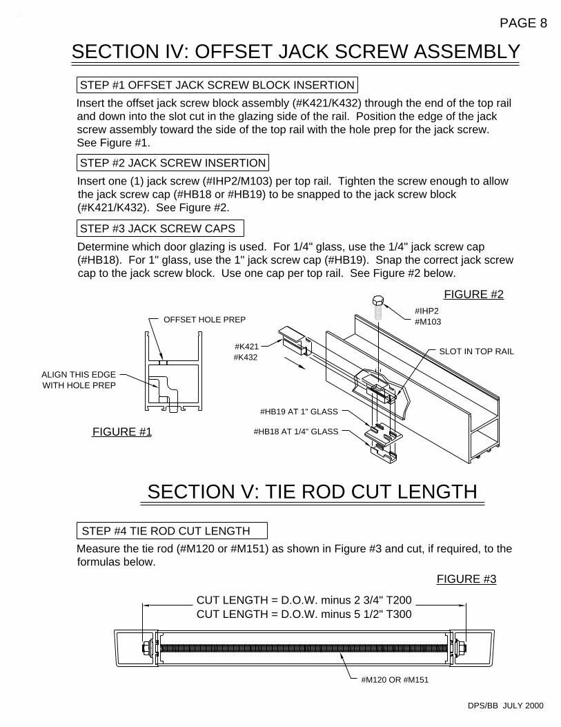
FIGURE #3
SECTION V: TIE ROD CUT LENGTH
STEP #4 TIE ROD CUT LENGTH
FIGURE #1
STEP #3 JACK SCREW CAPS
STEP #2 JACK SCREW INSERTION
FIGURE #2
STEP #1 OFFSET JACK SCREW BLOCK INSERTION
SECTION IV: OFFSET JACK SCREW ASSEMBLY
PAGE 8
SLOT IN TOP RAIL
CUT LENGTH = D.O.W. minus 2 3/4" T200CUT LENGTH = D.O.W. minus 5 1/2" T300
#M120 OR #M151
Measure the tie rod (#M120 or #M151) as shown in Figure #3 and cut, if required, to the formulas below.
Determine which door glazing is used. For 1/4" glass, use the 1/4" jack screw cap (#HB18). For 1" glass, use the 1" jack screw cap (#HB19). Snap the correct jack screw cap to the jack screw block. Use one cap per top rail. See Figure #2 below.
Insert one (1) jack screw (#IHP2/M103) per top rail. Tighten the screw enough to allow the jack screw cap (#HB18 or #HB19) to be snapped to the jack screw block (#K421/K432). See Figure #2.
Insert the offset jack screw block assembly (#K421/K432) through the end of the top rail and down into the slot cut in the glazing side of the rail. Position the edge of the jack screw assembly toward the side of the top rail with the hole prep for the jack screw. See Figure #1.
ALIGN THIS EDGEWITH HOLE PREP
#HB18 AT 1/4" GLASS
#HB19 AT 1" GLASS
#K421#K432
OFFSET HOLE PREP
DPS/BB JULY 2000
#IHP2#M103
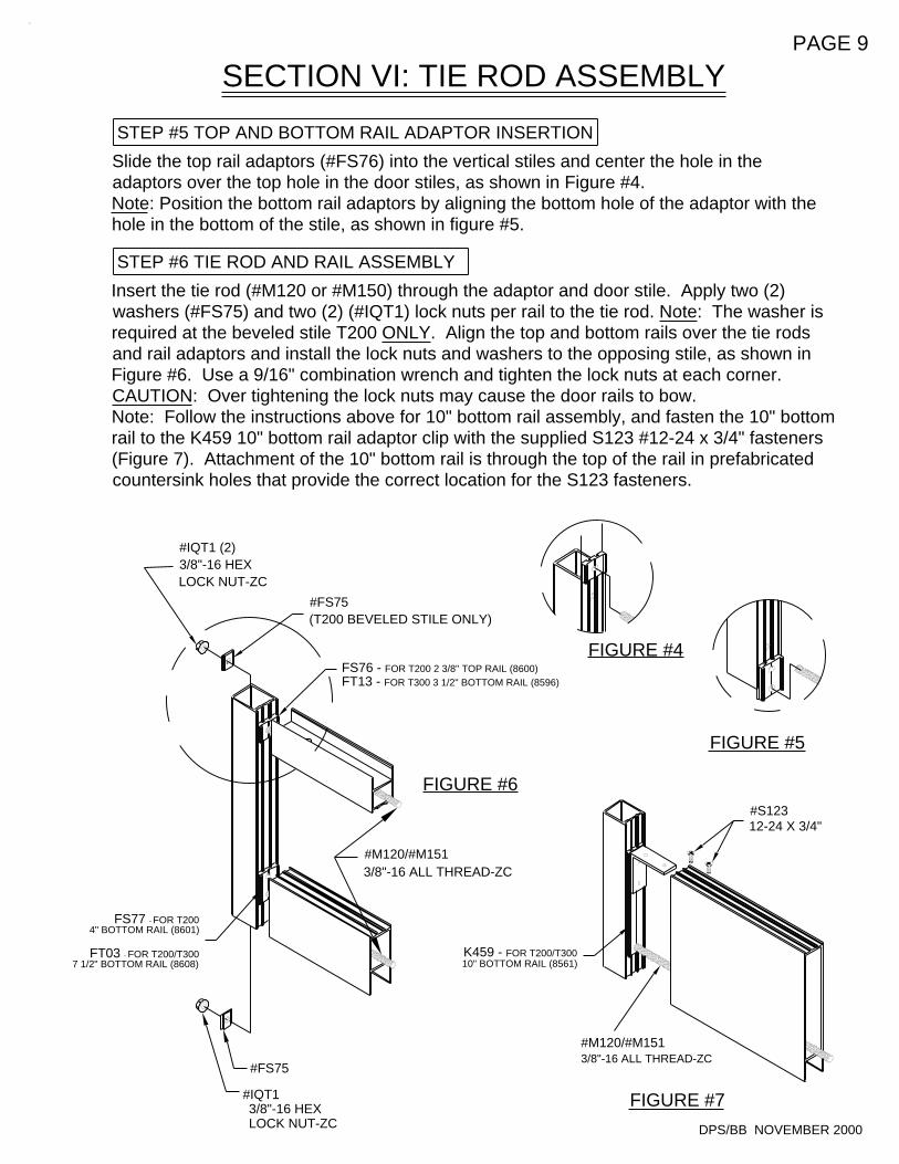
FIGURE #5
3/8"-16 HEX LOCK NUT-ZC
#IQT1
#FS75
FIGURE #4
3/8"-16 ALL THREAD-ZC#M120/#M151
FIGURE #6
SECTION VI: TIE ROD ASSEMBLY
STEP #5 TOP AND BOTTOM RAIL ADAPTOR INSERTION
STEP #6 TIE ROD AND RAIL ASSEMBLY
FIGURE #7
PAGE 9
#FS75(T200 BEVELED STILE ONLY)
FS77 - FOR T200 4" BOTTOM RAIL (8601)
FT03 - FOR T200/T300 7 1/2" BOTTOM RAIL (8608)
#IQT1 (2)3/8"-16 HEXLOCK NUT-ZC
#M120/#M1513/8"-16 ALL THREAD-ZC
K459 - FOR T200/T30010" BOTTOM RAIL (8561)
FS76 - FOR T200 2 3/8" TOP RAIL (8600)FT13 - FOR T300 3 1/2" BOTTOM RAIL (8596)
#S12312-24 X 3/4"
DPS/BB NOVEMBER 2000
Insert the tie rod (#M120 or #M150) through the adaptor and door stile. Apply two (2) washers (#FS75) and two (2) (#IQT1) lock nuts per rail to the tie rod. Note: The washer is required at the beveled stile T200 ONLY. Align the top and bottom rails over the tie rods and rail adaptors and install the lock nuts and washers to the opposing stile, as shown in Figure #6. Use a 9/16" combination wrench and tighten the lock nuts at each corner.CAUTION: Over tightening the lock nuts may cause the door rails to bow. Note: Follow the instructions above for 10" bottom rail assembly, and fasten the 10" bottom rail to the K459 10" bottom rail adaptor clip with the supplied S123 #12-24 x 3/4" fasteners (Figure 7). Attachment of the 10" bottom rail is through the top of the rail in prefabricated countersink holes that provide the correct location for the S123 fasteners.
Slide the top rail adaptors (#FS76) into the vertical stiles and center the hole in the adaptors over the top hole in the door stiles, as shown in Figure #4.Note: Position the bottom rail adaptors by aligning the bottom hole of the adaptor with the hole in the bottom of the stile, as shown in figure #5.
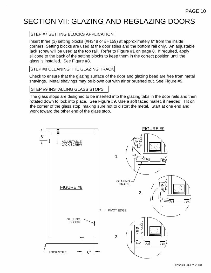
STEP #9 INSTALLING GLASS STOPS
STEP #8 CLEANING THE GLAZING TRACK
FIGURE #8
3.
2.
1.
FIGURE #9
STEP #7 SETTING BLOCKS APPLICATION
SECTION VII: GLAZING AND REGLAZING DOORS
PAGE 10
The glass stops are designed to be inserted into the glazing tabs in the door rails and then rotated down to lock into place. See Figure #9. Use a soft faced mallet, if needed. Hit on the corner of the glass stop, making sure not to distort the metal. Start at one end and work toward the other end of the glass stop.
Check to ensure that the glazing surface of the door and glazing bead are free from metal shavings. Metal shavings may be blown out with air or brushed out. See Figure #9.
Insert three (3) setting blocks (#H348 or #H159) at approximately 6" from the inside corners. Setting blocks are used at the door stiles and the bottom rail only. An adjustable jack screw will be used at the top rail. Refer to Figure #1 on page 8. If required, apply silicone to the back of the setting blocks to keep them in the correct position until the glass is installed. See Figure #8.
LOCK STILE
6"
DPS/BB JULY 2000
6"
GLAZINGTRACK
PIVOT EDGE
SETTINGBLOCK
ADJUSTABLEJACK SCREW
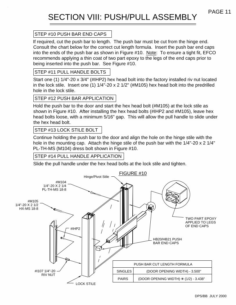
(DOOR OPENING WIDTH) (1/2) - 3.438" PAIRS
SINGLES
STEP #14 PULL HANDLE APPLICATION
FIGURE #10
STEP #11 PULL HANDLE BOLTS
STEP #13 LOCK STILE BOLT
STEP #12 PUSH BAR APPLICATION
(DOOR OPENING WIDTH) - 3.500"
PUSH BAR CUT LENGTH FORMULA
SECTION VIII: PUSH/PULL ASSEMBLY
STEP #10 PUSH BAR END CAPS
PAGE 11
#M1051/4"-20 X 2 1/2
HX-MS 18-8
Continue holding the push bar to the door and align the hole on the hinge stile with the hole in the mounting cap. Attach the hinge stile of the push bar with the 1/4"-20 x 2 1/4" PL-TH-MS (M104) dress bolt shown in Figure #10.
DPS/BB JULY 2000
TWO PART EPOXYAPPLIED TO LEGSOF END CAPS
#I107 1/4"-20RIV NUT
LOCK STILE
Slide the pull handle under the hex head bolts at the lock stile and tighten.
#IHP2
#M1041/4"-20 X 2 1/4
PL-TH-MS 18-8
Hinge/Pivot Stile
HB20/HB21 PUSHBAR END CAPS
Hold the push bar to the door and start the hex head bolt (#M105) at the lock stile as shown in Figure #10. After installing the hex head bolts (#IHP2 and #M105), leave hex head bolts loose, with a minimum 5/16" gap. This will allow the pull handle to slide under the hex head bolt.
Start one (1) 1/4"-20 x 3/4" (#IHP2) hex head bolt into the factory installed riv nut located in the lock stile. Insert one (1) 1/4"-20 x 2 1/2" (#M105) hex head bolt into the predrilled hole in the lock stile.
If required, cut the push bar to length. The push bar must be cut from the hinge end. Consult the chart below for the correct cut length formula. Insert the push bar end caps into the ends of the push bar as shown in Figure #10. Note: To ensure a tight fit, EFCO recommends applying a thin coat of two part epoxy to the legs of the end caps prior to being inserted into the push bar. See Figure #10.
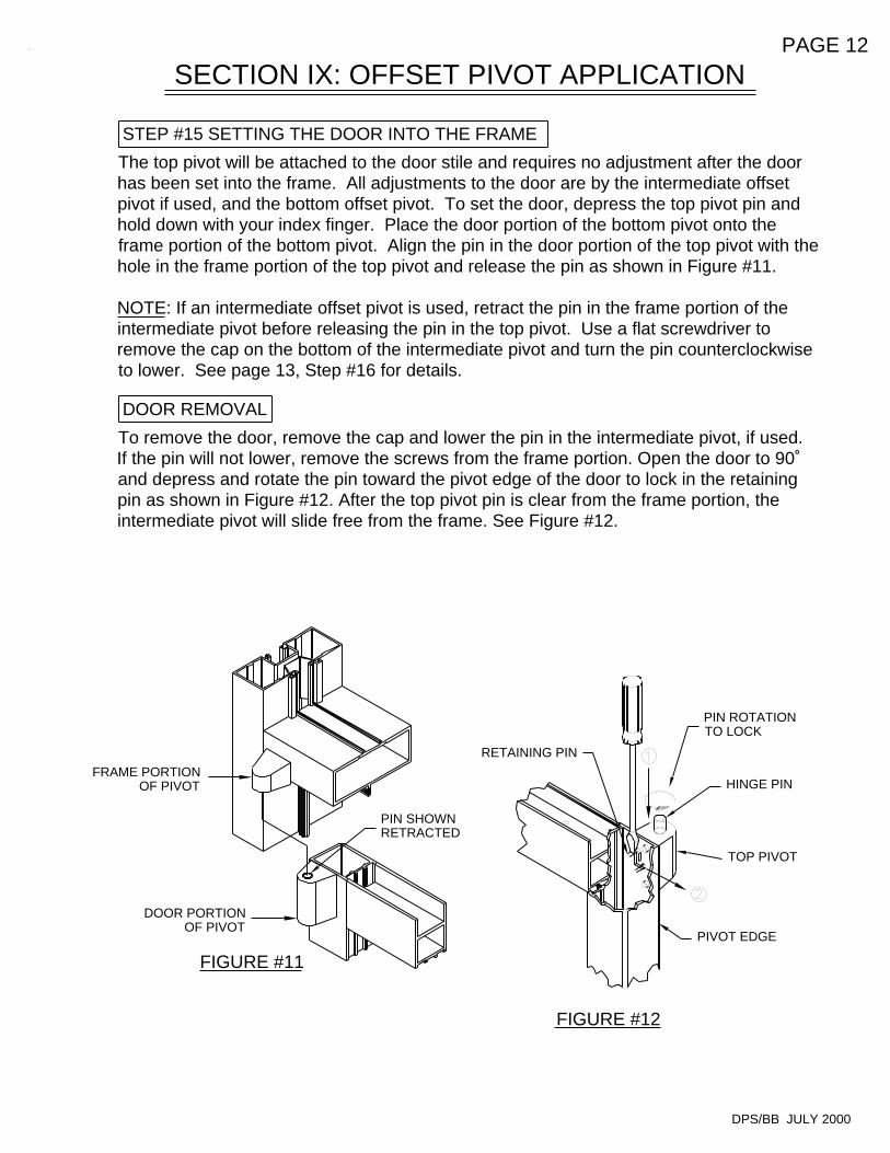
FIGURE #12
SECTION IX: OFFSET PIVOT APPLICATION
FIGURE #11
DOOR REMOVAL
STEP #15 SETTING THE DOOR INTO THE FRAME
PAGE 12
DPS/BB JULY 2000
PIVOT EDGE
TOP PIVOT
HINGE PIN
PIN ROTATIONTO LOCK
FRAME PORTIONOF PIVOT
DOOR PORTIONOF PIVOT
PIN SHOWNRETRACTED
RETAINING PIN
To remove the door, remove the cap and lower the pin in the intermediate pivot, if used. If the pin will not lower, remove the screws from the frame portion. Open the door to 90˚ and depress and rotate the pin toward the pivot edge of the door to lock in the retaining pin as shown in Figure #12. After the top pivot pin is clear from the frame portion, the intermediate pivot will slide free from the frame. See Figure #12.
The top pivot will be attached to the door stile and requires no adjustment after the door has been set into the frame. All adjustments to the door are by the intermediate offset pivot if used, and the bottom offset pivot. To set the door, depress the top pivot pin and hold down with your index finger. Place the door portion of the bottom pivot onto the frame portion of the bottom pivot. Align the pin in the door portion of the top pivot with the hole in the frame portion of the top pivot and release the pin as shown in Figure #11.
NOTE: If an intermediate offset pivot is used, retract the pin in the frame portion of the intermediate pivot before releasing the pin in the top pivot. Use a flat screwdriver to remove the cap on the bottom of the intermediate pivot and turn the pin counterclockwise to lower. See page 13, Step #16 for details.
DOOR REMOVAL
STEP #16 SETTING THE DOOR INTO THE FRAME
SECTION IX: OFFSET PIVOT APPLICATION (CONT.)
PAGE 13
FIGURE #13
DPS/BB JULY 2000
DOOR PORTIONOF PIVOT
PIVOT PIN
PIVOT CAP
FRAME PORTIONOF PIVOT
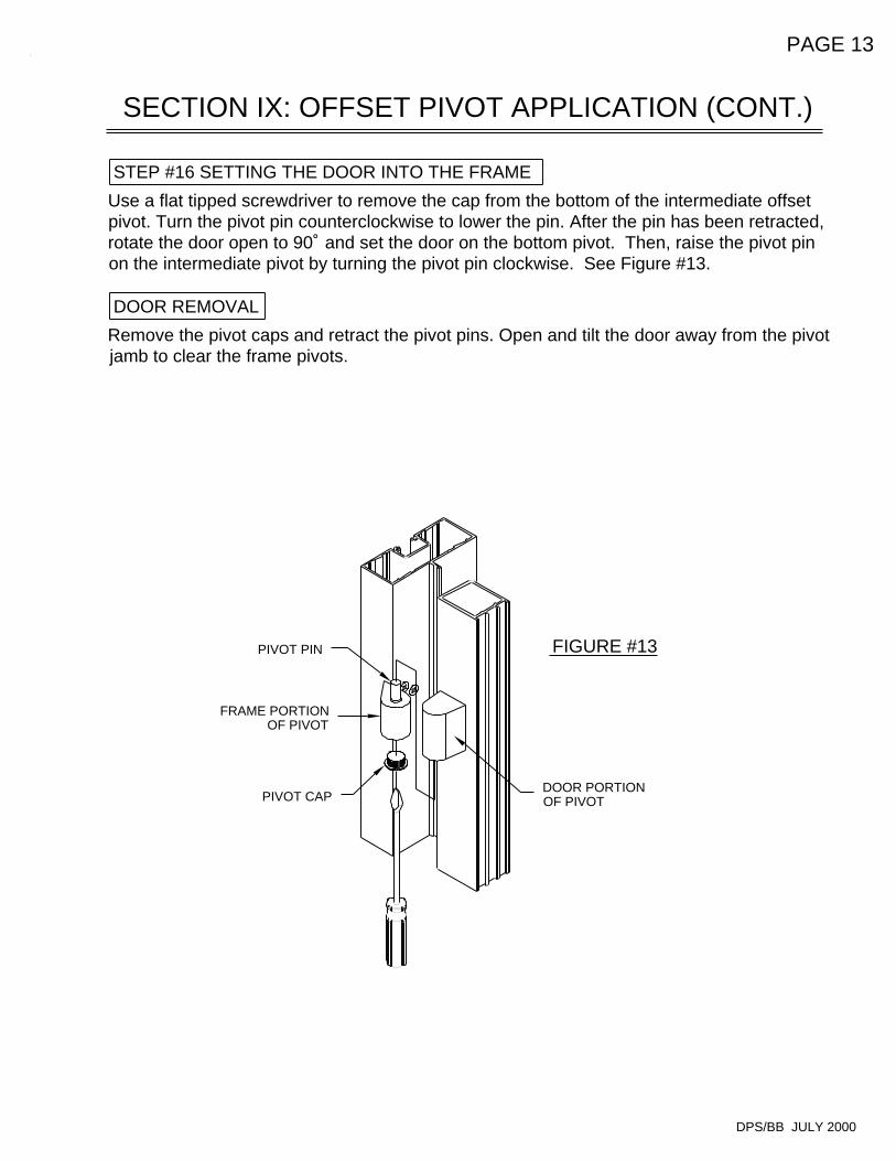
Remove the pivot caps and retract the pivot pins. Open and tilt the door away from the pivot jamb to clear the frame pivots.
Use a flat tipped screwdriver to remove the cap from the bottom of the intermediate offset pivot. Turn the pivot pin counterclockwise to lower the pin. After the pin has been retracted, rotate the door open to 90˚ and set the door on the bottom pivot. Then, raise the pivot pin on the intermediate pivot by turning the pivot pin clockwise. See Figure #13.
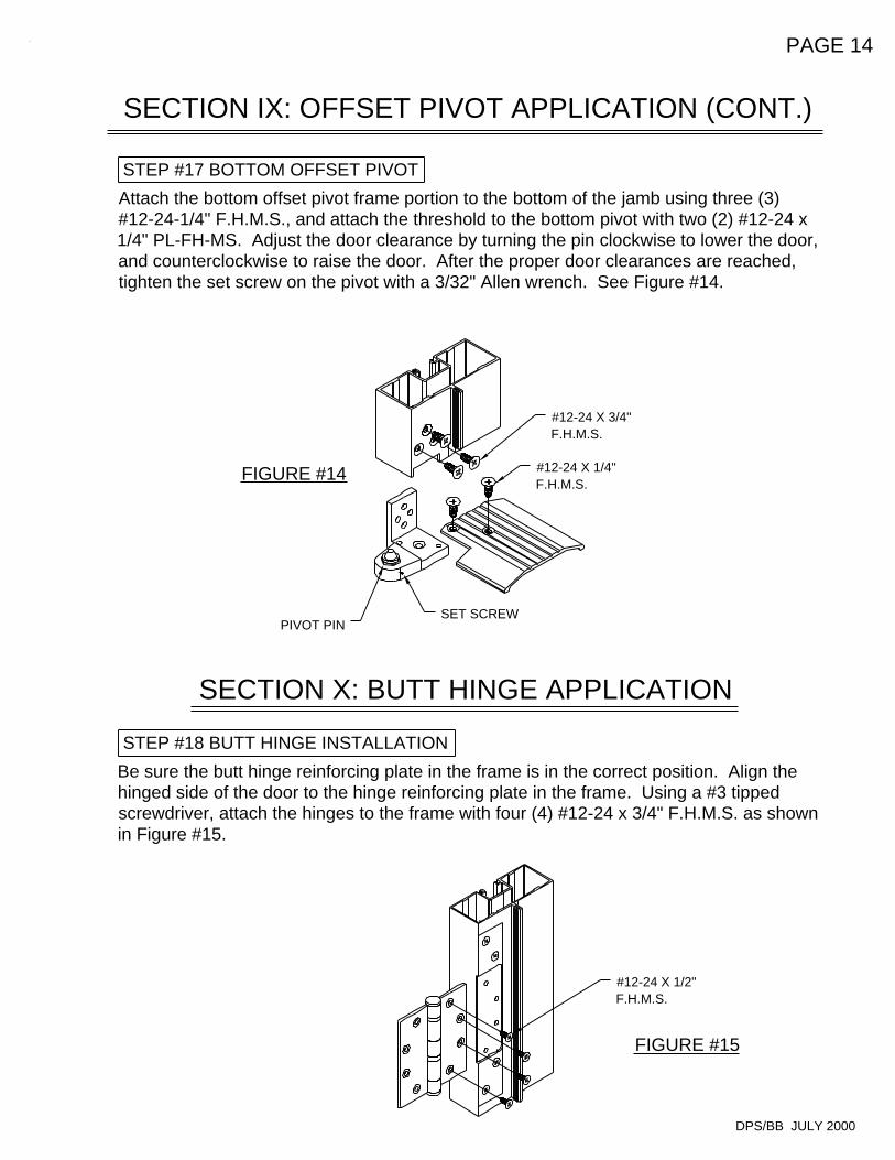
FIGURE #15
SECTION X: BUTT HINGE APPLICATION
STEP #18 BUTT HINGE INSTALLATION
FIGURE #14
SECTION IX: OFFSET PIVOT APPLICATION (CONT.)
STEP #17 BOTTOM OFFSET PIVOT
PAGE 14
DPS/BB JULY 2000
#12-24 X 1/2"F.H.M.S.
#12-24 X 1/4"F.H.M.S.
#12-24 X 3/4"F.H.M.S.
PIVOT PINSET SCREW
Be sure the butt hinge reinforcing plate in the frame is in the correct position. Align the hinged side of the door to the hinge reinforcing plate in the frame. Using a #3 tipped screwdriver, attach the hinges to the frame with four (4) #12-24 x 3/4" F.H.M.S. as shown in Figure #15.
Attach the bottom offset pivot frame portion to the bottom of the jamb using three (3) #12-24-1/4" F.H.M.S., and attach the threshold to the bottom pivot with two (2) #12-24 x 1/4" PL-FH-MS. Adjust the door clearance by turning the pin clockwise to lower the door, and counterclockwise to raise the door. After the proper door clearances are reached, tighten the set screw on the pivot with a 3/32" Allen wrench. See Figure #14.
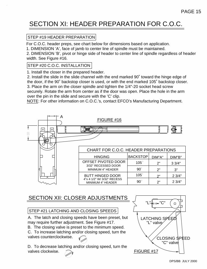
STEP #21 LATCHING AND CLOSING SPEEDS
FIGURE #17
"C" valveCLOSING SPEED
"L" valveLATCHING SPEED
4"x 4 1/2" W/ 3/32" RECESS
OFFSET PIVOTED DOOR
SECTION XII: CLOSER ADJUSTMENTS
90
105
CHART FOR C.O.C. HEADER PREPARATIONS
90
105
BACKSTOP
BUTT HINGED DOOR
MINIMUM 4" HEADER
MINIMUM 4" HEADER3/32" RECESSED DOOR
HINGING
2" 2 3/4"
2 3/4"2"
"C""L"
DIM"B"
3 3/4"
2"
2"
DIM"A"
3"
FIGURE #16
10590
STEP #20 C.O.C. INSTALLATION
STEP #19 HEADER PREPARATION
SECTION XI: HEADER PREPARATION FOR C.O.C.
PAGE 15
A
DPS/BB JULY 2000
A. The latch and closing speeds have been preset, but may require further adjustment. See Figure #17.B. The closing valve is preset to the minimum speed.C. To increase latching and/or closing speed, turn the valves counterclockwise.
D. To decrease latching and/or closing speed, turn the valves clockwise.
1. Install the closer in the prepared header.2. Install the slide in the slide channel with the end marked 90˚ toward the hinge edge of the door, if the 90˚ backstop closer is used, or with the end marked 105˚ backstop closer.3. Place the arm on the closer spindle and tighten the 1/4"-20 socket head screw securely. Rotate the arm from center as if the door was open. Place the hole in the arm over the pin in the slide and secure with the ’C’ clip.NOTE: For other information on C.O.C.’s, contact EFCO’s Manufacturing Department.
For C.O.C. header preps, see chart below for dimensions based on application.1. DIMENSION ’A’, face of jamb to center line of spindle must be maintained.2. DIMENSION ’B’, pivot or hinge side of header to center line of spindle regardless of header width. See Figure #16.
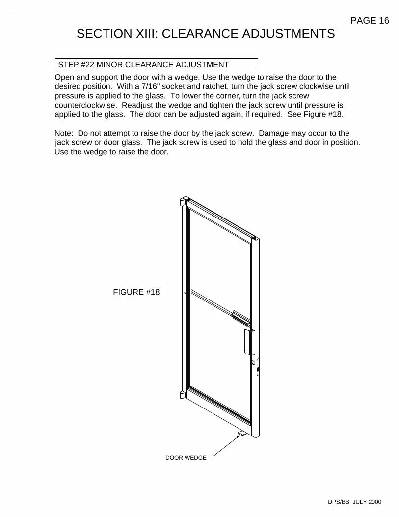
FIGURE #18
SECTION XIII: CLEARANCE ADJUSTMENTS
STEP #22 MINOR CLEARANCE ADJUSTMENT
PAGE 16
DPS/BB JULY 2000
DOOR WEDGE
Open and support the door with a wedge. Use the wedge to raise the door to the desired position. With a 7/16" socket and ratchet, turn the jack screw clockwise until pressure is applied to the glass. To lower the corner, turn the jack screw counterclockwise. Readjust the wedge and tighten the jack screw until pressure is applied to the glass. The door can be adjusted again, if required. See Figure #18.
Note: Do not attempt to raise the door by the jack screw. Damage may occur to the jack screw or door glass. The jack screw is used to hold the glass and door in position. Use the wedge to raise the door.
HINGED STILE CUTOFF
11/16" MAX.
1 1/8"
FIGURE #19
MIN.
LOCK STILE CUTOFF
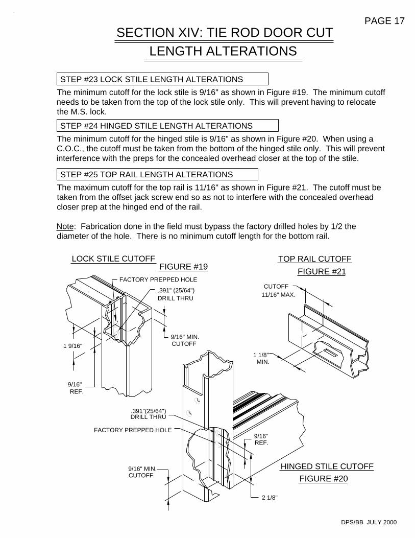
STEP #25 TOP RAIL LENGTH ALTERATIONS
CUTOFF
FIGURE #20
TOP RAIL CUTOFF
FIGURE #21
SECTION XIV: TIE ROD DOOR CUT
STEP #23 LOCK STILE LENGTH ALTERATIONS
STEP #24 HINGED STILE LENGTH ALTERATIONS
9/16" MIN.CUTOFF
9/16"REF.
9/16" MIN. CUTOFF
9/16"REF.
LENGTH ALTERATIONS
PAGE 17
The maximum cutoff for the top rail is 11/16" as shown in Figure #21. The cutoff must be taken from the offset jack screw end so as not to interfere with the concealed overhead closer prep at the hinged end of the rail.
Note: Fabrication done in the field must bypass the factory drilled holes by 1/2 the diameter of the hole. There is no minimum cutoff length for the bottom rail.
DPS/BB JULY 2000
FACTORY PREPPED HOLE
.391"(25/64")DRILL THRU
.391" (25/64")DRILL THRU
FACTORY PREPPED HOLE
The minimum cutoff for the hinged stile is 9/16" as shown in Figure #20. When using a C.O.C., the cutoff must be taken from the bottom of the hinged stile only. This will prevent interference with the preps for the concealed overhead closer at the top of the stile.
The minimum cutoff for the lock stile is 9/16" as shown in Figure #19. The minimum cutoff needs to be taken from the top of the lock stile only. This will prevent having to relocate the M.S. lock.
1 9/16"
2 1/8"
Recommended