®
Side
Mounted
Float Level
Switch
Installation and Operating Manual
Tuffy® T3Liquid Level Controlswith Electric Switches
2
UNPACKING
Unpack the instrument carefully. Make sure all componentshave been removed from the foam protection. Inspect allcomponents for damage. Report any concealed damage tothe carrier within 24 hours. Check the contents of the car-ton/crates against the packing slip and report any discrep-ancies to Magnetrol. Check the nameplate model number(Model number/approvals as per inserted separate sheet) tobe sure it agrees with the packing slip and purchase order.Check and record the serial number for future referencewhen ordering parts.
MOUNTING
Nameplate:- partnumber- switch- serial n°- tag n°
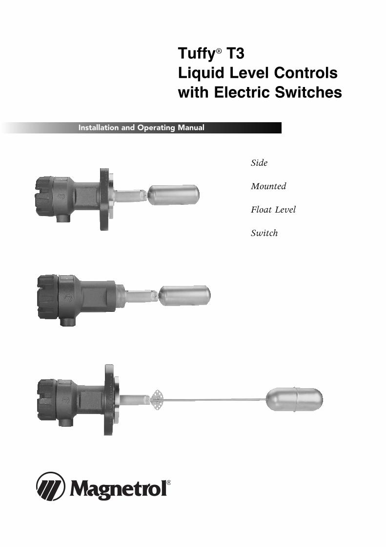
For flanged units
2" NPT Tuffy External cage mounted TuffyFlanged Tuffy
Cut and remove the plastic shipping straps on flanged units.
Flangedmax nozzle length:85 mm (3.35")
Field adjustabledifferentialmax nozzle length:110 mm (4.35")
Interfacemax nozzle length:147 mm (5.80")
Threadedmax nozzle length:84 mm (3.29")
Cagemounted
Air
Oil
Water
Locking screw, loosen before removing cover(refasten after replacing)
Locking screw, loosenbefore removing cover(refasten after replacing)
M20 x 1.5 or 3/4" NPTcable entry; shouldalways be pointingdown
Apply Teflon tapeor Petrolatum
Use wrench size 65 mm
1. Install a propergasket.
2. Cut and removethe shippingstraps, slide thecontrol in thenozzle and alignthe bold holes.
3. M20 x 1.5 or 3/4" NPTcable entry; shouldalways be pointingdown
4. Fasten bolts andstuds in a star pattern
CL CL CL
Pressurevessel
Switchactuationlevel
Drain valve
3/4"NPTcable entry
Safetycheckvalve
Shut-offvalve
Shut-offvalve
Note: min nozzle size is 3" SCH 80 (max nozzle lengths are specified as per this size)
These units are in conformity with the provisions of:1. Directive 94/9/EC for Equipment or protective system for use in potentially explosive atmospheres.
Ex d models: EC-type examination certificate number ISSeP10ATEX032.Notified Body: ISSeP, notified body N° 0492, Zoning A. Schweitzer, B7340 Colfontaine, Belgium.The following harmonized standards have been applied: EN 60079-0:2009 / EN 60079-1:2007 /
EN 60079-26:2007Ex ia models: EC-type examination certificate number ISSeP00ATEX010X.Notified Body: ISSeP, notified body N° 0492, Zoning A. Schweitzer, B7340 Colfontaine, Belgium.The following standards have been applied: EN 50014: 1997 +A1 + A2 / EN 50020: 1994 / EN 50284: 1999
2. The PED directive 97/23/EC (pressure equipment directive). Safety accessories per category IV module H1.Notified body: Lloyd's Register of Shipping, 71, Fenchurch Street, London EC 3M-4BS, UK, notified body N° 0038. Thefollowing standard has been applied: ANSI/ASME B31.3
00380344
3
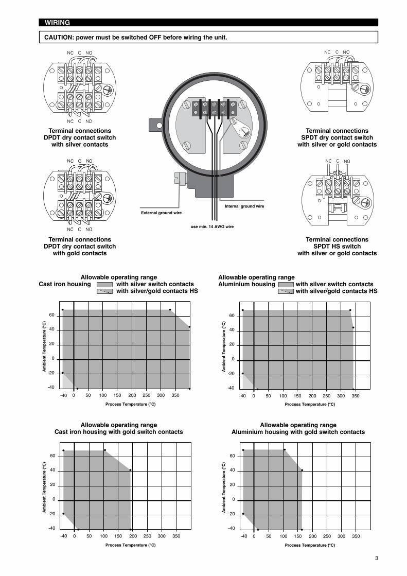
WIRING
CAUTION: power must be switched OFF before wiring the unit.
Allowable operating rangeCast iron housing with silver switch contacts
with silver/gold contacts HS
Internal ground wire
use min. 14 AWG wire
External ground wire
Terminal connectionsDPDT dry contact switchwith silver contacts
Terminal connectionsDPDT dry contact switch
with gold contacts
Terminal connectionsSPDT dry contact switchwith silver or gold contacts
Terminal connectionsSPDT HS switch
with silver or gold contacts
0 50 100 150 200 250 300 350
0
20
40
60
-20
-40-40
Process Temperature (°C)
AmbientTemperature(°C)
Allowable operating rangeAluminium housing with silver switch contacts
with silver/gold contacts HS
0 50 100 150 200 250 300 350
0
20
40
60
-20
-40-40
Process Temperature (°C)
AmbientTemperature(°C)
Allowable operating rangeCast iron housing with gold switch contacts
0 50 100 150 200 250 300 350
0
20
40
60
-20
-40-40
Process Temperature (°C)
AmbientTemperature(°C)
Allowable operating rangeAluminium housing with gold switch contacts
0 50 100 150 200 250 300 350
0
20
40
60
-20
-40-40
Process Temperature (°C)
AmbientTemperature(°C)
4
TROUBLESHOOTING
Symptom Cause of malfunction / Action
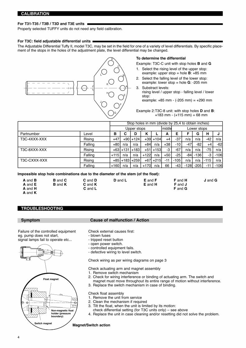
Failure of the controlled equipment Check external causes first:eg. pump does not start, - blown fusessignal lamps fail to operate etc... - tripped reset button
- open power switch.- controlled equipment fails.- defective wiring to level switch.
Check wiring as per wiring diagrams on page 3
Check actuating arm and magnet assembly1. Remove switch mechanism2. Check for wiring interference or binding of actuating arm. The switch and
magnet must move throughout its entire range of motion without interference.3. Replace the switch mechanism in case of binding.
Check float assembly1. Remove the unit from service2. Clean the mechanism if required3. Tilt the float, when the unit is limited by its motion:
check differential setting (for T3C units only) – see above4. Replace the unit in case cleaning and/or resetting did not solve the problem.
Float magnet
Switch magnet
Non-magnetic floatholder (pressureboundary)
Magnet/Switch action
For T31-T35 / T3B / T3D and T3E units
CALIBRATION
Properly selected TUFFY units do not need any field calibration.
For T3C: field adjustable differential unitsThe Adjustable Differential Tuffy II, model T3C, may be set in the field for one of a variety of level differentials. By specific place-ment of the stops in the holes of the adjustment plate, the level differential may be changed.
D
C
B
A
E
JF
G
K
L
H
To determine the differentialExample: T3C-C unit with stop holes B and G1. Select the rising level of the upper stop:
example: upper stop = hole B: +85 mm2. Select the falling level of the lower stop:
example: lower stop = hole G: -205 mm3. Substract levels:
rising level / upper stop - falling level / lowerstop:example: +85 mm - (-205 mm) = +290 mm
Example 2:T3C-8 unit: with stop holes D and B:+183 mm - (+115 mm) = 68 mm
Impossible stop hole combinations due to the diameter of the stem (of the float):
Stop holes in mm (divide by 25,4 to obtain inches)Upper stops middle Lower stops
Partnumber Level B C D K L A E F G H JT3C-4XXX-XXX Rising +47 +90 +124 +39 +104 +4 -37 n/a n/a -42 n/a
Falling +80 n/a n/a +84 n/a +38 -10 -47 -82 +4 -62T3C-8XXX-XXX Rising +63 +131 +183 +51 +153 -3 -67 n/a n/a -75 n/a
Falling +115 n/a n/a +122 n/a +50 -25 -84 -136 -3 -106T3C-CXXX-XXX Rising +85 +183 +259 +67 +215 -11 -105 n/a n/a -115 n/a
Falling +160 n/a n/a +170 n/a 66 -43 -128 -205 -11 -106
A and BA and EA and HA and K
B and CB and K
C and DC and KC and L
D and L E and FE and H
F and HF and JF and G
J and G
5
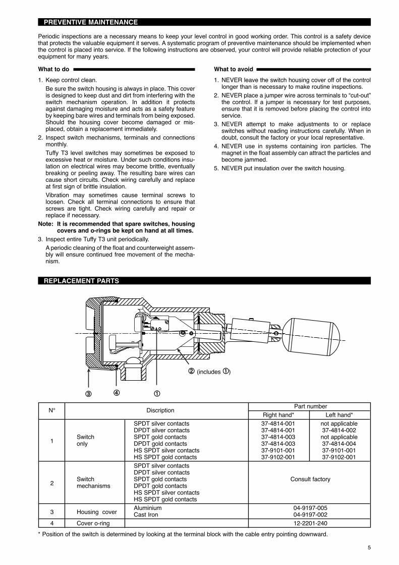
REPLACEMENT PARTS
PREVENTIVE MAINTENANCE
Periodic inspections are a necessary means to keep your level control in good working order. This control is a safety devicethat protects the valuable equipment it serves. A systematic program of preventive maintenance should be implemented whenthe control is placed into service. If the following instructions are observed, your control will provide reliable protection of yourequipment for many years.
What to do1. Keep control clean.
Be sure the switch housing is always in place. This coveris designed to keep dust and dirt from interfering with theswitch mechanism operation. In addition it protectsagainst damaging moisture and acts as a safety featureby keeping bare wires and terminals from being exposed.Should the housing cover become damaged or mis-placed, obtain a replacement immediately.
2. Inspect switch mechanisms, terminals and connectionsmonthly.Tuffy T3 level switches may sometimes be exposed toexcessive heat or moisture. Under such conditions insu-lation on electrical wires may become brittle, eventuallybreaking or peeling away. The resulting bare wires cancause short circuits. Check wiring carefully and replaceat first sign of brittle insulation.Vibration may sometimes cause terminal screws toloosen. Check all terminal connections to ensure thatscrews are tight. Check wiring carefully and repair orreplace if necessary.
Note: It is recommended that spare switches, housingcovers and o-rings be kept on hand at all times.
3. Inspect entire Tuffy T3 unit periodically.A periodic cleaning of the float and counterweight assem-bly will ensure continued free movement of the mecha-nism.
What to avoid1. NEVER leave the switch housing cover off of the control
longer than is necessary to make routine inspections.2. NEVER place a jumper wire across terminals to “cut-out”
the control. If a jumper is necessary for test purposes,ensure that it is removed before placing the control intoservice.
3. NEVER attempt to make adjustments to or replaceswitches without reading instructions carefully. When indoubt, consult the factory or your local representative.
4. NEVER use in systems containing iron particles. Themagnet in the float assembly can attract the particles andbecome jammed.
5. NEVER put insulation over the switch housing.
N° Discription Part numberRight hand* Left hand*
SPDT silver contacts 37-4814-001 not applicableDPDT silver contacts 37-4814-001 37-4814-002
1 Switch SPDT gold contacts 37-4814-003 not applicableonly DPDT gold contacts 37-4814-003 37-4814-004
HS SPDT silver contacts 37-9101-001 37-9101-001HS SPDT gold contacts 37-9102-001 37-9102-001SPDT silver contactsDPDT silver contacts
2 Switch SPDT gold contacts Consult factorymechanisms DPDT gold contacts
HS SPDT silver contactsHS SPDT gold contacts
3 Housing cover Aluminium 04-9197-005Cast Iron 04-9197-002
4 Cover o-ring 12-2201-240* Position of the switch is determined by looking at the terminal block with the cable entry pointing downward.
���� ��
�� (includes ��)
6
SPECIFICATIONS
Description SpecificationSwitch ratings Up to 10 A @ 240 V AC
Up to 6.0 A @ 24 V DCSignal output Single SPDT or single DPDT contactsSwitch types Dry contact with silver or gold plated contacts
Hermetically sealed for corrosive environmentApprovals ATEX II 1/2 G / IECEx Ex d IIC T6 Ga/Gb, explosion proof
ATEX II 1G EEx ia II C T6, intrinsically safeNEMA 4X/7/9, Class 1, Div 1, Groups B, C & D
Cable entries 3/4" NPT or M20 x 1,5
PHYSICAL SPECIFICATIONS
ELECTRICAL SPECIFICATIONS
Description SpecificationMeasured variable Liquid levelPhysical range Narrow differential: 13 mm (0.5")
Adjustable differential: up to 464 mm (18.26")Interface Service Differential: 44 mm (1.72")Interface: min S.G. difference between both liquids: 0,1
Ambient temperature -40 °C to + 70 °C (-40 °F to +160 °F)Process temperature From -55 °C (-65 °F) up to 400 °C (750 °F) depending switch/housing selectionProcess pressure Standard models: up to 50 bar abs. (720 psi)
High pressure models: up to 150 bar abs. (2160 psi) Wetted parts 316/316L (1.4401/1.4404) or Hastelloy C (2.4819)Flange materials Carbon steel
316/316L (1.4401/1.4404) or Carbon steel with 316/316L (1.4401/1.4404) claddingHastelloy C (2.4819) or Carbon steel with Hastelloy C (2.4819) cladding
Housing materials Cast aluminium or cast iron
7
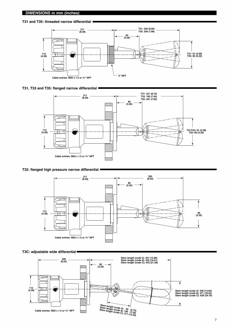
DIMENSIONS in mm (inches)
T31 and T35: threaded narrow differential
T31, T33 and T35: flanged narrow differential
T32: flanged high pressure narrow differential
112(4.39)
211(8.29)
84(3.29)
T31: 91 (3.59)T35: 85 (3.33)
T31: 220 (8.66)T35: 200 (7.86)
2" NPTCable entries: M20 x 1.5 or 3/4" NPT
112(4.39)
211(8.29)
85(3.35)
T31/T33: 91 (3.59)T35: 85 (3.33)
T31: 221 (8.72)T33: 190 (7.50)T35: 201 (7.92)
Cable entries: M20 x 1.5 or 3/4" NPT
112(4.39)
211(8.29)
204(8.02)
85(3.35)
85(3.35)
Cable entries: M20 x 1.5 or 3/4" NPT
T3C: adjustable wide differential
112(4.39)
209(8.23)
Stem length (code 4): 95 (3.75)Stem length (code 8): 190 (7.50)Stem length (code C): 311 (12.25)
Stem length (code 4): 346 (13.62)Stem length (code 8): 471 (18.54)Stem length (code C): 629 (24.76)
Stem length (code 4): 327 (12.86)Stem length (code 8): 422 (16.61)Stem length (code C): 543 (21.36)85
(3.35)
Cable entries: M20 x 1.5 or 3/4" NPT
8
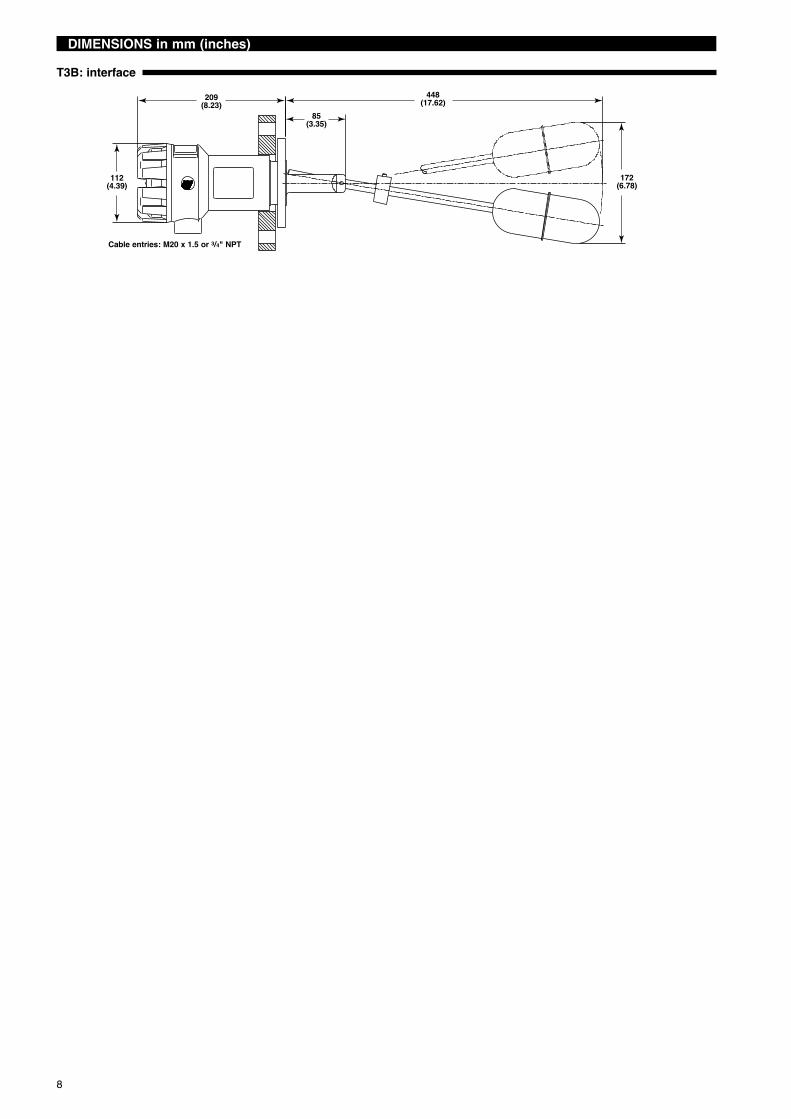
T3B: interface209(8.23)
112(4.39)
85(3.35)
448(17.62)
172(6.78)
Cable entries: M20 x 1.5 or 3/4" NPT
DIMENSIONS in mm (inches)
9
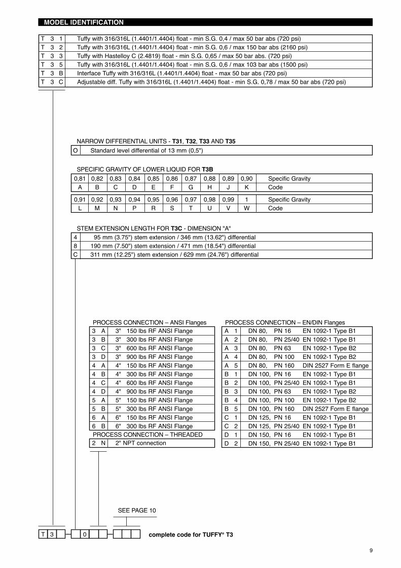
MODEL IDENTIFICATION
T 3 1 Tuffy with 316/316L (1.4401/1.4404) float - min S.G. 0,4 / max 50 bar abs (720 psi)T 3 2 Tuffy with 316/316L (1.4401/1.4404) float - min S.G. 0,6 / max 150 bar abs (2160 psi)T 3 3 Tuffy with Hastelloy C (2.4819) float - min S.G. 0,65 / max 50 bar abs. (720 psi)T 3 5 Tuffy with 316/316L (1.4401/1.4404) float - min S.G. 0,6 / max 103 bar abs (1500 psi)T 3 B Interface Tuffy with 316/316L (1.4401/1.4404) float - max 50 bar abs (720 psi)T 3 C Adjustable diff. Tuffy with 316/316L (1.4401/1.4404) float - min S.G. 0,78 / max 50 bar abs (720 psi)
T 03 complete code for TUFFY® T3
PROCESS CONNECTION – ANSI Flanges3 A 3" 150 lbs RF ANSI Flange3 B 3" 300 lbs RF ANSI Flange3 C 3" 600 lbs RF ANSI Flange3 D 3" 900 lbs RF ANSI Flange4 A 4" 150 lbs RF ANSI Flange4 B 4" 300 lbs RF ANSI Flange4 C 4" 600 lbs RF ANSI Flange4 D 4" 900 lbs RF ANSI Flange5 A 5" 150 lbs RF ANSI Flange5 B 5" 300 lbs RF ANSI Flange6 A 6" 150 lbs RF ANSI Flange6 B 6" 300 lbs RF ANSI FlangePROCESS CONNECTION – THREADED2 N 2" NPT connection
PROCESS CONNECTION – EN/DIN FlangesA 1 DN 80, PN 16 EN 1092-1 Type B1A 2 DN 80, PN 25/40 EN 1092-1 Type B1A 3 DN 80, PN 63 EN 1092-1 Type B2A 4 DN 80, PN 100 EN 1092-1 Type B2A 5 DN 80, PN 160 DIN 2527 Form E flangeB 1 DN 100, PN 16 EN 1092-1 Type B1B 2 DN 100, PN 25/40 EN 1092-1 Type B1B 3 DN 100, PN 63 EN 1092-1 Type B2B 4 DN 100, PN 100 EN 1092-1 Type B2B 5 DN 100, PN 160 DIN 2527 Form E flangeC 1 DN 125, PN 16 EN 1092-1 Type B1C 2 DN 125, PN 25/40 EN 1092-1 Type B1D 1 DN 150, PN 16 EN 1092-1 Type B1D 2 DN 150, PN 25/40 EN 1092-1 Type B1
STEM EXTENSION LENGTH FOR T3C - DIMENSION "A"4 95 mm (3.75") stem extension / 346 mm (13.62") differential8 190 mm (7.50") stem extension / 471 mm (18.54") differentialC 311 mm (12.25") stem extension / 629 mm (24.76") differential
NARROW DIFFERENTIAL UNITS - T31, T32, T33 AND T35O Standard level differential of 13 mm (0,5")
0,81 0,82 0,83 0,84 0,85 0,86 0,87 0,88 0,89 0,90 Specific GravityA B C D E F G H J K Code
0,91 0,92 0,93 0,94 0,95 0,96 0,97 0,98 0,99 1 Specific GravityL M N P R S T U V W Code
SPECIFIC GRAVITY OF LOWER LIQUID FOR T3B
SEE PAGE 10
10
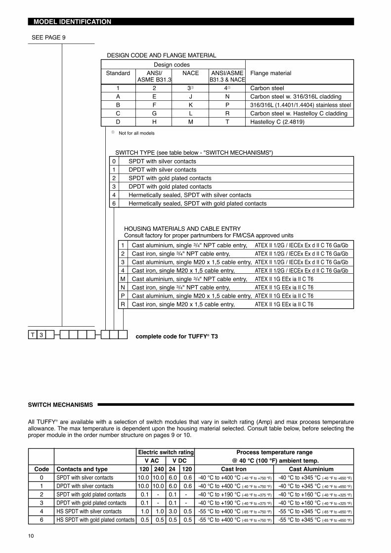
SWITCH MECHANISMS
SWITCH TYPE (see table below - "SWITCH MECHANISMS")0 SPDT with silver contacts1 DPDT with silver contacts2 SPDT with gold plated contacts3 DPDT with gold plated contacts4 Hermetically sealed, SPDT with silver contacts6 Hermetically sealed, SPDT with gold plated contacts
T 3 complete code for TUFFY® T3
DESIGN CODE AND FLANGE MATERIALDesign codes
Standard ANSI/ NACE ANSI/ASME Flange materialASME B31.3 B31.3 & NACE
1 2 3� 4� Carbon steelA E J N Carbon steel w. 316/316L claddingB F K P 316/316L (1.4401/1.4404) stainless steelC G L R Carbon steel w. Hastelloy C claddingD H M T Hastelloy C (2.4819)
MODEL IDENTIFICATION
SEE PAGE 9
HOUSING MATERIALS AND CABLE ENTRYConsult factory for proper partnumbers for FM/CSA approved units1 Cast aluminium, single 3/4" NPT cable entry, ATEX II 1/2G / IECEx Ex d II C T6 Ga/Gb2 Cast iron, single 3/4" NPT cable entry, ATEX II 1/2G / IECEx Ex d II C T6 Ga/Gb3 Cast aluminium, single M20 x 1,5 cable entry, ATEX II 1/2G / IECEx Ex d II C T6 Ga/Gb4 Cast iron, single M20 x 1,5 cable entry, ATEX II 1/2G / IECEx Ex d II C T6 Ga/GbM Cast aluminium, single 3/4" NPT cable entry, ATEX II 1G EEx ia II C T6N Cast iron, single 3/4" NPT cable entry, ATEX II 1G EEx ia II C T6P Cast aluminium, single M20 x 1,5 cable entry, ATEX II 1G EEx ia II C T6R Cast iron, single M20 x 1,5 cable entry, ATEX II 1G EEx ia II C T6
All TUFFY® are available with a selection of switch modules that vary in switch rating (Amp) and max process temperatureallowance. The max temperature is dependent upon the housing material selected. Consult table below, before selecting theproper module in the order number structure on pages 9 or 10.
Electric switch rating Process temperature rangeV AC V DC @ 40 °C (100 °F) ambient temp.
Code Contacts and type 120 240 24 120 Cast Iron Cast Aluminium0 SPDT with silver contacts 10.0 10.0 6.0 0.6 -40 °C to +400 °C (-40 °F to +750 °F) -40 °C to +345 °C (-40 °F to +650 °F)1 DPDT with silver contacts 10.0 10.0 6.0 0.6 -40 °C to +400 °C (-40 °F to +750 °F) -40 °C to +345 °C (-40 °F to +650 °F)2 SPDT with gold plated contacts 0.1 - 0.1 - -40 °C to +190 °C (-40 °F to +375 °F) -40 °C to +160 °C (-40 °F to +325 °F)3 DPDT with gold plated contacts 0.1 - 0.1 - -40 °C to +190 °C (-40 °F to +375 °F) -40 °C to +160 °C (-40 °F to +325 °F)4 HS SPDT with silver contacts 1.0 1.0 3.0 0.5 -55 °C to +400 °C (-65 °F to +750 °F) -55 °C to +345 °C (-65 °F to +650 °F)6 HS SPDT with gold plated contacts 0.5 0.5 0.5 0.5 -55 °C to +400 °C (-65 °F to +750 °F) -55 °C to +345 °C (-65 °F to +650 °F)
� Not for all models

11
IMPORTANTSERVICE POLICY
Owners of Magnetrol products may request the return of a control; or, any part of a control for complete rebuilding or replacement. They will be rebuilt or replaced promptly. Magnetrol International will repair or replace the control, at no cost tothe purchaser, (or owner) other than transportation cost if:
a. Returned within the warranty period; and,b. The factory inspection finds the cause of the malfunction to be defective material or workmanship.
If the trouble is the result of conditions beyond our control; or, is NOT covered by the warranty, there will be charges for labourand the parts required to rebuild or replace the equipment.In some cases, it may be expedient to ship replacement parts; or, in extreme cases a complete new control, to replace theoriginal equipment before it is returned. If this is desired, notify the factory of both the model and serial numbers of the control to be replaced. In such cases, credit for the materials returned, will be determined on the basis of the applicability ofour warranty.No claims for misapplication, labour, direct or consequential damage will be allowed.
RETURNED MATERIAL PROCEDURESo that we may efficiently process any materials that are returned, it is essential that a “Return Material Authorisation” (RMA)form will be obtained from the factory. It is mandatory that this form will be attached to each material returned. This form isavailable through Magnetrol’s local representative or by contacting the factory. Please supply the following information:
1. Purchaser Name2. Description of Material3. Serial Number and Ref Number4. Desired Action5. Reason for Return6. Process details
All shipments returned to the factory must be by prepaid transportation. Magnetrol will not accept collect shipments.
All replacements will be shipped FOB factory.
www.magnetrol.com
BENELUX Heikensstraat 6, 9240 Zele, België -BelgiqueFRANCE Tel. +32 (0)52.45.11.11 • Fax. +32 (0)52.45.09.93 • E-Mail: [email protected] Alte Ziegelei 2-4, D-51491 Overath Tel. +49 (0)2204 / 9536-0 • Fax. +49 (0)2204 / 9536-53 • E-Mail: [email protected] C-20 Community Centre, Janakpuri, New Delhi - 110 058 Tel. +91 (11) 41661840 • Fax +91 (11) 41661843 • E-Mail: [email protected] Via Arese 12, I-20159 Milano Tel. +39 02 607.22.98 • Fax. +39 02 668.66.52 • E-Mail: [email protected] 198095 Saint-Petersburg, Marshala Govorova street, house 35A, office 427 Tel. +7-812.702.70.87 • E-Mail: [email protected]. DAFZA Office 5EA 722 • PO Box 293671 • Dubai Tel. +971-4-6091735 • Fax +971-4-6091736 • E-Mail: [email protected] Unit 1 Regent Business Centre, Jubilee Road Burgess Hill West Sussex RH 15 9TLKINGDOM Tel. +44 (0)1444 871313 • Fax +44 (0)1444 871317 • E-Mail: [email protected]
BULLETIN N°: BE 44-605.9EFFECTIVE: FEBRUARY 2014SUPERSEDES: October 2010UNDER RESERVE OF MODIFICATIONS
Recommended