Installation, Operation, and Application Guidefor
AppStat™
BAC-4000 series controllers for
Fan Coil Units, Roof Top Units, and Heat Pump Units.
Revision G
©2014, KMC Controls, Inc.
NetSensor, WinControl, and the KMC logo are registered trademarks of KMCControls, Inc.
AppStat, BACstage, FlexStat, FullBAC, TotalControl, SimplyVAV, and theSimplyVAV logo are trademarks of KMC Controls, Inc.
All rights reserved. No part of this publication may be reproduced,transmitted, transcribed, stored in a retrieval system, or translated into anylanguage in any form by any means without the written permission of KMCControls, Inc.
Printed in U.S.A.
The material in this manual is for information purposes only. The contentsand the product it describes are subject to change without notice. KMCControls, Inc. makes no representations or warranties with respect to thismanual. In no event shall KMC Controls, Inc. be liable for any damages, director incidental, arising out of or related to the use of this manual.
KMC Controls, Inc.19476 Industrial DriveNew Paris, IN 46553U.S.A.TEL: 1.574.831.5250FAX: 1.574.831.5252E-mail: [email protected]
Installation, Operation, and Application Guide for AppStat
2 Revision G
C o n t e n t s
Contents 3
Section 1: Introduction to the AppStat 7Specifications 8Installation accessories 12AppStat model numbers 13Safety considerations 16
Section 2: Installing the AppStat 17Planning for motion sensing 17Mounting the AppStat 18
Rough-in preparation 19Installing the AppStat 19
Connecting inputs 20Remote space temperature sensor (optional) 20Discharge air temperature sensor 21Fan status switch (optional) 21Water temperature sensor 22Outside air temperature 23
Connecting outputs 24Connecting to a three-speed fan 24Connecting to a modulating fan 25Connecting on/off valves 26Connecting to modulating valves 27Connecting an economizer 28
Connecting power 28Maintenance 29
Section 3: User functions 31Operating the AppStat 31Entering a user password 34Changing the active setpoints 35Setting the operating modes 36
Section 4: Commissioning functions 39Enter the commissioning mode 40Setting the commissioning setpoints 41Set up communications 43Set the time and date 45Setting the occupancy schedule 47Set fan coil unit system options 50Set roof top unit system options 53Set heat pump unit system options 56
Installation, Operation, and Application Guide for AppStat Contents
Revision G 3
Advanced options 60
Section 5: Sequences of operation 65Room temperature setpoints 66
Types of setpoints 66Setpoint limits 67
Occupancy, motion sensing, and standby 67Automatic cooling and heating changeover 68Scheduling occupancy 68Dehumidification sequence 68Fan status 68Display blanking and backlight 69Temperature sensing inputs 69
Space temperature sensing 69Outside air temperature sensing 69Water temperature sensor 69Discharge air temperature sensor 70
PID control loops 70Valve operation for fan coil units 70
On/Off valves 70Modulating valves 71Two-pipe water supply temperature evaluation 71
Electric heat for fan coil units 72Fan operation for fan coil units 72
One, two, and three speed fans 72Modulating fans 72Automatic fan control 73
Modulating cooling and heating for Roof Top Units 73Cooling 73Heating 73Valve action 73
Staged heating and cooling for for roof top and heat pump units 74Staged cooling 74Staged heating 74
Fan control for roof top and heat pump units 74Economizer cooling for roof top and heat pump units 75Heat pump unit specific functions 75
Reversing valve action 75Auxiliary or emergency heat action 75
Section 6: Application drawings 77Fan Coil Unit applications 78
Fan Coil Unit—Four-pipe with three-speed fan and on/off valves 78Fan Coil Unit—Four-pipe with three-speed fan and modulating valves 80Fan Coil Unit—Four-pipe with modulating fan and on/off valves 82Fan Coil Unit—Four-pipe with modulating fan and modulating valves 84
Contents KMCControls, Inc.
4 Revision G
Fan Coil Unit—Two-pipe with three-speed fan and on/off valves 86Fan Coil Unit—Two-pipe with three-speed fan and modulating valve 88Fan Coil Unit—Two-pipe with modulating fan and on/off valve 90Fan Coil Unit—Two-pipe with modulating fan and modulating valve 92Fan Coil Unit—Two-pipe with three-speed fan, modulating valve, and electric heat 94Fan Coil Unit—Two-pipe with modulating speed fan, modulating valve, and electric heat 96
Roof Top Unit applications 98Roof Top Unit—Two-stage gas heat and two-stage DX cooling 98Roof Top Unit—Two-stage gas heat and two-stage DX cooling with economizer 100Roof top unit—Cooling and heating with modulating valves and economizer 102Roof Top Unit—Two-stage gas heat, chilled water cooling with modulating valve andeconomizer 104Roof Top Unit—Two-stage DX cooling, hot water heating with economizer 106
Heat Pump Unit applications 108Heat pump unit—Three heat, two cool 108Heat Pump Unit—Three heat, two cool and economizer 110
Section 7: System integration 113BACnet objects 114
Input objects 114Output objects 115Value objects 117Schedule object 119Loop objects 119
Connecting to an MS/TP network 121
Index 125
Installation, Operation, and Application Guide for AppStat Contents
Revision G 5

Contents KMCControls, Inc.
6 Revision G
Sec t ion 1: In troduc t ion to the AppStat
This section provides a description of the BAC-4000 series of controllersKMC Controls, Inc.. It also introduces safety information. Review thismaterial before installing or operating the controllers.
The BAC-4000 series of controllers are space mounted devices that combine aBACnet controller with temperature, humidity and motion sensors. Thecontrollers include programs for the following applications.
Roof top units, both single or multi-stage, or similar split or unitarypackaged systemsHeat pumpsTwo and four pipe fan coil units
The AppStat controllers are native BACnet, Application Specific Controllers.BACnet communication parameters, device instance, MAC address, baud rate,room occupant adjustments, and application configuration values are set frompassword protected front panel controls.
All models feature an integrated BACnet schedule and hardware real-timeclock with 72-hour capacitor backup for standalone operation or networktime synchronization.
A two-piece mechanical design, featuring a removable backplate, facilitateseasy wiring and installation.
Installation, Operation, and Application Guide for AppStat
Revision G 7
Specifications AppStat specifications are subject to change without notice.
User InterfaceThe user interface is a color display and with five push buttons. Through themenu driven display, an operator can do the following.
Add or change user passwordsChange setpointsSet BACnet addressingSet up and commission the installationConfigure any available options
SecuritySeparate passwords for users and controls technicians.
Display type128 × 128 pixelsActive color LCD with LED back lighting1.00 x 1.04 inches (25 x 26 mm)
Inputs and outputsAll inputs and outputs are preprogrammed and application specific. No fieldconfiguration is required for most installations. For details on input andoutput connections see the section Application drawings on page 77.
Analog inputsAnalog inputs represent BACnet analog input objects and are configuredfor discharge air temperature, remote temperature sensor, watertemperature sensor, and fan status. Not all input sensors are applicable orrequired for all models.
Sensors are automatically detected.Inputs accept industry-standard 10,000 Ω, Type II or Type III thermistorssensors.Input overvoltage protection up to 24 volts AC, continuous.12-bit analog-to-digital conversion
Analog outputsAnalog outputs are configured to represent BACnet analog objects. Theoutputs control modulating valves, variable speed fans, damper positionsor other equipment that requires a proportional input signal.
Section 1: Introduction to the AppStat KMCControls, Inc.
8 Revision G

Short-circuit protectedLoads up to 10 mA at 0–12 volts DC8-bit PWM digital-to-analog conversion
Relay outputsRelay outputs are configured to represent BACnet binary objects. Theoutputs control on/off valves, speeds for three-speed fans, fan start circuits,or other equipment that requires an on or off input signal.
All relay outputs are normally open, SPST, Form “A” relays1 Ampere maximum per relay at 24 volts AC or DC for each output.Maximum for all relay outputs is 3 amperes (72VA).
ConnectorsScrew terminal block mounted to backplateWire size 14-22 AWG
Communications—BACnet MS/TPIntegral peer-to-peer BACnet MS/TP network communications.Network speeds from 9600 to 76,800 baud.Front panel configurable device instance, MAC address, and baud.Automatic baud detection.Screw terminal block mounted to backplate. Wire size 14–22 AWGMeets or exceeds ANSI/ASHRAE BACnet Standard 135-2008 forApplication Specific Controllers
Accuracy–temperature only models
Type ThermistorAccuracy ±0.36° F (±0.2° C)Resistance 10,000 Ω at 77° F (25° C)Operating range 48 to 96° F (8.8 to 35.5° C)
Accuracy–temperature and humidity models
Temperature Sensor
Type CMOSAccuracy ±0.9° F offset (±0.5° C) from 40° to 104° F
(4.4 to 40° C)Resolution ±0.1°F (±0.1° C)Operating range 36 to 120° F (2.2 to 48.8° C)Response time 5 to 30 seconds
Installation, Operation, and Application Guide for AppStat Section 1: Introduction to the AppStat
Revision G 9

Humidity Sensor
Type CMOSHumidity 0 to 100% RHAccuracy at 25° C ± 2% RH from 10 to 90% RHResponse time 4 seconds or less
RegulatoryUL 916 Energy Management EquipmentFCC Class A, Part 15, Subpart B and complies with Canadian ICES-003Class BBACnet Testing Laboratory listed as an application specific controllerSASO PCP Registration KSA R-103263
This device complies with part 15 of the FCC Rules. Operation is subject to thefollowing two conditions: (1) This device may not cause harmful interference,and (2) this device must accept any interference received, includinginterference that may cause undesired operation.
Environmental limits
Operating 32 to 120° F (0 to 49° C)Shipping –40 to 140° F (–40 to 60° C)Humidity 0–95% relative humidity
(non-condensing)
Installation
Supply voltage 24 volts AC (–15%, +20%), 50-60 Hz, 12 VA, Class 2only, non-supervised.All circuits, including supply voltage, are powerlimited circuits.
Weight Approximately 6 ounces (170 grams)Case material Flame retardant plastic
Section 1: Introduction to the AppStat KMCControls, Inc.
10 Revision G
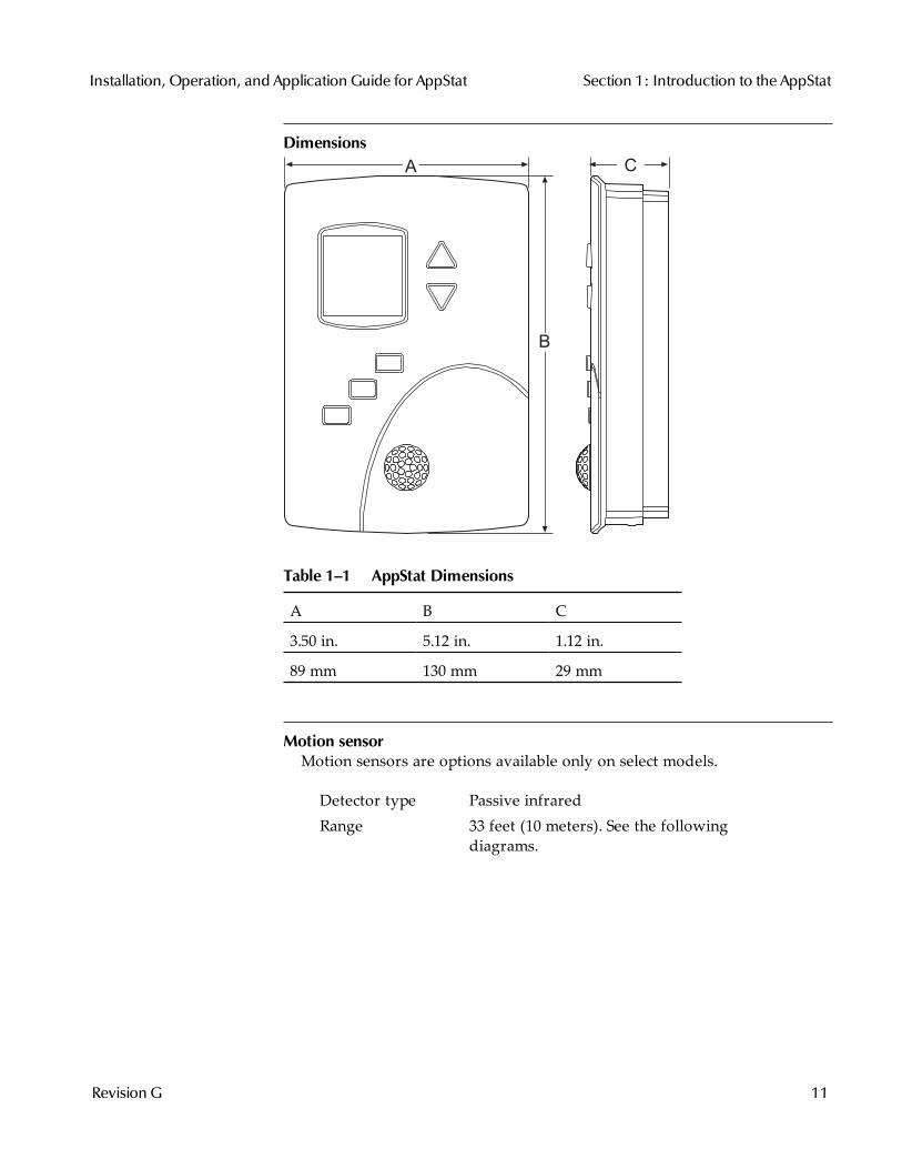
DimensionsA
B
C
A B C
3.50 in. 5.12 in. 1.12 in.
89 mm 130 mm 29 mm
Table 1–1 AppStat Dimensions
Motion sensorMotion sensors are options available only on select models.
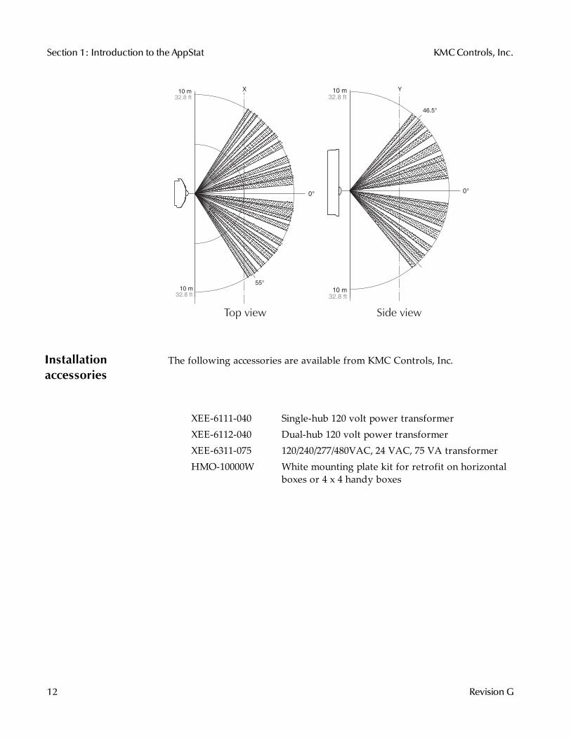
Detector type Passive infraredRange 33 feet (10 meters). See the following
diagrams.
Installation, Operation, and Application Guide for AppStat Section 1: Introduction to the AppStat
Revision G 11
10 m
32.8 ft
10 m
32.8 ft
0°
46.5°
Y
55°
10 m
32.8 ft
10 m
32.8 ft
X
0°
Side viewTop view
Installationaccessories
The following accessories are available from KMC Controls, Inc.
XEE-6111-040 Single-hub 120 volt power transformerXEE-6112-040 Dual-hub 120 volt power transformerXEE-6311-075 120/240/277/480VAC, 24 VAC, 75 VA transformerHMO-10000W White mounting plate kit for retrofit on horizontal
boxes or 4 x 4 handy boxes
Section 1: Introduction to the AppStat KMCControls, Inc.
12 Revision G
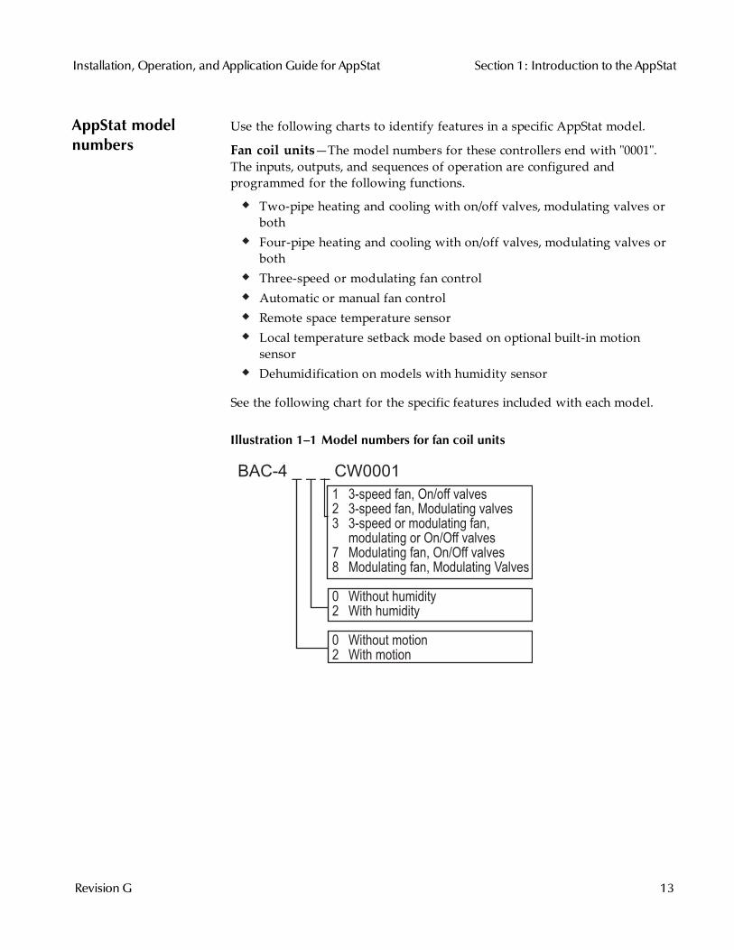
AppStat modelnumbers
Use the following charts to identify features in a specific AppStat model.
Fan coil units—The model numbers for these controllers end with "0001".The inputs, outputs, and sequences of operation are configured andprogrammed for the following functions.
Two-pipe heating and cooling with on/off valves, modulating valves orbothFour-pipe heating and cooling with on/off valves, modulating valves orbothThree-speed or modulating fan controlAutomatic or manual fan controlRemote space temperature sensorLocal temperature setback mode based on optional built-in motionsensorDehumidification on models with humidity sensor
See the following chart for the specific features included with each model.
Illustration 1–1 Model numbers for fan coil units
BAC-4 _ _ _ CW0001
1 3-speed fan, On/off valves2 3-speed fan, Modulating valves3 3-speed or modulating fan, modulating or On/Off valves7 Modulating fan, On/Off valves8 Modulating fan, Modulating Valves
0 Without humidity2 With humidity
0 Without motion2 With motion
Installation, Operation, and Application Guide for AppStat Section 1: Introduction to the AppStat
Revision G 13
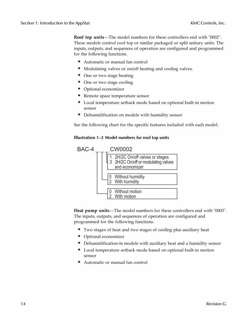
Roof top units—The model numbers for these controllers end with "0002".These models control roof top or similar packaged or split unitary units. Theinputs, outputs, and sequences of operation are configured and programmedfor the following functions.
Automatic or manual fan controlModulating valves or on/off heating and cooling valves.One or two stage heatingOne or two stage coolingOptional economizerRemote space temperature sensorLocal temperature setback mode based on optional built-in motionsensorDehumidification on models with humidity sensor
See the following chart for the specific features included with each model.
Illustration 1–2 Model numbers for roof top units
BAC-4 _ _ _ CW0002
1 2H/2C On/off valves or stages3 2H/2C On/off or modulating valves
and economizer
0 Without humidity2 With humidity
0 Without motion2 With motion
Heat pump units—The model numbers for these controllers end with "0003".The inputs, outputs, and sequences of operation are configured andprogrammed for the following functions.
Two stages of heat and two stages of cooling plus auxiliary heatOptional economizerDehumidification-in models with auxiliary heat and a humidity sensorLocal temperature setback mode based on optional built-in motionsensorAutomatic or manual fan control
Section 1: Introduction to the AppStat KMCControls, Inc.
14 Revision G
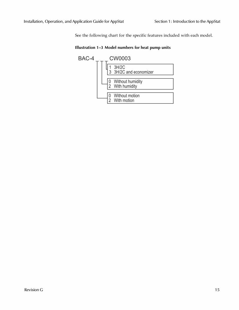
See the following chart for the specific features included with each model.
Illustration 1–3 Model numbers for heat pump units
BAC-4 _ _ _ CW0003
1 3H/2C3 3H/2C and economizer
0 Without humidity2 With humidity
0 Without motion2 With motion
Installation, Operation, and Application Guide for AppStat Section 1: Introduction to the AppStat
Revision G 15

Safetyconsiderations
KMC Controls, Inc. assumes the responsibility for providing you a safeproduct and safety guidelines during its use. Safety means protection to allindividuals who install, operate, and service the equipment as well asprotection of the equipment itself. To promote safety, we use hazard alertlabeling in this manual. Follow the associated guidelines to avoid hazards.
Danger
Danger represents themost severe hazard alert. Bodilyharm or death will occur if danger guidelines are notfollowed.
Warning
Warning represents hazards that could result in severeinjury or death.
Caution
Caution indicates potential personal injury, equipmentdamage, or property damage if instructions are not followed.
Note: Notes provide additional information that is important.
Tip: Provides programing tips and shortcuts that may save time.
Section 1: Introduction to the AppStat KMCControls, Inc.
16 Revision G
Sec t ion 2: Ins tal l ing the AppStat
This section provides important instructions and guidelines for installingthe AppStat. Carefully review this information before installation begins.
Installing the sensors includes the following topics that are covered in thissection.
Planning for motion sensing on page 17Mounting the AppStat on page 18Connecting inputs on page 20Connecting outputs on page 24Connecting power on page 28Maintenance on page 29
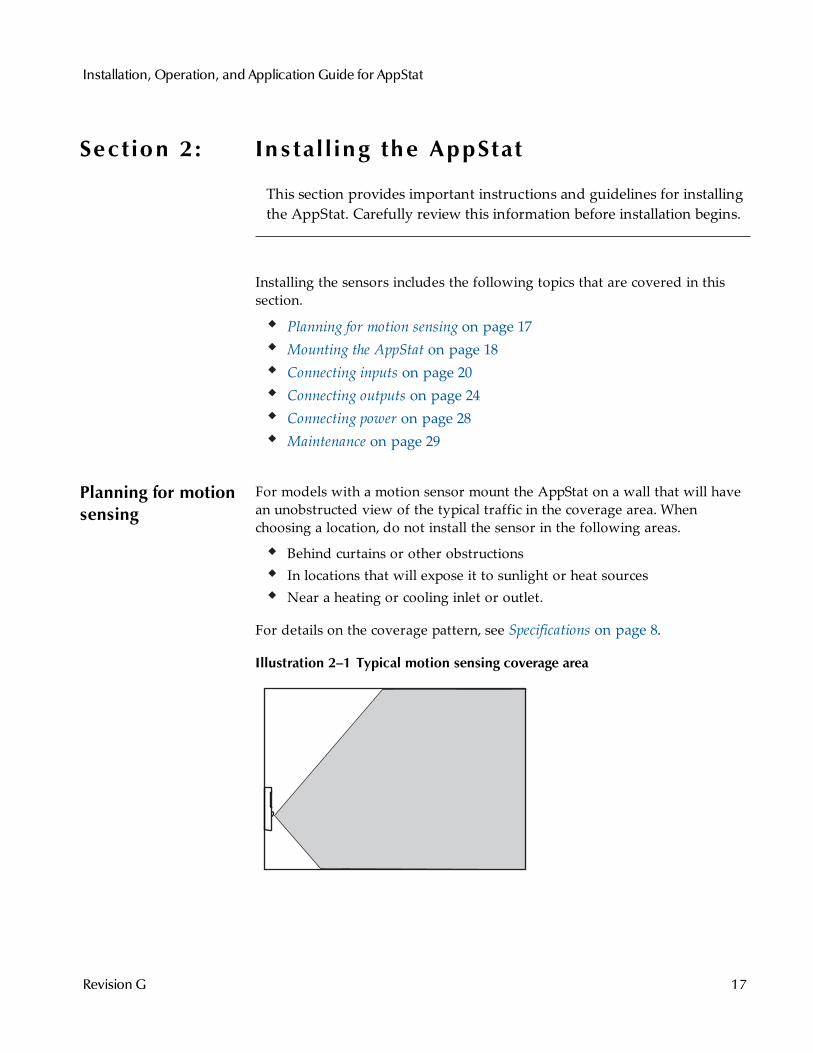
Planning for motionsensing
For models with a motion sensor mount the AppStat on a wall that will havean unobstructed view of the typical traffic in the coverage area. Whenchoosing a location, do not install the sensor in the following areas.
Behind curtains or other obstructionsIn locations that will expose it to sunlight or heat sourcesNear a heating or cooling inlet or outlet.
For details on the coverage pattern, see Specifications on page 8.
Illustration 2–1 Typical motion sensing coverage area
Installation, Operation, and Application Guide for AppStat
Revision G 17
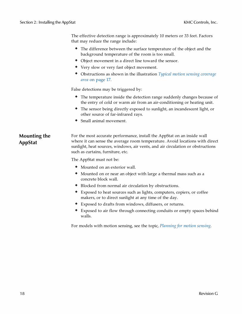
The effective detection range is approximately 10 meters or 33 feet. Factorsthat may reduce the range include:
The difference between the surface temperature of the object and thebackground temperature of the room is too small.Object movement in a direct line toward the sensor.Very slow or very fast object movement.Obstructions as shown in the illustration Typical motion sensing coveragearea on page 17.
False detections may be triggered by:
The temperature inside the detection range suddenly changes because ofthe entry of cold or warm air from an air-conditioning or heating unit.The sensor being directly exposed to sunlight, an incandescent light, orother source of far-infrared rays.Small animal movement.
Mounting theAppStat
For the most accurate performance, install the AppStat on an inside wallwhere it can sense the average room temperature. Avoid locations with directsunlight, heat sources, windows, air vents, and air circulation or obstructionssuch as curtains, furniture, etc.
The AppStat must not be:
Mounted on an exterior wall.Mounted on or near an object with large a thermal mass such as aconcrete block wall.Blocked from normal air circulation by obstructions.Exposed to heat sources such as lights, computers, copiers, or coffeemakers, or to direct sunlight at any time of the day.Exposed to drafts from windows, diffusers, or returns.Exposed to air flow through connecting conduits or empty spaces behindwalls.
For models with motion sensing, see the topic, Planning for motion sensing.
Section 2: Installing the AppStat KMCControls, Inc.
18 Revision G
Rough-in preparationComplete rough-in wiring at each location before mounting an AppStat. Thisincludes the following steps.
Install the supplied mounting base directly to a wall, a vertical electricalbox, or a box with a wall plate kit.Routing the connecting cable or cables from the AppStat to theequipment it is controlling.If required, install an appropriate wall plate kit.Block leaks and airflow from conduits with plumber’s putty or similarmaterial.If replacing an existing thermostat, label existing wires for referencewhen removing the existing thermostat.
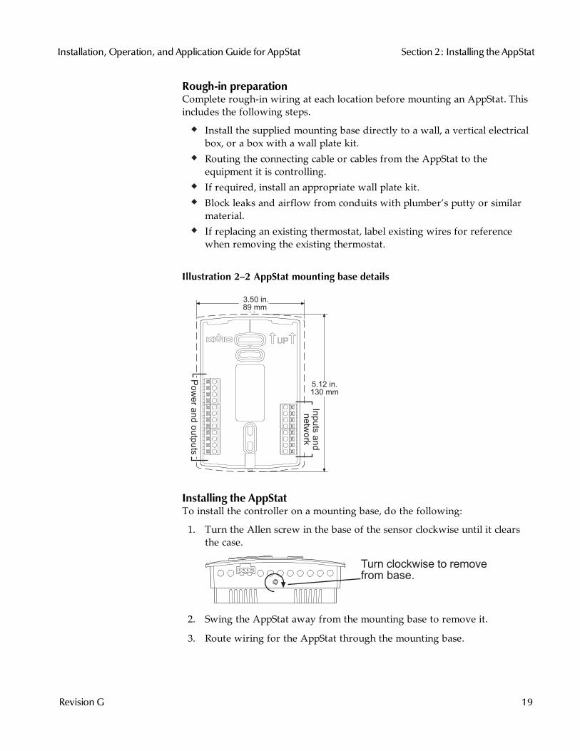
Illustration 2–2 AppStat mounting base details
A
5.12 in.130 mm
3.50 in. 89 mm
Inputs
and
netw
ork
Pow
er a
nd o
utp
uts
Installing the AppStatTo install the controller on a mounting base, do the following:
1. Turn the Allen screw in the base of the sensor clockwise until it clearsthe case.
Turn clockwise to remove
from base.
2. Swing the AppStat away from the mounting base to remove it.
3. Route wiring for the AppStat through the mounting base.
Installation, Operation, and Application Guide for AppStat Section 2: Installing the AppStat
Revision G 19
4. Position the base with the embossed UP toward the ceiling and fasten itdirectly to a vertical 2 x 4 inch electrical box. For horizontal boxes or4 x 4 applications, use a wall plate kit. See Installation accessories on page12 for part numbers.
5. Connect the wires for the AppStat to the terminals in the mounting base.
6. Place the top of the sensor over the top of the mounting base and swingit down over the Allen screw bracket. Be careful not to pinch any wiring.
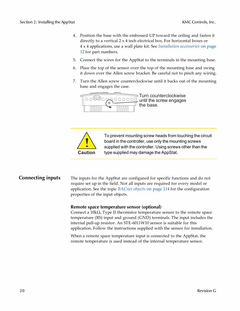
7. Turn the Allen screw counterclockwise until it backs out of the mountingbase and engages the case.
Turn counterclockwiseuntil the screw engagesthe base.
Caution
To prevent mounting screw heads from touching the circuitboard in the controller, use only themounting screwssupplied with the controller. Using screws other than thetype suppliedmay damage the AppStat.
Connecting inputs The inputs for the AppStat are configured for specific functions and do notrequire set up in the field. Not all inputs are required for every model orapplication. See the topic BACnet objects on page 114 for the configurationproperties of the input objects.
Remote space temperature sensor (optional)Connect a 10kΩ, Type II thermistor temperature sensor to the remote spacetemperature (RS) input and ground (GND) terminals. The input includes theinternal pull-up resistor. An STE-6011W10 sensor is suitable for thisapplication. Follow the instructions supplied with the sensor for installation.
When a remote space temperature input is connected to the AppStat, theremote temperature is used instead of the internal temperature sensor.
Section 2: Installing the AppStat KMCControls, Inc.
20 Revision G
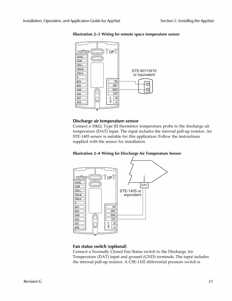
Illustration 2–3 Wiring for remote space temperature sensor
STE-6011W10or equivalent
MS/T
P
+B
A
RS
WST
GND
DAT
COM
FAN-L
FAN-M
FAN-H
R
BO4
BO5
GND
AO6
AO8
AO7
24VAC
Discharge air temperature sensorConnect a 10kΩ, Type III thermistor temperature probe to the discharge airtemperature (DAT) input. The input includes the internal pull-up resistor. AnSTE-1405 sensor is suitable for this application. Follow the instructionssupplied with the sensor for installation.
Illustration 2–4 Wiring for Discharge Air Temperature Sensor
STE-1405 orequivalent
DAT
MS/T
P
+B
A
RS
WST
GND
DAT
COM
FAN-L
FAN-M
FAN-H
R
BO4
BO5
GND
AO6
AO8
AO7
24VAC
Fan status switch (optional)Connect a Normally Closed Fan Status switch to the Discharge AirTemperature (DAT) input and ground (GND) terminals. The input includesthe internal pull-up resistor. A CSE-1102 differential pressure switch is
Installation, Operation, and Application Guide for AppStat Section 2: Installing the AppStat
Revision G 21
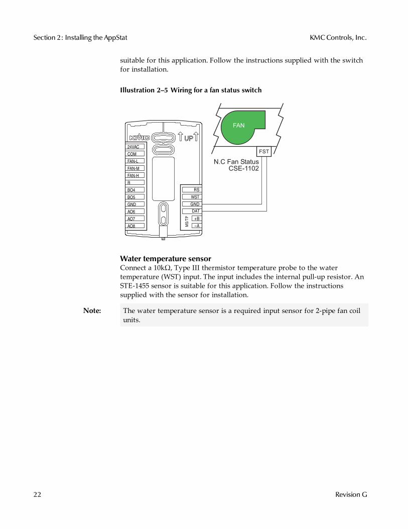
suitable for this application. Follow the instructions supplied with the switchfor installation.
Illustration 2–5 Wiring for a fan status switch
FST
N.C Fan Status
CSE-1102
FAN
MS/T
P
+B
A
RS
WST
GND
DAT
COM
FAN-L
FAN-M
FAN-H
R
BO4
BO5
GND
AO6
AO8
AO7
24VAC
Water temperature sensorConnect a 10kΩ, Type III thermistor temperature probe to the watertemperature (WST) input. The input includes the internal pull-up resistor. AnSTE-1455 sensor is suitable for this application. Follow the instructionssupplied with the sensor for installation.
Note: The water temperature sensor is a required input sensor for 2-pipe fan coilunits.
Section 2: Installing the AppStat KMCControls, Inc.
22 Revision G

Illustration 2–6 Wiring for a water temperature sensor
STE-1455 orequivalent
WST
MS/T
P
+B
A
RS
WST
GND
DAT
COM
FAN-L
FAN-M
FAN-H
R
BO4
BO5
GND
AO6
AO8
AO7
24VAC
Outside air temperatureConnect a 10kΩ, Type III thermistor temperature probe to the outside airtemperature (OAT) input. The input includes the internal pull-up resistor. AnSTE-1451 sensor is suitable for this application. Follow the instructionssupplied with the sensor for installation.
Illustration 2–7 Wiring for an outside air temperature sensor
STE-1451 orequivalent
MS/T
P
+B
A
RS
OAT
GND
DAT
ECON
G
Y1
Y2
RC
W1
W2
RH
AO6
AO7
COM
24VAC
OAT
Installation, Operation, and Application Guide for AppStat Section 2: Installing the AppStat
Revision G 23
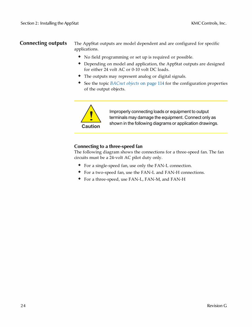
Connecting outputs The AppStat outputs are model dependent and are configured for specificapplications.
No field programming or set up is required or possible.Depending on model and application, the AppStat outputs are designedfor either 24 volt AC or 0-10 volt DC loads.The outputs may represent analog or digital signals.See the topic BACnet objects on page 114 for the configuration propertiesof the output objects.
Caution
Improperly connecting loads or equipment to outputterminalsmay damage the equipment. Connect only asshown in the following diagrams or application drawings.
Connecting to a three-speed fanThe following diagram shows the connections for a three-speed fan. The fancircuits must be a 24-volt AC pilot duty only.
For a single-speed fan, use only the FAN-L connection.For a two-speed fan, use the FAN-L and FAN-H connections.For a three-speed, use FAN-L, FAN-M, and FAN-H
Section 2: Installing the AppStat KMCControls, Inc.
24 Revision G
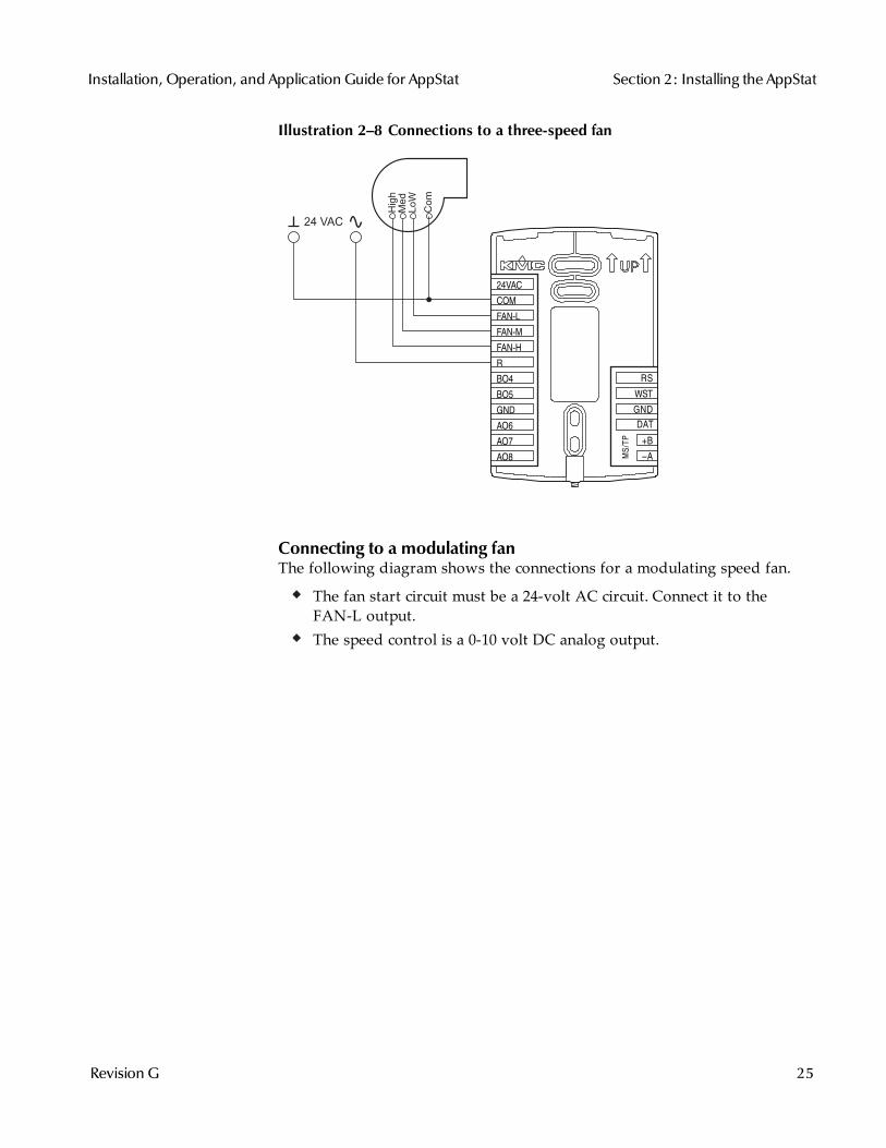
Illustration 2–8 Connections to a three-speed fan
Hig
hM
ed
Lo
W
Co
m
24 VAC
MS/T
P
+B
A
RS
WST
GND
DAT
COM
FAN-L
FAN-M
FAN-H
R
BO4
BO5
GND
AO6
AO8
AO7
24VAC
Connecting to a modulating fanThe following diagram shows the connections for a modulating speed fan.
The fan start circuit must be a 24-volt AC circuit. Connect it to theFAN-L output.The speed control is a 0-10 volt DC analog output.
Installation, Operation, and Application Guide for AppStat Section 2: Installing the AppStat
Revision G 25

Illustration 2–9 Connections for a modulating fan
Sp
ee
d
Sta
rtC
om
24 VAC
MS/T
P
+B
A
RS
WST
GND
DAT
COM
FAN-L
FAN-M
FAN-H
R
BO4
BO5
GND
AO6
AO8
AO7
24VAC
Connecting on/off valvesThe following diagram shows the connections on/off valves.
The valves are activated by 24-volts AC.The outputs are 24-volt relays.
Illustration 2–10 Connections to on/off valves
Cooling Heating
24 VAC
MS/T
P
+B
A
RS
WST
GND
DAT
COM
FAN-L
FAN-M
FAN-H
R
BO4
BO5
GND
AO6
AO8
AO7
24VAC
Section 2: Installing the AppStat KMCControls, Inc.
26 Revision G

Connecting to modulating valvesThe following diagram shows the connections for a modulating mixingvalves. The valve control signal is a 0-10 volt analog output.
Illustration 2–11 Modulating heating and cooling valves
0-10VDC
0-10VDC
Cooling Heating24 VAC
MS/T
P
+B
A
RS
WST
GND
DAT
COM
FAN-L
FAN-M
FAN-H
R
BO4
BO5
GND
AO6
AO8
AO7
24VAC
Installation, Operation, and Application Guide for AppStat Section 2: Installing the AppStat
Revision G 27
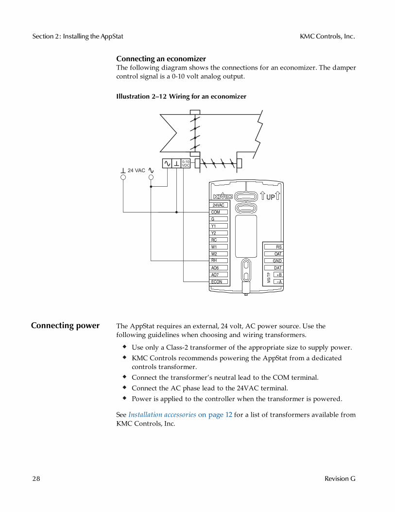
Connecting an economizerThe following diagram shows the connections for an economizer. The dampercontrol signal is a 0-10 volt analog output.
Illustration 2–12 Wiring for an economizer
0-10
VDC
24 VAC
MS/T
P
+B
A
RS
OAT
GND
DAT
ECON
G
Y1
Y2
RC
W1
W2
RH
AO6
AO7
COM
24VAC
Connecting power The AppStat requires an external, 24 volt, AC power source. Use thefollowing guidelines when choosing and wiring transformers.
Use only a Class-2 transformer of the appropriate size to supply power.KMC Controls recommends powering the AppStat from a dedicatedcontrols transformer.Connect the transformer’s neutral lead to the COM terminal.Connect the AC phase lead to the 24VAC terminal.Power is applied to the controller when the transformer is powered.
See Installation accessories on page 12 for a list of transformers available fromKMC Controls, Inc.
Section 2: Installing the AppStat KMCControls, Inc.
28 Revision G
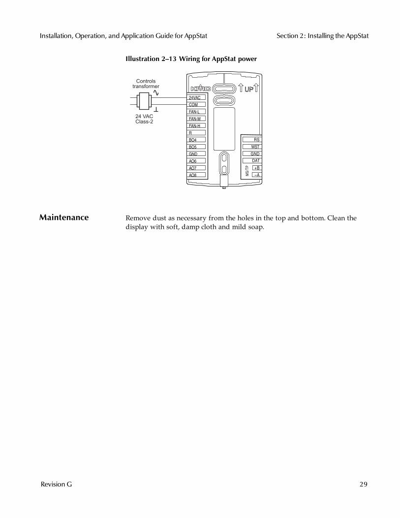
Illustration 2–13 Wiring for AppStat power
24 VAC
Class-2
Controls
transformer
MS/T
P
+B
A
RS
WST
GND
DAT
COM
FAN-L
FAN-M
FAN-H
R
BO4
BO5
GND
AO6
AO8
AO7
24VAC
Maintenance Remove dust as necessary from the holes in the top and bottom. Clean thedisplay with soft, damp cloth and mild soap.
Installation, Operation, and Application Guide for AppStat Section 2: Installing the AppStat
Revision G 29
Section 2: Installing the AppStat KMCControls, Inc.
30 Revision G
Sec t ion 3: Use r func t ions
This section covers topics for the end user in a facility.
AppStat user functions are limited to changing the following functions.
Active temperature setpointsFan operationChanging between heating and coolingOverride scheduled occupancy or occupancy based on the schedule inthe AppStat.Change the display between Fahrenheit and Celsius
Operating theAppStat
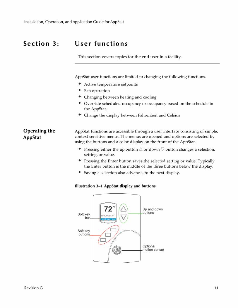
AppStat functions are accessible through a user interface consisting of simple,context sensitive menus. The menus are opened and options are selected byusing the buttons and a color display on the front of the AppStat.
Pressing either the up button or down button changes a selection,setting, or value.Pressing the Enter button saves the selected setting or value. Typicallythe Enter button is the middle of the three buttons below the display.Saving a selection also advances to the next display.
Illustration 3–1 AppStat display and buttons
COOLING SETPT
Up and downbuttons
Soft keybuttons
Soft keybar
Optionalmotion sensor
72F°
AUTO AUTODoneEnterCncl
Installation, Operation, and Application Guide for AppStat
Revision G 31
The three buttons below the display are defined by labels in the soft key bar.Typically the buttons are designated for the following functions.
Back—Returns to the previous menu.Cncl—Cancels current changes.Done—Push this button at any point while entering a value. For example,if you have entered the first two digits of a password and the remainingtwo digits are correct, pushing Done completes the entry of thepassword.Enter—Pushing this button enters the selection and advances to the nextstep.Exit—Returns to temperature display.
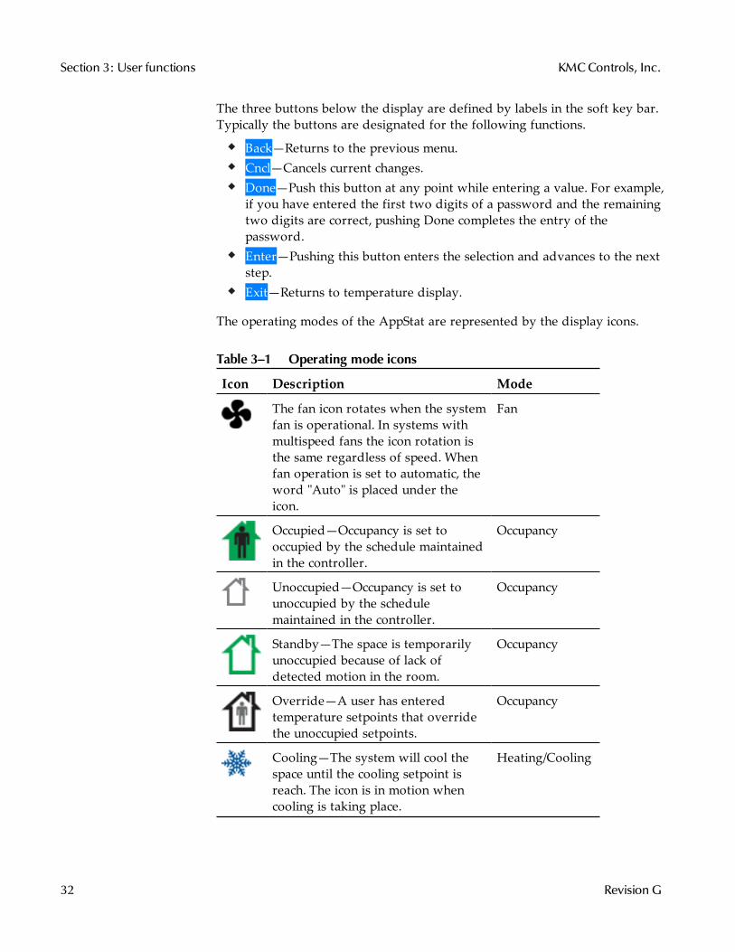
The operating modes of the AppStat are represented by the display icons.
Icon Description Mode
The fan icon rotates when the systemfan is operational. In systems withmultispeed fans the icon rotation isthe same regardless of speed. Whenfan operation is set to automatic, theword "Auto" is placed under theicon.
Fan
Occupied—Occupancy is set tooccupied by the schedule maintainedin the controller.
Occupancy
Unoccupied—Occupancy is set tounoccupied by the schedulemaintained in the controller.
Occupancy
Standby—The space is temporarilyunoccupied because of lack ofdetected motion in the room.
Occupancy
Override—A user has enteredtemperature setpoints that overridethe unoccupied setpoints.
Occupancy
Cooling—The system will cool thespace until the cooling setpoint isreach. The icon is in motion whencooling is taking place.
Heating/Cooling
Table 3–1 Operating mode icons
Section 3: User functions KMCControls, Inc.
32 Revision G

Icon Description Mode
Heating—The system will heat thespace until the heating setpoint isreached. The icon is in motion whenheating is taking place.
Heating/Cooling
Off System is off Heating/Cooling
Dehumidification—Duringdehumidification the system willheat and cool at the same time toremove humidity and maintain theactive temperature setpoint. The iconis in motion while dehumidificationis taking place.
Heating/Cooling
Operating mode icons (continued)
Installation, Operation, and Application Guide for AppStat Section 3: User functions
Revision G 33
Entering a userpassword
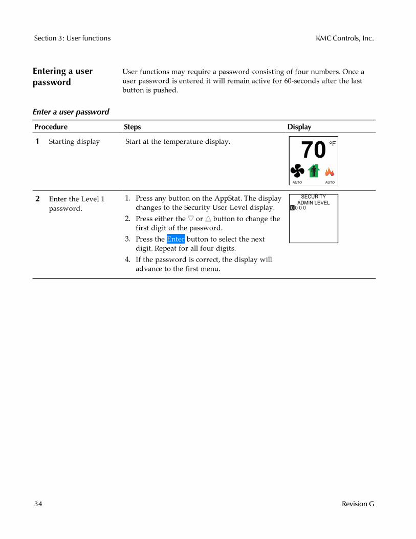
User functions may require a password consisting of four numbers. Once auser password is entered it will remain active for 60-seconds after the lastbutton is pushed.
Procedure Steps Display
1 Starting display Start at the temperature display. F°
70
AUTO AUTO
2 Enter the Level 1password.
1. Press any button on the AppStat. The displaychanges to the Security User Level display.
2. Press either the or button to change thefirst digit of the password.
3. Press the Enter button to select the nextdigit. Repeat for all four digits.
4. If the password is correct, the display willadvance to the first menu.
SECURITY
ADMIN LEVEL
0 0 0 0
Enter a user password
Section 3: User functions KMCControls, Inc.
34 Revision G
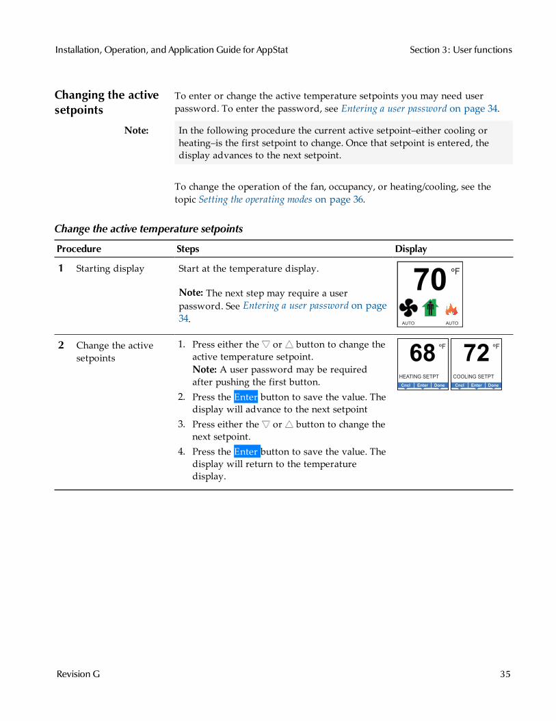
Changing the activesetpoints
To enter or change the active temperature setpoints you may need userpassword. To enter the password, see Entering a user password on page 34.
Note: In the following procedure the current active setpoint–either cooling orheating–is the first setpoint to change. Once that setpoint is entered, thedisplay advances to the next setpoint.
To change the operation of the fan, occupancy, or heating/cooling, see thetopic Setting the operating modes on page 36.
Procedure Steps Display
1 Starting display Start at the temperature display.
Note: The next step may require a userpassword. See Entering a user password on page34.
F°
70
AUTO AUTO
2 Change the activesetpoints
1. Press either the or button to change theactive temperature setpoint.Note: A user password may be requiredafter pushing the first button.
2. Press the Enter button to save the value. Thedisplay will advance to the next setpoint
3. Press either the or button to change thenext setpoint.
4. Press the Enter button to save the value. Thedisplay will return to the temperaturedisplay.
F°
68
HEATING SETPT
DoneEnterCncl
F°
72
COOLING SETPT
DoneEnterCncl
Change the active temperature setpoints
Installation, Operation, and Application Guide for AppStat Section 3: User functions
Revision G 35

Setting theoperating modes
The operating modes set the following functions.
Fan operationChanging between heating and coolingOverride scheduled occupancy or occupancy that has been set by aschedule.Change the display units from Fahrenheit to Celsius.
To change the occupied temperature setpoints, see the topic Changing theactive setpoints on page 35.
Procedure Steps Display
1 Starting display Start at the temperature display.
Note: The following procedures may require auser password. See Entering a user password onpage 34.
F°
70
AUTO AUTO
2 Change the heatingor cooling mode.
1. Push the button under the heating/coolingicon.Note: If a user password has previously beenentered or if the AppStat has not been set upwith a user password, entering a password isnot required.
2. Press either the or button to select theheating/cooling mode. The mode may be oneof the following.Emergency—(Option) Turns on the auxiliaryheating in a heat pump unit.Heat—The system will only heat the space.Cool—The system will only cool the space.Auto—The system will switch betweenheating and cooling.Off—The system is turned off.
3. Press the Enter button to save the setting.The display returns to the temperaturedisplay.
EnterCncl
MODE: HEAT
COOL
AUTO
OFF
EnterCncl
MODE: EMERGENCY
HEAT
COOL
AUTO
OFF
Heating/cooling icons
Set the operating modes
Section 3: User functions KMCControls, Inc.
36 Revision G
Procedure Steps Display
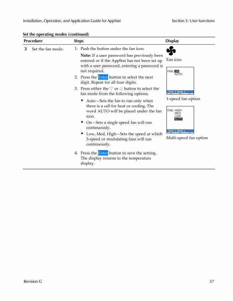
3 Set the fan mode. 1. Push the button under the fan icon.Note: If a user password has previously beenentered or if the AppStat has not been set upwith a user password, entering a password isnot required.
2. Press the Enter button to select the nextdigit. Repeat for all four digits.
3. Press either the or button to select thefan mode from the following options.
Auto—Sets the fan to run only whenthere is a call for heat or cooling. Theword AUTO will be placed under the fanicon.On—Sets a single speed fan will runcontinuously.Low, Med, High—Sets the speed at which3-speed or modulating fans will runcontinuously.
4. Press the Enter button to save the setting.The display returns to the temperaturedisplay.
Fan icon
EnterCncl
FAN: ON
AUTO
1-speed fan option
EnterCncl
FAN: HIGH
MED
LOW
AUTO
Multi-speed fan option
Set the operating modes (continued)
Installation, Operation, and Application Guide for AppStat Section 3: User functions
Revision G 37
Procedure Steps Display
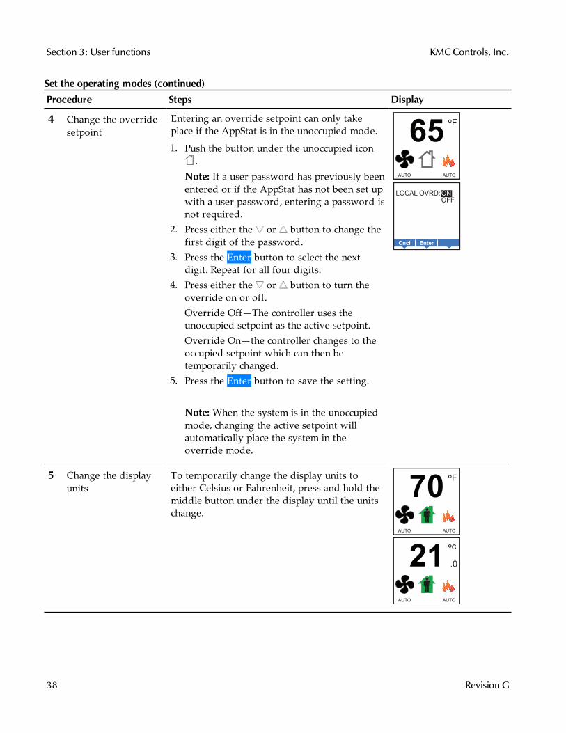
4 Change the overridesetpoint
Entering an override setpoint can only takeplace if the AppStat is in the unoccupied mode.
1. Push the button under the unoccupied icon.
Note: If a user password has previously beenentered or if the AppStat has not been set upwith a user password, entering a password isnot required.
2. Press either the or button to change thefirst digit of the password.
3. Press the Enter button to select the nextdigit. Repeat for all four digits.
4. Press either the or button to turn theoverride on or off.Override Off—The controller uses theunoccupied setpoint as the active setpoint.Override On—the controller changes to theoccupied setpoint which can then betemporarily changed.
5. Press the Enter button to save the setting.
Note: When the system is in the unoccupiedmode, changing the active setpoint willautomatically place the system in theoverride mode.
F°
65
AUTO AUTO
EnterCncl
LOCAL OVRD: ON
OFF
5 Change the displayunits
To temporarily change the display units toeither Celsius or Fahrenheit, press and hold themiddle button under the display until the unitschange.
F°
70
AUTO AUTO
°
21c
.0
AUTO AUTO
Set the operating modes (continued)
Section 3: User functions KMCControls, Inc.
38 Revision G
Sec t ion 4: Commiss ion ing func t ions
This topics in this section are advanced topics for control technicians andengineers. These topic cover procedures for the initial AppStat setup.
The AppStat commissioning functions are values and settings that are enteredduring the installation and commissioning of a controller and the equipmentit is controlling. Typically these functions do not change after the installationand commissioning process.
To set up the commissioning functions, you will need the followinginformation.
Information about the equipmentThe sequence of operation for the equipmentThe building automation system plans for controllers that are part of anetwork.
Users may change the occupied heating and cooling setpoints withoutaccessing the commissioning functions. This procedure is covered in the topicUser functions on page 31.
Note: The instructions for the AppStat commissioning functions cover all of thefunctions that can be set in the controller. Not all functions are available onevery model of controller. Consult the installation and operation manualsupplied with the controller to verify the application programming in theAppStat.
Installation, Operation, and Application Guide for AppStat
Revision G 39
Enter thecommissioningmode
For access to the commissioning functions you will need to know Password 2.
If the controller has not been previously set up, no password is required.A new Password 2 can be entered in the advanced commissioningfunctions. See the topic Advanced options on page 60.
Procedure Steps Display
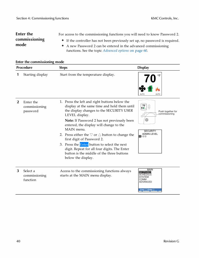
1 Starting display Start from the temperature display. F°
70
AUTO AUTO
2 Enter thecommissioningpassword
1. Press the left and right buttons below thedisplay at the same time and hold them untilthe display changes to the SECURITY USERLEVEL display.Note: If Password 2 has not previously beenentered, the display will change to theMAIN menu.
2. Press either the or button to change thefirst digit of Password 2.
3. Press the Enter button to select the nextdigit. Repeat for all four digits. The Enterbutton is the middle of the three buttonsbelow the display.
Push together forcommissioning
AUTO AUTO
70F°
SECURITY
ADMIN LEVEL
0 0 0 0
3 Select acommissioningfunction
Access to the commissioning functions alwaysstarts at the MAIN menu display.
EnterCncl
MAIN
SETPOINT
SCHEDULE
SYSTEM
COMM
ADVANCED
Enter the commissioning mode
Section 4: Commissioning functions KMCControls, Inc.
40 Revision G

Setting thecommissioningsetpoints
The commissioning setpoints set the operational setpoints and limits for theAppStat. The functions of the setpoints and how they are used are describe inthe topic Room temperature setpoints on page 66. Setting commissioningsetpoints requires entering Password 2 which is described in the topic Enterthe commissioning mode on page 40.
Note: Not all setpoints in the following procedure are applicable to all models ofAppStat. Those setpoints are marked as (optional).
Procedure Steps Display
1 Starting display 1. Start at the temperature display.
2. Enter Password 2. The display changes to theMAIN menu display.
F°
70
AUTO AUTO
SECURITY
ADMIN LEVEL
0 0 0 0
2 Choose and set thesetpoints.
1. From the MAIN menu , press either the orbutton to select SETPOINTS.
2. Press Enter. The SETPOINT menu opens3. Choose and set each of the followingsetpoints. EnterCncl
MAIN
SETPOINT
SCHEDULE
SYSTEM
COMM
ADVANCED
Procedure to set the commissioning setpoints
Installation, Operation, and Application Guide for AppStat Section 4: Commissioning functions
Revision G 41
Procedure Steps Display
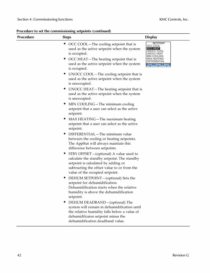
OCC COOL—The cooling setpoint that isused as the active setpoint when the systemis occupied.OCC HEAT—The heating setpoint that isused as the active setpoint when the systemis occupied.UNOCC COOL—The cooling setpoint that isused as the active setpoint when the systemis unoccupied.UNOCC HEAT—The heating setpoint that isused as the active setpoint when the systemis unoccupied.MIN COOLING—The minimum coolingsetpoint that a user can select as the activesetpoint.MAX HEATING—The maximum heatingsetpoint that a user can select as the activesetpoint.DIFFERENTIAL—The minimum valuebetween the cooling or heating setpoints.The AppStat will always maintain thisdifference between setpoints.STBY OFFSET—(optional) A value used tocalculate the standby setpoint. The standbysetpoint is calculated by adding orsubtracting the offset value to or from thevalue of the occupied setpoint.DEHUM SETPOINT—(optional) Sets thesetpoint for dehumidification.Dehumidification starts when the relativehumidity is above the dehumidificationsetpoint.DEHUM DEADBAND—(optional) Thesystem will remain in dehumidification untilthe relative humidity falls below a value ofdehumidficaion setpoint minus thedehumidification deadband value.
BackEnterCncl
SETPOINT
OCC COOL
OCC HEAT
UNOCC COOL
UNOCC HEAT
MIN COOLING
MAX HEATING
DIFFERENTIAL
Procedure to set the commissioning setpoints (continued)
Section 4: Commissioning functions KMCControls, Inc.
42 Revision G
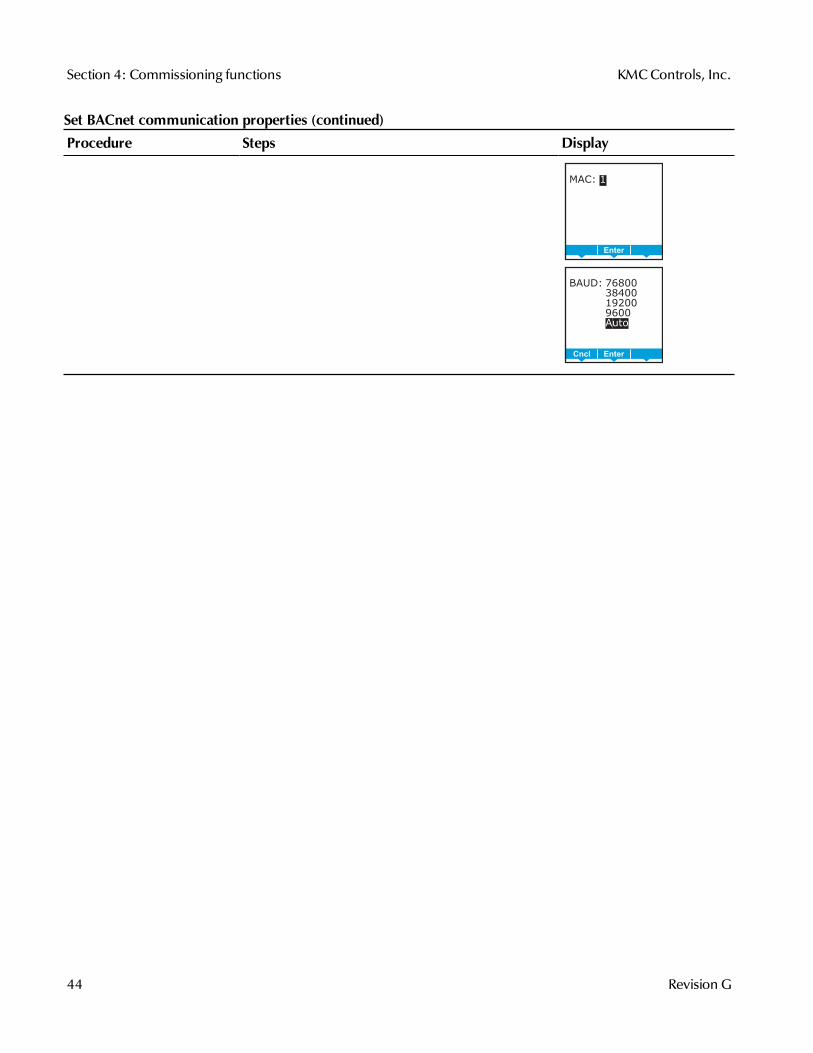
Set upcommunications
Setting BACnet communications properties is required only if the AppStat isintegrated into a network with other BACnet controllers. Entering thecommunications properties requires entering Password 2 which is describedin the topic Enter the commissioning mode on page 40.
See the topic Connecting to an MS/TP network on page 121 for networkwiring details.
Procedure Steps Display
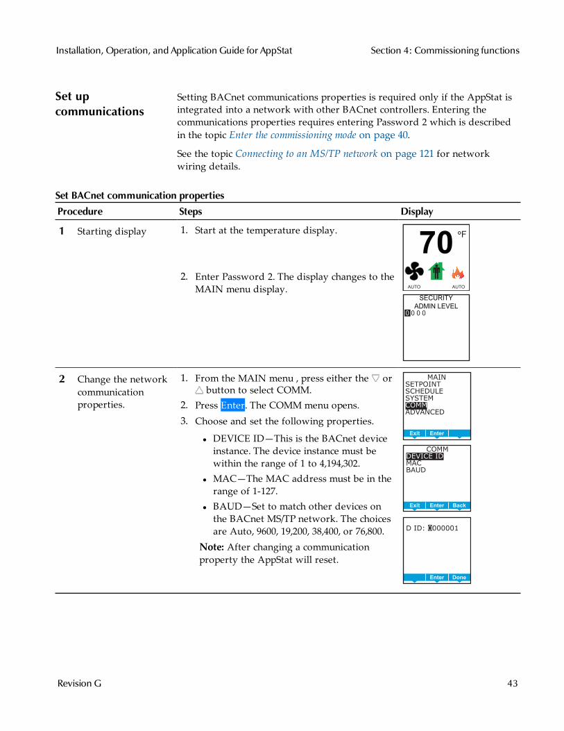
1 Starting display 1. Start at the temperature display.
2. Enter Password 2. The display changes to theMAIN menu display.
F°
70
AUTO AUTO
SECURITY
ADMIN LEVEL
0 0 0 0
2 Change the networkcommunicationproperties.
1. From the MAIN menu , press either the orbutton to select COMM.
2. Press Enter. The COMM menu opens.3. Choose and set the following properties.
l DEVICE ID—This is the BACnet deviceinstance. The device instance must bewithin the range of 1 to 4,194,302.
l MAC—The MAC address must be in therange of 1-127.
l BAUD—Set to match other devices onthe BACnet MS/TP network. The choicesare Auto, 9600, 19,200, 38,400, or 76,800.
Note: After changing a communicationproperty the AppStat will reset.
MAIN
SETPOINT
SCHEDULE
SYSTEM
COMM
ADVANCED
BackEnterExit
COMM
DEVICE ID
MAC
BAUD
BackEnterExit
D ID: 0000001
DoneEnterEnter
Set BACnet communication properties
Installation, Operation, and Application Guide for AppStat Section 4: Commissioning functions
Revision G 43
Procedure Steps Display
MAC: 1
DoneEnterEnter
BAUD: 76800
38400
19200
9600
Auto
DoneEnterCncl
Set BACnet communication properties (continued)
Section 4: Commissioning functions KMCControls, Inc.
44 Revision G
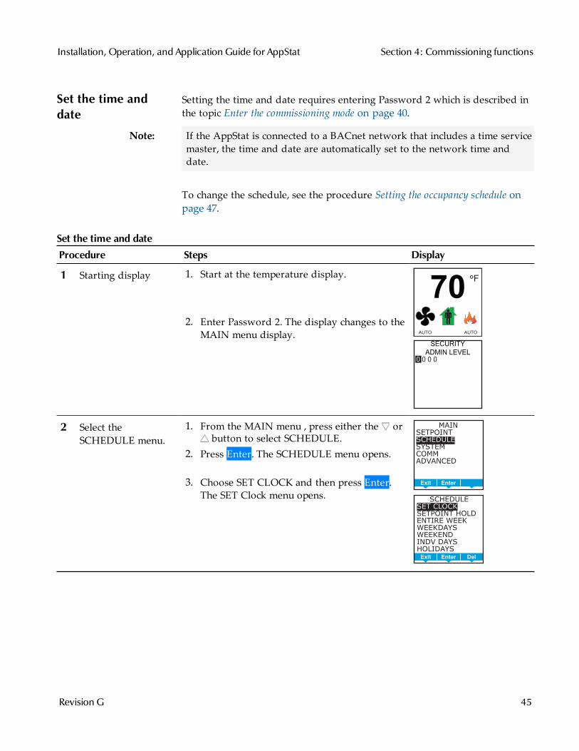
Set the time anddate
Setting the time and date requires entering Password 2 which is described inthe topic Enter the commissioning mode on page 40.
Note: If the AppStat is connected to a BACnet network that includes a time servicemaster, the time and date are automatically set to the network time anddate.
To change the schedule, see the procedure Setting the occupancy schedule onpage 47.
Procedure Steps Display
1 Starting display 1. Start at the temperature display.
2. Enter Password 2. The display changes to theMAIN menu display.
F°
70
AUTO AUTO
SECURITY
ADMIN LEVEL
0 0 0 0
2 Select theSCHEDULE menu.
1. From the MAIN menu , press either the orbutton to select SCHEDULE.
2. Press Enter. The SCHEDULE menu opens.
3. Choose SET CLOCK and then press Enter.The SET Clock menu opens.
MAIN
SETPOINT
SCHEDULE
SYSTEM
COMM
ADVANCED
BackEnterExit
SCHEDULE
SET CLOCK
SETPOINT HOLD
ENTIRE WEEK
WEEKDAYS
WEEKEND
INDV DAYS
HOLIDAYS
DelEnterExit
Set the time and date
Installation, Operation, and Application Guide for AppStat Section 4: Commissioning functions
Revision G 45
Procedure Steps Display
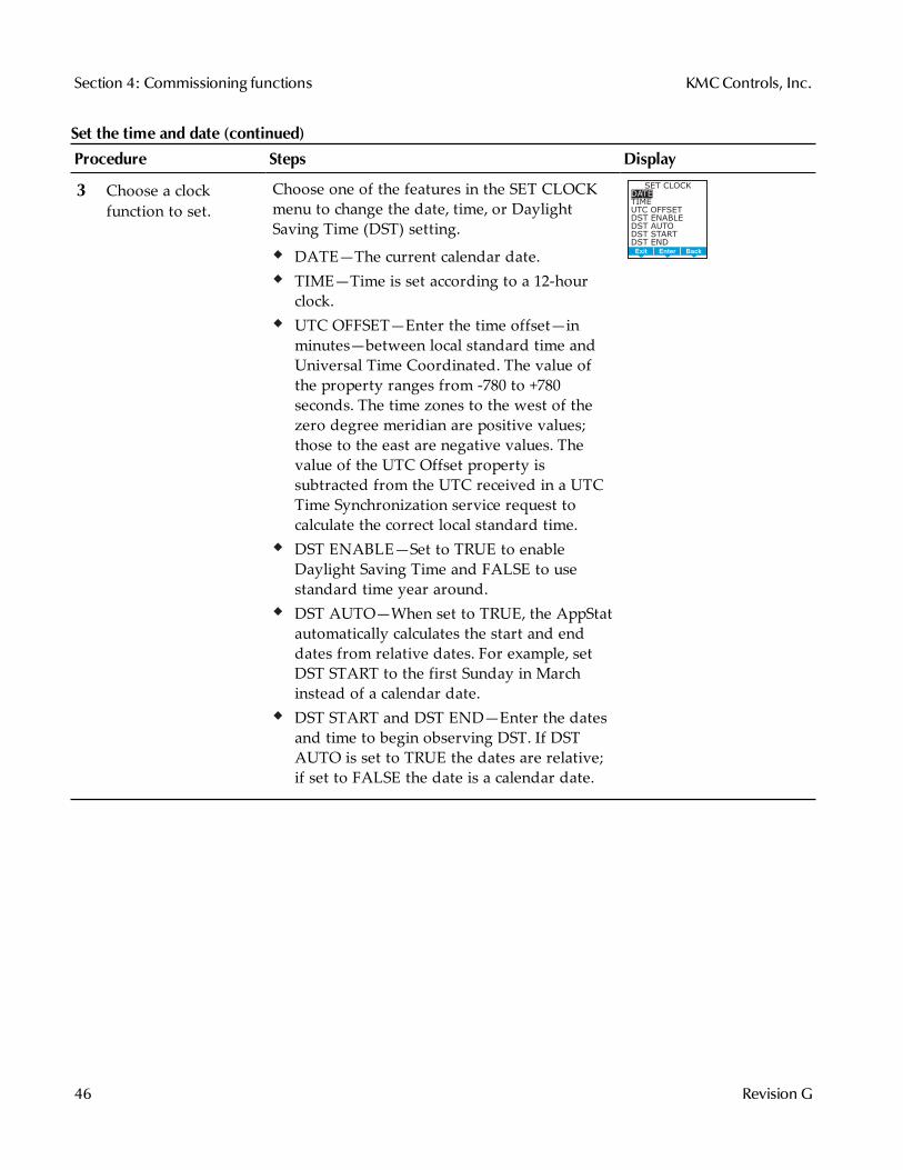
3 Choose a clockfunction to set.
Choose one of the features in the SET CLOCKmenu to change the date, time, or DaylightSaving Time (DST) setting.
DATE—The current calendar date.TIME—Time is set according to a 12-hourclock.UTC OFFSET—Enter the time offset—inminutes—between local standard time andUniversal Time Coordinated. The value ofthe property ranges from -780 to +780seconds. The time zones to the west of thezero degree meridian are positive values;those to the east are negative values. Thevalue of the UTC Offset property issubtracted from the UTC received in a UTCTime Synchronization service request tocalculate the correct local standard time.DST ENABLE—Set to TRUE to enableDaylight Saving Time and FALSE to usestandard time year around.DST AUTO—When set to TRUE, the AppStatautomatically calculates the start and enddates from relative dates. For example, setDST START to the first Sunday in Marchinstead of a calendar date.DST START and DST END—Enter the datesand time to begin observing DST. If DSTAUTO is set to TRUE the dates are relative;if set to FALSE the date is a calendar date.
SET CLOCK
DATE
TIME
UTC OFFSET
DST ENABLE
DST AUTO
DST START
DST END
BackEnterExit
Set the time and date (continued)
Section 4: Commissioning functions KMCControls, Inc.
46 Revision G
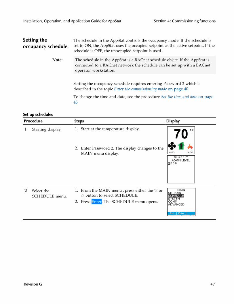
Setting theoccupancy schedule
The schedule in the AppStat controls the occupancy mode. If the schedule isset to ON, the AppStat uses the occupied setpoint as the active setpoint. If theschedule is OFF, the unoccupied setpoint is used.
Note: The schedule in the AppStat is a BACnet schedule object. If the AppStat isconnected to a BACnet network the schedule can be set up with a BACnetoperator workstation.
Setting the occupancy schedule requires entering Password 2 which isdescribed in the topic Enter the commissioning mode on page 40.
To change the time and date, see the procedure Set the time and date on page45.
Procedure Steps Display
1 Starting display 1. Start at the temperature display.
2. Enter Password 2. The display changes to theMAIN menu display.
F°
70
AUTO AUTO
SECURITY
ADMIN LEVEL
0 0 0 0
2 Select theSCHEDULE menu.
1. From the MAIN menu , press either the orbutton to select SCHEDULE.
2. Press Enter. The SCHEDULE menu opens.
MAIN
SETPOINT
SCHEDULE
SYSTEM
COMM
ADVANCED
BackEnterExit
Set up schedules
Installation, Operation, and Application Guide for AppStat Section 4: Commissioning functions
Revision G 47
Procedure Steps Display
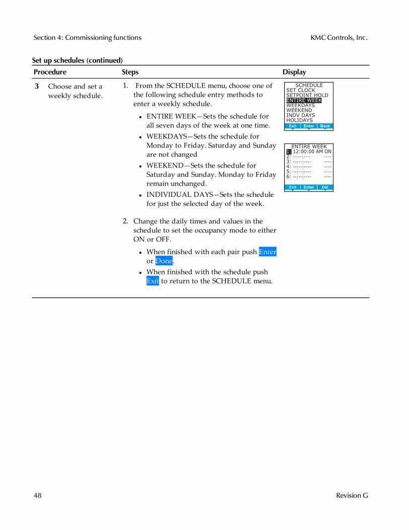
3 Choose and set aweekly schedule.
1. From the SCHEDULE menu, choose one ofthe following schedule entry methods toenter a weekly schedule.
l ENTIRE WEEK—Sets the schedule forall seven days of the week at one time.
l WEEKDAYS—Sets the schedule forMonday to Friday. Saturday and Sundayare not changed
l WEEKEND—Sets the schedule forSaturday and Sunday. Monday to Fridayremain unchanged.
l INDIVIDUAL DAYS—Sets the schedulefor just the selected day of the week.
2. Change the daily times and values in theschedule to set the occupancy mode to eitherON or OFF.
l When finished with each pair push Enteror Done.
l When finished with the schedule pushExit to return to the SCHEDULE menu.
SCHEDULE
SET CLOCK
SETPOINT HOLD
ENTIRE WEEK
WEEKDAYS
WEEKEND
INDV DAYS
HOLIDAYS
BackEnterExit
ENTIRE WEEK
1: 12:00:00 AM ON
2: --:--:---- ----
3: --:--:---- ----
4: --:--:---- ----
5: --:--:---- ----
6: --:--:---- ----
DelEnterExit
Set up schedules (continued)
Section 4: Commissioning functions KMCControls, Inc.
48 Revision G

Procedure Steps Display
4 Choose and set aholiday schedule
Use a holiday schedule to override the values inthe weekly schedule. Months and years can beentered as follows:
To choose ANY as the year, select the yearand push the down arrow past the currentyearFor month the choices are any of the twelvemonths of the year, ANY, EVEN, and ODD.
1. From the SCHEDULE menu, chooseHOLIDAYS.
2. From the HOLIDAYS list, choose a holidayto edit.
3. From the menu for the holiday, choose
l DATE—Snter a single date on which theholiday schedule will override the valuesof the weekly schedule.
l DATE RANGE—Enter a range of dateson which the values and times listed inthe holiday schedule will override thevalues of the weekly schedule.
l WEEK N DAY—A day of the week andmonth on which the values and timeslisted in the holiday schedule willoverride the values of the weeklyschedule.
HOLIDAYS
HOL1
HOL2
HOL3
HOL4
HOL5
HOL6
HOL7
DelEnterExit
HOL2
DATE
DEC 12 2013
TYPE: DATE
DelEnterExit
HOL3
START DATE:
NOV 27 2013
END DATE:
DEC 12 2013
TYPE: DATE RANGE
DelEnterExit
HOL5
MON WK DAY:
OCT 31 THU
TYPE: WEEK N DAY
DelEnterExit
Set up schedules (continued)
Installation, Operation, and Application Guide for AppStat Section 4: Commissioning functions
Revision G 49
Set fan coil unitsystem options
The items in the system menu control application specific functions for fan coilunits. Entering the system options requires entering Password 2 which isdescribed in the topic Enter the commissioning mode on page 40.
Procedure Steps Display
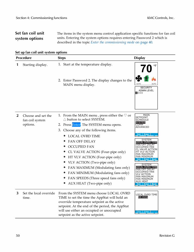
1 Starting display. 1. Start at the temperature display.
2. Enter Password 2. The display changes to theMAIN menu display.
F°
70
AUTO AUTO
SECURITY
ADMIN LEVEL
0 0 0 0
2 Choose and set thefan coil systemoptions.
1. From the MAIN menu , press either the orbutton to select SYSTEM.
2. Press Enter. The SYSTEM menu opens.3. Choose any of the following items.
LOCAL OVRD TIMEFAN OFF DELAYOCCUPIED FANCL VALVE ACTION (Four-pipe only)HT VLV ACTION (Four-pipe only)VLV ACTION (Two-pipe only)FAN MAXIMUM (Modulating fans only)FAN MINIMUM (Modulating fans only)FAN SPEEDS (Three speed fans only)AUX HEAT (Two-pipe only)
MAIN
SETPOINT
SCHEDULE
SYSTEM
COMM
ADVANCED
BackEnterExit
SYSTEM
LOCAL OVRD TIME
FAN OFF DELAY
OCCUPIED FAN
CL VALVE ACTION
HT VLV ACTION
FAN MAXIMUM
FAN MINIMUM
BackEnterExit
SYSTEM
LOCAL OVRD TIME
FAN OFF DELAY
OCCUPIED FAN
VLV ACTION
FAN MAXIMUM
FAN MINIMUM
AUX HEAT
BackEnterExit
3 Set the local overridetime.
From the SYSTEM menu choose LOCAL OVRDTIME to set the time the AppStat will hold anoverride temperature setpoint as the activesetpoint. At the end of the period, the AppStatwill use either an occupied or unoccupiedsetpoint as the active setpoint.
BackEnterCncl
LOCAL OVRD TIME
2 60 mins
Set up fan coil unit system options
Section 4: Commissioning functions KMCControls, Inc.
50 Revision G

Procedure Steps Display
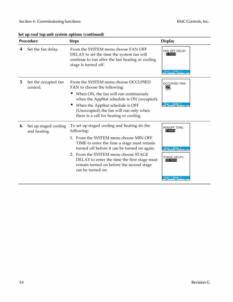
4 Set the fan delay. From the SYSTEM menu choose FAN DELAYOFF to set the time the system fan will continueto run after the last heating or cooling stage isturned off.
BackEnterCncl
FAN OFF DELAY
2 2 mins
5 Set the occupied fancontrol.
From the SYSTEM menu choose OCCUPIEDFAN to choose the following:When ON, the fan will run continuouslywhen the schedule is occupied (On).When the schedule is unoccupied (Off) thefan will run only when there is a call forheating or cooling.
BackEnterCncl
OCCUPIED FAN:
ON
OFF
6 Set the valve action. Select one of the valve actions from theSYSTEM menu. Not all choices apply to everyapplication.
CL VALVE ACTION—(Four-pipe only)HT VLV ACTION—(Four-pipe only)VLV ACTION—(Two-pipe only)
Valve action selections are the same for all threetypes of valves.
NORMAL OPEN—The valve changes fromfully open to fully closed as the AppStatvaries the valve output from 0 to 10 volts.NORMAL CLOSED—The valve changesfrom fully closed to fully open as theAppStat varies the valve output from 0 to 10volts.
CL VLV ACTION:
NORMAL OPEN
NORMAL CLOSED
DelEnterCncl
HT VLV ACTION:
NORMAL OPEN
NORMAL CLOSED
DelEnterCncl
VLV ACTION:
NORMAL OPEN
NORMAL CLOSED
DelEnterCncl
Set up fan coil unit system options (continued)
Installation, Operation, and Application Guide for AppStat Section 4: Commissioning functions
Revision G 51
Procedure Steps Display
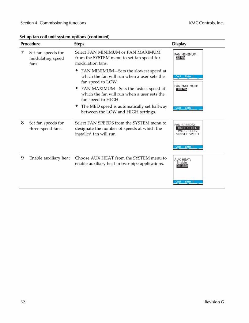
7 Set fan speeds formodulating speedfans.
Select FAN MINIMUM or FAN MAXIMUMfrom the SYSTEM menu to set fan speed formodulation fans.
FAN MINIMUM—Sets the slowest speed atwhich the fan will run when a user sets thefan speed to LOW.FAN MAXIMUM—Sets the fastest speed atwhich the fan will run when a user sets thefan speed to HIGH.The MED speed is automatically set halfwaybetween the LOW and HIGH settings.
BackEnterCncl
FAN MINIMUM:
35 %utoz
BackEnterCncl
FAN MAXIMUM:
100 %utoz
8 Set fan speeds forthree-speed fans.
Select FAN SPEEDS from the SYSTEM menu todesignate the number of speeds at which theinstalled fan will run.
BackEnterCncl
FAN SPEEDS:
THREE SPEEDS
TWO SPEEDS
SINGLE SPEED
9 Enable auxiliary heat Choose AUX HEAT from the SYSTEM menu toenable auxiliary heat in two-pipe applications.
AUX HEAT:
Enable
Disable
DelEnterCncl
Set up fan coil unit system options (continued)
Section 4: Commissioning functions KMCControls, Inc.
52 Revision G
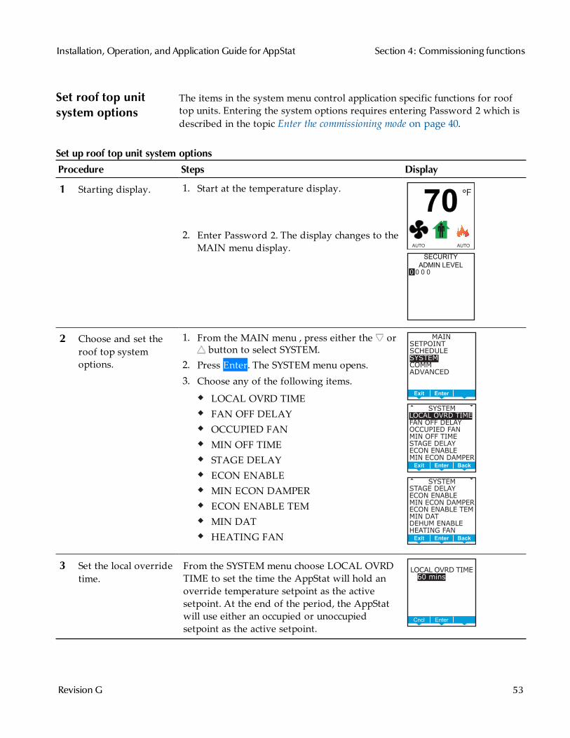
Set roof top unitsystem options
The items in the system menu control application specific functions for rooftop units. Entering the system options requires entering Password 2 which isdescribed in the topic Enter the commissioning mode on page 40.
Procedure Steps Display
1 Starting display. 1. Start at the temperature display.
2. Enter Password 2. The display changes to theMAIN menu display.
F°
70
AUTO AUTO
SECURITY
ADMIN LEVEL
0 0 0 0
2 Choose and set theroof top systemoptions.
1. From the MAIN menu , press either the orbutton to select SYSTEM.
2. Press Enter. The SYSTEM menu opens.3. Choose any of the following items.
LOCAL OVRD TIMEFAN OFF DELAYOCCUPIED FANMIN OFF TIMESTAGE DELAYECON ENABLEMIN ECON DAMPERECON ENABLE TEMMIN DATHEATING FAN
MAIN
SETPOINT
SCHEDULE
SYSTEM
COMM
ADVANCED
BackEnterExit
BackEnterExit
SYSTEM
LOCAL OVRD TIME
FAN OFF DELAY
OCCUPIED FAN
MIN OFF TIME
STAGE DELAY
ECON ENABLE
MIN ECON DAMPER
SYSTEM
STAGE DELAY
ECON ENABLE
MIN ECON DAMPER
ECON ENABLE TEM
MIN DAT
DEHUM ENABLE
HEATING FAN
BackEnterExit
3 Set the local overridetime.
From the SYSTEM menu choose LOCAL OVRDTIME to set the time the AppStat will hold anoverride temperature setpoint as the activesetpoint. At the end of the period, the AppStatwill use either an occupied or unoccupiedsetpoint as the active setpoint.
BackEnterCncl
LOCAL OVRD TIME
2 60 mins
Set up roof top unit system options
Installation, Operation, and Application Guide for AppStat Section 4: Commissioning functions
Revision G 53
Procedure Steps Display
4 Set the fan delay. From the SYSTEM menu choose FAN OFFDELAY to set the time the system fan willcontinue to run after the last heating or coolingstage is turned off.
BackEnterCncl
FAN OFF DELAY
2 2 mins
5 Set the occupied fancontrol.
From the SYSTEM menu choose OCCUPIEDFAN to choose the following:When ON, the fan will run continuouslywhen the AppStat schedule is ON (occupied).When the AppStat schedule is OFF(Unoccupied) the fan will run only whenthere is a call for heating or cooling.
BackEnterCncl
OCCUPIED FAN:
ON
OFF
6 Set up staged coolingand heating.
To set up staged cooling and heating do thefollowing:
1. From the SYSTEM menu choose MIN OFFTIME to enter the time a stage must remainturned off before it can be turned on again.
2. From the SYSTEM menu choose STAGEDELAY to enter the time the first stage mustremain turned on before the second stagecan be turned on.
BackEnterCncl
MINOFF TIME:
5 mins
BackEnterCncl
STAGE DELAY:
10 mins
Set up roof top unit system options (continued)
Section 4: Commissioning functions KMCControls, Inc.
54 Revision G
Procedure Steps Display
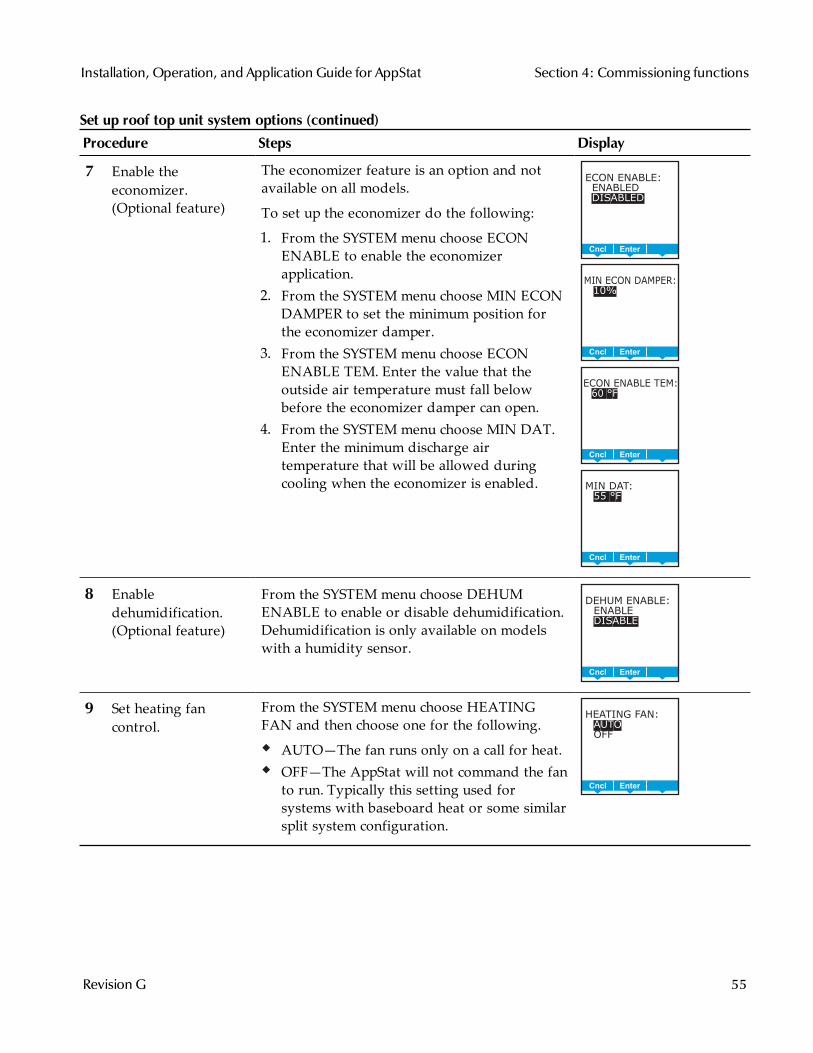
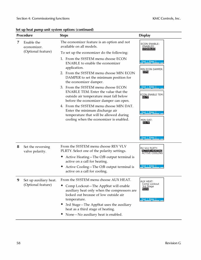
7 Enable theeconomizer.(Optional feature)
The economizer feature is an option and notavailable on all models.
To set up the economizer do the following:
1. From the SYSTEM menu choose ECONENABLE to enable the economizerapplication.
2. From the SYSTEM menu choose MIN ECONDAMPER to set the minimum position forthe economizer damper.
3. From the SYSTEM menu choose ECONENABLE TEM. Enter the value that theoutside air temperature must fall belowbefore the economizer damper can open.
4. From the SYSTEM menu choose MIN DAT.Enter the minimum discharge airtemperature that will be allowed duringcooling when the economizer is enabled.
BackEnterCncl
ECON ENABLE:
ENABLED
DISABLED
BackEnterCncl
MIN ECON DAMPER:
10%
BackEnterCncl
ECON ENABLE TEM:
60 °F
BackEnterCncl
MIN DAT:
55 °F
8 Enabledehumidification.(Optional feature)
From the SYSTEM menu choose DEHUMENABLE to enable or disable dehumidification.Dehumidification is only available on modelswith a humidity sensor.
BackEnterCncl
DEHUM ENABLE:
ENABLE
DISABLE
9 Set heating fancontrol.
From the SYSTEM menu choose HEATINGFAN and then choose one for the following.
AUTO—The fan runs only on a call for heat.OFF—The AppStat will not command the fanto run. Typically this setting used forsystems with baseboard heat or some similarsplit system configuration.
BackEnterCncl
HEATING FAN:
AUTO
OFF
Set up roof top unit system options (continued)
Installation, Operation, and Application Guide for AppStat Section 4: Commissioning functions
Revision G 55
Set heat pump unitsystem options
The items in the system menu control application specific functions for heatpump units. Entering the system options requires entering Password 2 whichis described in the topic Enter the commissioning mode on page 40.
Procedure Steps Display
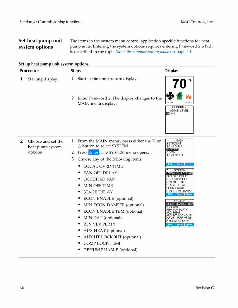
1 Starting display. 1. Start at the temperature display.
2. Enter Password 2. The display changes to theMAIN menu display.
F°
70
AUTO AUTO
SECURITY
ADMIN LEVEL
0 0 0 0
2 Choose and set theheat pump systemoptions.
1. From the MAIN menu , press either the orbutton to select SYSTEM.
2. Press Enter. The SYSTEM menu opens.3. Choose any of the following items.
LOCAL OVRD TIMEFAN OFF DELAYOCCUPIED FANMIN OFF TIMESTAGE DELAYECON ENABLE (optional)MIN ECON DAMPER (optional)ECON ENABLE TEM (optional)MIN DAT (optional)REV VLV PLRTYAUX HEAT (optional)AUX HT LOCKOUT (optional)COMP LOCK TEMPDEHUM ENABLE (optional)
MAIN
SETPOINT
SCHEDULE
SYSTEM
COMM
ADVANCED
BackEnterExit
BackEnterExit
SYSTEM
LOCAL OVRD TIME
FAN OFF DELAY
OCCUPIED FAN
MIN OFF TIME
STAGE DELAY
ECON ENABLE
MIN ECON DAMPER
SYSTEM
ECON ENABLE TEM
MIN DAT
REV VLV PLRTY
AUX HEAT
AUX HT LOCKOUT
COMP LOCK TEMP
DEHUM ENABLE
BackEnterExit
Set up heat pump unit system options
Section 4: Commissioning functions KMCControls, Inc.
56 Revision G
Procedure Steps Display
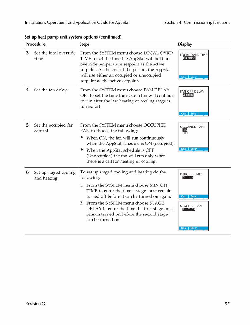
3 Set the local overridetime.
From the SYSTEM menu choose LOCAL OVRDTIME to set the time the AppStat will hold anoverride temperature setpoint as the activesetpoint. At the end of the period, the AppStatwill use either an occupied or unoccupiedsetpoint as the active setpoint.
BackEnterCncl
LOCAL OVRD TIME
2 60 mins
4 Set the fan delay. From the SYSTEM menu choose FAN DELAYOFF to set the time the system fan will continueto run after the last heating or cooling stage isturned off.
BackEnterCncl
FAN OFF DELAY
2 2 mins
5 Set the occupied fancontrol.
From the SYSTEM menu choose OCCUPIEDFAN to choose the following:
When ON, the fan will run continuouslywhen the AppStat schedule is ON (occupied).When the AppStat schedule is OFF(Unoccupied) the fan will run only whenthere is a call for heating or cooling.
BackEnterCncl
OCCUPIED FAN:
ON
OFF
6 Set up staged coolingand heating.
To set up staged cooling and heating do thefollowing:
1. From the SYSTEM menu choose MIN OFFTIME to enter the time a stage must remainturned off before it can be turned on again.
2. From the SYSTEM menu choose STAGEDELAY to enter the time the first stage mustremain turned on before the second stagecan be turned on.
BackEnterCncl
MINOFF TIME:
5 mins
BackEnterCncl
STAGE DELAY:
10 mins
Set up heat pump unit system options (continued)
Installation, Operation, and Application Guide for AppStat Section 4: Commissioning functions
Revision G 57
Procedure Steps Display
7 Enable theeconomizer.(Optional feature)
The economizer feature is an option and notavailable on all models.
To set up the economizer do the following:
1. From the SYSTEM menu choose ECONENABLE to enable the economizerapplication.
2. From the SYSTEM menu choose MIN ECONDAMPER to set the minimum position forthe economizer damper.
3. From the SYSTEM menu choose ECONENABLE TEM. Enter the value that theoutside air temperature must fall belowbefore the economizer damper can open.
4. From the SYSTEM menu choose MIN DAT.Enter the minimum discharge airtemperature that will be allowed duringcooling when the economizer is enabled.
BackEnterCncl
ECON ENABLE:
ENABLED
DISABLED
BackEnterCncl
MIN ECON DAMPER:
10%
BackEnterCncl
ECON ENABLE TEM:
60 °F
BackEnterCncl
MIN DAT:
55 °F
8 Set the reversingvalve polarity.
From the SYSTEM menu choose REV VLVPLRTY. Select one of the polarity settings.
Active Heating—The O/B output terminal isactive on a call for heating.Active Cooling—The O/B output terminal isactive on a call for cooling.
DelEnterCncl
RV VLV PLRTY:
ACTIVE HEATING
ACTIVE COOLING
9 Set up auxiliary heat.(Optional feature)
From the SYSTEM menu choose AUX HEAT.
Comp Lockout—The AppStat will enableauxiliary heat only when the compressors arelocked out because of low outside airtemperature.3rd Stage—The AppStat uses the auxiliaryheat as a third stage of heating.None—No auxiliary heat is enabled.
DelEnterCncl
AUX HEAT:Comp Lockout3rd StageNone
Set up heat pump unit system options (continued)
Section 4: Commissioning functions KMCControls, Inc.
58 Revision G
Procedure Steps Display
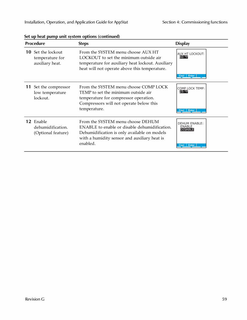
10 Set the lockouttemperature forauxiliary heat.
From the SYSTEM menu choose AUX HTLOCKOUT to set the minimum outside airtemperature for auxiliary heat lockout. Auxiliaryheat will not operate above this temperature.
DelEnterCncl
AUX HT LOCKOUT:
60 °F
11 Set the compressorlow temperaturelockout.
From the SYSTEM menu choose COMP LOCKTEMP to set the minimum outside airtemperature for compressor operation.Compressors will not operate below thistemperature.
DelEnterCncl
COMP LOCK TEMP:
25 °F
12 Enabledehumidification.(Optional feature)
From the SYSTEM menu choose DEHUMENABLE to enable or disable dehumidification.Dehumidification is only available on modelswith a humidity sensor and auxiliary heat isenabled.
BackEnterCncl
DEHUM ENABLE:
ENABLE
DISABLE
Set up heat pump unit system options (continued)
Installation, Operation, and Application Guide for AppStat Section 4: Commissioning functions
Revision G 59
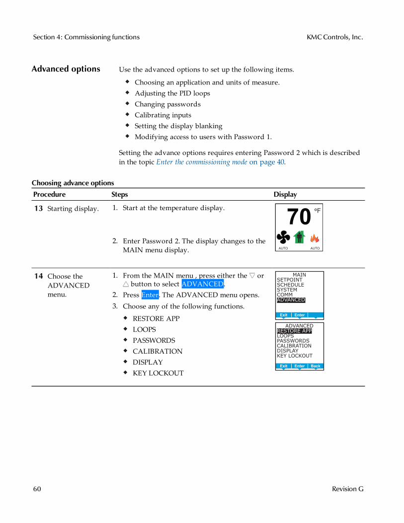
Advanced options Use the advanced options to set up the following items.
Choosing an application and units of measure.Adjusting the PID loopsChanging passwordsCalibrating inputsSetting the display blankingModifying access to users with Password 1.
Setting the advance options requires entering Password 2 which is describedin the topic Enter the commissioning mode on page 40.
Procedure Steps Display
13 Starting display. 1. Start at the temperature display.
2. Enter Password 2. The display changes to theMAIN menu display.
F°
70
AUTO AUTO
14 Choose theADVANCEDmenu.
1. From the MAIN menu , press either the orbutton to select ADVANCED.
2. Press Enter. The ADVANCED menu opens.3. Choose any of the following functions.
RESTORE APPLOOPSPASSWORDSCALIBRATIONDISPLAYKEY LOCKOUT
MAIN
SETPOINT
SCHEDULE
SYSTEM
COMM
ADVANCED
BackEnterExit
ADVANCED
RESTORE APP
LOOPS
PASSWORDS
CALIBRATION
DISPLAY
KEY LOCKOUT
BackEnterExit
Choosing advance options
Section 4: Commissioning functions KMCControls, Inc.
60 Revision G
Procedure Steps Display
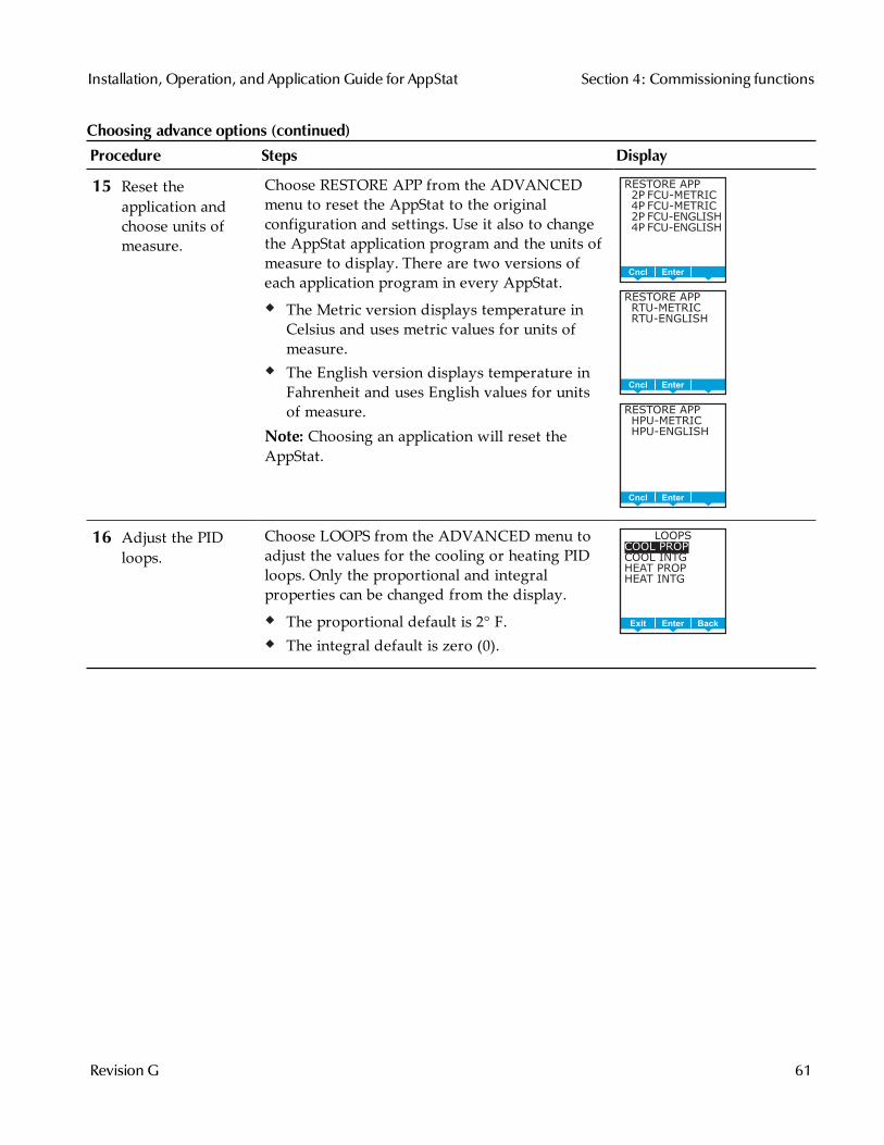
15 Reset theapplication andchoose units ofmeasure.
Choose RESTORE APP from the ADVANCEDmenu to reset the AppStat to the originalconfiguration and settings. Use it also to changethe AppStat application program and the units ofmeasure to display. There are two versions ofeach application program in every AppStat.
The Metric version displays temperature inCelsius and uses metric values for units ofmeasure.The English version displays temperature inFahrenheit and uses English values for unitsof measure.
Note: Choosing an application will reset theAppStat.
RESTORE APP
2P FCU-METRIC
4P FCU-METRIC
2P FCU-ENGLISH
4P FCU-ENGLISH
BackEnterCncl
RESTORE APP
RTU-METRIC
RTU-ENGLISH
BackEnterCncl
RESTORE APP
HPU-METRIC
HPU-ENGLISH
BackEnterCncl
16 Adjust the PIDloops.
Choose LOOPS from the ADVANCED menu toadjust the values for the cooling or heating PIDloops. Only the proportional and integralproperties can be changed from the display.
The proportional default is 2° F.The integral default is zero (0).
LOOPS
COOL PROP
COOL INTG
HEAT PROP
HEAT INTG
BackEnterExit
Choosing advance options (continued)
Installation, Operation, and Application Guide for AppStat Section 4: Commissioning functions
Revision G 61

Procedure Steps Display
17 Enter or changepasswords.
Choose PASSWORDS from the ADVANCEDmenu to set either Password 1 or Password 2.
Password 1 is for a facility user and limitschanges to active setpoints, fan operation,occupancy, and heating and cooling modes.Password 2 is for a controls technician to setup and commission the AppStat.
Note: Entering four zeros (0000) removes thepassword. The AppStat is supplied withoutpasswords.
1. From the PASSWORD1 or PASSWORD2 menupress either the or buttons to change thefirst digit of the password.
2. Press the Enter button to select the next digit.Repeat for all four digits.
3. When the Enter button is pressed for the lastdigit, the new password is saved and thedisplay advances.
PASSWORDS
PASSWORD1
PASSWORD2
BackEnterExit
PASSWORD1:
0 0 0 0
DelEnterCncl
18 Calibrate theinputs.
Choose CALIBRATION from the ADVANCEDmenu to calibrated an input. The AppStatincludes two calibration entries; one for theinternal temperature sensor and one for theoptional remote temperature sensor connected tothe RS terminal.
Enter a calibration factor to adjust either inputfor sensor inaccuracies.
For a low input reading enter a positivecorrection value.For a high input reading enter a negativecorrection value.
CALIBRATION
CAL INTERNAL
CAL EXTERNAL
BackEnterExit
CAL INTERNAL:
0.0
BackEnterCncl
Choosing advance options (continued)
Section 4: Commissioning functions KMCControls, Inc.
62 Revision G
Procedure Steps Display
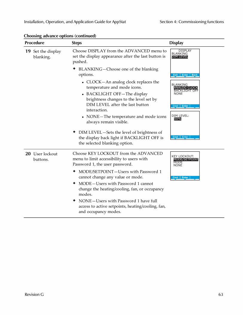
19 Set the displayblanking.
Choose DISPLAY from the ADVANCED menu toset the display appearance after the last button ispushed.
BLANKING—Choose one of the blankingoptions.
l CLOCK—An analog clock replaces thetemperature and mode icons.
l BACKLIGHT OFF—The displaybrightness changes to the level set byDIM LEVEL after the last buttoninteraction.
l NONE—The temperature and mode iconsalways remain visible.
DIM LEVEL—Sets the level of brightness ofthe display back light if BACKLIGHT OFF isthe selected blanking option.
DISPLAY
BLANKING
DIM LEVEL
BackEnterExit
BLANKING
ANALOG CLOCK
BACKLIGHT OFF
NONE
DelEnterCncl
DIM LEVEL:
50%
DelEnterCncl
20 User lockoutbuttons.
Choose KEY LOCKOUT from the ADVANCEDmenu to limit accessibility to users withPassword 1, the user password.
MODE/SETPOINT—Users with Password 1cannot change any value or mode.MODE—Users with Password 1 cannotchange the heating/cooling, fan, or occupancymodes.NONE—Users with Password 1 have fullaccess to active setpoints, heating/cooling, fan,and occupancy modes.
KEY LOCKOUT:MODE/SETPOINTMODENONE
DelEnterCncl
Choosing advance options (continued)
Installation, Operation, and Application Guide for AppStat Section 4: Commissioning functions
Revision G 63
Section 4: Commissioning functions KMCControls, Inc.
64 Revision G
Sec t ion 5: Sequences o f ope rat ion
Topics in this section cover the sequences of operation for the AppStat.These are advanced topics for control's technicians and engineers.
This section covers the following sequences of operation.
Room temperature setpoints on page 66Occupancy, motion sensing, and standby on page 67Automatic cooling and heating changeover on page 68Scheduling occupancy on page 68Dehumidification sequence on page 68Fan status on page 68Display blanking and backlight on page 69Temperature sensing inputs on page 69PID control loops on page 70Valve operation for fan coil units on page 70Electric heat for fan coil units on page 72Fan operation for fan coil units on page 72Modulating cooling and heating for Roof Top Units on page 73Staged heating and cooling for for roof top and heat pump units on page 74Fan control for roof top and heat pump units on page 74Economizer cooling for roof top and heat pump units on page 75Heat pump unit specific functions on page 75
Installation, Operation, and Application Guide for AppStat
Revision G 65
Room temperaturesetpoints
There are four temperature setpoints each for heating and cooling for a totalof eight setpoints.
Active coolingOccupied coolingUnoccupied coolingStandby coolingActive heatingOccupied heatingUnoccupied heatingStandby heating
Types of setpointsThe AppStat uses any of the following setpoints based on a user enteredsetpoint or the state of occupancy and standby which is described in the topicOccupancy, motion sensing, and standby on page 67.
Active setpoint—The active setpoint is the current setpoint. The activesetpoint is determined by the following.
If the space is occupied, the controller uses the occupied setpoint as theactive setpoint.If the space is unoccupied the controller uses the unoccupied setpoint asthe active setpoint.If controller occupancy is in standby, the controller calculates thestandby setpoint.A user with Password 1 can enter an active setpoint from the display.This change is for a limited time or until the next time the space statuschanges from either unoccupied or standby to occupied.
Occupied setpoint—A temperature setpoint entered by the controlstechnician during controller setup and system commissioning. This is thesetpoint used when the system is occupied which is usually controlled by theschedule in the controller.
Unoccupied setpoint—A temperature setpoint entered by the controlstechnician during controller setup and system commissioning. This is thesetpoint used when the system is unoccupied which is usually controlled bythe schedule in the controller.
Standby setpoint—The standby setpoint is used when the controller is in thestandby state. It is a value calculated from the occupied setpoint and the valueof Standby Offset. The standby offset value is entered by the controlstechnician during controller setup and system commissioning. See the topicOccupancy, motion sensing, and standby on page 67.
Section 5: Sequences of operation KMCControls, Inc.
66 Revision G
Setpoint limitsThe programming in the AppStat will limit the setpoint entry so that noheating setpoint is set higher than its corresponding cooling setpoint.
If a user is adjusting a setpoint and it falls within the range set by the value ofMinimum Setpoint Differential, the corresponding setpoint will be changed tomaintain the differential. For example, the Minimum Setpoint Differential is4° F and the Occupied Heating setpoint is 70° F. If the user lowers theOccupied Cooling setpoint to 71° F, the controller recalculates the OccupiedHeating setpoint and changes it to 67° F.
Occupancy, motionsensing, andstandby
The AppStat is designed to operate as a stand-alone controller and candetermine occupancy based on its internal occupancy schedule and, on modelswith motion sensors, motion in the space. The AppStat can be in any one ofthe following occupancy states.
OccupiedUnoccupiedStandby
The controller chooses which setpoint to use based on the occupancy andstandby states. See the topic Room temperature setpoints on page 66 for thesequence on determining setpoints.
The occupancy and standby states can also be commanded by anotherBACnet device or an operator workstation connected to the buildingautomation network. See the topic BACnet objects on page 114 for details onBACnet value object configuration.
Occupied—For controllers without a motion sensor, the AppStat starts in theoccupied state. If the internal schedule is enabled, the state of the schedule isset to either occupied or unoccupied as the initial state. See the topic Schedulingoccupancy on page 68.
Unoccupied—The controller changes to the Unoccupied state only if theinternal occupancy schedule is enabled and if the schedule is inactive.
Standby—In units with a motion sensor, the controller starts in standby andchanges to occupied only after detecting motion in the space. The controllerwill change from occupied to standby after a lack of motion for the periodspecified by the variable Standby Time.
Installation, Operation, and Application Guide for AppStat Section 5: Sequences of operation
Revision G 67
Automatic coolingand heatingchangeover
The AppStat can be set to automatically change between the heating andcooling modes.
If the space temperature rises above the active cooling setpoint, themode is set to cooling.If the space temperature falls below the heating setpoint, the mode is setto heating.
For fan coil models, the changeover is immediate. For other models, thechangeover does not take place until the time set by Fan Off Delay expires.
Schedulingoccupancy
The schedule in the controller is a standard BACnet schedule object. It can bechanged from the display by a technician with Password 2 or a BACnetoperator workstation.
The internal occupancy schedule changes the AppStat between the occupied(Active) and unoccupied (inactive) states. If the AppStat includes a motionsensor, the motion sensor may change the AppStat between occupied andstandby based on motion detected in the space.
See also the topic Occupancy, motion sensing, and standby on page 67.
Dehumidificationsequence
Dehumidification control is available only on models with internal humiditysensors. Dehumidification is not available for fan coil units configured fortwo-pipe operation.
The AppStat can run the dehumidification sequence only if the heating andcooling modes are set to automatic. The dehumidification sequence can thenstart if the space humidity rises above the value of Dehumidification Setpoint.Dehumidification stops when the space humidity drops to a value below theDehumidification Setpoint minus the value of Dehumidification Differential.The dehumidification setpoint and differential are both adjustable from theuser interface.
When Dehumidification is active, cooling output is activated to 100%. Heatingthen reheats the discharge air to maintain the space temperature to the valueof Active Cooling setpoint.
The controller continuously runs the fan during dehumidification regardlessof other fan settings.
Fan status Fan status is a second function of the Discharge Air Temperature (DAT)input. The function requires a normally closed fan status switch connectedacross the DAT input terminals. When the fan is started at any speed, theAppStat program waits 10 seconds for the Fan Status switch (FST) to open. Ifthe status switch does not open within 10 seconds after the fan is commandedto start, all heating and cooling is commanded to stop heating and cooling at
Section 5: Sequences of operation KMCControls, Inc.
68 Revision G
BACnet priority 5. The fan output remains enabled until the fan status switchopens. The state of fan status is stored in a binary variable. See the topic Valueobjects on page 117 for variable object details.
When the fan is functioning normally and the fan status switch is open theDAT input is normal temperature sensing input. When the fan status switch isclosed, the value for the DAT input is greater than 260. See the topicTemperature sensing inputs on page 69.
Display blankingand backlight
The AppStat display and backlight can be set to take any of the followingactions one minute after the last button is pushed.
Display an analog clock instead of the temperature display.Dim the display to a preset level.Remain unchanged.
When the display is dimmed or the clock is visible, the display returns tonormal when any button is pushed. See the topic Advanced options on page 60for the procedure to change the display.
Temperaturesensing inputs
The AppStat includes inputs for sensing space, discharge air, fan coil unitsupply water, and outside air temperature.
Space temperature sensingAll models of AppStat include an internal temperature sensor for measuringspace temperature. For remote temperature sensing, an external, 10,000 ohm,Type II thermistor sensor can be connected to terminals RS. If the AppStatdetects that a remote sensor is connected, the internal sensor is not used fordetermining space temperature. See the topics Input objects on page 114 andValue objects on page 117 for object details.
Outside air temperature sensingThe outside air temperature (OAT) input is a required input for compressorlockout and economizer applications and is an optional input for others. TheAppStat is configured for a Type III thermistor sensor to monitor outside airtemperature. The outside air temperature is also stored in an analog valueobject. See the topics Input objects on page 114 and Value objects on page 117for object details.
Water temperature sensorThe Water Temperature Sensor input (WST) is a required sensor for two-pipefan coil units and is optional for other fan coil applications. The AppStat isconfigured for a Type III thermistor sensor to monitor water temperature.The water temperature can be monitored as an analog input and is also
Installation, Operation, and Application Guide for AppStat Section 5: Sequences of operation
Revision G 69
stored in an analog value object. See the topics Input objects on page 114 andValue objects on page 117 for object details.
Discharge air temperature sensorThe Discharge Air Temperature (DAT) input is a required input foreconomizer applications and is an option for other applications. The AppStatis configured for a Type III thermistor sensor for DAT applications. Dischargeair temperature can be monitored as an analog input and is also stored in ananalog value object. See the topics Input objects on page 114 and Value objectson page 117 for object details.
The DAT input is a dual function input. It is used also as the input for the fanstatus switch. See the topic Fan status on page 68 for details.
PID control loops A PID control loop calculates an error value from the difference between themeasured room temperature and the active setpoint. The error value isexpressed as a percentage and is typically used in a BAS controller to controlthe state of an output. When the difference between the setpoint and roomtemperature is large, the error is large. As the system reduces the differencebetween the setpoint and space temperature, the error becomes smaller. In asimple example, if the output of the PID loop that is controlling a modulatingvalve is 50% the valve would be opened half way; if the output of the loop is100% the valve position is fully open.
The AppStat uses up to four PID loops.
The heating and cooling PID loops are implemented in all models.The discharge air loop controls the position of the economizer damper.For this loop the setpoint is the measured temperature of the air that isdischarged by a roof top or heat pump unit. See Economizer cooling forroof top and heat pump units on page 75.The reheat loop is used only for heating outputs unit duringdehumidification. See the sequence description Heat pump unit specificfunctions on page 75.
The PID loops in the AppStat are standard BACnet objects.
Valve operation forfan coil units
Hot and chilled water valves are used for heating and cooling in the fan coilunit versions of the AppStat. The fan coil two-pipe programming includes alsoa method to determine supply water temperature.
On/Off valvesOn a call for cooling or heating, the valve will open once the PID loopcontrolling the valve has reached 50%. The valve will close once the loop has
Section 5: Sequences of operation KMCControls, Inc.
70 Revision G
fallen to 5%. The controller programming supports both normal and reverseaction valves which can be set from the user interface.
Normal—The valve is closed when the output is inactive and open whenthe output is active.Reverse—The valve is closed when the output is active and open whenthe output is inactive.
Modulating valvesOn a call for cooling or heating, a modulating valve will modulate from 0 to100% over the first half (0 to 50%) of the PID loop output controlling thevalve. The AppStat supports both normal and reverse action valves which canbe set from the user interface.
Normal—The valve is fully closed when the output signal is 0 volts andfully open when the output is 10 volts DC.Reverse—The valve is fully closed when the output signal is 10 volts andfully open when the output is 0 volts DC.
Two-pipe water supply temperature evaluationFor two-pipe fan coil units, the AppStat uses the water supply temperaturesensor—input WST–to determine if chilled or hot water is being supplied tothe unit. The water type is determined by comparing the value of the watertemperature sensor input to the room temperature. The AppStatprogramming then determines that the water temperature is one of thefollowing.
Chilled—the water temperature is 10° F below room temperature.Hot—the water temperature is 10° F above room temperature.None—the water temperature is within 7° F of room temperature.
If the water temperature is evaluated as None, the AppStat runs the waterevaluation program every six hours. During a water evaluation, the AppStatopens the valve until a water type is determined or for five minutes,whichever is reached first. If a water evaluation is not being performed, thevalve remains closed.
The supply water type is stored in multistate variable Water Available.
Installation, Operation, and Application Guide for AppStat Section 5: Sequences of operation
Revision G 71
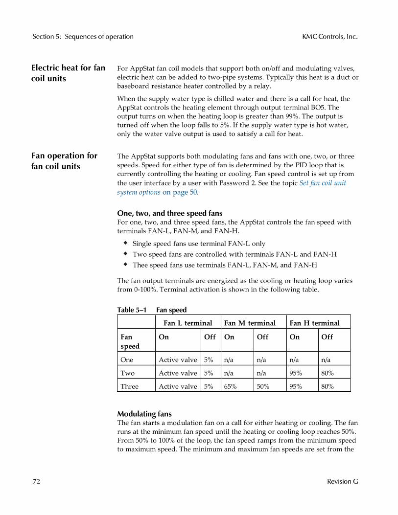
Electric heat for fancoil units
For AppStat fan coil models that support both on/off and modulating valves,electric heat can be added to two-pipe systems. Typically this heat is a duct orbaseboard resistance heater controlled by a relay.
When the supply water type is chilled water and there is a call for heat, theAppStat controls the heating element through output terminal BO5. Theoutput turns on when the heating loop is greater than 99%. The output isturned off when the loop falls to 5%. If the supply water type is hot water,only the water valve output is used to satisfy a call for heat.
Fan operation forfan coil units
The AppStat supports both modulating fans and fans with one, two, or threespeeds. Speed for either type of fan is determined by the PID loop that iscurrently controlling the heating or cooling. Fan speed control is set up fromthe user interface by a user with Password 2. See the topic Set fan coil unitsystem options on page 50.
One, two, and three speed fansFor one, two, and three speed fans, the AppStat controls the fan speed withterminals FAN-L, FAN-M, and FAN-H.
Single speed fans use terminal FAN-L onlyTwo speed fans are controlled with terminals FAN-L and FAN-HThee speed fans use terminals FAN-L, FAN-M, and FAN-H
The fan output terminals are energized as the cooling or heating loop variesfrom 0-100%. Terminal activation is shown in the following table.
Fan L terminal Fan M terminal Fan H terminal
Fanspeed
On Off On Off On Off
One Active valve 5% n/a n/a n/a n/a
Two Active valve 5% n/a n/a 95% 80%
Three Active valve 5% 65% 50% 95% 80%
Table 5–1 Fan speed
Modulating fansThe fan starts a modulation fan on a call for either heating or cooling. The fanruns at the minimum fan speed until the heating or cooling loop reaches 50%.From 50% to 100% of the loop, the fan speed ramps from the minimum speedto maximum speed. The minimum and maximum fan speeds are set from the
Section 5: Sequences of operation KMCControls, Inc.
72 Revision G
user interface during system setup. See the topic Set fan coil unit systemoptions on page 50.
Automatic fan controlA user with Password 1 can set the AppStat controlled fan to either runcontinuously or to start automatically on a call for cooling or heating.
Auto—When Auto is selected, the fan runs only when there is a call forcooling or heating. It continues to run after the call for cooling or heating forthe period set by the fan delay timer.
On—The fan will run continuously regardless of the heat/cool modes oroccupied/standby states.
Low, Medium, High—For systems with three-speed fans, the user has thechoice of low, medium or high speed as the continuous running speed for thefan.
Modulating coolingand heating for RoofTop Units
Modulating cooling and heating is used in AppStat controlled systems withmodulating valves and chilled or hot water coils. A single modulating valvecan be used with staged cooling or heating.
CoolingModulating cooling does not start until the cooling loop reaches 100%. Oncethe loop reaches 100%, the analog cooling output modulates over 10 volts DCas the cooling loop changes from 0 to 100%. When the cooling loop returns to0%, cooling stops until the loop again reaches 100%.
If the economizer is enabled, cooling will not start modulating until theeconomizer damper is fully open.
HeatingModulating heating does not start until the heating loop reaches 100%. Oncethe loop reaches 100%, the analog heating output modulates over 10 volts DCas the heating loop changes from 0 to 100%. When the heating loop returns to0%, heating stops until the loop reaches 100% again.
Valve actionThe AppStat supports both normal and reverse valve action that can be setfrom the user interface.
Normal—The valve is fully closed when the output signal is 0 volts andfully open when the output is 10 volts DC.Reverse—The valve is fully closed when the output signal is 10 volts andfully open when the output is 0 volts DC.
Installation, Operation, and Application Guide for AppStat Section 5: Sequences of operation
Revision G 73
Staged heating andcooling for for rooftop and heat pumpunits
Staged heating and cooling is used for applications other than chilled or hotwater systems. Typically the AppStat controls gas heat, electric heat, or directexpansion (DX) cooling with staged heating and cooling. Staged cooling orheating can be mixed with a modulating valve for cooling or heating.
Staged coolingAs the demand for cooling increases, the AppStat starts the first stage ofcooling when the cooling PID loop rises above 95% and the first stage ofcooling has been turned off for at least the time set by the value of MINIMUM OFF TIME. The second stage of cooling is turned on when thecooling loop rises above 99% and the first stage has been turned on for theperiod set by STAGE DELAY and the second stage has been turned off for atleast as long as the value of MINIMUM OFF TIME.
As the demand for cooling is satisfied, the second stage is turned off whenthe cooling PID loop drops below 50%. This first stage is turned off when thecooling loop drops below 5%.
Staged heatingAs the demand for heating increases, the AppStat starts the first stage ofheating when the heating PID loop rises above 95%. The second stage ofheating is turned on when the heating loop rises above 99% and the first stagehas been turned on for period set by STAGE DELAY.
As the demand for heating is satisfied, the second stage is turned off whenthe heating PID loop drops below 50%. This first stage is turned off when theheating loop drops below 5%.
Fan control for rooftop and heat pumpunits
A user with Password 1 can set the AppStat controlled fan to either runcontinuously or to start automatically on a call for cooling or heating. See thetopic Setting the operating modes on page 36 to set the fan configuration.
On—The fan will run continuously regardless of the heat/cool modes oroccupied/standby states.
Auto—When Off is selected, the fan runs only when there is a call for heatingor cooling. It continues to run for the period set by the fan delay timer afterthe call for heating or cooling.
Section 5: Sequences of operation KMCControls, Inc.
74 Revision G
Economizer coolingfor roof top andheat pump units
Some models of the AppStat include programming for an economizer. Thisprograming controls an economizer outside air damper connected to theoutput terminal (ECON).
Note: The optional economizer can be enabled only if outside air temperature anddischarge air temperature sensors are connected to the AppStat.
The optional economizer mode is enabled for cooling when the outside airtemperature (OAT) is 2° F below the value of the limit set by EconomizerEnable Temperature and disabled if the OAT is 2° F above the value ofEconomizer Enable Temperature.
Once enabled, the economizer outside air damper opens to the larger value ofeither the minimum damper position limit (Minimum Econ Damper) or theDischarge Air Temperature loop. The Discharge Air Temperature PID loopmodulates from 0% to 100% as the Discharge Air Temperature rises above theDischarge Air Temperature setpoint. The Discharge Air Temperature setpointresets between room temperature and the limit for minimum discharge airtemperature as the cooling loop varies between 0 and 50%. If the DischargeAir Temperature decreases below 55° F, the Outside Air Damper returns tothe minimum damper position.
Heat pump unitspecific functions
The fan and staging sequences for heat pump units are similar to the roof topunit fan and staging sequences. See the topics Staged heating and cooling for forroof top and heat pump units on page 74 and Fan control for roof top and heatpump units on page 74.
Reversing valve actionThe AppStat reversing valve output, terminal O/B, is energized on a call forcooling (‘O’ function). The action can be changed from the user interface tobe active on a call for heating (‘B’ function). The ‘O’ function is the default.
Auxiliary or emergency heat actionThe heat pump unit AUX/E output is for auxiliary or emergency heat.Operation can be configured for one of three modes.
Compressor lockout —The AUX/E output terminal is active only on a callfor heating when the compressors are locked out. The compressors are lockedout when the outside air temperature drops below the value of theCompressor OAT Low Limit. The lockout is cleared when the outside airtemperature rises 2° F above the value of Compressor OAT Low Limit.
Third stage—The AUX/E output functions as the output for a third stage ofheat.
Installation, Operation, and Application Guide for AppStat Section 5: Sequences of operation
Revision G 75
None—This function is a manual operation that can only be turned on fromthe user interface. When emergency heat is turned on, the AUX/E output isused to maintain the active heating setpoint and both compressor outputs arelocked-out.
Section 5: Sequences of operation KMCControls, Inc.
76 Revision G
Sec t ion 6: Appl icat ion draw ings
This section covers the drawings, materials, and instructions for specificAppStat applications.
Each AppStat model is designed for a specific application. The followingtopics are for control technicians and engineers that will plan and installAppStat controllers for the following applications.
Fan Coil Unit applications on page 78Roof Top Unit applications on page 98Heat Pump Unit applications on page 108
Installation, Operation, and Application Guide for AppStat
Revision G 77
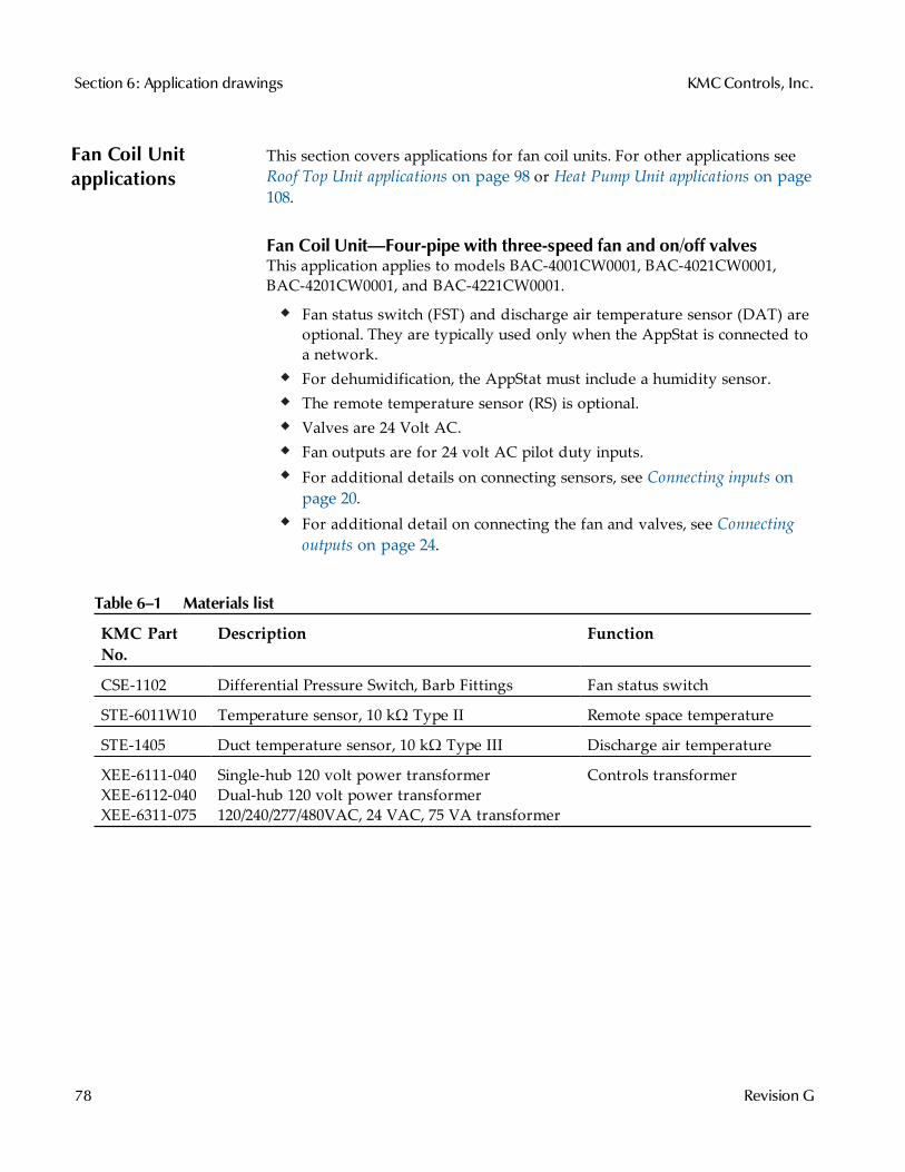
Fan Coil Unitapplications
This section covers applications for fan coil units. For other applications seeRoof Top Unit applications on page 98 or Heat Pump Unit applications on page108.
Fan Coil Unit—Four-pipe with three-speed fan and on/off valvesThis application applies to models BAC-4001CW0001, BAC-4021CW0001,BAC-4201CW0001, and BAC-4221CW0001.
Fan status switch (FST) and discharge air temperature sensor (DAT) areoptional. They are typically used only when the AppStat is connected toa network.For dehumidification, the AppStat must include a humidity sensor.The remote temperature sensor (RS) is optional.Valves are 24 Volt AC.Fan outputs are for 24 volt AC pilot duty inputs.For additional details on connecting sensors, see Connecting inputs onpage 20.For additional detail on connecting the fan and valves, see Connectingoutputs on page 24.
KMC PartNo.
Description Function
CSE-1102 Differential Pressure Switch, Barb Fittings Fan status switch
STE-6011W10 Temperature sensor, 10 kΩ Type II Remote space temperature
STE-1405 Duct temperature sensor, 10 kΩ Type III Discharge air temperature
XEE-6111-040XEE-6112-040XEE-6311-075
Single-hub 120 volt power transformerDual-hub 120 volt power transformer120/240/277/480VAC, 24 VAC, 75 VA transformer
Controls transformer
Table 6–1 Materials list
Section 6: Application drawings KMCControls, Inc.
78 Revision G
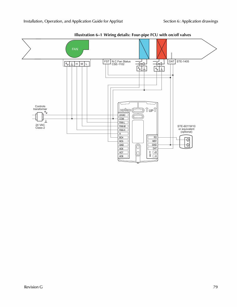
Illustration 6–1 Wiring details: Four-pipe FCU with on/off valves
H M LSTE-1405
FAN
24 VACClass-2
STE-6011W10or equivalent
(optional)
FST N.C Fan StatusCSE-1102
Controlstransformer
DAT
MS/T
P
+B
A
RS
WST
GND
DAT
COM
FAN-L
FAN-M
FAN-H
R
BO4
BO5
GND
AO6
AO8
AO7
24VAC
Installation, Operation, and Application Guide for AppStat Section 6: Application drawings
Revision G 79

Fan Coil Unit—Four-pipe with three-speed fan and modulating valvesThis application applies to models BAC-4002CW0001, BAC-4022CW0001,BAC-4202CW0001, and BAC-4222CW0001.
Fan status switch (FST) and discharge air temperature sensor (DAT) areoptional. They are typically used only when the AppStat is connected toa network.For dehumidification, the AppStat must include a humidity sensor.The remote temperature sensor (RS) is optional.Valves are 24 Volt AC with a 0–10 Volt DC control signal.Fan outputs are for 24 volt AC pilot duty inputs.For additional details on connecting sensors, see Connecting inputs onpage 20.For additional detail on connecting the fan and valves, see Connectingoutputs on page 24.
KMC PartNo.
Description Function
CSE-1102 Differential Pressure Switch, Barb Fittings Fan status switch
STE-6011W10 Temperature sensor, 10 kΩ Type II Remote space temperature
STE-1405 Duct temperature sensor, 10 kΩ Type III Discharge air temperature
XEE-6111-040XEE-6112-040XEE-6311-075
Single-hub 120 volt power transformerDual-hub 120 volt power transformer120/240/277/480VAC, 24 VAC, 75 VA transformer
Controls transformer
Table 6–2 Materials list
Section 6: Application drawings KMCControls, Inc.
80 Revision G
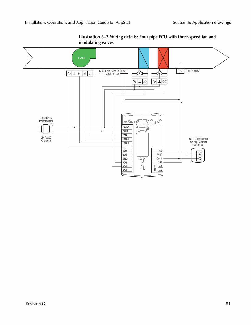
Illustration 6–2 Wiring details: Four pipe FCU with three-speed fan andmodulating valves
MS/T
P
+B
A
RS
WST
GND
DAT
COM
FAN-L
FAN-M
FAN-H
R
BO4
BO5
GND
AO6
AO8
AO7
24VAC
H M L
FAN
STE-1405
24 VACClass-2
0-10VDC
0-10VDC
FSTN.C Fan StatusCSE-1102
Controlstransformer
DAT
STE-6011W10or equivalent
(optional)
Installation, Operation, and Application Guide for AppStat Section 6: Application drawings
Revision G 81
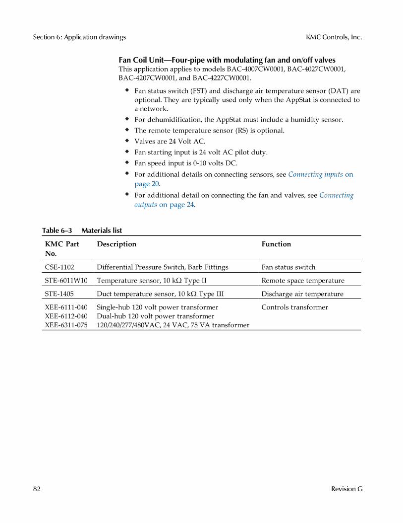
Fan Coil Unit—Four-pipe with modulating fan and on/off valvesThis application applies to models BAC-4007CW0001, BAC-4027CW0001,BAC-4207CW0001, and BAC-4227CW0001.
Fan status switch (FST) and discharge air temperature sensor (DAT) areoptional. They are typically used only when the AppStat is connected toa network.For dehumidification, the AppStat must include a humidity sensor.The remote temperature sensor (RS) is optional.Valves are 24 Volt AC.Fan starting input is 24 volt AC pilot duty.Fan speed input is 0-10 volts DC.For additional details on connecting sensors, see Connecting inputs onpage 20.For additional detail on connecting the fan and valves, see Connectingoutputs on page 24.
KMC PartNo.
Description Function
CSE-1102 Differential Pressure Switch, Barb Fittings Fan status switch
STE-6011W10 Temperature sensor, 10 kΩ Type II Remote space temperature
STE-1405 Duct temperature sensor, 10 kΩ Type III Discharge air temperature
XEE-6111-040XEE-6112-040XEE-6311-075
Single-hub 120 volt power transformerDual-hub 120 volt power transformer120/240/277/480VAC, 24 VAC, 75 VA transformer
Controls transformer
Table 6–3 Materials list
Section 6: Application drawings KMCControls, Inc.
82 Revision G
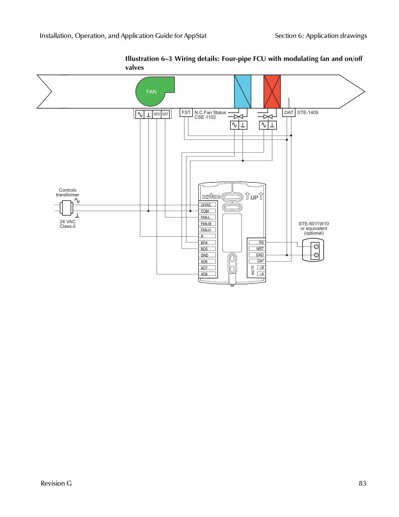
Illustration 6–3 Wiring details: Four-pipe FCU with modulating fan and on/offvalves
FAN
24 VACClass-2
FST
Controlstransformer
N.C Fan StatusCSE-1102
STE-1405
STE-6011W10or equivalent
(optional)
DATSPD SRT
MS/T
P
+B
A
RS
WST
GND
DAT
COM
FAN-L
FAN-M
FAN-H
R
BO4
BO5
GND
AO6
AO8
AO7
24VAC
Installation, Operation, and Application Guide for AppStat Section 6: Application drawings
Revision G 83
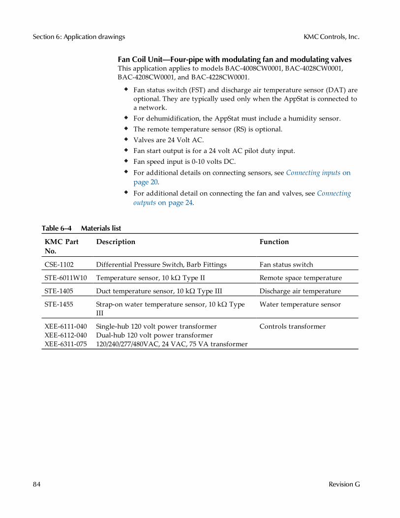
Fan Coil Unit—Four-pipe with modulating fan and modulating valvesThis application applies to models BAC-4008CW0001, BAC-4028CW0001,BAC-4208CW0001, and BAC-4228CW0001.
Fan status switch (FST) and discharge air temperature sensor (DAT) areoptional. They are typically used only when the AppStat is connected toa network.For dehumidification, the AppStat must include a humidity sensor.The remote temperature sensor (RS) is optional.Valves are 24 Volt AC.Fan start output is for a 24 volt AC pilot duty input.Fan speed input is 0-10 volts DC.For additional details on connecting sensors, see Connecting inputs onpage 20.For additional detail on connecting the fan and valves, see Connectingoutputs on page 24.
KMC PartNo.
Description Function
CSE-1102 Differential Pressure Switch, Barb Fittings Fan status switch
STE-6011W10 Temperature sensor, 10 kΩ Type II Remote space temperature
STE-1405 Duct temperature sensor, 10 kΩ Type III Discharge air temperature
STE-1455 Strap-on water temperature sensor, 10 kΩ TypeIII
Water temperature sensor
XEE-6111-040XEE-6112-040XEE-6311-075
Single-hub 120 volt power transformerDual-hub 120 volt power transformer120/240/277/480VAC, 24 VAC, 75 VA transformer
Controls transformer
Table 6–4 Materials list
Section 6: Application drawings KMCControls, Inc.
84 Revision G
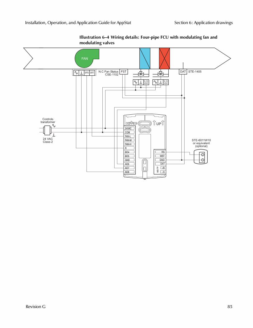
Illustration 6–4 Wiring details: Four-pipe FCU with modulating fan andmodulating valves
MS/T
P
+B
A
RS
WST
GND
DAT
COM
FAN-L
FAN-M
FAN-H
R
BO4
BO5
GND
AO6
AO8
AO7
24VAC
24 VACClass-2
0-10VDC
0-10VDC
FAN
FST
Controlstransformer
N.C Fan StatusCSE-1102
STE-1405DAT
STE-6011W10or equivalent
(optional)
SPD SRT
Installation, Operation, and Application Guide for AppStat Section 6: Application drawings
Revision G 85
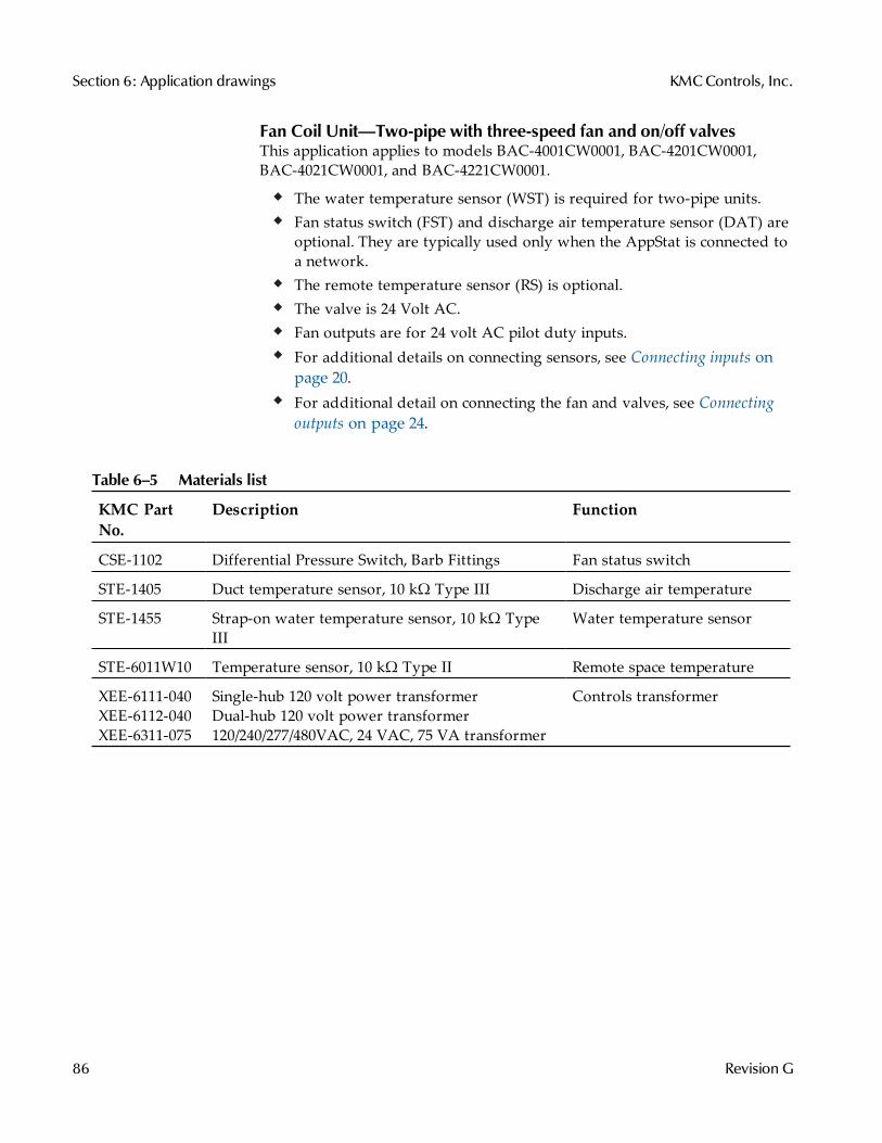
Fan Coil Unit—Two-pipe with three-speed fan and on/off valvesThis application applies to models BAC-4001CW0001, BAC-4201CW0001,BAC-4021CW0001, and BAC-4221CW0001.
The water temperature sensor (WST) is required for two-pipe units.Fan status switch (FST) and discharge air temperature sensor (DAT) areoptional. They are typically used only when the AppStat is connected toa network.The remote temperature sensor (RS) is optional.The valve is 24 Volt AC.Fan outputs are for 24 volt AC pilot duty inputs.For additional details on connecting sensors, see Connecting inputs onpage 20.For additional detail on connecting the fan and valves, see Connectingoutputs on page 24.
KMC PartNo.
Description Function
CSE-1102 Differential Pressure Switch, Barb Fittings Fan status switch
STE-1405 Duct temperature sensor, 10 kΩ Type III Discharge air temperature
STE-1455 Strap-on water temperature sensor, 10 kΩ TypeIII
Water temperature sensor
STE-6011W10 Temperature sensor, 10 kΩ Type II Remote space temperature
XEE-6111-040XEE-6112-040XEE-6311-075
Single-hub 120 volt power transformerDual-hub 120 volt power transformer120/240/277/480VAC, 24 VAC, 75 VA transformer
Controls transformer
Table 6–5 Materials list
Section 6: Application drawings KMCControls, Inc.
86 Revision G
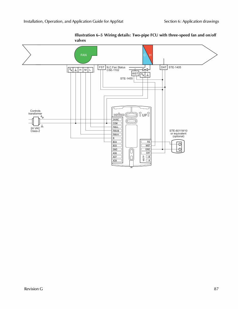
Illustration 6–5 Wiring details: Two-pipe FCU with three-speed fan and on/offvalves
H M L
FAN
24 VACClass-2
FST N.C Fan StatusCSE-1102
STE-1455
Controlstransformer
STE-1405DAT
WST
STE-6011W10or equivalent
(optional)
MS/T
P
+B
A
RS
WST
GND
DAT
COM
FAN-L
FAN-M
FAN-H
R
BO4
BO5
GND
AO6
AO8
AO7
24VAC
Installation, Operation, and Application Guide for AppStat Section 6: Application drawings
Revision G 87
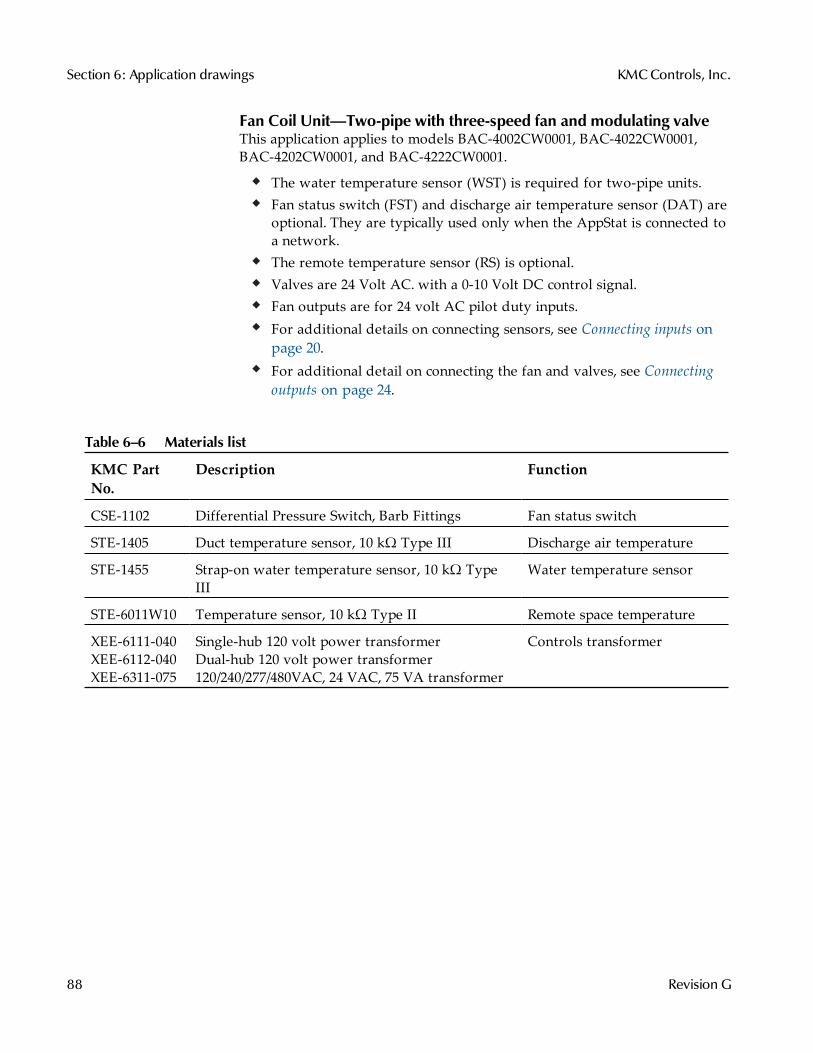
Fan Coil Unit—Two-pipe with three-speed fan and modulating valveThis application applies to models BAC-4002CW0001, BAC-4022CW0001,BAC-4202CW0001, and BAC-4222CW0001.
The water temperature sensor (WST) is required for two-pipe units.Fan status switch (FST) and discharge air temperature sensor (DAT) areoptional. They are typically used only when the AppStat is connected toa network.The remote temperature sensor (RS) is optional.Valves are 24 Volt AC. with a 0-10 Volt DC control signal.Fan outputs are for 24 volt AC pilot duty inputs.For additional details on connecting sensors, see Connecting inputs onpage 20.For additional detail on connecting the fan and valves, see Connectingoutputs on page 24.
KMC PartNo.
Description Function
CSE-1102 Differential Pressure Switch, Barb Fittings Fan status switch
STE-1405 Duct temperature sensor, 10 kΩ Type III Discharge air temperature
STE-1455 Strap-on water temperature sensor, 10 kΩ TypeIII
Water temperature sensor
STE-6011W10 Temperature sensor, 10 kΩ Type II Remote space temperature
XEE-6111-040XEE-6112-040XEE-6311-075
Single-hub 120 volt power transformerDual-hub 120 volt power transformer120/240/277/480VAC, 24 VAC, 75 VA transformer
Controls transformer
Table 6–6 Materials list
Section 6: Application drawings KMCControls, Inc.
88 Revision G
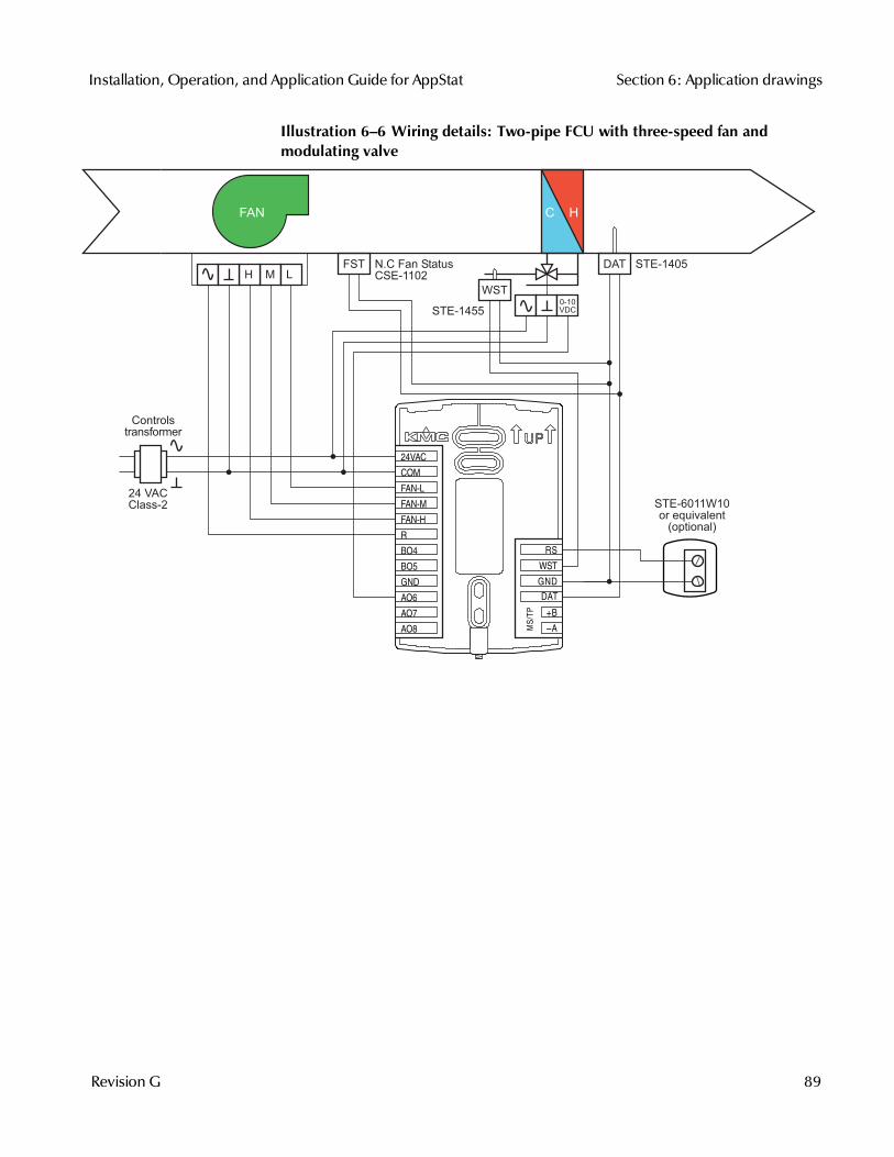
Illustration 6–6 Wiring details: Two-pipe FCU with three-speed fan andmodulating valve
H M L
FAN
24 VACClass-2
0-10VDC
FST N.C Fan StatusCSE-1102
Controlstransformer
STE-1455
STE-1405DAT
WST
STE-6011W10or equivalent
(optional)MS/T
P
+B
A
RS
WST
GND
DAT
COM
FAN-L
FAN-M
FAN-H
R
BO4
BO5
GND
AO6
AO8
AO7
24VAC
Installation, Operation, and Application Guide for AppStat Section 6: Application drawings
Revision G 89
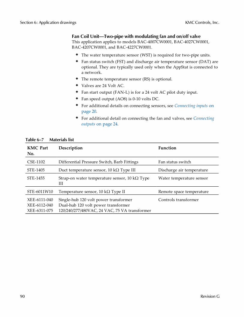
Fan Coil Unit—Two-pipe with modulating fan and on/off valveThis application applies to models BAC-4007CW0001, BAC-4027CW0001,BAC-4207CW0001, and BAC-4227CW0001.
The water temperature sensor (WST) is required for two-pipe units.Fan status switch (FST) and discharge air temperature sensor (DAT) areoptional. They are typically used only when the AppStat is connected toa network.The remote temperature sensor (RS) is optional.Valves are 24 Volt AC.Fan start output (FAN-L) is for a 24 volt AC pilot duty input.Fan speed output (AO8) is 0-10 volts DC.For additional details on connecting sensors, see Connecting inputs onpage 20.For additional detail on connecting the fan and valves, see Connectingoutputs on page 24.
KMC PartNo.
Description Function
CSE-1102 Differential Pressure Switch, Barb Fittings Fan status switch
STE-1405 Duct temperature sensor, 10 kΩ Type III Discharge air temperature
STE-1455 Strap-on water temperature sensor, 10 kΩ TypeIII
Water temperature sensor
STE-6011W10 Temperature sensor, 10 kΩ Type II Remote space temperature
XEE-6111-040XEE-6112-040XEE-6311-075
Single-hub 120 volt power transformerDual-hub 120 volt power transformer120/240/277/480VAC, 24 VAC, 75 VA transformer
Controls transformer
Table 6–7 Materials list
Section 6: Application drawings KMCControls, Inc.
90 Revision G
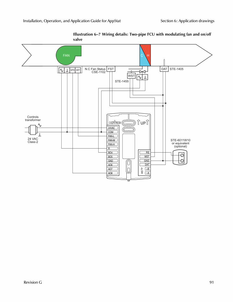
Illustration 6–7 Wiring details: Two-pipe FCU with modulating fan and on/offvalve
FAN
24 VACClass-2
FSTN.C Fan StatusCSE-1102
Controlstransformer
STE-1455
STE-1405DAT
WST
STE-6011W10or equivalent
(optional)
SPD SRT
MS/T
P
+B
A
RS
WST
GND
DAT
COM
FAN-L
FAN-M
FAN-H
R
BO4
BO5
GND
AO6
AO8
AO7
24VAC
Installation, Operation, and Application Guide for AppStat Section 6: Application drawings
Revision G 91
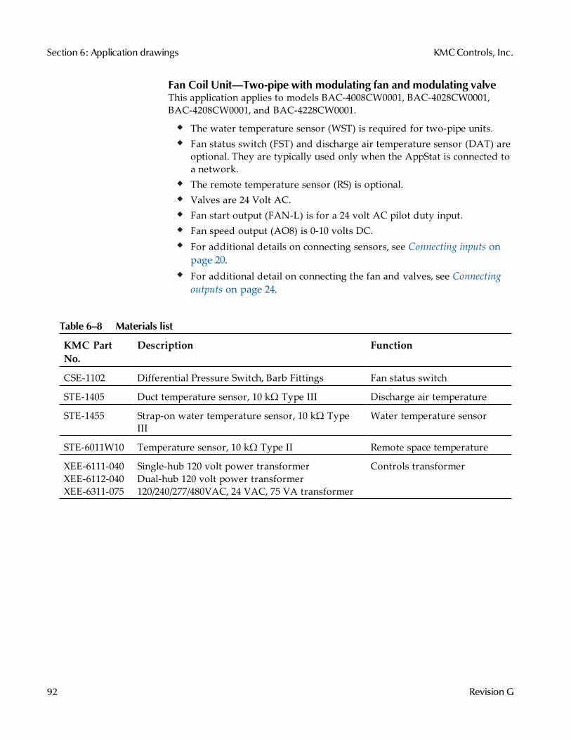
Fan Coil Unit—Two-pipe with modulating fan and modulating valveThis application applies to models BAC-4008CW0001, BAC-4028CW0001,BAC-4208CW0001, and BAC-4228CW0001.
The water temperature sensor (WST) is required for two-pipe units.Fan status switch (FST) and discharge air temperature sensor (DAT) areoptional. They are typically used only when the AppStat is connected toa network.The remote temperature sensor (RS) is optional.Valves are 24 Volt AC.Fan start output (FAN-L) is for a 24 volt AC pilot duty input.Fan speed output (AO8) is 0-10 volts DC.For additional details on connecting sensors, see Connecting inputs onpage 20.For additional detail on connecting the fan and valves, see Connectingoutputs on page 24.
KMC PartNo.
Description Function
CSE-1102 Differential Pressure Switch, Barb Fittings Fan status switch
STE-1405 Duct temperature sensor, 10 kΩ Type III Discharge air temperature
STE-1455 Strap-on water temperature sensor, 10 kΩ TypeIII
Water temperature sensor
STE-6011W10 Temperature sensor, 10 kΩ Type II Remote space temperature
XEE-6111-040XEE-6112-040XEE-6311-075
Single-hub 120 volt power transformerDual-hub 120 volt power transformer120/240/277/480VAC, 24 VAC, 75 VA transformer
Controls transformer
Table 6–8 Materials list
Section 6: Application drawings KMCControls, Inc.
92 Revision G
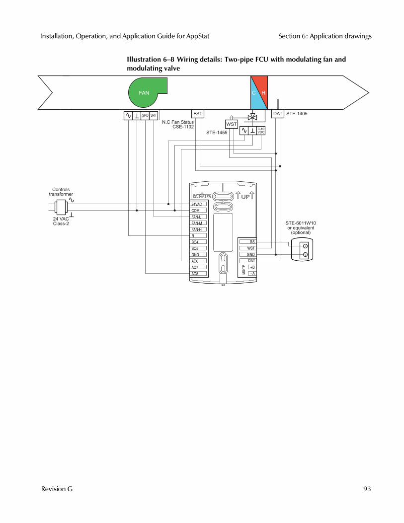
Illustration 6–8 Wiring details: Two-pipe FCU with modulating fan andmodulating valve
FAN
24 VACClass-2
0-10VDC
FST
N.C Fan StatusCSE-1102
Controlstransformer
STE-1455
STE-1405DAT
WST
STE-6011W10or equivalent
(optional)
SPD SRT
MS/T
P
+B
A
RS
WST
GND
DAT
COM
FAN-L
FAN-M
FAN-H
R
BO4
BO5
GND
AO6
AO8
AO7
24VAC
Installation, Operation, and Application Guide for AppStat Section 6: Application drawings
Revision G 93
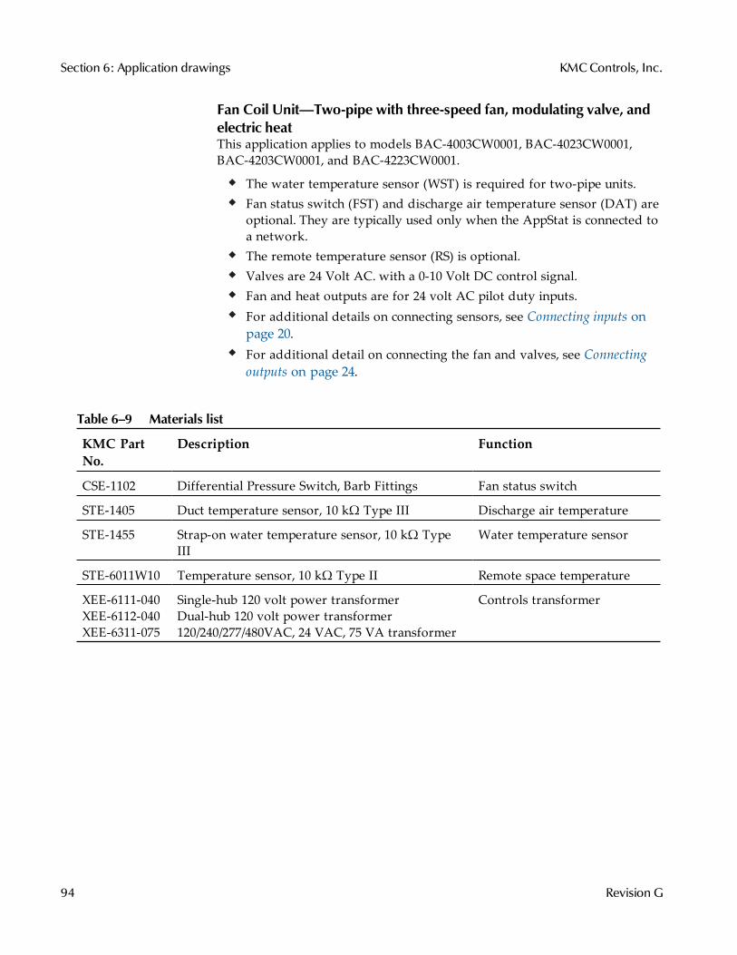
Fan Coil Unit—Two-pipe with three-speed fan, modulating valve, andelectric heatThis application applies to models BAC-4003CW0001, BAC-4023CW0001,BAC-4203CW0001, and BAC-4223CW0001.
The water temperature sensor (WST) is required for two-pipe units.Fan status switch (FST) and discharge air temperature sensor (DAT) areoptional. They are typically used only when the AppStat is connected toa network.The remote temperature sensor (RS) is optional.Valves are 24 Volt AC. with a 0-10 Volt DC control signal.Fan and heat outputs are for 24 volt AC pilot duty inputs.For additional details on connecting sensors, see Connecting inputs onpage 20.For additional detail on connecting the fan and valves, see Connectingoutputs on page 24.
KMC PartNo.
Description Function
CSE-1102 Differential Pressure Switch, Barb Fittings Fan status switch
STE-1405 Duct temperature sensor, 10 kΩ Type III Discharge air temperature
STE-1455 Strap-on water temperature sensor, 10 kΩ TypeIII
Water temperature sensor
STE-6011W10 Temperature sensor, 10 kΩ Type II Remote space temperature
XEE-6111-040XEE-6112-040XEE-6311-075
Single-hub 120 volt power transformerDual-hub 120 volt power transformer120/240/277/480VAC, 24 VAC, 75 VA transformer
Controls transformer
Table 6–9 Materials list
Section 6: Application drawings KMCControls, Inc.
94 Revision G
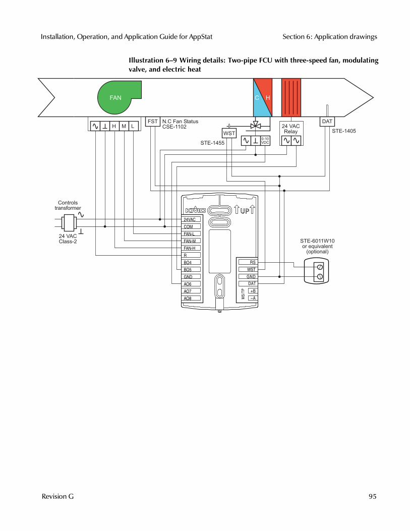
Illustration 6–9 Wiring details: Two-pipe FCU with three-speed fan, modulatingvalve, and electric heat
H M L
FAN
24 VACClass-2
0-10VDC
FST N.C Fan StatusCSE-1102
Controlstransformer
STE-1455
STE-1405
DAT
WST
STE-6011W10or equivalent
(optional)
24 VACRelay
MS/T
P
+B
A
RS
WST
GND
DAT
COM
FAN-L
FAN-M
FAN-H
R
BO4
BO5
GND
AO6
AO8
AO7
24VAC
Installation, Operation, and Application Guide for AppStat Section 6: Application drawings
Revision G 95
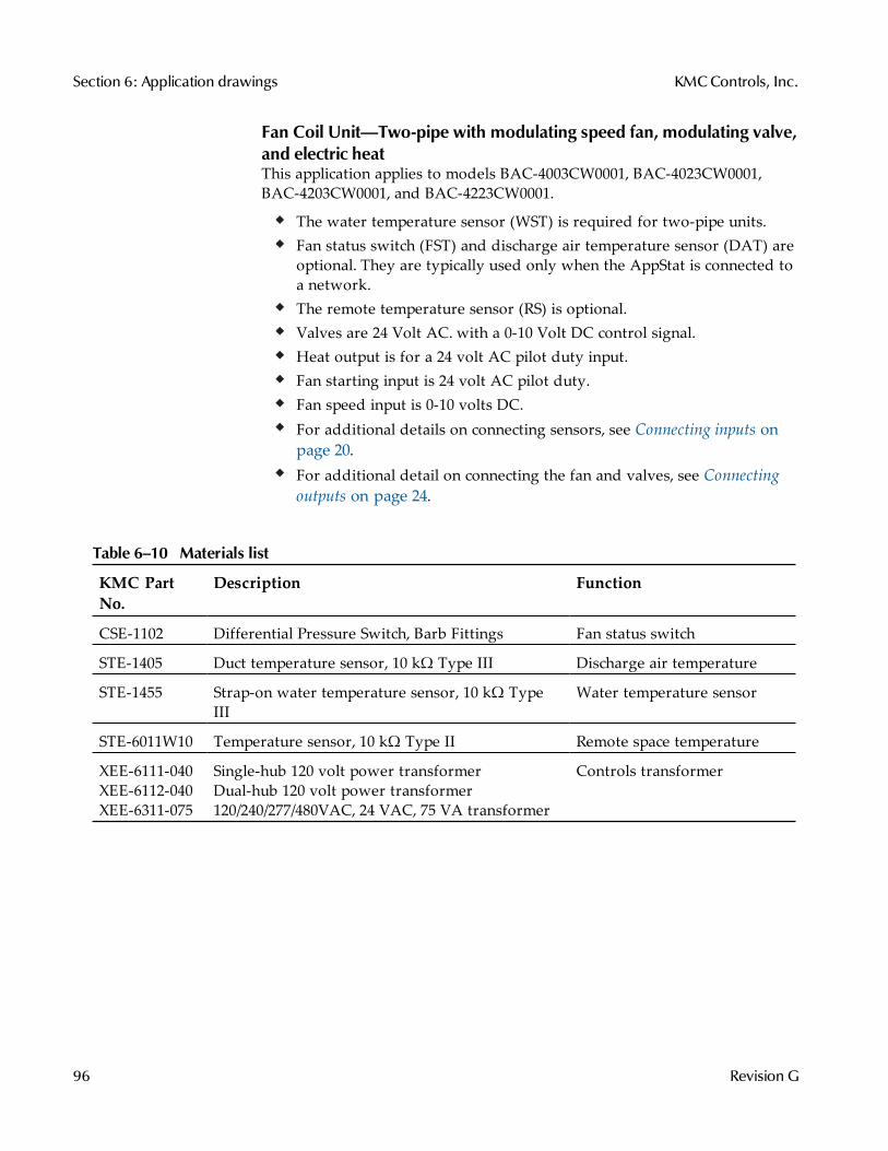
Fan Coil Unit—Two-pipe with modulating speed fan, modulating valve,and electric heatThis application applies to models BAC-4003CW0001, BAC-4023CW0001,BAC-4203CW0001, and BAC-4223CW0001.
The water temperature sensor (WST) is required for two-pipe units.Fan status switch (FST) and discharge air temperature sensor (DAT) areoptional. They are typically used only when the AppStat is connected toa network.The remote temperature sensor (RS) is optional.Valves are 24 Volt AC. with a 0-10 Volt DC control signal.Heat output is for a 24 volt AC pilot duty input.Fan starting input is 24 volt AC pilot duty.Fan speed input is 0-10 volts DC.For additional details on connecting sensors, see Connecting inputs onpage 20.For additional detail on connecting the fan and valves, see Connectingoutputs on page 24.
KMC PartNo.
Description Function
CSE-1102 Differential Pressure Switch, Barb Fittings Fan status switch
STE-1405 Duct temperature sensor, 10 kΩ Type III Discharge air temperature
STE-1455 Strap-on water temperature sensor, 10 kΩ TypeIII
Water temperature sensor
STE-6011W10 Temperature sensor, 10 kΩ Type II Remote space temperature
XEE-6111-040XEE-6112-040XEE-6311-075
Single-hub 120 volt power transformerDual-hub 120 volt power transformer120/240/277/480VAC, 24 VAC, 75 VA transformer
Controls transformer
Table 6–10 Materials list
Section 6: Application drawings KMCControls, Inc.
96 Revision G
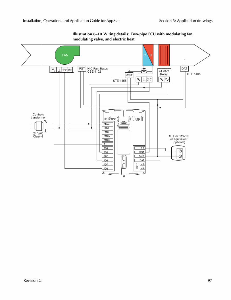
Illustration 6–10 Wiring details: Two-pipe FCU with modulating fan,modulating valve, and electric heat
FAN
24 VACClass-2
0-10VDC
FST N.C Fan StatusCSE-1102
Controlstransformer
STE-1455
STE-1405
DAT
WST
STE-6011W10or equivalent
(optional)
24 VACRelay
SPD SRT
MS/T
P
+B
A
RS
WST
GND
DAT
COM
FAN-L
FAN-M
FAN-H
R
BO4
BO5
GND
AO6
AO8
AO7
24VAC
Installation, Operation, and Application Guide for AppStat Section 6: Application drawings
Revision G 97
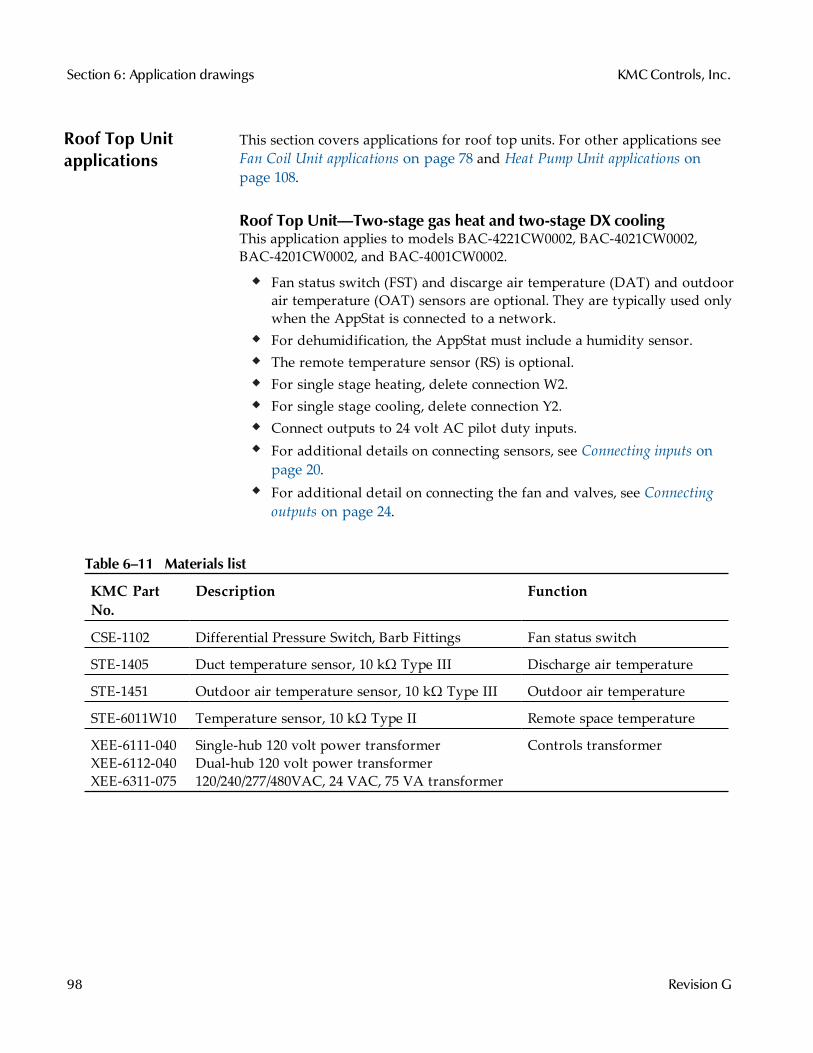
Roof Top Unitapplications
This section covers applications for roof top units. For other applications seeFan Coil Unit applications on page 78 and Heat Pump Unit applications onpage 108.
Roof Top Unit—Two-stage gas heat and two-stage DX coolingThis application applies to models BAC-4221CW0002, BAC-4021CW0002,BAC-4201CW0002, and BAC-4001CW0002.
Fan status switch (FST) and discarge air temperature (DAT) and outdoorair temperature (OAT) sensors are optional. They are typically used onlywhen the AppStat is connected to a network.For dehumidification, the AppStat must include a humidity sensor.The remote temperature sensor (RS) is optional.For single stage heating, delete connection W2.For single stage cooling, delete connection Y2.Connect outputs to 24 volt AC pilot duty inputs.For additional details on connecting sensors, see Connecting inputs onpage 20.For additional detail on connecting the fan and valves, see Connectingoutputs on page 24.
KMC PartNo.
Description Function
CSE-1102 Differential Pressure Switch, Barb Fittings Fan status switch
STE-1405 Duct temperature sensor, 10 kΩ Type III Discharge air temperature
STE-1451 Outdoor air temperature sensor, 10 kΩ Type III Outdoor air temperature
STE-6011W10 Temperature sensor, 10 kΩ Type II Remote space temperature
XEE-6111-040XEE-6112-040XEE-6311-075
Single-hub 120 volt power transformerDual-hub 120 volt power transformer120/240/277/480VAC, 24 VAC, 75 VA transformer
Controls transformer
Table 6–11 Materials list
Section 6: Application drawings KMCControls, Inc.
98 Revision G
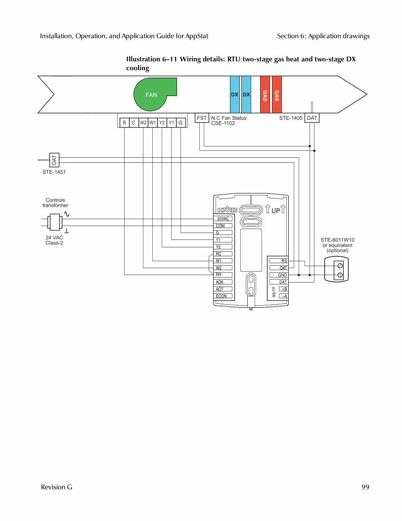
Illustration 6–11 Wiring details: RTU two-stage gas heat and two-stage DXcooling
MS/T
P
+B
A
RS
OAT
GND
DAT
ECON
G
Y1
Y2
RC
W1
W2
RH
AO6
AO7
COM
24VAC
FAN
24 VACClass-2
STE-1451
FSTW2 W1 GY2 Y1CR
N.C Fan StatusCSE-1102
STE-1405
STE-6011W10or equivalent
(optional)
DAT
OA
T
Controlstransformer
GAS
GASDX DX
Installation, Operation, and Application Guide for AppStat Section 6: Application drawings
Revision G 99
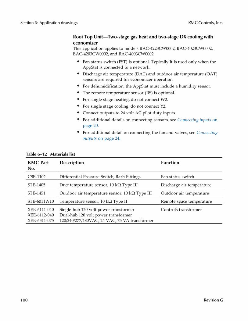
Roof Top Unit—Two-stage gas heat and two-stage DX cooling witheconomizerThis application applies to models BAC-4223CW0002, BAC-4023CW0002,BAC-4203CW0002, and BAC-4003CW0002
Fan status switch (FST) is optional. Typically it is used only when theAppStat is connected to a network.Discharge air temperature (DAT) and outdoor air temperature (OAT)sensors are required for economizer operation.For dehumidification, the AppStat must include a humidity sensor.The remote temperature sensor (RS) is optional.For single stage heating, do not connect W2.For single stage cooling, do not connect Y2.Connect outputs to 24 volt AC pilot duty inputs.For additional details on connecting sensors, see Connecting inputs onpage 20.For additional detail on connecting the fan and valves, see Connectingoutputs on page 24.
KMC PartNo.
Description Function
CSE-1102 Differential Pressure Switch, Barb Fittings Fan status switch
STE-1405 Duct temperature sensor, 10 kΩ Type III Discharge air temperature
STE-1451 Outdoor air temperature sensor, 10 kΩ Type III Outdoor air temperature
STE-6011W10 Temperature sensor, 10 kΩ Type II Remote space temperature
XEE-6111-040XEE-6112-040XEE-6311-075
Single-hub 120 volt power transformerDual-hub 120 volt power transformer120/240/277/480VAC, 24 VAC, 75 VA transformer
Controls transformer
Table 6–12 Materials list
Section 6: Application drawings KMCControls, Inc.
100 Revision G
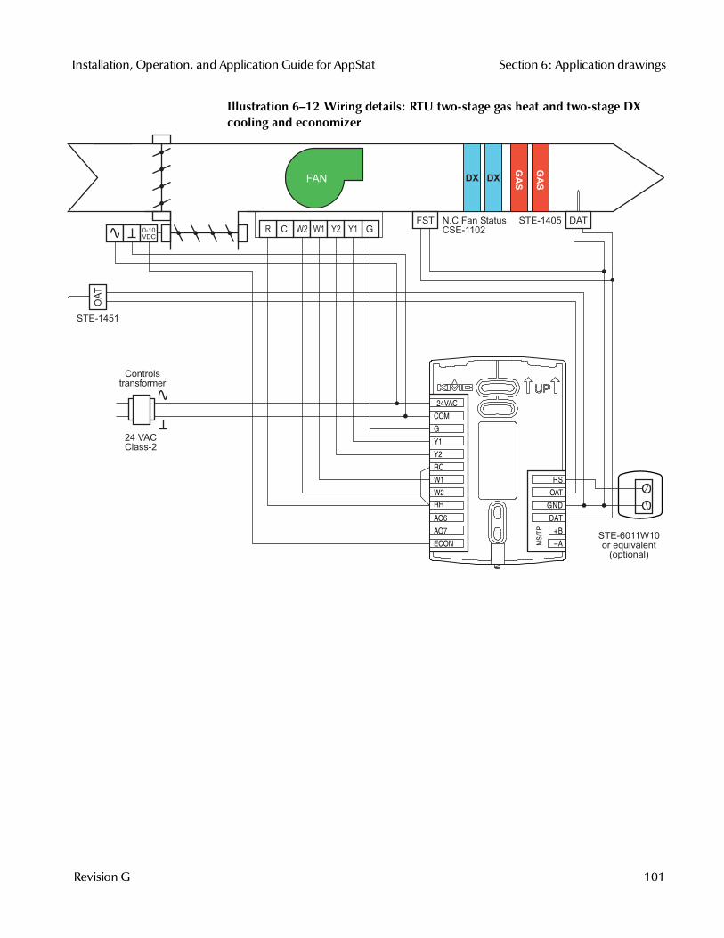
Illustration 6–12 Wiring details: RTU two-stage gas heat and two-stage DXcooling and economizer
MS/T
P
+B
A
RS
OAT
GND
DAT
ECON
G
Y1
Y2
RC
W1
W2
RH
AO6
AO7
COM
24VAC
FAN
24 VACClass-2
FST
GAS
GASDX DX
W2 W1 GY2 Y1CR0-10VDC
STE-1451
N.C Fan StatusCSE-1102
STE-1405
STE-6011W10or equivalent
(optional)
DAT
OA
T
Controlstransformer
Installation, Operation, and Application Guide for AppStat Section 6: Application drawings
Revision G 101
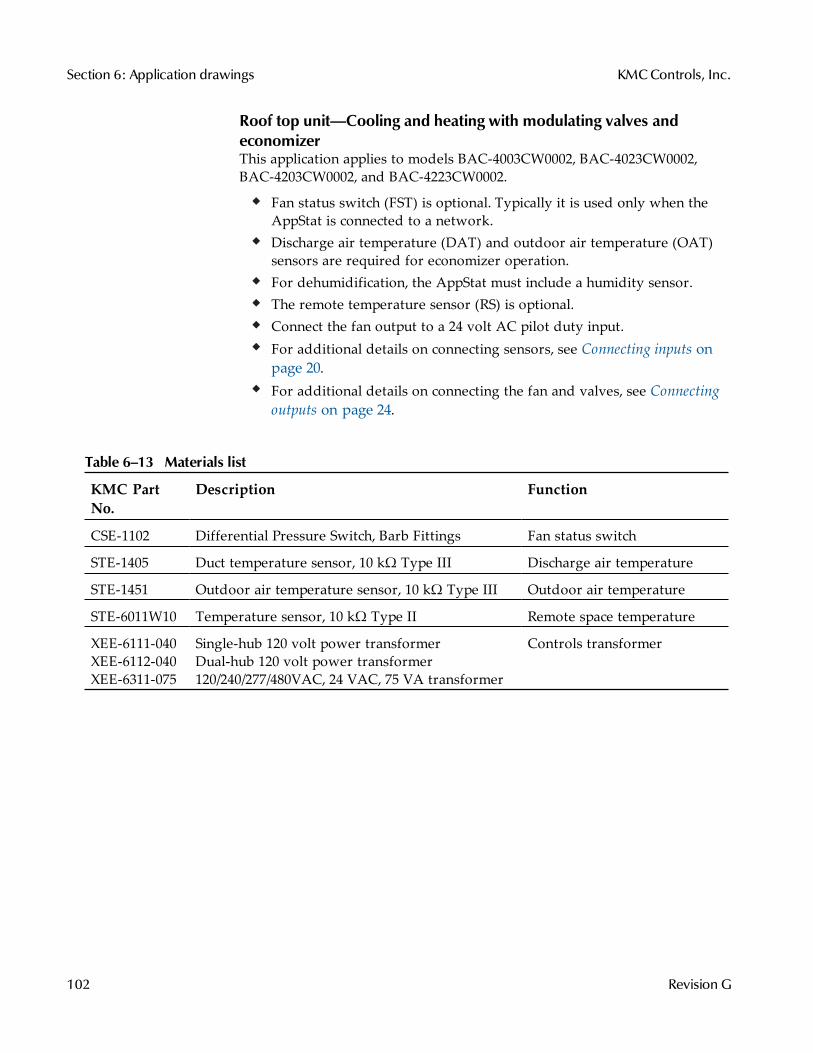
Roof top unit—Cooling and heating with modulating valves andeconomizerThis application applies to models BAC-4003CW0002, BAC-4023CW0002,BAC-4203CW0002, and BAC-4223CW0002.
Fan status switch (FST) is optional. Typically it is used only when theAppStat is connected to a network.Discharge air temperature (DAT) and outdoor air temperature (OAT)sensors are required for economizer operation.For dehumidification, the AppStat must include a humidity sensor.The remote temperature sensor (RS) is optional.Connect the fan output to a 24 volt AC pilot duty input.For additional details on connecting sensors, see Connecting inputs onpage 20.For additional details on connecting the fan and valves, see Connectingoutputs on page 24.
KMC PartNo.
Description Function
CSE-1102 Differential Pressure Switch, Barb Fittings Fan status switch
STE-1405 Duct temperature sensor, 10 kΩ Type III Discharge air temperature
STE-1451 Outdoor air temperature sensor, 10 kΩ Type III Outdoor air temperature
STE-6011W10 Temperature sensor, 10 kΩ Type II Remote space temperature
XEE-6111-040XEE-6112-040XEE-6311-075
Single-hub 120 volt power transformerDual-hub 120 volt power transformer120/240/277/480VAC, 24 VAC, 75 VA transformer
Controls transformer
Table 6–13 Materials list
Section 6: Application drawings KMCControls, Inc.
102 Revision G
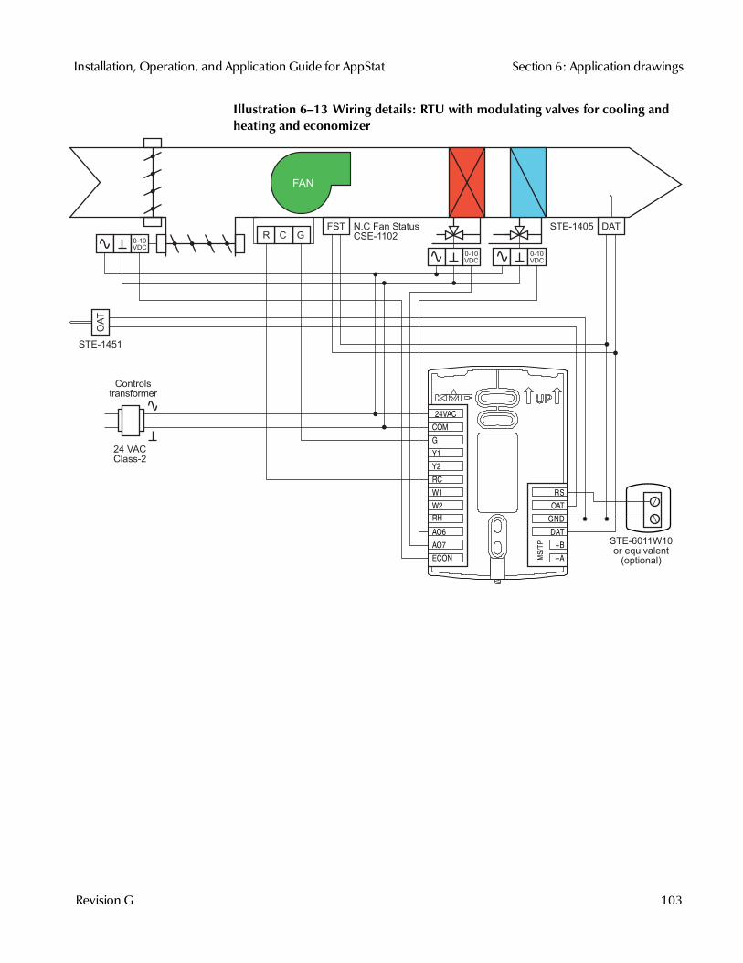
Illustration 6–13 Wiring details: RTU with modulating valves for cooling andheating and economizer
MS/T
P+B
A
RS
OAT
GND
DAT
ECON
G
Y1
Y2
RC
W1
W2
RH
AO6
AO7
COM
24VAC
FAN
24 VACClass-2
0-10VDC
FST
0-10VDC
STE-1451
N.C Fan StatusCSE-1102
STE-1405
STE-6011W10or equivalent
(optional)
DAT
OA
T
GCR0-10VDC
Controlstransformer
Installation, Operation, and Application Guide for AppStat Section 6: Application drawings
Revision G 103

Roof Top Unit—Two-stage gas heat, chilled water cooling withmodulating valve and economizerThis application applies to models BAC-4003CW0002, BAC-4023CW0002,BAC-4203CW0002, and BAC-4223CW0002.
Fan status switch (FST) is optional. Typically it is used only when theAppStat is connected to a network.Discharge air temperature (DAT) and outdoor air temperature (OAT)sensors are required for economizer operation.For dehumidification, the AppStat must include a humidity sensor.The remote temperature sensor (RS) is optional.Connect staged heating and fan outputs to 24 volt AC pilot duty inputs.For single stage heating, do not connect W2.For additional details on connecting sensors, see Connecting inputs onpage 20.For additional details on connecting the fan and valves, see Connectingoutputs on page 24.
KMC PartNo.
Description Function
CSE-1102 Differential Pressure Switch, Barb Fittings Fan status switch
STE-1405 Duct temperature sensor, 10 kΩ Type III Discharge air temperature
STE-1451 Outdoor air temperature sensor, 10 kΩ Type III Outdoor air temperature
STE-6011W10 Temperature sensor, 10 kΩ Type II Remote space temperature
XEE-6111-040XEE-6112-040XEE-6311-075
Single-hub 120 volt power transformerDual-hub 120 volt power transformer120/240/277/480VAC, 24 VAC, 75 VA transformer
Controls transformer
Table 6–14 Materials list
Section 6: Application drawings KMCControls, Inc.
104 Revision G

Illustration 6–14 Wiring details: RTU with two-stage gas heat, chilled watercooling with economizer
MS/T
P
+B
A
RS
OAT
GND
DAT
ECON
G
Y1
Y2
RC
W1
W2
RH
AO6
AO7
COM
24VAC
GASFAN
24 VACClass-2
FST
GAS
W2 W1 GCR
0-10VDC
0-10VDC
STE-1451
N.C Fan StatusCSE-1102
STE-1405
STE-6011W10or equivalent
(optional)
DAT
OA
T
Controlstransformer
Installation, Operation, and Application Guide for AppStat Section 6: Application drawings
Revision G 105
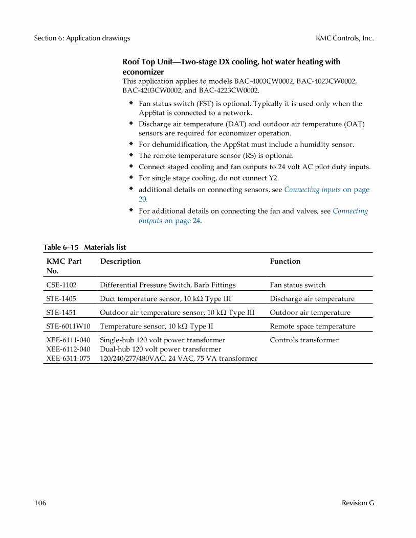
Roof Top Unit—Two-stage DX cooling, hot water heating witheconomizerThis application applies to models BAC-4003CW0002, BAC-4023CW0002,BAC-4203CW0002, and BAC-4223CW0002.
Fan status switch (FST) is optional. Typically it is used only when theAppStat is connected to a network.Discharge air temperature (DAT) and outdoor air temperature (OAT)sensors are required for economizer operation.For dehumidification, the AppStat must include a humidity sensor.The remote temperature sensor (RS) is optional.Connect staged cooling and fan outputs to 24 volt AC pilot duty inputs.For single stage cooling, do not connect Y2.additional details on connecting sensors, see Connecting inputs on page20.For additional details on connecting the fan and valves, see Connectingoutputs on page 24.
KMC PartNo.
Description Function
CSE-1102 Differential Pressure Switch, Barb Fittings Fan status switch
STE-1405 Duct temperature sensor, 10 kΩ Type III Discharge air temperature
STE-1451 Outdoor air temperature sensor, 10 kΩ Type III Outdoor air temperature
STE-6011W10 Temperature sensor, 10 kΩ Type II Remote space temperature
XEE-6111-040XEE-6112-040XEE-6311-075
Single-hub 120 volt power transformerDual-hub 120 volt power transformer120/240/277/480VAC, 24 VAC, 75 VA transformer
Controls transformer
Table 6–15 Materials list
Section 6: Application drawings KMCControls, Inc.
106 Revision G
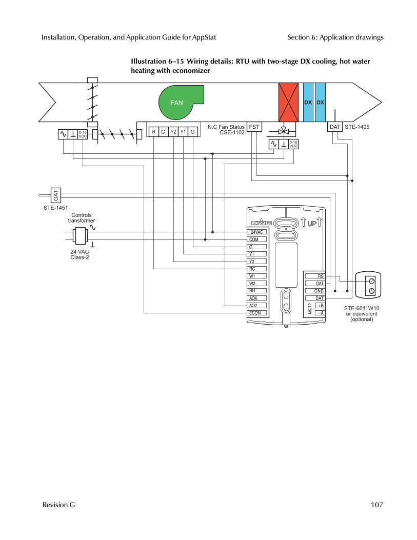
Illustration 6–15 Wiring details: RTU with two-stage DX cooling, hot waterheating with economizer
MS/T
P
+B
A
RS
OAT
GND
DAT
ECON
G
Y1
Y2
RC
W1
W2
RH
AO6
AO7
COM
24VAC
FAN
24 VACClass-2
FSTY2 Y1 GCR0-10
VDC
STE-1451
N.C Fan StatusCSE-1102
STE-1405
STE-6011W10or equivalent
(optional)
DAT
OA
T
Controlstransformer
0-10VDC
DX DX
Installation, Operation, and Application Guide for AppStat Section 6: Application drawings
Revision G 107
Heat Pump Unitapplications
This section covers applications for fan coil units. For other applications seeFan Coil Unit applications on page 78 and Roof Top Unit applications on page98.
Heat pump unit—Three heat, two coolThis application applies to models BAC-4001CW0003, BAC-4021CW0003,BAC-4201CW0003, and BAC-4221CW0003.
Fan status switch (FST) and discharge air temperature sensor (DAT) areoptional. They are typically used only when the AppStat is connected toa network.The outdoor air temperature sensor (OAT) is required for compressorlockout based on outside air temperature.For dehumidification, the AppStat must include a humidity sensor.Auxiliary heat is required for dehumidification.The remote temperature sensor (RS) is optional.For single compressor installations, delete the Y2 connection.If auxiliary heat is not required delete the AUX/E connection.Connect outputs only to 24 volt AC pilot duty inputs.For additional details on connecting sensors, see Connecting inputs onpage 20.
KMC PartNo.
Description Function
CSE-1102 Differential Pressure Switch, Barb Fittings Fan status switch
STE-1405 Duct temperature sensor, 10 kΩ Type III Discharge air temperature
STE-1451 Outdoor air temperature sensor, 10 kΩ Type III Outdoor air temperature
STE-6011W10 Temperature sensor, 10 kΩ Type II Remote space temperature
XEE-6111-040XEE-6112-040XEE-6311-075
Single-hub 120 volt power transformerDual-hub 120 volt power transformer120/240/277/480VAC, 24 VAC, 75 VA transformer
Controls transformer
Table 6–16 Materials list
Section 6: Application drawings KMCControls, Inc.
108 Revision G

Illustration 6–16 Wiring details: HPU—Three heat, two cool
MS/T
P
+B
A
RS
OAT
GND
DAT
ECON
G
Y1
Y2
RC
O/B
AUX/E
AO6
AO7
COM
24VAC
RH
24 VACClass-2
FAN
AUX O/B GY2 Y1 C RFST
COM
PRESSOR
COM
PRESSOR
N.C Fan StatusCSE-1102
STE-1405DAT
Controlstransformer
STE-6011W10or equivalent
(optional)
STE-1451
OA
T
Installation, Operation, and Application Guide for AppStat Section 6: Application drawings
Revision G 109
Heat Pump Unit—Three heat, two cool and economizerThis application applies to models BAC-4003CW0003, BAC-4023CW0003,BAC-4203CW0003, and BAC-4223CW0003.
Heat pump unit installation notes
Fan status switch (FST) and discharge air temperature sensor (DAT) areoptional. They are typically used only when the AppStat is connected toa network.The outdoor air temperature sensor (OAT) is required for compressorlockout based on outside air temperature.For dehumidification, the AppStat must include a humidity sensor.Auxiliary heat is required for dehumidification.The remote temperature sensor (RS) is optional.For single compressor installations, delete the Y2 connection.If auxiliary heat is not required delete the AUX/E connection.Connect outputs only to 24 volt AC pilot duty inputs.Economizer (ECON) input is 0-10 volts DC.For additional details on connecting sensors, see Connecting inputs onpage 20.
KMC PartNo.
Description Function
CSE-1102 Differential Pressure Switch, Barb Fittings Fan status switch
STE-1405 Duct temperature sensor, 10 kΩ Type III Discharge air temperature
STE-1451 Outdoor air temperature sensor, 10 kΩ Type III Outdoor air temperature
STE-6011W10 Temperature sensor, 10 kΩ Type II Remote space temperature
XEE-6111-040XEE-6112-040XEE-6311-075
Single-hub 120 volt power transformerDual-hub 120 volt power transformer120/240/277/480VAC, 24 VAC, 75 VA transformer
Controls transformer
Table 6–17 Materials list
Section 6: Application drawings KMCControls, Inc.
110 Revision G
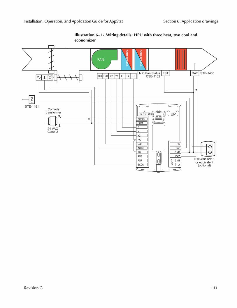
Illustration 6–17 Wiring details: HPU with three heat, two cool andeconomizer
MS/T
P
+B
A
RS
OAT
GND
DAT
ECON
G
Y1
Y2
RC
O/B
AUX/E
AO6
AO7
COM
24VAC
RH
24 VACClass-2
FAN
AUX O/B GY2 Y1 C RFST
0-10VDC
COM
PRESSOR
COM
PRESSOR
N.C Fan StatusCSE-1102
STE-1405DAT
Controlstransformer
STE-6011W10or equivalent
(optional)
STE-1451
OA
T
Installation, Operation, and Application Guide for AppStat Section 6: Application drawings
Revision G 111

Section 6: Application drawings KMCControls, Inc.
112 Revision G
Sec t ion 7: Sys tem integ rat ion
Topics in this section cover integrating AppStat controllers into abuilding automation network. These are advanced topics for controltechnicians and engineers.
The AppStat can function as a standalone controller or it can be connected toa BACnet MS/TP network. The topics in this section are reference material forcontrol technicians or engineers that will be installing and setting up anAppStat that is connected to a network.
In addition to the information in this section, you will also need the followinginformation.
Detailed plans and drawings for the building automation system.Information about the facility LAN including routers, switches, andnetwork firewalls.Application Note AN0404A Planning BACnet Networks This document isavailable from the KMC Controls partners web portal.
Topics in this section
BACnet objects on page 114Connecting to an MS/TP network on page 121
Installation, Operation, and Application Guide for AppStat
Revision G 113
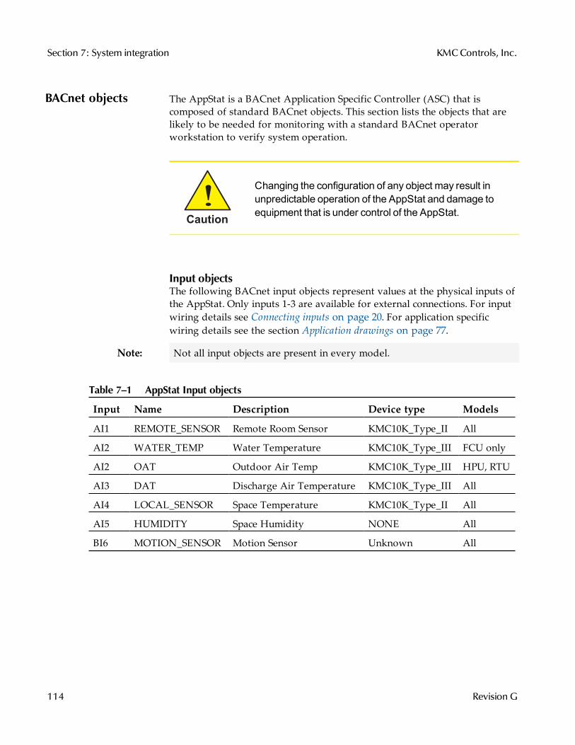
BACnet objects The AppStat is a BACnet Application Specific Controller (ASC) that iscomposed of standard BACnet objects. This section lists the objects that arelikely to be needed for monitoring with a standard BACnet operatorworkstation to verify system operation.
Caution
Changing the configuration of any object may result inunpredictable operation of the AppStat and damage toequipment that is under control of the AppStat.
Input objectsThe following BACnet input objects represent values at the physical inputs ofthe AppStat. Only inputs 1-3 are available for external connections. For inputwiring details see Connecting inputs on page 20. For application specificwiring details see the section Application drawings on page 77.
Note: Not all input objects are present in every model.
Input Name Description Device type Models
AI1 REMOTE_SENSOR Remote Room Sensor KMC10K_Type_II All
AI2 WATER_TEMP Water Temperature KMC10K_Type_III FCU only
AI2 OAT Outdoor Air Temp KMC10K_Type_III HPU, RTU
AI3 DAT Discharge Air Temperature KMC10K_Type_III All
AI4 LOCAL_SENSOR Space Temperature KMC10K_Type_II All
AI5 HUMIDITY Space Humidity NONE All
BI6 MOTION_SENSOR Motion Sensor Unknown All
Table 7–1 AppStat Input objects
Section 7: System integration KMCControls, Inc.
114 Revision G
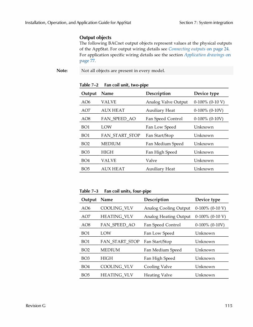
Output objectsThe following BACnet output objects represent values at the physical outputsof the AppStat. For output wiring details see Connecting outputs on page 24.For application specific wiring details see the section Application drawings onpage 77.
Note: Not all objects are present in every model.
Output Name Description Device type
AO6 VALVE Analog Valve Output 0-100% (0-10 V)
AO7 AUX HEAT Auxiliary Heat 0-100% (0-10V)
AO8 FAN_SPEED_AO Fan Speed Control 0-100% (0-10V)
BO1 LOW Fan Low Speed Unknown
BO1 FAN_START_STOP Fan Start/Stop Unknown
BO2 MEDIUM Fan Medium Speed Unknown
BO3 HIGH Fan High Speed Unknown
BO4 VALVE Valve Unknown
BO5 AUX HEAT Auxiliary Heat Unknown
Table 7–2 Fan coil unit, two-pipe
Output Name Description Device type
AO6 COOLING_VLV Analog Cooling Output 0-100% (0-10 V)
AO7 HEATING_VLV Analog Heating Output 0-100% (0-10 V)
AO8 FAN_SPEED_AO Fan Speed Control 0-100% (0-10V)
BO1 LOW Fan Low Speed Unknown
BO1 FAN_START_STOP Fan Start/Stop Unknown
BO2 MEDIUM Fan Medium Speed Unknown
BO3 HIGH Fan High Speed Unknown
BO4 COOLING_VLV Cooling Valve Unknown
BO5 HEATING_VLV Heating Valve Unknown
Table 7–3 Fan coil units, four-pipe
Installation, Operation, and Application Guide for AppStat Section 7: System integration
Revision G 115
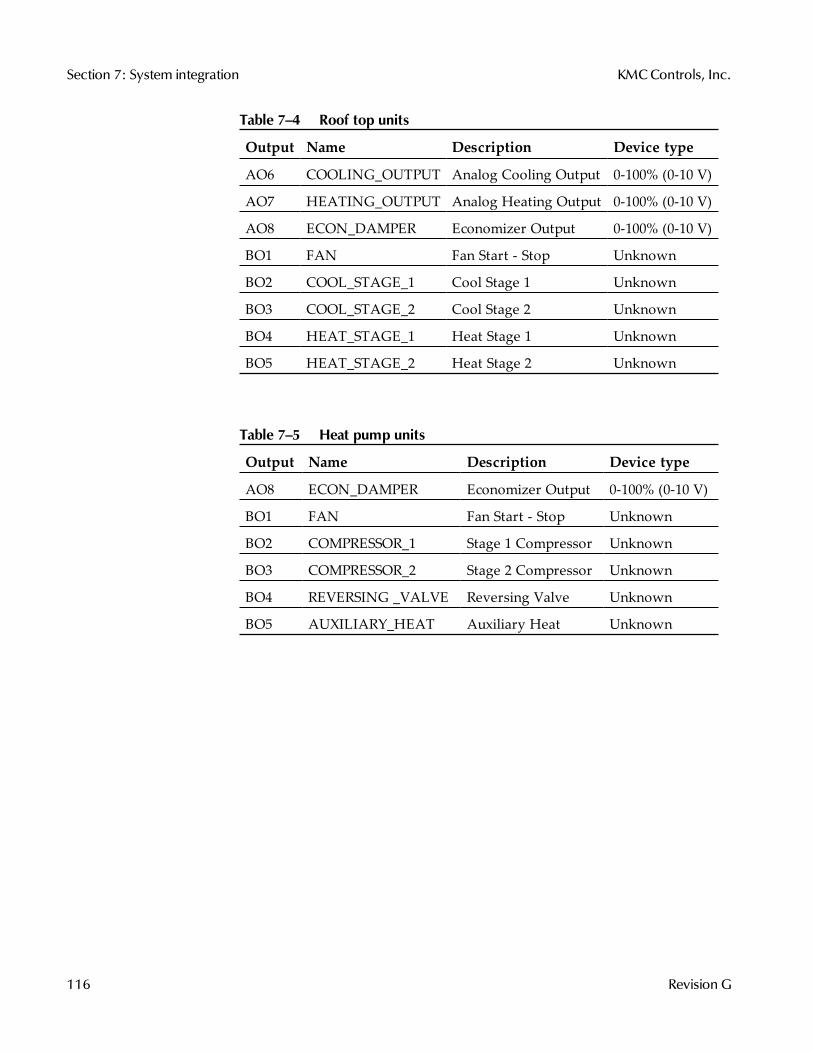
Output Name Description Device type
AO6 COOLING_OUTPUT Analog Cooling Output 0-100% (0-10 V)
AO7 HEATING_OUTPUT Analog Heating Output 0-100% (0-10 V)
AO8 ECON_DAMPER Economizer Output 0-100% (0-10 V)
BO1 FAN Fan Start - Stop Unknown
BO2 COOL_STAGE_1 Cool Stage 1 Unknown
BO3 COOL_STAGE_2 Cool Stage 2 Unknown
BO4 HEAT_STAGE_1 Heat Stage 1 Unknown
BO5 HEAT_STAGE_2 Heat Stage 2 Unknown
Table 7–4 Roof top units
Output Name Description Device type
AO8 ECON_DAMPER Economizer Output 0-100% (0-10 V)
BO1 FAN Fan Start - Stop Unknown
BO2 COMPRESSOR_1 Stage 1 Compressor Unknown
BO3 COMPRESSOR_2 Stage 2 Compressor Unknown
BO4 REVERSING _VALVE Reversing Valve Unknown
BO5 AUXILIARY_HEAT Auxiliary Heat Unknown
Table 7–5 Heat pump units
Section 7: System integration KMCControls, Inc.
116 Revision G
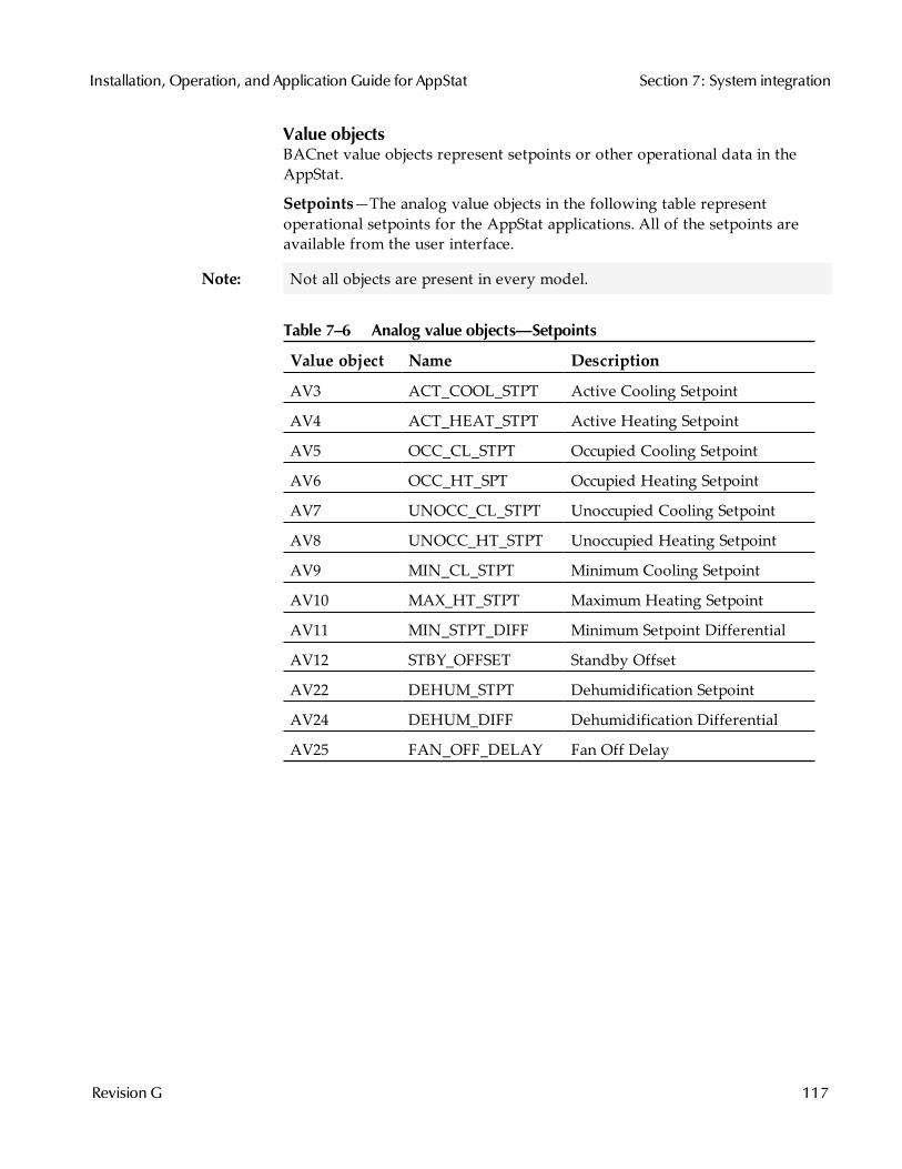
Value objectsBACnet value objects represent setpoints or other operational data in theAppStat.
Setpoints—The analog value objects in the following table representoperational setpoints for the AppStat applications. All of the setpoints areavailable from the user interface.
Note: Not all objects are present in every model.
Value object Name Description
AV3 ACT_COOL_STPT Active Cooling Setpoint
AV4 ACT_HEAT_STPT Active Heating Setpoint
AV5 OCC_CL_STPT Occupied Cooling Setpoint
AV6 OCC_HT_SPT Occupied Heating Setpoint
AV7 UNOCC_CL_STPT Unoccupied Cooling Setpoint
AV8 UNOCC_HT_STPT Unoccupied Heating Setpoint
AV9 MIN_CL_STPT Minimum Cooling Setpoint
AV10 MAX_HT_STPT Maximum Heating Setpoint
AV11 MIN_STPT_DIFF Minimum Setpoint Differential
AV12 STBY_OFFSET Standby Offset
AV22 DEHUM_STPT Dehumidification Setpoint
AV24 DEHUM_DIFF Dehumidification Differential
AV25 FAN_OFF_DELAY Fan Off Delay
Table 7–6 Analog value objects—Setpoints
Installation, Operation, and Application Guide for AppStat Section 7: System integration
Revision G 117
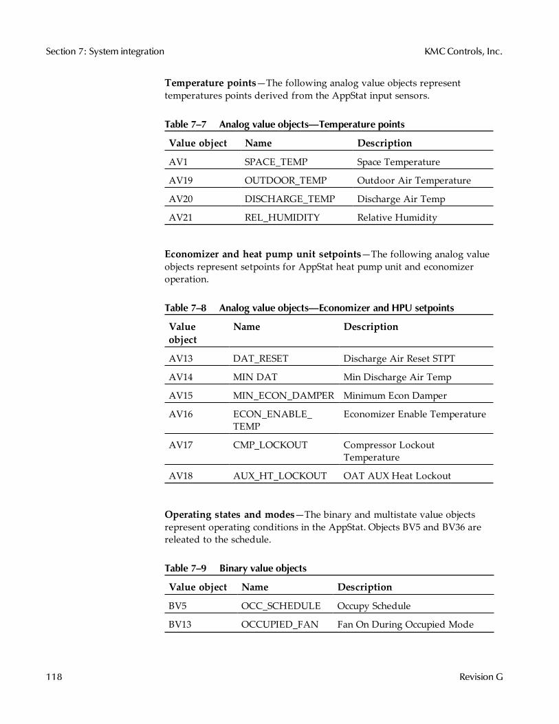
Temperature points—The following analog value objects representtemperatures points derived from the AppStat input sensors.
Value object Name Description
AV1 SPACE_TEMP Space Temperature
AV19 OUTDOOR_TEMP Outdoor Air Temperature
AV20 DISCHARGE_TEMP Discharge Air Temp
AV21 REL_HUMIDITY Relative Humidity
Table 7–7 Analog value objects—Temperature points
Economizer and heat pump unit setpoints—The following analog valueobjects represent setpoints for AppStat heat pump unit and economizeroperation.
Valueobject
Name Description
AV13 DAT_RESET Discharge Air Reset STPT
AV14 MIN DAT Min Discharge Air Temp
AV15 MIN_ECON_DAMPER Minimum Econ Damper
AV16 ECON_ENABLE_TEMP
Economizer Enable Temperature
AV17 CMP_LOCKOUT Compressor LockoutTemperature
AV18 AUX_HT_LOCKOUT OAT AUX Heat Lockout
Table 7–8 Analog value objects—Economizer and HPU setpoints
Operating states and modes—The binary and multistate value objectsrepresent operating conditions in the AppStat. Objects BV5 and BV36 arereleated to the schedule.
Value object Name Description
BV5 OCC_SCHEDULE Occupy Schedule
BV13 OCCUPIED_FAN Fan On During Occupied Mode
Table 7–9 Binary value objects
Section 7: System integration KMCControls, Inc.
118 Revision G
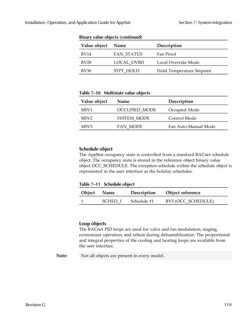
Value object Name Description
BV14 FAN_STATUS Fan Proof
BV28 LOCAL_OVRD Local Override Mode
BV36 STPT_HOLD Hold Temperature Setpoint
Binary value objects (continued)
Value object Name Description
MSV1 OCCUPIED_MODE Occupied Mode
MSV2 SYSTEM_MODE Control Mode
MSV3 FAN_MODE Fan Auto-Manual Mode
Table 7–10 Multistate value objects
Schedule objectThe AppStat occupancy state is controlled from a standard BACnet scheduleobject. The occupancy state is stored in the reference object binary valueobject OCC_SCHEDULE. The exception schedule within the schedule object isrepresented in the user interface as the holiday schedules.
Object Name Description Object reference
1 SCHED_1 Schedule #1 BV5 (OCC_SCHEDULE)
Table 7–11 Schedule object
Loop objectsThe BACnet PID loops are used for valve and fan modulation, staging,economizer operation, and reheat during dehumidification. The proportionaland integral properties of the cooling and heating loops are available fromthe user interface.
Note: Not all objects are present in every model.
Installation, Operation, and Application Guide for AppStat Section 7: System integration
Revision G 119
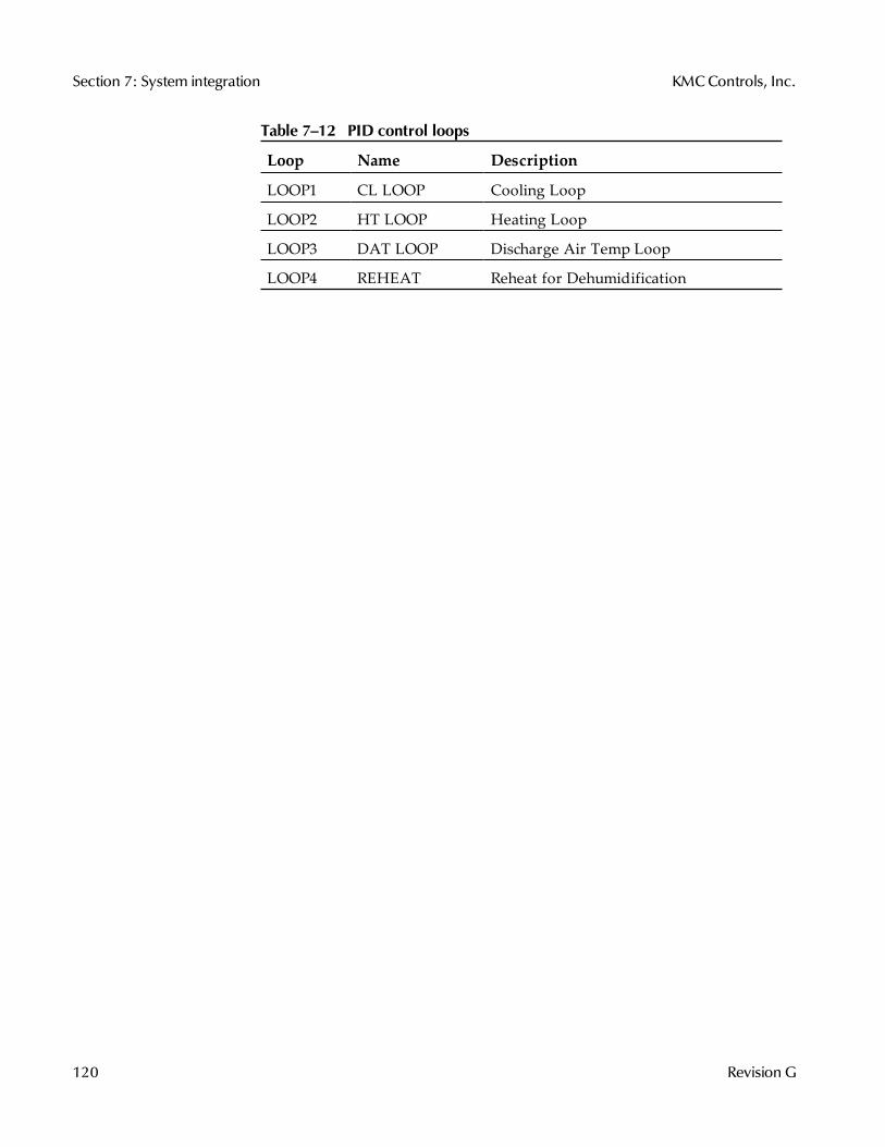
Loop Name Description
LOOP1 CL LOOP Cooling Loop
LOOP2 HT LOOP Heating Loop
LOOP3 DAT LOOP Discharge Air Temp Loop
LOOP4 REHEAT Reheat for Dehumidification
Table 7–12 PID control loops
Section 7: System integration KMCControls, Inc.
120 Revision G
Connecting to anMS/TP network
Before connecting the AppStat to a BACnet MS/TP network, configure thenetwork properties. See the topic Set up communications on page 43 for theprocedure to set the following:
Device instanceMAC addressBaud
Use the following principles when wiring the AppStat to an MS/TP network:
Connect no more than 128 addressable BACnet devices to one MS/TPnetwork. The devices can be any mix of AppStat controllers, otherBACnet controllers, or BACnet routers.To prevent network traffic bottlenecks, limit the MS/TP network size to60 controllers.Use 18 gauge, twisted pair, shielded cable with capacitance of no morethan 51 picofarads per foot for all network wiring. Belden cable model#82760 meets the cable requirements.Connect the -A terminal in parallel with all other - terminals.Connect the +B terminal in parallel with all other + terminals.Connect the shield to an earth ground at one end only.Use a KMD-5575 repeater between every 32 MS/TP devices or if the totalcable length will exceed 4000 feet (1220 meters). Use no more than fourrepeaters per MS/TP network.Place a KMD-5567 surge suppressor in the cable where it exits a building.
For more information on installing HVAC system controllers, see ApplicationNote AN0404A, Planning BACnet Networks.
Installation, Operation, and Application Guide for AppStat Section 7: System integration
Revision G 121
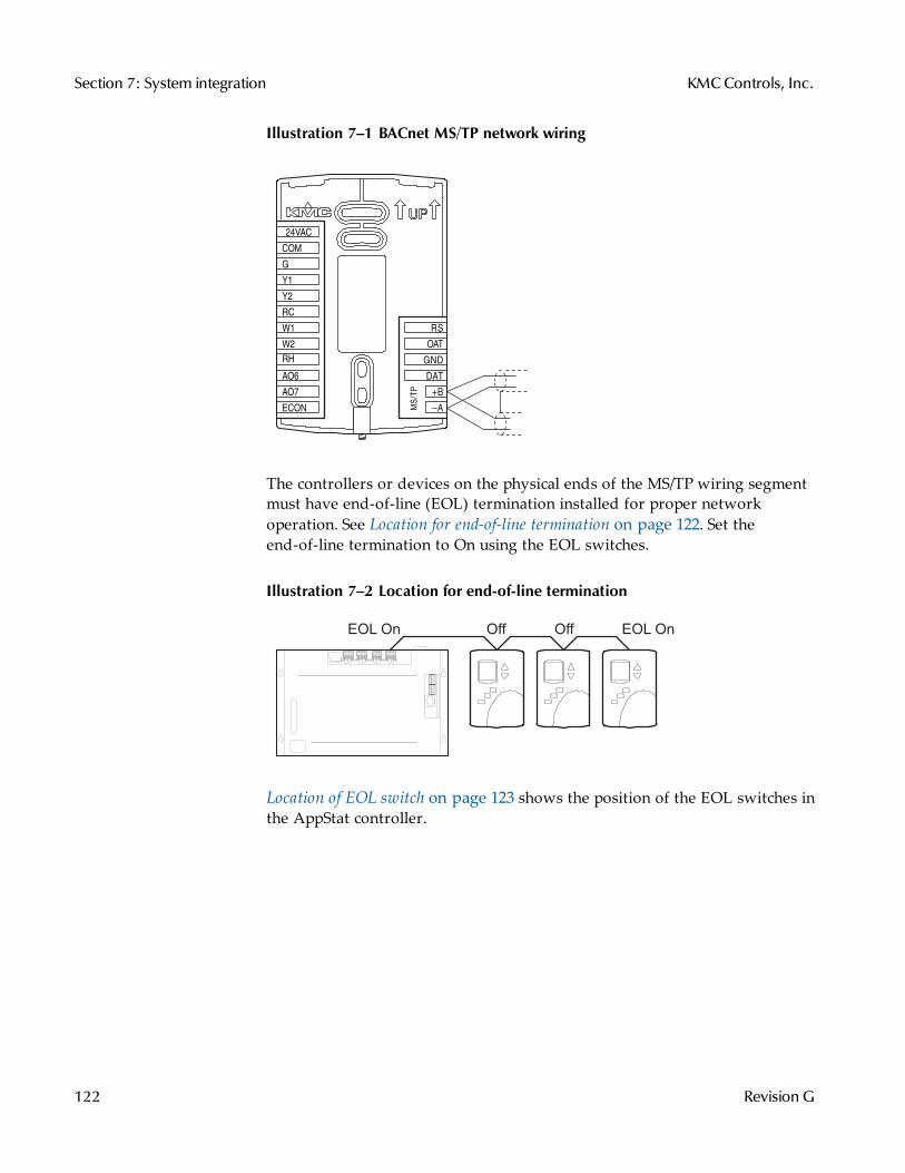
Illustration 7–1 BACnet MS/TP network wiring
MS/T
P
+B
A
RS
OAT
GND
DAT
ECON
G
Y1
Y2
RC
W1
W2
RH
AO6
AO7
COM
24VAC
The controllers or devices on the physical ends of the MS/TP wiring segmentmust have end-of-line (EOL) termination installed for proper networkoperation. See Location for end-of-line termination on page 122. Set theend-of-line termination to On using the EOL switches.
Illustration 7–2 Location for end-of-line termination
EOL On EOL OnOff Off
Location of EOL switch on page 123 shows the position of the EOL switches inthe AppStat controller.
Section 7: System integration KMCControls, Inc.
122 Revision G
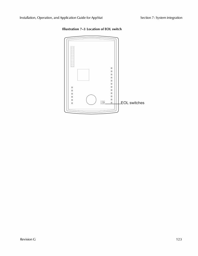
Illustration 7–3 Location of EOL switch
EOL switches
Installation, Operation, and Application Guide for AppStat Section 7: System integration
Revision G 123
Section 7: System integration KMCControls, Inc.
124 Revision G
Index
Aaccuracyhumidity 9temperature 9
analog value objects 117application drawingsfan coil unit 78heat pump unit 108roof top unit 98
auxillary heatfan coil units,see electric heat 72heat pump units 75
BBACnetbaud 43device instance 43input objects 114loop objects 119MAC address 43network specification 9network wiring 121output objects 115PID loops 70schedule object 119time 45value objects 117
baud 43binary value objects 117button operation 31
Ccalibrate space temperature input 60Celsius 36changeover, heating and cooling 68clock 45communicationsBACnet specification 9set up 43
Ddaily schedule 47
date, setting 45Daylight Saving Time 45dehumidificaion sequence 68device instance 43dimensions 11dimming the display 69discharge air temperaturesensor wiring 21sequence of operation 69
displayblanking 69clock 69dimensions 8dimming 69icons 31parts of 31
Eeconomizeroperation 75setpoint objects 117wiring 28
electric heatfan coil unit 72heat pump unit 75
environmental limits 10EOL switches 121
FFahrenheit 36fan coil unitapplication drawings 78electric heat 72fan sequence 72model numbers 13set up 50valve sequence 70
fan sequencefan coil unit 72heat pump unit 74roof top unit 74
fan statussequence of operation 68switch wiring 21
Installation, Operation, and Application Guide for AppStat
Revision G 125
Hheat pump unitapplication drawings 108auxillary heat 75electic heat 75fan sequence 74model numbers 13sequence of operation 75set up 56
holiday schedule 47
Iicons 31inputs 20BACnet objects 114discharge air temperature 21fan status switch 21outside air temperature 23remote space temperature 20water temperature sensor 22
installing 17
Lloops See PID loops
MMAC address 43maintenance 29metric display 36model numbers 13motion sensingplanning 17range 11sequence of operation 67
MS/TPaddressing 43EOL switches 121MAC address 121wiring 121
multistate value objects 117
Nnetworkbaud 43communications 43
device instance 43Mac 43specifications 9termination 121wiring 121
Ooccupancy schedule 47occupied setpoints 41operation 31outputs 24BACnet objects 115economizer 28modulating fan 25modulating valves 27on/off valves 26three-speed fan 24
PpasswordsPassword 1 35Password 2 40setting and changing 60user 34-35
PID loopsadjusting 60BACnet object 119sequence of operation 70
powerspecifications 10wiring 28
Rregulatory approvals 10remote space temperaturecalibrate 60sensor wiring 20sequence of operation 69
roof top unitapplication drawings 98fan sequence 74model numbers 13modulating cooling and heating 73set up 53staged cooling and heating 73
Index KMCControls, Inc.
126 Revision G
Ssafety 16schedulesBACnet object 119sequence of operation 68setting 47
security 60sequence of operation 65automatic changeover 68dehumidification 68discharge air temperature 69display and backlight 69economizer 75electric heatfan coil unit 72heat pump unit 75
fan coil valves 70fan status 68heat pump fans 74heat pump staged cooling and heating 74heat pump unit 75motion sensing 67occupancy 67PID loops 70remote space temperature sensing 69reversing valve 75roof top fans 74roof top modulating valves 73roof top staged cooling and heating 74schedules 68setpoints 66space temperature 69standby 67temperature sensing 69water temperature sensing 69
setpointscooling 35differential 41heating 35limits 66minimum and maximum 41occupied 41sequence 66temperature 66
unoccupied 41softkey bar 31space temperature sensingcalibrate 60remote sensor wiring 20sequence of operation 69
specifications 8dimensions 11environmental limits 10humidity accuracy 9inputs 8motion sensing 11MS/TP network 9outputs 8power 10temperature accuracy 9user interface 8
staged cooling and heatingfan coil sequence 70heat pump sequence 74roof top unit sequence 74
TtemperatureBACnet objects 114sensing 69
termination, MS/TP 121time, setting 45
Uunoccupied setpoints 41user interface 8user password 34UTC offset 45
Wwater temperature sensorsensor wiring 22sequence of operation 69
wiringfan coil units 78heat pump unit 108inputs 20MS/TP network 121outputs 24
Installation, Operation, and Application Guide for AppStat Index
Revision G 127
power 28roof top unit 98rough-in 18
Index KMCControls, Inc.
128 Revision G
Recommended


![Ch 2: Probability - University of Akrongozips.uakron.edu/~nmimoto/461/AppStat-02.pdf · Summer 2017 UAkron Dept. of Stats [3470 : 461/561] Applied Statistics Ch 2: Probability Contents](https://img.pdfslide.net/doc/110x75/5a90570e7f8b9a78648e0da7/ch-2-probability-university-of-nmimoto461appstat-02pdfsummer-2017-uakron-dept.jpg)