INSTRUCTIONS GEI--31094J
INSTANTANEOUS OVERCURRENT AND VOLTAGE RELAYS
TYPES PJC and PJV IN DRAWOUT CASE
GENERAL e ELECTRIC
www . El
ectric
alPar
tMan
uals
. com
GEI-31094 Instantaneous Relays Types PJC and PJV
TiME-CURRENT CURVES FOR CONTACTS OF PJG R ELAY
.32 '
\ .06 28 _a_ _b_ \ WIPE 3/64. 3/64. r-- 24
GAP 3/64. 3/64" \ TRAVEL 9/64" 9/64" 20
CLOSING OF "e" CONTACT
�- v / (/) �� � / �OPENING OF "b" CONTACT 0
.04 0 ;z c - u w (/)
0
\. _L .01 Kx_ � �
0 5
2
z 16 0 ' "-... / u w 1'--. (/) - 12 _J ""' V' r--_J 1---r-:i 8 ._ -r--� r--!---4
0 t 2 .3 4 I TIMES PICK-UP
VCLOSING TIME OF "a"CONTACT
r--� --lL: /
10 I
.3'1 .32 .30 28 26 "' 2'1 0
z 0 22 u ... "' 20 .... .... 18
VOPENING TIME OF "b"CONTACT
J •
15 20 25 31 35 I TIMES P ICK-UP
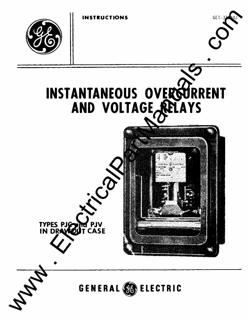
Fig. 1 Time-Curretrt Curves For Type PJC Relays
P.JV RELAY
DROPOUT TIME CURVE PICKUP • 100 VOLTS •-c INITIAL VOLTAGE 115 VOLTS •-c VOLTAGE IS DECREASED SUDDENLY fROW 115 VOLTS •-c TO PER CENT Of PICK Ul' VOLTAGE SHOWN BELOW. ..1 /_
CONTACT ./ , "CLOSING �
TIME /
410
J I /_ I
-
ll ONE CYCLE 160 CYCLE SASISI - :;;;��"" L"_ --r- - r- - f-- -r--- r-- -- r--.. 16 -"' H
a ,_ 12
10 8 6 'I
0
-� J L CONTACT ...,. v OPEN lNG-�
TillE _.,...,. V" -�
10 20 )0 1!0 bo )0 80
fiNAL VOL UGE
Fl g. 2 Dropout- Tille Curves For Type PJY Relay
90 100
r---5
45 50
.. II) > 0 u
.� u.
N .ri! u.
www . El
ectric
alPar
tMan
uals
. com
INSTANTANEOUS OVERCURRENT AND VOLTAGE RELAYS
TYPES PJC AND PJV INTRODUCTION
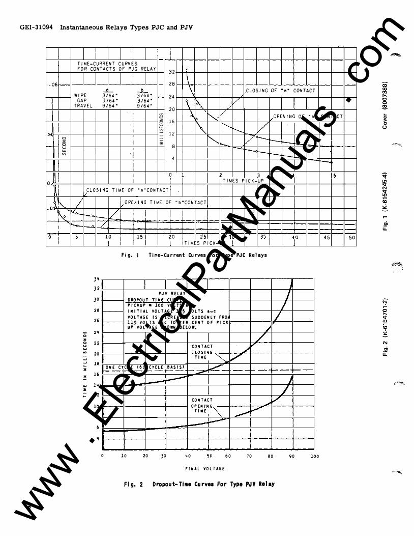
APPLICATION
* The Type PJC and Type PJV plunger relays are designed for general service. These relays are non-directional and instantaneous when in operation.
TARGET AND SEAL-IN UNIT
TABLE I ,.--- 2 Amp Tap
Carry-Tripping Duty 30 Amps Carry Continuously 3 Amps D-C Resistance 0.13 Ohms Impedance (60 Cycles) 0.53 Ohms
CONTACT
0.2 Amp Tap
5 Amps 0.3 Amps 7 Ohms 52 Ohms
The Type PJC relay is normally used for over-current protection of feeder circuits. When used in conjunction with thermal or time-overcurrent relays, it can be used to protect a motor against very high currents since it will operate before the main relays respond. The Type PJC relay is also used for other current-control functions. The a-c relays are applicable where continuous operation in the pick-up position is not required.
The carrying rating of the contacts is 5 amperes continuously or 30 amperes for trippingo The interrupting ratings of resistive loads are given in Table II.
CHARACTERISTICS
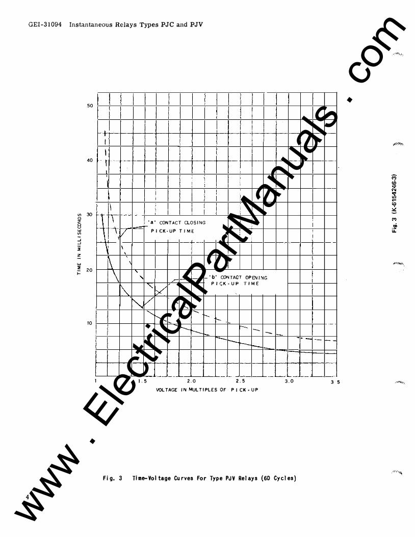
The time-current and time-voltage curves are shown in Figs. 1, 2, and 3 respectively.
The pickuJl of the Type PJC relays without taps is 1/3 to 1-1/3 of the continuous rating, up to and including the 12 ampere rating. Refer to the data given under BURDENS for ratings higher than 12 amperes and tapped coils. The pickup of the Type PJV relays is adjustable from 61 to 139 per cent of rating.
The a-c dropout is approximately 90 to 95 per cent of pickup at any point within the calibrating range when using the contact arrangement of one "a" and one "b". The d-e dropout is 60 to 90 per cent of pickup.
COIL
Type PJC
RATINGS
Tapped - 5 and 10 amperes
TABLE ll D-C
v ·2� I
4� I 125 250 115
A 1 0.3 5 BURDENS
CURRENT RELAYS
TABLE lli
Rated Cal. VA at 5 W at 5 Amps Range Amps Amps 60 eye. 60 eye.
1.5 0.5-2 165 55 3 1-4 41 12.7 5 2-50 9.6 5.3 6 2-8 11.5 3.56 10 4-100 2.65 0.8 12 4-16 2.65 0.8 25 10-40 0.4 0.125 25 20-80 0.1 0.03 25 40-160 0.025 0.008
A-C
230 1460 2 1
W at 5 Amps
d-e
31 7.6 1.98 2.0 0.5 0.53 0.08 0.056 0.025
Values are for minimum pick-up setting. Untapped - 1.5, 3, 61 12 and 25 amperes, d-e or 25 to t>O cycles
Type PJV Untapped - 115, 230 and 460 volts at 25, 50
or 60 cycles - 125, 250 volts, d-e
VA and W in the drop-out position, with pickup current applied on the minimum pick-up setting at 60 cycles, are approximately 1. 7 and 0.6 respectively.
These instructions do n o t p urport-to cover all details or variations in equipment nor to provide for every possible con tingency to be met in connection with installation, operation or maintenance. Should
further Informa tion be des1red or should par ticular problems arise which are no t covered sufficiently for the purchaser's purposes, the matter should be referred to the General Electri c Company.
Tu the extent required the products descr�bed herein meet applicable ANSI, IEEE and NEMA standards,·
b u t no such assurance �s g�ven with respect to local codes and ord�nances because they vary greatly.
* DENOTES ChANGE SINCE Sl}PERSEDED ISSUE 3 www . El
ectric
alPar
tMan
uals
. com
GEI-31094 Instantaneous Relays Types PJC and PJV
50
40
Vl 30 a z 8 ..... Vl -..J ..J i z -..... ::! 20 ;:::
10
4
I
I I
-1 -- t---t-I
I I i
\ \
._·a• CONTACT CLOSING I
l \ v PICK·UP TIM£ I H f---\
� \
\ ' ' 'b' CONTAQT OPENI�G / P I CK • UP T I ME � ' v
� v ....... ........_
"""-... ....... t--!"-- t--
"r---...__ r-- -""'" - -----r--r-
1.5 2.0 2.5 3.0 VOL TAG£ IN MULTIPLES OF PICK· UP
fig. 3 Time-Voltage Curves for Type PJY Relays (60 Cycles)
1----
"--
- - - -
3 5
www . El
ectric
alPar
tMan
uals
. com
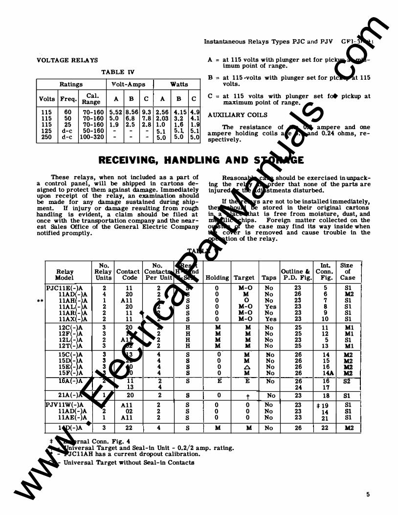
V OLTAGE RELAYS
TABLE IV
Ratings Volt-A mps
V olts Freq. Cal. A B c Range
115 60 70-160 5.52 8.56 9.3 115 50 70-160 5.0 6.8 7.8 115 25 70-160 1.9 2.5 2.8 125 d-e 50-160 - - -250 d-e 100-320 - - -
Watts
A B
2.56 4.15 2.03 3.2 1.0 1.6 5.1 5.1, 5.0 5.0
c
4.9 4.1 1.9 5.1 5.0
Instantaneous Relays Types PJC and PJV CFl<llO�i
A = at 115 volts with plunger set for pickup at mtnimum point of range.
B = at 115 •volts with plunger set for pickup at 115 volts.
C = at 115 volts with plunger set for pickup at maximum point of range.
AUXILIARY COILS
The resistance of the 0.2 ampere and one ampere holding coils are 6.1 and 0.24 ohms, respectively.
RECEIVING, HANDLING AND STORAGE These relays, when not included as a part of
a control panel, will be shipped in cartons designed to protect them against damage. Immediately upon receipt of the relay, an examination should be made for any damage sustained during shipment. If injury or damage resulting from rough handling is evident, a claim should be filed at once with the transportation company and the nearest Sales Office of the General Electric Company notified promptly.
Reasonable care should be exercised in unpacking the relay in order that none of the parts are injured or the adjustments disturbed.
If the relays are not to be installed immediately, they should be stored in their original cartons in a place that is free from moisture, dust, and metallic chips. Foreign matter collected on the outside of the case may find its way inside when the cover is removed and cause trouble in the operation of the relay.
TABLE V
**
No. No. Reset Relay Relay Contact Contacts H-Hand Model Units Code Per Unit S-Self Holding Target
PJC11E(-)A 2 11 2 s 0 11A D -A 4 20 2 s 0
llAH -A 1 All 2 s 0 llAL -A 2 20 2 s 0 llAR -A 2 ll 2 s 0
11AX -A 2 ll 2 s 0 12C�-r 3 20 2 H M 12F -A 3 ll 2 H M 12L(- A 2 All 2 H M 12T(-A 3 02 2 H M l5Crr 3 13 4 s 0 15D -A 3 22 4 s 0 15E -A 3 40 4 s 0 15F -A 3 40 4 s 0 16A(-)A 2 11 2 s E
13 4 21A (-)A 1 20 2 s 0
PJVllW(-)A 1 All 2 s 0 11A D(-�A 2 02 2 s 0
llA E(-A 1 All 2 s 0
14D(-)A 3 22 4 s M
:f: - External Conn. Fig. 4 t - Universal Target and Seal-in Unit - 0.2/2 amp. rating.
** - PJCllAH has a current dropout calibration.
A -Universal Target without Seal-in Contacts
M-0 M 0
M-0 M-0 M-0
M M M M
� . M M A M E
t 0 0 0
M
Int. Size Outline&: Conn. of
Taps P.D. Fig. Fig. Case
No 23 5 S1 No 26 6 M2 No 23 7 S1 Yes 23 8 Sl No 23 9 S1 Yes 23 10 S1
No 25 ll M1 No 25 12 M1 No 23 5 S1 No 25 13 Ml No 26 14 M2 No 26 15 M2 No 26 16 M2 No 26 14A M2 No 26 16 82
24 17 No 23 18 81
No 23 * 19 S1 No 23 14 81 No 23 21 Sl
No 26 22 M2
5 www . El
ectric
alPar
tMan
uals
. com
GEI-31094 Instantaneous Relays Types PJC and PJV
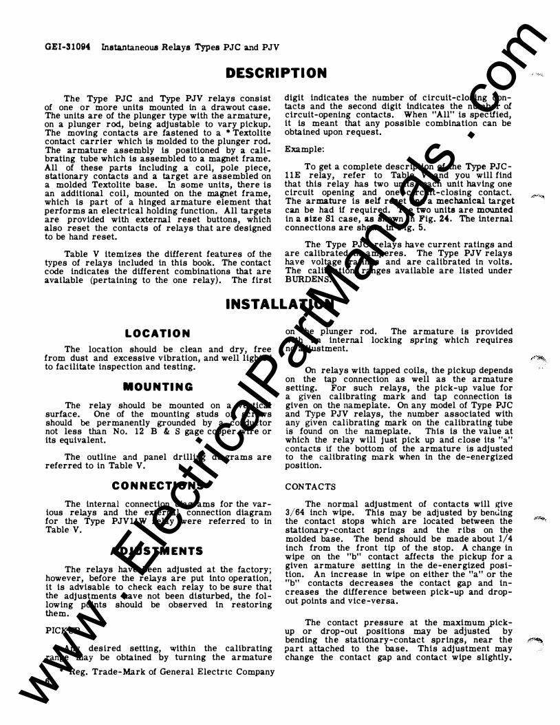
DESCRIPTION The Type PJC and Type PJV relays consist
of one or more units mounted in a drawout case. The units are of the plunger type with the armature, on a plunger rod, being adjustable to vary pickup. The moving contacts are fastened to a * Textolite contact carrier which is molded to the plunger rod. The armature assembly is positioned by a calibrating tube which is assembled to a magnet frame. All of these parts including a coil, pole piece, stationary contacts and a target are assembled on a molded Textolite base. In some units, there is an additional coil, mounted on the magnet frame, which is part of a hinged armature element that performs an electrical holding function. All targets are provided with external reset buttons, which also reset the contacts of relays that are designed to be hand reset.
Table V itemizes the different features of the types of relays included in this book. The contact code indicates the different combinations that are available (pertaining to the one relay). The first
digit indicates the number of circuit-closing contacts and the second digit indicates the number of circuit-opening contacts. When "All" is specified, it is meant that any possible combination can be obtained upon request.
Example:
To get a complete description of the Type PJCllE relay, refer to Table V and you will find that this relay has two units, each unit having one circuit opening and one circuit-closing contact. The armature is self reset and a mechanical target can be had if required. The two units are mounted in a size Sl case, as shown in Fig. 24. The internal connections are shown in Fig. 5.
The Type PJC relays have current ratings and are calibrated in amperes. The Type PJV relays have voltage ratings and are calibrated in volts. The calibration ranges available are listed under BURDENS.
INSTALLATION LOCATION
The location should be clean and dry, free from dust and excessive vibration, and well lighted to facilitate inspection and testing.
MOUNTING
The relay should be mounted on a vertical surface. One of the mounting studs or screws should be permanently grounded by a conductor not less than No. 12 B & S gage copper wire or its equivalent.
The outline and panel drilling diagrams are referred to in Table V.
CONNECTIONS
The internal connection diagrams for the various relays and the external connection diagram for the Type PJVllW relay were referred to in Table V.
ADJUSTMENTS
The relays have been adjusted at the factory; however, before the relays are put into operation, it is advisablt: to check each relay to be sure that the adjustments have not been disturbed, the following points should be observed in restoring them.
PICKUP
Any desired setting, within the calibrating range may be obtained by turning the armature
• Reg. Trade-Mark of General Electrtc Company 6
on the plunger rod. The armature is provided with an internal locking spring which requires no adjustment.
On relays with tapped coils, the pickup depends on the tap connection as well as the armature setting. For such relays, the pick-up value for a given calibrating mark and tap connection is given on the nameplate. On any model of Type PJC and Type PJV relays, the number associated with any given calibrating mark on the calibrating tube is found on the nameplate. This is the value at which the relay will just pick up and close its "a"
contacts if the bottom of the armature is adjusted to the calibrating mark when in the de-energized position.
CONTACTS
The normal adjustment of contacts will give 3/64 inch wipe. This may be adjusted by bem.ling the contact stops which are located between the stationary-contact springs and the ribs on the molded base. The bend should be made about 1/4 inch from the front tip of the stop. A change in wipe on the "b" contact affects the pickup for a given armature setting in the de-energized position. An increase in wipe on either the "a" or the "b" contacts decreases the contact gap and increases the difference between pick-up and dropout points and vice-versa.
The contact pressure at the maximum/ickup or drop-out positions may be adjuste by bending the stationary-contact springs, near the part attached to the base. This adjustment may change the contact gap and contact wipe slightly.
www . El
ectric
alPar
tMan
uals
. com
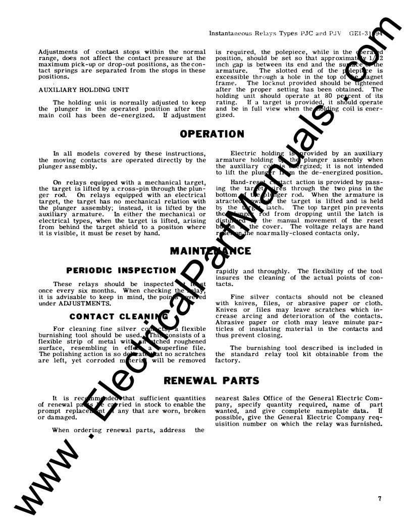
Adjustments of contact stops within the normal range, does not affect the contact pressure at the maximum pick-up or drop-out positions, as the contact springs are separated from the stops in these positions.
AUXILIARY HOLDING UNIT
The holding unit is normally adjusted to keep the plunger in the operated position after the main coil has been de-energized. If adjustment
Instantaneous Relays Types PJC and P.JV GEI-31094
is required, the polepiece, while in the operated position, should be set so that approximately 1/32 inch gap is between its end and the surface of the armature. The slotted end of the polepiece is excessible through a hole in the top of the magnet frame. The locknut provided should be tightened after the proper setting has been obtained. The holding unit should operate at 80 percent of its rating. If a target is provided, it should operate and be in full view when the holding coil is energized.
OPERATION In all models covered by these instructions,
the moving contacts are operated directly by the plunger assembly.
On relays equipped with a mechanical target, the target is lifted by a cross-pin through the plunger rod. On relays equipped with an electrical target, the target has no mechanical relation with the plunger assembly; instead, it is lifted by the auxiliary armature. In either the mechanical or electrical types, when the target is lifted, arising from behind the target shield to a position where it is visible, it must be reset by hand.
Electric holding is provided by an auxiliary armature holding up the plunger assembly when the auxiliary coil is energized; it is not intended to lift the plunger from the de-energized position.
Hand-reset contact action is provided by passing the target wires through the two pins in the bottom of the plunger rod. When the armature is atracted upward, the target is lifted and is held by the target latch. The top target pin prevents the plunger rod from dropping until the latch is disturbed by the manual movement of the reset button in the cover. The voltage relays are hand reset on the noarmally-closed contacts only.
MAINTENANCE PERIODIC INSPECTION
These relays should be inspected at least once every six months. When checking the relay, it is advisable to keep in mind, the points covered under ADJUSTMENTS.
CONTACT CLEANING
For cleaning fine silver contacts, a flexible burnishing tool should be used. This consists of a flexible strip of metal with an etched roughened surface, resembling in effect a superfine file. The polishing action is so delicate that no scratches are left, yet corroded material will be removed
rapidly and throughly. The flexibility of the tool insures the cleaning of the actual points of contacts.
Fine silver contacts should not be cleaned with knives, files, or abrasive paper or cloth. Knives or files may leave scratches which increase arcing and deterioration of the contacts. Abrasive paper or cloth may leave minute particles of insulating material in the contacts and thus prevent closing.
The burnishing tool described is included in the standard relay tool kit obtainable from the factory.
RENEWAL PARTS It is recommended that sufficient quantities
of renewal parts be carried in stock to enable the prompt replacement of any that are worn, broken or damaged.
When ordering renewal parts, address the
nearest Sales Office of the General Electric Company, specify quantity required, name of part wanted, and give complete nameplate data. If possible, give the General Electric Company requisition number on which the relay was furnished.
7 www . El
ectric
alPar
tMan
uals
. com
8
GEI-31094 Instantaneous Relays Type PJC and PJV
llr-
[ -
) ) 1 3 5 7 2 4 6 8
""�,,� CNHE' J5ED) L-
A--c SCX.Jf?CE
ll
) 9 10:
�r-::-1--<>- +
L<>- -
PJVll PJVll D w
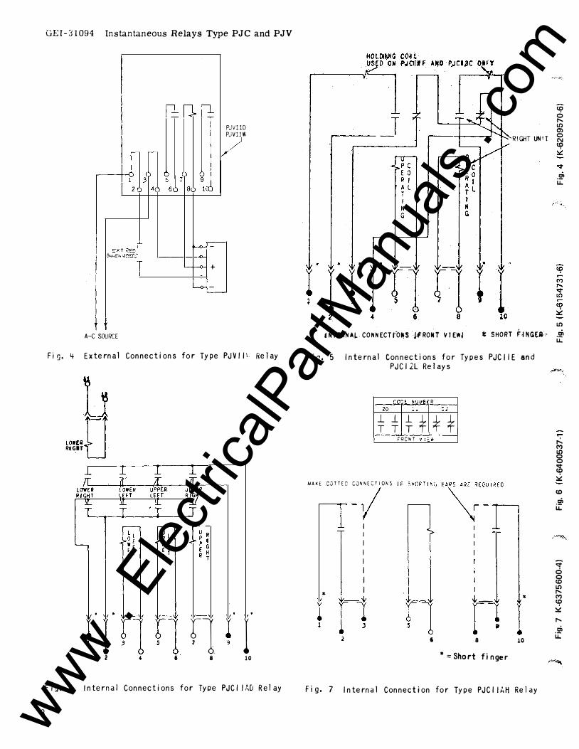
Fi�. 4 External Connections for Type PJVIIL Relay
11 lOW£110 RtiGIT
t I r1 r1 r1 t I 2 6 8 10
F ig. 6 Internal Connections for Type PJCIIA[J Relay
tl? 0 r-. U) m RIGHT lJNIT �
1.0 ::.;:
.5!' u.
U) UT(RNAJ,.. CONNECT(O�S j�RONT VIEW� i: SHORT h NG(Il' .5!'
Fig. 5 Internal Connections for Types PJCJIE and PJCI2L Relays
CC:t NUMB R 20 .. Ct
****** FRCNT VIEw ·----
MAKE COTTED CJNNECT!Q�S �-1 I I I I
I I I I *
{-_ * r1 r1 l fl I ' 8 10
* ==Short finger
Fig. 7 Internal Connection for Type PJCI lkH Relay
u.
... r-. M U) 0 0 Cb � 1.0 .� u.
<r 0 0 1.0 U) r-. M tl? � r-. ti>
u::
,,.,
www . El
ectric
alPar
tMan
uals
. com
co .<!! u.
..... N L.O co L.O 0 M � �
.E' u.
..... en L.O <( N cg M 0 ..... .2' u.
..... . E' u.
• •
LEFT UNH
- R;�GHT UNitT
fll, I r1 r1 fl z ' a· a to
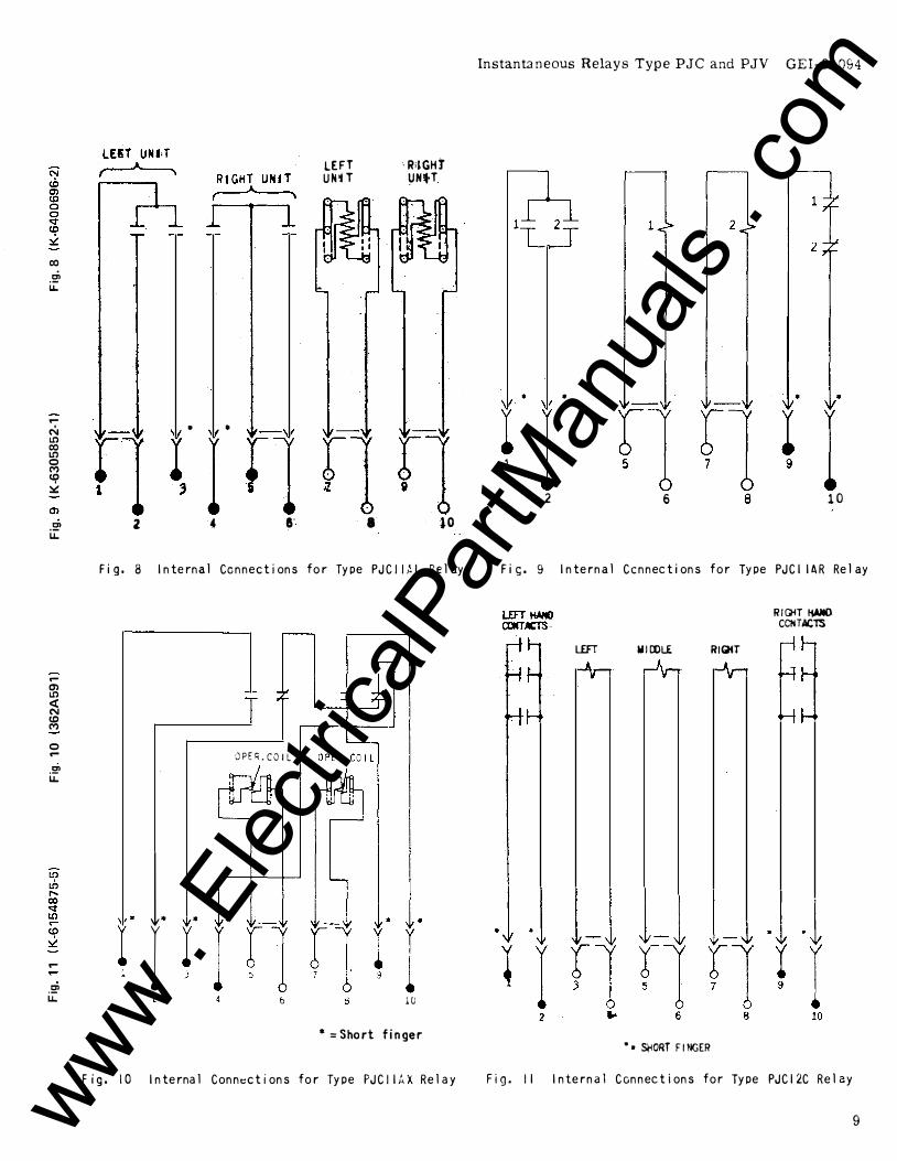
Fig. 8 Internal Connections for Type PJCIIH Relay
r 1. . . I � I
OPEfi.CO I L
6 10
• =Short finger
Fig. 10 Internal Conn�::ctions for Type PJCIIAX Relay
Instantaneous Relays Type PJC and PJV GEI-31094
•
l I 1
2 6 8 10
Fie;;. 9 Internal Connections for Type PJCIIA R Rel ay
LEFT WIOOLE
"• Sl'ORT FINGER
RIGKT
RIGH !tMO CCIHACTS
Fig. II Internal Connections for Type PJCI2C Relay
9 www . El
ectric
alPar
tMan
uals
. com
GEI-31094 Instantaneous Relays Types PJC and PJV
LEFT UN IT TOP (FRONT VfEW)UNJT
tlt 0 5 6
2 4 6
RiGHT UNIT (FRONT VIEW)
I ' � . tlr 7 b 9
8
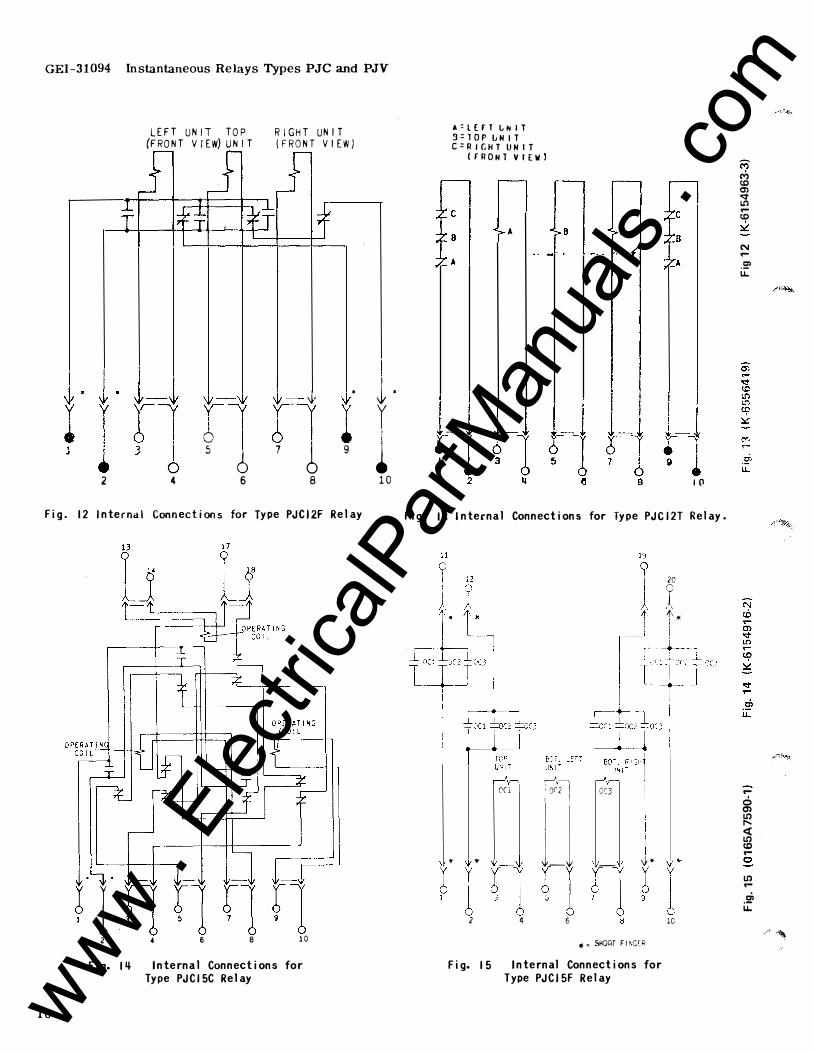
Fig. 12 Internal Connections for Type PJCI2F Relay
10
� I f1 r1 f1 fl 2 4 6 8 10
Fig. 1� Internal Connections for Type PJCI5C Relay
I l . y l 10
A=l(fl LNIT 3=TOP LNIT C=RIGHT UNIT
(fRONT VIEW)
c f
1(1
Fig. 13 Internal Connections for Type PJCI2T Relay.
,-'1[---, �. OCl : or2 I or3
• • _J l_l -I�1�1r1 2 4 6
v*' X • � SHORT F I NGcR
Fig. 15 Internal Connections for Type PJCI5F Relay
20
r ,, 1'*
..
lC
M c<, (.C 0') <::1' l.C) .-(.C � N .-.!:' u.
Cl u.
.-6 0') l.C) r-. � l.C) (.C .-0 l.C) .-.!:' u.
.·' •"'\
www . El
ectric
alPar
tMan
uals
. com
c.o .... .� LL.
.... r.:. c.o 1!'1 co � 0 .... 0
.� LL.
co .... . !:' LL.
Ol ....
. !:' LL.
Fig.
13 0 i 14 I 9 �---;1; I I
I A �A -� :� I ! s
:t B .-J, r--4 c
c ·--l�
RELAY A • TOP UNIT ReLAY B• LOWER LEFT UNIT RELAY C• LOWER RIGHT UNIT
{ll' v • 5
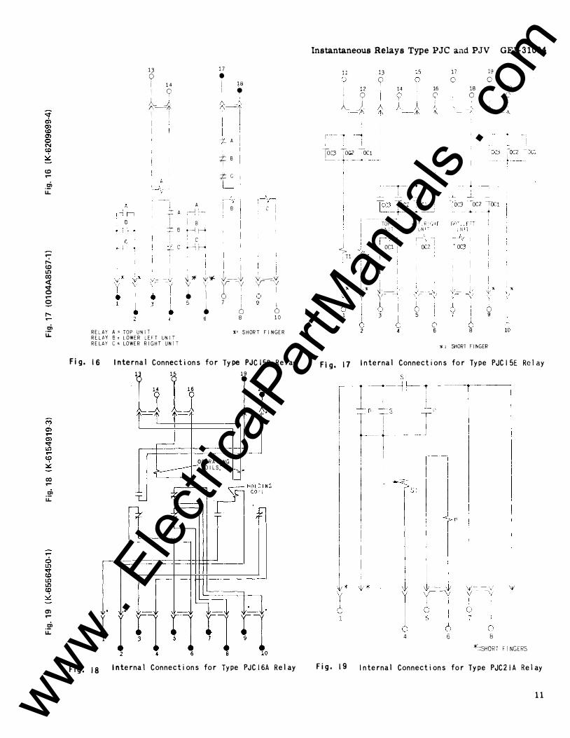
16 Internal Connections
I H
15
lJ L� -
�� y i �
for
17 • i 18 I • ;\_J "'-1
! A I
:;ts I � C I L__j
i B
i �-t ['Y 7 !
I C) 8
c i
�'-� yV 6 !, I 6 10
X• SHORT FINGER
Type PJCI5D Relay
19
I '" . r.
OPERATING COILS.
Fig. 18 Internal Connections for Type PJCI6A Relay
Instantaneous Relays Type PJC and PJV GEI-31094 11 0
12 ' 9 lJ. -A
, --- ,
I --'-
fOC3 jOG.2 -OC1 �
-� ---
� ,Tl
"- " I �,1; y y
6 I
I 1 6 2
13 9
---r--_L
TOP tk,T. � Uh ,' T L N
16 0 j ·I\
,- ,
-,
OC1 i , QC2 ,
I
I �' --------=-- � ,·- __ , y- \
-- \
6 I 0 3 5
0 6
17 0
l 18 0
19 0
J . OC3 - �()cz Toc1
-- � -i
• OC3
). �--I
6 9
6 8 ;c ' SHORT FINGER
20 \:'
. ,. , .
�-
lb
Fig. 17 Internal Connections for Type PJCI 5E Relay
4 6 8 *=SHORT FINGERS
Fig. 19 Internal Connections for Type PJC21A Relay
11 www . El
ectric
alPar
tMan
uals
. com
GJ.�I-31094 lnstantaneous Relays Type PJC and PJV
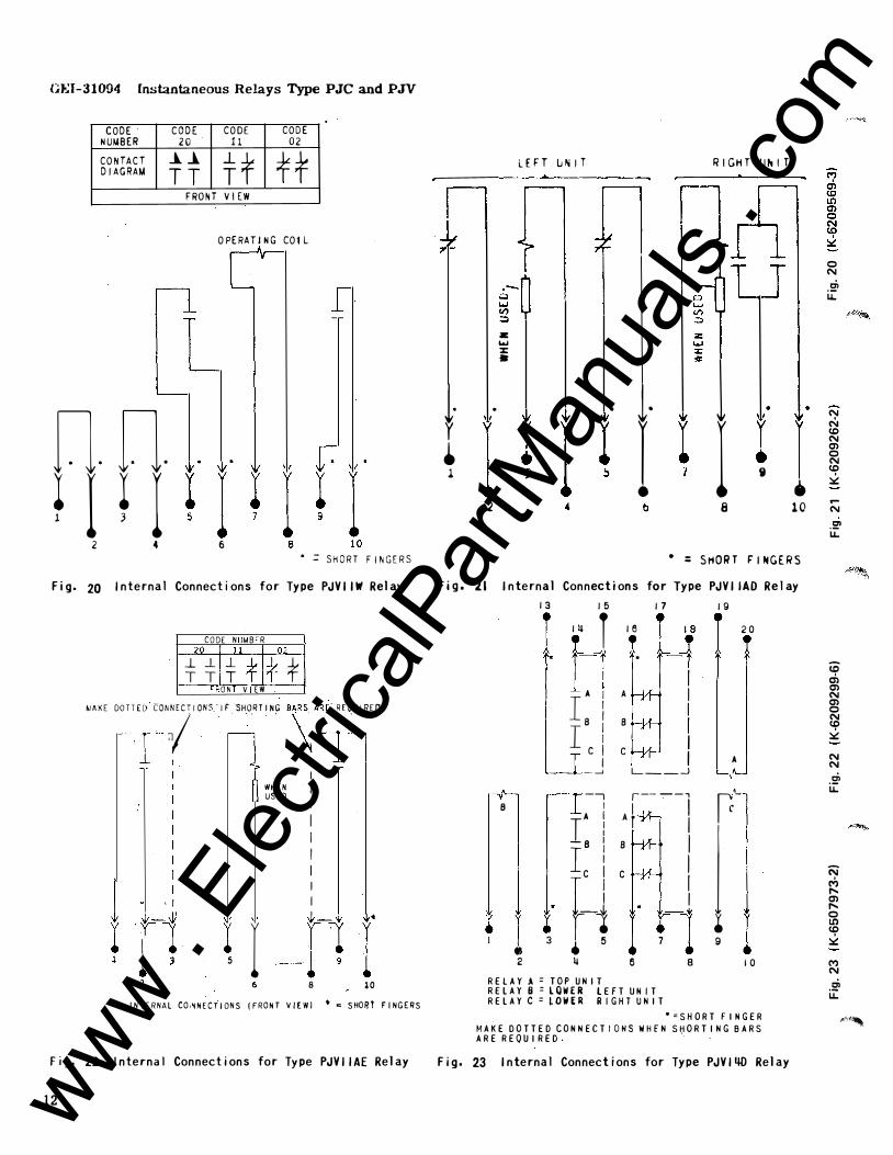
CODE CODE CODE CODE NUfJBER 20 11 02 CONTACT ..L..l tf ff DIAGRAM TT
FRONT VIEW
OPERATJ NG COtl
n. n. .
� I � I � I 1 2 4 6
• =SHORT FINGERS
Fig. 20 Internal Connections for Type PJVIIW Relay
CODE N MB R 20 11 0�
j_j_ * *'* * TT ON V EW
"" oo m" ''",7 ""' " '"""""' "f "\'�' "'QO "'"·
I
'I
r 5
I
�m I I I I I I I I
r --r1 r 8 10
INTERNAL CO.�NECTIONS !fRONT VIEWJ • � SHORt FINGERS
Fig. 22 Internal Connections for Type PJVIIAE Relay
12
LEFT u"'IT RIGHT UhiT
n
l· r • l
z: '"" ::z:: •
. . l· �
I � I � I t I 2 8
r i I •
10
• : SHORT FiNGERS
Fig. 21 Internal Connections for Type PJVIIAD Re lay
13 I 5 17 19
I �� r 16 L4 I 20
t-"1 ! T . I
A I A I IB I I B I I c i I c I I I A _ _J L __ _j
r� ---, ,----, B I A } I TA !
j -s I B I
i Ic i c I
f� I I . l • l f-1 I 3 • 5 9 • 2 � 6 8 10
RELAY A= TOP UNIT RELAY 8 =LOWER lEFT UNIT RELAY C =LOWER RIGHT UNIT
• =SHORT fINGER MAKE DOTTED CONNECT I OHS WHEN S�ORT I NG BARS ARE REQUIRED.
Fig . 23 Internal Connections for Type PJVI40 Relay
•
0 N .� u..
N N co N en 0 N co � .... N .!2' u..
tO a, en N en 0 N co � N N .� u..
'N M " en " 0 U') co � M N .!2' u..
"''"'
www . El
ectric
alPar
tMan
uals
. com
.2' u.
Instantaneous Relays Type PJC and PJV GEI-31094
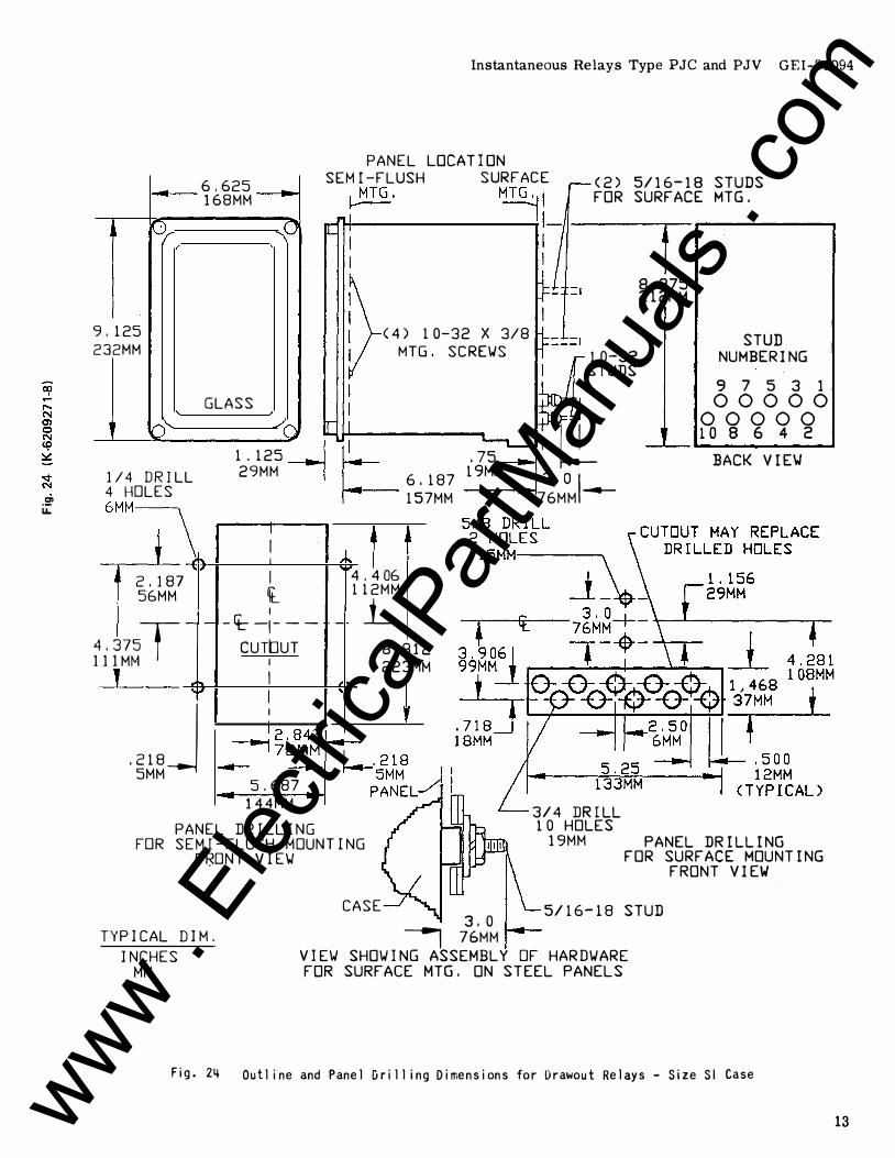
- 6. 625 168MM
PANEL LOCATION
SEM I -FLUSH SURFACE <2> 5/16-18 STUDS FOR SURFACE MTG.
IO.r .,p �MTG . MTGl l
H---------..: :-1------.f-.-------....
9' 125 232MM
< 4) 1 0- 32 X 3/ 8
MTG. SCREWS 10-32 STUDS
8.375 212MM
STUD
NUMBERING
GLASS 9 7 5 3 1
00000 b"
1/4 DRILL 4 HOLES 6MM�
2' 187 56MM
4.375T 111 Mt--1
J
- -
lo'
. 218J 5MM
/a 1 . 12s - _ I 29MM I
I I I
I t I -ct- -�---
CUTbUT I
I I
I
I
5.687 144MM
I I u_ � 6. 187 iJ�M :13. 0 I 1--- 157MM 176MM ---
4.406 112MM
- _L 8. 81
223M 2 M
--I.-00000 10 8 6 4 2
BACK VIEW
FOR PANEL DRILLING SEtv1I-FLUSH MOUNTING
F�ONT VIEW
3/4 DRILL 10 HOLES
19MM PANEL DRILLING FOR SURFACE MOUNTING
FRONT VIEW
TYPICAL DIM.
INCHES tv1tv1
Fig. 24
CASE 3.0 I 76MM
5/16-18 STUD
VIEW SHOWING ASSEtvlBLY OF HARDWARE FOR SURFACE tv1TG. ON STEEL PANELS
Outline and Panel [irilling Dimensions for l)rawout Relays - Size Sl Case
13 www . El
ectric
alPar
tMan
uals
. com

GEI-31094 Instantaneous Relays Type PJC and PJV
6.625 168MM
0/
0.312 261MM
GLASS
lr<'--
,p
/a
PANEL LOCATION SEMI-FLUSH SURFACE
�MTG. MTG
..:.jl
(4) 1 0-32 X 3/8
MTG. SCREW'S
,-
(2) 5/16-18 STUDS FOR SURFACE MTG.
1 9171 51311
00000 00000
9.875 201 81614 12
25 0MM
---I.-
STUD NUMBERING
9 7 5 3 1 00000
00000 10 8 6 4· 2
BACK V I E'W 1/4 DRILL 4 HOLES
1 . 125-
_ I 29MM I
CUTOUTS MAY REPLACE �
14
6MM� 2.781 56MM
5.562T 141MM
- -
' r...
. 218 I SMM ---1
I I
I [_ I
-� - � ---
CUTbUT I
I I I I
5.687 144MM
PANEL DRILLING
5 1
-.000
27MM
j_ 10.000
254MM
u FOR SEMI-FLUSH MOUNTING
FRONT VIE\.J
TYPICAL DIM.
CA
3.0 I 76MM
5.25
DRILLED HOLES
1. 75 [ 46MM
4.875 123MM
t
133MM
3/4 DRILL 20 HOLES
19MM PANEL DR I LL I NG FOR SURFACE MOUNT I NG
FRONT VIEW'
5/16-18 STUD
INCHES MM
VIE\.J SHOWING ASSEMBLY OF HARDWARE FOR SURFACE MTG. ON STEEL PANELS
F11�. 2b Out I ine and Panel Dri II ing Dimensions for Drawout Relays - Size S2 Case
.ri! u.
www . El
ectric
alPar
tMan
uals
. com
(t) N -� u..
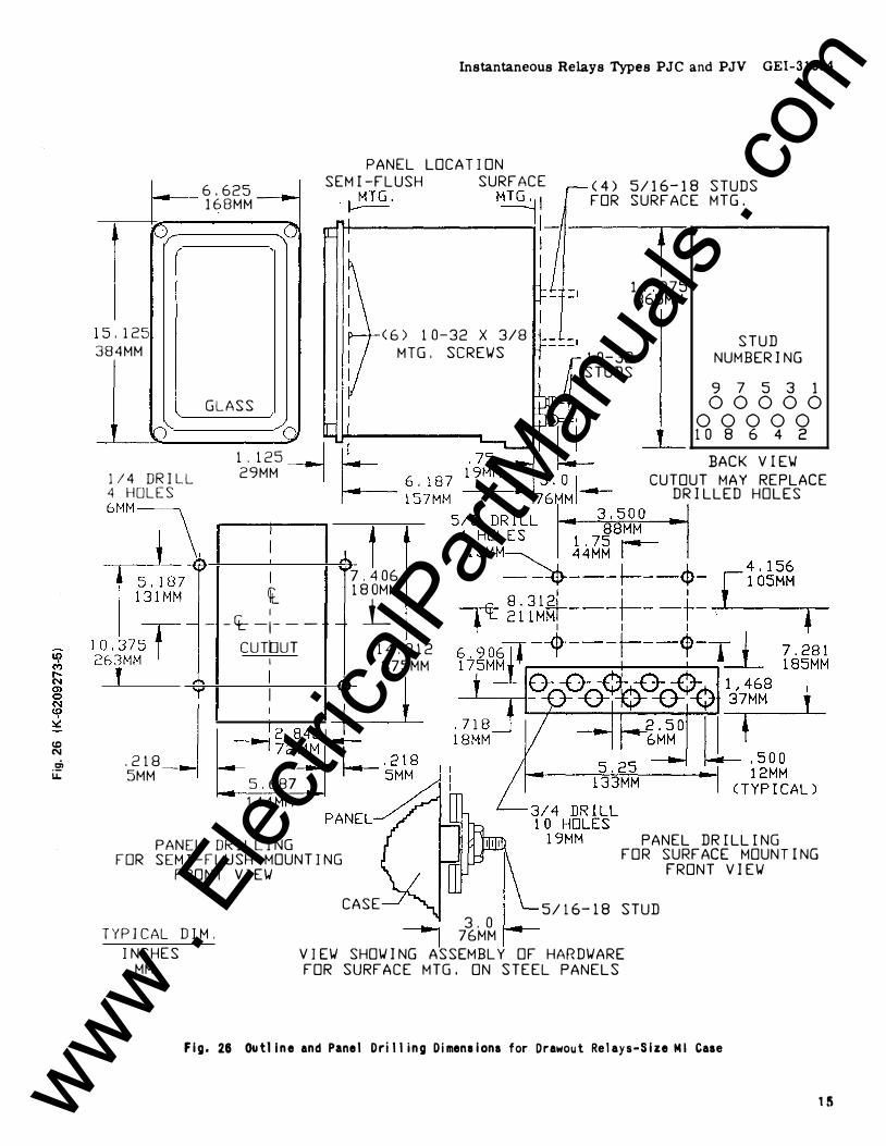
5' 125 384MM
lJ) 1/4 DRILL 4 HOLES 6MM1_\ 0. 187
I _31MM
10' 37;r-263MM
) T '
-
.2l8 I 5MM --1
6.625 __ .,... 168MM
,o
GLASS
( 1 . 125 - _ I 29MM I
I I I l I
- -rt:- -�---CUTbUT
I
I I I
I
5.687 144MM
PANEL DRILLING
Instantaneous Relays Types PJC and PJV GEI-31094
PANEL LOCATION SEMI-FLUSH SURFACE (4) 5/16-18 STUDS
FOR SURFACE MTG . . �TG. MTGl l
H----------i :-1----.. f---------.
7 1
-
< 6) 1 0-32 X 3/8 MTG. SCREWS
.406 80MM _L
14.812 375MM
w
14.375 365MM
10-32 STUDS
STUD NUMBERING
9 7 5 3 1 00000
00000 10 8 6 4 2
BACK VIEW CUTOUT MAY REPLACE
DRILLED HOLES
PANEL DR I LL I NG FOR SEMI-FLUSH MOUNTING
FRONT VIEW
FOR SURFACE MOUNTING FRONT VIEW
TYPICAL DIM. INCHES
MM
CASE � 3.0
I 76MM 5/16-18 STUD
VIEW SHOWING ASSEMBLY OF HARDWARE FOR SURFACE MTG. ON STEEL PANELS
Fig. 28 Outl lne and Panel Drilling Dimensions for Drawout Relays-Size Ml Case
15 www . El
ectric
alPar
tMan
uals
. com
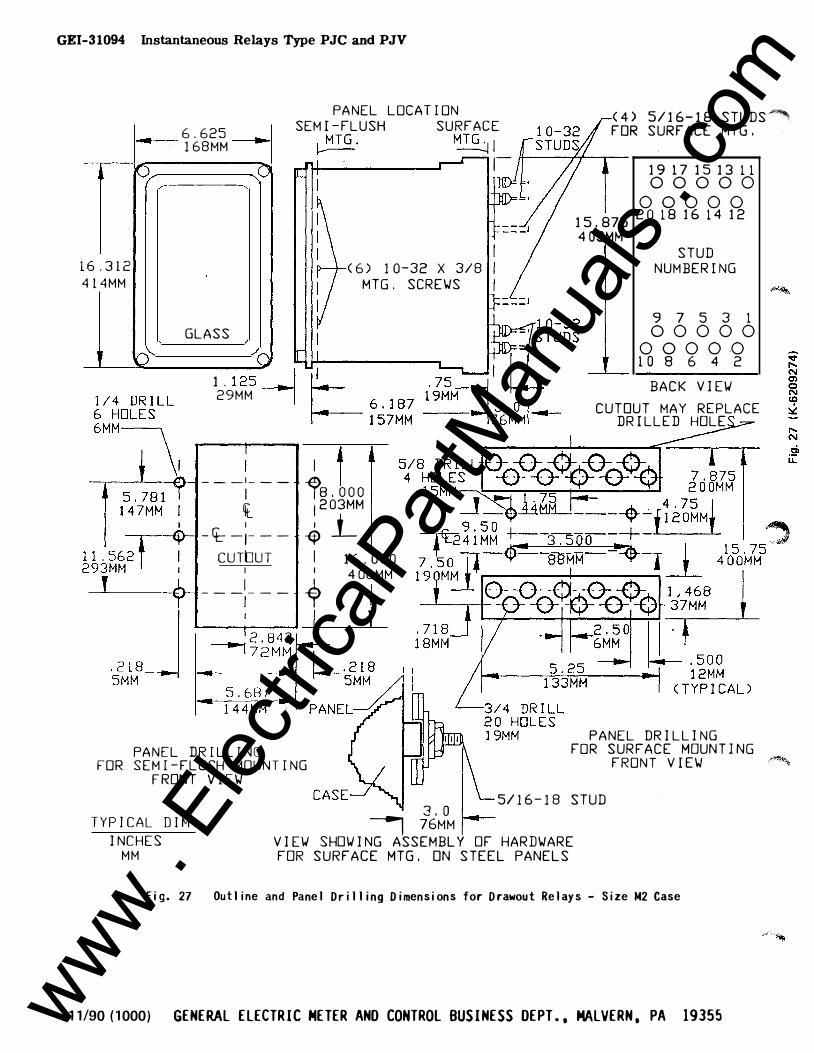
GEI-31094 Instantaneous Relays Type PJC and PJV
PANEL LOCATION
6.625 SEMI-FLUSH SURFACE
168MM �MTG. MTG
..:.j I 10/
6.312 414MM
0
1 1 .56;r-293MM
2 T J
� -----
GLASS
/0 1 . 125
-_ I
29MM I
(6) 10-32 X 3/8 MTG. SCREWS
I - -
- ;--- l>s.ooo l I
203MM
-fi- - 1- - - 4 j_ CUTbUT I 16.000
___ ; __
_ � 406MM
L--+--------11 w PANEL DRILLING
FOR SEMI-FLUSH MOUNTING FRONT VIEW
,-
< 4) 5/16-18 STUDs"'"'
FOR SURFACE MTG.
1917151311 00000
00000 15.875
2018161412
403MM STUD
NUMBER I NG
9 7 5 3 1 00000
0000 .0 10 8 6 4 2
BACK VIEW
CUTOUT MAY REPLACE DRILLED HOLE
PANEL DRILLING FOR SURFACE MOUNTING
FRONT VIEW
5/16-18 STUD 3.0 TYPICAL DIM. I 76MM
INCHES VIEW SHOWING ASSEMBLY OF HARDWARE MM FOR SURFACE MTG. ON STEEL PANELS
Fig. 27 Outline and Panel Drilling Dimensions for Drawout Relays - Size M2 Case
11/90 (1000) GENERAL ELECTRIC METER AND CONTROL BUSINESS DEPT., MALVERN, PA 19355 www . El
ectric
alPar
tMan
uals
. com
Recommended