Design Guide: TIDA-050047Integrated USB Type-C PD and Charging ReferenceDesign for 2-4 Cell Batteries
DescriptionThe Integrated USB Type-C® PD and ChargingReference Design for 2-4 Cell Batteries is a 2 in 1,USB Type-C and PD controller along with a batterycharging system. This reference design can supportcharging 2S to 4S batteries through a USB Type-Cport, in addition to the standard Type-Ccommunication, Power Delivery negotiations, powerrole swaps, and data role swaps. This board featurescharging up to 20 V at 5 A, without the need for anyexternal FETs enabling a much smaller design size,reducing total BOM cost, and so on. In addition, anexternal microprocessor is not necessary as the USB-PD Controller can handle the I2C communication tothe battery charger IC. As a result, there is no needfor any Firmware development work and the designgreatly reduces the total time needed to market.
ResourcesTIDA-050047 Design FolderTPS25750, BQ25792 Product FolderTPS54531, TLV755P Product FolderTVS2200 Product Folder
Ask our TI E2E™ support experts
Features• Configurable as Source-Sink or Sink-Only power
roles• Configuration Options Selected through Binary
Vending Machine GUI• Comprehensive Power Path Management and
Protection• Supports Charging of a 2S-4S Battery• Seamless Transition Among Buck, Buck-boost and
Boost Functionality• OTG Mode Support in Source Mode
Applications• Battery Pack: Cordless Power Tool• Retail Automation and Payment• Wirless Speakers• Headsets, Headphones, and Earbuds• Portable Electronics• Industrial Applications
www.ti.com Description
TIDUEY1 – NOVEMBER 2020Submit Document Feedback
Integrated USB Type-C PD and Charging Reference Design for 2-4 CellBatteries
1
Copyright © 2020 Texas Instruments Incorporated

1 System DescriptionThe Integrated USB Type-C PD and Charging reference design is a USB Type-C and PD controller system alongwith a battery charging system capable of 100W sinking and up to 45W sourcing. This reference design cansupport charging 2s to 4s batteries via a USB Type-C port, in addition to Type-C communication and PowerDelivery negotiations.
This board features charging up to 20 V at 5 A, without the need for any external FETs. Furthermore, an externalmicroprocessor is also not necessary as the USB-PD Controller will handle the I2C communications to thebattery charger IC to configure the appropriate functionality. Some examples include setting the chargingvoltage, charging current and configuring it for OTG Mode.
1.1 Key System SpecificationsTable 1-1. Key System Specifications
PARAMETER SPECIFICATIONS DETAILSSink Capabilities 5 V - 20 V VBUS from Type-C Input
Source Capabilities 5 V - 20 V Output from BQ25792
Cell Configurations 2 cell - 4 cell Battery Cell Number
Charge Current Up to 5A Battery Charging Current
OTG Capability Up to 45W Sourcing Power From Battery
System Description www.ti.com
2 Integrated USB Type-C PD and Charging Reference Design for 2-4 CellBatteries
TIDUEY1 – NOVEMBER 2020Submit Document Feedback
Copyright © 2020 Texas Instruments Incorporated
2 System Overview
2.1 Block Diagram
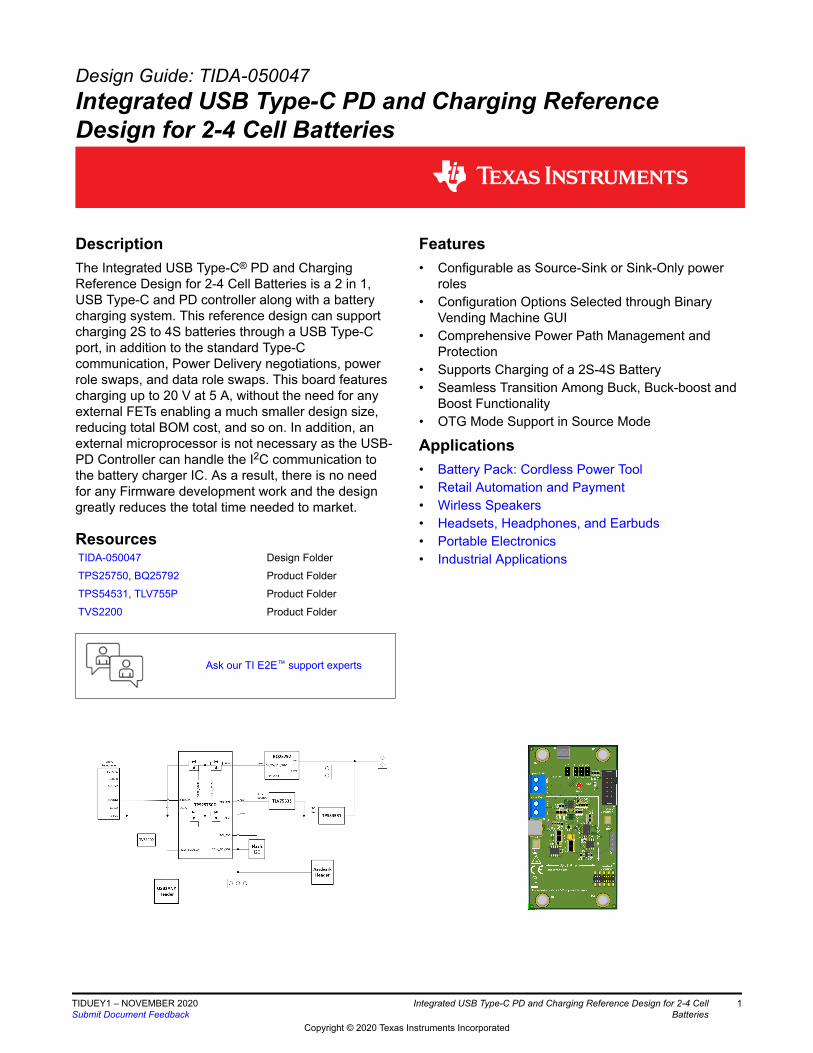
Figure 2-1. TIDA-050047 Block Diagram
2.2 Design ConsiderationsTIDA-050047 shows an example of how to implement a USB Type-C PD system alongside a switching batterycharger that is capable of handling high power and current. This design can be used in power tools, powerbanks, and any various other personal electronic systems. This design could assist different functions from theability to charge a battery, as well as, providing power to the system or switching to OTG mode to source powerto the connected device all through the Type-C connector.
2.3 Highlighted ProductsTPS25750D
The TPS25750D is a stand-alone USB Type-C and Power Delivery (PD) controller providing cable plug andorientation detection for a single USB Type-C connector. Upon cable detection, the TPS25750D communicateson the CC wire using the USB PD protocol. When cable detection and USB PD negotiation are complete, theTPS25750D enables the appropriate power path for sourcing or sinking power depending on the contractnegotiation and configuration.
www.ti.com System Overview
TIDUEY1 – NOVEMBER 2020Submit Document Feedback
Integrated USB Type-C PD and Charging Reference Design for 2-4 CellBatteries
3
Copyright © 2020 Texas Instruments Incorporated
TPS25750D
5 A
LDO
Type-c rp/rd & state
machine, VCONN switches,
USB P D policy engine,
protocol and physical
layer
I2C
Primary
8 GPIO
BQ
Battery
Change
5-20 V
3.3 V
5 V
3.3 V USB
Type-C
Connector
VBUS
CC
VCONN
GND
CC1/2
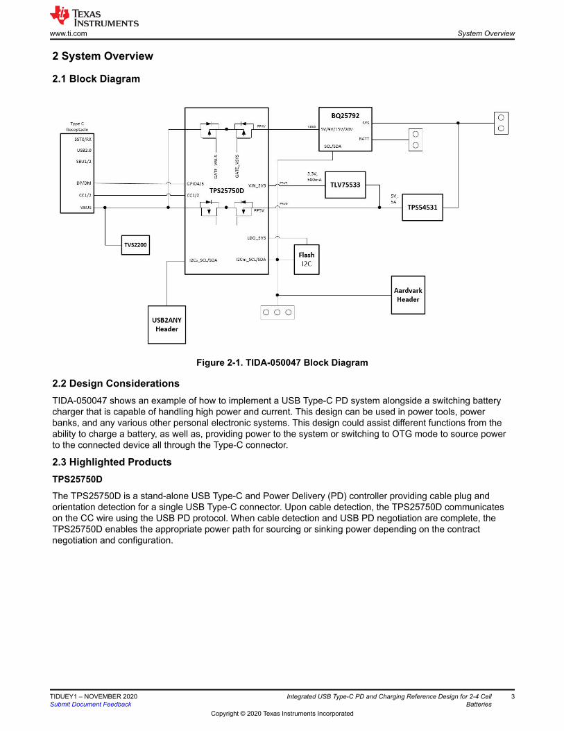
Figure 2-2. TPS25750D Typical Application Circuit
BQ25792
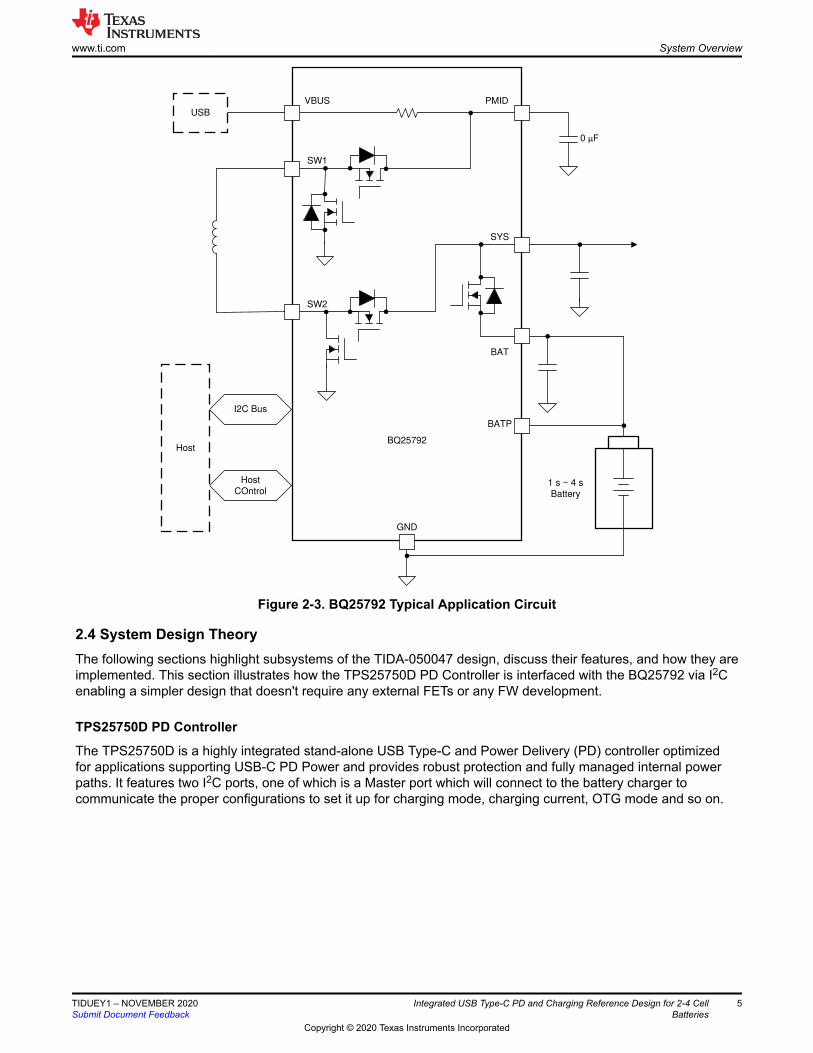
The BQ25792 is an integrated switched-mode buck-boost battery charge management device intended for 1- to4-series cell Li-ion and Li-polymer batteries. The charger features a narrow VDC architecture (NVDC) whichallows the system to be regulated to a minimum value even if the battery is completely discharged. Additionally,the BQ25792 supports input source detection through D+ and D- which is compatible with USB2.0, USB3.0power delivery, non-standard adapters, and high voltage adapters. With dual input source selection, USB OTGsupport, and an integrated 16-bit multi-channel analog-to-digital converter (ADC), the BQ25790 is a completecharging solution.
System Overview www.ti.com
4 Integrated USB Type-C PD and Charging Reference Design for 2-4 CellBatteries
TIDUEY1 – NOVEMBER 2020Submit Document Feedback
Copyright © 2020 Texas Instruments Incorporated
0 �F
USB
VBUS PMID
SW1
SW2
SYS
BAT
BATP
I2C Bus
Host
COntrol
Host
GND
BQ25792
1 s ~ 4 s
Battery
Figure 2-3. BQ25792 Typical Application Circuit
2.4 System Design TheoryThe following sections highlight subsystems of the TIDA-050047 design, discuss their features, and how they areimplemented. This section illustrates how the TPS25750D PD Controller is interfaced with the BQ25792 via I2Cenabling a simpler design that doesn't require any external FETs or any FW development.
TPS25750D PD Controller
The TPS25750D is a highly integrated stand-alone USB Type-C and Power Delivery (PD) controller optimizedfor applications supporting USB-C PD Power and provides robust protection and fully managed internal powerpaths. It features two I2C ports, one of which is a Master port which will connect to the battery charger tocommunicate the proper configurations to set it up for charging mode, charging current, OTG mode and so on.
www.ti.com System Overview
TIDUEY1 – NOVEMBER 2020Submit Document Feedback
Integrated USB Type-C PD and Charging Reference Design for 2-4 CellBatteries
5
Copyright © 2020 Texas Instruments Incorporated
35V0.1uF
C43
10.0kR31
10.0kR32
10.0kR30
GND
GND
10.0kR28
GND
10V10uF
C36
2.20kR25
10V10uF
C37
GND
GND
10V10uF
C35
P3V3
2.20kR24 GND
GND
I2C1_SCL
I2C1_SDA
C_CC1
C_CC2
PPHV
LDO_3V3
LDO_1V5
VBUS
PP5V
LDO_3V3
I2C_SCL
I2C_SDA
PP5V
LDO_3V3LDO_3V3
PP5V
330pF
C41
330pFC42
22uF
C38
0.1uF
C40
22uF
C39GND
1 2
3 4
5 6
7 8
9 10
J5
TSM-105-01-L-DV-P
0R260R27
0R29
I2C_SCL
I2C_SDA
GND
Aardvark Header
P3V3
LDO_1V5
LDO_1V5
C_USB_P
C_USB_N
GND
LDO_3V3
For Internal Debug
4
1
2
3
J7
PEC04SAANGND
I2C_SCLA0
1
A12
A23
VSS4 SDA 5
SCL 6
WP7
VCC8
U5
CAT24C256WI-G
I2C_SDA
LDO_3V31
VIN_3V338
ADCIN12
ADCIN23
GPIO05
GPIO16
GPIO27
GPIO319
GPIO4(USB_P)26
GPIO5(USB_N)27
GPIO637
GPIO736
GPIO1113
I2Cs_SCL9
I2Cs_SDA8
DRAIN15
DRAIN30
I2Cm_IRQ18
I2Cm_SCL17
I2Cm_SDA16
I2Cs_IRQ10
LDO_1V54
PP5V34
PPHV20
VBUS32
VBUS_IN23
CC128
CC229
DRAIN_PAD40
GND11
GND12
GND14
GND31
GND_PAD39
VBUS33
VBUS_IN24
VBUS_IN25
PP5V35
PPHV21
PPHV22
TPS25750DRJK
U4
I2C_SCL
I2C_SDA
GND
GND
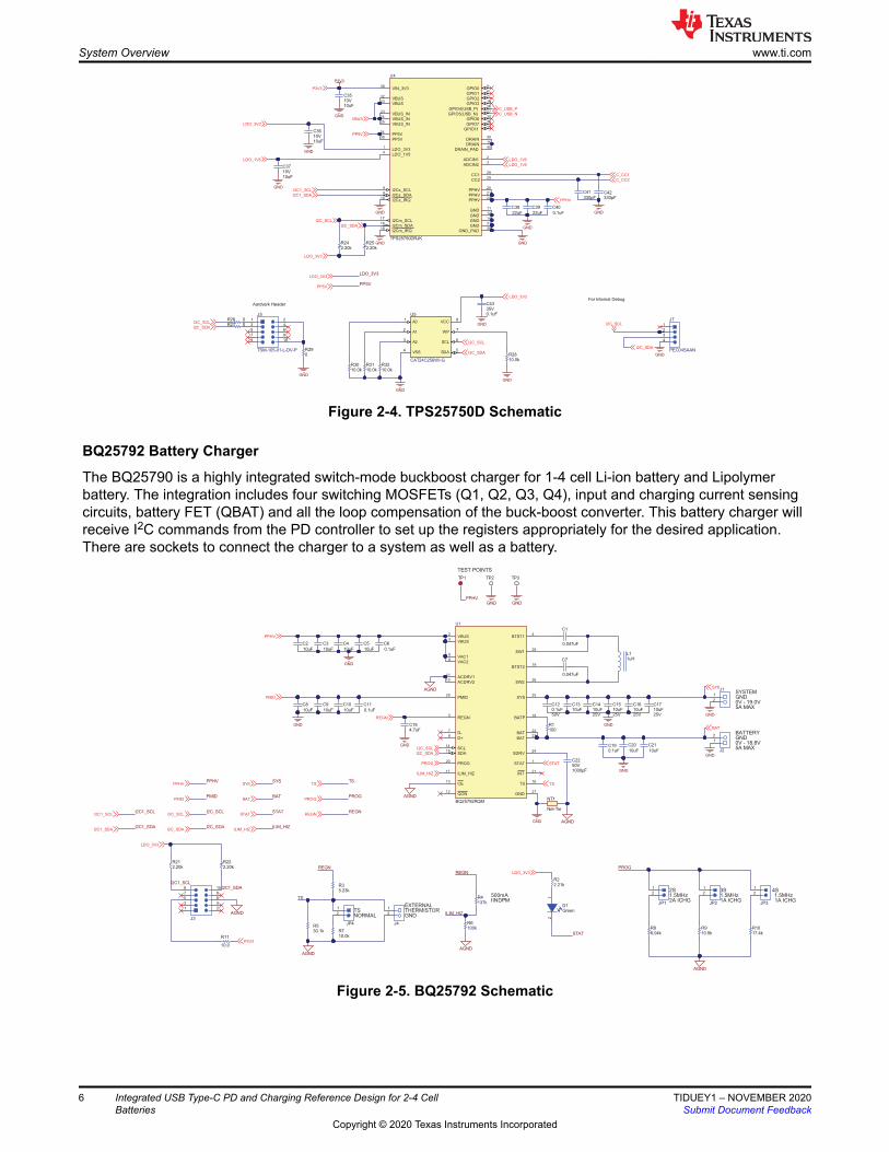
Figure 2-4. TPS25750D Schematic
BQ25792 Battery Charger
The BQ25790 is a highly integrated switch-mode buckboost charger for 1-4 cell Li-ion battery and Lipolymerbattery. The integration includes four switching MOSFETs (Q1, Q2, Q3, Q4), input and charging current sensingcircuits, battery FET (QBAT) and all the loop compensation of the buck-boost converter. This battery charger willreceive I2C commands from the PD controller to set up the registers appropriately for the desired application.There are sockets to connect the charger to a system as well as a battery.
VBUS2
VBUS3
BTST14
BTST219
VAC19
VAC28
ACDRV111
ACDRV210
BAT22
BAT23
SW128
SW226
CE13
INT21
QON12
BATP18
D+6
D-7
ILIM_HIZ17
PMID29
PROG20
REGN5
SCL14
SDA15
SDRV24
STAT1
SYS25
TS16
GND27
BQ25792RQM
U1
1
2
J1
10uF
C21
10uF
C20
10uF
C4
10uF
C5
GND
GND
0.1uF50V
C1210uFC13
10uF25V
C1410uF25V
C1510uF25V
C1610uF25V
C17
GND
GND
0.047uF
C1
0.047uF
C7
4.7uFC18
GND
GND
10uF
C8
10uF
C9
10uF
C10
0.1uF
C11
GND
TS
STAT
ILIM_HIZ
I2C_SCL
I2C_SDA
GND
PPHV
SYS
BAT
SYS
BAT
SYS
BAT
REGN
50V1000pF
C22
STATSTAT
10uF
C3
10uF
C2
ILIM_HIZILIM_HIZ
AGND
100kR6
500mAIINDPM
EXTERNALTHERMISTORGND
1
2
JP1
2S1.5MHz2A ICHG
1
2
JP3
1
2
JP2
3S 4S1.5MHz 1.5MHz1A ICHG 1A ICHG
AGND
PROG
100R1
AGND
ILIM_HIZ
REGN
30.1kR5
NORMAL
5.23kR3
TS
10.0kR7
1
2
JP4
AGND
REGN
TS
TS
PROG
REGNREGN
TS
PROG
PROG
AGND
NT1
Net-Tie
0.1uFC19
PMID
6.04kR8
10.5kR9
17.4kR10
Green
12
D1
2.21kR2
STAT
0.1uF
C6
AGND
TEST POINTS
TP1 TP2 TP3
GND GNDPPHV
GND0V - 19.0V5A MAX
GNDBATTERY
0V - 18.8V5A MAX
SYSTEM
PMIDPMID
PPHVPPHV
I2C_SCL
I2C_SDA
I2C_SCL
I2C_SDA
AGND
10.0
R11
1 2
3 4
5 6
7 8
9 10
J3
I2C1_SDA
P3V3
LDO_3V3
137kR4
1
2
J2
1
2
J4
1uHL1
I2C1_SCL
I2C1_SDA
I2C1_SCL
I2C1_SDA
LDO_3V3
I2C1_SCL
2.20kR21
2.20kR22
Figure 2-5. BQ25792 Schematic
System Overview www.ti.com
6 Integrated USB Type-C PD and Charging Reference Design for 2-4 CellBatteries
TIDUEY1 – NOVEMBER 2020Submit Document Feedback
Copyright © 2020 Texas Instruments Incorporated
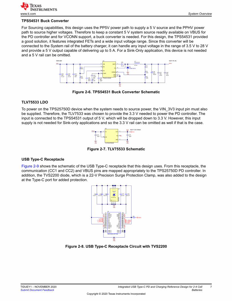
TPS54531 Buck Converter
For Sourcing capabilities, this design uses the PP5V power path to supply a 5 V source and the PPHV powerpath to source higher voltages. Therefore to keep a constant 5 V system source readily available on VBUS forthe PD controller and for VCONN support, a buck converter is needed. For this design, the TPS54531 provideda good solution, it features integrated FETs and a wide input voltage range. Since this converter will beconnected to the System rail of the battery charger, it can handle any input voltage in the range of 3.5 V to 28 Vand provide a 5 V output capable of delivering up to 5 A. For a Sink-Only application, this device is not neededand a 5 V rail can be omitted.
Figure 2-6. TPS54531 Buck Converter Schematic
TLV75533 LDO
To power on the TPS25750D device when the system needs to source power, the VIN_3V3 input pin must alsobe supplied. Therefore, the TLV7533 was chosen to provide the 3.3 V needed to power the PD controller. Theinput is connected to the TPS54531 output of 5 V, which will be dropped down to 3.3 V. However, this inputsupply is not needed for Sink-only applications and so the 3.3 V rail can be omitted as well if that is the case.
Figure 2-7. TLV75533 Schematic
USB Type-C Receptacle
Figure 2-9 shows the schematic of the USB Type-C receptacle that this design uses. From this receptacle, thecommunication (CC1 and CC2) and VBUS pins are mapped appropriately to the TPS25750D PD controller. Inaddition, the TVS2200 diode, which is a 22-V Precision Surge Protection Clamp, was also added to the designat the Type-C port for added protection.
,1,1
*1'
*1'
,1*1
'
3$
'
79
6'5
95
Figure 2-8. USB Type-C Receptacle Circuit with TVS2200
www.ti.com System Overview
TIDUEY1 – NOVEMBER 2020Submit Document Feedback
Integrated USB Type-C PD and Charging Reference Design for 2-4 CellBatteries
7
Copyright © 2020 Texas Instruments Incorporated
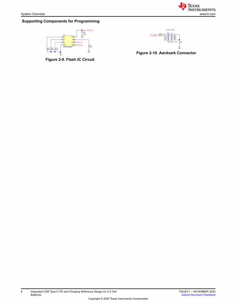
Supporting Components for Programming
Figure 2-9. Flash IC Circuit
1 2
3 4
5 6
7 8
9 10
J5
TSM-105-01-L-DV-P
0R260R27
0R29
I2C_SCL
I2C_SDA
GND
Aardvark Header
Figure 2-10. Aardvark Connector
System Overview www.ti.com
8 Integrated USB Type-C PD and Charging Reference Design for 2-4 CellBatteries
TIDUEY1 – NOVEMBER 2020Submit Document Feedback
Copyright © 2020 Texas Instruments Incorporated

3 Hardware, Software, Testing Requirements, and Test Results
3.1 Hardware and Software RequirementsTo fully test the TIDA-050047, the following components are required:
1. Windows PC running the web-based TPS25750 Application Customization Tool GUI2. The TIDA-050047 board3. Bi-Directional Power Supply for Battery Connection Testing4. High Current Type-C Cable5. E-load or Resistive Load for System Connection Testing
3.2 Application Customization Tool
Configuration Process
Figure 3-1. TPS25750 Application Selection
First, the configuration needs to be selected depending on the application. For this reference design, we need tochoose the first option, it is selected by default as shown in Figure 3-1.
www.ti.com Hardware, Software, Testing Requirements, and Test Results
TIDUEY1 – NOVEMBER 2020Submit Document Feedback
Integrated USB Type-C PD and Charging Reference Design for 2-4 CellBatteries
9
Copyright © 2020 Texas Instruments Incorporated
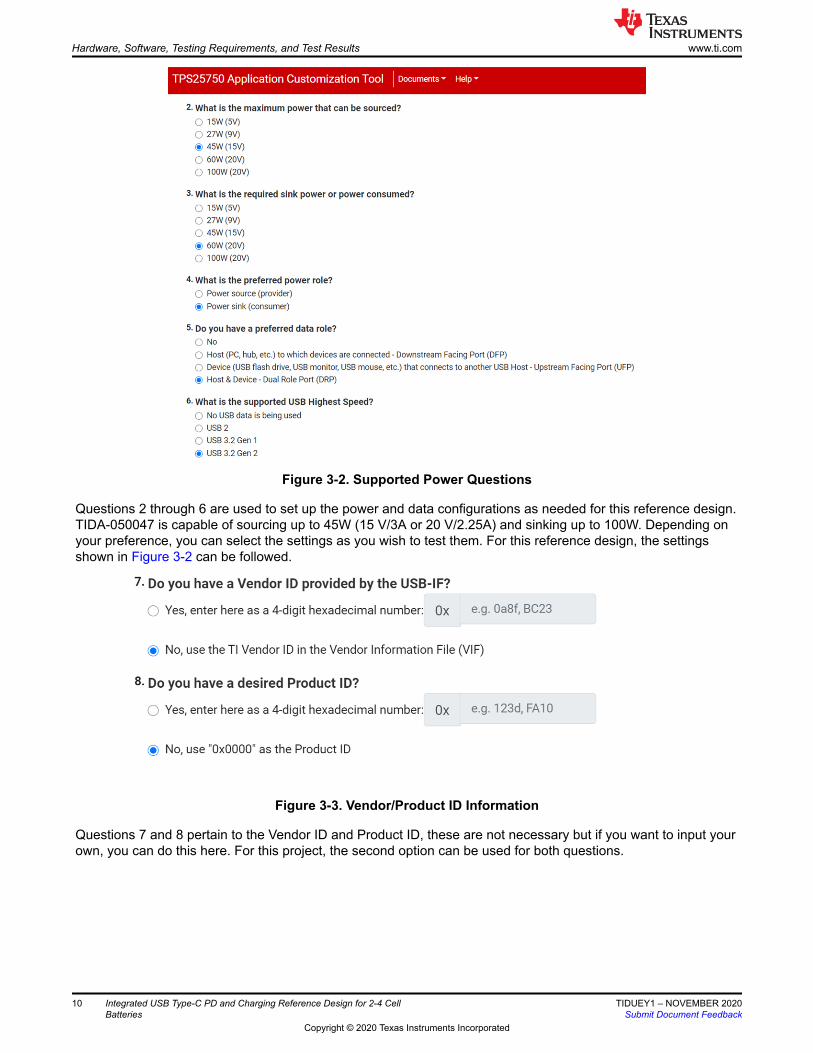
Figure 3-2. Supported Power Questions
Questions 2 through 6 are used to set up the power and data configurations as needed for this reference design.TIDA-050047 is capable of sourcing up to 45W (15 V/3A or 20 V/2.25A) and sinking up to 100W. Depending onyour preference, you can select the settings as you wish to test them. For this reference design, the settingsshown in Figure 3-2 can be followed.
Figure 3-3. Vendor/Product ID Information
Questions 7 and 8 pertain to the Vendor ID and Product ID, these are not necessary but if you want to input yourown, you can do this here. For this project, the second option can be used for both questions.
Hardware, Software, Testing Requirements, and Test Results www.ti.com
10 Integrated USB Type-C PD and Charging Reference Design for 2-4 CellBatteries
TIDUEY1 – NOVEMBER 2020Submit Document Feedback
Copyright © 2020 Texas Instruments Incorporated

Figure 3-4. Battery Charger Questions
The last section asks questions regarding the battery charger configuration. For this design, the battery chargerused is the BQ25792, so the first option can be selected here. The following questions can be filled in to howyou would want to test. For example
• Battery charging voltage you can choose to input 12 V for a 3s battery• Battery charging current can be set to 3 A• Charge termination current will be set to a low 400mA, this is the current that the battery will charge at once it
has reached almost full capacity• Pre-charge current depends on the battery charger that is chosen, for the BQ25792, 400mA can be chosen
www.ti.com Hardware, Software, Testing Requirements, and Test Results
TIDUEY1 – NOVEMBER 2020Submit Document Feedback
Integrated USB Type-C PD and Charging Reference Design for 2-4 CellBatteries
11
Copyright © 2020 Texas Instruments Incorporated
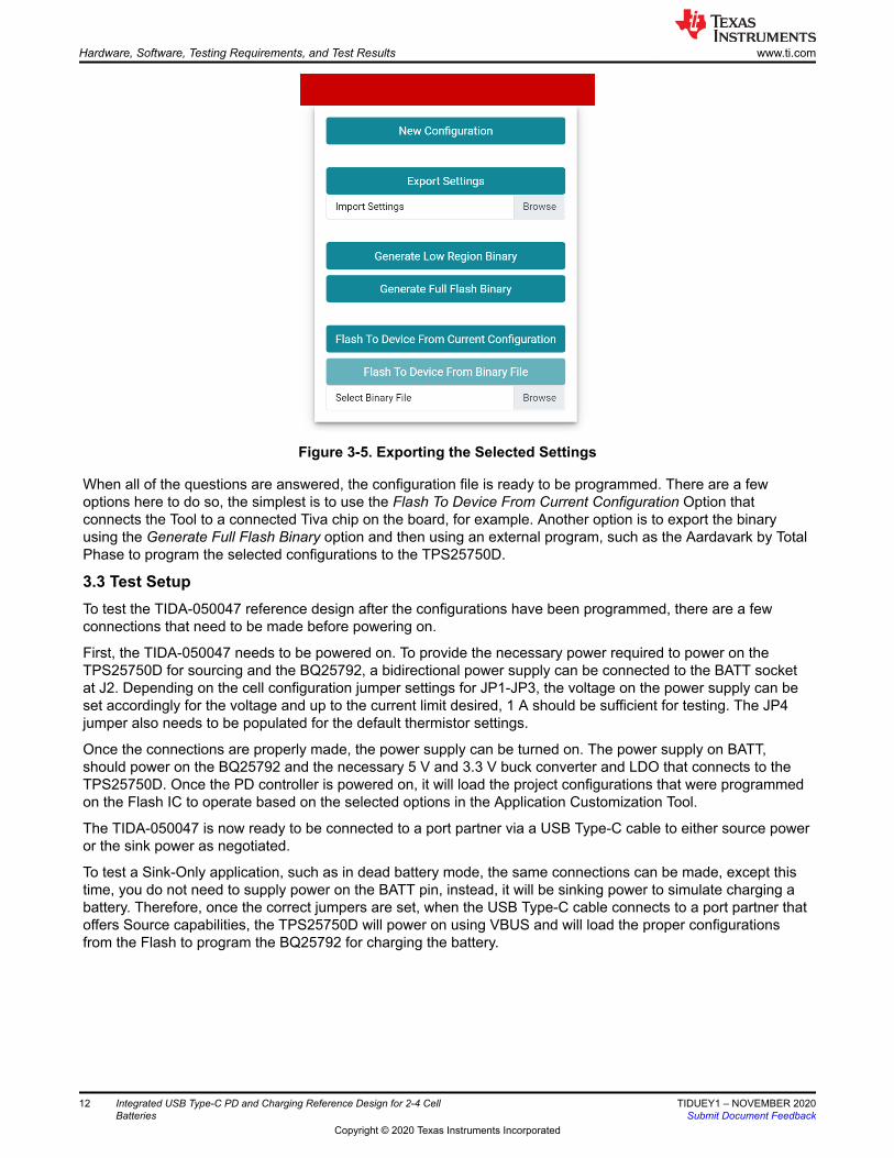
Figure 3-5. Exporting the Selected Settings
When all of the questions are answered, the configuration file is ready to be programmed. There are a fewoptions here to do so, the simplest is to use the Flash To Device From Current Configuration Option thatconnects the Tool to a connected Tiva chip on the board, for example. Another option is to export the binaryusing the Generate Full Flash Binary option and then using an external program, such as the Aardavark by TotalPhase to program the selected configurations to the TPS25750D.
3.3 Test SetupTo test the TIDA-050047 reference design after the configurations have been programmed, there are a fewconnections that need to be made before powering on.
First, the TIDA-050047 needs to be powered on. To provide the necessary power required to power on theTPS25750D for sourcing and the BQ25792, a bidirectional power supply can be connected to the BATT socketat J2. Depending on the cell configuration jumper settings for JP1-JP3, the voltage on the power supply can beset accordingly for the voltage and up to the current limit desired, 1 A should be sufficient for testing. The JP4jumper also needs to be populated for the default thermistor settings.
Once the connections are properly made, the power supply can be turned on. The power supply on BATT,should power on the BQ25792 and the necessary 5 V and 3.3 V buck converter and LDO that connects to theTPS25750D. Once the PD controller is powered on, it will load the project configurations that were programmedon the Flash IC to operate based on the selected options in the Application Customization Tool.
The TIDA-050047 is now ready to be connected to a port partner via a USB Type-C cable to either source poweror the sink power as negotiated.
To test a Sink-Only application, such as in dead battery mode, the same connections can be made, except thistime, you do not need to supply power on the BATT pin, instead, it will be sinking power to simulate charging abattery. Therefore, once the correct jumpers are set, when the USB Type-C cable connects to a port partner thatoffers Source capabilities, the TPS25750D will power on using VBUS and will load the proper configurationsfrom the Flash to program the BQ25792 for charging the battery.
Hardware, Software, Testing Requirements, and Test Results www.ti.com
12 Integrated USB Type-C PD and Charging Reference Design for 2-4 CellBatteries
TIDUEY1 – NOVEMBER 2020Submit Document Feedback
Copyright © 2020 Texas Instruments Incorporated
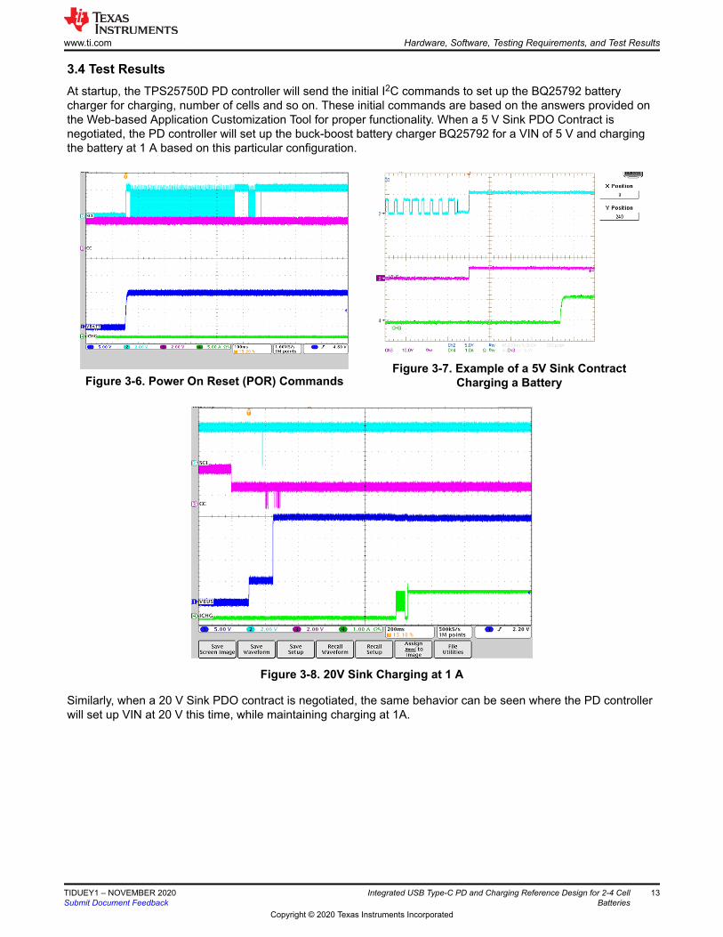
3.4 Test ResultsAt startup, the TPS25750D PD controller will send the initial I2C commands to set up the BQ25792 batterycharger for charging, number of cells and so on. These initial commands are based on the answers provided onthe Web-based Application Customization Tool for proper functionality. When a 5 V Sink PDO Contract isnegotiated, the PD controller will set up the buck-boost battery charger BQ25792 for a VIN of 5 V and chargingthe battery at 1 A based on this particular configuration.
Figure 3-6. Power On Reset (POR) CommandsFigure 3-7. Example of a 5V Sink Contract
Charging a Battery
Figure 3-8. 20V Sink Charging at 1 A
Similarly, when a 20 V Sink PDO contract is negotiated, the same behavior can be seen where the PD controllerwill set up VIN at 20 V this time, while maintaining charging at 1A.
www.ti.com Hardware, Software, Testing Requirements, and Test Results
TIDUEY1 – NOVEMBER 2020Submit Document Feedback
Integrated USB Type-C PD and Charging Reference Design for 2-4 CellBatteries
13
Copyright © 2020 Texas Instruments Incorporated
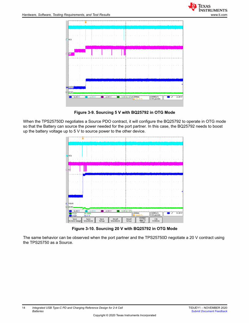
Figure 3-9. Sourcing 5 V with BQ25792 in OTG Mode
When the TPS25750D negotiates a Source PDO contract, it will configure the BQ25792 to operate in OTG modeso that the Battery can source the power needed for the port partner. In this case, the BQ25792 needs to boostup the battery voltage up to 5 V to source power to the other device.
Figure 3-10. Sourcing 20 V with BQ25792 in OTG Mode
The same behavior can be observed when the port partner and the TPS25750D negotiate a 20 V contract usingthe TPS25750 as a Source.
Hardware, Software, Testing Requirements, and Test Results www.ti.com
14 Integrated USB Type-C PD and Charging Reference Design for 2-4 CellBatteries
TIDUEY1 – NOVEMBER 2020Submit Document Feedback
Copyright © 2020 Texas Instruments Incorporated

Figure 3-11. Power Role Swap from Source to Sink
One of the features for USB Type-C PD Controllers, such as the TPS25750D is the ability to perform Power RoleSwaps depending on when certain conditions change. In the corresponding figure, initially the sourcing can beobserved as VBUS is at 20 V but the charging current is at 0 V, then a reset or renegotiation occurs where thePD controller needs to become a Sink and both devices accept this change. Therefore, VBUS goes to 0 V andthen negotiates a 20 V Sink PDO contract. Once the Power Role Swap is done, the TPS25750D configures theBQ25792 for charging mode to charge at 1 A, which can be seen at the end of the capture.
Figure 3-12. Power Role Swap from Sink to Source
Similarly, the same can be done in reverse order, going from the TPS25750D being a Sink and charging thebattery, to renegotiating a Sourcing contract with the port partner and supplying the 20 V using the BQ25792.
www.ti.com Hardware, Software, Testing Requirements, and Test Results
TIDUEY1 – NOVEMBER 2020Submit Document Feedback
Integrated USB Type-C PD and Charging Reference Design for 2-4 CellBatteries
15
Copyright © 2020 Texas Instruments Incorporated
4 Design and Documentation Support4.1 Design Files
4.1.1 Schematics
To download the schematics, see the design files at TIDA-050047.
4.1.2 BOM
To download the bill of materials (BOM), see the design files at TIDA-050047.
4.1.3 Altium Project
To download the Altium Designer® project files, see the design files at TIDA-050047.
4.2 SoftwareTo download the software binary file needed to configure the TPS25750D for this reference design, see thedesign files at TIDA-050047.
4.3 Documentation Support
1. Texas Instruments, TPS25750 USB Type-C and USB PD Controller with Integrated Power Switches datasheet
2. Texas Instruments, BQ25792 I2C Controlled, 1-4 Cell, 5-A Buck Boost Charger, Dual-Input Selector datasheet
3. Texas Instruments, Web-Based Application Customization Tool Guide for TPS25750
4.4 Support ResourcesTI E2E™ support forums are an engineer's go-to source for fast, verified answers and design help — straightfrom the experts. Search existing answers or ask your own question to get the quick design help you need.
Linked content is provided "AS IS" by the respective contributors. They do not constitute TI specifications and donot necessarily reflect TI's views; see TI's Terms of Use.
4.5 TrademarksTI E2E™ are trademarks of Texas Instruments.USB Type-C® is a registered trademark of Texas Instruments.All trademarks are the property of their respective owners.
Design and Documentation Support www.ti.com
16 Integrated USB Type-C PD and Charging Reference Design for 2-4 CellBatteries
TIDUEY1 – NOVEMBER 2020Submit Document Feedback
Copyright © 2020 Texas Instruments Incorporated
5 About the AuthorHari Patel is an Applications Engineer for Texas Instruments where he is responsible for supporting USB Type-Cand PD controllers. Hari earned both his Bachelor of Science and Master of Science in Electrical Engineeringfrom The Univeristy of Florida in Gainesville, FL.
www.ti.com About the Author
TIDUEY1 – NOVEMBER 2020Submit Document Feedback
Integrated USB Type-C PD and Charging Reference Design for 2-4 CellBatteries
17
Copyright © 2020 Texas Instruments Incorporated

IMPORTANT NOTICE AND DISCLAIMER
TI PROVIDES TECHNICAL AND RELIABILITY DATA (INCLUDING DATASHEETS), DESIGN RESOURCES (INCLUDING REFERENCE DESIGNS), APPLICATION OR OTHER DESIGN ADVICE, WEB TOOLS, SAFETY INFORMATION, AND OTHER RESOURCES “AS IS” AND WITH ALL FAULTS, AND DISCLAIMS ALL WARRANTIES, EXPRESS AND IMPLIED, INCLUDING WITHOUT LIMITATION ANY IMPLIED WARRANTIES OF MERCHANTABILITY, FITNESS FOR A PARTICULAR PURPOSE OR NON-INFRINGEMENT OF THIRD PARTY INTELLECTUAL PROPERTY RIGHTS.These resources are intended for skilled developers designing with TI products. You are solely responsible for (1) selecting the appropriate TI products for your application, (2) designing, validating and testing your application, and (3) ensuring your application meets applicable standards, and any other safety, security, or other requirements. These resources are subject to change without notice. TI grants you permission to use these resources only for development of an application that uses the TI products described in the resource. Other reproduction and display of these resources is prohibited. No license is granted to any other TI intellectual property right or to any third party intellectual property right. TI disclaims responsibility for, and you will fully indemnify TI and its representatives against, any claims, damages, costs, losses, and liabilities arising out of your use of these resources.TI’s products are provided subject to TI’s Terms of Sale (www.ti.com/legal/termsofsale.html) or other applicable terms available either on ti.com or provided in conjunction with such TI products. TI’s provision of these resources does not expand or otherwise alter TI’s applicable warranties or warranty disclaimers for TI products.
Mailing Address: Texas Instruments, Post Office Box 655303, Dallas, Texas 75265Copyright © 2020, Texas Instruments Incorporated
Recommended