Intro to Right of Way Mappingin
Civil 3D 2014
Justin L. Evers, PSM
FDOT Central Office

Topics
Settings
Drawing Lines and Curves
Labeling
Coordinate Geometry (COGO)
Best-Fit Line
Paper Space
Rotating Layouts
Inserting Images
Design Center
Annotation Scale

Templates
DOT has pre-made drawing templates
Templates include:
Linetypes
Label styles
Point styles
Fonts
Blocks
Sheet borders

Drawing Settings
State Plane
Feet
Degrees

Sanity Settings
The following settings will make Civil 3D easier and less stressful:
MSLTSCALE – This is the model space linetype scale. This setting makes your linetypes react to the annotation scale. SET TO 1.
PSLTSCALE – This is the paper space linetype scale. SET TO 1 for the same reasons as MSLTSCALE.
LTSCALE – Controls the overall line scaling. SET TO 1.

Sanity Settings
The following settings will make Civil 3D easier and less stressful:
LAYEREVALCTL – Controls pop-ups that happen when new layers are introduced into the drawing. Happens when you copy objects in or XREF in drawings. SET TO 0 so you won’t see them.
GEOMARKERVISIBILITY – Appears when you set the coordinate system in a drawing. Looks like a block but it’s not really there and you can’t select it or delete it. SET TO 0 so it will go away.

Workspace Settings
Civil 3D comes with default workspaces for you to use
Civil 3D
Drafting and Annotation
3D Modeling
Planning and Analysis
Default workspaces are not geared towards surveying and mapping
Workspaces are highly customizable

Toolspace
New to Civil 3D
Command Central
Lets you:
Edit and delete points
Edit label styles
Edit alignments
Import and export points

Properties
Information Center
Tells you:
Line length
Coordinates
Layer
Linetype
Color
Arc length
Radius

Drawing Lines
Lines can be drawn freehand, between points, by coordinate, by bearing or azimuth, or by angle
Line commands are located in the Drawsection of the Home ribbon

Drawing Lines
Common methods:
Line by Northing/Easting
Line by Bearing
Line by Angle
Line by Station/Offset
Line from Extension
Line by End of Object
Line Perpendicular from Point

Drawing Curves
Curves can be drawn by point method or by mathematical method
Both methods are located under the Draw section of the Home ribbon

Drawing Curves by Point Method
Select the 3-Point icon and choose the method you want to use
This method does not work unless you have points along the curve or you know the beginning, end, and center of the curve
Works well for topo and as-builts but not for boundary and right of way

Drawing Curves - Mathematical Method
Select the Curves icon and then Create Curve from End of Object
This will enable you to draw a curve using mathematical properties such as delta, length, radius, chord, etc.
This is the method used for drawing curves for a baseline, centerline or legal description

Labeling Lines and Curves
DOT has included pre-defined label styles for you to use.

COGO
Points can be created by a variety of methods in Civil 3D depending on the scenario
Common methods:
Manual
Coordinate
Along Lines and Curves
Bearing and Distance
Angle and Distance

Best-Fit Line
Useful when trying to establish one common line for a row of points
Uses least squares to create lines and arcs
Will work for curves too

Paper Space
Paper space is used for:
Sheet borders
Notes
Legends
North arrows and scales
Nothing in paper space shows up in model space
Nothing in paper space shows up in another sheet’s paper space

Paper Space
Paper space usually has an active viewport which enables you to see into model space
Paper space has a scale of 1:1
Objects scaled for model space will look huge in paper space
Objects scaled for paper space will look tiny in model space
Borders, legends, north arrows, and scales are scaled for paper space in FDOT R/W templates

Rotating Layouts
There are several different ways to rotate in Civil 3D
ALIGNSPACE is the easiest and safest way
DVIEW does the same thing as ALIGNSPACE, but is more complicated
You should never rotate the UCS in model space.

Rotating Layouts - ALIGNSPACE
Pro
Keeps everything oriented to the World Coordinate System (WCS)
Con
Text is not aligned

WCS vs UCS
WCS – World Coordinate System
Is unchangeable
Works on State Plane Coordinates
UCS – User Coordinate System
Can be changed
- New initial point set
- New rotation

Rotating the UCS
NEVER ROTATE THE UCS IN MODEL SPACE!!!
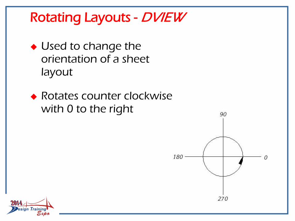
Rotating Layouts - DVIEW
Used to change the orientation of a sheet layout
Rotates counter clockwise with 0 to the right

Rotating Layouts - DVIEW
Must be in model space in a particular sheet layout
Viewport must be unlocked
Use DVIEW command
Inside the DVIEW command, use the TWist option
You must know the angle required to rotate your baseline to zero (zero being to the right)
You can use negative (-) angles

Inserting Images
Inserted image
MAPIINSERT, IINSERT
References the entire image (XREF)
Slows down AutoCAD
FDO connected image
DATACONNECT or MAPCONNECT
Links an image
Only displays the area being shown at any given time
“Faster” than an inserted image

Design Center
Design Center is an easy way to manage drawing properties like:
linetypes
blocks
layers
Provides an easy, visual way to insert blocks

Annotation Scale
Annotation scale is a powerful tool that allows you to set text and blocks to a certain size regardless of the drawing scale.
For example, if you set your text to print at .1” high in paper space, AutoCAD will hold that size no matter what scale you print in.
DOT has set the appropriate items to annotate in the provided drawing templates.

Annotation Scale
Allows text to show on different sheets at the correct scale for that sheet
The same text can show up at .1” for 40 scale detail sheets and .05” for 100 scale overall sheets
Eliminates the need for multiple pieces of the same text for sheets of different scales
Recommended