Introduction topreparative chromatographytechniques and membrane
separation technologies
Edit Székely
Modern separation technologies course, 2019, BME
1
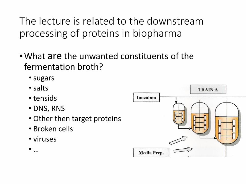
The lecture is related to the downstreamprocessing of proteins in biopharma
•What are the unwanted constituents of thefermentation broth? • sugars• salts• tensids• DNS, RNS• Other then target proteins• Broken cells• viruses• …
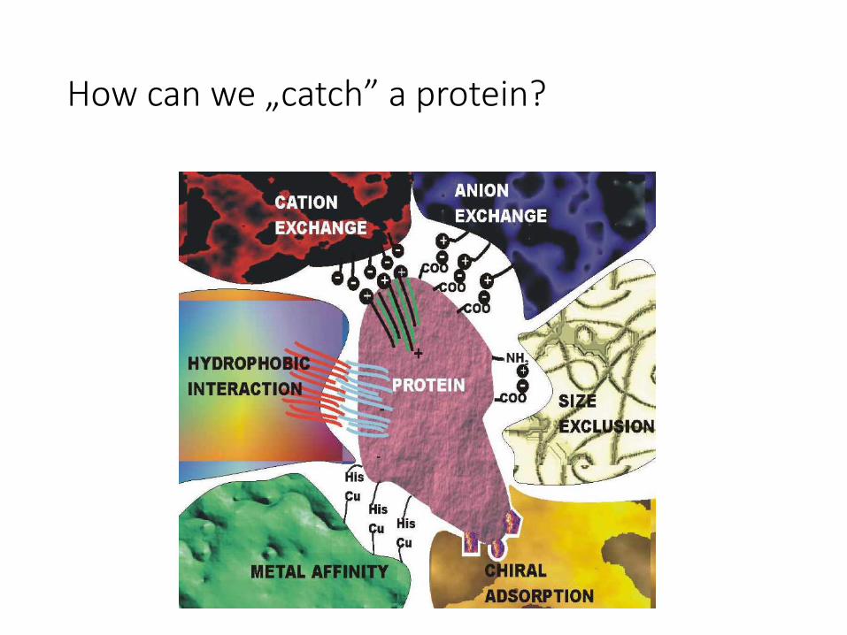
How can we „catch” a protein?
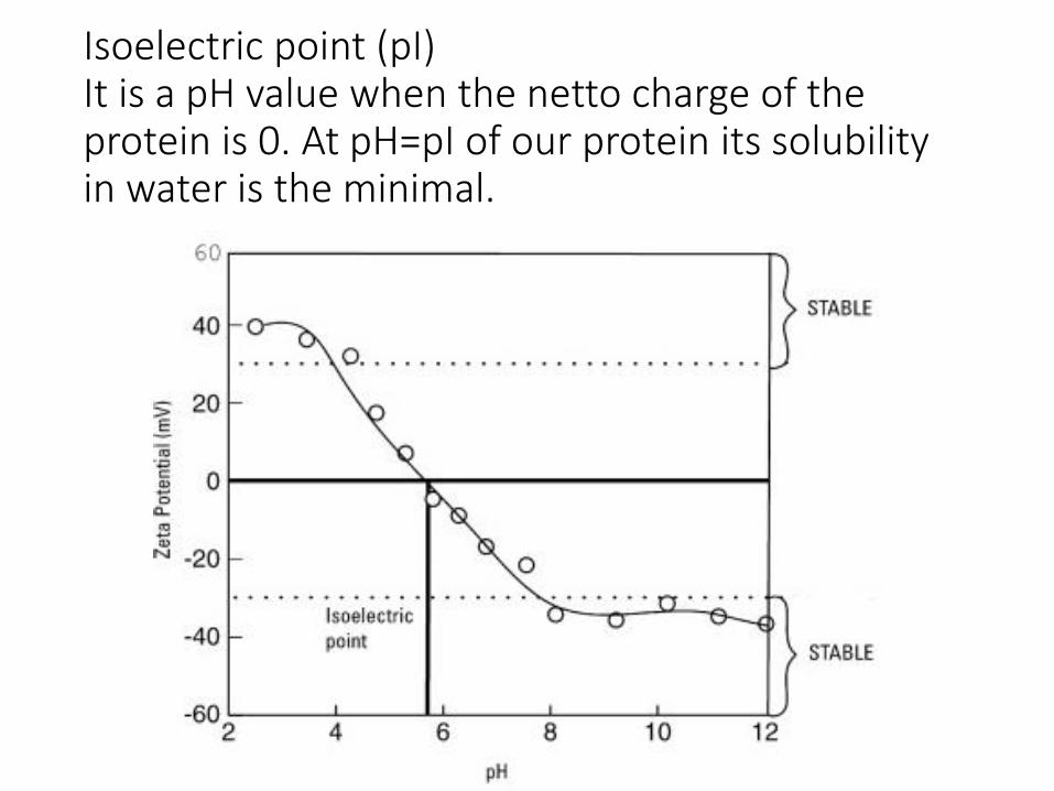
Isoelectric point (pI)It is a pH value when the netto charge of theprotein is 0. At pH=pI of our protein its solubilityin water is the minimal.
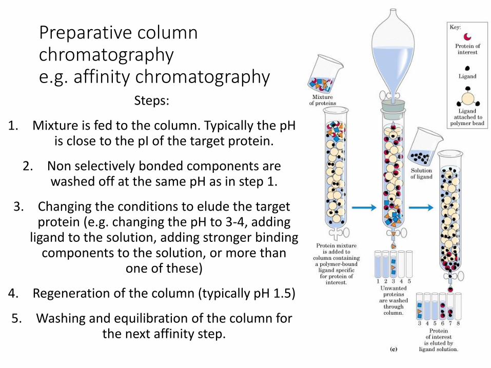
Preparative columnchromatographye.g. affinity chromatography
Steps:
1. Mixture is fed to the column. Typically the pH is close to the pI of the target protein.
2. Non selectively bonded components are washed off at the same pH as in step 1.
3. Changing the conditions to elude the target protein (e.g. changing the pH to 3-4, adding
ligand to the solution, adding stronger binding components to the solution, or more than
one of these)
4. Regeneration of the column (typically pH 1.5)
5. Washing and equilibration of the column for the next affinity step.
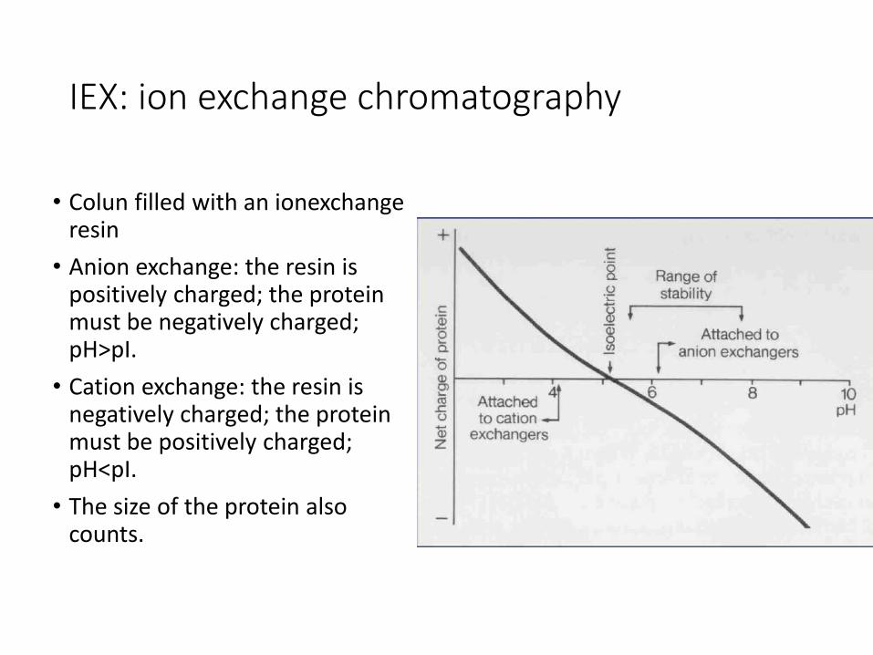
IEX: ion exchange chromatography
• Colun filled with an ionexchangeresin
• Anion exchange: the resin is positively charged; the protein must be negatively charged; pH>pI.
• Cation exchange: the resin is negatively charged; the protein must be positively charged; pH<pI.
• The size of the protein alsocounts.
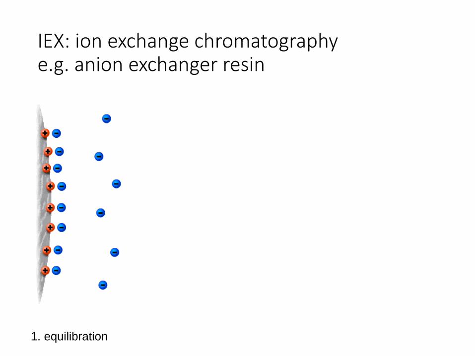
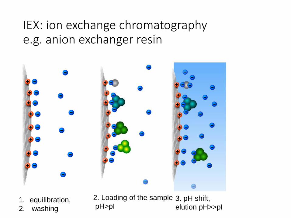
IEX: ion exchange chromatographye.g. anion exchanger resin
1. equilibration
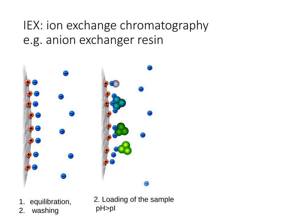
IEX: ion exchange chromatographye.g. anion exchanger resin
1. equilibration,
2. washing
2. Loading of the sample
pH>pI
IEX: ion exchange chromatographye.g. anion exchanger resin
3. pH shift,
elution pH>>pI1. equilibration,
2. washing
2. Loading of the sample
pH>pI
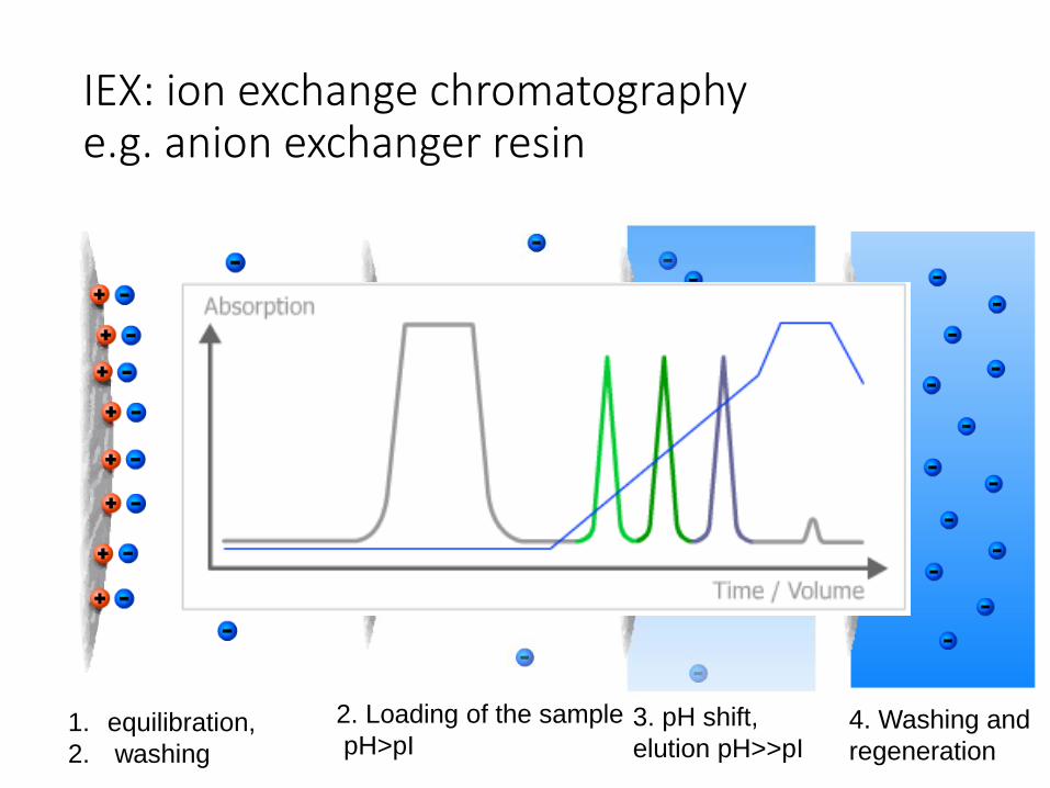
IEX: ion exchange chromatographye.g. anion exchanger resin
4. Washing and
regeneration
3. pH shift,
elution pH>>pI1. equilibration,
2. washing
2. Loading of the sample
pH>pI
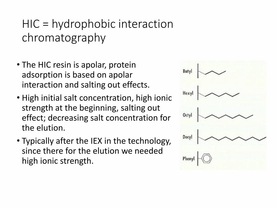
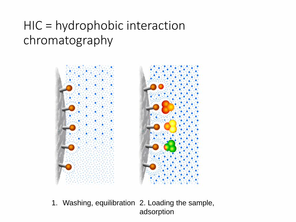
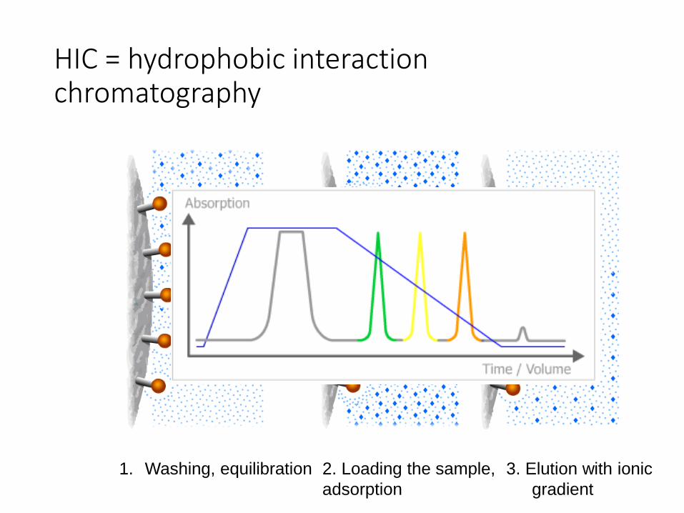
HIC = hydrophobic interactionchromatography
• The HIC resin is apolar, protein adsorption is based on apolarinteraction and salting out effects.
• High initial salt concentration, high ionic strength at the beginning, salting out effect; decreasing salt concentration for the elution.
• Typically after the IEX in the technology, since there for the elution we needed high ionic strength.
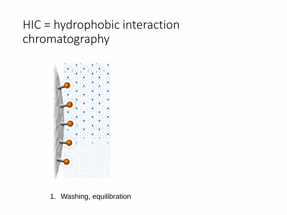
HIC = hydrophobic interactionchromatography
1. Washing, equilibration
HIC = hydrophobic interactionchromatography
2. Loading the sample,
adsorption
1. Washing, equilibration
HIC = hydrophobic interactionchromatography
3. Elution with ionic
gradient
2. Loading the sample,
adsorption
1. Washing, equilibration
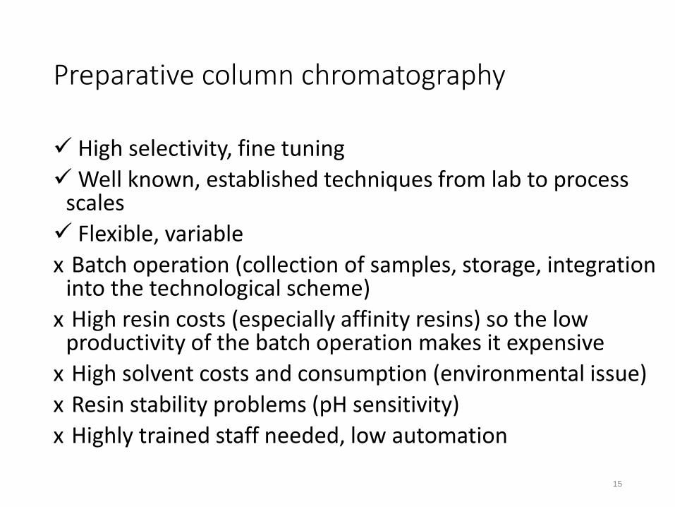
Preparative column chromatography
High selectivity, fine tuning
Well known, established techniques from lab to process scales
Flexible, variable
x Batch operation (collection of samples, storage, integration into the technological scheme)
x High resin costs (especially affinity resins) so the low productivity of the batch operation makes it expensive
x High solvent costs and consumption (environmental issue)
x Resin stability problems (pH sensitivity)
x Highly trained staff needed, low automation
15
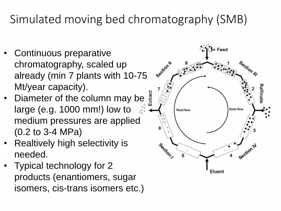
Simulated moving bed chromatography (SMB)
• Continuous preparative
chromatography, scaled up
already (min 7 plants with 10-75
Mt/year capacity).
• Diameter of the column may be
large (e.g. 1000 mm!) low to
medium pressures are applied
(0.2 to 3-4 MPa)
• Realtively high selectivity is
needed.
• Typical technology for 2
products (enantiomers, sugar
isomers, cis-trans isomers etc.)
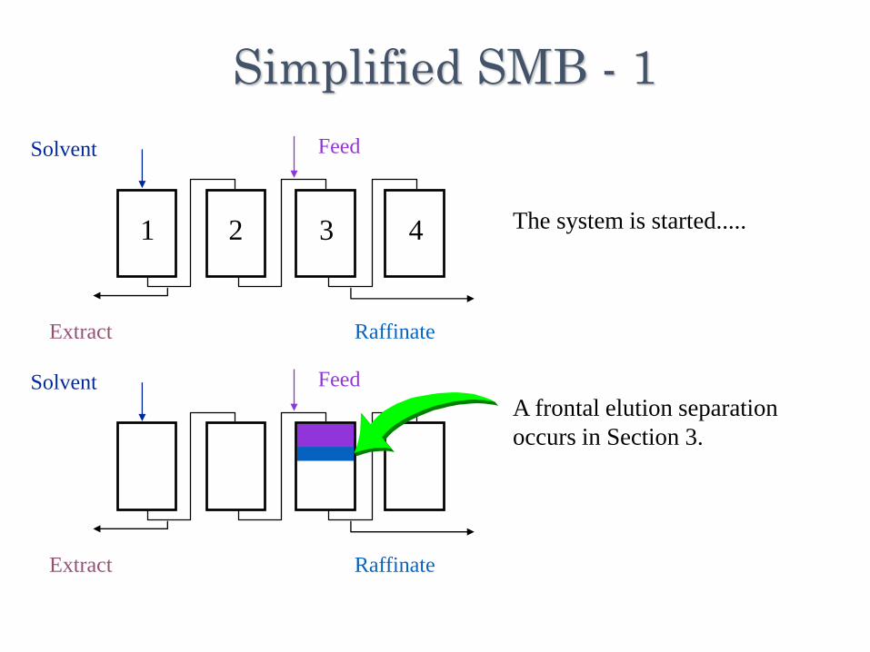
Simplified SMB - 1
FeedSolvent
Extract Raffinate
FeedSolvent
Extract Raffinate
The system is started.....
A frontal elution separation
occurs in Section 3.
1 2 3 4
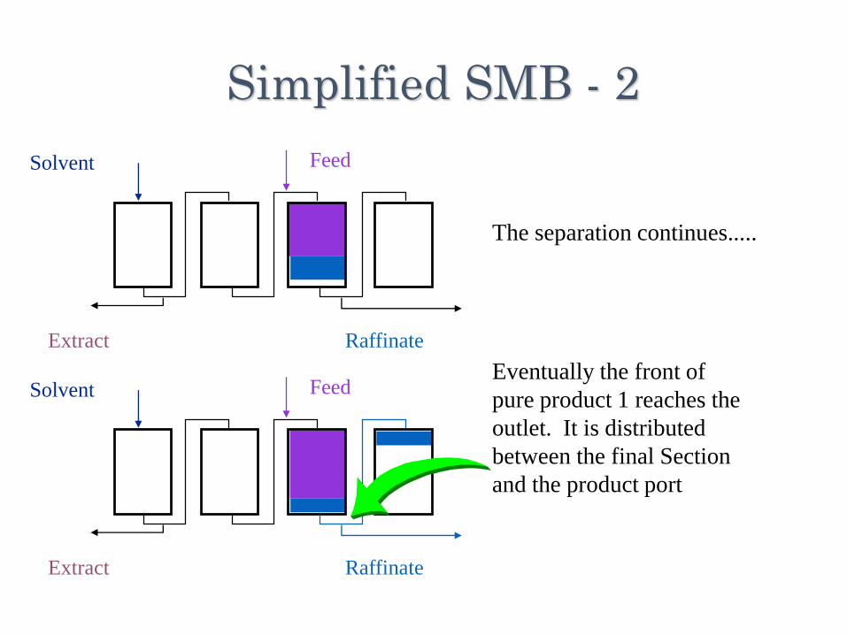
Simplified SMB - 2
FeedSolvent
Extract Raffinate
FeedSolvent
Extract Raffinate
The separation continues.....
Eventually the front of
pure product 1 reaches the
outlet. It is distributed
between the final Section
and the product port
FeedSolvent
Extract Raffinate
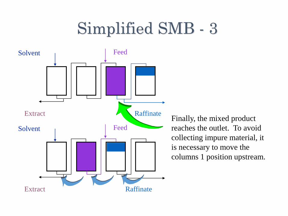
Simplified SMB - 3
FeedSolvent
Extract Raffinate
Finally, the mixed product
reaches the outlet. To avoid
collecting impure material, it
is necessary to move the
columns 1 position upstream.
FeedSolvent
Extract Raffinate
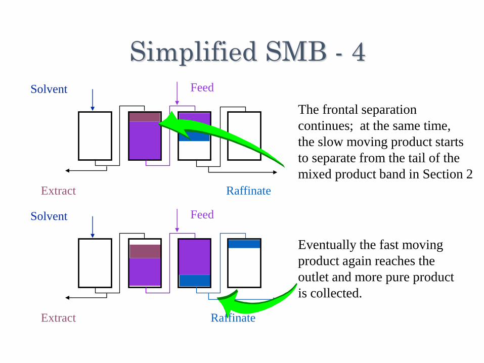
Simplified SMB - 4
FeedSolvent
Extract Raffinate
The frontal separation
continues; at the same time,
the slow moving product starts
to separate from the tail of the
mixed product band in Section 2
Eventually the fast moving
product again reaches the
outlet and more pure product
is collected.
FeedSolvent
ExtractRaffinate
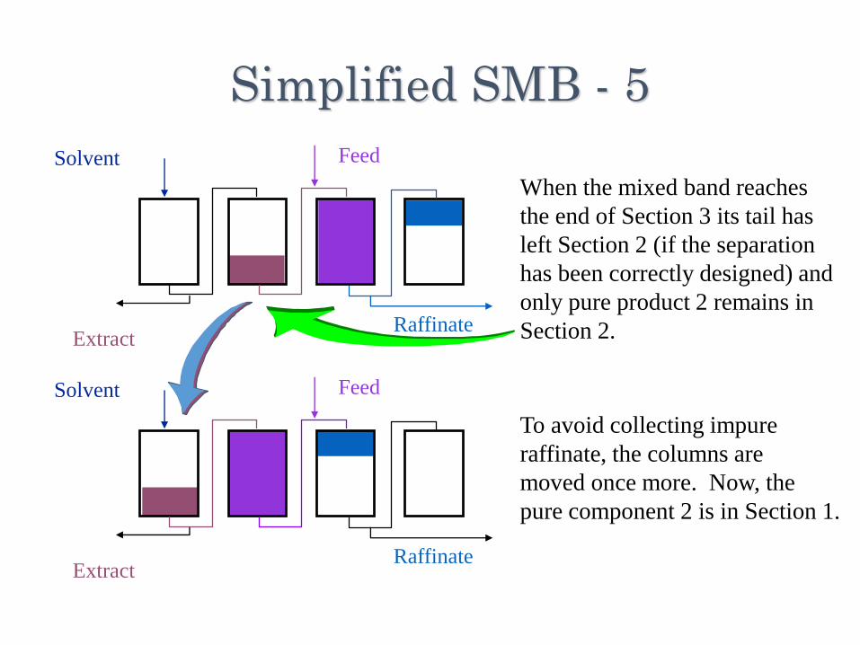
Simplified SMB - 5
When the mixed band reaches
the end of Section 3 its tail has
left Section 2 (if the separation
has been correctly designed) and
only pure product 2 remains in
Section 2.
FeedSolvent
ExtractRaffinate
To avoid collecting impure
raffinate, the columns are
moved once more. Now, the
pure component 2 is in Section 1.
FeedSolvent
ExtractRaffinate
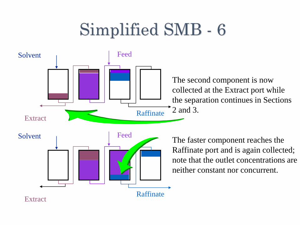
Simplified SMB - 6
FeedSolvent
ExtractRaffinate
The second component is now
collected at the Extract port while
the separation continues in Sections
2 and 3.
The faster component reaches the
Raffinate port and is again collected;
note that the outlet concentrations are
neither constant nor concurrent.
FeedSolvent
ExtractRaffinate
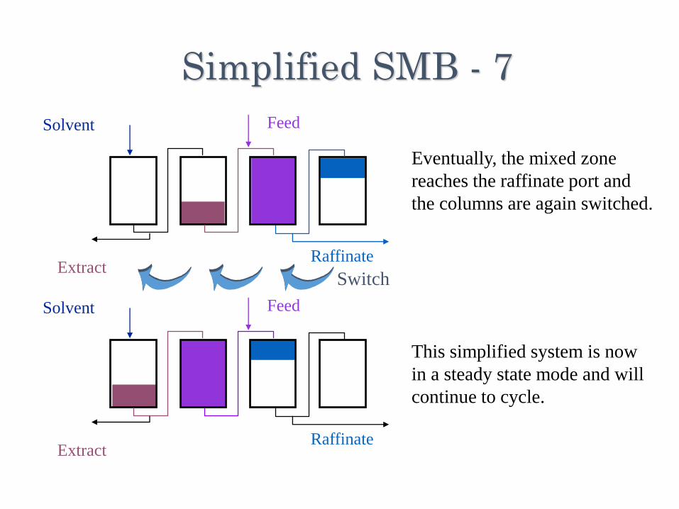
Simplified SMB - 7
FeedSolvent
ExtractRaffinate
Eventually, the mixed zone
reaches the raffinate port and
the columns are again switched.
This simplified system is now
in a steady state mode and will
continue to cycle.
Switch
SMB Optimization
•Independent variables:•Flow rates• Recycle, Desorbent, Raffinate, Extract, Feed
•Period (switching time)
•Procedure:•Educated guess based on batch experiments•Get the system bound, manipulate the flow rates to maximize throughput at required purity
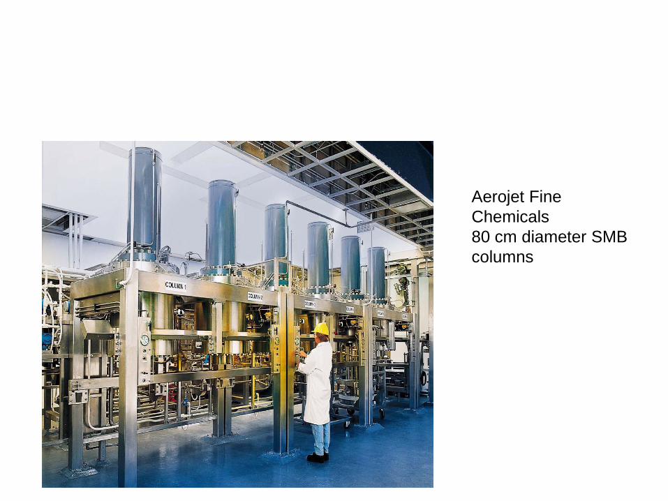
Aerojet Fine
Chemicals
80 cm diameter SMB
columns
MCSGP= MulticolumnCountercurrent Solvent GradientPurification Process
•Similar background as at SMB, but applicable for more than 2 products
•Solvent gradient is introduced additionally to the concept of switching the columns
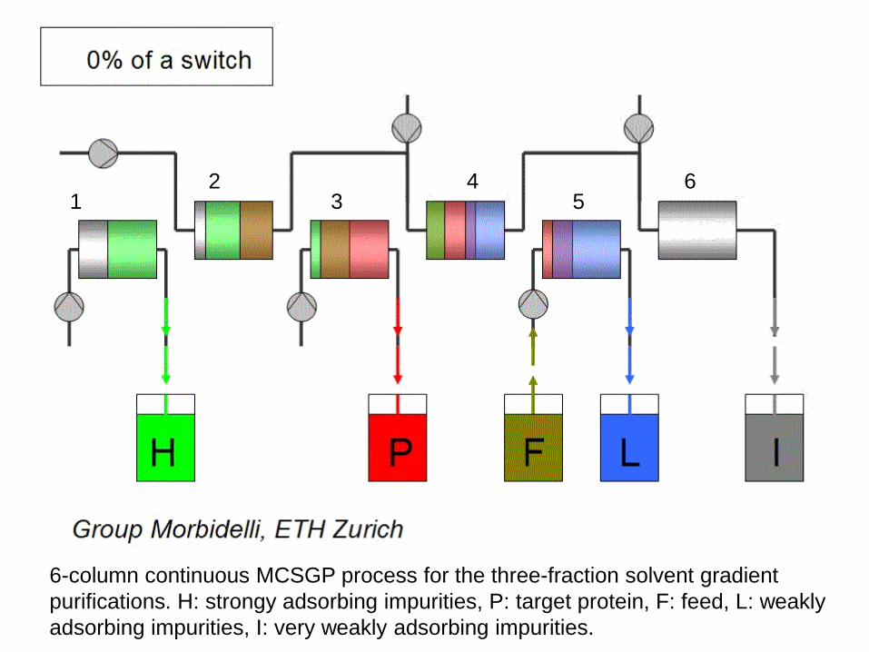
6-column continuous MCSGP process for the three-fraction solvent gradient
purifications. H: strongy adsorbing impurities, P: target protein, F: feed, L: weakly
adsorbing impurities, I: very weakly adsorbing impurities.
12
34
56
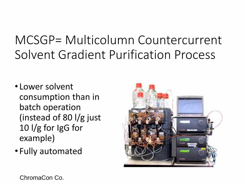
MCSGP= Multicolumn CountercurrentSolvent Gradient Purification Process
• Lower solvent consumption than in batch operation (instead of 80 l/g just 10 l/g for IgG for example)
•Fully automated
ChromaCon Co.
Membrane techniques
29
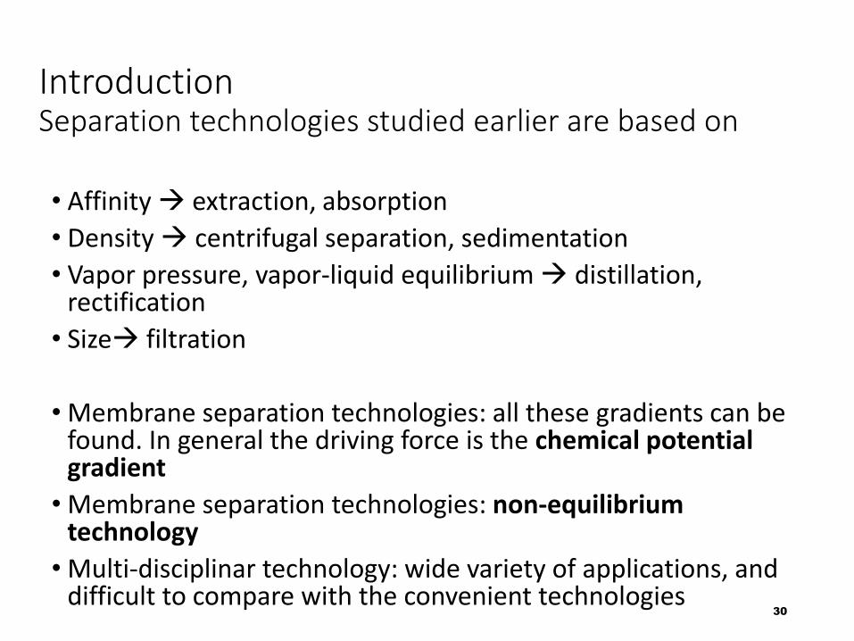
IntroductionSeparation technologies studied earlier are based on
• Affinity extraction, absorption
• Density centrifugal separation, sedimentation
• Vapor pressure, vapor-liquid equilibrium distillation, rectification
• Size filtration
• Membrane separation technologies: all these gradients can be found. In general the driving force is the chemical potential gradient
• Membrane separation technologies: non-equilibrium technology
• Multi-disciplinar technology: wide variety of applications, and difficult to compare with the convenient technologies
30
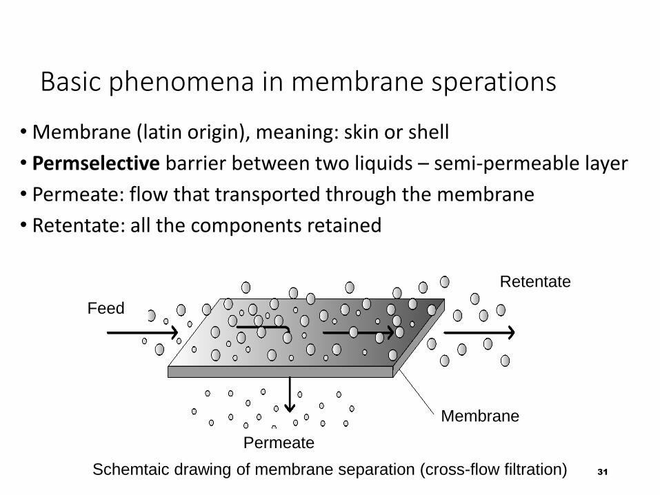
Basic phenomena in membrane sperations
• Membrane (latin origin), meaning: skin or shell
• Permselective barrier between two liquids – semi-permeable layer
• Permeate: flow that transported through the membrane
• Retentate: all the components retained
31Schemtaic drawing of membrane separation (cross-flow filtration)
Feed
Permeate
Membrane
Retentate
The membrane
• Membrane: semi-permeable layer
• Selective layer, permeable only for given components (mainly water)
• Membranes from Nature: plant and animal origin (bladder of pig, filled with wine, and cooled in a well. First observation of diffusion.)
• First artificial membrane: in 1918,by Richárd Zsigmondy
• Applications in wide variety of industrial fields: food and beverage industry, health care, chemical indutry, wastewater treatment etc.
32
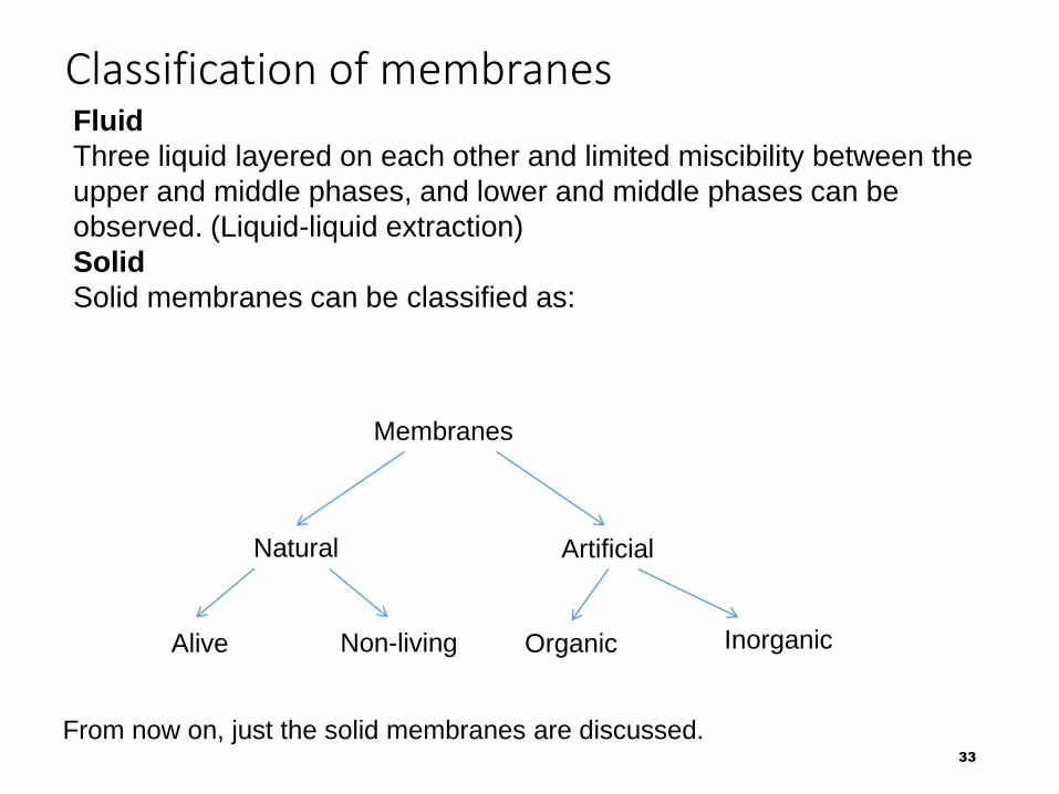
Classification of membranes
33
Fluid
Three liquid layered on each other and limited miscibility between the
upper and middle phases, and lower and middle phases can be
observed. (Liquid-liquid extraction)
Solid
Solid membranes can be classified as:
From now on, just the solid membranes are discussed.
Membranes
Natural Artificial
Alive Non-living Organic Inorganic
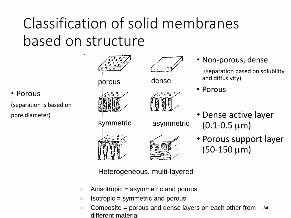
Classification of solid membranes based on structure
heterogén, többrétegű
• Porous
(separation is based on
pore diameter)
34
• Non-porous, dense
(separation based on solubility and diffusivity)
• Porous
• Dense active layer (0.1-0.5 mm)
• Porous support layer (50-150 mm)
}
} Anisotropic = asymmetric and porous
Isotropic = symmetric and porous
Composite = porous and dense layers on each other from
different material
porous dense
symmetric asymmetric
Heterogeneous, multi-layered
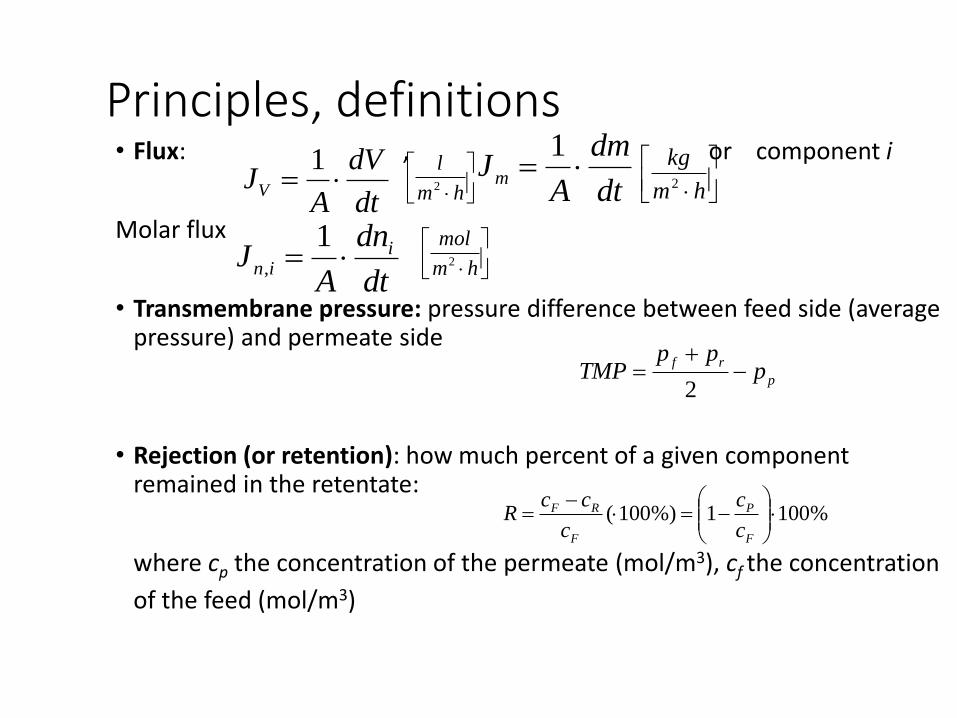
Principles, definitions• Flux: , or component i
Molar flux
• Transmembrane pressure: pressure difference between feed side (averagepressure) and permeate side
• Rejection (or retention): how much percent of a given componentremained in the retentate:
where cp the concentration of the permeate (mol/m3), cf the concentration
of the feed (mol/m3)
dt
dV
AJV
1dt
dm
AJm
1
hm
l2
hm
kg2
dt
dn
AJ i
in 1
,
hm
mol2
p
rfp
ppTMP
2
%1001%)100(
F
P
F
RF
c
c
c
ccR
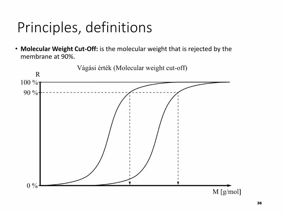
Principles, definitions• Molecular Weight Cut-Off: is the molecular weight that is rejected by the
membrane at 90%.
36
37
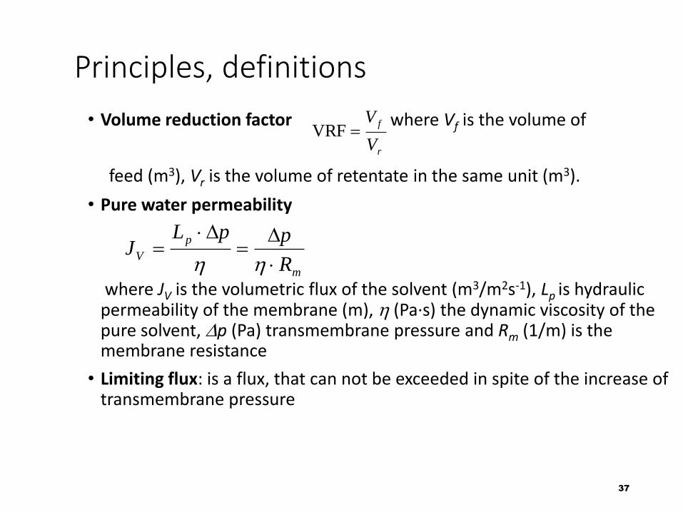
Principles, definitions
• Volume reduction factor where Vf is the volume of
feed (m3), Vr is the volume of retentate in the same unit (m3).
• Pure water permeability
where JV is the volumetric flux of the solvent (m3/m2s-1), Lp is hydraulic permeability of the membrane (m), h (Pa∙s) the dynamic viscosity of the pure solvent, Dp (Pa) transmembrane pressure and Rm (1/m) is the membrane resistance
• Limiting flux: is a flux, that can not be exceeded in spite of the increase of transmembrane pressure
r
f
V
VVRF
m
p
VR
ppLJ
D
D
hh
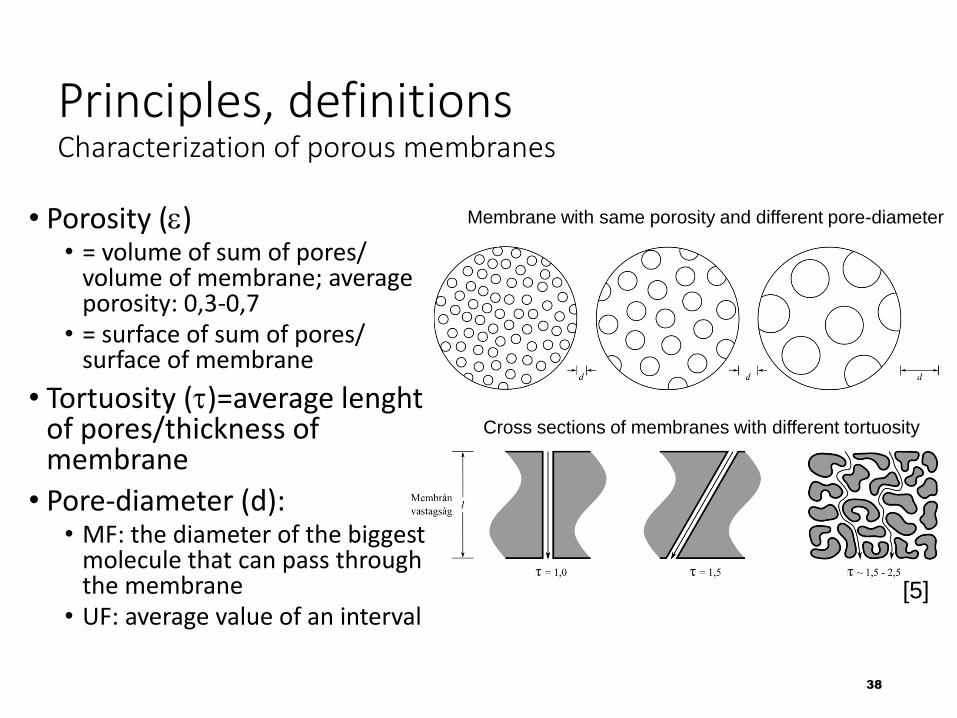
Principles, definitionsCharacterization of porous membranes
• Porosity (e)• = volume of sum of pores/
volume of membrane; average porosity: 0,3-0,7
• = surface of sum of pores/ surface of membrane
• Tortuosity (t)=average lenghtof pores/thickness of membrane
• Pore-diameter (d):• MF: the diameter of the biggest
molecule that can pass through the membrane
• UF: average value of an interval
38
[5]
Membrane with same porosity and different pore-diameter
Cross sections of membranes with different tortuosity
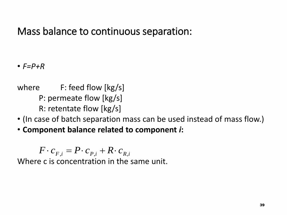
Mass balance to continuous separation:
• F=P+R
where F: feed flow [kg/s]P: permeate flow [kg/s]R: retentate flow [kg/s]
• (In case of batch separation mass can be used instead of mass flow.)• Component balance related to component i:
Where c is concentration in the same unit.
39
iRiPiF cRcPcF ,,,
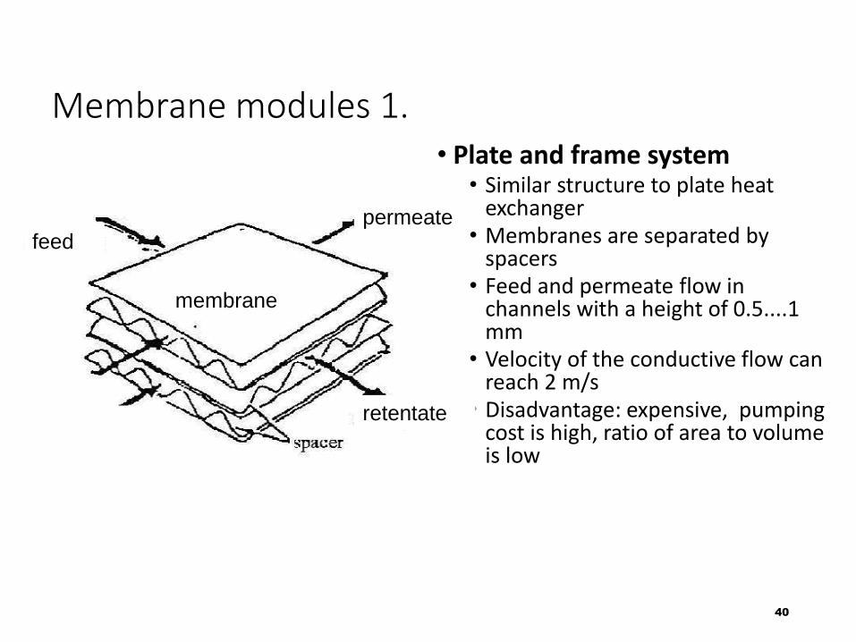
Membrane modules 1.• Plate and frame system
• Similar structure to plate heat exchanger
• Membranes are separated by spacers
• Feed and permeate flow in channels with a height of 0.5....1 mm
• Velocity of the conductive flow can reach 2 m/s
• Disadvantage: expensive, pumping cost is high, ratio of area to volume is low
40
feedpermeate
retentate
membrane
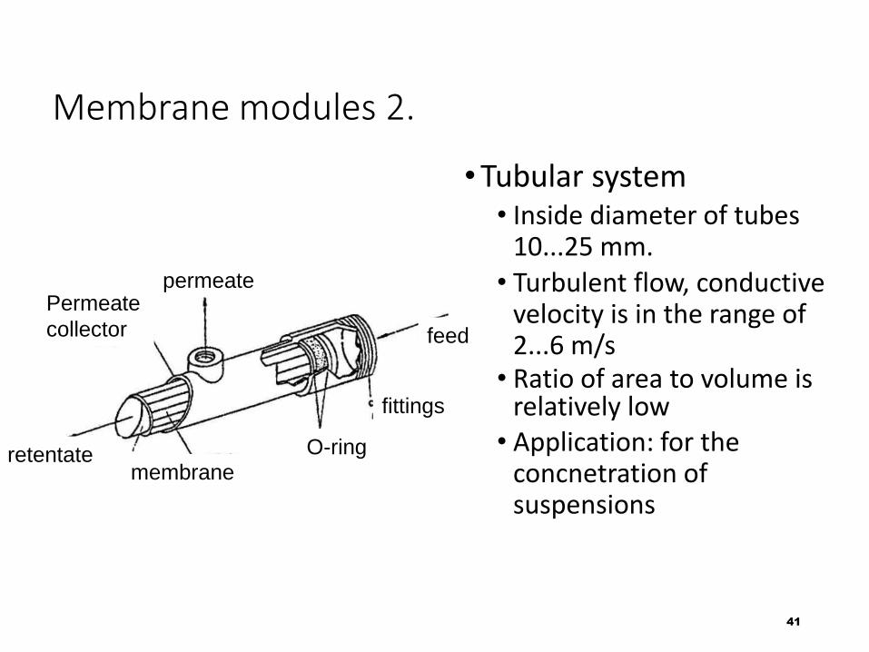
Membrane modules 2.
•Tubular system• Inside diameter of tubes
10...25 mm. • Turbulent flow, conductive
velocity is in the range of 2...6 m/s• Ratio of area to volume is
relatively low • Application: for the
concnetration of suspensions
41
feed
permeate
retentatemembrane
Permeate
collector
O-ring
fittings
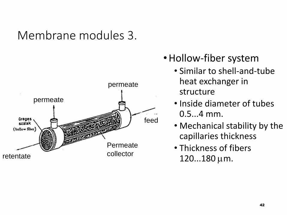
Membrane modules 3.
•Hollow-fiber system• Similar to shell-and-tube
heat exchanger in structure• Inside diameter of tubes
0.5...4 mm.• Mechanical stability by the
capillaries thickness• Thickness of fibers
120...180 mm.
42
permeate
permeate
retentate
feed
Permeate
collector
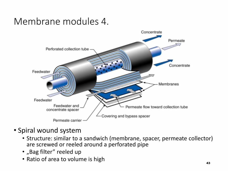
Membrane modules 4.
• Spiral wound system• Structure: similar to a sandwich (membrane, spacer, permeate collector)
are screwed or reeled around a perforated pipe• „Bag filter” reeled up• Ratio of area to volume is high
43
Expections to membranes
• In case of composite membranes: very thin active layer•High permeability and selectivity •Stable and long-life membrane modules•Resistancy to mechanical and chemical stress•Huge area in small volume•No concnetration polarisatin or controllable•Easy cleaning•Cheap (when investing, or during service)
44
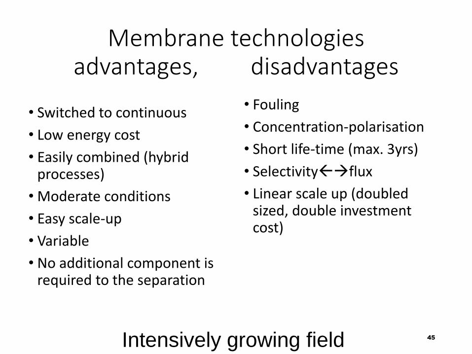
Membrane technologies advantages, disadvantages
• Switched to continuous
• Low energy cost
• Easily combined (hybrid processes)
• Moderate conditions
• Easy scale-up
• Variable
• No additional component is required to the separation
• Fouling
• Concentration-polarisation
• Short life-time (max. 3yrs)
• Selectivityflux
• Linear scale up (doubled sized, double investment cost)
45Intensively growing field
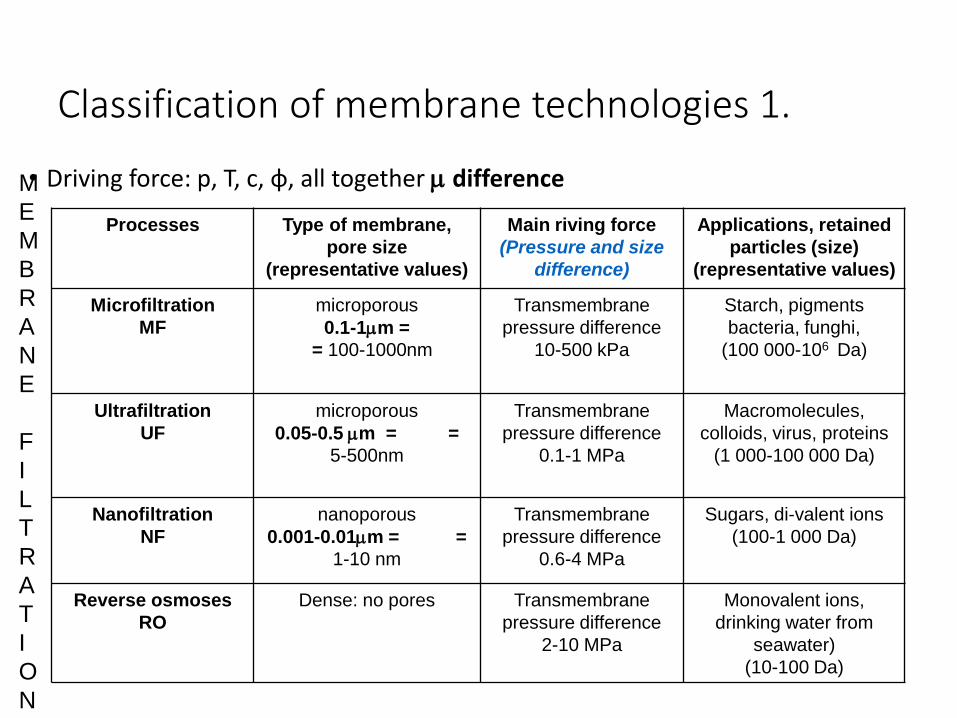
Classification of membrane technologies 1.
• Driving force: p, T, c, ɸ, all together m difference
Processes Type of membrane,
pore size
(representative values)
Main riving force
(Pressure and size
difference)
Applications, retained
particles (size)
(representative values)
Microfiltration
MF
microporous
0.1-1mm =
= 100-1000nm
Transmembrane
pressure difference
10-500 kPa
Starch, pigments
bacteria, funghi,
(100 000-106 Da)
Ultrafiltration
UF
microporous
0.05-0.5 mm = =
5-500nm
Transmembrane
pressure difference
0.1-1 MPa
Macromolecules,
colloids, virus, proteins
(1 000-100 000 Da)
Nanofiltration
NF
nanoporous
0.001-0.01mm = =
1-10 nm
Transmembrane
pressure difference
0.6-4 MPa
Sugars, di-valent ions
(100-1 000 Da)
Reverse osmoses
RO
Dense: no pores Transmembrane
pressure difference
2-10 MPa
Monovalent ions,
drinking water from
seawater)
(10-100 Da)
M
E
M
B
R
A
N
E
F
I
L
T
R
A
T
I
O
N
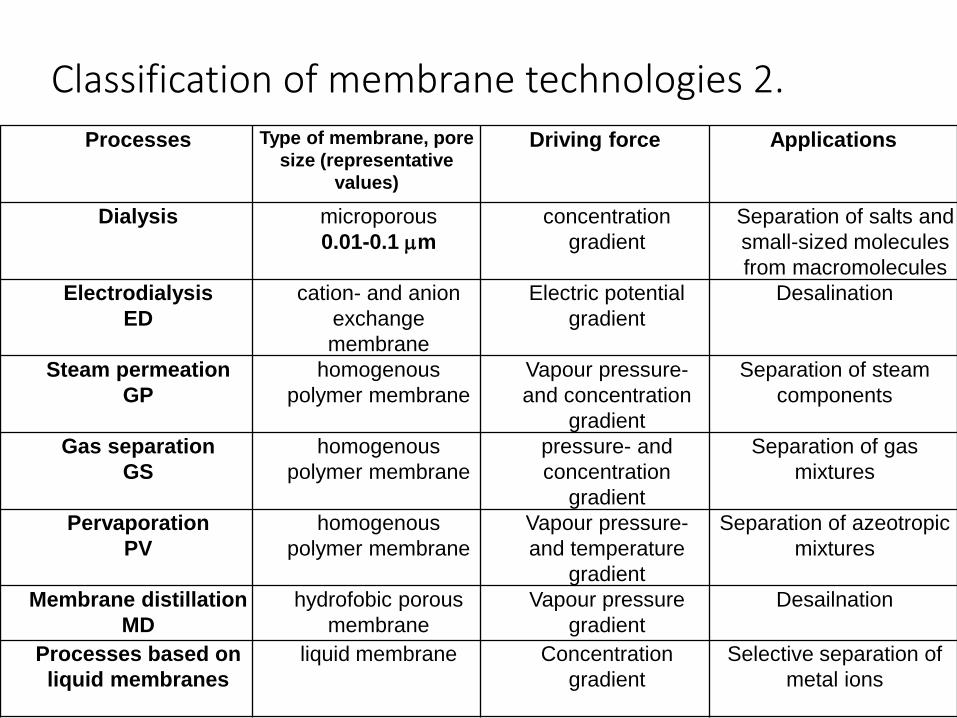
Classification of membrane technologies 2.
Processes Type of membrane, pore
size (representative
values)
Driving force Applications
Dialysis microporous
0.01-0.1 mm
concentration
gradient
Separation of salts and
small-sized molecules
from macromolecules
Electrodialysis
ED
cation- and anion
exchange
membrane
Electric potential
gradient
Desalination
Steam permeation
GP
homogenous
polymer membrane
Vapour pressure-
and concentration
gradient
Separation of steam
components
Gas separation
GS
homogenous
polymer membrane
pressure- and
concentration
gradient
Separation of gas
mixtures
Pervaporation
PV
homogenous
polymer membrane
Vapour pressure-
and temperature
gradient
Separation of azeotropic
mixtures
Membrane distillation
MD
hydrofobic porous
membrane
Vapour pressure
gradient
Desailnation
Processes based on
liquid membranes
liquid membrane Concentration
gradient
Selective separation of
metal ions
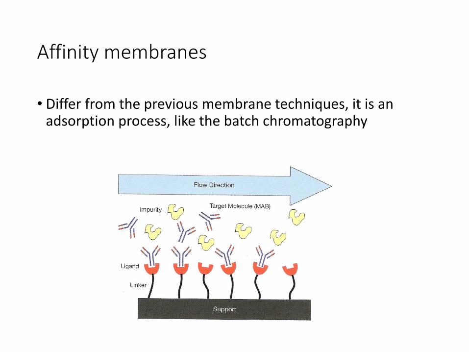
Affinity membranes
• Differ from the previous membrane techniques, it is an adsorption process, like the batch chromatography
II. Affinitás membránok
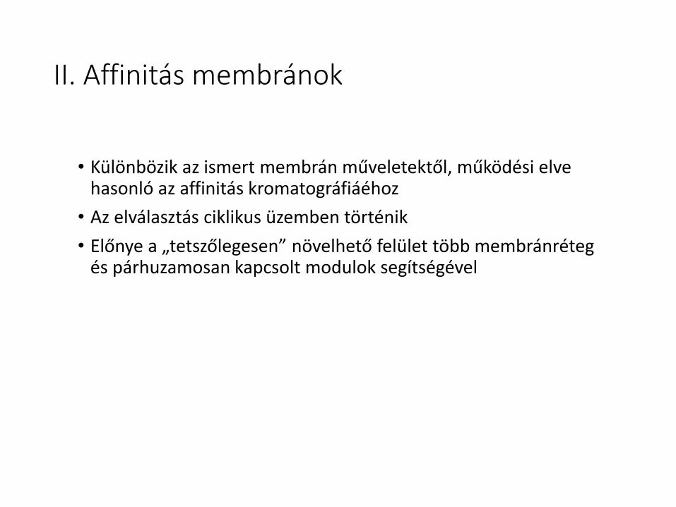
• Különbözik az ismert membrán műveletektől, működési elve hasonló az affinitás kromatográfiáéhoz
• Az elválasztás ciklikus üzemben történik
• Előnye a „tetszőlegesen” növelhető felület több membránréteg és párhuzamosan kapcsolt modulok segítségével
Affinitás membránok
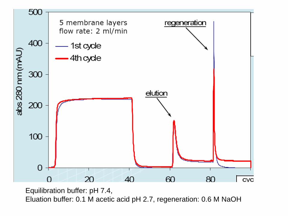
Equilibration buffer: pH 7.4,
Eluation buffer: 0.1 M acetic acid pH 2.7, regeneration: 0.6 M NaOH
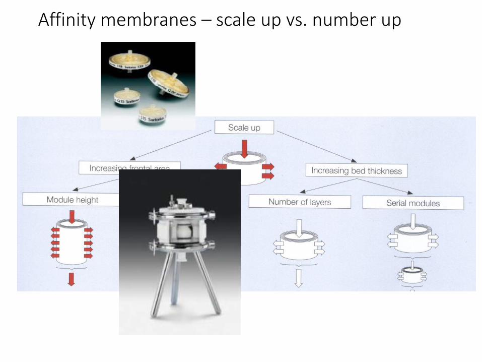
Affinity membranes – scale up vs. number up
Don’t forget
•Start to work on your own task: contact your supervisor!
•Next week: biomass valorization lecture
Thank you for your attention!
52
Recommended


![DEVELOPMENT OF A NEW ANALYTICAL METHOD AND …separation.[1] Chromatography may be preparative or analytical. The purpose of preparative chromatography is to separate the components](https://img.pdfslide.net/doc/110x75/602a77098265293b5777f41e/development-of-a-new-analytical-method-and-separation1-chromatography-may-be.jpg)


