Disclosure to Promote the Right To Information
Whereas the Parliament of India has set out to provide a practical regime of right to information for citizens to secure access to information under the control of public authorities, in order to promote transparency and accountability in the working of every public authority, and whereas the attached publication of the Bureau of Indian Standards is of particular interest to the public, particularly disadvantaged communities and those engaged in the pursuit of education and knowledge, the attached public safety standard is made available to promote the timely dissemination of this information in an accurate manner to the public.
इंटरनेट मानक
“!ान $ एक न' भारत का +नम-ण”Satyanarayan Gangaram Pitroda
“Invent a New India Using Knowledge”
“प0रा1 को छोड न' 5 तरफ”Jawaharlal Nehru
“Step Out From the Old to the New”
“जान1 का अ+धकार, जी1 का अ+धकार”Mazdoor Kisan Shakti Sangathan
“The Right to Information, The Right to Live”
“!ान एक ऐसा खजाना > जो कभी च0राया नहB जा सकता है”Bhartṛhari—Nītiśatakam
“Knowledge is such a treasure which cannot be stolen”
“Invent a New India Using Knowledge”
है”ह”ह
IS 12032-2 (1987): Graphical symbols for diagrams in thefield of electrotechnology, Part 2: Symbols elements,qualifying symbols and other symbols having generalapplication [ETD 1: Basic Electrotechnical Standards]


I-\
I : \_’
IS: 12032 ( Part 2 ) - 1987
IEC Pub 617-2 ( 1983 )
Indian Standard
GRAPHICAL SYMBOLS FOR DIAGRAMS IN THE FIELD OF
ELECTROTECHNOLOGY PART 2 SYMBOL ELEMENTS, QUALIFYING SYMBOLS AND OTHER SYMBOLS
HAVING GENERAL APPLICATION
_.-_ [ JEC Title : Graphical Symbols for Diagrams - Part 2 : Symbol Elements, Qualifying Symbols and Other Symbols Having General Application ]
UDC 621-3-061 : 003.62
@ Copyright 1988
/ *-\ I BUREAU OF INDIAN STANDARDS
\ / -4 MANAK BHAVAN, 9 BAHADUR SHAH ZAFAR MARG
NEW DELHI 110002
Gr 9 JVovcmber 1988

IS : 12032 ( Part 2 ) - 1987 UDC 621.3461 : 003.62 IEC Pub 617-2 ( 1983 )
Indian Standard
GRAPHICAL SYMBOLS FOR DIAGRAMS IN THE FIELD OF ELECTROTECHNOLOGY
PART 2 SYMBOL ELEMENTS, QUALIFYING SYMBOLS AND OTHER SYMBOLS
HAVING GENERAL APPLICATION
( IEC Title : Graphical Symbols for Diagrams - Part 2 : Symbol Elements, Qualifying Symbols and Other Symbols Having General Application )
National Foreword
This Indian Standard ( Part 2 ) which is identical with IEC Pub 617-2 ( 1983 ) ‘Graphical ;ymbols for diagrams - Part 2 : Symbol elements, qualifying symbols and other symbols having zenera application’, issued by the International Electrotechnical Commission ( IEC ), was adopted 3y the Bureau of Indian Standards on the recommendation of the Basic Electrotechnical Standards Sectional Committee and approval of the Electrotechnical Division Council.
Cross Reference
International Standard Corresponding Indian Standard
IEC Pub 445( 1973 ) Identification of apparatus IS : 11353-1986 Guide for uniform system terminals and general rules for a uniform of marking and identification of con- system of terminal marking, using an alpha- ductors and apparatus terminals riumeric notation
IS0 128-1982 Technical drawings - General principles of presentation
IS : 10714-1983 General principles of presentation on technical drawings ( Technically equivalent )
IEC Pub 27 Letter symbols to be used in electri- cal technology
IEC Pub 375( 1972 ) Conventions concerning electric and magnetic circuits
IEC Pub 617-6( 1983 ) Graphical symbols for diagrams - Part 6 Production and conver- sion of electrical euergy
IS : 3722 Letter symbols and signs used in electrical technology ( in 2 Parts )
IS : 9499- 1980 Conventions concerning electric and magnetic circuits
IS : 12032 ( Part 6 )-1987 Graphical sym- bols for diagrams in the field of electro- technology: Part 6 Production and conversion of electrical energy
The Basic Electrotechnical Standards Sect&al Committee has reviewed the provisions of the bllowing IEC -Publications and has decided that they are acceptable for use in conjunction with his standard:
IEC Pub 364-3 ( 1977 ) Electrical Installations of buildings; Part 3 Assessment of general characteristics
IEC Pub 617-10 ( 1983 ) Graphical syrnbols for diagrams; Part 10 Telecommunications: Transmission
IEC Pub 617-12 ( 1983 ) Graphical symbols for diagrams; Part 12 Binary logic elements
IEC Pub 617-13 ( 1978 ) Graphical symbols for diagrams; Part 13 Analogue elements
Adopted 18 June 1987 Q November 1988, BIS I
BUREAU OF INDIAN STANDARDS
MANAK BHAVAN, 9 BAHADUR SHAH ZAFAR MARG
NEW DELHI 110002
Gr 9

As in the Original Standard, this Page is Intentionally Left Blank
IS : 12032 (Part 2)-1987 IEC Pub 617-2 (1983)
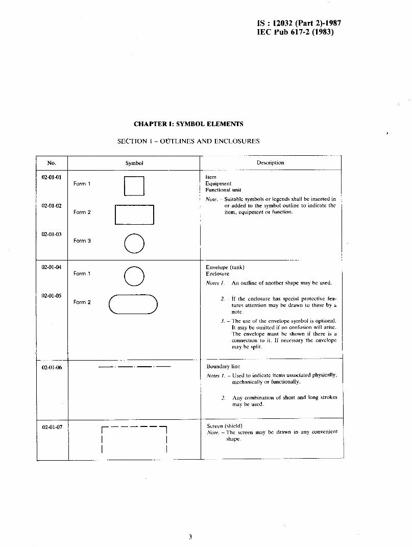
CHAPTER I: SYMBOL ELEMENTS
SECTION I- OfJTLINES AND ENCLOSURES
No.
02-01-01 Form 1
Symbol
cl
Item Equipment Functional unit
Description
Note. - Suitable symbols or legends shall be inserted in 02-Ol-cr2
Form 2
I
or added to the symbol outline to indicate the item, equipment or function.
02-01-03 Form 3 0
02-01-04 Envelope (tank) Form 1 0 Enclosure
Notes 1. - An outline of another shape may be used.
02-01-05 Form 2
2. - If the enclosure has special protective fea- tures attention may be drawn to these by a note.
3. - The use of the envelope symbol is optional. It may be omitted if no confusion will arise. The envelope must be shown if there is a connection to it. If necessary the envelope may be split.
02-01-06 Boundary line
Notes I. - Used to indicate items associated physically, mechanically or functionally.
2. - Any combination of short and long strokes may be used.
02-01-07 r -----
1 Screen (shield) Note. -The screen may be drawn in any convenient
I I shape.
I I
,

IS : 12032 (Part 2)-1987 IEC Pub 617-2 (1983)
CHAPTER II: QUALIFYING SYMBOLS
SECTION 2 - KIND OF CURRENT AND VOLTAGE
'L 50 Hz
'L 100...600 kHz
3N'L 50Hz 400/23QV
NO. Symbol -
Description
Form 1 Direct current
Notes I. - The voltage may be indicated at the right of the symbol and the type of system at the left.
02-02-02 2M- 220/11ov Example:
Direct current, three conductors including mid-wire, 220 V (110 V between each outer conductor and mid- wire)
2M may be replaced by 2 + M
02-02-03 Form 2 2. - Symbol 02-02-03 is to be used if symbol 02-02-01 causes confusion.
-
02-02-04 Alternating current
Notes I. - The numerical value of the frequency or the trequency range may be added at the right- hand side of the symbol.
02-02-0s Exampies:
Alternating current of SO Hz
02-02-06 Alternating current frequency range 100 kHz to 600 kHz
2. - The voltage may also be indicated to the right of the symbol.
3. - The number of phases and the presence of a neutral may be indicated at the left-hand side of the symbol.
02-02-07 Example.
A1ternatir.g current: thre< phase ‘r\:tn ~rcuriai, 50 Hr, 400 V (230 V between phase and neutral). 3N may be replaced by ? + N
4. - If It is necessary to indicate a system m ac- cordance with the designations established in IEC Publication 364-3: Electrical Installa- tions of Buildings, Part 3: Assessment of General Characteristics, the corresponding designation should be added to the symbol.
02-02-08 Example:
Alternating current, three-phase, 50 Hz; system having one point directly earthed and separate neutral and pro- tective conductqrs throughout
R
4

IS :. 12032 (Part 2)-1987 IEC Pub 617-2 (1983)
No. ’
02-02-09
M-02-10
02-M-11
Symbol Description
Alternating current, different frequency ranges
The following symbols may be used when it is necessary
on a given drawing to distinguish between the different
frequency ranges
Relatively low frequencies (example: power frequencies
or sub-audio frequencies)
Medium frequencies (example: audio)
Relatively high frequencies (example: super audio,
carrier and radio frequencies)
02-02-12 Rectified current with alternating component (if it is
necessary to distinguish from a steady-direct current)
02-02-13
02-02-14
02-02-15
+
N
Positive polarity
Negative polarity
--
Neutral
Note. - This symbol for neutral is given in I EC Publica-
tion 445: Identification of Apparatus Terminals
and General Rules for a Uniform System of
Terminal Marking, Using an Alphanumeric
Notation.
02-02-16 M Mid-wire
No/e. - This symbol for mid-wire is given in I EC Publi-
catton 445.
5

IS : 12032 (Part 2)-1987 IEC Pub 617-2 (1983)
SECTION 3 - VARIABILITY
3.1 Variability is non-inherent when the variable quantity is controlled by an external device, for example, when the resistance is controlled by a regulator.
3.2 Variability is inherent when the variable quantity depends on qualities of the device itself, for example, when the resistance changes with change of voltage or with change of temperature.
3.3 The sign for variability should be drawn across the main symbol at about 45” to the centre line of the symbol.
_
No.
02-03-01
Symbol Description
Variability, non-inherent
02-03-02 Variability. non-Inherent,
non-linear
02-03-03
/
_.-_.
I - ____
Variability, inherent
Nore. - Information on the controlling quantity, for
example voltage or temperature, may he shown
near the symbol.
02-03-04 Variability, inherent, non-linear
The note with symbol 02-03-03 applies.
02-03-05
02-03-M
Pre-set adjustment permitted only at zero current
6

IS : 12032 (Part 2)-1987 IEC Pub 617-2 (1983)
NO
02-03-07
02-oi-ox
_._-_
02-03-09
02-03-10
02-w I 1
02-0.1. I2
Symbol
/
/‘ /
J
Description
Variability in steps Stepping action
Note. - A figure indicating the number of steps may be added.
Example:
Variability, non-inherent in five steps
Continuous variability
Example:
Preset adjustment, continuously variable
Automatic (inherent) control
Note. -The controlled quantity may be indicated adjacent to the symbol.
Example:
Amplifier with automatic gain control
7

IS : 12032 (Part 2)-1987 IEC Pub 617-2 (1983)
SECTION 4 - DIRECTION OF FORCE OK MOTION
4.1 An arrow may be used to indicate the direction in which the movable
part of ;I symbol must move to give a required effect (see the example of
symbol 02-04-02).
It may also indicate the direction of a force or the direction of motion
of the physical part symbolized. In such cases a note to indicate the view
point may be required.
4.2 The effect caused by movement may be explained by symbols or by
a text.
No. Symbol Dc\crlption
02-04-01 * Kcct~l~near force or motion III the direction of the arrow
02-04-02 4 W Bidlrccticlnal rectilinear force or motion
E.rurn/,lc
Frequency is incrcascd when wiper 3 is moved towards terminal ?
02-04-03
02-04-04
_
02-04-05
07-04-06
Frequency
decreases t) increases
7-S
4-L ~-
Unidirecuonal rotation in the dnection of the arrow. for example clockwise /
Bidirectional rotation
Bidirectional rotation, limited in both dlrections
_~~~_~~_____.
Reciprocating moticn

I§ : 12032 (Part 2)-1987 IEC Pub 617-2 (1983)
SECTION 5 - DIRECTION OF FLOW
___.
No.
02-05-01
Symbol
\ /
Description
Propagation. energy flow, sgnal flow, one way
02-05-02 \ / H \ Propagation, both ways, simultaneously Simultaneous transmission and reception
02-05-03 /. . / Propagation, both ways, not simultaneously Alternate transmission and reception
02-05-04 / _ \ Transmission
Note. - The dot may be omitted if the sense is unam- biguously given by the arrowhead in combina- tion with the symbol to which it is applied. For example see symbol 10-06-04.
02-05-0s \ _ 7 - Reception
Note. - The dot may be omitted if the sense is unam- biguously given by the arrowhead in combina- tion with the symbol to which it is applied. For example see symbol 10-06-03.
02-05-06 t : Energy flow from the busbars
02-05-07 t : Energy flow towards the busbars
02-05-08 I :: Bidirectional energy flow
9

IS : 12032 (Part 2)-1987 IEC Pub 617-2 (1983)
SECTION 6 - OPERATIONAL DEPENDENCE
CHARACf’ERISTIC QUANTITY ON A
a24ba2 <
Description -
Operating when the characteristic quantity is higher
than the setting value
Operating when the characteristic quantity is lower than
the setting value
Operating when the characteristic quantity is either
higher than a given high setting ot lower than a given
low setting
Operating when value of the characteristic quantity
becomes zero
____- -__-
Operating when the value of the characteristic quantity
differs from zero by an amount which is very small com-
pared with the normal value

IS : 12032 (Part 2)-1987 IEC Pub 617-2 (1983)
SECTION 7 - TYPES OF MATERIAL
7.1 The type of material may be indicated either by using its chemical sym- bol, or by one of the qualifying symbols given below. These symbols have been drawn in rectangles, but the rectangle may be omitted when they are used in conjunction with another symbol. If necessary, use may be made of the symbols for materials given in IS0 128: Engineering drawing - Principles of presentation. ~_~__.___~_ --
No. SYtllbOi
p :A Description
___ --~-
02-07-01 Material, unspecified
-___.
02-07 -02 Material, solid
.--__ _-_-.-- ------
02-07-03 I--1
Material, liquid
_~____._..
M-M-04 P
Material, gas
-__ ___.-__I~ -.
m-07-05 LZCI
Material, electret
-._._-I--~- --
02-07-06 I
Material, semicondticting
___ ____ ____-____-P-
02-07-07 Material. insulating
_~-
II

IS : 12032 (Part 2)-1987 IEC Pub 617-2 (1983)
SECTION 8 - EFFECT OR DEPENDENCE
No.
02-u&01
Symbol
FJ
Thermal effect
Description
--
02-0a-02
>
Electromagnetic effect
02-08-03
02-08-04
02-08-05
z Magnetostrictive effect
_
X Magnetic field effect or dependence
I i Delay
-~- ..--- _i
‘
12

No.
m-09-01
02-09-02
--Y--
02-W-03
IS : 12032 (Part 2)-1987 IEC Pub 617-2 (1983)
SECTION 9 - RADIATION
9.1 Arrows pointing towards a symbol denote that the device symbolized will respond to incident radiation of the indicated type.
9.2 Arrows pointing away from a symbol denote the etiission of the indi- cated type of radiation by the device symbolized.
9.3 Arrows located within a symbol denote a self-contained radiation source.
Symbol Description
Radiation, non-ionizing, electromagnetic (for example radio waves or visible light)
Coherent radiation, non-ionizing (for example cohere& light)
Radiation, ionizing
Note. - If it is necessary to show the specific type of ionizing radiation, the symbol may be aug- mented by the addition of s\mhols or letters such as the following:
a = alpha particle 0 = beta particle y = gamma rays b = deuteron e = proton 11 = neutron n = pion x = K meson 11 -= muon X= X-rag’
13

IS : 12032 (Part 2)-1987 IEC Pub 617-2 (1983)
SECTION 10 - SIGNAL WAVEFORMS
10.1 Each symbol represents an idealized shape of the waveform.
--___ No. Symbol Description
____. _---.__ -_
02-10-01 n
JvL 3,
Positive-going pulse
__~
02-10-02 u
Negative-going pulse
__- --~
02-10-03 Pulse of alternating current
---. ~~_~__
02-10-04
_r
Positive-going step function
_-
02-10-05
-l
Negative-going step function
___- __-_
u2-lo-06 Saw-tooth
.-_._ __
SECTION 11 - PRINTING, PERFORATING AND FACSIM1I.E
1 No. 1 Symbol Description
c Tape printing
__-.
Tape perforating or using perforated tape
,
14

IS : 12032 (Part 2)-1987 IEC Pub 617-2 (1983)
NO.
02-12-01 Form 1 _-----
02-12-02 ------
02-12-03
M-12-04
____.
02-12-05
02-12-06
--- -- >
Form 2 --
Form 1
Forrn 2
02-12-07
02-12-08
02-12-W
02-12-10
__--
02-12-11
M-12-12
M-12-13
--
02-12-14
02-12-15
CHAPTER 111: OTHER SYMBOLS HAVING GENERAL APPLICATION
SECTION 12 - MECHANICAL CONTROLS
Symbol
--++__
---v--
l --v----
l --- -v- --.. -- -- -8-
__@!___._
I --- L_
-- n-_
__‘n__
.- Description
Mechanical connection (link)
Pneumatic connection (link)
Hydraulic connection (link)
Exumples:
Mechanical connection with indication of direction of
force or motion
Mechanical connection with indication of direction of
rotation.
Noles 1. - The arrow is assumed to be placed in front of
the connection symbol.
2. - Symbol 02-12-W is to be used if the space is
too restricted to permit the use of symbol
02-12-01.
Delayed action
Note. - Delayed action in the direction of movement
from the arc towards its centre.
Automatic return
Note. - The triangle is pointed in the return direction.
Detent
Non-automatic return
Device for maintaining a given position
Detent, disengaged
_~_____
Detent, engaged
Mechanical interlock between two devices
Latching device, disengaged
Latching device, engaged
Blocking device
Blocking device engdg’ed. movement to the left is
blocked
i5

IS : 12032 (Part 2)-1987 IEC Pub 617-2 (1983)
NO.
02-12-16
02-12-17
Symbol
--J L__
___JIi-L_
Desaiption
Clutch Mechanical coupling
_
Mechanical coupling, disengaged
02-12-18
02-12-19
_-A-L_ Mechanical coupling, engaged
_LHL_ ? 3
Example:
Unidirectional coupling device for rotation
Free wheel
02-12-20
02-12-21
02-12-22 -----
Brake
Examples:
Electric motor with brake applied.
Electric motor with brake released.
02-12-23 Gearing
16

IS : 12032 (Part 2)-1987 IEC Pub 617-2 (1983)
SECTION 13 - OPERATING DEVICES AND METHODS
Symbol
----
Description
Manually operated control, general case
-___
Manually operated control with restricted access
Operated by pulling
---- Operated by turning
Operated by pushing
Operated by proximity effect
---- Emergency awtch (mushroom-head safety feature)
Operated by pedal
02-13-P! Operated by lever
02-13-12
.-
02-13-13
Operated by removable handle
Operated hy key
02-13-14
02-13-15
--. ______
_-__ Operated by crdnk
Q- ---- Operated by roller
17

IS : 12032 (Part 2)-1987 IEC Pub 617-2 (1983)
No.
02-13-16
Symbol
6
A--
Description ~~
Operated by cam
Now If desired. a more detailed drawing of the cam may be shown. This applies Aso to a profile
plate.
02-13-17
CI
Exumplev.
Cam profile
02-13-18
02-13-19
Profile plate
Cam profile (developed representation)
G
Operated by cam and roller
--
02-13-20
I
Operated by stored mechanical energy ---
Now Information showing the form of stored energy
may be added in the square.
02-13-21
E
Operated by pneumatic or hydraulic control, single
-- acting
02-13-22
02-13-23
6s --
0-
--
Operated by pneumatic or hydraulic control, double
acting
Operated by electromagnetic actuator
02-13-24
>
Operated by electromagnetic overcurrent protection ---
02-13-25
+
Operated by thermal actuator, for example thermal ---
relay, thermal overcurrent protection
02-13-26
0
Operated by electric motor
M ---
02-13-27 Operated by electric clock
-
,
18
IS : 12032 (Part 2)-1987 IEC Pub 617-2 (1983)
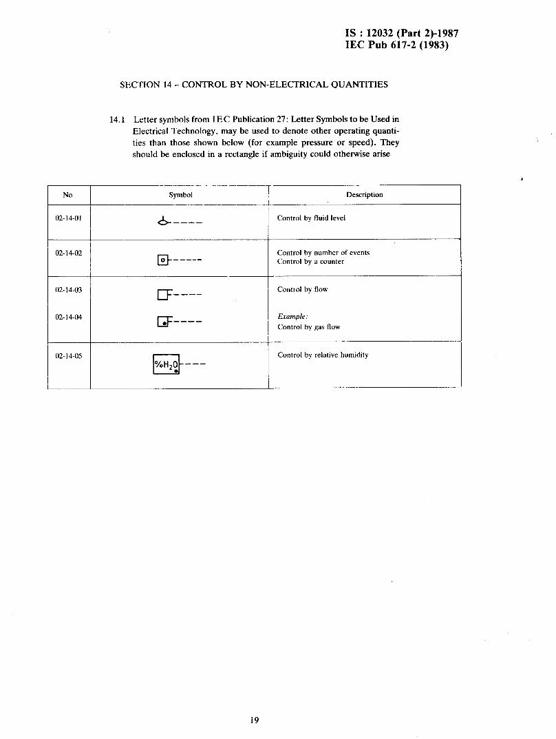
SECTION 14 - CONTROL BY NON-ELECTRICAL QUANTITIES
14.1 Letter symbols from IEC Publication 27: Letter Symbols to be Used in Electrical Technology, may be used to denote other operating quanti- ties than those shown below (for example pressure or speed). They should be enclosed in a rectangle if ambiguity could otherwise arise
No
02-14-01
Symbol
CL ----
Description
Control by fluid level
02-14-02 B---__
Control by number of events Control by a counter
02-14-03
02-14-04,
02-14-05
IIF Control by flow - ---
p---- Example:
Control by gas flow
______
Control by relative humidity
-
19

IS : 12032 (Part 2)-1987 IEC Pub 617-2 (1983)
SECTION 15 - EARTH AND FRAME CONNECTIONS, EQUIPOTENTIALITY
No.
02-15-01
Symhol
A_ - -
Description
Earth, general symbol Ground, general symbol
Note. - Supplementary information may be given to de- fine the status or the puroose of the earth if this is not readily apparent.
02-15-02
m -
Noiseless earth Noiseless ground
02-15-03
0 - -
Protective earth Protective ground
Nov. -This symbol may he used in place of symbol 02-15-01 to indicate an earth connection having a specified protective function, for example for protection against electrical shock in case of a fault.
02-15-04
A7
Frame Chassis
______
Note. - The hatching may he completely or partly omit- ted if there is no ambiguity. If tb- hatching is omitted, the line representing the frame or chassis shall be thicker as shown below:
02-15-05 Equipotentiality
20

IS : 12032 (Part 2)-1987 IEC Pub 617-2 (1983)
NO.
02- 16-01
02- 16-02
02-16-03,
SECTION 16 - IDEAL CIRCUIT ELEMENTS
lb.1 Additional indications may be added to the symbols 02-lh-01 to 02-16-03 according to I EC Publication 375: Conventions Concerning Electric and Magnetic Circuits.
Symbol
$ -
Description
Ideal current source
ideal voltage source
_~
Ideal gyrator
21
IS : 12032 (Part %)-I987 IEC Pub 617-2 (1983)
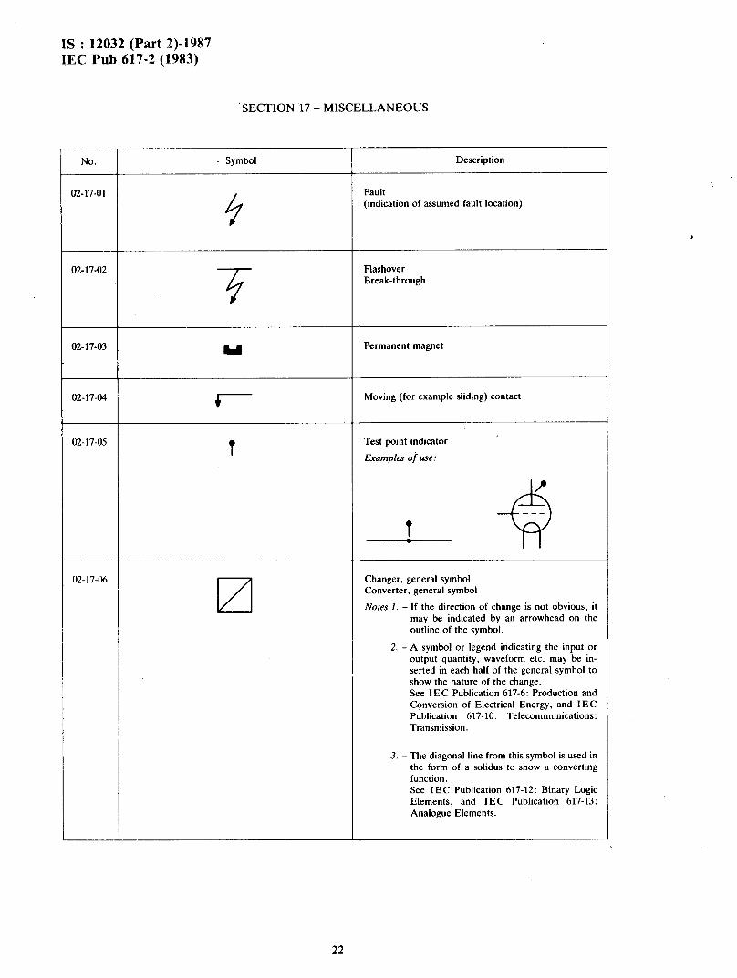
SECTION 17 - MISCELLANEOUS
_.
No. - Symbol Description
02-17-01
9
Fault (indication of assumed fault location)
02-17-02
-..
Flashover Break-through
02-17-03 u Permanent magnet
02-17-04 Moving (for example sliding) contact
M-17-05 t
Test point indicator
Examples of use:
02-17-06
q Changer, general symbol
Converter, general symbol
Notes 1. - If the direction of change is not obvious, it may be indicated by an arrowhead on the outline of the symbol.
2. - A symbol or legend indicating the input or output quantity, waveform etc. may be in- serted in each half of the general symbol to show the nature of the change. See I EC Publication 617-6: Production and Conversion of Electrical Energy, and IEC Publication 617-10: Telecommunications: Transmission.
3. - The diagonal line from this symbol is used in the form of a solidus to show a converting function. See IEC Publication 617-12: Binary Logic Elements, and IEC Publication 617-13: Analogue Elements.
22

IS : 12032 (Part 2)-1987 IEC Pub 617-2 (1983)
No.
02- 17-07
Symbol ~ _..__, _
X//Y
Ll
-.--~
Description
Galvanic separator
Nore. - If necessary, indication of the way of separation
may be given below the qualifying symbol.
for example: X//Y
11
Galvanic separation by opto-coupler
K- 17-08 n Identifier of analogue signals
Nore. - The symbol shall be used only when it is neces-
sary to distinguish between analogue and digital
signals.
-~-
W- 17-09 tar
-
Identifier of digital signals
The note with symbol M-17-08 applies.
Nope. - A time-sequenced number (m) of bits may be
denoted m 0.
____- --
L
23

IS : 12032 (Part 2)-1987 IEC Pub 617-2 (1983)
APPEND& A: OLDER SYMBOLS
SECTION Al - OPERATING DEVICE
Al.1 This symbol will be required for a change-over period, but should be superseded as soon as practicable by the symbol 02-13-23.
Operated by electromagnetic actuator
24

BUREAU OF INDIAN STANDARDS
Headquarters:
Manak Bhavan, 9 Bahador Shah Zafar Marg, NEW DELHI 110002
Telephones : 3 31 01 31 3 31 13 75
Regional Offices:
Central : Manak Bhavan, 9 Bahadur Shah Zafar Marg, NEW DELHI 110002
Telegrams : Manaksanstha ( Common to all Offices )
Telephone
3 31 01 31, 3 31 13 75
*Eastern : 1 /I 4 C. I. T. Scheme VII M, V. I. P. Road, Maniktola, CALCUTTA 700054
Northern : SC0 445-446, Sector 36-C, CHANDIGARH 160036
36 24 99
2 18 43, 3 16 41
Southern : C. I. T. Campus, MADRAS 600113
TWestern : Manakalaya, ES MIDC, Marol, Andheri ( East ), BOMBAY 400093
41 2442, 41 2619, 41 2916
6 32 92 96
Branch Offices:
‘Pushpak’, Nurmohamed Shaikh Marg, Khanpur, AHMADABAD 380001
Peenya Industrial Area, 1 st Stage, Bangalore-Tumkur Road BANGALORE 560058
Gangotri Complex, 6th Floor, Bhadbhada Road, T. T. Nagar, BHOPAL 462003
Plot No. 82183. Lewis Road, BHUBANESHWAR 751002
63/5 Ward No. 29, R. G. Barua Road, 6th By-lane, GUWAHATI 781003
2 63 48, 2 63 49
38 49 65, 38 49 56
66716
5 36 27
-
5-8-56C L. N. Gupta Marg ( Nampally Station Road ), 23 10 83 HYDERABAD 500001
RI 4 Yudhister Marg, C Scheme, JAIPUR 302006 6 3471, 69832
1 l7/418 B Sarvodaya Nagar, KANPUR 208005 21 68 76, 21 82 92
Patliputra Industrial Estate, PATNA 800013 6 23 06
T.C. No. 14/1421, University P.O. Palayam, TRIVANDRUM 696036 6 21 04, 6 21 17
Inspection Offices ( With Sale Point ):
Pushpanjali, First Floor, 205-A West High Court Road, Shankar Nagar Square, NAGBUR 440010
Institution of Engineers ( India ) Building, 1332 Shivaji Nagar, PUNE 411006
*Sales Office in Calcutta is at 5 Chowringhes Approach, P.O. Princep Street, CALCUTTA 700072
tSales Office in Bombay is at Novelty Chambers, Grant Road, BOMBAY 400007
2 51 71
5 24 36
27 68 00
89 65 28
Printed at Printograph, New Delhi, India
Recommended