International Journal for Research in Engineering Application & Management (IJREAM)
ISSN : 2454-9150 Vol-05, Issue-12, Mar 2020
24 | IJREAMV05I1260010 DOI : 10.35291/2454-9150.2020.0162 © 2020, IJREAM All Rights Reserved.
Gas Metal Arc Welding Sequence Effect on
Residual Stress and Distortion by using Finite
Element Analysis Harika Prabandapu*,
S.R.Somayajulu
Department of Mechanical and Engineering, VNRJIET Hyderabad, India.
[email protected]*, [email protected]
Abstract: It is a well-known fact that fusion welding is being extensively used in a wide spectrum of fabrication
industries. In spite of its being a versatile joining process of materials of any thickness, it suffers from some serious
setbacks which impair the life of weldments in service. Of utmost concern are the evolution of inevitable residual
stresses and distortion in weldments which are the direct result of complex non-uniform thermal cycles experienced
during fusion welding. Over the past few decades, finite element method has gained ground as a well-established
method to numerically analyze welding related problems. Numerical simulation based on finite element modeling is
used to study the influence of welding sequences on the distribution of residual stress and distortion generated when
welding a flat-bar stiffener to a steel plate. The simulation consists of sequentially coupled thermal and structural
analyses. In Transient thermal analysis, time-dependent temperature distribution is determined. Temperatures from
thermal analysis are applied as loads in a structural analysis yielding the three-dimensional residual stress and
distortion fields. The effect of four welding sequences on the magnitude of residual stress and distortion in the plate is
investigated.
Keywords — Numerical Simulation, residual stresses and distortion, transient thermal analysis, thermal and structural
analysis
I. INTRODUCTION
1.1 General Introduction
Welding is the most prominent process for joining large
components into complex assemblies or structures. A
necessary condition for welding is that the two or more
surfaces to be joined must be brought into intimate contact.
When fusion takes place, the joint is achieved by melting of
two or more work piece materials in a localized region. In
contrast, the solid-state joining processes rely on plastic
deformation of the surface asperities along the contact
surface representing the original weld interface or the
impending weld joint.
Arc welding is the most commonly used process in almost
all manufacturing sectors ranging from small to large size
fabrication industries, to strategic sectors such as aerospace,
ship building etc. This is due to the fact that arc welding
process is considered to be the most versatile joining
method to ensure structural integrity in the steel joints. It is
capable of joining materials of all thicknesses. A welding
power supply is used to create and maintain an electric arc
between an electrode and the base material to melt metals at
the welding point. In such welding processes the power
supply could be AC or DC, the electrode could be
consumable or non-consumable and a filler material may or
may not be added. The most common types of arc welding
are:
Shielded Metal Arc Welding (SMAW): A process that uses
a coated consumable electrode to lay the weld. As the
electrode melts, the (flux) coating disintegrates, giving off
shielding gases that protect the weld area from atmospheric
gases and provides molten slag which covers the filler metal
as it travels from the electrode to the weld pool. Once part
of the weld pool, the slag floats to the surface and protects
the weld from contamination as it solidifies. Once hardened,
the slag must be chipped away to reveal the finished weld.
Gas Metal Arc Welding (GMAW): A process in which a
continuous and consumable wire electrode and a shielding
gas (usually an argon and carbon dioxide mixture) are fed
through a welding gun.
Gas Tungsten Arc Welding (GTAW): A process that uses a
non-consumable tungsten electrode to produce the weld.
The weld area is protected from atmospheric contamination
by a shielding gas, and a filler metal that is fed manually is
usually used.
1.2 Gas Metal Arc Welding
The gas metal arc welding (GMAW) process has become a
popular method for joining components of steel structures
International Journal for Research in Engineering Application & Management (IJREAM)
ISSN : 2454-9150 Vol-05, Issue-12, Mar 2020
25 | IJREAMV05I1260010 DOI : 10.35291/2454-9150.2020.0162 © 2020, IJREAM All Rights Reserved.
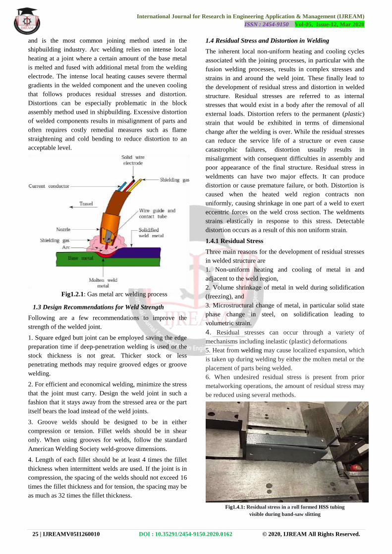
and is the most common joining method used in the
shipbuilding industry. Arc welding relies on intense local
heating at a joint where a certain amount of the base metal
is melted and fused with additional metal from the welding
electrode. The intense local heating causes severe thermal
gradients in the welded component and the uneven cooling
that follows produces residual stresses and distortion.
Distortions can be especially problematic in the block
assembly method used in shipbuilding. Excessive distortion
of welded components results in misalignment of parts and
often requires costly remedial measures such as flame
straightening and cold bending to reduce distortion to an
acceptable level.
Fig1.2.1: Gas metal arc welding process
1.3 Design Recommendations for Weld Strength
Following are a few recommendations to improve the
strength of the welded joint.
1. Square edged butt joint can be employed saving the edge
preparation time if deep-penetration welding is used or the
stock thickness is not great. Thicker stock or less
penetrating methods may require grooved edges or groove
welding.
2. For efficient and economical welding, minimize the stress
that the joint must carry. Design the weld joint in such a
fashion that it stays away from the stressed area or the part
itself bears the load instead of the weld joints.
3. Groove welds should be designed to be in either
compression or tension. Fillet welds should be in shear
only. When using grooves for welds, follow the standard
American Welding Society weld-groove dimensions.
4. Length of each fillet should be at least 4 times the fillet
thickness when intermittent welds are used. If the joint is in
compression, the spacing of the welds should not exceed 16
times the fillet thickness and for tension, the spacing may be
as much as 32 times the fillet thickness.
1.4 Residual Stress and Distortion in Welding
The inherent local non-uniform heating and cooling cycles
associated with the joining processes, in particular with the
fusion welding processes, results in complex stresses and
strains in and around the weld joint. These finally lead to
the development of residual stress and distortion in welded
structure. Residual stresses are referred to as internal
stresses that would exist in a body after the removal of all
external loads. Distortion refers to the permanent (plastic)
strain that would be exhibited in terms of dimensional
change after the welding is over. While the residual stresses
can reduce the service life of a structure or even cause
catastrophic failures, distortion usually results in
misalignment with consequent difficulties in assembly and
poor appearance of the final structure. Residual stress in
weldments can have two major effects. It can produce
distortion or cause premature failure, or both. Distortion is
caused when the heated weld region contracts non
uniformly, causing shrinkage in one part of a weld to exert
eccentric forces on the weld cross section. The weldments
strains elastically in response to this stress. Detectable
distortion occurs as a result of this non uniform strain.
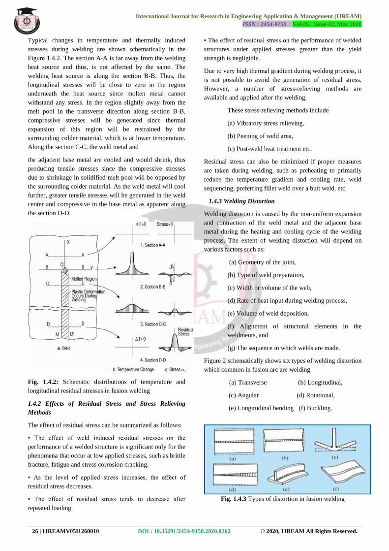
1.4.1 Residual Stress
Three main reasons for the development of residual stresses
in welded structure are
1. Non-uniform heating and cooling of metal in and
adjacent to the weld region,
2. Volume shrinkage of metal in weld during solidification
(freezing), and
3. Microstructural change of metal, in particular solid state
phase change in steel, on solidification leading to
volumetric strain.
4. Residual stresses can occur through a variety of
mechanisms including inelastic (plastic) deformations
5. Heat from welding may cause localized expansion, which
is taken up during welding by either the molten metal or the
placement of parts being welded.
6. When undesired residual stress is present from prior
metalworking operations, the amount of residual stress may
be reduced using several methods.
Fig1.4.1: Residual stress in a roll formed HSS tubing
visible during band-saw slitting
International Journal for Research in Engineering Application & Management (IJREAM)
ISSN : 2454-9150 Vol-05, Issue-12, Mar 2020
26 | IJREAMV05I1260010 DOI : 10.35291/2454-9150.2020.0162 © 2020, IJREAM All Rights Reserved.
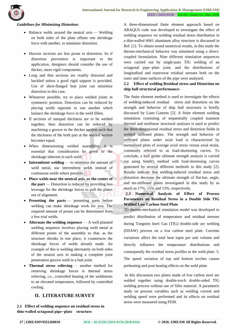
Typical changes in temperature and thermally induced
stresses during welding are shown schematically in the
Figure 1.4.2. The section A-A is far away from the welding
heat source and thus, is not affected by the same. The
welding heat source is along the section B-B. Thus, the
longitudinal stresses will be close to zero in the region
underneath the heat source since molten metal cannot
withstand any stress. In the region slightly away from the
melt pool in the transverse direction along section B-B,
compressive stresses will be generated since thermal
expansion of this region will be restrained by the
surrounding colder material, which is at lower temperature.
Along the section C-C, the weld metal and
the adjacent base metal are cooled and would shrink, thus
producing tensile stresses since the compressive stresses
due to shrinkage in solidified melt pool will be opposed by
the surrounding colder material. As the weld metal will cool
further, greater tensile stresses will be generated in the weld
center and compressive in the base metal as apparent along
the section D-D.
Fig. 1.4.2: Schematic distributions of temperature and
longitudinal residual stresses in fusion welding
1.4.2 Effects of Residual Stress and Stress Relieving
Methods
The effect of residual stress can be summarized as follows:
• The effect of weld induced residual stresses on the
performance of a welded structure is significant only for the
phenomena that occur at low applied stresses, such as brittle
fracture, fatigue and stress corrosion cracking.
• As the level of applied stress increases, the effect of
residual stress decreases.
• The effect of residual stress tends to decrease after
repeated loading.
• The effect of residual stress on the performance of welded
structures under applied stresses greater than the yield
strength is negligible.
Due to very high thermal gradient during welding process, it
is not possible to avoid the generation of residual stress.
However, a number of stress-relieving methods are
available and applied after the welding.
These stress-relieving methods include
(a) Vibratory stress relieving,
(b) Peening of weld area,
(c) Post-weld heat treatment etc.
Residual stress can also be minimized if proper measures
are taken during welding, such as preheating to primarily
reduce the temperature gradient and cooling rate, weld
sequencing, preferring fillet weld over a butt weld, etc.
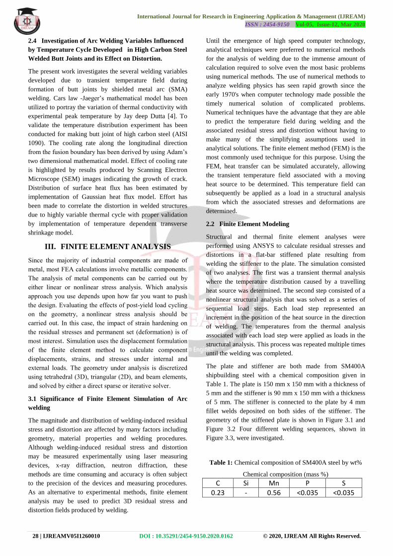
1.4.3 Welding Distortion
Welding distortion is caused by the non-uniform expansion
and contraction of the weld metal and the adjacent base
metal during the heating and cooling cycle of the welding
process. The extent of welding distortion will depend on
various factors such as:
(a) Geometry of the joint,
(b) Type of weld preparation,
(c) Width or volume of the web,
(d) Rate of heat input during welding process,
(e) Volume of weld deposition,
(f) Alignment of structural elements in the
weldments, and
(g) The sequence in which welds are made.
Figure 2 schematically shows six types of welding distortion
which common in fusion arc are welding –
(a) Transverse (b) Longitudinal,
(c) Angular (d) Rotational,
(e) Longitudinal bending (f) Buckling.
Fig. 1.4.3 Types of distortion in fusion welding
International Journal for Research in Engineering Application & Management (IJREAM)
ISSN : 2454-9150 Vol-05, Issue-12, Mar 2020
27 | IJREAMV05I1260010 DOI : 10.35291/2454-9150.2020.0162 © 2020, IJREAM All Rights Reserved.
Guidelines for Minimizing Distortion:
Balance welds around the neutral axis — Welding
on both sides of the plate offsets one shrinkage
force with another, to minimize distortion.
Heavier sections are less prone to distortion. So if
distortion prevention is important to the
application, designers should consider the use of
thicker, more rigid components.
Long and thin sections are readily distorted and
buckled unless a good rigid support is provided.
Use of short-flanged butt joint can minimize
distortion in this case.
Whenever possible, try to place welded joints in
symmetric position. Distortion can be reduced by
placing welds opposite to one another which
balance the shrinkage force in the weld fillets.
If sections of unequal thickness are to be welded
together, then distortion can be reduced by
machining a groove in the thicker section such that
the thickness of the both part at the welded section
becomes equal.
When dimensioning welded assemblies, it is
essential that consideration be given to the
shrinkage inherent in each weld.
Intermittent welding — to minimize the amount of
weld metal, use intermittent welds instead of
continuous welds where possible.
Place welds near the neutral axis, or the center of
the part — Distortion is reduced by providing less
leverage for the shrinkage forces to pull the plates
out of alignment.
Presetting the parts — presetting parts before
welding can make shrinkage work for you. The
required amount of preset can be determined from
a few trial welds.
Alternate the welding sequence — A well-planned
welding sequence involves placing weld metal at
different points of the assembly so that, as the
structure shrinks in one place, it counteracts the
shrinkage forces of welds already made. An
example of this is welding alternately on both sides
of the neutral axis in making a complete joint
penetration groove weld in a butt joint.
Thermal stress relieving — another method for
removing shrinkage forces is thermal stress
relieving, i.e., controlled heating of the weldments
to an elevated temperature, followed by controlled
cooling.
II. LITERATURE SURVEY
2.1 Effect of welding sequence on residual stress in
thin-walled octagonal pipe−plate structure
A three-dimensional finite element approach based on
ABAQUS code was developed to investigate the effect of
welding sequence on welding residual stress distribution in
a thin-walled 6061 aluminum alloy structure is discussed in
Ref. [1]. To obtain sound numerical results, in this study the
thermo-mechanical behavior was simulated using a direct-
coupled formulation. Nine different simulation sequences
were carried out by single-pass TIG welding of an
octagonal pipe−plate joint, and the distributions of
longitudinal and transverse residual stresses both on the
outer and inner surfaces of the pipe were analyzed.
2.2 Effect of welding Residual stress and Distortion on
ship hull structural performance-
The finite element method is used to investigate the effects
of welding-induced residual stress and distortion on the
strength and behavior of ship hull structures is briefly
discussed by Liam Gannon [2]. A finite element welding
simulation consisting of sequentially coupled transient
thermal and nonlinear structural analyses is used to predict
the three-dimensional residual stress and distortion fields in
welded stiffened plates. The strength and behavior of
stiffened plates under axial load is characterized by
normalized plots of average axial stress versus axial strain,
commonly referred to as load-shortening curves. To
conclude, a hull girder ultimate strength analysis is carried
out using Smith's method with load-shortening curves
generated by several different methods in this study [2].
Results indicate that welding-induced residual stress and
distortion decrease the ultimate strength of flat-bar, angle,
and tee-stiffened plates investigated in this study by as
much as 17%, 15% and 13%, respectively.
2.3 Numerical Analysis of Effect of Process
Parameters on Residual Stress in a Double Side TIG
Welded Low Carbon Steel Plate
3D thermo-mechanical simulation model was developed to
predict distribution of temperature and residual stresses
during Tungsten Inert Gas (TIG) double-side arc welding
(DSAW) process on a low carbon steel plate. Currents
variations affect the total heat input per unit volume and
directly influence the temperature distributions and
consequently the residual stress profiles in the weld plate. 5.
The speed variation of top and bottom torches causes
preheating and post heating effects on the weld plate.
In this discussion two plates made of low carbon steel are
welded together using double-torch double-sided TIG
welding process without use of filler material. A parametric
study on process variables such as welding current and
welding speed were performed and its effects on residual
stress were measured using FEM.
International Journal for Research in Engineering Application & Management (IJREAM)
ISSN : 2454-9150 Vol-05, Issue-12, Mar 2020
28 | IJREAMV05I1260010 DOI : 10.35291/2454-9150.2020.0162 © 2020, IJREAM All Rights Reserved.
2.4 Investigation of Arc Welding Variables Influenced
by Temperature Cycle Developed in High Carbon Steel
Welded Butt Joints and its Effect on Distortion.
The present work investigates the several welding variables
developed due to transient temperature field during
formation of butt joints by shielded metal arc (SMA)
welding. Cars law -Jaeger’s mathematical model has been
utilized to portray the variation of thermal conductivity with
experimental peak temperature by Jay deep Dutta [4]. To
validate the temperature distribution experiment has been
conducted for making butt joint of high carbon steel (AISI
1090). The cooling rate along the longitudinal direction
from the fusion boundary has been derived by using Adam’s
two dimensional mathematical model. Effect of cooling rate
is highlighted by results produced by Scanning Electron
Microscope (SEM) images indicating the growth of crack.
Distribution of surface heat flux has been estimated by
implementation of Gaussian heat flux model. Effort has
been made to correlate the distortion in welded structures
due to highly variable thermal cycle with proper validation
by implementation of temperature dependent transverse
shrinkage model.
III. FINITE ELEMENT ANALYSIS
Since the majority of industrial components are made of
metal, most FEA calculations involve metallic components.
The analysis of metal components can be carried out by
either linear or nonlinear stress analysis. Which analysis
approach you use depends upon how far you want to push
the design. Evaluating the effects of post-yield load cycling
on the geometry, a nonlinear stress analysis should be
carried out. In this case, the impact of strain hardening on
the residual stresses and permanent set (deformation) is of
most interest. Simulation uses the displacement formulation
of the finite element method to calculate component
displacements, strains, and stresses under internal and
external loads. The geometry under analysis is discretized
using tetrahedral (3D), triangular (2D), and beam elements,
and solved by either a direct sparse or iterative solver.
3.1 Significance of Finite Element Simulation of Arc
welding
The magnitude and distribution of welding-induced residual
stress and distortion are affected by many factors including
geometry, material properties and welding procedures.
Although welding-induced residual stress and distortion
may be measured experimentally using laser measuring
devices, x-ray diffraction, neutron diffraction, these
methods are time consuming and accuracy is often subject
to the precision of the devices and measuring procedures.
As an alternative to experimental methods, finite element
analysis may be used to predict 3D residual stress and
distortion fields produced by welding.
Until the emergence of high speed computer technology,
analytical techniques were preferred to numerical methods
for the analysis of welding due to the immense amount of
calculation required to solve even the most basic problems
using numerical methods. The use of numerical methods to
analyze welding physics has seen rapid growth since the
early 1970's when computer technology made possible the
timely numerical solution of complicated problems.
Numerical techniques have the advantage that they are able
to predict the temperature field during welding and the
associated residual stress and distortion without having to
make many of the simplifying assumptions used in
analytical solutions. The finite element method (FEM) is the
most commonly used technique for this purpose. Using the
FEM, heat transfer can be simulated accurately, allowing
the transient temperature field associated with a moving
heat source to be determined. This temperature field can
subsequently be applied as a load in a structural analysis
from which the associated stresses and deformations are
determined.
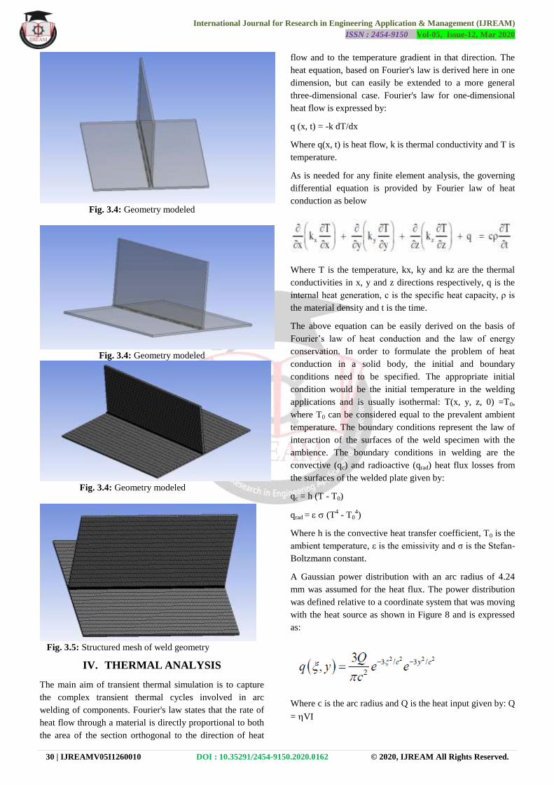
2.2 Finite Element Modeling
Structural and thermal finite element analyses were
performed using ANSYS to calculate residual stresses and
distortions in a flat-bar stiffened plate resulting from
welding the stiffener to the plate. The simulation consisted
of two analyses. The first was a transient thermal analysis
where the temperature distribution caused by a travelling
heat source was determined. The second step consisted of a
nonlinear structural analysis that was solved as a series of
sequential load steps. Each load step represented an
increment in the position of the heat source in the direction
of welding. The temperatures from the thermal analysis
associated with each load step were applied as loads in the
structural analysis. This process was repeated multiple times
until the welding was completed.
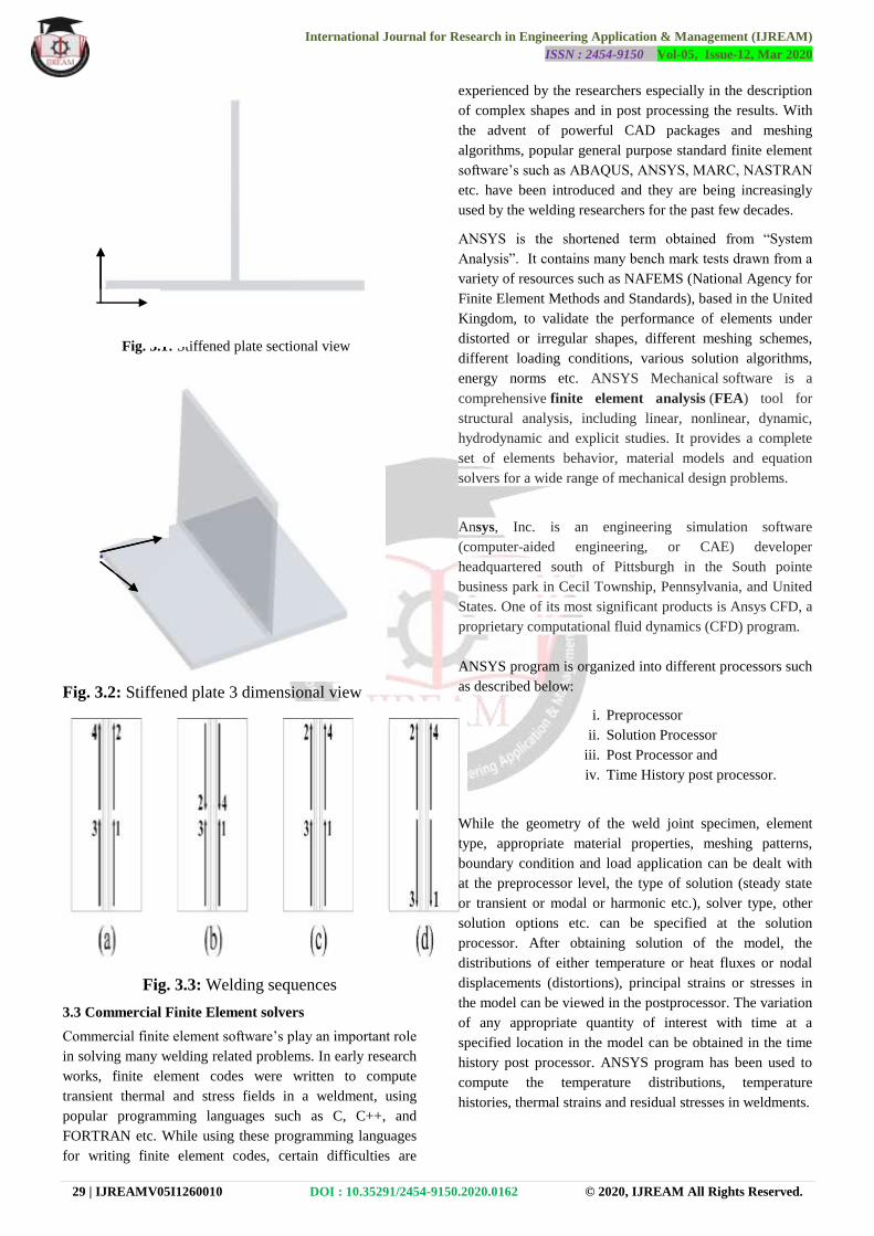
The plate and stiffener are both made from SM400A
shipbuilding steel with a chemical composition given in
Table 1. The plate is 150 mm x 150 mm with a thickness of
5 mm and the stiffener is 90 mm x 150 mm with a thickness
of 5 mm. The stiffener is connected to the plate by 4 mm
fillet welds deposited on both sides of the stiffener. The
geometry of the stiffened plate is shown in Figure 3.1 and
Figure 3.2 Four different welding sequences, shown in
Figure 3.3, were investigated.
Table 1: Chemical composition of SM400A steel by wt%
Chemical composition (mass %)
C Si Mn P S
0.23 - 0.56 <0.035 <0.035
International Journal for Research in Engineering Application & Management (IJREAM)
ISSN : 2454-9150 Vol-05, Issue-12, Mar 2020
29 | IJREAMV05I1260010 DOI : 10.35291/2454-9150.2020.0162 © 2020, IJREAM All Rights Reserved.
Fig. 3.1: Stiffened plate sectional view
Fig. 3.2: Stiffened plate 3 dimensional view
Fig. 3.3: Welding sequences
3.3 Commercial Finite Element solvers
Commercial finite element software’s play an important role
in solving many welding related problems. In early research
works, finite element codes were written to compute
transient thermal and stress fields in a weldment, using
popular programming languages such as C, C++, and
FORTRAN etc. While using these programming languages
for writing finite element codes, certain difficulties are
experienced by the researchers especially in the description
of complex shapes and in post processing the results. With
the advent of powerful CAD packages and meshing
algorithms, popular general purpose standard finite element
software’s such as ABAQUS, ANSYS, MARC, NASTRAN
etc. have been introduced and they are being increasingly
used by the welding researchers for the past few decades.
ANSYS is the shortened term obtained from ―System
Analysis‖. It contains many bench mark tests drawn from a
variety of resources such as NAFEMS (National Agency for
Finite Element Methods and Standards), based in the United
Kingdom, to validate the performance of elements under
distorted or irregular shapes, different meshing schemes,
different loading conditions, various solution algorithms,
energy norms etc. ANSYS Mechanical software is a
comprehensive finite element analysis (FEA) tool for
structural analysis, including linear, nonlinear, dynamic,
hydrodynamic and explicit studies. It provides a complete
set of elements behavior, material models and equation
solvers for a wide range of mechanical design problems.
Ansys, Inc. is an engineering simulation software
(computer-aided engineering, or CAE) developer
headquartered south of Pittsburgh in the South pointe
business park in Cecil Township, Pennsylvania, and United
States. One of its most significant products is Ansys CFD, a
proprietary computational fluid dynamics (CFD) program.
ANSYS program is organized into different processors such
as described below:
i. Preprocessor
ii. Solution Processor
iii. Post Processor and
iv. Time History post processor.
While the geometry of the weld joint specimen, element
type, appropriate material properties, meshing patterns,
boundary condition and load application can be dealt with
at the preprocessor level, the type of solution (steady state
or transient or modal or harmonic etc.), solver type, other
solution options etc. can be specified at the solution
processor. After obtaining solution of the model, the
distributions of either temperature or heat fluxes or nodal
displacements (distortions), principal strains or stresses in
the model can be viewed in the postprocessor. The variation
of any appropriate quantity of interest with time at a
specified location in the model can be obtained in the time
history post processor. ANSYS program has been used to
compute the temperature distributions, temperature
histories, thermal strains and residual stresses in weldments.
X
Origin
X
Y
Y
Z
International Journal for Research in Engineering Application & Management (IJREAM)
ISSN : 2454-9150 Vol-05, Issue-12, Mar 2020
30 | IJREAMV05I1260010 DOI : 10.35291/2454-9150.2020.0162 © 2020, IJREAM All Rights Reserved.
Fig. 3.4: Geometry modeled
Fig. 3.4: Geometry modeled
Fig. 3.4: Geometry modeled
Fig. 3.5: Structured mesh of weld geometry
IV. THERMAL ANALYSIS
The main aim of transient thermal simulation is to capture
the complex transient thermal cycles involved in arc
welding of components. Fourier's law states that the rate of
heat flow through a material is directly proportional to both
the area of the section orthogonal to the direction of heat
flow and to the temperature gradient in that direction. The
heat equation, based on Fourier's law is derived here in one
dimension, but can easily be extended to a more general
three-dimensional case. Fourier's law for one-dimensional
heat flow is expressed by:
q (x, t) = -k dT/dx
Where q(x, t) is heat flow, k is thermal conductivity and T is
temperature.
As is needed for any finite element analysis, the governing
differential equation is provided by Fourier law of heat
conduction as below
Where T is the temperature, kx, ky and kz are the thermal
conductivities in x, y and z directions respectively, q is the
internal heat generation, c is the specific heat capacity, ρ is
the material density and t is the time.
The above equation can be easily derived on the basis of
Fourier’s law of heat conduction and the law of energy
conservation. In order to formulate the problem of heat
conduction in a solid body, the initial and boundary
conditions need to be specified. The appropriate initial
condition would be the initial temperature in the welding
applications and is usually isothermal: T(x, y, z, 0) =T0,
where T0 can be considered equal to the prevalent ambient
temperature. The boundary conditions represent the law of
interaction of the surfaces of the weld specimen with the
ambience. The boundary conditions in welding are the
convective (qc) and radioactive (qrad) heat flux losses from
the surfaces of the welded plate given by:
qc = h (T - T0)
qrad = (T4 - T0
4)
Where h is the convective heat transfer coefficient, T0 is the
ambient temperature, ε is the emissivity and ζ is the Stefan-
Boltzmann constant.
A Gaussian power distribution with an arc radius of 4.24
mm was assumed for the heat flux. The power distribution
was defined relative to a coordinate system that was moving
with the heat source as shown in Figure 8 and is expressed
as:
Where c is the arc radius and Q is the heat input given by: Q
= VI
International Journal for Research in Engineering Application & Management (IJREAM)
ISSN : 2454-9150 Vol-05, Issue-12, Mar 2020
31 | IJREAMV05I1260010 DOI : 10.35291/2454-9150.2020.0162 © 2020, IJREAM All Rights Reserved.
Where, I is the current supplied, V is the voltage across the
arc and η is the arc efficiency which is assumed to be 0.8
for CO2 gas metal arc welding.
A summary of welding parameters is listed in Table 2.
Table 2: Welding conditions
Weld leg length
(mm)
Current (A) Voltage (V) Welding speed
(mm/min)
6 270 29 380
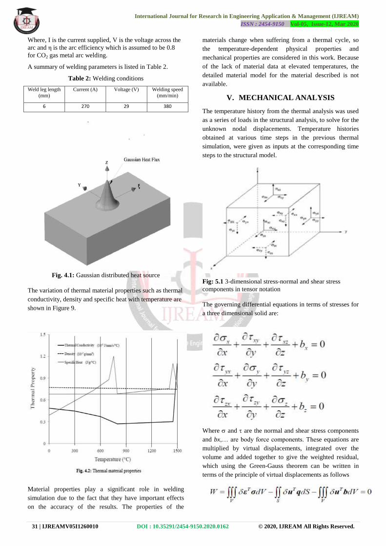
Fig. 4.1: Gaussian distributed heat source
The variation of thermal material properties such as thermal
conductivity, density and specific heat with temperature are
shown in Figure 9.
Material properties play a significant role in welding
simulation due to the fact that they have important effects
on the accuracy of the results. The properties of the
materials change when suffering from a thermal cycle, so
the temperature-dependent physical properties and
mechanical properties are considered in this work. Because
of the lack of material data at elevated temperatures, the
detailed material model for the material described is not
available.
V. MECHANICAL ANALYSIS
The temperature history from the thermal analysis was used
as a series of loads in the structural analysis, to solve for the
unknown nodal displacements. Temperature histories
obtained at various time steps in the previous thermal
simulation, were given as inputs at the corresponding time
steps to the structural model.
Fig: 5.1 3-dimensional stress-normal and shear stress
components in tensor notation
The governing differential equations in terms of stresses for
a three dimensional solid are:
Where and are the normal and shear stress components
and bx,… are body force components. These equations are
multiplied by virtual displacements, integrated over the
volume and added together to give the weighted residual,
which using the Green-Gauss theorem can be written in
terms of the principle of virtual displacements as follows
International Journal for Research in Engineering Application & Management (IJREAM)
ISSN : 2454-9150 Vol-05, Issue-12, Mar 2020
32 | IJREAMV05I1260010 DOI : 10.35291/2454-9150.2020.0162 © 2020, IJREAM All Rights Reserved.
Where σ = (x y z xy yz zx) T
are the normal and
shear stress components, δε = (δεx δεy δεz δγxy δγyz δγzx)
T and δu = (δu δv δw)
T are virtual strains and virtual
displacements respectively, q = (qx qy qz)T are applied
surface loads and b = (bx by bz)T are applied body forces.
When the relationship between stresses and strains in above
equation is nonlinear, the right hand side must be linearized
using the directional derivative giving a system of algebraic
equations of the form:
KT d = -rI + rq +rb
Where kT is the tangent stiffness matrix, Δd is the
incremental displacement vector, rI is the internal force
vector for the current solution and rq and rb are load
vectors due to distributed loads and body forces
respectively.
The modeling of the material behavior is a challenge as the
deformation mechanisms vary widely in the large
temperature range considered.
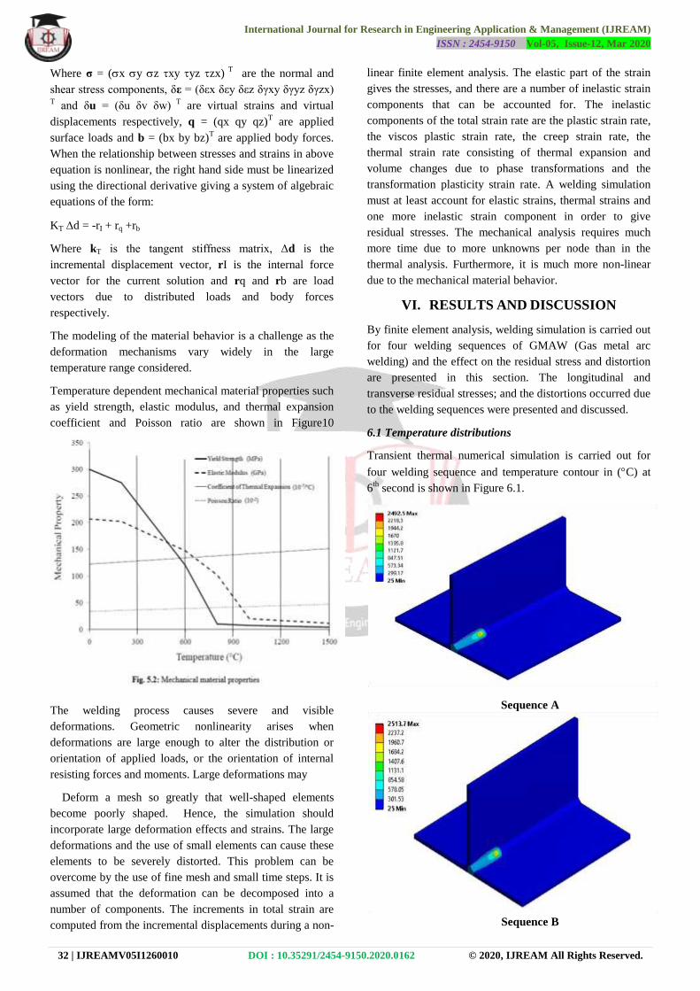
Temperature dependent mechanical material properties such
as yield strength, elastic modulus, and thermal expansion
coefficient and Poisson ratio are shown in Figure10
The welding process causes severe and visible
deformations. Geometric nonlinearity arises when
deformations are large enough to alter the distribution or
orientation of applied loads, or the orientation of internal
resisting forces and moments. Large deformations may
Deform a mesh so greatly that well-shaped elements
become poorly shaped. Hence, the simulation should
incorporate large deformation effects and strains. The large
deformations and the use of small elements can cause these
elements to be severely distorted. This problem can be
overcome by the use of fine mesh and small time steps. It is
assumed that the deformation can be decomposed into a
number of components. The increments in total strain are
computed from the incremental displacements during a non-
linear finite element analysis. The elastic part of the strain
gives the stresses, and there are a number of inelastic strain
components that can be accounted for. The inelastic
components of the total strain rate are the plastic strain rate,
the viscos plastic strain rate, the creep strain rate, the
thermal strain rate consisting of thermal expansion and
volume changes due to phase transformations and the
transformation plasticity strain rate. A welding simulation
must at least account for elastic strains, thermal strains and
one more inelastic strain component in order to give
residual stresses. The mechanical analysis requires much
more time due to more unknowns per node than in the
thermal analysis. Furthermore, it is much more non-linear
due to the mechanical material behavior.
VI. RESULTS AND DISCUSSION
By finite element analysis, welding simulation is carried out
for four welding sequences of GMAW (Gas metal arc
welding) and the effect on the residual stress and distortion
are presented in this section. The longitudinal and
transverse residual stresses; and the distortions occurred due
to the welding sequences were presented and discussed.
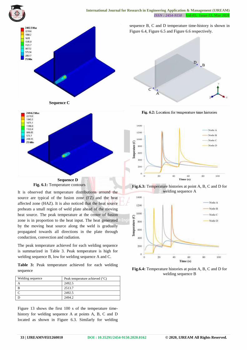
6.1 Temperature distributions
Transient thermal numerical simulation is carried out for
four welding sequence and temperature contour in (C) at
6th
second is shown in Figure 6.1.
Sequence A
Sequence B
International Journal for Research in Engineering Application & Management (IJREAM)
ISSN : 2454-9150 Vol-05, Issue-12, Mar 2020
33 | IJREAMV05I1260010 DOI : 10.35291/2454-9150.2020.0162 © 2020, IJREAM All Rights Reserved.
Sequence C
Sequence D
Fig. 6.1: Temperature contours
It is observed that temperature distributions around the
source are typical of the fusion zone (FZ) and the heat
affected zone (HAZ). It is also noticed that the heat source
preheats a small region of weld plate ahead of the moving
heat source. The peak temperature at the center of fusion
zone is in proportion to the heat input. The heat generated
by the moving heat source along the weld is gradually
propagated towards all directions in the plate through
conduction, convection and radiation.
The peak temperature achieved for each welding sequence
is summarized in Table 3. Peak temperature is high for
welding sequence B, low for welding sequence A and C.
Table 3: Peak temperature achieved for each welding
sequence
Welding sequence Peak temperature achieved (C)
A 2492.5
B 2513.7
C 2492.5
D 2494.2
Figure 13 shows the first 100 s of the temperature time-
history for welding sequence A at points A, B, C and D
located as shown in Figure 6.3. Similarly for welding
sequence B, C and D temperature time-history is shown in
Figure 6.4, Figure 6.5 and Figure 6.6 respectively.
Fig.6.3: Temperature histories at point A, B, C and D for
welding sequence A
Fig.6.4: Temperature histories at point A, B, C and D for
welding sequence B
B
International Journal for Research in Engineering Application & Management (IJREAM)
ISSN : 2454-9150 Vol-05, Issue-12, Mar 2020
34 | IJREAMV05I1260010 DOI : 10.35291/2454-9150.2020.0162 © 2020, IJREAM All Rights Reserved.
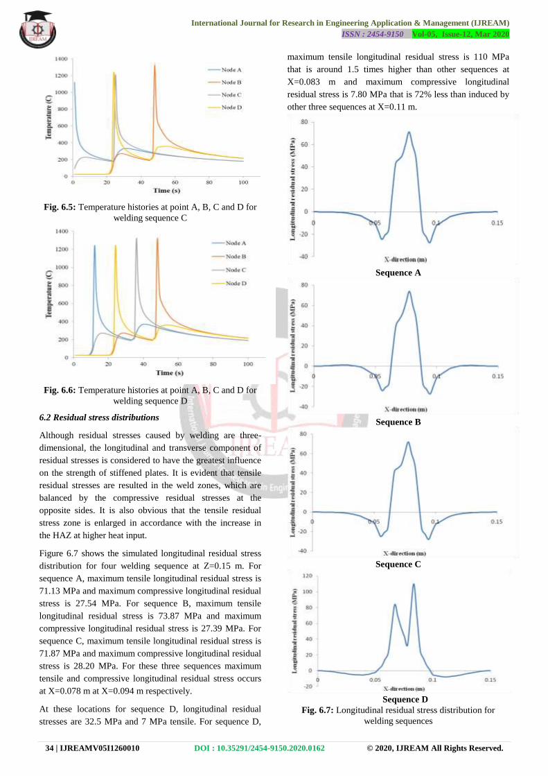
Fig. 6.5: Temperature histories at point A, B, C and D for
welding sequence C
Fig. 6.6: Temperature histories at point A, B, C and D for
welding sequence D
6.2 Residual stress distributions
Although residual stresses caused by welding are three-
dimensional, the longitudinal and transverse component of
residual stresses is considered to have the greatest influence
on the strength of stiffened plates. It is evident that tensile
residual stresses are resulted in the weld zones, which are
balanced by the compressive residual stresses at the
opposite sides. It is also obvious that the tensile residual
stress zone is enlarged in accordance with the increase in
the HAZ at higher heat input.
Figure 6.7 shows the simulated longitudinal residual stress
distribution for four welding sequence at Z=0.15 m. For
sequence A, maximum tensile longitudinal residual stress is
71.13 MPa and maximum compressive longitudinal residual
stress is 27.54 MPa. For sequence B, maximum tensile
longitudinal residual stress is 73.87 MPa and maximum
compressive longitudinal residual stress is 27.39 MPa. For
sequence C, maximum tensile longitudinal residual stress is
71.87 MPa and maximum compressive longitudinal residual
stress is 28.20 MPa. For these three sequences maximum
tensile and compressive longitudinal residual stress occurs
at X=0.078 m at X=0.094 m respectively.
At these locations for sequence D, longitudinal residual
stresses are 32.5 MPa and 7 MPa tensile. For sequence D,
maximum tensile longitudinal residual stress is 110 MPa
that is around 1.5 times higher than other sequences at
X=0.083 m and maximum compressive longitudinal
residual stress is 7.80 MPa that is 72% less than induced by
other three sequences at X=0.11 m.
Sequence A
Sequence B
Sequence C
Sequence D
Fig. 6.7: Longitudinal residual stress distribution for
welding sequences
International Journal for Research in Engineering Application & Management (IJREAM)
ISSN : 2454-9150 Vol-05, Issue-12, Mar 2020
35 | IJREAMV05I1260010 DOI : 10.35291/2454-9150.2020.0162 © 2020, IJREAM All Rights Reserved.
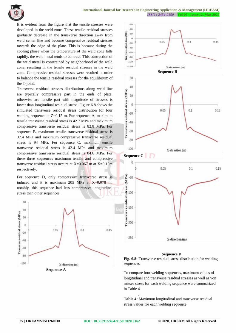
It is evident from the figure that the tensile stresses were
developed in the weld zone. These tensile residual stresses
gradually decrease in the transverse direction away from
weld center line and become compressive residual stresses
towards the edge of the plate. This is because during the
cooling phase when the temperature of the weld zone falls
rapidly, the weld metal tends to contract. This contraction of
the weld metal is constrained by neighborhood of the weld
zone, resulting in the tensile residual stresses in the weld
zone. Compressive residual stresses were resulted in order
to balance the tensile residual stresses for the equilibrium of
the T-joint.
Transverse residual stresses distributions along weld line
are typically compressive part in the ends of plate,
otherwise are tensile part with magnitude of stresses is
lower than longitudinal residual stress. Figure 6.8 shows the
simulated transverse residual stress distribution for four
welding sequence at Z=0.15 m. For sequence A, maximum
tensile transverse residual stress is 42.7 MPa and maximum
compressive transverse residual stress is 82.8 MPa. For
sequence B, maximum tensile transverse residual stress is
37.4 MPa and maximum compressive transverse residual
stress is 94 MPa. For sequence C, maximum tensile
transverse residual stress is 42.4 MPa and maximum
compressive transverse residual stress is 84.6 MPa. For
these three sequences maximum tensile and compressive
transverse residual stress occurs at X=0.067 m at X=0.15m
respectively.
For sequence D, only compressive transverse stress is
induced and it is maximum 205 MPa at X=0.078 m.
notably, this sequence had less compressive longitudinal
stress than other sequences.
Sequence A
Sequence B
Sequence C
Sequence D
Fig. 6.8: Transverse residual stress distribution for welding
sequences
To compare four welding sequences, maximum values of
longitudinal and transverse residual stresses as well as von
misses stress for each welding sequence were summarized
in Table 4
.
Table 4: Maximum longitudinal and transverse residual
stress values for each welding sequence
International Journal for Research in Engineering Application & Management (IJREAM)
ISSN : 2454-9150 Vol-05, Issue-12, Mar 2020
36 | IJREAMV05I1260010 DOI : 10.35291/2454-9150.2020.0162 © 2020, IJREAM All Rights Reserved.
Weldi
ng
seque
nce
Maximum longitudinal
stress (MPa)
Maximum transverse
stress (MPa)
Maximu
m
von
misses
stress
(MPa)
Tensile Compressiv
e
Tensil
e
Compressiv
e
A 824 818.4 661 702.3 1310.9
B 953.8 840.2 676 702.8 1310.4
C 824 823 664 702 1312.5
D 840.3 519.3 529.8 598.8 1208.5
Maximum tensile and compressive longitudinal and
transverse residual stress occurs for welding sequence B.
Maximum von misses stress occurs for sequence C whereas
for sequence A and B are also closer to maximum. For
sequence D, tensile and compressive transverse residual
stress and von misses stress are less than other three
sequences.
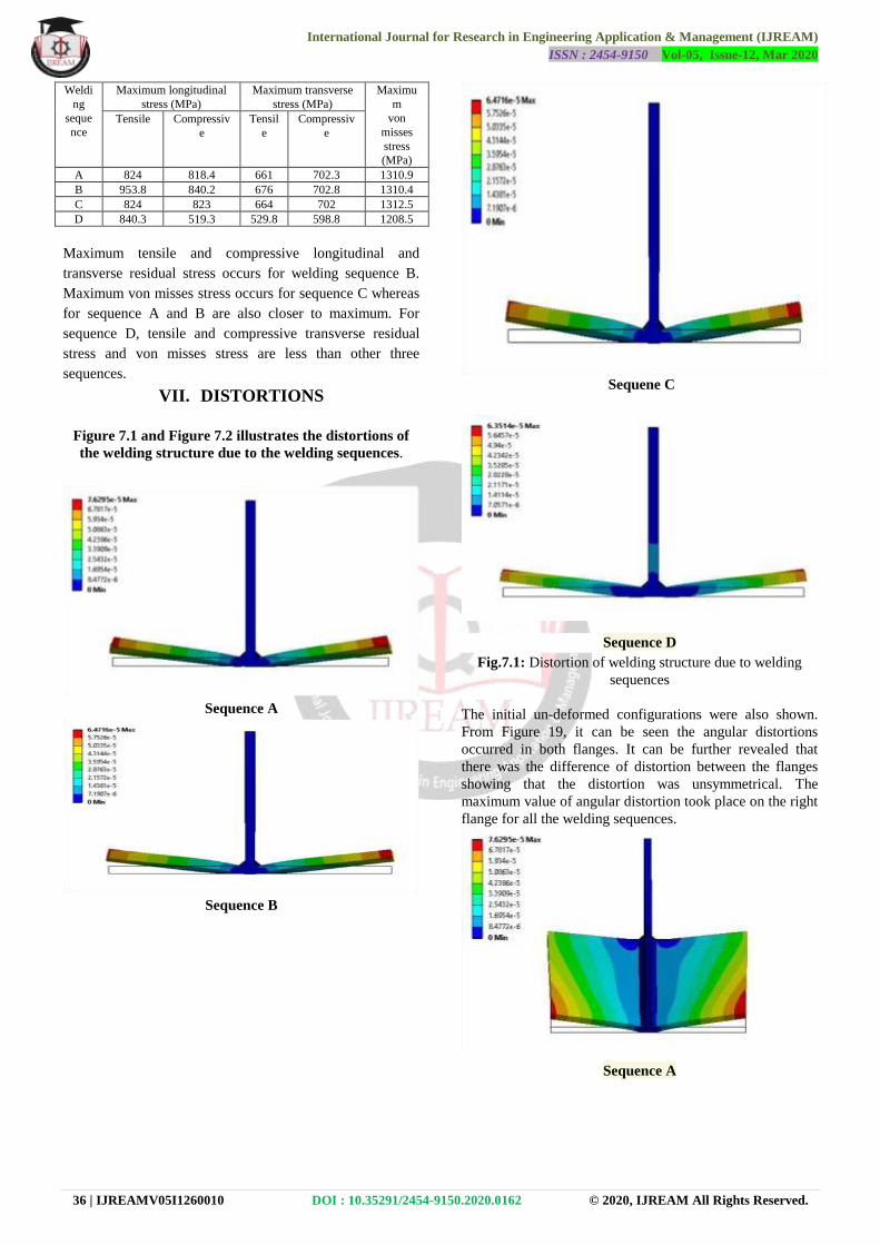
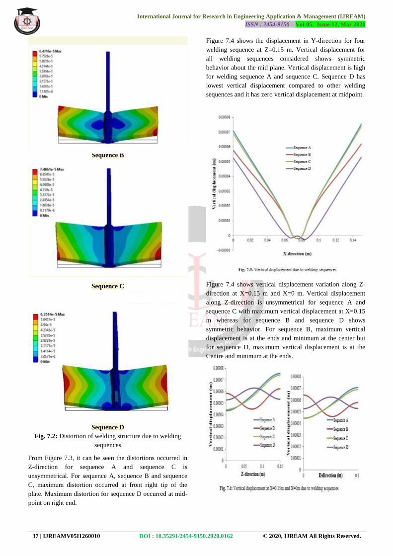
VII. DISTORTIONS
Figure 7.1 and Figure 7.2 illustrates the distortions of
the welding structure due to the welding sequences.
Sequence A
Sequence B
Sequene C
Sequence D
Fig.7.1: Distortion of welding structure due to welding
sequences
The initial un-deformed configurations were also shown.
From Figure 19, it can be seen the angular distortions
occurred in both flanges. It can be further revealed that
there was the difference of distortion between the flanges
showing that the distortion was unsymmetrical. The
maximum value of angular distortion took place on the right
flange for all the welding sequences.
Sequence A
International Journal for Research in Engineering Application & Management (IJREAM)
ISSN : 2454-9150 Vol-05, Issue-12, Mar 2020
37 | IJREAMV05I1260010 DOI : 10.35291/2454-9150.2020.0162 © 2020, IJREAM All Rights Reserved.
Sequence B
Sequence C
Sequence D
Fig. 7.2: Distortion of welding structure due to welding
sequences
From Figure 7.3, it can be seen the distortions occurred in
Z-direction for sequence A and sequence C is
unsymmetrical. For sequence A, sequence B and sequence
C, maximum distortion occurred at front right tip of the
plate. Maximum distortion for sequence D occurred at mid-
point on right end.
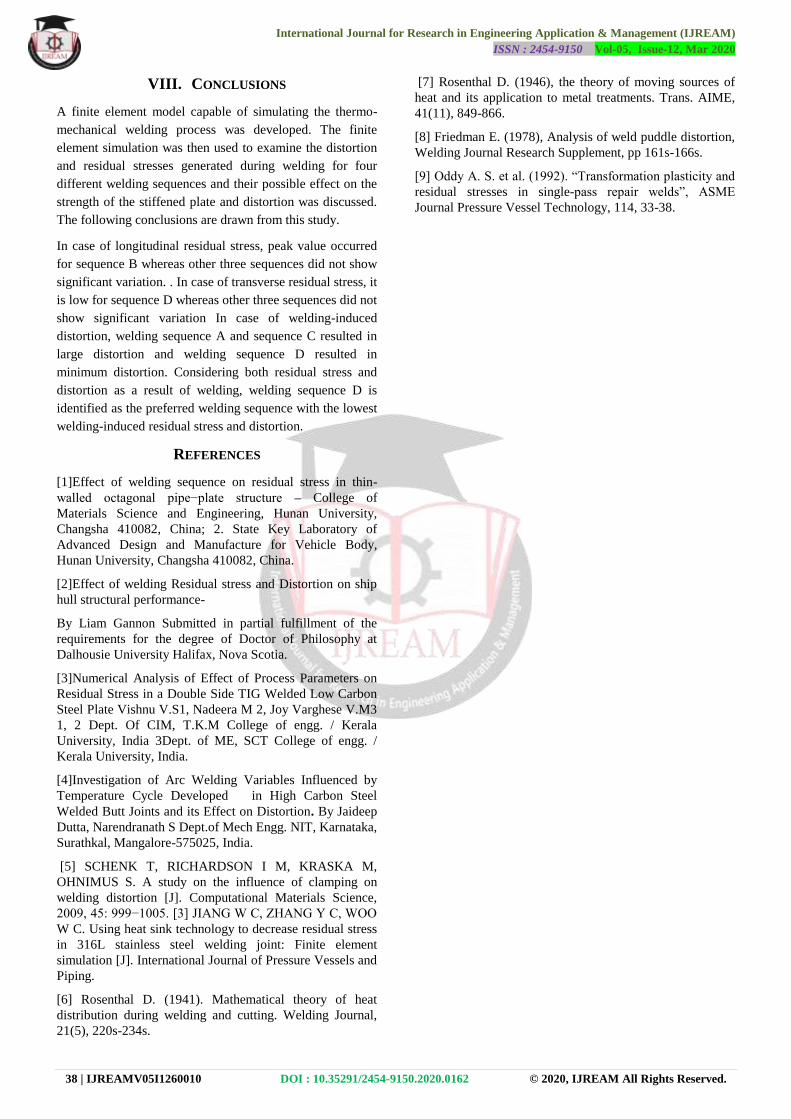
Figure 7.4 shows the displacement in Y-direction for four
welding sequence at Z=0.15 m. Vertical displacement for
all welding sequences considered shows symmetric
behavior about the mid plane. Vertical displacement is high
for welding sequence A and sequence C. Sequence D has
lowest vertical displacement compared to other welding
sequences and it has zero vertical displacement at midpoint.
Figure 7.4 shows vertical displacement variation along Z-
direction at X=0.15 m and X=0 m. Vertical displacement
along Z-direction is unsymmetrical for sequence A and
sequence C with maximum vertical displacement at X=0.15
m whereas for sequence B and sequence D shows
symmetric behavior. For sequence B, maximum vertical
displacement is at the ends and minimum at the center but
for sequence D, maximum vertical displacement is at the
Centre and minimum at the ends.
International Journal for Research in Engineering Application & Management (IJREAM)
ISSN : 2454-9150 Vol-05, Issue-12, Mar 2020
38 | IJREAMV05I1260010 DOI : 10.35291/2454-9150.2020.0162 © 2020, IJREAM All Rights Reserved.
VIII. CONCLUSIONS
A finite element model capable of simulating the thermo-
mechanical welding process was developed. The finite
element simulation was then used to examine the distortion
and residual stresses generated during welding for four
different welding sequences and their possible effect on the
strength of the stiffened plate and distortion was discussed.
The following conclusions are drawn from this study.
In case of longitudinal residual stress, peak value occurred
for sequence B whereas other three sequences did not show
significant variation. . In case of transverse residual stress, it
is low for sequence D whereas other three sequences did not
show significant variation In case of welding-induced
distortion, welding sequence A and sequence C resulted in
large distortion and welding sequence D resulted in
minimum distortion. Considering both residual stress and
distortion as a result of welding, welding sequence D is
identified as the preferred welding sequence with the lowest
welding-induced residual stress and distortion.
REFERENCES
[1]Effect of welding sequence on residual stress in thin-
walled octagonal pipe−plate structure – College of
Materials Science and Engineering, Hunan University,
Changsha 410082, China; 2. State Key Laboratory of
Advanced Design and Manufacture for Vehicle Body,
Hunan University, Changsha 410082, China.
[2]Effect of welding Residual stress and Distortion on ship
hull structural performance-
By Liam Gannon Submitted in partial fulfillment of the
requirements for the degree of Doctor of Philosophy at
Dalhousie University Halifax, Nova Scotia.
[3]Numerical Analysis of Effect of Process Parameters on
Residual Stress in a Double Side TIG Welded Low Carbon
Steel Plate Vishnu V.S1, Nadeera M 2, Joy Varghese V.M3
1, 2 Dept. Of CIM, T.K.M College of engg. / Kerala
University, India 3Dept. of ME, SCT College of engg. /
Kerala University, India.
[4]Investigation of Arc Welding Variables Influenced by
Temperature Cycle Developed in High Carbon Steel
Welded Butt Joints and its Effect on Distortion. By Jaideep
Dutta, Narendranath S Dept.of Mech Engg. NIT, Karnataka,
Surathkal, Mangalore-575025, India.
[5] SCHENK T, RICHARDSON I M, KRASKA M,
OHNIMUS S. A study on the influence of clamping on
welding distortion [J]. Computational Materials Science,
2009, 45: 999−1005. [3] JIANG W C, ZHANG Y C, WOO
W C. Using heat sink technology to decrease residual stress
in 316L stainless steel welding joint: Finite element
simulation [J]. International Journal of Pressure Vessels and
Piping.
[6] Rosenthal D. (1941). Mathematical theory of heat
distribution during welding and cutting. Welding Journal,
21(5), 220s-234s.
[7] Rosenthal D. (1946), the theory of moving sources of
heat and its application to metal treatments. Trans. AIME,
41(11), 849-866.
[8] Friedman E. (1978), Analysis of weld puddle distortion,
Welding Journal Research Supplement, pp 161s-166s.
[9] Oddy A. S. et al. (1992). ―Transformation plasticity and
residual stresses in single-pass repair welds‖, ASME
Journal Pressure Vessel Technology, 114, 33-38.
Recommended