11111
K8NF6P-VSTA
User Manual
Version 1.0Published February 2007
Copyright©2007 ASRock INC. All rights reserved.
22222
Copyright Notice:Copyright Notice:Copyright Notice:Copyright Notice:Copyright Notice:No part of this manual may be reproduced, transcribed, transmitted, or translated inany language, in any form or by any means, except duplication of documentation bythe purchaser for backup purpose, without written consent of ASRock Inc.Products and corporate names appearing in this manual may or may not be regis-tered trademarks or copyrights of their respective companies, and are used only foridentification or explanation and to the owners’ benefit, without intent to infringe.
Disclaimer:Disclaimer:Disclaimer:Disclaimer:Disclaimer:Specifications and information contained in this manual are furnished for informa-tional use only and subject to change without notice, and should not be constructedas a commitment by ASRock. ASRock assumes no responsibility for any errors oromissions that may appear in this manual.With respect to the contents of this manual, ASRock does not provide warranty ofany kind, either expressed or implied, including but not limited to the implied warran-ties or conditions of merchantability or fitness for a particular purpose.In no event shall ASRock, its directors, officers, employees, or agents be liable forany indirect, special, incidental, or consequential damages (including damages forloss of profits, loss of business, loss of data, interruption of business and the like),even if ASRock has been advised of the possibility of such damages arising from anydefect or error in the manual or product.
This device complies with Part 15 of the FCC Rules. Operation is subject to thefollowing two conditions:(1) this device may not cause harmful interference, and(2) this device must accept any interference received, including interference that
may cause undesired operation.
CALIFORNIA, USA ONLYThe Lithium battery adopted on this motherboard contains Perchlorate, a toxicsubstance controlled in Perchlorate Best Management Practices (BMP) regulationspassed by the California Legislature. When you discard the Lithium battery inCalifornia, USA, please follow the related regulations in advance.“Perchlorate Material-special handling may apply, seewww.dtsc.ca.gov/hazardouswaste/perchlorate”
ASRock Website: http://www.asrock.com
33333
ContentsContentsContentsContentsContents1.1.1.1.1. IntroductionIntroductionIntroductionIntroductionIntroduction ............................................................................................................................................................................................................................................................................................................ 5 5 5 5 5
1.1 Package Contents ..................................................................... 51.2 Specifications ........................................................................... 61.3 Minimum Hardware Requirement Table for Windows® VistaTM
Basic Logo ................................................................................ 91.4 Motherboard Layout ................................................................. 101.5 HD 8CH I/O ................................................................................ 11
2.2.2.2.2. InstallationInstallationInstallationInstallationInstallation ...................................................................................................................................................................................................................................................................................................................... 12 12 12 12 12Pre-installation Precautions ............................................................... 122.1 CPU Installation ......................................................................... 132.2 Installation of CPU Fan and Heatsink ....................................... 132.3 Installation of Memory Modules (DIMM) .................................... 142.4 Expansion Slots (PCI, HDMR and PCI Express Slots) ..................... 152.5 Easy Multi Monitor Feature ........................................................ 162.6 Jumpers Setup .......................................................................... 172.7 Onboard Headers and Connectors .......................................... 182.8 SATAII Hard Disk Setup Guide .................................................. 222.9 Serial ATA (SATA) / Serial ATAII (SATAII) Hard Disks
Installation ................................................................................. 232.10 Hot Plug and Hot Swap Functions for SATA / SATAII HDDs .... 232.11 Driver Installation Guide ............................................................ 232.12 HDMR Card and Driver Installation ............................................ 242.13 Installing Windows® 2000 / XP / XP 64-bit / VistaTM /
VistaTM 64-bit Without RAID Functions ..................................... 242.14 Installing Windows® 2000 / XP / XP 64-bit / VistaTM /
VistaTM 64-bit With RAID Functions ........................................... 242.14.1 Installing Windows® 2000 / XP / XP 64-bit With RAID
Functions ...................................................................... 252.14.2 Installing Windows® VistaTM / VistaTM 64-bit With RAID
Functions ...................................................................... 262.15 Untied Overclocking Technology .............................................. 27
3.3.3.3.3. BIOS SBIOS SBIOS SBIOS SBIOS SETUP UTILITYETUP UTILITYETUP UTILITYETUP UTILITYETUP UTILITY ............................................................................................................................................................................................................................................................... 27 27 27 27 273.1 Introduction ............................................................................... 27
3.1.1 BIOS Menu Bar ............................................................... 273.1.2 Navigation Keys ............................................................. 28
3.2 Main Screen .............................................................................. 293.3 Advanced Screen .................................................................... 29
3.3.1 CPU Configuration .......................................................... 293.3.2 Chipset Configuration ..................................................... 32
44444
3.3.3 ACPI Configuration ......................................................... 333.3.4 IDE Configuration ............................................................ 343.3.5 PCIPnP Configuration ...................................................... 363.3.6 Floppy Configuration ...................................................... 373.3.7 Super IO Configuration ................................................... 373.3.8 USB Configuration .......................................................... 38
3.4 Hardware Health Event Monitoring Screen ............................. 393.5 Boot Screen .............................................................................. 40
3.5.1 Boot Settings Configuration ........................................... 403.6 Security Screen ........................................................................ 413.7 Exit Screen ............................................................................... 42
4.4.4.4.4. Software SupportSoftware SupportSoftware SupportSoftware SupportSoftware Support ............................................................................................................................................................................................................................................................... 43 43 43 43 434.1 Install Operating System ........................................................... 434.2 Support CD Information ............................................................. 43
4.2.1 Running Support CD ....................................................... 434.2.2 Drivers Menu .................................................................. 434.2.3 Utilities Menu ................................................................... 434.2.4 Contact Information ........................................................ 43
55555
1.1.1.1.1. IntroductionIntroductionIntroductionIntroductionIntroductionThank you for purchasing ASRock K8NF6P-VSTA motherboard, a reliable motherboardproduced under ASRock’s consistently stringent quality control. It delivers excellentperformance with robust design conforming to ASRock’s commitment to quality andendurance.In this manual, chapter 1 and 2 contain introduction of the motherboard and step-by-step guide to the hardware installation. Chapter 3 and 4 contain the configurationguide to BIOS setup and information of the Support CD.
Because the motherboard specifications and the BIOS software might beupdated, the content of this manual will be subject to change withoutnotice. In case any modifications of this manual occur, the updatedversion will be available on ASRock website without further notice. Youmay find the latest VGA cards and CPU support lists on ASRock websiteas well. ASRock website http://www.asrock.com
1.11.11.11.11.1 Package ContentsPackage ContentsPackage ContentsPackage ContentsPackage Contents1 x ASRock K8NF6P-VSTA Motherboard
(Micro ATX Form Factor: 9.6-in x 8.2-in, 24.4 cm x 20.8 cm)1 x ASRock K8NF6P-VSTA Quick Installation Guide1 x ASRock K8NF6P-VSTA Support CD1 x Ultra ATA 66/100/133 IDE Ribbon Cable (80-conductor)1 x 3.5-in Floppy Drive Ribbon Cable1 x Serial ATA (SATA) Data Cable (Optional)1 x Serial ATA (SATA) HDD Power Cable (Optional)1 x HD 8CH I/O Shield1 x COM Port Bracket
66666
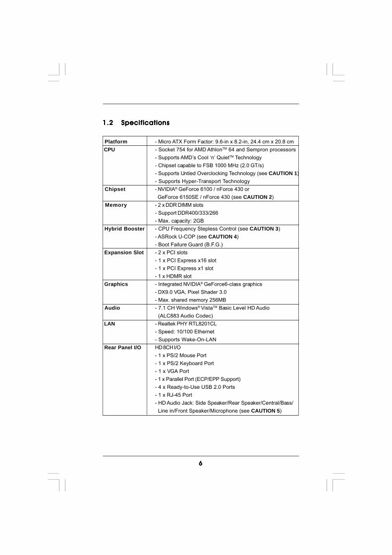
1.21.21.21.21.2 SpecificationsSpecificationsSpecificationsSpecificationsSpecifications
Platform - Micro ATX Form Factor: 9.6-in x 8.2-in, 24.4 cm x 20.8 cm CPU - Socket 754 for AMD AthlonTM 64 and Sempron processors
- Supports AMD’s Cool ‘n’ QuietTM Technology- Chipset capable to FSB 1000 MHz (2.0 GT/s)- Supports Untied Overclocking Technology (see CAUTION 1)- Supports Hyper-Transport Technology
Chipset - NVIDIA® GeForce 6100 / nForce 430 or GeForce 6150SE / nForce 430 (see CAUTION 2)
Memory - 2 x DDR DIMM slots- Support DDR400/333/266- Max. capacity: 2GB
Hybrid Booster - CPU Frequency Stepless Control (see CAUTION 3)- ASRock U-COP (see CAUTION 4)- Boot Failure Guard (B.F.G.)
Expansion Slot - 2 x PCI slots- 1 x PCI Express x16 slot- 1 x PCI Express x1 slot- 1 x HDMR slot
Graphics - Integrated NVIDIA® GeForce6-class graphics- DX9.0 VGA, Pixel Shader 3.0- Max. shared memory 256MB
Audio - 7.1 CH Windows® VistaTM Basic Level HD Audio (ALC883 Audio Codec)
LAN - Realtek PHY RTL8201CL- Speed: 10/100 Ethernet- Supports Wake-On-LAN
Rear Panel I/O HD 8CH I/O- 1 x PS/2 Mouse Port- 1 x PS/2 Keyboard Port- 1 x VGA Port- 1 x Parallel Port (ECP/EPP Support)- 4 x Ready-to-Use USB 2.0 Ports- 1 x RJ-45 Port- HD Audio Jack: Side Speaker/Rear Speaker/Central/Bass/ Line in/Front Speaker/Microphone (see CAUTION 5)

77777
Connector - 4 x Serial ATAII 3.0Gb/s connectors, support RAID (RAID 0, RAID 1, RAID 0+1, JBOD, RAID 5), NCQ and “Hot Plug” functions (see CAUTION 6)- 1 x ATA133 IDE connector (supports 2 x IDE devices)- 1 x Floppy connector- 1 x IR header- 1 x Game header- 1 x COM port header- CPU/Chassis FAN connector- 20 pin ATX power connector- 4 pin 12V power connector- CD in header- Front panel audio connector- 3 x USB 2.0 headers (support 6 USB 2.0 ports) (see CAUTION 7)
BIOS Feature - 4Mb AMI BIOS- AMI Legal BIOS- Supports “Plug and Play”- ACPI 1.1 Compliance Wake Up Events- Supports jumperfree- SMBIOS 2.3.1 Support
Support CD - Drivers, Utilities, AntiVirus Software (Trial Version) Hardware - CPU Temperature Sensing Monitor - Chassis Temperature Sensing
- CPU Fan Tachometer- Chassis Fan Tachometer- CPU Quiet Fan- Voltage Monitoring: +12V, +5V, +3.3V, Vcore
OS - Microsoft® Windows® 2000/XP/XP 64-bit/VistaTM/ VistaTM 64-bit compliant (see CAUTION 8)
Certifications - FCC, CE, Microsoft® WHQL Certificated
WARNINGPlease realize that there is a certain risk involved with overclocking, including adjustingthe setting in the BIOS, applying Untied Overclocking Technology, or using the third-party overclocking tools. Overclocking may affect your system stability, or evencause damage to the components and devices of your system. It should be done atyour own risk and expense. We are not responsible for possible damage caused byoverclocking.
88888
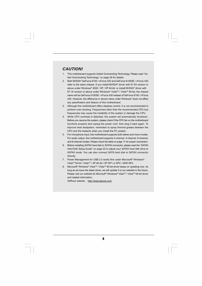
CAUTION!1. This motherboard supports Untied Overclocking Technology. Please read “Un-
tied Overclocking Technology” on page 26 for details.2. Both NVIDIA® GeForce 6100 / nForce 430 and GeForce 6150SE / nForce 430
refer to the same chipset. If you install NVIDIA® driver with 91.63 version orabove under Windows® 2000 / XP / XP 64-bit, or install NVIDIA® driver with97.19 version or above under Windows® VistaTM / VistaTM 64-bit, the chipsetname will be GeForce 6150SE / nForce 430 instead of GeForce 6100 / nForce430. However, the difference in device name under Windows® does not affectany specification and feature of this motherboard.
3. Although this motherboard offers stepless control, it is not recommended toperform over-clocking. Frequencies other than the recommended CPU busfrequencies may cause the instability of the system or damage the CPU.
4. While CPU overheat is detected, the system will automatically shutdown.Before you resume the system, please check if the CPU fan on the motherboardfunctions properly and unplug the power cord, then plug it back again. Toimprove heat dissipation, remember to spray thermal grease between theCPU and the heatsink when you install the PC system.
5. For microphone input, this motherboard supports both stereo and mono modes.For audio output, this motherboard supports 2-channel, 4-channel, 6-channel,and 8-channel modes. Please check the table on page 11 for proper connection.
6. Before installing SATAII hard disk to SATAII connector, please read the “SATAIIHard Disk Setup Guide” on page 22 to adjust your SATAII hard disk drive toSATAII mode. You can also connect SATA hard disk to SATAII connectordirectly.
7. Power Management for USB 2.0 works fine under Microsoft® Windows®
VistaTM 64-bit / VistaTM / XP 64-bit / XP SP1 or SP2 / 2000 SP4.8. Microsoft® Windows® VistaTM / VistaTM 64-bit driver keeps on updating now. As
long as we have the latest driver, we will update it to our website in the future.Please visit our website for Microsoft® Windows® VistaTM / VistaTM 64-bit driverand related information.ASRock website http://www.asrock.com
99999
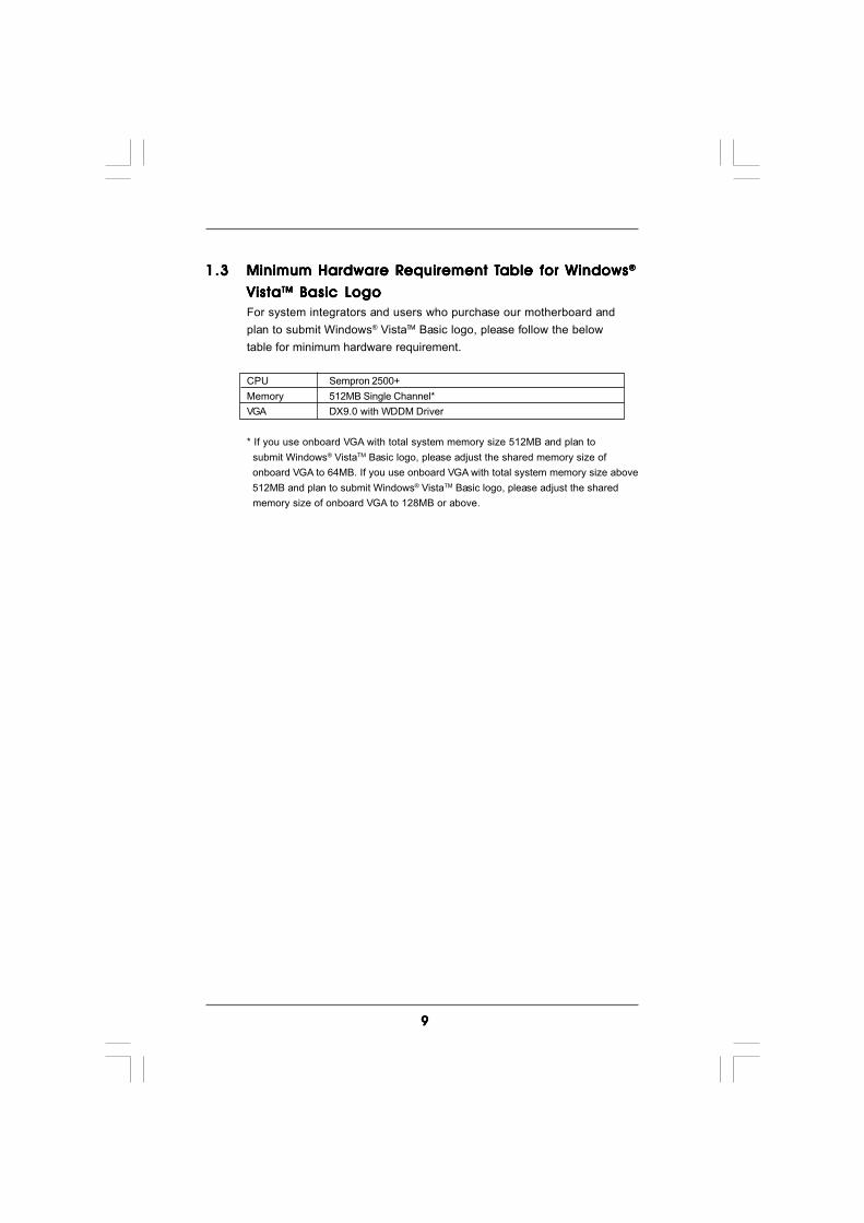
1.31.31.31.31.3 Minimum Hardware RMinimum Hardware RMinimum Hardware RMinimum Hardware RMinimum Hardware Requirement Tequirement Tequirement Tequirement Tequirement Table for Wable for Wable for Wable for Wable for Windowsindowsindowsindowsindows®®®®®
VistaVistaVistaVistaVistaTMTMTMTMTM Basic Logo Basic Logo Basic Logo Basic Logo Basic LogoFor system integrators and users who purchase our motherboard andplan to submit Windows® VistaTM Basic logo, please follow the belowtable for minimum hardware requirement.
CPU Sempron 2500+Memory 512MB Single Channel*VGA DX9.0 with WDDM Driver
* If you use onboard VGA with total system memory size 512MB and plan to submit Windows® VistaTM Basic logo, please adjust the shared memory size of onboard VGA to 64MB. If you use onboard VGA with total system memory size above 512MB and plan to submit Windows® VistaTM Basic logo, please adjust the shared memory size of onboard VGA to 128MB or above.
1 01 01 01 01 0
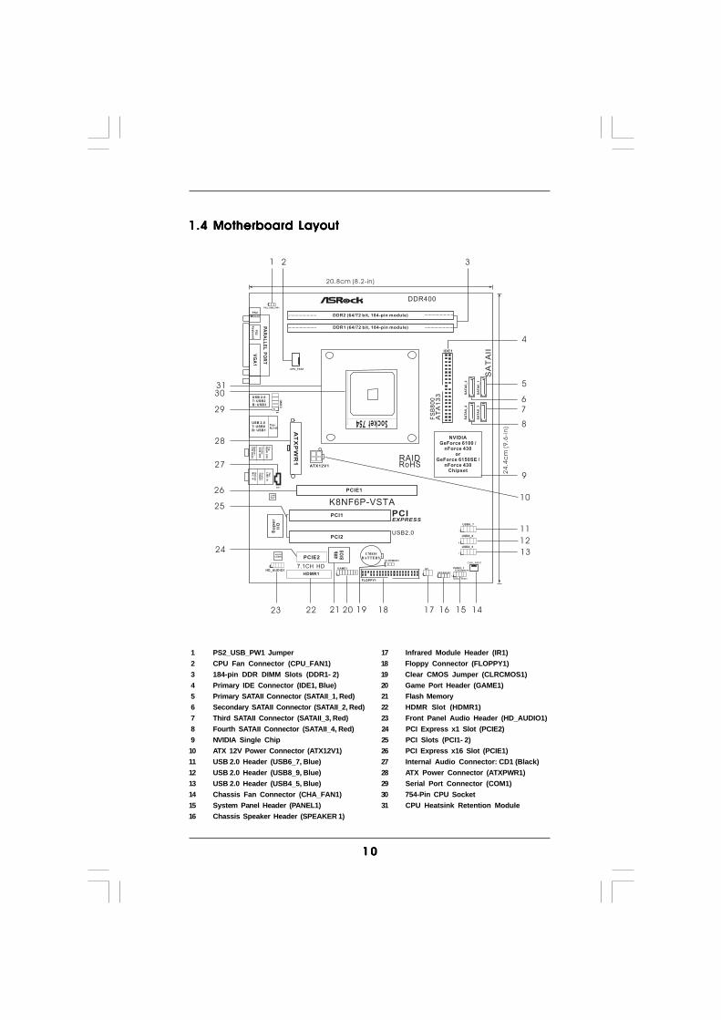
1.4 Motherboard Layout1.4 Motherboard Layout1.4 Motherboard Layout1.4 Motherboard Layout1.4 Motherboard Layout
Socket754
USB 2.0T: USB2B: USB3
PA
RA
LL
EL
PO
RT
VG
A1
PS2
Mouse
PS
2K
ey
bo
ard
To
p:
RE
AR
SP
K
Ce
nte
r:S
IDE
SP
K
Bo
ttom
:C
TR
BA
SS
To
p:
LIN
EIN
Ce
nte
r:F
RO
NT
Bo
ttom
:M
ICIN
USB 2.0T: USB0B: USB1
Top:RJ-45
AT
XP
WR
1
SA
TA
II
PCIEXPRESS
USB2.0
PCIE2
SA
TA
II_
1
SA
TA
II_
2
Su
pe
rI/
O
PS2_USB_PW1
1
ATX12V1
FSB800DDR2 (64/72 bit, 184-pin module)
DDR1 (64/72 bit, 184-pin module)
DDR400
NVIDIAGeForce 6100 /
nForce 430or
GeForce 6150SE /nForce 430
Chipset
AUDIOCODEC
LANPHY
IDE1
AT
A1
33
4Mb
BIO
S
CMOSBATTERY
K8NF6P-VSTA
7.1CH HD
CPU_FAN1
FLOPPY1HDLED RESET
PLED PWRBTN
1
PANEL 1IR1
USB6_7
1
USB4_5
1
CHA_FAN1
SPEAKER1
1
CLRCMOS1
HD_AUDIO1
1GAME1
1HDMR1
20.8cm (8.2-in)
24
.4c
m(9
.6-i
n)
CO
M1
1
1 2
4
3
5
6
8
9
11
13
14151617181920212223
24
25
26
27
28
1
RoHSRAID
PCIE1
PCI1
PCI2
1
FS
B8
00
CD1
SA
TA
II_
3
SA
TA
II_
4
7
121
USB8_9
10
29
3031
1 PS2_USB_PW1 Jumper 17 Infrared Module Header (IR1) 2 CPU Fan Connector (CPU_FAN1) 18 Floppy Connector (FLOPPY1) 3 184-pin DDR DIMM Slots (DDR1- 2) 19 Clear CMOS Jumper (CLRCMOS1) 4 Primary IDE Connector (IDE1, Blue) 20 Game Port Header (GAME1) 5 Primary SATAII Connector (SATAII_1, Red) 21 Flash Memory 6 Secondary SATAII Connector (SATAII_2, Red) 22 HDMR Slot (HDMR1) 7 Third SATAII Connector (SATAII_3, Red) 23 Front Panel Audio Header (HD_AUDIO1) 8 Fourth SATAII Connector (SATAII_4, Red) 24 PCI Express x1 Slot (PCIE2) 9 NVIDIA Single Chip 25 PCI Slots (PCI1- 2)10 ATX 12V Power Connector (ATX12V1) 26 PCI Express x16 Slot (PCIE1)11 USB 2.0 Header (USB6_7, Blue) 27 Internal Audio Connector: CD1 (Black)12 USB 2.0 Header (USB8_9, Blue) 28 ATX Power Connector (ATXPWR1)13 USB 2.0 Header (USB4_5, Blue) 29 Serial Port Connector (COM1)14 Chassis Fan Connector (CHA_FAN1) 30 754-Pin CPU Socket15 System Panel Header (PANEL1) 31 CPU Heatsink Retention Module16 Chassis Speaker Header (SPEAKER 1)
1 11 11 11 11 1
1 2
4
3
5
7
6
8
10 9111213
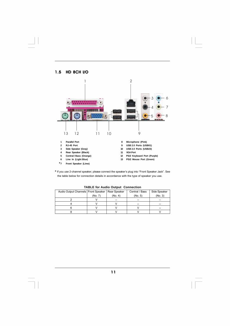
1.51.51.51.51.5 HD 8CH I/OHD 8CH I/OHD 8CH I/OHD 8CH I/OHD 8CH I/O
1 Parallel Port 8 Microphone (Pink)2 RJ-45 Port 9 USB 2.0 Ports (USB01)3 Side Speaker (Gray) 10 USB 2.0 Ports (USB23)4 Rear Speaker (Black) 11 VGA Port5 Central / Bass (Orange) 12 PS/2 Keyboard Port (Purple)6 Line In (Light Blue) 13 PS/2 Mouse Port (Green)
*7 Front Speaker (Lime)
* If you use 2-channel speaker, please connect the speaker’s plug into “Front Speaker Jack”. See the table below for connection details in accordance with the type of speaker you use.
TABLE for Audio Output ConnectionAudio Output Channels Front Speaker Rear Speaker Central / Bass Side Speaker
(No. 7) (No. 4) (No. 5) (No. 3)2 V -- -- --4 V V -- --6 V V V --8 V V V V

1 21 21 21 21 2
2.2.2.2.2. InstallationInstallationInstallationInstallationInstallationK8NF6P-VSTA is a Micro ATX form factor (9.6-in x 8.2-in, 24.4 cm x 20.8 cm)motherboard. Before you install the motherboard, study the configuration of yourchassis to ensure that the motherboard fits into it.
Pre-installation PrecautionsPre-installation PrecautionsPre-installation PrecautionsPre-installation PrecautionsPre-installation PrecautionsTake note of the following precautions before you install motherboardcomponents or change any motherboard settings.
Before you install or remove any component, ensure that thepower is switched off or the power cord is detached from thepower supply. Failure to do so may cause severe damage to themotherboard, peripherals, and/or components.
1. Unplug the power cord from the wall socket before touching anycomponent.
2. To avoid damaging the motherboard components due to staticelectricity, NEVER place your motherboard directly on the carpet orthe like. Also remember to use a grounded wrist strap or touch asafety grounded object before you handle components.
3. Hold components by the edges and do not touch the ICs.4. Whenever you uninstall any component, place it on a grounded anti-
static pad or in the bag that comes with the component.5. When placing screws into the screw holes to secure the motherboard
to the chassis, please do not over-tighten the screws! Doing so maydamage the motherboard.
1 31 31 31 31 3
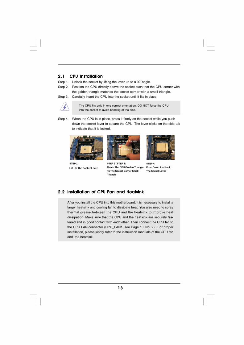
2.12.12.12.12.1 CPU InstallationCPU InstallationCPU InstallationCPU InstallationCPU InstallationStep 1. Unlock the socket by lifting the lever up to a 90o angle.Step 2. Position the CPU directly above the socket such that the CPU corner with
the golden triangle matches the socket corner with a small triangle.Step 3. Carefully insert the CPU into the socket until it fits in place.
The CPU fits only in one correct orientation. DO NOT force the CPUinto the socket to avoid bending of the pins.
Step 4. When the CPU is in place, press it firmly on the socket while you pushdown the socket lever to secure the CPU. The lever clicks on the side tabto indicate that it is locked.
2.22.22.22.22.2 Installation of CPU Fan and HeatsinkInstallation of CPU Fan and HeatsinkInstallation of CPU Fan and HeatsinkInstallation of CPU Fan and HeatsinkInstallation of CPU Fan and Heatsink
After you install the CPU into this motherboard, it is necessary to install alarger heatsink and cooling fan to dissipate heat. You also need to spraythermal grease between the CPU and the heatsink to improve heatdissipation. Make sure that the CPU and the heatsink are securely fas-tened and in good contact with each other. Then connect the CPU fan tothe CPU FAN connector (CPU_FAN1, see Page 10, No. 2). For properinstallation, please kindly refer to the instruction manuals of the CPU fanand the heatsink.
STEP 1:
Lift Up The Socket Lever
STEP 2 / STEP 3:Match The CPU Golden TriangleTo The Socket Corner SmallTriangle
STEP 4:Push Down And LockThe Socket Lever
Lever 90° Up
CPU Golden Triangle
Socket Corner Small Triangle
1 41 41 41 41 4
notch
break
notch
break
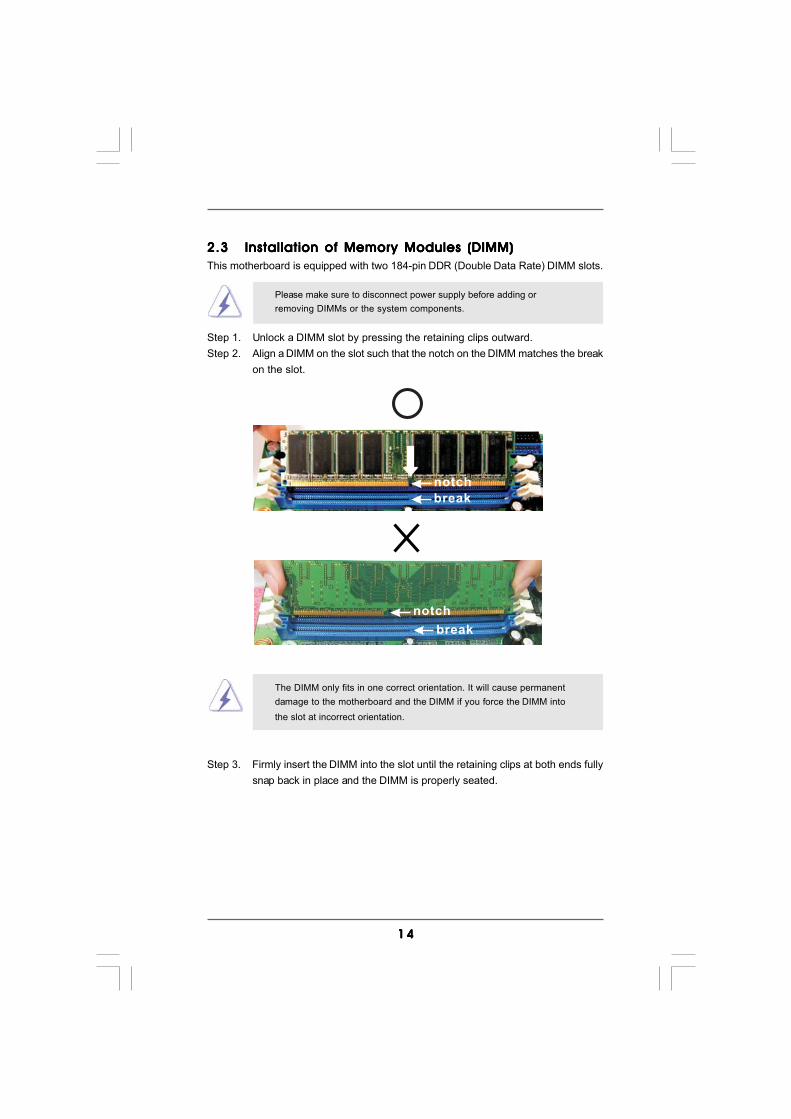
2.32.32.32.32.3 Installation of Memory Modules (DIMM)Installation of Memory Modules (DIMM)Installation of Memory Modules (DIMM)Installation of Memory Modules (DIMM)Installation of Memory Modules (DIMM)This motherboard is equipped with two 184-pin DDR (Double Data Rate) DIMM slots.
Please make sure to disconnect power supply before adding orremoving DIMMs or the system components.
Step 1. Unlock a DIMM slot by pressing the retaining clips outward.Step 2. Align a DIMM on the slot such that the notch on the DIMM matches the break
on the slot.
The DIMM only fits in one correct orientation. It will cause permanentdamage to the motherboard and the DIMM if you force the DIMM intothe slot at incorrect orientation.
Step 3. Firmly insert the DIMM into the slot until the retaining clips at both ends fullysnap back in place and the DIMM is properly seated.
1 51 51 51 51 5
2.42.42.42.42.4 Expansion Slots (PCI, HDMR and PCI Express Slots)Expansion Slots (PCI, HDMR and PCI Express Slots)Expansion Slots (PCI, HDMR and PCI Express Slots)Expansion Slots (PCI, HDMR and PCI Express Slots)Expansion Slots (PCI, HDMR and PCI Express Slots)There are 2 PCI slots, 1 HDMR slot and 2 PCI Express slots on this motherboard.PCI slots: PCI slots are used to install expansion cards that have the 32-bit PCI
interface.HDMR slot: HDMR slot is used to insert a HDMR card with v.92 Modem
functionality. The HDMR slot is shared with PCIE2 slot; you can only choose either PCIE2 slot or HDMR slot to use.
PCIE Slots: PCIE1 (PCIE x16 slot) is used for PCI Express cards with x16 lane width graphics cards.
PCIE2 (PCIE x1 slot) is used for PCI Express cards with x1 lane width cards, such as Gigabit LAN card, SATA2 card, etc.
Installing an expansion cardInstalling an expansion cardInstalling an expansion cardInstalling an expansion cardInstalling an expansion cardStep 1. Before installing the expansion card, please make sure that the power
supply is switched off or the power cord is unplugged. Please read thedocumentation of the expansion card and make necessary hardwaresettings for the card before you start the installation.
Step 2. Remove the bracket facing the slot that you intend to use. Keep the screwsfor later use.
Step 3. Align the card connector with the slot and press firmly until the card iscompletely seated on the slot.
Step 4. Fasten the card to the chassis with screws.
1 61 61 61 61 6
2.5 Easy Multi Monitor Feature2.5 Easy Multi Monitor Feature2.5 Easy Multi Monitor Feature2.5 Easy Multi Monitor Feature2.5 Easy Multi Monitor FeatureThis motherboard supports Multi Monitor upgrade. With the internal onboard VGAand the external add-on PCI Express VGA card, you can easily enjoy the benefitsof Multi Monitor feature. Please refer to the following steps to set up a multimonitor environment:1. Install the NVIDIA® PCI Express VGA card to PCIE1 (PCIE x16 slot). Please refer to page 15 for proper expansion card installation procedures for details.2. Connect the D-Sub input monitor cable to the VGA/D-Sub port on the I/O panel of this motherboard. Connect another D-Sub input monitor cable to the VGA/D-Sub connector of the add-on PCI Express VGA card. Connect the DVI-D input monitor cable to the VGA/DVI-D connector of the add-on PCI Express VGA card.3. Boot your system. Press <F2> to enter BIOS setup. Enter “Share Memory” option to adjust the memory capability to [16MB], [32MB], [64MB], [128MB], or [256MB] to enable the function of onboard VGA/D-sub. Please make sure that the value you select is less than the total capability of the system memory. If you do not adjust the BIOS setup, the default value of “Share Memory”, [Auto], will disable onboard VGA/D-Sub function when the add-on VGA card is inserted to this motherboard.4. Install the onboard VGA driver to your system. If you have installed the onboard VGA driver already, there is no need to install it again.5. Set up a multi-monitor display. Right click the desktop, choose “Properties”, and select the “Settings” tab so that you can adjust the parameters of the multi- monitor according to the steps below. (The item names and operation procedures described in this step are under Windows® XP environment. If you install other Windows® OS, the item names and operation procedures may be similar.) A. Click the “Identify” button to display a large number on each monitor. B. Right-click the display icon in the Display Properties dialog that you wish to be your primary monitor, and then select “Primary”. When you use multiple monitors with your card, one monitor will always be Primary, and all additional monitors will be designated as Secondary. C. Select the display icon identified by the number 2. D. Click “Extend my Windows desktop onto this monitor”. E. Right-click the display icon and select “Attached”, if necessary. F. Set the “Screen Resolution” and “Color Quality” as appropriate for the second monitor. Click “Apply” or “OK” to apply these new values. G. Repeat steps C through E for the diaplay icon identified by the number one, two, and three.
1 71 71 71 71 7
+5V
1_2
+5VSB
2_3
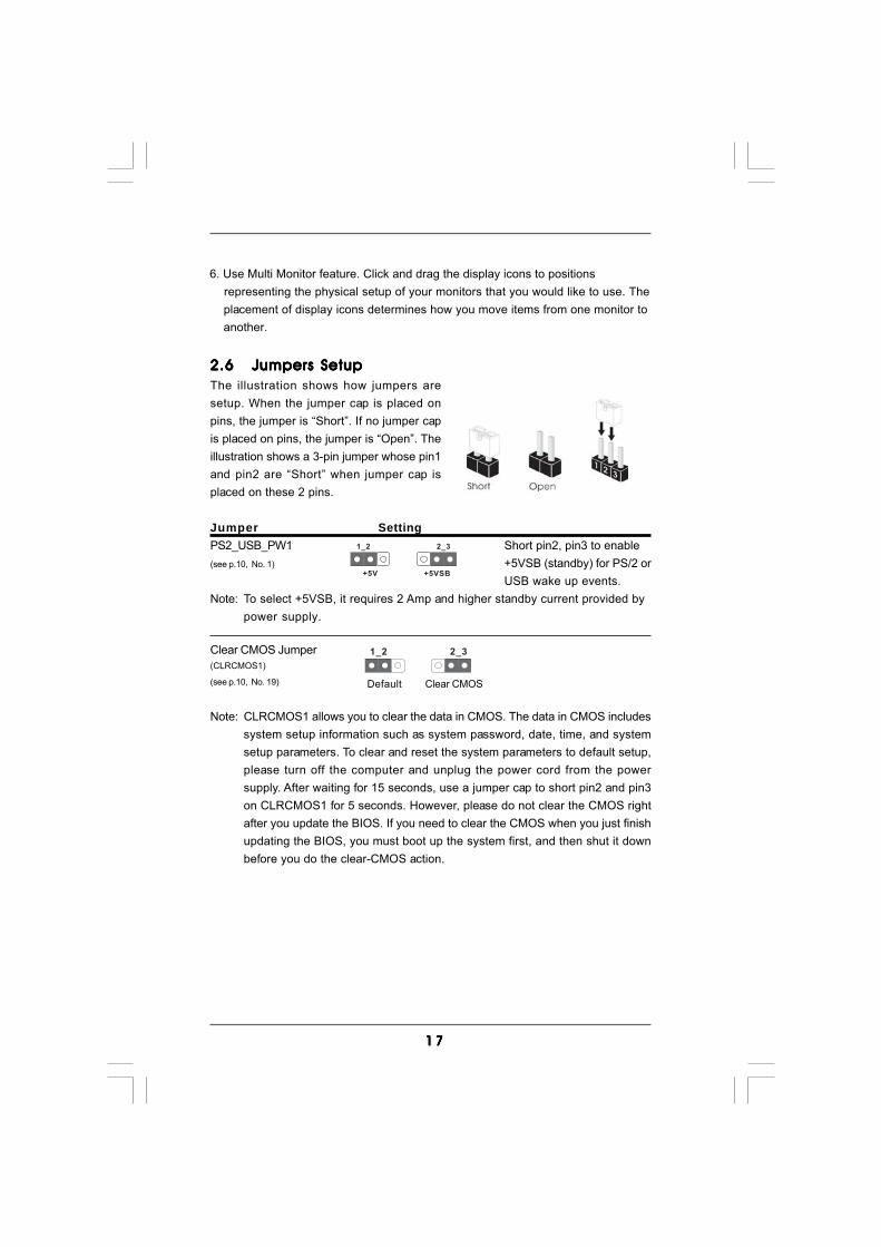
2.62.62.62.62.6 Jumpers SetupJumpers SetupJumpers SetupJumpers SetupJumpers SetupThe illustration shows how jumpers aresetup. When the jumper cap is placed onpins, the jumper is “Short”. If no jumper capis placed on pins, the jumper is “Open”. Theillustration shows a 3-pin jumper whose pin1and pin2 are “Short” when jumper cap isplaced on these 2 pins.
Jumper SettingPS2_USB_PW1 Short pin2, pin3 to enable(see p.10, No. 1) +5VSB (standby) for PS/2 or
USB wake up events.Note: To select +5VSB, it requires 2 Amp and higher standby current provided by
power supply.
Clear CMOS Jumper(CLRCMOS1)
(see p.10, No. 19)
Note: CLRCMOS1 allows you to clear the data in CMOS. The data in CMOS includessystem setup information such as system password, date, time, and systemsetup parameters. To clear and reset the system parameters to default setup,please turn off the computer and unplug the power cord from the powersupply. After waiting for 15 seconds, use a jumper cap to short pin2 and pin3on CLRCMOS1 for 5 seconds. However, please do not clear the CMOS rightafter you update the BIOS. If you need to clear the CMOS when you just finishupdating the BIOS, you must boot up the system first, and then shut it downbefore you do the clear-CMOS action.
Clear CMOS
2_31_2
Default
6. Use Multi Monitor feature. Click and drag the display icons to positions representing the physical setup of your monitors that you would like to use. The placement of display icons determines how you move items from one monitor to another.
1 81 81 81 81 8
FLOPPY1Pin1
the red-striped side to Pin1
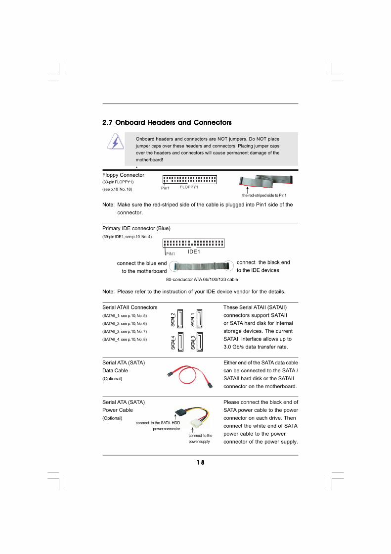
2.7 Onboard Headers and Connectors2.7 Onboard Headers and Connectors2.7 Onboard Headers and Connectors2.7 Onboard Headers and Connectors2.7 Onboard Headers and Connectors
Onboard headers and connectors are NOT jumpers. Do NOT placejumper caps over these headers and connectors. Placing jumper capsover the headers and connectors will cause permanent damage of themotherboard!•
Floppy Connector(33-pin FLOPPY1)
(see p.10 No. 18)
Note: Make sure the red-striped side of the cable is plugged into Pin1 side of theconnector.
Primary IDE connector (Blue)(39-pin IDE1, see p.10 No. 4)
Note: Please refer to the instruction of your IDE device vendor for the details.
Serial ATAII Connectors These Serial ATAII (SATAII)(SATAII_1: see p.10, No. 5) connectors support SATAII(SATAII_2: see p.10, No. 6) or SATA hard disk for internal(SATAII_3: see p.10, No. 7) storage devices. The current(SATAII_4: see p.10, No. 8) SATAII interface allows up to
3.0 Gb/s data transfer rate.
Serial ATA (SATA) Either end of the SATA data cableData Cable can be connected to the SATA /(Optional) SATAII hard disk or the SATAII
connector on the motherboard.
Serial ATA (SATA) Please connect the black end ofPower Cable SATA power cable to the power(Optional) connector on each drive. Then
connect the white end of SATApower cable to the powerconnector of the power supply.
connect the black endto the IDE devices
connect the blue endto the motherboard
IDE1PIN1
80-conductor ATA 66/100/133 cable
connect to the SATA HDDpower connector
connect to thepower supply
SATA
II_1
SATA
II_2
SATA
II_3
SATA
II_4

1 91 91 91 91 9
1. High Definition Audio supports Jack Sensing, but the panel wire on the chassis must support HDA to function correctly. Please follow the instruction in our manual and chassis manual to install your system.
2. If you use AC’97 audio panel, please install it to the front panel audio header as below: A. Connect Mic_IN (MIC) to MIC2_L. B. Connect Audio_R (RIN) to OUT2_R and Audio_L (LIN) to OUT2_L.
C. Connect Ground (GND) to Ground (GND).
USB 2.0 Headers Besides four default USB 2.0(9-pin USB6_7) ports on the I/O panel, there are(see p.10 No. 11) three USB 2.0 headers on this
motherboard. Each USB 2.0header can support two USB2.0 ports.
(9-pin USB8_9)(see p.10 No. 12)
(9-pin USB4_5)(see p.10 No. 13)
Infrared Module Header This header supports an(5-pin IR1) optional wireless transmitting(see p.10 No. 17) and receiving infrared module.
Internal Audio Connectors This connector allows you(4-pin CD1) to receive stereo audio input(CD1: see p.10 No. 27) from sound sources such as
a CD-ROM, DVD-ROM, TVtuner card, or MPEG card.
Front Panel Audio Header This is an interface for the front(9-pin HD_AUDIO1) panel audio cable that allows(see p.10, No. 23) convenient connection and
control of audio devices.
1
IRTX
IRRXGND
+5VSBDUMMY
J_SENSE
OUT2_L
1
MIC_RETPRESENCE#
GND
OUT2_RMIC2_R
MIC2_L
OUT_RET
CD1
CD-L
GNDGND
CD-R
USB_PWR
USB_PWR
P+7P-7
P+6P-6
GND
GND
DUMMY
1
USB_PWR
USB_PWR
P+5P-5
P+4P-4
GND
GND
DUMMY
1
1
USB_PWRP-8
GND
DUMMY
USB_PWR
P+8
GND
P-9P+9
2 02 02 02 02 0
+5V
DUMMYDUMMY
SPEAKER
1
GND
PWRBTN#PLED-
PLED+
DUMMYRESET#
GND
HDLED+HDLED-
1
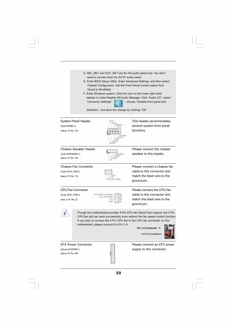
System Panel Header This header accommodates(9-pin PANEL1) several system front panel(see p.10 No. 15) functions.
Chassis Speaker Header Please connect the chassis(4-pin SPEAKER 1) speaker to this header.(see p.10 No. 16)
Chassis Fan Connector Please connect a chassis fan(3-pin CHA_FAN1) cable to this connector and(see p.10 No. 14) match the black wire to the
ground pin.
CPU Fan Connector Please connect the CPU fan(4-pin CPU_FAN1) cable to this connector and(see p.10 No. 2) match the black wire to the
ground pin.
Though this motherboard provides 4-Pin CPU fan (Quiet Fan) support, the 3-Pin CPU fan still can work successfully even without the fan speed control function. If you plan to connect the 3-Pin CPU fan to the CPU fan connector on this motherboard, please connect it to Pin 1-3.
3-Pin Fan Installation
Pin 1-3 Connected
ATX Power Connector Please connect an ATX power(20-pin ATXPWR1) supply to this connector.(see p.10 No. 28)
GND
+12V
CPU_FAN_SPEED
FAN_SPEED_CONTROL
GND+12V
CHA_FAN_SPEED
4321
D. MIC_RET and OUT_RET are for HD audio panel only. You don’t need to connect them for AC’97 audio panel. E. Enter BIOS Setup Utility. Enter Advanced Settings, and then select
Chipset Configuration. Set the Front Panel Control option from [Auto] to [Enabled]. F. Enter Windows system. Click the icon on the lower right hand taskbar to enter Realtek HD Audio Manager. Click “Audio I/O”, select “Connector Settings” , choose “Disable front panel jack
detection”, and save the change by clicking “OK”.
2 12 12 12 12 1
MIDI_OUT
JAB2
JBYJBB2
MIDI_IN
+5V
JAYGND
GND
1
JAXJAB1
+5V
JBXJBB1
+5V
CCTS#1DDSR#1
DDTR#1RRXD1
DDCD#1TTXD1
GNDRRTS#1
RRI#1
1
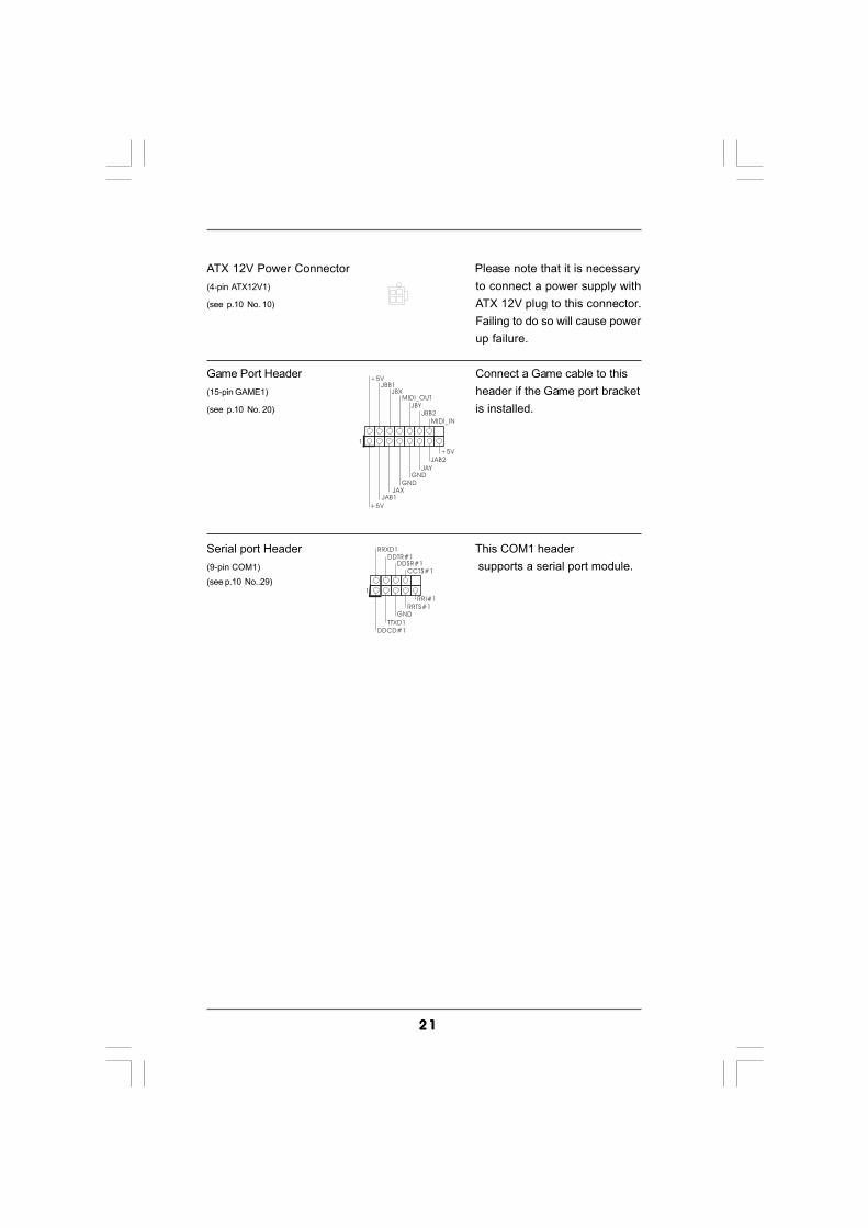
ATX 12V Power Connector Please note that it is necessary(4-pin ATX12V1) to connect a power supply with(see p.10 No. 10) ATX 12V plug to this connector.
Failing to do so will cause powerup failure.
Game Port Header Connect a Game cable to this(15-pin GAME1) header if the Game port bracket(see p.10 No. 20) is installed.
Serial port Header This COM1 header(9-pin COM1) supports a serial port module.(see p.10 No..29)

2 22 22 22 22 2
2.82.82.82.82.8 SASASASASATTTTTAII Hard Disk Setup GuideAII Hard Disk Setup GuideAII Hard Disk Setup GuideAII Hard Disk Setup GuideAII Hard Disk Setup GuideBefore installing SATAII hard disk to your computer, please carefully read belowSATAII hard disk setup guide. Some default setting of SATAII hard disks may notbe at SATAII mode, which operate with the best performance. In order to enableSATAII function, please follow the below instruction with different vendors to
correctly adjust your SATAII hard disk to SATAII mode in advance; otherwise, yourSATAII hard disk may fail to run at SATAII mode.
Western Digital
If pin 5 and pin 6 are shorted, SATA 1.5Gb/s will be enabled.On the other hand, if you want to enable SATAII 3.0Gb/s, please remove thejumpers from pin 5 and pin 6.
SAMSUNG
If pin 3 and pin 4 are shorted, SATA 1.5Gb/s will be enabled.On the other hand, if you want to enable SATAII 3.0Gb/s, please remove thejumpers from pin 3 and pin 4.
HITACHIPlease use the Feature Tool, a DOS-bootable tool, for changing various ATAfeatures. Please visit HITACHI’s website for details:
http://www.hitachigst.com/hdd/support/download.htm
1357
2468
1357
2468
The above examples are just for your reference. For different SATAII harddisk products of different vendors, the jumper pin setting methods may notbe the same. Please visit the vendors’ website for the updates.
2 32 32 32 32 3
2.92.92.92.92.9 Serial ASerial ASerial ASerial ASerial ATTTTTA (SAA (SAA (SAA (SAA (SATTTTTA) / Serial AA) / Serial AA) / Serial AA) / Serial AA) / Serial ATTTTTAII (SAAII (SAAII (SAAII (SAAII (SATTTTTAII) Hard DisksAII) Hard DisksAII) Hard DisksAII) Hard DisksAII) Hard Disks
InstallationInstallationInstallationInstallationInstallationThis motherboard adopts NVIDIA® GeForce 6100 / nForce 430 or GeForce 6150SE/ nForce 430 chipset that supports Serial ATA (SATA) / Serial ATAII (SATAII) harddisks and RAID functions. You may install SATA / SATAII hard disks on thismotherboard for internal storage devices. This section will guide you to install theSATA / SATAII hard disks.
STEP 1: Install the SATA / SATAII hard disks into the drive bays of your chassis.STEP 2: Connect the SATA power cable to the SATA / SATAII hard disk.STEP 3: Connect one end of the SATA data cable to the motherboard’s SATAII
connector.STEP 4: Connect the other end of the SATA data cable to the SATA / SATAII hard
disk.
2.102.102.102.102.10 Hot Plug and Hot Swap FHot Plug and Hot Swap FHot Plug and Hot Swap FHot Plug and Hot Swap FHot Plug and Hot Swap Functions for SAunctions for SAunctions for SAunctions for SAunctions for SATTTTTA / SAA / SAA / SAA / SAA / SATTTTTAIIAIIAIIAIIAII
HDDsHDDsHDDsHDDsHDDsThis motherboard supports Hot Plug and Hot Swap functions for SATA / SATAIIDevices.
NOTEWhat is Hot Plug Function?If the SATA / SATAII HDDs are NOT set for RAID configuration, it iscalled “Hot Plug” for the action to insert and remove the SATA / SATAIIHDDs while the system is still power-on and in working condition.However, please note that it cannot perform Hot Plug if the OS hasbeen installed into the SATA / SATAII HDD.
What is Hot Swap Function?If SATA / SATAII HDDs are built as RAID1 then it is called “Hot Swap”for the action to insert and remove the SATA / SATAII HDDs while thesystem is still power-on and in working condition.
2.112.112.112.112.11 Driver Installation GuideDriver Installation GuideDriver Installation GuideDriver Installation GuideDriver Installation GuideTo install the drivers to your system, please insert the support CD to your opticaldrive first. Then, the drivers compatible to your system can be auto-detected andlisted on the support CD driver page. Please follow the order from up to bottomside to install those required drivers. Therefore, the drivers you install can workproperly.

2 42 42 42 42 4
2.122.122.122.122.12 HDMR Card and Driver Installation HDMR Card and Driver Installation HDMR Card and Driver Installation HDMR Card and Driver Installation HDMR Card and Driver InstallationIf you do not insert HDMR card to this motherboard, and you finish installing alldrivers to your system now, but in the future, you plan to use HDMR card functionon this motherboard, please follow the steps below then.1. Insert HDMR card to HDMR slot on this motherboard. Please make sure that the HDMR card is completely seated on the slot.2. Install HDMR card driver from our support CD to your system.3. Reboot your system.
2.132.132.132.132.13 Installing WindowsInstalling WindowsInstalling WindowsInstalling WindowsInstalling Windows® 2000 / XP / XP 64-bit / Vista 2000 / XP / XP 64-bit / Vista 2000 / XP / XP 64-bit / Vista 2000 / XP / XP 64-bit / Vista 2000 / XP / XP 64-bit / VistaTMTMTMTMTM
/ Vista/ Vista/ Vista/ Vista/ VistaTMTMTMTMTM 64-bit Without RAID Functions 64-bit Without RAID Functions 64-bit Without RAID Functions 64-bit Without RAID Functions 64-bit Without RAID Functions
2.142.142.142.142.14 Installing WindowsInstalling WindowsInstalling WindowsInstalling WindowsInstalling Windows® 2000 / XP / XP 64-bit / Vista 2000 / XP / XP 64-bit / Vista 2000 / XP / XP 64-bit / Vista 2000 / XP / XP 64-bit / Vista 2000 / XP / XP 64-bit / VistaTMTMTMTMTM
/ Vista/ Vista/ Vista/ Vista/ VistaTMTMTMTMTM 64-bit With RAID Functions 64-bit With RAID Functions 64-bit With RAID Functions 64-bit With RAID Functions 64-bit With RAID FunctionsIf you want to install Windows® 2000, Windows® XP, Windows® XP 64-bit, Windows®
VistaTM or Windows® VistaTM 64-bit OS on your SATA / SATAII HDDs with RAIDfunctions, please follow below procedures according to the OS you install.
The installation procedures for Windows® VistaTM / VistaTM 64-bit are subject tochange. Please visit our website for the updates of Windows® VistaTM / VistaTM 64-bitdriver and related information in the future.
If you just want to install Windows® 2000, Windows® XP, Windows® XP 64-bit,Windows® VistaTM or Windows® VistaTM 64-bit on your SATA / SATAII HDDs withoutRAID functions, you don’t have to make a SATA / SATAII driver diskette. Besides,there is no need for you to change the BIOS setting. You can start to install Windows®
2000, Windows® XP, Windows® XP 64-bit, Windows® VistaTM or Windows® VistaTM
64-bit on your system directly.
1. The installation procedures for Windows® VistaTM / VistaTM 64-bit are subject to change. Please visit our website for the updates of Windows® VistaTM / VistaTM
64-bit driver and related information in the future.2. Before installing Windows® 2000 to your system, your Windows® 2000 optical disk is supposed to include SP4. If there is no SP4 included in your disk, please visit the below website for proper procedures of making a SP4 disk: http://www.microsoft.com/Windows2000/downloads/servicepacks/sp4/spdeploy. htm#the_integrated_installation_fmay
2 52 52 52 52 5
2.14.1 Installing Windows2.14.1 Installing Windows2.14.1 Installing Windows2.14.1 Installing Windows2.14.1 Installing Windows® 2000 / XP / XP 64-bit With RAID 2000 / XP / XP 64-bit With RAID 2000 / XP / XP 64-bit With RAID 2000 / XP / XP 64-bit With RAID 2000 / XP / XP 64-bit With RAID
Functions Functions Functions Functions FunctionsIf you want to install Windows® 2000, Windows® XP or Windows® XP 64-bit on yourSATA / SATAII HDDs with RAID functions, please follow below steps.
STEP 1: Make a SATA / SATAII Driver Diskette.A. Insert the ASRock Support CD into your optical drive to boot your system.B. During POST at the beginning of system boot-up, press <F11> key, and
then a window for boot devices selection appears. Please select CD-ROM as the boot device.
C. When you see the message on the screen, “Generate Serial ATA driverdiskette [YN]?”, press <Y>.
D. Then you will see these messages,Please insert a blankformatted diskette into floppydrive A:press any key to start
Please insert a floppy diskette into the floppy drive, and press any key.E. The system will start to format the floppy diskette and copy SATA /
SATAII drivers into the floppy diskette.STEP 2: Set Up BIOS.A. Enter BIOS SETUP UTILITY Advanced screen IDE Configuration.B. Set the “SATA Operation Mode” option to [RAID].STEP 3: Use “RAID Installation Guide” to set RAID configuration.Before you start to configure RAID function, you need to check the RAID installationguide in the Support CD for proper configuration. Please refer to the BIOS RAIDinstallation guide in the following path in the Support CD:.. \ RAID Installation GuideSTEP 4: Install Windows® 2000 / Windows® XP / Windows® XP 64-bit OS on
your system.After step1, 2, 3, you can start to install Windows® 2000 / Windows® XP / Windows®
XP 64-bit OS on your system. At the beginning of Windows® setup, press F6 to installa third-party RAID driver. When prompted, insert the SATA / SATAII driver diskettecontaining the NVIDIA® RAID driver. After reading the floppy disk, the driver will bepresented. Select the driver to install according to the mode you choose and the OSyou install.
NOTE. If you install Windows® 2000 / Windows® XP / Windows® XP 64-bit on IDEHDDs and want to manage (create, convert, delete, or rebuild) RAID functionson SATA / SATAII HDDs, you still need to set up “SATA Operation Mode” to [RAID] inBIOS first. Then, please set the RAID configuration by using the Windows RAIDinstallation guide in the following path in the Support CD:.. \ RAID Installation Guide
2 62 62 62 62 6
2.14.2 Installing Windows2.14.2 Installing Windows2.14.2 Installing Windows2.14.2 Installing Windows2.14.2 Installing Windows® Vista Vista Vista Vista VistaTM TM TM TM TM / Vista/ Vista/ Vista/ Vista/ VistaTMTMTMTMTM 64-bit With 64-bit With 64-bit With 64-bit With 64-bit With
RAID Functions RAID Functions RAID Functions RAID Functions RAID FunctionsIf you want to install Windows® VistaTM or Windows® VistaTM 64-bit on your SATA /SATAII HDDs with RAID functions, please follow below steps.
STEP 1: Set Up BIOS.A. Enter BIOS SETUP UTILITY Advanced screen IDE Configuration.B. Set the “SATA Operation Mode” option to [RAID].STEP 2: Use “RAID Installation Guide” to set RAID configuration.Before you start to configure RAID function, you need to check the RAID installationguide in the Support CD for proper configuration. Please refer to the BIOS RAIDinstallation guide in the following path in the Support CD:.. \ RAID Installation GuideSTEP 3: Install Windows® VistaTM / Windows® VistaTM 64-bit OS on your system.Insert the Windows® VistaTM / Windows® VistaTM 64-bit optical disk into the opticaldrive to boot your system, and follow the instruction to install Windows® VistaTM /Windows® VistaTM 64-bit OS on your system. When you see “Where do you want toinstall Windows?” page, please insert the ASRock Support CD into your optical drive,and click the “Load Driver” button on the left on the bottom to load the NVIDIA® RAIDdrivers. NVIDIA® RAID drivers are in the following path in our Support CD:.. \ I386 \ Vista (For Windows® VistaTM OS).. \ AMD64 \ Vista64 (For Windows® VistaTM 64-bit OS)After that, please insert Windows® VistaTM / Windows® VistaTM 64-bit optical disk intothe optical drive again to continue the installation.
NOTE1. If you install Windows® VistaTM / Windows® VistaTM 64-bit on IDE HDDs andwant to manage (create, convert, delete, or rebuild) RAID functions on SATA /SATAII HDDs, you still need to set up “SATA Operation Mode” to [RAID] in BIOSfirst. Then, please set the RAID configuration by using the Windows RAIDinstallation guide in the following path in the Support CD:.. \ RAID Installation Guide
NOTE2. Currently, NVIDIA® RAID driver cannot support Hot Swap function to rebuildRAID 5 and RAID 0+1 under Windows® VistaTM / VistaTM 64-bit. It is recom-mended to rebuild RAID 5 and RAID 0+1 under RAID ROM. Please press <F10>when the system boots to enter RAID ROM utility. Please refer to “RAIDInstallation Guide” in the Support CD for details of rebuilding RAID. For theupdated NVIDIA® RAID driver, please visit our website in the future.(http://www.asrock.com)

2 72 72 72 72 7
3.3.3.3.3. BIOS SETUP UTILITYBIOS SETUP UTILITYBIOS SETUP UTILITYBIOS SETUP UTILITYBIOS SETUP UTILITY3.1 Introduction3.1 Introduction3.1 Introduction3.1 Introduction3.1 IntroductionThis section explains how to use the BIOS SETUP UTILITY to configure your system.The Flash Memory on the motherboard stores the BIOS SETUP UTILITY. You may runthe BIOS SETUP UTILITY when you start up the computer. Please press <F2> duringthe Power-On-Self-Test (POST) to enter the BIOS SETUP UTILITY, otherwise, POSTwill continue with its test routines.If you wish to enter the BIOS SETUP UTILITY after POST, restart the system bypressing <Ctl> + <Alt> + <Delete>, or by pressing the reset button on the systemchassis. You may also restart by turning the system off and then back on.
Because the BIOS software is constantly being updated, the followingBIOS setup screens and descriptions are for reference purpose only,and they may not exactly match what you see on your screen.
3.1.13.1.13.1.13.1.13.1.1 BIOS Menu BarBIOS Menu BarBIOS Menu BarBIOS Menu BarBIOS Menu BarThe top of the screen has a menu bar with the following selections:Main To set up the system time/date informationAdvanced To set up the advanced BIOS featuresH/W Monitor To display current hardware statusBoot To set up the default system device to locate and load the
Operating SystemSecurity To set up the security featuresExit To exit the current screen or the BIOS SETUP UTILITYUse < > key or < > key to choose among the selections on the menu bar,and then press <Enter> to get into the sub screen.
2.152.152.152.152.15 Untied Overclocking TUntied Overclocking TUntied Overclocking TUntied Overclocking TUntied Overclocking TechnologyechnologyechnologyechnologyechnologyThis motherboard supports Untied Overclocking Technology, which means duringoverclocking, FSB enjoys better margin due to fixed PCI / PCIE buses. Before youenable Untied Overclocking function, please enter “Overclock Mode” option of BIOSsetup to set the selection from [Auto] to [CPU, PCIE, Async.]. Therefore, CPU FSB isuntied during overclocking, but PCI / PCIE buses are in the fixed mode so that FSB canoperate under a more stable overclocking environment.
Please refer to the warning on page 7 for the possible overclocking risk beforeyou apply Untied Overclocking Technology.

2 82 82 82 82 8
BIOS SETUP UTILITY
Main Advanced H/W Monitor Boot Security Exit
System Overview
System Time
System Date[ :00:09][Tue 02/06/2007]
Use [Enter], [TAB]or [SHIFT-TAB] toselect a field.
Use [+] or [-] toconfigure system Time.
Select ScreenSelect Item
+- Change FieldTab Select FieldF1 General HelpF9 Load DefaultsF10 Save and ExitESC Exit
BIOS VersionProcessor Type
Processor SpeedMicrocode UpdateL1 Cache SizeL2 Cache Size
Total MemoryDDR 1DDR 2
: K8NF6P-VSTA BIOS P1.00: AMD Athlon(tm) 64 Processor 3400+
(64bit supported): 2200 MHz: F7A/3A: 128KB: 512KB
: 256MB with 64MB shared memory: 256MB/166MHz (DDR333): None
v02.54 (C) Copyright 1985-2003, American Megatrends, Inc.
17
3.1.23.1.23.1.23.1.23.1.2 Navigation KeysNavigation KeysNavigation KeysNavigation KeysNavigation KeysPlease check the following table for the function description of each navigationkey.
Navigation Key(s) Function Description / Moves cursor left or right to select Screens / Moves cursor up or down to select items + / - To change option for the selected items<Enter> To bring up the selected screen<F1> To display the General Help Screen<F9> To load optimal default values for all the settings<F10> To save changes and exit the BIOS SETUP UTILITY<ESC> To jump to the Exit Screen or exit the current screen
3.23.23.23.23.2 Main ScreenMain ScreenMain ScreenMain ScreenMain ScreenWhen you enter the BIOS SETUP UTILITY, the Main screen will appear and displaythe system overview.
System Time [Hour:Minute:Second]Use this item to specify the system time.
System Date [Day Month/Date/Year]Use this item to specify the system date.
2 92 92 92 92 9
BIOS SETUP UTILITY
CPU Configuration
Select ScreenSelect Item
+- Change OptionF1 General HelpF9 Load DefaultsF10 Save and ExitESC Exit
v02.54 (C) Copyright 1985-2003, American Megatrends, Inc.
Advanced
Select ScreenSelect Item
+- Change OptionF1 General HelpF9 Load DefaultsF10 Save and ExitESC Exit
CPU Frequency (MHz)PCIE Frequency (MHz)
Overclock Mode[200][100]
[Auto]
CPU/LDT Spread SpectrumPCIESATACool' n' Quiet
Spread SpectrumSpread Spectrum
[0.75% Hershey][Enabled][Enabled][Auto]
Processor Maximum MultiplierProcessor Maximum Voltage
Memory ClockFlexibility OptionCAS LatencyTRASTRPTRCDTRRD
[Auto]
[Auto][Auto][Auto][Auto]
[Disabled][Auto]
x111.550 V
Boot Failure Guard [Enabled]
Multiplier/Voltage Change [Auto]
If AUTO, multiplier andvoltage will be left at therated frequency/voltage. IfManual,
will be set basedon User Selection in Setup.
multiplier andvoltage
BIOS SETUP UTILITY
Main H/W Monitor Boot Security Exit
Advanced Settings
WARNING : Setting wrong values in below sectionsmay cause system to malfunction.
Options for CPU
Select ScreenSelect Item
Enter Go to Sub ScreenF1 General HelpF9 Load DefaultsF10 Save and ExitESC Exit
v02.54 (C) Copyright 1985-2003, American Megatrends, Inc.
Advanced
CPU ConfigurationChipset ConfigurationACPI ConfigurationIDE ConfigurationPCIPnP ConfigurationFloppy ConfigurationSuperIOUSB Configuration
Configuration
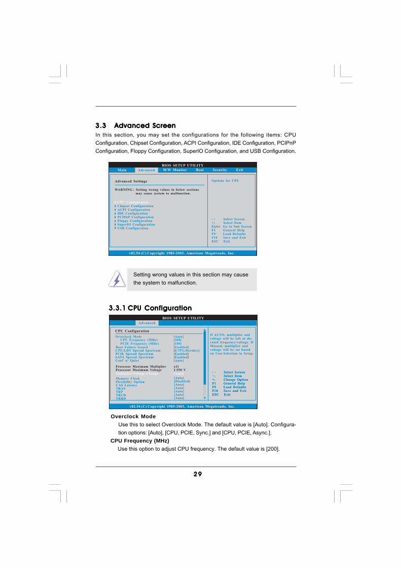
3.33.33.33.33.3 Advanced ScreenAdvanced ScreenAdvanced ScreenAdvanced ScreenAdvanced ScreenIn this section, you may set the configurations for the following items: CPUConfiguration, Chipset Configuration, ACPI Configuration, IDE Configuration, PCIPnPConfiguration, Floppy Configuration, SuperIO Configuration, and USB Configuration.
Setting wrong values in this section may causethe system to malfunction.
3.3.13.3.13.3.13.3.13.3.1 CPU ConfigurationCPU ConfigurationCPU ConfigurationCPU ConfigurationCPU Configuration
Overclock ModeUse this to select Overclock Mode. The default value is [Auto]. Configura-tion options: [Auto], [CPU, PCIE, Sync.] and [CPU, PCIE, Async.].
CPU Frequency (MHz) Use this option to adjust CPU frequency. The default value is [200].

3 03 03 03 03 0
PCIE Frequency (MHz) Use this option to adjust PCIE frequency. The default value is [100]. Boot Failure Guard Enable or disable the feature of Boot Failure Guard.
CPU/LDT Spread SpectrumThis feature will be set to [0.75% Hershey] as default. Configurationoptions: [Disabled], [0.5% Hershey], [0.75% Hershey], [0.5% Triangular],and [0.75% Triangular].
PCIE Spread SpectrumThis feature will be set to [Enabled] as default. Configurationoptions: [Disabled], and [Enabled].
SATA Spread SpectrumThis feature will be set to [Enabled] as default. Configurationoptions: [Disabled], and [Enabled].
Cool ‘n’ QuietUse this item to enable or disable AMD’s Cool ‘n’ QuietTM technology. Thedefault value is [Auto]. Configuration options: [Auto], [Enabled] and[Disabled]. If you install Windows® VistaTM and want to enable this function,please set this item to [Enabled]. Please note that enabling this function mayreduce CPU voltage and memory frequency, and lead to system stability orcompatibility issue with some memory modules or power supplies. Pleaseset this item to [Disable] if above issue occurs.
Processor Maximum MultiplierIt will display Processor Maximum Multiplier for reference.
Processor Maximum VoltageIt will display Processor Maximum Voltage for reference.
Multiplier/Voltage ChangeThis item is set to [Auto] by default. If it is set to [Manual], you may adjust thevalue of Processor Multiplier and Processor Voltage. However, it is recom-mended to keep the default value for system stability.
BIOS SETUP UTILITY
BIOS SETUP UTILITY
CPU Configuration
Select ScreenSelect Item
+- Change OptionF1 General HelpF9 Load DefaultsF10 Save and ExitESC Exit
v02.54 (C) Copyright 1985-2003, American Megatrends, Inc.
Advanced
Select ScreenSelect Item
+- Change OptionF1 General HelpF9 Load DefaultsF10 Save and ExitESC Exit
CPU Frequency (MHz)PCIE Frequency (MHz)
Overclock Mode[200][100]
[Auto]
CPU/LDT Spread SpectrumPCIESATACool' n' Quiet
Spread SpectrumSpread Spectrum
[0.75% Hershey][Enabled][Enabled][Auto]
Processor Maximum MultiplierProcessor Maximum Voltage
Memory ClockFlexibility OptionCAS LatencyTRAS
[Auto]
[Auto]
[Disabled][Auto]
x111.550 V
Boot Failure Guard [Enabled]
Multiplier/Voltage Change [Manual]
If AUTO, multiplier andvoltage will be left at therated frequency/voltage. IfManual,
will be set basedon User Selection in Setup.
multiplier andvoltage
BIOS SETUP UTILITY
Processor MultiplierProcessor Voltage
[x8][1.500V]

3 13 13 13 13 1
Processor MultiplierThis item will show when “Multiplier/Voltage Change” is set to [Manual];otherwise, it will be hidden. The range of the value depends on the CPUyou adopt on this motherboard. However, for system stability, it is notrecommended to adjust the value of this item.
Processor VoltageThis item will show when “Multiplier/Voltage Change” is set to [Manual];otherwise, it will be hidden. The range of the value depends on the CPUyou adopt on this motherboard. However, for safety and system stability,it is not recommended to adjust the value of this item.
Memory ClockThis item can be set by the code using [Auto]. You can set one of thestandard values as listed: [133 MHz (DDR266)], [166 MHz (DDR333)],[200 MHz (DDR400)].
Flexibility OptionThe default value of this option is [Disabled]. It will allow better tolerance formemory compatibility when it is set to [Enabled].
CAS LatencyUse this item to adjust the means of memory accessing. Configurationoptions: [Auto], [2.0], [3.0], and [2.5]. The default value is [Auto].
TRASUse this to adjust TRAS values. Configuration options: [Auto], [5CLK], [6CLK],[7CLK], [8CLK], [9CLK], [10CLK], [11CLK], [12CLK], [13CLK], [14CLK], and[15CLK]. The default value is [Auto].
TRPUse this to adjust TRP values. Configuration options: [Auto], [2CLK], [3CLK],[4CLK], [5CLK], and [6CLK]. The default value is [Auto].
TRCDUse this to adjust TRCD values. Configuration options: [Auto], [2CLK], [3CLK],[4CLK], [5CLK], and [6CLK]. The default value is [Auto].
TRRDUse this to adjust TRRD values. Configuration options: [Auto], [2T], [3T], and[4T]. The default value is [Auto].
TRCUse this to adjust TRC values. Configuration options: [7T] to [22T]. Thedefault value is [Auto].
TREFUse this to adjust TREF values. Configuration options: [Auto], [15.6us],[7.8us] and [3.9us]. The default value is [Auto].
MA TimingUse this to adjust values for MA timing. Configuration options: [Auto], [2T],[1T]. The default value is [Auto].
Burst LengthBurst length can be set to 8, 4 or 2 beats. 64 Bit Dq must use the 4 beats.
3 23 23 23 23 2
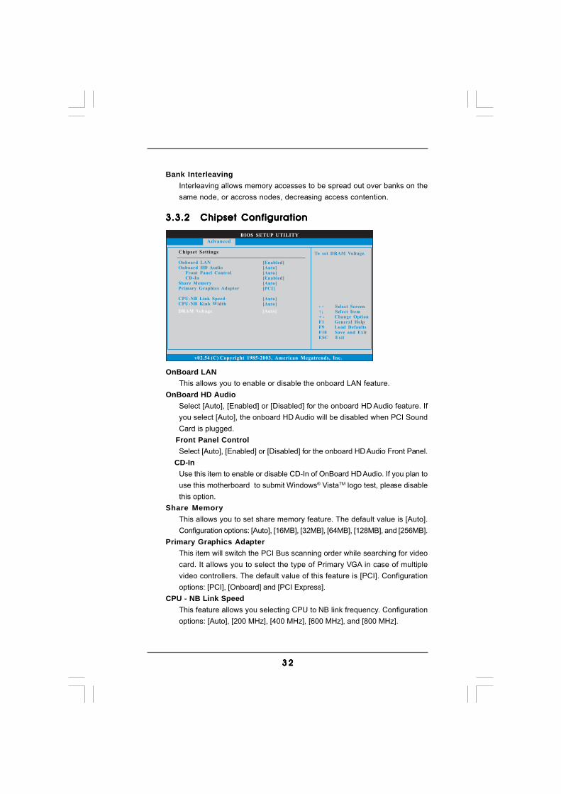
3.3.23.3.23.3.23.3.23.3.2 Chipset ConfigurationChipset ConfigurationChipset ConfigurationChipset ConfigurationChipset Configuration
OnBoard LANThis allows you to enable or disable the onboard LAN feature.
OnBoard HD AudioSelect [Auto], [Enabled] or [Disabled] for the onboard HD Audio feature. Ifyou select [Auto], the onboard HD Audio will be disabled when PCI SoundCard is plugged.
Front Panel ControlSelect [Auto], [Enabled] or [Disabled] for the onboard HD Audio Front Panel.
CD-InUse this item to enable or disable CD-In of OnBoard HD Audio. If you plan touse this motherboard to submit Windows® VistaTM logo test, please disablethis option.
Share MemoryThis allows you to set share memory feature. The default value is [Auto].Configuration options: [Auto], [16MB], [32MB], [64MB], [128MB], and [256MB].
Primary Graphics AdapterThis item will switch the PCI Bus scanning order while searching for videocard. It allows you to select the type of Primary VGA in case of multiplevideo controllers. The default value of this feature is [PCI]. Configurationoptions: [PCI], [Onboard] and [PCI Express].
CPU - NB Link SpeedThis feature allows you selecting CPU to NB link frequency. Configurationoptions: [Auto], [200 MHz], [400 MHz], [600 MHz], and [800 MHz].
BIOS SETUP UTILITY
v02.54 (C) Copyright 1985-2003, American Megatrends, Inc.
Chipset Settings
Onboard LANOnboard HD Audio
Front Panel ControlCD-In
Share MemoryGraphics Adapter
CPU-NB Link SpeedCPU-NB Kink Width
Primary
[Enabled]
[Auto][PCI]
[Auto]
[Auto][Auto]
[Auto]
[Enabled]
Select ScreenSelect Item
+ - Change OptionF1 General Help
F10 Save and ExitESC Exit
F9 Load Defaults
Advanced
DRAM Voltage [Auto]
To set DRAM Voltage.
Bank InterleavingInterleaving allows memory accesses to be spread out over banks on thesame node, or accross nodes, decreasing access contention.
3 33 33 33 33 3
BIOS SETUP UTILITY
ACPI Settings Select auto-detect ordisable the STRfeature.
Select ScreenSelect Item
+- Change OptionF1 General HelpF9 Load DefaultsF10 Save and ExitESC Exit
v02.54 (C) Copyright 1985-2003, American Megatrends, Inc.
Advanced
Suspend To RAM
Repost Video on STR Resume
Restore on AC / Power LossRing-In Power OnPCI Devices Power OnPS / 2 Keyboard Power OnRTC Alarm Power On
ACPI HPET Table
[Auto]
[No]
[Power Off][Disabled][Disabled][Disabled][Disabled]
[Disabled]
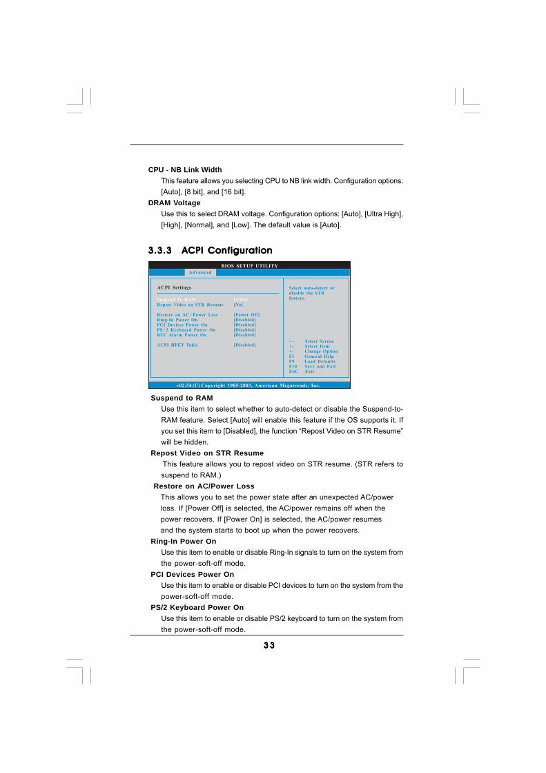
3.3.33.3.33.3.33.3.33.3.3 ACPI ConfigurationACPI ConfigurationACPI ConfigurationACPI ConfigurationACPI Configuration
Suspend to RAMUse this item to select whether to auto-detect or disable the Suspend-to-RAM feature. Select [Auto] will enable this feature if the OS supports it. Ifyou set this item to [Disabled], the function “Repost Video on STR Resume”will be hidden.
Repost Video on STR Resume This feature allows you to repost video on STR resume. (STR refers to
suspend to RAM.) Restore on AC/Power Loss
This allows you to set the power state after an unexpected AC/power loss. If [Power Off] is selected, the AC/power remains off when the power recovers. If [Power On] is selected, the AC/power resumes and the system starts to boot up when the power recovers.
Ring-In Power OnUse this item to enable or disable Ring-In signals to turn on the system fromthe power-soft-off mode.
PCI Devices Power OnUse this item to enable or disable PCI devices to turn on the system from thepower-soft-off mode.
PS/2 Keyboard Power OnUse this item to enable or disable PS/2 keyboard to turn on the system fromthe power-soft-off mode.
CPU - NB Link WidthThis feature allows you selecting CPU to NB link width. Configuration options:[Auto], [8 bit], and [16 bit].
DRAM VoltageUse this to select DRAM voltage. Configuration options: [Auto], [Ultra High],[High], [Normal], and [Low]. The default value is [Auto].
3 43 43 43 43 4
BIOS SETUP UTILITY
IDE Configuration
v02.54 (C) Copyright 1985-2003, American Megatrends, Inc.
Advanced
OnBoard IDE Controller
OnBoard SATA ControllerSATA Operation Mode
IDE MasterIDE SlaveSATAII 1SATAII 2SATAII 3SATAII 4
[Enabled]
[Enabled][non-RAID]
[Hard Disk][Not Detected][Not Detected][Not Detected][Not Detected][Not Detected] Select Screen
Select Item+- Change OptionF1 General HelpF9 Load DefaultsF10 Save and ExitESC Exit
Select ScreenSelect Item
+- Change OptionF1 General HelpF9 Load DefaultsF10 Save and ExitESC Exit
ENABLED: enables theintegrated IDEController.DISABLED: disables theintegrated IDEController.
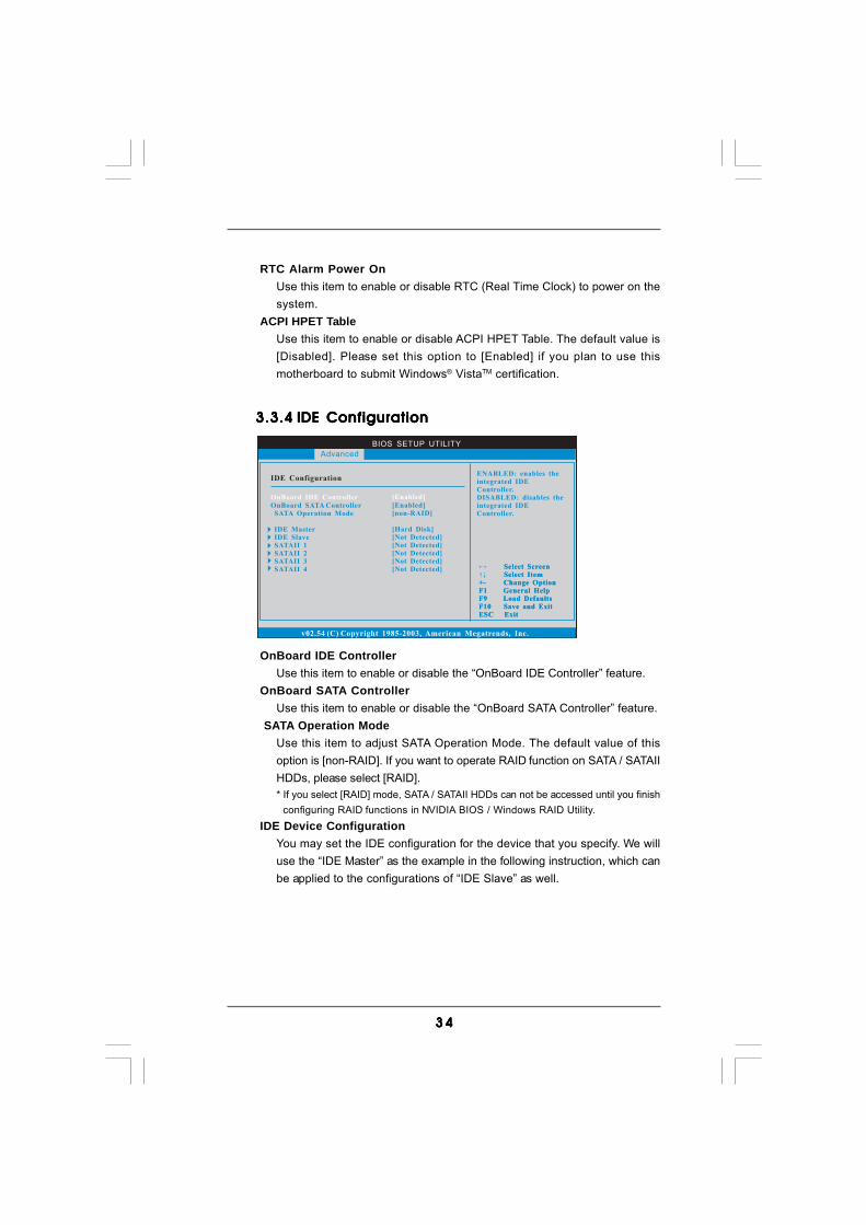
3.3.43.3.43.3.43.3.43.3.4 IDE ConfigurationIDE ConfigurationIDE ConfigurationIDE ConfigurationIDE Configuration
OnBoard IDE ControllerUse this item to enable or disable the “OnBoard IDE Controller” feature.
OnBoard SATA ControllerUse this item to enable or disable the “OnBoard SATA Controller” feature.
SATA Operation ModeUse this item to adjust SATA Operation Mode. The default value of thisoption is [non-RAID]. If you want to operate RAID function on SATA / SATAIIHDDs, please select [RAID].* If you select [RAID] mode, SATA / SATAII HDDs can not be accessed until you finish configuring RAID functions in NVIDIA BIOS / Windows RAID Utility.
IDE Device ConfigurationYou may set the IDE configuration for the device that you specify. We willuse the “IDE Master” as the example in the following instruction, which canbe applied to the configurations of “IDE Slave” as well.
RTC Alarm Power OnUse this item to enable or disable RTC (Real Time Clock) to power on thesystem.
ACPI HPET TableUse this item to enable or disable ACPI HPET Table. The default value is[Disabled]. Please set this option to [Enabled] if you plan to use thismotherboard to submit Windows® VistaTM certification.
3 53 53 53 53 5
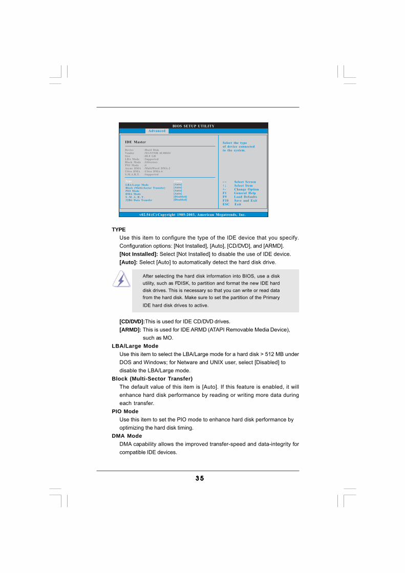
TYPEUse this item to configure the type of the IDE device that you specify.Configuration options: [Not Installed], [Auto], [CD/DVD], and [ARMD].[Not Installed]: Select [Not Installed] to disable the use of IDE device.[Auto]: Select [Auto] to automatically detect the hard disk drive.
After selecting the hard disk information into BIOS, use a diskutility, such as FDISK, to partition and format the new IDE harddisk drives. This is necessary so that you can write or read datafrom the hard disk. Make sure to set the partition of the PrimaryIDE hard disk drives to active.
[CD/DVD]:This is used for IDE CD/DVD drives.[ARMD]: This is used for IDE ARMD (ATAPI Removable Media Device),
such as MO.LBA/Large Mode
Use this item to select the LBA/Large mode for a hard disk > 512 MB underDOS and Windows; for Netware and UNIX user, select [Disabled] todisable the LBA/Large mode.
Block (Multi-Sector Transfer)The default value of this item is [Auto]. If this feature is enabled, it willenhance hard disk performance by reading or writing more data duringeach transfer.
PIO ModeUse this item to set the PIO mode to enhance hard disk performance byoptimizing the hard disk timing.
DMA ModeDMA capability allows the improved transfer-speed and data-integrity forcompatible IDE devices.
BIOS SETUP UTILITY
IDE Master Select the typeof device connectedto the system.
Select ScreenSelect Item
+- Change OptionF1 General HelpF9 Load DefaultsF10 Save and ExitESC Exit
v02.54 (C) Copyright 1985-2003, American Megatrends, Inc.
Advanced
Type
LBA/Large ModeBlock (Multi-Sector Transfer)PIO ModeDMA ModeS . M . A . R . T .32Bit Data Transfer
[Auto]
[Auto][Auto][Auto][Auto][Disabled][Disabled]
DeviceVendorSizeLBA ModeBlock ModePIO ModeAsync DMAUltra DMAS.M.A.R.T.
:Hard Disk:MAXTOR 6L080J4:80.0 GB:Supported:16Sectors:4:MultiWord DMA-2:Ultra DMA-6:Supported
3 63 63 63 63 6
BIOS SETUP UTILITY
Advanced PCI / PnP Settings Value in units of PCIclocks for PCI devicelatency timerregister.
Select ScreenSelect Item
+- Change OptionF1 General HelpF9 Load DefaultsF10 Save and ExitESC Exit
v02.54 (C) Copyright 1985-2003, American Megatrends, Inc.
PCI Latency TimerPCI IDE BusMaster
[64][Enabled]
Advanced
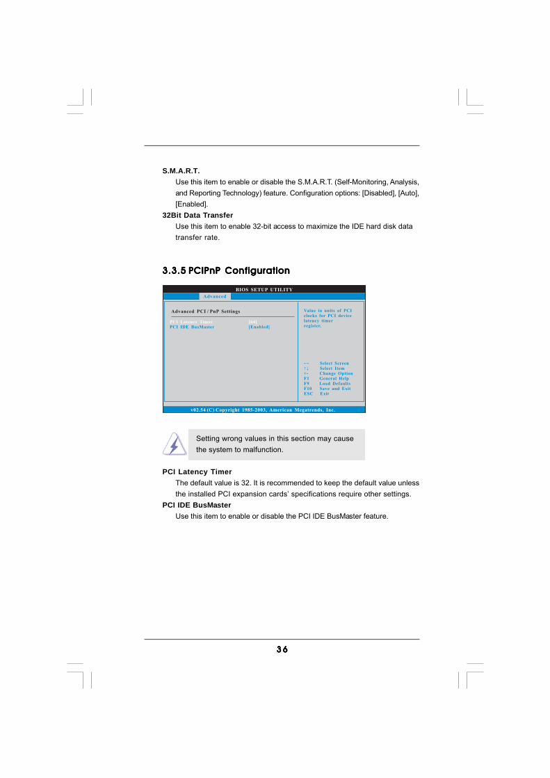
S.M.A.R.T.Use this item to enable or disable the S.M.A.R.T. (Self-Monitoring, Analysis,and Reporting Technology) feature. Configuration options: [Disabled], [Auto],[Enabled].
32Bit Data TransferUse this item to enable 32-bit access to maximize the IDE hard disk datatransfer rate.
3.3.53.3.53.3.53.3.53.3.5 PCIPnP ConfigurationPCIPnP ConfigurationPCIPnP ConfigurationPCIPnP ConfigurationPCIPnP Configuration
Setting wrong values in this section may causethe system to malfunction.
PCI Latency TimerThe default value is 32. It is recommended to keep the default value unlessthe installed PCI expansion cards’ specifications require other settings.
PCI IDE BusMasterUse this item to enable or disable the PCI IDE BusMaster feature.
3 73 73 73 73 7
BIOS SETUP UTILITY
Floppy Configuration Select the type offloppy driveconnected to thesystem.
Select ScreenSelect Item
+- Change OptionF1 General HelpF9 Load DefaultsF10 Save and ExitESC Exit
v02.54 (C) Copyright 1985-2003, American Megatrends, Inc.
Advanced
Floppy A [1.44 MB 3 "]12
BIOS SETUP UTILITY
Configure Super IO Chipset Allow BIOS to Enableor Disable FloppyController.
Select ScreenSelect Item
+- Change OptionF1 General HelpF9 Load DefaultsF10 Save and ExitESC Exit
v02.54 (C) Copyright 1985-2003, American Megatrends, Inc.
Advanced
OnBoard Floppy ControllerSerial Port AddressInfrared Port AddressParallel Port Address
Parallel Port ModeEPP VersionECP Mode DMA Channel
Parallel Port IRQOnBoard Game PortOnBoard MIDI Port
[Enabled][3F8 / IRQ4][Disabled][378][ECP + EPP][1.9][DMA3][IRQ7][Enabled][Disabled]
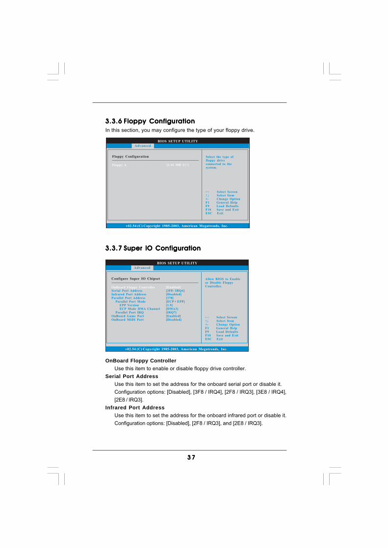
3.3.63.3.63.3.63.3.63.3.6 Floppy ConfigurationFloppy ConfigurationFloppy ConfigurationFloppy ConfigurationFloppy ConfigurationIn this section, you may configure the type of your floppy drive.
3.3.73.3.73.3.73.3.73.3.7 Super IO ConfigurationSuper IO ConfigurationSuper IO ConfigurationSuper IO ConfigurationSuper IO Configuration
OnBoard Floppy ControllerUse this item to enable or disable floppy drive controller.
Serial Port AddressUse this item to set the address for the onboard serial port or disable it.Configuration options: [Disabled], [3F8 / IRQ4], [2F8 / IRQ3], [3E8 / IRQ4],[2E8 / IRQ3].
Infrared Port AddressUse this item to set the address for the onboard infrared port or disable it.Configuration options: [Disabled], [2F8 / IRQ3], and [2E8 / IRQ3].
3 83 83 83 83 8
BIOS SETUP UTILITY
USB Configuration To enable or disablethe onboard USBcontrollers.
Select ScreenSelect Item
+- Change OptionF1 General HelpF9 Load DefaultsF10 Save and ExitESC Exit
v02.54 (C) Copyright 1985-2003, American Megatrends, Inc.
Advanced
USB Controller
USB 2.0 SupportLegacy USB Support
[Enabled]
[Enabled][Disabled]
Parallel Port AddressUse this item to set the address for the onboard parallel port or disable it.Configuration options: [Disabled], [378], and [278].Parallel Port Mode
Use this item to set the operation mode of the parallel port. The defaultvalue is [ECP+EPP]. If this option is set to [ECP+EPP], it will show the EPPversion in the following item, “EPP Version”. Configuration options:[Normal], [Bi-Directional], and [ECP+EPP].EPP Version
Use this item to set the EPP version. Configuration options: [1.9]and [1.7].
ECP Mode DMA ChannelUse this item to set the ECP mode DMA channel. Configurationoptions: [DMA0], [DMA1], and [DMA3].
Parallel Port IRQUse this item to set the IRQ for the parallel port. Configuration options:[IRQ5] and [IRQ7].
OnBoard Game PortUse this item to enable the Game Port or disable it. Configuration options:[Auto], [Enabled] and [Disabled].
OnBoard MIDI PortUse this itme to select the address for the MIDI Port or disable it. Configura-tion options: [Disabled], [300], and [330].
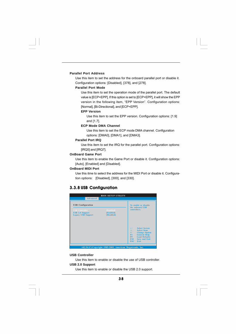
3.3.83.3.83.3.83.3.83.3.8 USB ConfigurationUSB ConfigurationUSB ConfigurationUSB ConfigurationUSB Configuration
USB ControllerUse this item to enable or disable the use of USB controller.
USB 2.0 SupportUse this item to enable or disable the USB 2.0 support.
3 93 93 93 93 9
BIOS SETUP UTILITY
Hardware Health Event Monitoring
Select ScreenSelect Item
F1 General HelpF9 Load DefaultsF10 Save and ExitESC Exit
v02.54 (C) Copyright 1985-2003, American Megatrends, Inc.
CPU TemperatureM / B Temperature
CPU Fan SpeedChassis Fan Speed
Vcore+ 3.30V+ 5.00V+ 12.00V
CPU Quiet Fan
: 37 C / 98 F
: 2833 RPM: N / A
: 1.532 V: 3.129 V: 4.877 V: 11.741 V
: 31 C / 87 F
[Disabled]
Main Advanced Boot Security ExitH/W Monitor
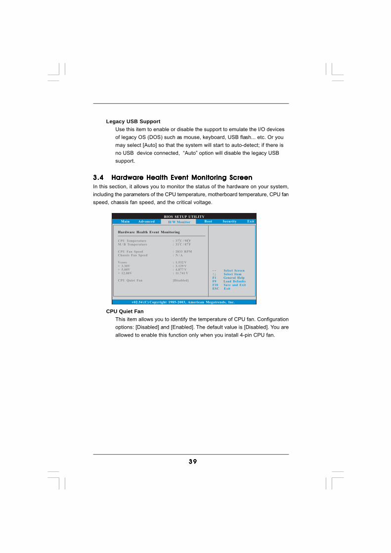
Legacy USB SupportUse this item to enable or disable the support to emulate the I/O devicesof legacy OS (DOS) such as mouse, keyboard, USB flash... etc. Or youmay select [Auto] so that the system will start to auto-detect; if there isno USB device connected, “Auto” option will disable the legacy USBsupport.
3.43.43.43.43.4 Hardware Health Event Monitoring ScreenHardware Health Event Monitoring ScreenHardware Health Event Monitoring ScreenHardware Health Event Monitoring ScreenHardware Health Event Monitoring ScreenIn this section, it allows you to monitor the status of the hardware on your system,including the parameters of the CPU temperature, motherboard temperature, CPU fanspeed, chassis fan speed, and the critical voltage.
CPU Quiet FanThis item allows you to identify the temperature of CPU fan. Configurationoptions: [Disabled] and [Enabled]. The default value is [Disabled]. You areallowed to enable this function only when you install 4-pin CPU fan.

4 04 04 04 04 0
BIOS SETUP UTILITY
Main Advanced H/W Monitor Security Exit
Boot SettingsConfigure Settingsduring System Boot.
Select ScreenSelect Item
Enter Go to Sub ScreenF1 General HelpF9 Load DefaultsF10 Save and ExitESC Exit
v02.54 (C) Copyright 1985-2003, American Megatrends, Inc.
Boot
Boot Settings Configuration
1st Boot Device2nd
Removable DrivesCD/DVD Drives
Boot Device3rd Boot DeviceHard Disk Drives
[1st Floppy Device][HDD: PM-MAXTOR 6L08][CD/DVD: SM-CD-ROM]
BIOS SETUP UTILITY
Boot Settings ConfigurationTo enable or disable theboot from onboard LANfeature.
Select ScreenSelect Item
+ - Change OptionF1 General HelpF9 Load DefaultsF10 Save and ExitESC Exit
v02.54 (C) Copyright 1985-2003, American Megatrends, Inc.
Boot
Boot From Onboard LANBootup Num-Lock
[Disabled][On]
3.53.53.53.53.5 Boot ScreenBoot ScreenBoot ScreenBoot ScreenBoot ScreenIn this section, it will display the available devices on your system for you to config-ure the boot settings and the boot priority.
3.5.13.5.13.5.13.5.13.5.1 Boot Settings ConfigurationBoot Settings ConfigurationBoot Settings ConfigurationBoot Settings ConfigurationBoot Settings Configuration
Boot From Onboard LANUse this item to enable or disable the Boot From Onboard LAN feature.
Boot Up Num-LockIf this item is set to [On], it will automatically activate the Numeric Lockfunction after boot-up.

4 14 14 14 14 1
3.63.63.63.63.6 Security ScreenSecurity ScreenSecurity ScreenSecurity ScreenSecurity ScreenIn this section, you may set or change the supervisor/user password for the system.For the user password, you may also clear it.
BIOS SETUP UTILITY
Main Advanced H/W Monitor Boot Exit
Install or Change thepassword.
Select ScreenSelect Item
Enter ChangeF1 General Help
F10 Save and ExitESC Exit
F9 Load Defaults
v02.54 (C) Copyright 1985-2003, American Megatrends, Inc.
Security
Change Supervisor Password
Change User Password
Security Settings
Supervisor Password : Not InstalledUser Password : Not Installed

4 24 24 24 24 2
BIOS SETUP UTILITY
Main Advanced H/W Monitro Boot Security
Exit system setupafter saving thechanges.
F10 key can be usedfor this operation.
Select ScreenSelect Item
Enter Go to Sub ScreenF1 General Help
F10 Save and ExitESC Exit
F9 Load Defaults
v02.54 (C) Copyright 1985-2003, American Megatrends, Inc.
Exit
Save Changes and Exit
Discard Changes and ExitDiscard Changes
Load Optimal Defaults
Exit Options
3.73.73.73.73.7 Exit ScreenExit ScreenExit ScreenExit ScreenExit Screen
Save Changes and ExitWhen you select this option, it will pop-out the following message, “Saveconfiguration changes and exit setup?” Select [OK] to save the changesand exit the BIOS SETUP UTILITY.
Discard Changes and ExitWhen you select this option, it will pop-out the following message, “Dis-card changes and exit setup?” Select [OK] to exit the BIOS SETUP UTILITYwithout saving any changes.
Discard ChangesWhen you select this option, it will pop-out the following message, “Dis-card changes?” Select [OK] to discard all changes.
Load Optimal DefaultsWhen you select this option, it will pop-out the following message, “Loadoptimal defaults?” Select [OK] to load the default values for all the setupconfigurations.
4 34 34 34 34 3
4.4.4.4.4. Software SupporSoftware SupporSoftware SupporSoftware SupporSoftware Supporttttt4.1 Install Operating System4.1 Install Operating System4.1 Install Operating System4.1 Install Operating System4.1 Install Operating SystemThis motherboard supports various Microsoft® Windows® operating systems:2000 / XP / XP 64-bit / VistaTM / VistaTM 64-bit. Because motherboard settings andhardware options vary, use the setup procedures in this chapter for general refer-ence only. Refer to your OS documentation for more information.
4.2 Support CD Information4.2 Support CD Information4.2 Support CD Information4.2 Support CD Information4.2 Support CD InformationThe Support CD that came with the motherboard contains necessary drivers anduseful utilities that enhance the motherboard features.
4.2.1 Running The Support CD4.2.1 Running The Support CD4.2.1 Running The Support CD4.2.1 Running The Support CD4.2.1 Running The Support CDTo begin using the support CD, insert the CD into your CD-ROM drive. The CDautomatically displays the Main Menu if “AUTORUN” is enabled in your computer.If the Main Menu did not appear automatically, locate and double click on the file“ASSETUP.EXE” from the BIN folder in the Support CD to display the menus.
4.2.2 Drivers Menu4.2.2 Drivers Menu4.2.2 Drivers Menu4.2.2 Drivers Menu4.2.2 Drivers MenuThe Drivers Menu shows the available devices drivers if the system detects theinstalled devices. Please install the necessary drivers to activate the devices.
4.2.3 Utilities Menu4.2.3 Utilities Menu4.2.3 Utilities Menu4.2.3 Utilities Menu4.2.3 Utilities MenuThe Utilities Menu shows the applications software that the motherboard supports.Click on a specific item then follow the installation wizard to install it.
4.2.44.2.44.2.44.2.44.2.4 Contact InformationContact InformationContact InformationContact InformationContact InformationIf you need to contact ASRock or want to know more about ASRock, welcometo visit ASRock’s website at http://www.asrock.com; or you may contact yourdealer for further information.
Recommended