Engng Applic. Artif. Intell. Vol. 4, No. 6, pp. 433-438, 1991 Printed in Great Britain. All rights reserved
Contributed Paper
0952-1976/91 $3.00 + 0.00 Copyright 0 1991 Pergamon Press plc
Knowledge-based Line-correction Rules in a Machine-vision System for the Leather Industry
ATTILA LERCH Hungarian Academy of Sciences, Budapest
DMITRY CHETVERIKOV Hungarian Academy of Sciences, Budapest
LeaVis (for Leather Vision) is a machine-vision system that provides visual input for a CAD system used in the leather industry. It has recently been developed in the Computer Vision and Robotics Laboratory of the Computer and Automation Institute. Its task is to process and segment images of hides that are manually marked by lines and other symbols. A key feature of the vision system is its ability to correct line drawings by connecting broken lines and bridging gaps in line junctions. The correction is guided by a set of knowledge-based rules that allow the program to handle the contours in a consistent way. The paper gives an overview of LeaVis and discusses the mechanism of line correction in more detail.
Keywords: Image analysis, industrial application, knowledge-based rules, line correction.
THE TASK OF THE VISION SYSTEM
In the shoe and upholstery industry, large hides are cut into pieces of desired shapes, e.g. parts of shoes. Normally, a hide has defects and areas of different quality suitable for different pieces. A limited number of expensive computer systems exist that help to auto- mate the visual input of a hide image in order to optimize the cutting process by using a computer-aided layout design system and a programmable knife.
LeaVis (for Leather Vision) is a machine-vision system for the analysis of hide images which has recently been developed at the Computer and Automation Institute in cooperation with VICAM, a leading Austrian company producing CAD software for the shoe and upholstery industry. In the current setup, a human operator manually draws on the hides the borders of the quality areas (Q-areas), marks the areas by specially designed stamps (called quality marks, or Q-marks) and indicates the defects. The vision system acquires an image of the marked hides, processes and corrects the line drawing, recognizes the stamps and segments the image. A polygonal represen- tation of the quality areas is passed to a CAD system.
Full automation of the process is a challenging but
Correspondence should be sent to: A. Lerch, Computer and Automation Institute, Hungarian Academy of Sciences Budapest, P.O. Box 63, H-1518 Hungary.
extremely difficult problem. Manual marking is needed because the image of a hide surface does not contain all the information that is necessary to determine the quality areas. Some other factors such as the local thickness of the hide must also be taken into account.
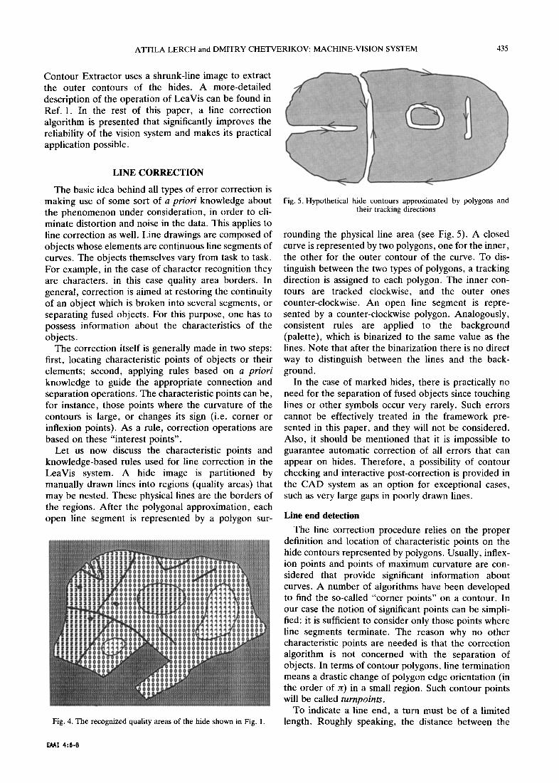
The manual indication of the quality areas simplifies the task of the vision system, but a few serious prob- lems still remain. Hide images are quite noisy. A key problem is the quality of the manual drawing which is far from being perfect. There are gaps in lines and line junctions that reach 20-30 pixels. Because of the limited capacities of the hardware used and the very high resolution required, line correction must be achieved in software. Hide images whose size is approx 7000 x7000 pixels must be coded and compressed at the very beginning of the processing. On the other hand, the execution time of the program is limited by the manufacturing process.
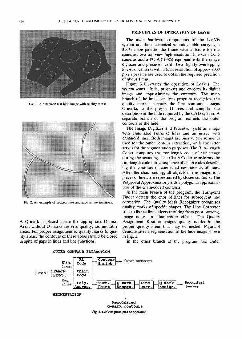
An image may contain several hides of similar col- our. Touching hides are treated as one hide. The outer contours of hides, including possible holes, have also to be found. Figure 1 shows a binarized test image of a hide. The manually drawn lines define regions of uniform quality and defect areas. The lines have gaps as illustrated by Fig. 2. A quality area border may partly be formed by the outer contour of a hide. Q-areas may be nested in arbitrary depth. Each Q-area except the defect (zero quality) areas is marked by a quality mark.
433
434 ATTILA LERCHandDMITRYCHETVERIKOV:MACHINE-VISIONSYSTEM
Fig. 1. A binarized test hide image with quality marks
Fig. 2. An example of broken lines and gaps in line junctions.
A Q-mark is placed inside the appropriate Q-area. Areas without Q-marks are zero quality, i.e. unusable areas. For proper assignment of quality marks to qua- lity areas, the contours of these areas should be closed in spite of gaps in lines and line junctions.
OUTER CONTOUR EXTRACTION
PRINCIPLES OF OPERATION OF LeaVis
The main hardware components of the LeaVis system are the mechanical scanning table carrying a 3 x 4 m size palette, the frame with a fixture for the cameras, two top-view high-resolution line-scan CCD cameras and a PC AT (386) equipped with the image digitizer and processor card. Two slightly overlapping line-scan cameras with a total resolution of approx 7000 pixels per line are used to obtain the required precision of about 1 mm.
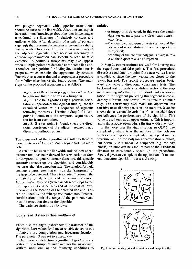
Figure 3 illustrates the operation of LeaVis. The system scans a hide, processes and encodes its digital image and approximates the contours. The main branch of the image analysis program recognizes the quality marks, corrects the line contours, assigns Q-marks to the proper Q-areas and compiles the description of the hide required by the CAD system. A separate branch of the program extracts the outer contours of the hide.
The Image Digitizer and Processor yield an image with eliminated (shrunk) lines and an image with enhanced lines. Both images are binary. The former is used for the outer contour extraction, while the latter serves for the segmentation purposes. The Run-Length Coder computes the run-length code of the image during the scanning. The Chain Coder transforms the run-length code into a sequence of chain codes describ- ing the contours of connected components of lines. After the chain coding, all objects in the image, e.g. pieces of lines, are represented by closed contours. The Polygonal Approximator yields a polygonal approxima- tion of the chain-coded contours.
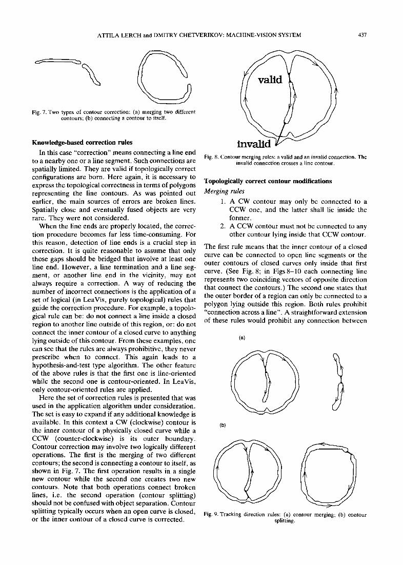
In the main branch of the program, the Turnpoint Finder detects the ends of lines for subsequent line correction. The Quality Mark Recognizer recognizes quality marks of specific shapes. The Line Corrector tries to fix the line defects resulting from poor drawing, image noise, or illumination effects. The Quality Assignment Routine assigns quality marks to the proper quality areas that may be nested. Figure 4 demonstrates a segmentation of the hide image shown in Fig. 1.
In the other branch of the program, the Outer
EIlh. lines Poly. Turn. Q-mark Line Q-mark Recognized
Awrox. Point Recoqn. Corr. Assicrn. Q-areas I
SEGMENTATION
I Recognized
Q-mark contours
Fig. 3. LeaVis: principles of operation.
ATTILA LERCH and DMITRY CHETVERIKOV: MACHINE-VISION SYSTEM
Contour Extractor uses a shrunk-line image to extract the outer contours of the hides. A more-detailed description of the operation of LeaVis can be found in Ref. 1. In the rest of this paper, a line correction algorithm is presented that significantly improves the reliability of the vision system and makes its practical application possible.
LINE CORRECTION
The basic idea behind all types of error correction is making use of some sort of a priori knowledge about the phenomenon under consideration, in order to eli- minate distortion and noise in the data. This applies to line correction as well. Line drawings are composed of objects whose elements are continuous line segments of curves. The objects themselves vary from task to task. For example, in the case of character recognition they are characters, in this case quality area borders. In general, correction is aimed at restoring the continuity of an object which is broken into several segments, or separating fused objects. For this purpose, one has to possess information about the characteristics of the objects.
The correction itself is generally made in two steps: first, locating characteristic points of objects or their elements; second, applying rules based on a priori knowledge to guide the appropriate connection and separation operations. The characteristic points can be, for instance, those points where the curvature of the contours is large, or changes its sign (i.e. corner or inflexion points). As a rule, correction operations are based on these “interest points”.
Let us now discuss the characteristic points and knowledge-based rules used for line correction in the LeaVis system. A hide image is partitioned by manually drawn lines into regions (quality areas) that may be nested. These physical lines are the borders of the regions. After the polygonal approximation, each open line segment is represented by a polygon sur-
Fig. 4. The recognized quality areas of the hide shown in Fig. 1.
EM1 4:6-6
Fig. 5. Hypothetical hide contours approximated by polygons and their tracking directions
rounding the physical line area (see Fig. 5). A closed curve is represented by two polygons, one for the inner, the other for the outer contour of the curve. To dis- tinguish between the two types of polygons, a tracking direction is assigned to each polygon. The inner con- tours are tracked clockwise, and the outer ones counter-clockwise. An open line segment is repre- sented by a counter-clockwise polygon. Analogously, consistent rules are applied to the background (palette), which is binarized to the same value as the lines. Note that after the binarization there is no direct way to distinguish between the lines and the back- ground.
In the case of marked hides, there is practically no need for the separation of fused objects since touching lines or other symbols occur very rarely. Such errors cannot be effectively treated in the framework pre- sented in this paper, and they will not be considered. Also, it should be mentioned that it is impossible to guarantee automatic correction of all errors that can appear on hides. Therefore, a possibility of contour checking and interactive post-correction is provided in the CAD system as an option for exceptional cases, such as very large gaps in poorly drawn lines.
Line end detection
The line correction procedure relies on the proper definition and location of characteristic points on the hide contours represented by polygons. Usually, inflex- ion points and points of maximum curvature are con- sidered that provide significant information about curves. A number of algorithms have been developed to find the so-called “corner points” on a contour. In our case the notion of significant points can be simpli- fied: it is sufficient to consider only those points where line segments terminate. The reason why no other characteristic points are needed is that the correction algorithm is not concerned with the separation of objects. In terms of contour polygons, line termination means a drastic change of polygon edge orientation (in the order of JC) in a small region. Such contour points will be called turnpoints.
To indicate a line end, a turn must be of a limited length. Roughly speaking, the distance between the
436 ATTILA LERCH and DMITRY CHETVERIKOV: MACHINE-VISION SYSTEM
two polygon segments with opposite orientations should be close to the line width. Also, one can exploit here additional knowledge about the lines in the images considered: the lines are of relatively constant and uniform width. After detection of a pair of polygon segments that presumably contains a line end, a validity test is needed to check the directional consistency of the adjacent segments, since noise or inaccuracy in contour approximation can sometimes lead to false detection. Superfluous turnpoints may also appear when multiple points are detected at the same line end. Therefore, an algorithm for finding line terminations is proposed which exploits the approximately constant line width as a constraint and incorporates a procedure for validity checking of the found points. The main steps of the proposed algorithm are as follows:
Step I. Scan the contour polygon; for each vertex, hypothesize that the vertex is a turnpoint. Step 2. Test the hypothesis by a pairwise orien- tation comparison of the segment running into the examined vertex, with a sequence of segments following the vertex. Terminate Step 2 if a turn- point is found, or if the compared segments are too far from each other. Step 3. If a turnpoint is found, check the direc- tional consistency of the adjacent segments and discard superfluous points.
The framework of the algorithm is similar to those of corner detectors.’ Let us discuss Steps 2 and 3 in more detail.
A relation between the line width and the look-ahead distance limit has been derived for termination of Step 2. Compared to general corner detectors, this specific constraint speeds up the algorithm and considerably decreases the false detection rate. The relation formula contains a parameter that controls the “sharpness” of the turn to be detected. There is a tradeoff between the probability of detection and its spatial precision. More-reliable detection (which needs more steps to test the hypothesis) can be achieved at the cost of lower precision in the location of the detected line end. This can be tuned by the “sharpness” parameter. Practical considerations limit the range of the parameter and thus the execution time of the algorithm.
The basic constraint is as follows:
look_ahead_%stance< line_widthlsir@,
where p is the angle (“sharpness”) parameter of the algorithm. Low values for /3 mean reliable detection but probably more computation and inaccurate location. The parameter 6 was set to approx n/4.
The line-end detection algorithm hypothesizes a vertex to be a turnpoint and examines the subsequent vertices until one of the following conditions is
satisfied:
-a turnpoint is detected; in date vertex must pass the ency test;
this case the candi- directional consist-
-the examined subsequent vertex is beyond the above look-ahead distance; then the hypothesis is rejected;
-scanning of the contour polygon is over; in this case the hypothesis is also rejected.
In Step 3, two procedures are used for filtering out the superfluous and false points. The first procedure discards a candidate turnpoint if the next vertex is also a candidate, since the next vertex lies closer to the actual line end. The second procedure applies back- ward and onward directional consistency tests. The backward test discards a candidate vertex if the seg- ment running into the vertex is short and the orien- tation of the segment preceding this segment is consi- derably different. The onward test is done in a similar way. The consistency tests make the algorithm less sensitive to small noisy peaks on line contours. It can be shown that a reasonable variation of the line width does not influence the performance of the algorithm. This value is used only as an upper estimate. This is import- ant in those applications where the line width may vary.
In the worst case the algorithm has an O(N2) time complexity, where N is the number of the polygon vertices. The expected complexity may depend on line structure and on the polygon approximation method, but normally it is linear. A simplified (e.g. the city block’) distance can be used instead of the Euclidean distance to considerably speed up the procedure. Figure 6 gives an example of the application of the line- end detection algorithm to a test drawing.
(a 1
(b)
Fig. 6. A line drawing (a) and its contours and turnpoints (b).
ATTILA LERCH and DMITRY CHETVERIKOV: MACHINE-VISION SYSTEM 437
Fig. 7. Two types of contour correction: (a) merging two different contours; (b) connecting a contour to itself.
Knowledge-based correction rules
In this case “correction” means connecting a line end to a nearby one or a line segment. Such connections are spatially limited. They are valid if topologically correct configurations are born. Here again, it is necessary to express the topological correctness in terms of polygons representing the line contours. As was pointed out earlier, the main sources of errors are broken lines. Spatially close and eventually fused objects are very rare. They were not considered.
When the line ends are properly located, the correc- tion procedure becomes far less time-consuming. For this reason, detection of line ends is a crucial step in correction. It is quite reasonable to assume that only those gaps should be bridged that involve at least one line end. However, a line termination and a line seg- ment, or another line end in the vicinity, may not always require a correction. A way of reducing the number of incorrect connections is the application of a set of logical (in LeaVis, purely topological) rules that guide the correction procedure. For example, a topolo- gical rule can be: do not connect a line inside a closed region to another line outside of this region, or: do not connect the inner contour of a closed curve to anything lying outside of this contour. From these examples, one can see that the rules are always prohibitive, they never prescribe when to connect. This again leads to a hypothesis-and-test type algorithm. The other feature of the above rules is that the first one is line-oriented while the second one is contour-oriented. In LeaVis, only contour-oriented rules are applied.
Here the set of correction rules is presented that was used in the application algorithm under consideration. The set is easy to expand if any additional knowledge is available. In this context a CW (clockwise) contour is the inner contour of a physically closed curve while a CCW (counter-clockwise) is its outer boundary. Contour correction may involve two logically different operations. The first is the merging of two different contours; the second is connecting a contour to itself, as shown in Fig. 7. The first operation results in a single new contour while the second one creates two new contours. Note that both operations connect broken lines, i.e. the second operation (contour splitting) should not be confused with object separation. Contour splitting typically occurs when an open curve is closed, or the inner contour of a closed curve is corrected.
Fig. 8. Contour merging rules: a valid and an invalid connection. The invalid connection crosses a line contour.
Topologically correct contour modifications
Merging rules
1. A CW contour may only be connected to a CCW one, and the latter shall lie inside the former.
2. A CCW contour must not be connected to any other contour lying inside that CCW contour.
The first rule means that the inner contour of a closed curve can be connected to open line segments or the outer contours of closed curves only inside that first curve. (See Fig. 8; in Figs 8-10 each connecting line represents two coinciding vectors of opposite direction that connect the contours.) The second one states that the outer border of a region can only be connected to a polygon lying outside this region. Both rules prohibit “connection across a line”. A straightforward extension of these rules would prohibit any connection between
(4
(b)
Fig. 9. Tracking direction rules: (a) contour merging; (b) contour splitting.
438 ATTILA LERCH and DMITRY CHETVERIKOV: MACHINE-VISION SYSTEM
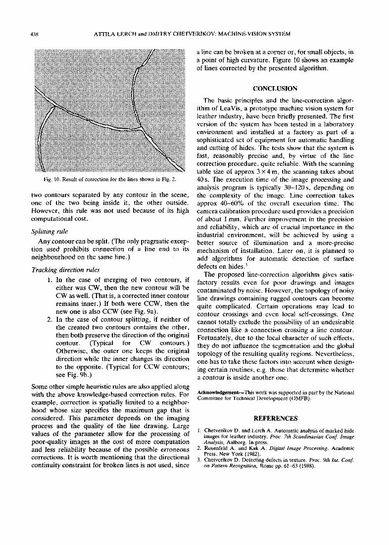
Fig. 10. Result of correction for the lines shown in Fig. 2.
two contours separated by any contour in the scene, one of the two being inside it, the other outside. However, this rule was not used because of its high computational cost.
Splitting rule
Any contour can be split. (The only pragmatic excep- tion used prohibits connection of a line end to its neighbourhood on the same line.)
Tracking direction rules
1. In the case of merging of two contours, if either was CW, then the new contour will be CW as well. (That is, a corrected inner contour remains inner.) If both were CCW, then the new one is also CCW (see Fig. 9a).
2. In the case of contour splitting, if neither of the created two contours contains the other, then both preserve the direction of the original contour. (Typical for CW contours.) Otherwise, the outer one keeps the original direction while the inner changes its direction to the opposite. (Typical for CCW contours; see Fig. 9b.)
Some other simple heuristic rules are also applied along with the above knowledge-based correction rules. For example, correction is spatially limited to a neighbor- hood whose size specifies the maximum gap that is considered. This parameter depends on the imaging process and the quality of the line drawing. Large values of the parameter allow for the processing of poor-quality images at the cost of more computation and less reliability because of the possible erroneous corrections. It is worth mentioning that the directional continuity constraint for broken lines is not used, since
a line can be broken at a corner or, for small objects, in a point of high curvature. Figure 10 shows an example of lines corrected by the presented algorithm.
CONCLUSION
The basic principles and the line-correction algor- ithm of LeaVis, a prototype machine vision system for leather industry, have been briefly presented. The first version of the system has been tested in a laboratory environment and installed at a factory as part of a sophisticated set of equipment for automatic handling and cutting of hides. The tests show that the system is fast, reasonably precise and, by virtue of the line correction procedure, quite reliable. With the scanning table size of approx 3 x 4 m, the scanning takes about 40 s. The execution time of the image processing and analysis program is typically 30-120 s, depending on the complexity of the image. Line correction takes approx 40-60% of the overall execution time. The camera calibration procedure used provides a precision of about 1 mm. Further improvement in the precision and reliability, which are of crucial importance in the industrial environment, will be achieved by using a better source of illumination and a more-precise mechanism of installation. Later on, it is planned to add algorithms for automatic detection of surface defects on hides.3
The proposed line-correction algorithm gives satis- factory results even for poor drawings and images contaminated by noise. However, the topology of noisy line drawings containing rugged contours can become quite complicated. Certain operations may lead to contour crossings and even local self-crossings. One cannot totally exclude the possibility of an undesirable connection like a connection crossing a line contour. Fortunately, due to the local character of such effects, they do not influence the segmentation and the global topology of the resulting quality regions. Nevertheless, one has to take these factors into account when design- ing certain routines, e.g. those that determine whether a contour is inside another one.
Acknowledgement-This work was supported in part by the National Committee for Technical Development (OMFB).
REFERENCES
1. Chetverikov D. and Lerch A. Automatic analysis of marked hide images for leather industry. Proc. 7th Scandinavian Conf Image Analysis, Aalborg. In press.
2. Rosenfeld A. and Kak A. Digital Image Processing. Academic Press, New York (1982).
3. Chetverikov D. Detecting defects in texture. Proc. 9th Int. Conf on Pattern Recognition, Rome pp. 61-63 (1988).
Recommended