Laser Acceleration of Quasi-Monoenergetic MeV-GeV Ion BeamsBeams
presented by:LAUR-07-xxxx
Juan C. Fernández, Group LeaderGroup P-24 Plasma Physics, Los Alamos National Laboratory
presented to:presented to:LINAC08 ConferenceVictoria, British Columbia, CanadaSept. 29 – Oct. 3, 2008
My Documents\Presentations\Conferences_and_workshops\LINAC081

The latest C ion acceleration project joins a multi
Participants Organization Contribution/ExpertiseJ C F á d LANL P 24 P i i l I ti t i t
The latest C-ion acceleration project joins a multi-disciplinary team of LANL and LMU researchers.
Juan C. Fernández LANL P-24 Principal Investigator, experimentsBjörn Manuel Hegelich LANL P-24 Co PI, experiments on short-pulse lasersKirk A. Flippo LANL P-24 P-24 Experiments on short-pulse lasersRahul Shah LANL P-24 P-24 Exps. on short-pulse lasers, laser scienceRandall P. Johnson LANL P-24 Laser science, TridentRandall P. Johnson LANL P 24 Laser science, TridentTsutomu Shimada LANL P-24 P-24 Laser science, TridentSam Letzring LANL P-24 P-24 Experimental OperationsCort Gautier LANL P-24 P-24 Trident experiments, surface physicsBrian J. Albright LANL P-24 X-1 Relativistic laser-matter theory and Sim.Li Yi LANL P 24 X 1 R l ti i ti l tt th d SiLin Yin LANL P-24 X-1 Relativistic laser-matter theory and Sim.Mark J. Schmitt LANL P-24 X-1 Laser-plasma design with Rad-Hydro codesRoland K. Schulze LANL P-24 MST6 Surface physics & material scienceRichard Sheffield LANL LANSCE Accelerator physicsAndreas Henig LMU Experiments on short-pulse lasersg p pDaniel Kiefer LMU Experiments on short-pulse lasersDaniel Jung LMU Experiments on short-pulse lasers, targets
• Significant collaborations with other institutions, including students, Post Docs, professors and research staff from:research staff from:
– LLNL; SNL, LULI (Ecole Polytechnique, Palaiseau, Paris, France); GSI (Darmstadt, Germany); Technical University of Darmstadt (TUD); Ludwig Maximilians University (LMU, Munich, Germany); Univ. of Nevada, Reno (UNR); Nanolabz, Reno, NV; Queens Univ. Belfast (QUB), UK.
My Documents\Presentations\Conferences_and_workshops\LINAC082

O tliOutline:
• Why laser-driven accelerators? Pinhole camera RCF for protonstarget
• Background & history
target
• Mechanisms for laser-driven ion acceleration
Static grid
– Target Normal Sheath Acceleration (TNSA)
– Breakout Afterburner (BOA)– Radiation Pressure Acceleration (RPA)Radiation Pressure Acceleration (RPA)
• Future
• Summary
My Documents\Presentations\Conferences_and_workshops\LINAC083

Why laser-driven ion beams?Background
• Characteristics– Smaller size (limited by laser)– Generated in ~ ps bunches
Why laser-driven ion beams?
– Generated in ~ ps bunches– Born with high-current (~ A – MA)
o Neutralized beam• Ideal applicationsIdeal applications
– Transient phenomena (1 shot)– Require high energy density– Sensitive to capital costp→ Beam made O(cm) from target
• Examples– Human cancer therapy Fusion Fast Ignitionpy– Isochoric heating of matter– Fast ignition ICF– Nuclear interrogation
Fusion Fast Ignition
• Challenges– Energy spectrum control– Laser Techn. (pulse shape, rep rate)
My Documents\Presentations\Conferences_and_workshops\LINAC08
– Target technology
4
S f l d i i l ti
Background
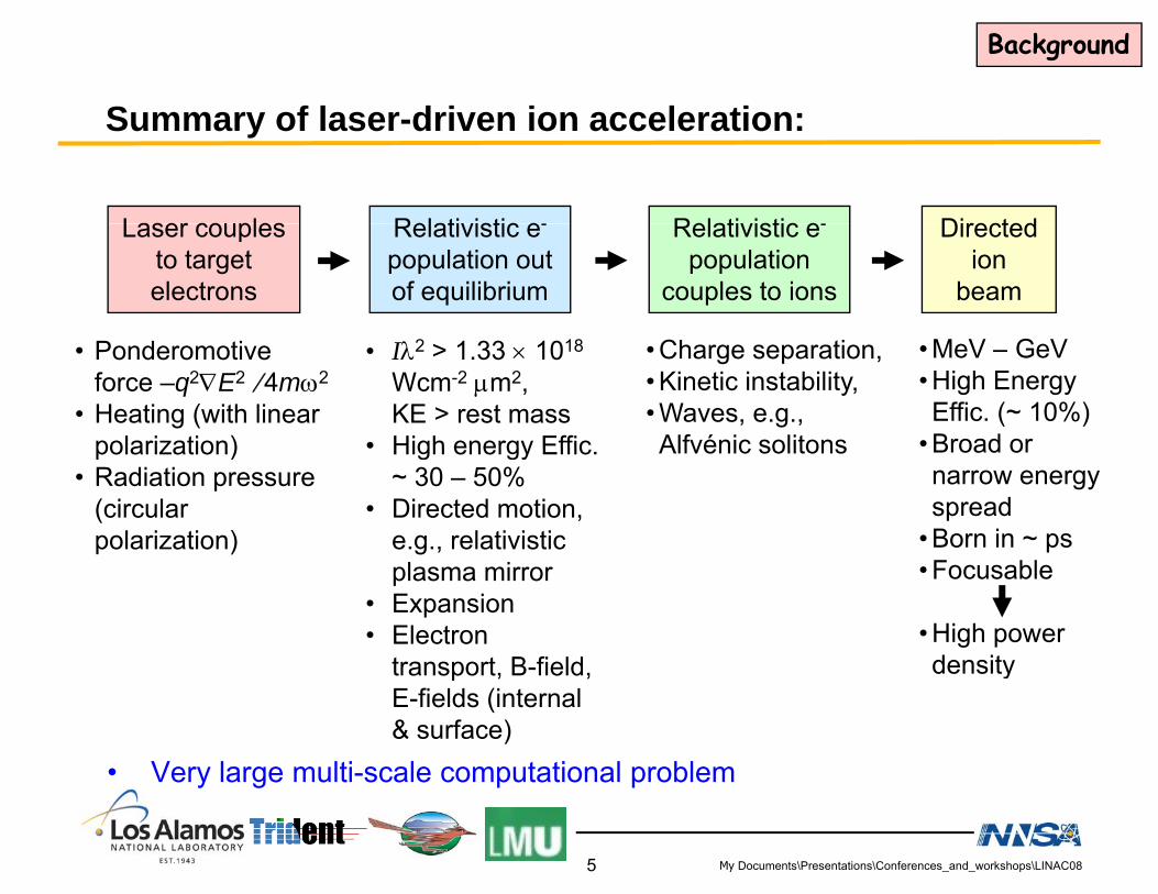
Summary of laser-driven ion acceleration:
Laser couples Relativistic e- Relativistic e- DirectedLaser couples to target electrons
Relativistic e-
population out of equilibrium
Relativistic e-
population couples to ions
Directed ion
beam
• Ponderomotive force –q2∇E2 ⁄ 4mω2
• Heating (with linear polarization)
• Iλ2 > 1.33 × 10¹⁸
Wcm-2 μm2, KE > rest mass
• High energy Effic
• Charge separation, • Kinetic instability, • Waves, e.g., Alfvénic solitons
• MeV – GeV• High Energy Effic. (~ 10%)
• Broad orpolarization)• Radiation pressure
(circular polarization)
• High energy Effic. ~ 30 – 50%
• Directed motion, e.g., relativistic
Alfvénic solitons Broad or narrow energy spread
• Born in ~ psplasma mirror
• Expansion• Electron
transport B-field
• Focusable
• High power density
• Very large multi-scale computational problem
transport, B field, E-fields (internal & surface)
density
My Documents\Presentations\Conferences_and_workshops\LINAC08
y g p p
5

Ion acceleration mechanisms:
Background
Ion acceleration mechanisms:Ion acceleration mechanism
Acronym Ion Accel. process foil
10μmTNSA
Target-Normal Sheath Acceleration
TNSA Charge separation
laser10μm
Break out afterburner BOA Kinetic
protons
BOA
Instability (Buneman): relative e-i drift
laser
Radiation Pressure Acceleration
RPA Charge separation RPA
Aka Plasma Piston laser
My Documents\Presentations\Conferences_and_workshops\LINAC086

Quick historical overview of > MeV ion accelerationBackground
Year Key milestone Reference1992 Ponderomotive scaling of laser-driven hot
electrons explained in PIC simulationsS. C. Wilks, et al., Phys. Rev. Lett. 69, 1383 (1992)
1999 ~ 1013 protons, Maxwellian, ~ 60 MeV cutoff, @ NOVA PW laser - LLNL
R. Snavely et al., PRL 85, 2945 (2000)
2000 TNSA mechanism explained S. Hatchett et al., Phys. Plas. 7, 2076 (2000)
2001-2002
Record low transverse emittance for proton beam, @ Trident (LANL) & LULI
T. E. Cowan et al., Phys. Rev. Lett. 92, 204801 (2004)
2001-2002
TNSA confirmed: protons come from target back side @ Trident (LANL) & LULI
J. Fuchs et al., Phys. Rev. Lett. 94, 045004 (2005)2002 back side, @ Trident (LANL) & LULI (2005)
2002 TNSA heavy ion beams, @ LULI B. M. Hegelich et al., PRL 89, 085002 (2002)
2003 Proton beam focused ballistically, @ LLNL P. K. Patel et al., Phys. Rev. Lett. 92, 125004 Janusp laser (2003)
2005 Quasi-monoenergetic C beam, @ Trident B. M. Hegelich et al., Nature 439, 441 (2006)
2005 BOA (~ GeV, quasi-monoenergetic) di d i PIC i l ti @ LANL
L. Yin et al., Laser Part. Beams 24, 291 (2006) Ph Pl 14 056706 (2007)discovered in PIC simulations, @ LANL (2006) ; Phys. Plasmas 14, 056706 (2007)
2007 RPA accessible at 1021 W/cm2 with circular polarization
A.P.L. Robinson, et al., New J. Phys. 10, 013021 (2008)
2008 1st BOA & RPA experiments @ Trident
My Documents\Presentations\Conferences_and_workshops\LINAC08
2008 1st BOA & RPA experiments @ Trident
7

Brief Overview of Laser-Ion AccelerationT N l Sh h A l i (TNSA)
TNSA
Target Normal Sheath Acceleration (TNSA)
1 2Preplasma Formation Hot e- Generation…Cold return current e-
P l
e-Pre-plasma
e-
e-
Cold return current e
E E
Pre-plasma
t trefluxing e-
e-
e-
p+ p+ p+CH &H2O
CH &H2O
rear side p+
target
front side p+
gtarget
3… and hot e- Recirculation
Ion Acceleration
p2O2
E
rear side pfront side p
E
p+e-
p+p+
My Documents\Presentations\Conferences_and_workshops\LINAC08
target
8

Laser-driven TNSA proton beams have extremely low TNSA
• Hot e- → MV/μm electrostatic fields at the target rear surface (virtual cathode).
transverse emittance.
• Measured transverse emittance of TNSA proton beams at Trident (LANL) and LULI (Ecole Politechnique).
emittance
di
1 mil Al
RCFstack
18 μm
Al target
3 μm
65 mm
RCF image of Trident proton beam
laserdivergence
0.1 μm proton beam
Trident experimental setup
• For 8 MeV component of the Trident beam, the upper bound on the transverse normalized beam emittance is 0.004 mm mrad, ~ 100× better than typical LINACs.
My Documents\Presentations\Conferences_and_workshops\LINAC089

L d d i b h b f d
TNSA
Laser-produced ion beams have been focused.
• Neutralized beam: not bound by usual current and space-charge limitscharge limits
• May be focused with quadrupole lenses and ballisticallyBallistic (shaped target)Quadrupole lens focusing
P. K. Patel et al., Phys. Rev. Lett. 92, 125004 (2003)M. H. Key et al., Fusion Science & Technology 49 (2006) 440
M. Schollmeier, et al., Phys. Rev. Lett. 101, 055004 (2008)
My Documents\Presentations\Conferences_and_workshops\LINAC08
y gy ( )M. H. Key, Phys. Plasmas 14 (2007) 055502
10

Joule heating of Pd foils (evaporate surface impurities) yields
TNSA
Joule heating of Pd foils (evaporate surface impurities) yields on beam with a significant yield of highly ionized heavy ions.
• Trident 30 TW data• Trident 30 TW data
• Pd22+ ions (assuming 10º beam): 108
Target: Pd 20mm
]
Target: Pd foil, 20 μm thick
1.75 X 10⁹ ≥ 1 MeV/u → 0.23% of laser energy; 2.4 X 10¹⁰ total → 1.1% f l
107
V-1 m
srd-1
of laser energy
• Pd4+ ions (not shown): 1.1% of laser energy105
106
144: C4+ coldount
s [M
eV
C4+ , cold Pd target, CR39 ID 144Th = 0.4 MeV/u
• High-energy cutoff consistent with theory 104
10 144: C , cold 147: Pd22+, J-heated
Ionc
o
Pd22+, J-heated Pd target, CR39ID 147, Shot 16159, 17 J in 0.8 ps
0.0 0.2 0.4 0.6 0.8 1.0 1.2 1.4 1.6 1.8 2.0Energy / nucleon [MeV/u]
My Documents\Presentations\Conferences_and_workshops\LINAC0811

CW laser heating of Ni foils has resulted in ~ 1% laser
TNSA
CW laser heating of Ni foils has resulted in ~ 1% laser conversion efficiency into a Ni18+ ion beam.
T t Ni 15 thi k• Target: Ni, 15 μm thick.
• Ni18+ → 0.8 % of laser energy on old 30 TW
8
109
srd
-1] 17629 Ni18+
Predicted high-energy cutoff (assuming typical
Trident.
• High-energy cutoff (reduced model by
Predicted high-energy cutoff (assuming DL beam size)
106
107
108
s [M
eV-1
ms
17 μm laser spot)
(reduced model by Albright et al.*, E I,max ~ 2Th ZI) is higher than than expected.
Th = 0.45 MeV/u
104
105
10
Ions
Th = 0.18 MeV/u
• Self focusing probably increased intensity.0 50 100 150 200
103
Energy [MeV]
* B. A. Albright, et al., Phys. Rev. Lett. 97, 115002 (2006)
My Documents\Presentations\Conferences_and_workshops\LINAC0812
We inadvertently exploited a surface catalytic reaction to
TNSA
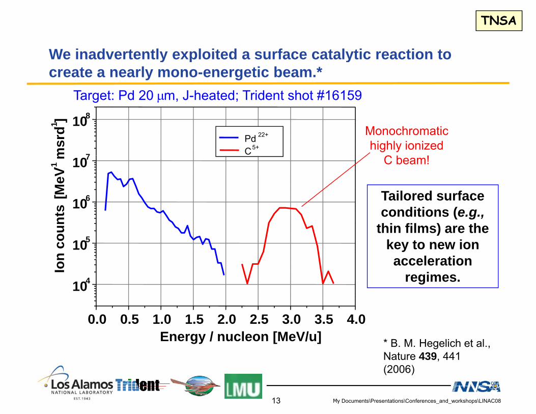
We inadvertently exploited a surface catalytic reaction to create a nearly mono-energetic beam.*
Target: Pd 20 μm, J-heated; Trident shot #16159
7
108
Pd 22+
C5+
msr
d-1]
Monochromatichighly ionized
C
106
107
s [M
eV-1
m C beam!
Tailored surface diti (
105
10
n co
unts conditions (e.g.,
thin films) are the key to new ion acceleration
104
Ion acceleration
regimes.
0.0 0.5 1.0 1.5 2.0 2.5 3.0 3.5 4.0Energy / nucleon [MeV/u] * B. M. Hegelich et al.,
Nature 439, 441
My Documents\Presentations\Conferences_and_workshops\LINAC08
(2006)
13
Heating certain metals (e g Pd) to 800 1000º C catalyzes
TNSA
• The chamber atmosphere (~ 10-6 torr) provides a
Heating certain metals (e.g. Pd) to 800 - 1000 C catalyzes a reaction leaving a few C monolayers on the surface.
• The chamber atmosphere (~ 10 6 torr) provides a source of hydrocarbons.
• Heating the target to 400 - 600º C liberates all the HHeating the target to 400 600 C liberates all the H.
• Heating the target to 600 - 800º C leaves a carbon layer. y
• Heating the target to 800 - 1000º C results in a C monolayery
• Heating the target above 1000º C liberates all surface contaminants.
My Documents\Presentations\Conferences_and_workshops\LINAC0814

Our understanding of TNSA has allowed the development of
TNSA
g preduced models for ion-acceleration dynamics.*
1D hybrid code BILBO (Backside Ion Lagrangian
108
BILBO Observed (Backside Ion Lagrangian Blow Off):
• Analytic solution to Vlasov-Maxwell system6
107
msr
d-1
] BILBOPd22+
Observed C5+
BILBOC5+
Maxwell system
• Threshold ionization model
• Hot electron cooling model 105
106
N [
MeV
-1
Ob dg
(3D effect)
8
109
N1A C5+N4A C5+
0104
1 2 3 4 5
ObservedPd22+
107
108 N10A C5+ N80A C4+, C5+ N1000A C4+, C5+
[MeV
-1 m
srd-1
]
Energy [MeV/u]
• B. J. Albright et al., Phys. Rev. Lett. 97, 115002(2006);B. M. Hegelich et al., Nature 439, 441 (2006)
0 1 2 3 4105
106N [
My Documents\Presentations\Conferences_and_workshops\LINAC08
0 1 2 3 4Energy [MeV/u]
15

Discovery of the laser-breakout afterburner* (BOA):BOA
Discovery of the laser breakout afterburner (BOA): a path to high efficiency & high energy ion beams• Requirements:
– I ~ 1020 W/cm2 with ultra-high laser contrastI 10 W/cm with ultra high laser contrast– Ultra-thin targets (e.g., ~ 30 nm C)
• 1D, 2D, 3D Simulations using VPIC code– Start with solid density C, including
cases with H contaminants• Mechanism:
– Enhanced TNSALaser penetration across target– Laser penetration across target
– Electron heating & drift relative to ions– Electron energy → ion energy via kinetic Buneman instability.
• Initial simulations (I ~ 1021 W/cm2 30 nm targets):Initial simulations (I 10 W/cm , 30 nm targets):– 35% (in 1D, 15% (in 2D) of all ions accelerated to 0.3 GeV ± 7%, 4% conversion
efficiency.– C-ion acceleration is immune to surface or volumetric proton contamination!
The key to realizing this concept is having a high (~ 1010) laser-pulse contrast to prevent the pre-pulse shock from destroying the target.
My Documents\Presentations\Conferences_and_workshops\LINAC08
* L. Yin et al., Phys. Plasmas 14, 056706 (2007)
16
Radiation Pressure Acceleration (RPA) is another path toRPA
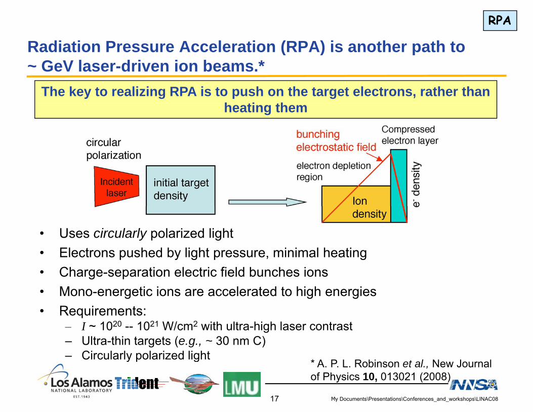
Radiation Pressure Acceleration (RPA) is another path to ~ GeV laser-driven ion beams.*
The key to realizing RPA is to push on the target electrons, rather than h ti thheating them
• Uses circularly polarized light• Electrons pushed by light pressure, minimal heatingp y g p , g• Charge-separation electric field bunches ions• Mono-energetic ions are accelerated to high energies• Requirements:
* A P L R bi t l N J l
• Requirements:– I ~ 1020 -- 1021 W/cm2 with ultra-high laser contrast– Ultra-thin targets (e.g., ~ 30 nm C)– Circularly polarized light
My Documents\Presentations\Conferences_and_workshops\LINAC08
* A. P. L. Robinson et al., New Journal of Physics 10, 013021 (2008)
y p g
17

VPIC has been used to study RPA acceleration of C, showingRPA
VPIC has been used to study RPA acceleration of C, showing acceleration to ~ GeV.• Requirements:
– I ~ 1021 W/cm2 with ultra-high laser contrastI 10 W/cm with ultra high laser contrast– Ultra-thin targets (e.g., ~ 30 nm C)– Circular polarization
• 1D simulations using solid density C 208 fs 416 fsand 208 fs pulse (blue curve)– 60% of ions accelerated to
450 MeV ± 10%, 13% conversion eff.1D li ith l l th
104 fs 208 fs 416 fs
– 1D scaling with pulse length– C-beam energy increases with
pulse length• Concern: effects of higher dimensions• Concern: effects of higher-dimensions• 3D VPIC simulations show:
– high sensitivity to curvature, which may negate benefits of circular polarization– ~ GeV energies GeV energies
• Further optimization of RPA and BOA is needed.
RPA deserves further consideration for ~ GeV ion acceleration.
My Documents\Presentations\Conferences_and_workshops\LINAC0818
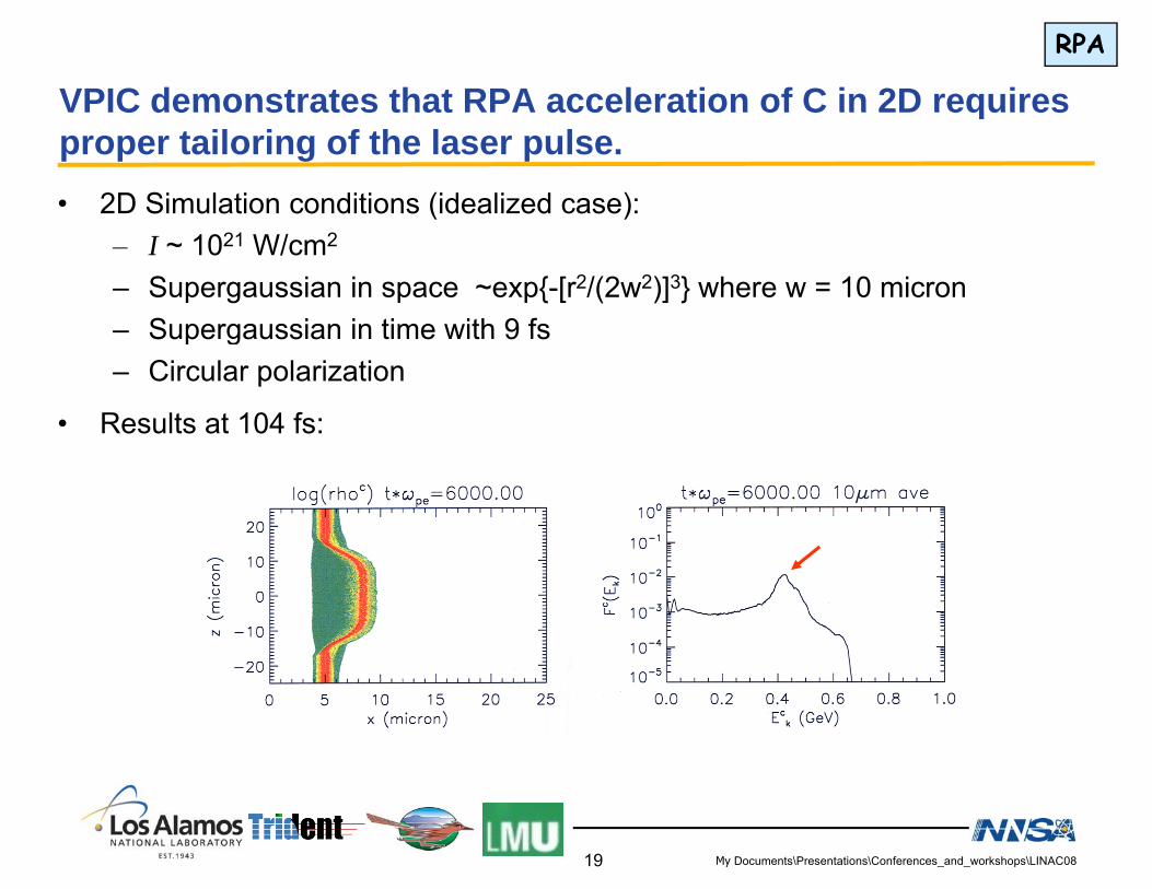
VPIC demonstrates that RPA acceleration of C in 2D requiresRPA
VPIC demonstrates that RPA acceleration of C in 2D requires proper tailoring of the laser pulse.• 2D Simulation conditions (idealized case):
– I ~ 1021 W/cm2
– Supergaussian in space ~exp{-[r2/(2w2)]3} where w = 10 micron– Supergaussian in time with 9 fsSupergaussian in time with 9 fs– Circular polarization
• Results at 104 fs:
My Documents\Presentations\Conferences_and_workshops\LINAC0819

There are two key technological requirements to access
Technology
• Ultra-thin targets (10-100 nm)
There are two key technological requirements to access ion acceleration mechanisms at the GeV level:
g ( )– Have settled on diamond-like C (DLC) as a technologically
convenient species– As part of our collaboration with Ludwig Maximilians University
(Munich), they have provided DLC targets in thicknesses of 3, 5, 10, 30, 50 & 60 nm.
• Laser pulses with ultrahigh contrast (~ 1010) and no prepulse– Have discovered that post-pulses can turn into prepulses.– Have determined that the laser contrast ratio on Trident (without
cleaning or plasma mirrors is very good (> 107).– After looking at the emerging technology for pulse cleaning,
invented a new scheme (“SPOPA”) to reach our goal.*Th t t h b fi ld d f ll T id t ith– These targets have been fielded successfully on Trident with new high-contrast front end.
* R Sh h t l O ti L tt (2008) b itt d
My Documents\Presentations\Conferences_and_workshops\LINAC08
* R. Shah, et al., Optics Letters (2008) submitted
20

Contrast:Technology
The dirty truth about short-pulse lasersContrast comes in several varieties:• Amplified Spontaneous Emission (ASE) Contrast: a laser pulse is only as good as its regen• Amplified Spontaneous Emission (ASE) Contrast: a laser pulse is only as good as its regen. • Pre-pulse contrast, reflections can lead to pre-pulses from saturation effects of post-pulses• Extinction ratio, a laser pulse is only as good as its Pockel’s Cells to extinguish pulse train
1 053 micron pulse ω typical ASE pedestal 107
1019FWHM =.6 ps
1.053 micron pulse, ωo typical ASE pedestal 10Peak of CPA Pulse
mev2o=mec21018
1017Short-pulse pre-
Intensity(W/cm2)
1014
1016
1015
10
ASE pedestal
p ppulse
IdealPulse
1014
1013 Plasma ExpansionTarget Ionization
1012Gaussian Fit of CPA Pulse
p
Time (ps)
Target VaporizationAnd Heating
102 101 103 <1011
Have just achieved this.A 4 to 5 orders improvement!
My Documents\Presentations\Conferences_and_workshops\LINAC08
A 4 to 5 orders improvement!
21

We used high contrast laser pulses produced with plasma
Technology
• Done while awaiting for high-contrast front end on Trident.
We used high-contrast laser pulses produced with plasma mirrors to validate our understanding of pre-pulse effects.
g g
• We shot ultra-thin DLC targets (10-50 nm)– Provided by LMU– Hosted 2 LMU grad students and 1 QUB grad student for the run– Hosted 2 LMU grad students and 1 QUB grad student for the run.
• Laser pulse contrast was enhanced by using two consecutive l i i th f i h iplasma mirrors in the focusing chain.– Improve contrast by ~ 104 (based on published results)– Demonstrated good performance down to 30 nm thickness.
TargetFrom pulse compressor
Focusing parabola
Plasma mirrors
My Documents\Presentations\Conferences_and_workshops\LINAC0822
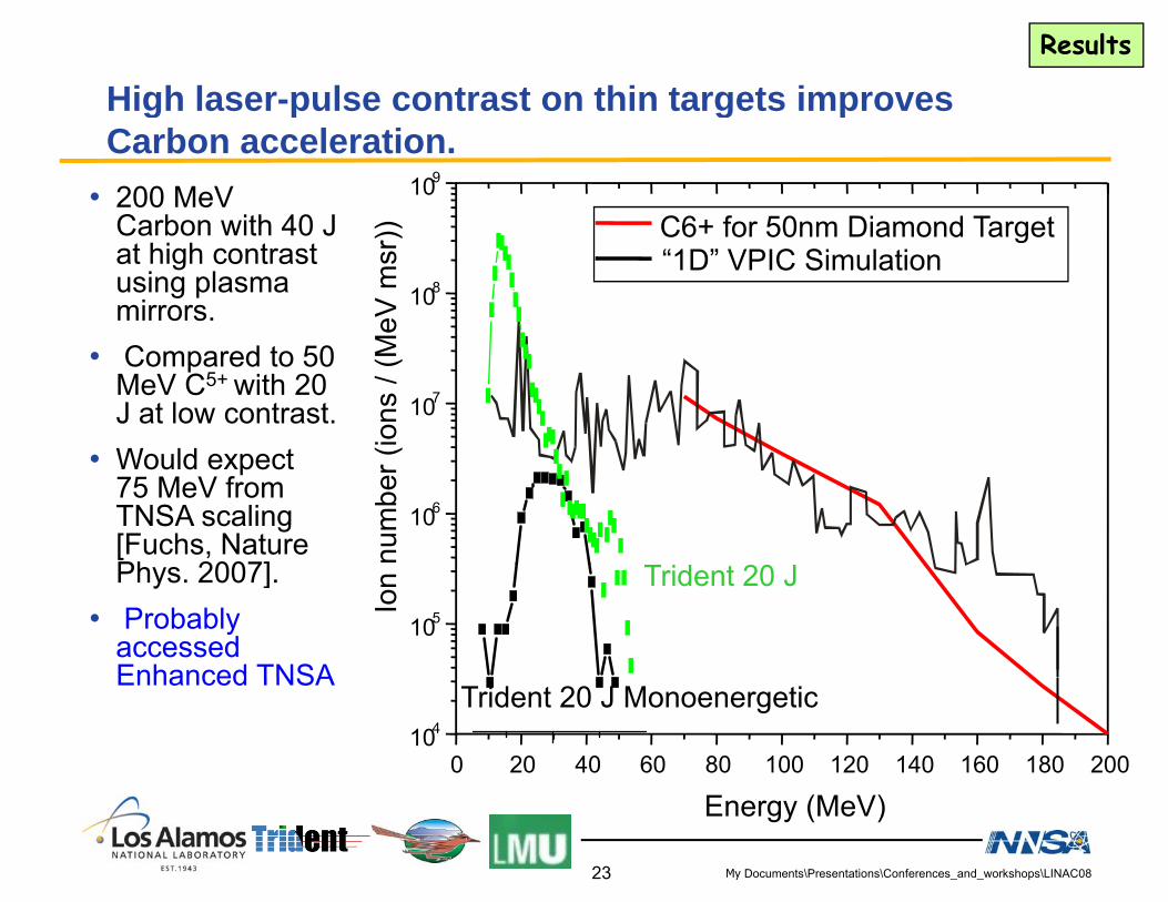
High laser-pulse contrast on thin targets improves Results
• 200 MeV Carbon with 40 J
g p g pCarbon acceleration.
109
) C6+ for 50nm Diamond TargetCarbon with 40 J at high contrast using plasma mirrors. 108
MeV
msr
)) C6+ for 50nm Diamond Target“1D” VPIC Simulation
• Compared to 50 MeV C5+ with 20 J at low contrast. W ld t
107(io
ns /
(M
• Would expect 75 MeV from TNSA scaling [Fuchs, Nature Ph 2007]
106
num
ber (
Phys. 2007].• Probably
accessed Enhanced TNSA
105Ion Trident 20 J
Enhanced TNSA
0 20 40 60 80 100 120 140 160 180 200104
Trident 20 J Monoenergetic
My Documents\Presentations\Conferences_and_workshops\LINAC08
Energy (MeV)
23
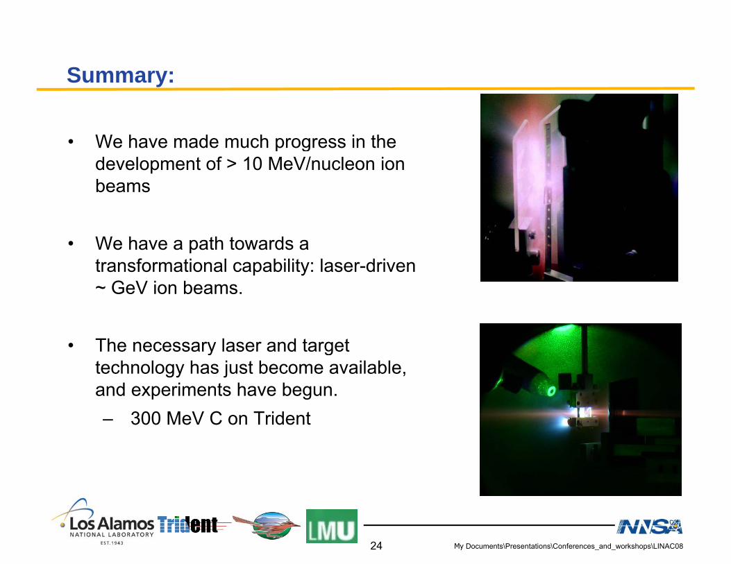
SSummary:
• We have made much progress in the• We have made much progress in the development of > 10 MeV/nucleon ion beams
• We have a path towards a transformational capability: laser-driven
G V i b~ GeV ion beams.
• The necessary laser and target y gtechnology has just become available, and experiments have begun.– 300 MeV C on Trident300 MeV C on Trident
My Documents\Presentations\Conferences_and_workshops\LINAC0824

Selected references for some identified ion acceleration mechanisms• Target Normal Sheath Acceleration (TNSA)
– Theory & Modeling: S P Hatchett et al Phys Plasmas 7 2076– Theory & Modeling: S. P. Hatchett, et al., Phys. Plasmas 7, 2076 (2000); S. Wilks, et al., Phys. Plasmas 8, 542 (2001);
– Experiments: R. A. Snavely, et al., Phys. Rev. Lett. Plasmas 85, 1945 (2000); T. E. Cowan, et al., Phys. Rev. Lett. 92, 204801 (2004); J. Fuchs, et al., Phys. Rev. Lett. 94, 045004 (2005); B. M. Hegelich, et al., Nature 439, 441 (2006)
• Radiation Pressure Acceleration (RPA), aka Plasma Piston– Theory: A.P.L. Robinson, et al., New J. Phys. 10, 013021 (2008); T.
Esirkepov, et al., Phys. Rev. Lett. 92, 175003 (2004); T. Esirkepov, et al., Phys. Rev. Lett. 96, 105001 (2006); G. Marx, et al., Nature 211 22 (1966)211, 22 (1966)
• Laser Break-Out After Burner (BOA)– Theory: L. Yin, et al., Laser Part. Beams 24, 291 (2006) ; L. Yin, et
l Ph Pl 14 056706 (2007) B J Alb i ht t l Phal., Phys. Plasmas 14, 056706 (2007); B. J. Albright, et al., Phys. Plasmas 14 (2007)
• Alfvénic solitonsTh B R d T T ji Ph Pl 10 3575 (1998)
My Documents\Presentations\Conferences_and_workshops\LINAC08
– Theory: B. Rau and T. Tajima, Phys. Plasmas 10, 3575 (1998)
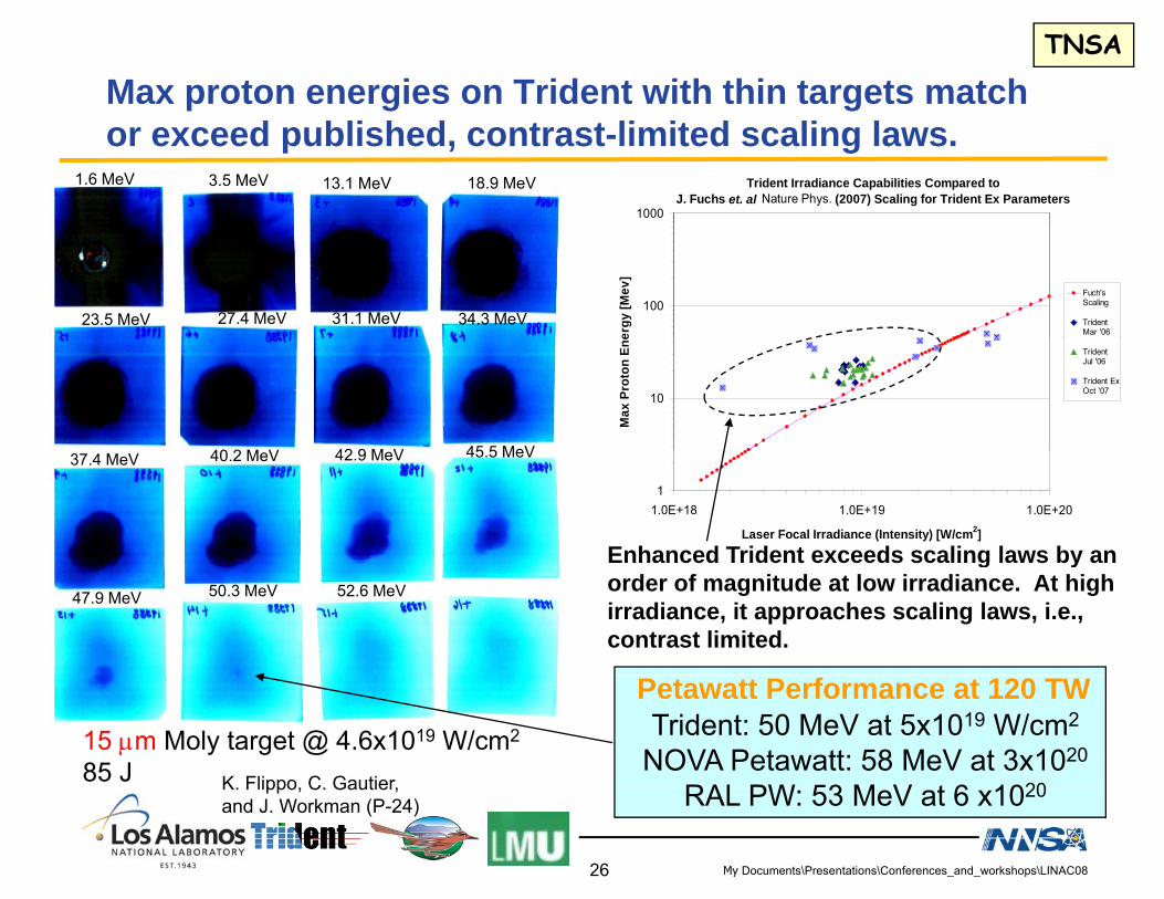
Max proton energies on Trident with thin targets match TNSA
or exceed published, contrast-limited scaling laws.Trident Irradiance Capabilities Compared to
J. Fuchs et. al Nature Phys. (2007) Scaling for Trident Ex Parameters1000
18.9 MeV13.1 MeV3.5 MeV1.6 MeV
100
ergy
[Mev
]
Fuch'sScaling
TridentMar '06
34.3 MeV31.1 MeV27.4 MeV23.5 MeV
10
Max
Pro
ton
Ene
TridentJul '06
Trident ExOct '07
45 5 MeV42 9 M V40 2 M V
11.0E+18 1.0E+19 1.0E+20
Laser Focal Irradiance (Intensity) [W/cm2]
Enhanced Trident exceeds scaling laws by an
45.5 MeV42.9 MeV40.2 MeV37.4 MeV
Enhanced Trident exceeds scaling laws by an order of magnitude at low irradiance. At high irradiance, it approaches scaling laws, i.e., contrast limited.
50.3 MeV47.9 MeV 52.6 MeV
15 μm Moly target @ 4.6x10¹⁹ W/cm2
85 J K Flippo C Gautier
Trident: 50 MeV at 5x10¹⁹ W/cm2
NOVA Petawatt: 58 MeV at 3x10²⁰
RAL PW 53 M V t 6 1020
Petawatt Performance at 120 TW
My Documents\Presentations\Conferences_and_workshops\LINAC08
K. Flippo, C. Gautier, and J. Workman (P-24) RAL PW: 53 MeV at 6 x10²⁰
26

Advanced, compact laser-driven ion accelerators may Background
• Fusion energy– Proton-driven fast ignition [M. Roth, et al. Phys. Rev.
, p yenable new scientific research and practical applications.
g [ , yLett. 86, 436 (2001); M. H. Key et al., Fusion Science & Technology 49, 440 (2006) 440; M. H. Key, Phys. Plasmas 14, 055502 (2007)]
– Light-ion FI [J. C. Fernández et al., J. Physics : Conf. Series 112 022051 (2008); B J Albright et al ibid 112Series 112, 022051 (2008); B. J. Albright et al., ibid 112, 022029 (2008); J.J. Honrubia et al., Hirschegg 2008 Workshop & 35th EPS Plasma Conference, 2008; , paper P-5.125; V. Yu. Bychenkov, Plasma Phys. Reports 27, 1017 (2001)]) Minimum beam ignition energy for a
C beam (δE/E ~ 10%) to ignite DT fuel • Detection of fissile materials
– Compact proton accelerators for active interrogation (DNDO, DTRA)
• Nuclear physics
core compressed to ρ= 500 g/cc with a size FWHM = 82 μm.
Nuclear physics– Particle production (e.g., pions [V. Yu. Bychenkov,
JETP 74, 586 (2001)])– Colliders, e.g., of short-lived particles (e.g., pions)
using high-luminosity, compact laser-driven proton and heavy ion beamsheavy ion beams
• Probe warm dense matter• Cancer tumor therapy using laser-driven affordable,
compact ion accelerators– Exploiting Bragg peak of low-Z (e g ) beams
My Documents\Presentations\Conferences_and_workshops\LINAC08
Exploiting Bragg peak of low-Z (e.g.) beams
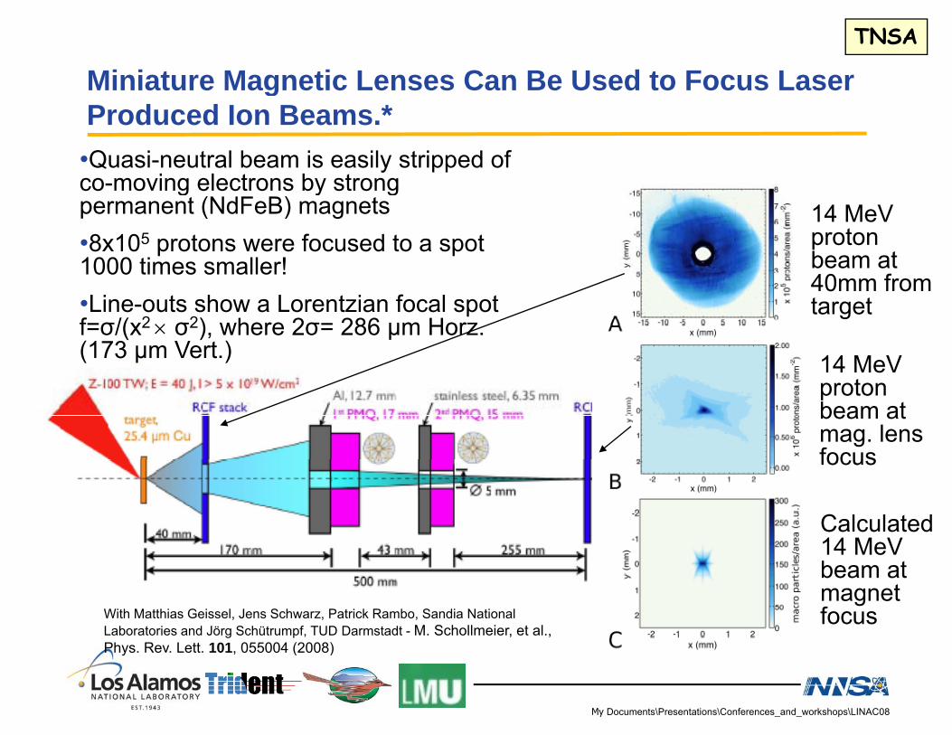
Miniature Magnetic Lenses Can Be Used to Focus Laser TNSA
gProduced Ion Beams.*•Quasi-neutral beam is easily stripped of co-moving electrons by strongco-moving electrons by strong permanent (NdFeB) magnets•8x10⁵ protons were focused to a spot 1000 times smaller!
14 MeV proton beam at 40 f
•Line-outs show a Lorentzian focal spot f=σ/(x2 × σ2), where 2σ= 286 µm Horz.(173 µm Vert.)
40mm from target
14 MeV14 MeV proton beam at mag. lens focusfocus
Calculated 14 MeV14 MeV beam at magnet focusWith Matthias Geissel, Jens Schwarz, Patrick Rambo, Sandia National
Laboratories and Jörg Schütrumpf, TUD Darmstadt - M. Schollmeier, et al., Ph R L tt 101 055004 (2008)
My Documents\Presentations\Conferences_and_workshops\LINAC08
Phys. Rev. Lett. 101, 055004 (2008)

3D i l ti f RPS C b l ti
Results
3D simulation of RPS Carbon acceleration
• VPIC has been modified to run efficiently on Roadrunner (Opteron hosted hybrid supercomputer with 12960 IBM Power Xcell 8i chips)•We anticipate an additional factor of ~10 in speed over Opteron, enabling routine trillion-particle PIC simulations•We have obtained a significant allotment of time (13 million hours, >1/3 of time when whole system is available) on the full 3 Pflop/s (single precision) Roadrunner system
My Documents\Presentations\Conferences_and_workshops\LINAC08
whole system is available) on the full 3 Pflop/s (single precision) Roadrunner system

High laser-pulse contrast on thin targets improves Results
g p g pCarbon acceleration.
• 180 MeV Carbon with 40 J at high contrast using plasma mirrors
C6+ spectrum from 30 nm diamond
cleaned W-C targe
plasma mirrors.• Compared to 50 MeV C5+ with 20 J at low contrast
target
at low contrast. • Expected 75 MeV from high contrast scalingcontrast scaling.
Trident 20 J
Trident 20 J Monoenergetic
My Documents\Presentations\Conferences_and_workshops\LINAC08

The ion beam focusing is influenced by target surface
TNSA
The ion-beam focusing is influenced by target-surface geometry and by the radial profile of the electric sheath.• Ballistic proton focusing has been demonstrated with hemi-shellBallistic proton focusing has been demonstrated with hemi shell
targets.*• Focus is beyond center of curvature due to divergence induced by
sheath radial profile.sheath radial profile.
Data from 250 J, 1 ps pulses at Gekko(from Snavely et al., Proc. IFSA 2003)
Measurement at JANUSP, LLNL
* Patel et al Phys Rev Lett 91 (2003) 125004
My Documents\Presentations\Conferences_and_workshops\LINAC08
Patel et al., Phys. Rev. Lett. 91 (2003) 125004
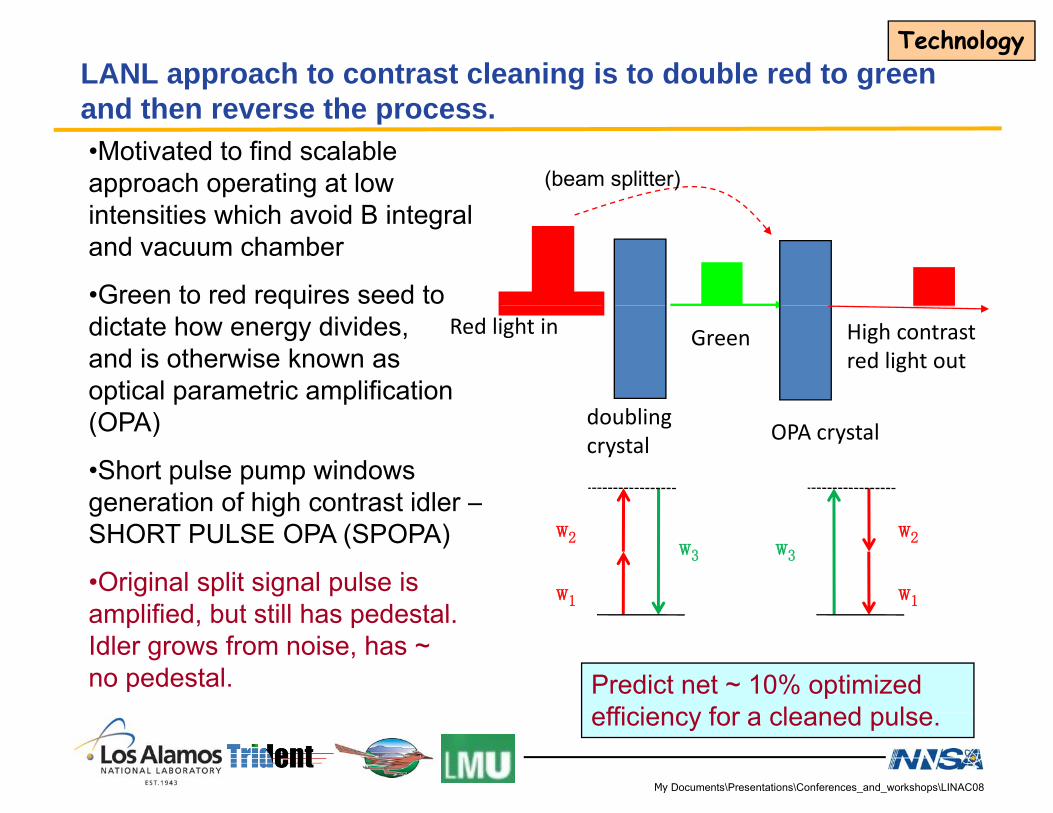
LANL approach to contrast cleaning is to double red to green d th th
Technology
and then reverse the process.•Motivated to find scalable approach operating at low (beam splitter)
intensities which avoid B integral and vacuum chamber
•Green to red requires seed to Red light in Green High contrast
red light out
qdictate how energy divides, and is otherwise known as optical parametric amplification
doublingcrystal OPA crystal(OPA)
•Short pulse pump windows generation of high contrast idler –
w1
w2w3
w1
w2w3
generation of high contrast idler SHORT PULSE OPA (SPOPA)
•Original split signal pulse is amplified but still has pedestalamplified, but still has pedestal. Idler grows from noise, has ~ no pedestal. Predict net ~ 10% optimized
efficiency for a cleaned pulse
My Documents\Presentations\Conferences_and_workshops\LINAC08
efficiency for a cleaned pulse.
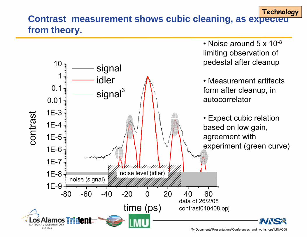
Contrast measurement shows cubic cleaning, as expected from theory
Technology
• Noise around 5 x 10⁻⁸
limiting observation of d l f l
from theory.
pedestal after cleanup
• Measurement artifacts form after cleanup in0 1
110 signal
idler3 form after cleanup, in
autocorrelator
• Expect cubic relation1E-30.01
0.1
st
signal3
• Expect cubic relation based on low gain, agreement with experiment (green curve)1E 6
1E-51E-4
cont
ra
experiment (green curve)
1E-81E-71E-6
noise level (idler)i ( i l)
-80 -60 -40 -20 0 20 40 601E-9 noise level (idler)noise level (idler)
time (ps)
noise (signal)
data of 26/2/08contrast040408 opj
My Documents\Presentations\Conferences_and_workshops\LINAC08
time (ps) contrast040408.opj

Target morphology:Technology
Improved TNSA via novel cone targets
Flared Flat-Top ConeTypical Target Shape and Dimensions
θt
200 μm
Flared Flat Top Cone
θn
μ
side
θt
θn= 15 -135 μm
top
My Documents\Presentations\Conferences_and_workshops\LINAC08
n μθt= 75 - 440 μm
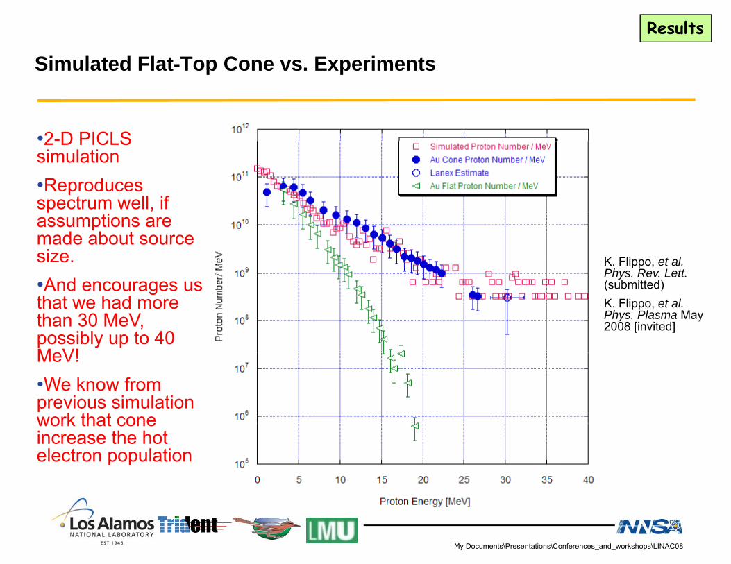
Simulated Flat-Top Cone vs. Experiments
Results
Simulated Flat Top Cone vs. Experiments
•2-D PICLS2 D PICLS simulation•Reproduces spectrum well, if passumptions are made about source size.•And encourages us
K. Flippo, et al. Phys. Rev. Lett.(s bmitted)•And encourages us
that we had more than 30 MeV, possibly up to 40 MeV!
(submitted)K. Flippo, et al. Phys. Plasma May 2008 [invited]
MeV!•We know from previous simulation work that conework that cone increase the hot electron population
My Documents\Presentations\Conferences_and_workshops\LINAC08

Trident Enh. Flat Foil50
Cone targets show excellent performance compared to
Results
Sim Cone target40
45Cone targets show excellent performance compared to flat foils.
30
35
Cone target
10
Trident Enh. Flat Foil
Cu target
Cu target
Cone target
(τlaser= 320 fs for protons > 4 MeV)Trident: τ =600 fs, I=1×10¹⁹ W/cm2
My Documents\Presentations\Conferences_and_workshops\LINAC08
From J. Fuchs et al., Nature Physics 1, 199 (2005)

Quasi-monoenergetic mid-Z ions have potential Q g padvantages as a fusion ignitor beam.
• Requirements for Inertial Fusion Energy:C d f l 500 /– Compressed fuel ~ 500 g/cc
– 10 kJ ignitor beam ranging within (~ 25 μm)3
– E.g., 1014 C ions at ~ 400 MeV
• Potential advantages over electron* or proton-based1 FI:– Monoenergetic ion source far from the fuel– Range is better matched (efficiency)– Sharp deposition (efficiency)– More robust ion-beam transport– Fewer particles required (easier target Fab.)
• Potential performance:– Fusion gain of 50-100, assuming laser-beam conversion efficiency of 10%2
* Tabak et al., PoP 1(1994) 16261 Roth et al., PRL 86 (2001) 436
My Documents\Presentations\Conferences_and_workshops\LINAC08
2 JJ. Honrubia et al., 2008 Hirschegg Wkshop
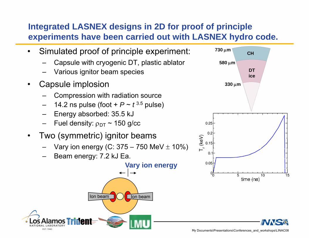
Integrated LASNEX designs in 2D for proof of principle g g p p pexperiments have been carried out with LASNEX hydro code.• Simulated proof of principle experiment: CH
730 μm
– Capsule with cryogenic DT, plastic ablator– Various ignitor beam species
• Capsule implosion
DTice
330 μm
580 μm
– Compression with radiation source– 14.2 ns pulse (foot + P ~ t 3.5 pulse)– Energy absorbed: 35.5 kJ– Fuel density: ρDT ~ 150 g/cc
• Two (symmetric) ignitor beams– Vary ion energy (C: 375 – 750 MeV ± 10%)Vary ion energy (C: 375 750 MeV ± 10%)– Beam energy: 7.2 kJ Ea.
Vary ion energy
Ion beam Ion beam
My Documents\Presentations\Conferences_and_workshops\LINAC08
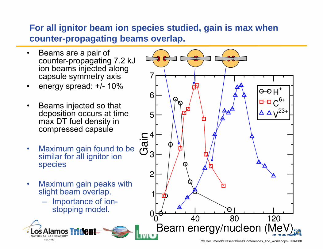
For all ignitor beam ion species studied, gain is max when g p , gcounter-propagating beams overlap.
• Beams are a pair of counter-propagating 7 2 kJcounter propagating 7.2 kJ ion beams injected along capsule symmetry axis
• energy spread: +/- 10%
• Beams injected so that deposition occurs at time max DT fuel density in ycompressed capsule
• Maximum gain found to be similar for all ignitor ionsimilar for all ignitor ion species
• Maximum gain peaks with g pslight beam overlap.– Importance of ion-
stopping model.
My Documents\Presentations\Conferences_and_workshops\LINAC08
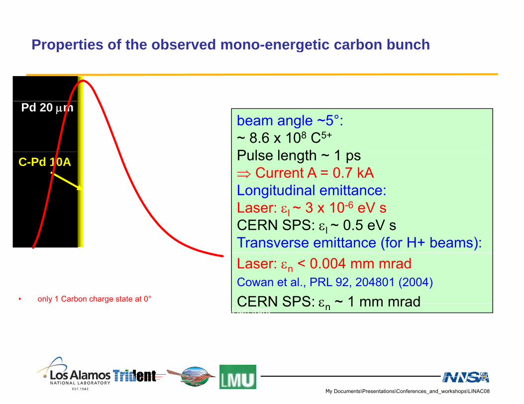
Properties of the observed mono-energetic carbon bunchp g
Pd 20 μmbeam angle ~5°:~ 8.6 x 10⁸ C5+
P l l th 1C-Pd 10A Pulse length ~ 1 ps⇒ Current A = 0.7 kALongitudinal emittance:L 3 10 6 VLaser: εl ~ 3 x 10⁻⁶ eV sCERN SPS: εl ~ 0.5 eV sTransverse emittance (for H+ beams):Laser: εn < 0.004 mm mradCowan et al., PRL 92, 204801 (2004)
CERN SPS: ε ~ 1 mm mrad• only 1 Carbon charge state at 0° CERN SPS: εn 1 mm mrad⇒ i.e. no recombination occurs within the fast ion front⇒ Low charge states at 0° have to be created at late times by a decaying field or stem from beneath the surface
My Documents\Presentations\Conferences_and_workshops\LINAC08

Beam parameters; Results
comparison with typical C-spectrum
Mono-energetic Beam:SA ~ 65 msrdN ~ 8.6 x 10⁸ C5+
Etot ~ 5 mJ107
C5+, #147, Elaser=17J C4+, #84, Elaser=17J
srd-1
]
totCtot ~ 0.7 nCCE ~ 0.03 %1.5x10⁶
s [M
eV-1 m
s
Maxwellian Beam (same energy range):SA ~ 65 msrd5.0x105
1.0x10⁶
Ionc
ount
s
SA 65 msrdN ~ 4 x 10⁸ C4+Etot ~ 2 mJCt t ~ 0 26 nC
0.0 0.5 1.0 1.5 2.0 2.5 3.0 3.5 4.0Energy / nucleon [MeV/u] Ctot 0.26 nC
CE ~ 0.01 %• Factor 2 increase in the number of high energy ions• Factor 2.5 increase in energy content and conversion efficiency• Factor 3 increase in beam current
My Documents\Presentations\Conferences_and_workshops\LINAC08

Successful low- and mid-Z ion acceleration at Trident
Results
8
109
F7+d)]
Trident
beam angle ~10°: ~1.8x10⁹ Pd22+ with E > 1
105
106
107
108
F O6+
C4+
Be4+
Ions
[1 /
(MeV
msr
d
1010 Σ 22 1918
Palladium1.8x10 Pd with E 1
MeV/u.
Etotal,Pd22+(1MeV/u) ~ 0 1 2 3 4 5 6
104
Energy / nucleon [MeV]
107
108
10918 15 13 12 10 9 7[M
eV-1 m
srd-1
]total,Pd22+( )38mJ ⇒ conversion efficiency ηPd22+(1MeV/u) ~ 0.2%.
105
106
10 6 5 4
Ionc
ount
s [
total #Pd22+ ~ 2.4x10¹⁰, Etotal, Pd22+ ~ 184mJ ⇒
1 1%1 10 100
104
Energy [MeV]
ηPd22+ ~1.1%.
The conversion efficiency for laser energy into Pd-for laser energy into Pd-ions of any charge state is on the order of a few %.
My Documents\Presentations\Conferences_and_workshops\LINAC08
Laser
• NovaNova PW
Laser
– Nova PW
My Documents\Presentations\Conferences_and_workshops\LINAC08
Recommended