Laser Beam StabilizationCompact
Always perfectly aligned.

Since more than 20 years we develop, produce and sell our innovative products for various fields in laser and medical technology.
MRC Systems GmbH was founded in 1995 as a spin-off of the University of Heidelberg and the German Cancer Research Center (DKFZ). MRC is an independent company with its principal office in Heidelberg, Germany.
Our technical developments benefit from our ambitious and experienced staff in the fields of optics and laser technology, electronic engineering, software development and mechanical design as well as registration and certification.
With our innovative strength, precision and reliability we became a leading innovator in different product areas. We always focus on the ideal solution for the end user.
We established long-term cooperations with many universities, research institutes and manufacturing partners. Our products are designed for international markets and are in use all over the world, often in permanent 24/7 operation.
We guarantee our customers high quality products and offer our comprehensive service over the complete product lifecycle. We introduced a total quality management system in 1998 and continuously refine it. All our processes are DIN EN ISO 13485 certified.
We are looking forward to hear from you and your specific task and would be pleased to assist you in your projects.
Made in Germany We are looking forward to hear from you!
Our customers across the world
2
Heidelberg / Germany

Our laser beam stabilization system should be used in all applications where a reliable beam pointing stability is required. It ensures a very stable and precise beam position and direction.
The closed-loop system works in real-time and eliminates all kinds of deviations caused by thermal drifts, vibrations or other mechanical impacts. It can even compensate for effects with high frequencies like air fluctuations, shocks or moving optics.
The beam stabilization makes use of three main components: Beam position detectors with highest resolution, very fast and robust Piezo-actuated mirror mounts, and a closed-loop controller.
Due to its analog core the system's overall resolution is not limited by sampling rates, latencies or digitizing steps. With the experience of more than ten years in the field, it ensures an optimal performance with almost all kinds of lasers.
The desired position and angle of the laser beam is defined by one or two detectors (4-quadrant-diodes or PSDs). For the detection, a small portion of the laser power transmitted through a high-reflective deflection mirror is sufficient.
The closed-loop controller continuously determines the deviation of the laser beam from the target position. The system continuously drives the Piezo actuated mirrors into the required positions to compensate for the deviations.
A typical setup is shown in the figure below, where two actuators and two detectors are used to stabilize the beam in four dimensions (4D).
In this setup, the first stage of actuator 1 / detector 1 maintains a stable position on actuator 2. Then the second stage of actuator 2 / detector 2 guarantees the correct beam direction for the application. The modular design of the system's components supports a big number of alternative setups. Some of them are shown on pages 6-7.
Laser beam stabilization
Principle of laser beam stabilization
3
detector 1
laser
actuator 1
actuator 2
detector 2
application
mechanicalshocks
driftsfluctuations
vibrations
stabilization OFF stabilization ON

Compact systemAutomatic position and direction control of laser beams in real-time
Your advantages
✔The Compact system ensures that you always have a stable beam position and direction.
✔You will reach the highest precision in your application.
✔ You can be sure that your alignment stays stable over time.
✔ Simply insert the components into your setup, stop investing time in realignment procedures.
Features● Highest precision: No latencies and no digitizing
steps due to the analog real-time core.
● No time consuming parameter settings and no computer required.
● No beam splitters required since the detectors can use the leakage behind your mirrors.
● Easy to integrate into existing set-ups by just exchanging the mirror mounts.
4
Specifications● All wavelengths: 190 nm to 3000 µm, even THz
(standard detector: 320 nm to 1100 nm)
● All repetition rates: from single pulses to cwall pulse durations (as, fs, ps, ns, …)
● Large dynamic range: intensity variations by a factor of > 1000 with optional WID detector
● High speed control: continuous signal processing, no sampling delays
● Resolution / Accuracy: < 0.1 µm; < 0.1 µrad (down to 10 – 100 nm)
● Mirror diameters: 0.5 to 4 inch (other sizes on request)
Selected functions Selected options● Power level and position display directly on the
backside of the detectors
● Variable gain control
● Various signal in- and outputs
● Manual coarse adjustment of mirror mounts
● Sample-and-hold circuit for applications with single laser pulses or low repetition rates
● Variable target position adjustment
● Vacuum components, down to 10-11 mbar
● External activation, RS 232 interface, ...

System components (selection)
Piezo-driven mirror actuators
Si 4-QD PSD Wide-Intensity 4-QD
wavelength 320 - 1100 nm 320 – 1100 nm 320 – 1100 nm
detection area 10 x 10 mm2 9 x 9 mm2 10 x 10 mm2
features highest lateral resolution
adjustable target position
large intensity range factor > 1000
Broadband detectors
Special detectors
UV 4-QDSi PIN
IR 4-QD InGaAs
IR 4-QD Germanium
Pyroelectric4-QD
wavelength 190 - 1000 nm 900 – 1700 nm 800 – 1800 nm 0.1 – 3000 µm
detection area 3 x 3 mm2 Ø = 3 mm Ø = 5 mm 9 x 9 mm2
features sensor for UV lasers
sensor for NIR lasers
sensor for NIR lasers
UV, vis, IR sensor
Detectors for all wavelengths
P4S30 PSH PKS
features highest performance high performance small size
best for larger mirrors up to 3''
leakage behind the mirror can be used for the detection
mechanical tilt 4 mrad(± 2 mrad)
2 mrad(± 1 mrad)
1 mrad(± 0.5 mrad)
optical tilt 8 mrad(± 4 mrad)
4 mrad(± 2 mrad)
2 mrad(± 1 mrad)
PSH with 1'' mirror
P4S30 with 1.5'' mirror
PKS with 1'' mirrorPSH for vacuum
5
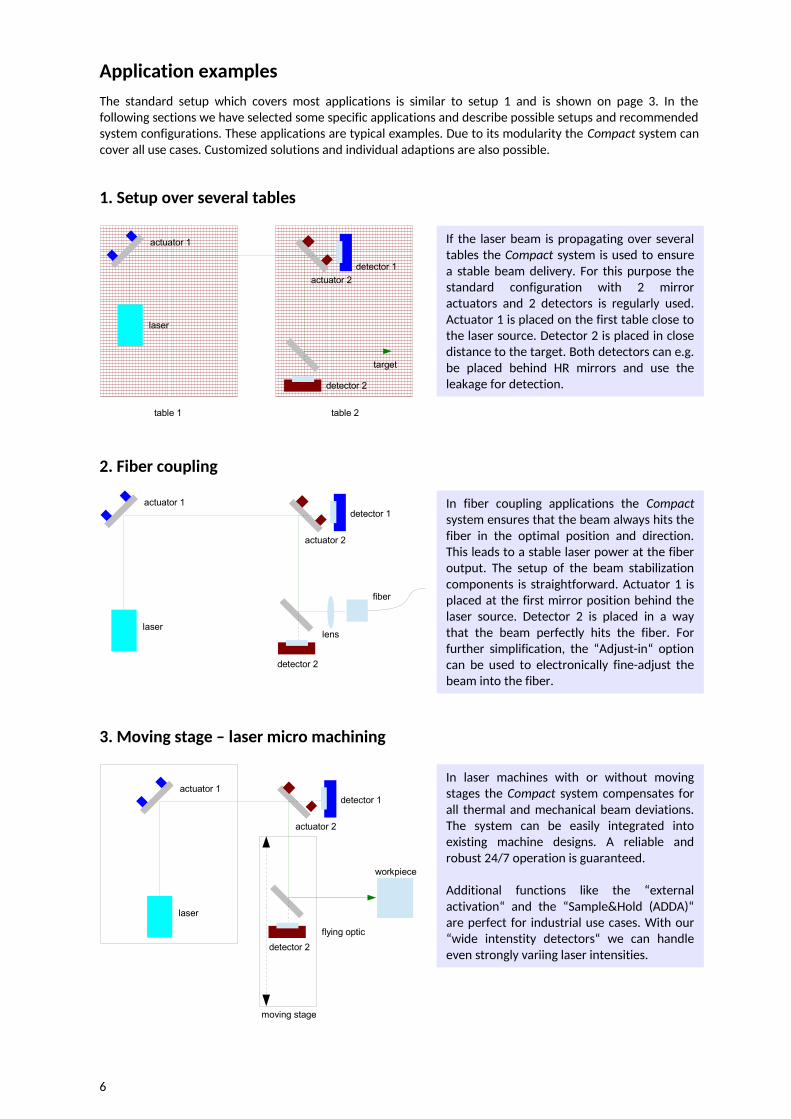
If the laser beam is propagating over several tables the Compact system is used to ensure a stable beam delivery. For this purpose the standard configuration with 2 mirror actuators and 2 detectors is regularly used. Actuator 1 is placed on the first table close to the laser source. Detector 2 is placed in close distance to the target. Both detectors can e.g. be placed behind HR mirrors and use the leakage for detection.
Application examples
1. Setup over several tables
moving stage
laser
actuator 1
actuator 2
detector 1
detector 2
flying optic
workpiece
3. Moving stage – laser micro machining
2. Fiber coupling
laser
actuator 1
actuator 2
detector 1
fiber
lens
detector 2
detector 1
table 1 table 2
laser
actuator 1
actuator 2
detector 2
target
In fiber coupling applications the Compact system ensures that the beam always hits the fiber in the optimal position and direction. This leads to a stable laser power at the fiber output. The setup of the beam stabilization components is straightforward. Actuator 1 is placed at the first mirror position behind the laser source. Detector 2 is placed in a way that the beam perfectly hits the fiber. For further simplification, the “Adjust-in“ option can be used to electronically fine-adjust the beam into the fiber.
In laser machines with or without moving stages the Compact system compensates for all thermal and mechanical beam deviations. The system can be easily integrated into existing machine designs. A reliable and robust 24/7 operation is guaranteed.
Additional functions like the “external activation“ and the “Sample&Hold (ADDA)“ are perfect for industrial use cases. With our “wide intenstity detectors“ we can handle even strongly variing laser intensities.
The standard setup which covers most applications is similar to setup 1 and is shown on page 3. In the following sections we have selected some specific applications and describe possible setups and recommended system configurations. These applications are typical examples. Due to its modularity the Compact system can cover all use cases. Customized solutions and individual adaptions are also possible.
6

5. Set-up with 4D detector
laser
actuator 1
actuator 2
detector 2
detector 1
target
6. Remote fine adjustment
laser
actuator 1
actuator 2
PSD detector 1
PSDdetector 2
target
4. Pump probe experiment
One or more beams of a pump probe experiment can be stabilized. In our example only the probe beam with the delay line is stabilized. Two actuator and detector pairs compensate for the deviations of the delay stage and ensure that the probe beam exactly hits the target.
If necessary a second system can be applied to stabilize the pump beam, too.
In some cases it is advantageous to place both detectors close to the target. This approach is also possible with the Compact system.
The detectors measure both, the beam position and the direction at the same point. A lens is placed in front of detector 2 which discriminates for the angle.
For stabilization tasks where the components are hard to reach or for applications with moving target points, we recommend the optional “Adjust-in” function. It is usually combined with PSDs instead of 4-quadrant diodes (4-QDs). A PSD allows to freely define the target position on its sensitive area while a 4-QD uses the center of 4 quadrants.
With the “Adjust-in” function the target position on the PSDs can be chosen electronically. This allows to fine adjust the beam position without manual interventions and to change the target position during operation.
7
detector 2probe laser
actuator 1
detector 1
delay line
target
actuator 2
v
pump laser
lens
beam splitter

MRC Systems GmbHHans-Bunte-Str. 8-10
69123 HeidelbergGermany
Phone: +49 (0) 6221 13 80 300Fax: +49 (0) 6221 13 80 301
Email: [email protected]: www.mrc-systems.de M
RC
-06
17-2
00-1
-eC
ove
r ph
oto
: Cra
ne
and
jet -
in th
e a
ir b
y P
ete
r D
am
Recommended