Geospatial Technology & Applications Center |Lidar Acquisitions Specifications for Forestry | 1
National Lidar Strategy January, 2018
Lidar Acquisition Specifications for Forestry Applications
Geospatial Technology & Applications Center 2222 West 2300 South Salt Lake City, Utah 84119-2020 RSAC intranet website: http://fsweb.rsac.fs.fed.us/
Brent Mitchell Contract Lead Geospatial Applications and Training RedCastle Resources, onsite contractor 801-975-3459, [email protected]
Haans Fisk Program Leader Resource Application and Technology Implementation (RATI) 801-975-3750, [email protected]
Jess Clark Assistant Program Leader Resource Application and Technology Implementation (RATI) 801-975-3769, [email protected]
Eric Rounds Remote Sensing Specialist and Trainer RedCastle Resources, onsite contractor 801-975-3771, [email protected]

Geospatial Technology & Applications Center |Lidar Acquisitions Specifications for Forestry | 2
Table of Contents Background ................................................................................................................................................ 3
Recommended Lidar Specifications ........................................................................................................... 4
Information for Vendor ............................................................................................................................. 5
Lidar Derived Products .............................................................................................................................. 6
Summary .................................................................................................................................................... 7
References ................................................................................................................................................. 8
Appendix – Statement of Work ................................................................................................................. 9
Geospatial Technology & Applications Center |Lidar Acquisitions Specifications for Forestry | 3
Background In order to effectively support many natural resource management decisions, the USDA Forest Service
(USFS) requires information about the vertical and horizontal structure of vegetation and the underlying
terrain. Light Detection and Ranging (lidar) provides unique three dimensional (3-D) information that
simultaneously measures the ground surface and forest canopy structure across acquisition areas in a
comprehensive and accurate way that no other remote sensing technology currently offers. Based on
the capability to provide detailed 3-D information, lidar is being used more frequently in forestry
applications (e.g., forest inventories, engineering operations, and habitat modeling).
The primary obstacle to acquiring new lidar data is the cost. To mitigate this, many federal government
agencies have formed consortia with state and local government, as well as academic and research
institutions to share acquisition costs. The most notable large scale effort is the 3D Elevation Program
(3DEP) spearheaded by the United States Geological Survey (USGS). The USGS has collaborated with
other federal agencies to initiate 3DEP in response to the growing needs for high-quality topographic
data and other lidar derivatives.
The primary goal of 3DEP is to systematically collect lidar for high-quality topographic information in an
eight year period over the conterminous United States, Hawaii, and the U.S. territories (USGS 3DEP
website: http://nationalmap.gov/3DEP/). The USGS Lidar Base Specification document
(http://pubs.usgs.gov/tm/11b4/) details four quality levels (QL) that define minimum acceptable
parameters of the lidar data and are intended to help provide consistency among partner-funded lidar
collections, especially for 3DEP and the National Elevation Dataset (NED). As USFS budgets erode and
more agencies are interested in partnering to acquire lidar, it only makes sense to view forestry
acquisition specifications through the 3DEP defined QL’s (e.g., table 1).
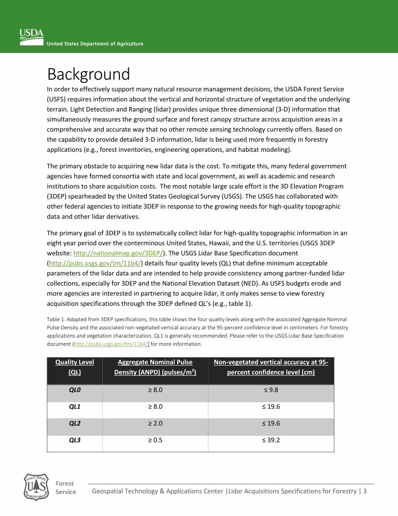
Table 1. Adapted from 3DEP specifications, this table shows the four quality levels along with the associated Aggregate Nominal
Pulse Density and the associated non-vegetated vertical accuracy at the 95-percent confidence level in centimeters. For forestry
applications and vegetation characterization, QL1 is generally recommended. Please refer to the USGS Lidar Base Specification
document (http://pubs.usgs.gov/tm/11b4/) for more information.
Quality Level
(QL)
Aggregate Nominal Pulse
Density (ANPD) (pulses/m2)
Non-vegetated vertical accuracy at 95-
percent confidence level (cm)
QL0 ≥ 8.0 ≤ 9.8
QL1 ≥ 8.0 ≤ 19.6
QL2 ≥ 2.0 ≤ 19.6
QL3 ≥ 0.5 ≤ 39.2
Geospatial Technology & Applications Center |Lidar Acquisitions Specifications for Forestry | 4
Partnership funding for 3DEP lidar acquisition projects is available through the USGS Broad Agency
Announcement (BAA) (http://nationalmap.gov/3DEP/). Interested parties can contribute funds toward a
USGS lidar acquisition activity via the Geospatial Products and Services Contracts (GPSC), or
alternatively, they can request 3DEP funds go toward a lidar data acquisition activity when the USFS is
the acquiring authority. However, while partnerships provide a way to stretch agency dollars, we need
to remain cognizant that partnering may necessitate compromising on acquisition specifications and
could in turn diminish the value of the resulting data products. Therefore, it is important that USFS users
are abreast of the appropriate acquisition specifications for their desired applications. To support USFS
users with this, we address the following three primary objectives in this document:
Review recommended lidar specifications for forestry applications;
Describe products that are typically delivered by the vendor and those that can be created from lidar data; and
Provide an example Statement of Work from a recent USFS lidar acquisition (Appendix)
Recommended Lidar Specifications Acquisition specifications are heavily influenced by the intended application (e.g., topographic analysis
vs. forest inventories). Therefore, specifications should be developed after careful planning and
evaluation of project needs, while considering budgets, partnerships, and intended use of the lidar data.
As such, acquisition planning is challenging and often entails tradeoffs. However, loosening certain
specifications may impact the utility of the lidar data and should be carefully considered. This section
highlights recommended specifications for forestry applications and considers the potential impact of
specific parameters to the final products.
The four 3DEP quality levels provide consistency among the USGS and partners to acquire and use lidar
for 3DEP applications (table 1). It should be noted that the 3DEP QL’s are specifically designed to
support high-quality topographic data, not specifically vegetation characterization. As such, the
minimum acceptable 3DEP QL for vegetation characterization is QL2 (ANPD of 2 pulses/m2). However, to
accurately quantify tree heights, forest structure, and forest inventory parameters using lidar, the
research community generally agrees that at least an ANPD of 4 pulses/m2 is necessary (Reutebuch &
McGaughey, 2008). For this reason, in most cases, QL1 (ANPD of 8 pulses/m2) provides the ideal
specifications for forestry related acquisitions.
In addition to pulse density, other notable acquisition specifications that are recommended for lidar
acquisitions focused on forestry applications include: a narrow beam divergence, a scan angle of ≤13°,
50% side lap, opposing flight lines and a higher pulse frequency. Narrow beam divergence settings
provide more accurate tree-height information (Gatziolis and Andersen, 2008) and a higher percentage
of ground returns. Scan angle is important for forestry applications, because a higher scan angle
increases the distance a pulse must travel through the canopy before reaching the ground surface. This
can reduce the number of ground returns and the accuracy of elevation and height measurements. A
Geospatial Technology & Applications Center |Lidar Acquisitions Specifications for Forestry | 5
scan angle of ≤13° increases the probability that the lidar pulse will penetrate heavy forest cover and
adequately sample the forest structure. Keep in mind, however, a narrower scan angle increases the
number of flight lines required and in turn increases cost (Andersen et al, 2006). Sidelap refers to how
much overlap exists between scanning swaths. Fifty percent sidelap provides 100% total overlap, so
each area is being scanned twice. Ensuring 100% sidelap in conjunction with opposing flight lines is
crucial for forestry acquisitions to eliminate data occlusions (data shadows) from vegetated areas.
One final consideration is that 3DEP acquisitions are often flown during “leaf-off” conditions because the
main focus is on efficiently acquiring topographic (e.g., bare earth) products. Therefore, if you are
partnering with 3DEP for an acquisition, you may consider negotiating for “leaf-on” conditions during
the acquisition if obtaining forest structure is imperative to your project. If leaf-off data is your only
option you will still be able to obtain canopy height information, but canopy cover and density values
will be negatively skewed in deciduous canopies. All the considerations mentioned above are outlined
in more detail in Section 5 of the Appendix (pg. 13-14).
Information for Vendor The first step in working with a vendor is communicating what they need to know in order to fulfill your
data requirements. In addition to typical specifications for the lidar acquisition, it is important to clearly
communicate items that should be included in the contract and with the delivery in order to acquaint
the vendor with project-specific requirements. Such items include:
The location of the acquisition area, including a narrative, maps, and shapefile(s)
Potential problems the vendor needs to be aware of, such as flight-restricted areas and ground access
The lidar survey specifications (Section 5 of the Appendix) o Data-acquisition parameters o Accuracy specifications o Completeness and consistency of the data set o Spatial reference framework (datum, projections, units, etc.) o Deliverables o Formats and data organization (consistent file names, accessible file formats)
Time frame for data acquisition and delivery
Contact information for communication between vendor, client and local points of contact
Insurance/liability clauses
Contract nullification conditions
Data ownership
For a more complete look at what to include in a contract, an example Statement of Work for an actual
lidar acquisition is included in the Appendix.
Geospatial Technology & Applications Center |Lidar Acquisitions Specifications for Forestry | 6
Lidar Derived Products Airborne lidar surveys generate data-rich point clouds made up of millions/billions of points that
represent the world in a collection of x, y and z coordinates. To extract useful geospatial information
from the point cloud, filtering and classification algorithms are used to generate additional geospatial
products, or “lidar derived products,” from the raw point clouds. The lidar derived products provide 3-
D information (typically in raster format) across large landscapes to land managers that were not
available prior to the collection and manipulation of the point cloud. Below we have categorized lidar
derived products into three categories based on which data source it was derived from and who
would typically derive it. These categories are designed to assist potential users in understanding how
products are generated and what level of effort is typically involved to create them, they include: 1.
Point cloud derived products (vendor created), 2. Raster derived products (client created) and 3. Point
cloud derived products (client created).
1. Point Cloud Derived Products (vendor created):
Typical acquisitions (as specified by the Statement of work, see Appendix) include a few of the most
commonly used lidar products to be derived and delivered by the vendor in addition to the raw point
cloud. The products typically delivered by the vendor are ready to be used as is in a GIS and do not
require point cloud processing.
Bare earth surface model: a high resolution (1 meter) Digital Elevation Model (DEM) that
provides improved topographic information and 3-D viewing of the landscape. It is generated by
filtering the raw point cloud to identify “ground returns” and then creating a bare earth surface
from the filtered points. Note: It is highly recommended that you pay the lidar vendor to
generate this product; in most cases it is a cost savings.
Highest hit (first return) surface model: derived by creating a surface from the first return of
each pulse. It is essentially a 3-D model of all objects on the surface of the earth such as trees,
buildings, and infrastructure superimposed on the topography. It contains elevation values
above sea level rather than “height” above ground. The highest hit surface provides a realistic
3-D model of the complete environment.
Intensity image: derived from the amount of infrared energy reflected back to the sensor in
each lidar return. This information can be turned into an intensity image, which is a high-
resolution image (typically 1 meter) with values corresponding to a normalized infrared
reflection (similar to an orthophoto) and is typically used for qualitative analysis and reference
imagery.
2. Raster Derived Products (client created):
The following layers can be derived from the vendor delivered raster products using basic GIS analysis
and do not require further point cloud processing.

Geospatial Technology & Applications Center |Lidar Acquisitions Specifications for Forestry | 7
Canopy height model: derived by subtracting the bare earth surface model from the highest hit
surface model. This results in canopy and tree height above the ground in forested areas along
with the height of other objects in non-forested areas (bridges, powerlines, buildings etc.).
Hillshade model (bare earth, canopy height and highest hit): a black and white rendering that
highlights elevation/height changes in the landscape. The surface is illuminated by a
hypothetical light source, making elevation/height changes easier to visualize.
3. Point Cloud Derived Products (client created):
To further exploit the lidar data, there are a number of forest composition metrics – referred to as “first
order lidar metrics” – that can be derived from the raw point cloud to explain the canopy structure in
terms of height, cover and density statistics (McCallum et al., 2014; Mitchell et al., 2015). A complete list
of canopy structure metrics that can be generated from the point cloud are described in the FUSION
software manual (http://forsys.sefs.uw.edu/fusion/FUSION_manual.pdf). In addition, RSAC has
compiled “First Order Lidar Metrics: A Supporting Document for Lidar Deliverables”
(http://www.fs.fed.us/eng/rsac/lidar_training/pdf/LidarMetricsDescriptionOfDeliverables_Generic_12_
15_14.pdf) to aid USFS staff in confidently characterizing forest canopy structure.
Height metrics: A number of statistics are produced that describe the canopy height at a
specified scale (grid cell size). These metrics include basic distribution statistics such as the
mean, mode, variance and maximum height values among many others.
Cover metrics: This group of statistics includes different measurements of canopy cover and
canopy density. Canopy cover is calculated by taking a ratio of first returns above a height
threshold divided by the total number of first returns. This is comparable to photo interpreted
estimates of canopy cover but more consistent across large landscapes. Canopy density is
calculated by taking the ratio of all returns above a height threshold divided by the total number
of all returns.
Summary The lidar acquisition specifications needed to characterize the forest structure are provided in this
document, therefore it is up to the user to work with partners to create a Statement of Work that
captures the necessary specifications. 3DEP provides an ever increasing opportunity to collaborate on
lidar acquisitions and share costs, but you must be aware of the four QL’s and understand that not all of
the levels will meet forestry application needs. For further information or lidar acquisition consultation,
please contact your Regional Remote Sensing Coordinator or the Geospatial Technology and
Applications Center, and they will assist you in taking full advantage of the lidar resources available to
you.
Geospatial Technology & Applications Center |Lidar Acquisitions Specifications for Forestry | 8
References Andersen, H.E.; McGaughey, R.J.; Reutebuch, S.E. 2005. Estimating canopy fuel parameters using
airborne LIDAR data. Remote Sensing of Environment. 94: 441-449.
Gatziolis, Demetrios; Andersen, Hans-Erik. 2008. A guide to LIDAR data acquisition and processing for
the forests of the Pacific Northwest. Gen. Tech. Rep. PNW-GTR-768. Portland, OR: U.S. Department of
Agriculture, Forest Service, Pacific Northwest Research Station. 32 p
McCallum, K; Beaty, M; Mitchell, B. 2014. First Order Lidar Metrics: A Supporting Document For Lidar
Deliverables. Salt Lake City, UT: U.S. Department of Agriculture, Forest Service, Remote Sensing
Applications Center.
McGaughey, R.; Andersen, H-E.; Reutebuch, S. 2006. Considerations for planning, acquiring, and
processing lidar data for forestry applications. In Proceedings of the eleventh Forest Service remote
sensing applications conference, April 24–28, 2006, Salt Lake City, UT. Bethesda, Maryland: American
Society of Photogrammetry and Remote Sensing. Unpaginated CD-ROM.
Mitchell, B.; Beaty, M.; Reynolds, R.; Mellin, T.; Hudak, A.T.; Schaaf, A.; Fisk, H. 2015. Creating lidar
canopy structure layers and inventory models for evaluating northern Goshawk habitat quality. RSAC-
10070-RPT1. Salt Lake City, UT: U.S. Department of Agriculture, Forest Service, Remote Sensing
Applications Center. 21 p.
Reutebuch, S.E.; McGaughey, B. 2008. Airborne laser scanning (lidar): an emerging tool for multiple
resource measurement, planning and monitoring. Western Forester. 53(2): 1-5.
Reutebuch, S.E.; Andersen, H-E.; McGaughey, R.J. 2005. Light detection and ranging (lidar): An emerging
tool for multiple resource inventory. Journal of Forestry 103(6): 286–292.

Geospatial Technology & Applications Center |Lidar Acquisitions Specifications for Forestry | 9
Appendix – Statement of Work [Note: Replace green text with project-specific information]
Solicitation _______
Lidar Acquisition
Four Forests Restoration Initiative (4FRI) 2nd EIS Phase 2
Apache-Sitgreaves National Forests
USDA Forest Service Southwestern Regional Office
Albuquerque, NM
1) STATEMENT OF WORK
The purpose of this task is to:
a. Acquire lidar data for the Phase 2 of the 2nd EIS area for the Four Forests
Restoration Initiative (4FRI) on the Apache-Sitgreaves National Forests
located in Arizona.
b. Process and deliver the lidar data to the Southwestern Regional Office Remote
Sensing Unit (Contact information below.)
The contractor shall provide all equipment, labor, and materials necessary to map forest
structure within the ponderosa pine, mixed-conifer, and pinyon-juniper forest types using
Light Detection and Ranging (lidar) technology. The project area covers Phase 2 of the
2nd EIS area of the 4FRI project as well as additional acreage of FS lands extending to the
forest boundary on the Sitgreaves National Forest in Arizona. The data will be used
primarily to identify areas for implementation of forest restoration treatments designed to
restore resiliency and sustainability to frequent-fire forest types.
The vast majority of the technical specifications for this document were borrowed from
the Specifications outlined by the Oregon Lidar Consortium in their Lidar specifications
document. The Data Quality Assurance procedures were developed by the Remote
Sensing Applications Center.
2) TECHNICAL SPECIFICATIONS
4FRI 2nd EIS Phase 2 acquisition specs
1. Acquisition Area:
Geospatial Technology & Applications Center |Lidar Acquisitions Specifications for Forestry | 10
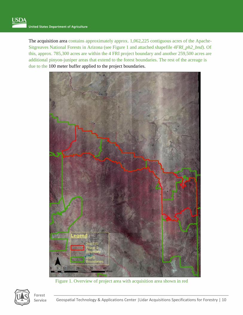
The acquisition area contains approximately approx. 1,062,225 contiguous acres of the Apache-
Sitgreaves National Forests in Arizona (see Figure 1 and attached shapefile 4FRI_ph2_bnd). Of
this, approx. 785,300 acres are within the 4 FRI project boundary and another 259,500 acres are
additional pinyon-juniper areas that extend to the forest boundaries. The rest of the acreage is
due to the 100 meter buffer applied to the project boundaries.
Figure 1. Overview of project area with acquisition area shown in red

Geospatial Technology & Applications Center |Lidar Acquisitions Specifications for Forestry | 11
2. Purpose of the study:
The data products will be used primarily to identify areas for implementation of forest restoration
treatments designed to restore resiliency and sustainability to frequent-fire forest types.
3. Potential acquisition problems:
• Limited time of year suitable to acquire leaf-on data (acquisition window May 21 –
September 30.)
• The ground should be generally clear of snow with the exception of a few remaining
snow banks
o Snow season: December to April
• The area of interest has an elevation range of 6000 ft. to 11000 ft.
• Acquisition should be conducted when no smoke from wildfires or prescribed burns is
visible over acquisition area
• Monsoon season (July thru mid-September) typically has cloud buildup over higher
elevations by 11am
• The area of interest corresponds to the Phase 2 of the 2nd EIS area on the 4FRI project
plus some additional pinyon-juniper areas on the Apache-Sitgreaves National Forests
o The red AOI (1,062,225 acres) contains the Phase 2 area and the pinyon-juniper
areas with a 100 meter buffer
4. Air space restrictions:
The Contractor shall coordinate with the Federal Aviation Administration for air space
restrictions.
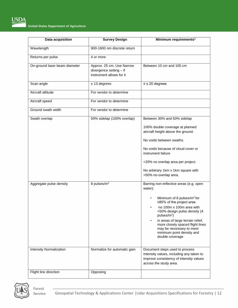
5. Data acquisition & Completeness:
The table below outlines the desired acquisition parameters. The data will be routinely evaluated
for completeness (as defined in Data Quality and assessed in the Data Quality Assurance
section).
Geospatial Technology & Applications Center |Lidar Acquisitions Specifications for Forestry | 12
Data acquisition Survey Design Minimum requirements1
Wavelength 900-1600 nm discrete return
Returns per pulse 4 or more
On-ground laser beam diameter Approx. 25 cm, Use Narrow
divergence setting – if
instrument allows for it
Between 10 cm and 100 cm
Scan angle ± 13 degrees ≤ ± 20 degrees
Aircraft altitude For vendor to determine
Aircraft speed For vendor to determine
Ground swath width For vendor to determine
Swath overlap 50% sidelap (100% overlap) Between 30% and 50% sidelap
100% double coverage at planned
aircraft height above the ground.
No voids between swaths.
No voids because of cloud cover or
instrument failure
<20% no overlap area per project.
No arbitrary 1km x 1km square with
>50% no-overlap area.
Aggregate pulse density 8 pulses/m2 Barring non-reflective areas (e.g. open
water):
• Minimum of 8 pulses/m2 for ≥85% of the project area
• no 100m x 100m area with <50% design pulse density (4 pulses/m2)
• in areas of large terrain relief, more closely spaced flight lines may be necessary to meet minimum point density and double coverage
Intensity Normalization Normalize for automatic gain Document steps used to process
intensity values, including any taken to
improve consistency of intensity values
across the study area.
Flight line direction Opposing
Geospatial Technology & Applications Center |Lidar Acquisitions Specifications for Forestry | 13
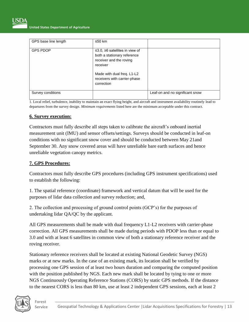
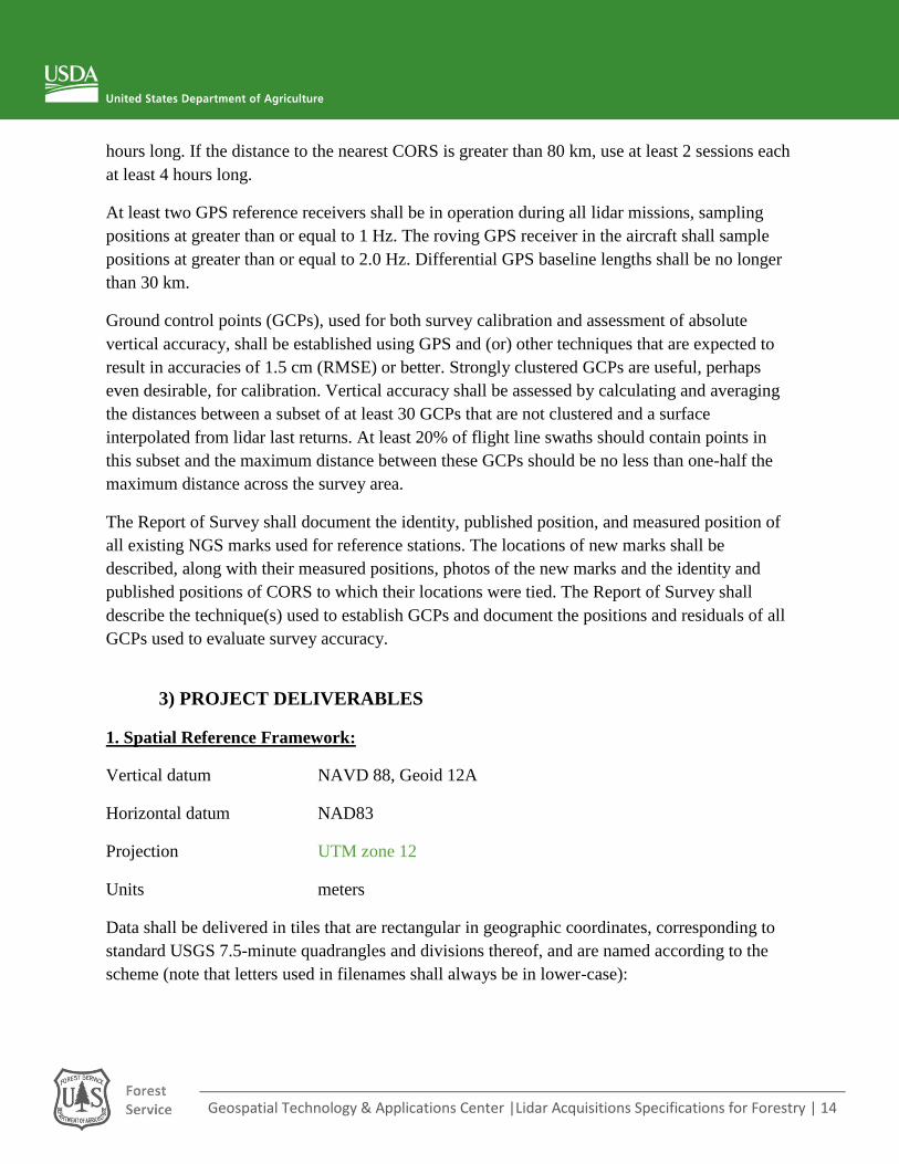
GPS base line length ≤50 km
GPS PDOP ≤3.0, ≥6 satellites in view of
both a stationary reference
receiver and the roving
receiver
Made with dual freq. L1-L2
receivers with carrier-phase
correction
Survey conditions Leaf-on and no significant snow
1. Local relief, turbulence, inability to maintain an exact flying height, and aircraft and instrument availability routinely lead to
departures from the survey design. Minimum requirements listed here are the minimum acceptable under this contract.
6. Survey execution:
Contractors must fully describe all steps taken to calibrate the aircraft’s onboard inertial
measurement unit (IMU) and sensor offsets/settings. Surveys should be conducted in leaf-on
conditions with no significant snow cover and should be conducted between May 21and
September 30. Any snow covered areas will have unreliable bare earth surfaces and hence
unreliable vegetation canopy metrics.
7. GPS Procedures:
Contractors must fully describe GPS procedures (including GPS instrument specifications) used
to establish the following:
1. The spatial reference (coordinate) framework and vertical datum that will be used for the
purposes of lidar data collection and survey reduction; and,
2. The collection and processing of ground control points (GCP’s) for the purposes of
undertaking lidar QA/QC by the applicant.
All GPS measurements shall be made with dual frequency L1-L2 receivers with carrier-phase
correction. All GPS measurements shall be made during periods with PDOP less than or equal to
3.0 and with at least 6 satellites in common view of both a stationary reference receiver and the
roving receiver.
Stationary reference receivers shall be located at existing National Geodetic Survey (NGS)
marks or at new marks. In the case of an existing mark, its location shall be verified by
processing one GPS session of at least two hours duration and comparing the computed position
with the position published by NGS. Each new mark shall be located by tying to one or more
NGS Continuously Operating Reference Stations (CORS) by static GPS methods. If the distance
to the nearest CORS is less than 80 km, use at least 2 independent GPS sessions, each at least 2
Geospatial Technology & Applications Center |Lidar Acquisitions Specifications for Forestry | 14
hours long. If the distance to the nearest CORS is greater than 80 km, use at least 2 sessions each
at least 4 hours long.
At least two GPS reference receivers shall be in operation during all lidar missions, sampling
positions at greater than or equal to 1 Hz. The roving GPS receiver in the aircraft shall sample
positions at greater than or equal to 2.0 Hz. Differential GPS baseline lengths shall be no longer
than 30 km.
Ground control points (GCPs), used for both survey calibration and assessment of absolute
vertical accuracy, shall be established using GPS and (or) other techniques that are expected to
result in accuracies of 1.5 cm (RMSE) or better. Strongly clustered GCPs are useful, perhaps
even desirable, for calibration. Vertical accuracy shall be assessed by calculating and averaging
the distances between a subset of at least 30 GCPs that are not clustered and a surface
interpolated from lidar last returns. At least 20% of flight line swaths should contain points in
this subset and the maximum distance between these GCPs should be no less than one-half the
maximum distance across the survey area.
The Report of Survey shall document the identity, published position, and measured position of
all existing NGS marks used for reference stations. The locations of new marks shall be
described, along with their measured positions, photos of the new marks and the identity and
published positions of CORS to which their locations were tied. The Report of Survey shall
describe the technique(s) used to establish GCPs and document the positions and residuals of all
GCPs used to evaluate survey accuracy.
3) PROJECT DELIVERABLES
1. Spatial Reference Framework:
Vertical datum NAVD 88, Geoid 12A
Horizontal datum NAD83
Projection UTM zone 12
Units meters
Data shall be delivered in tiles that are rectangular in geographic coordinates, corresponding to
standard USGS 7.5-minute quadrangles and divisions thereof, and are named according to the
scheme (note that letters used in filenames shall always be in lower-case):

Geospatial Technology & Applications Center |Lidar Acquisitions Specifications for Forestry | 15
AAOOORCQ (quarter-quadrangle, 3.75 minute by 3.75 minute region)
AAOOORCQNN (1/100th quadrangle, 0.75 minute by 0.75 minute region)
where AA is the integer north latitude of the SE corner of the 8 by 8 region that contains the
quadrangle, OOO is the integer west longitude of the SE corner of the 8 by 8 region, R is the
row, labeled from a to h, south to north, and C is the column, labeled from 1 to 8, east to west.
That is, in diagram A below of the 8 by 8 region with a southeast corner at 45N, longitude 118W,
the highlighted quadrangle is 45118d2.
Q is the quadrangle quadrant, which shall be numbered west-to-east, north-to-south, as is shown
in diagram B below. That is, the highlighted quarter-quadrangle tile in diagram B is 45118d22.
QNN identifies the 1/100th quadrangle, which shall be labeled by numbering the 25 divisions of
each quarter-quadrangle west-to-east, north-to-south, as shown in diagram C below. That is, the
highlighted tile in diagram C is 45118d2209.
Report: Deliverables the Contractor shall provide to the Authorized Purchaser include a Report
of Survey, Aircraft trajectories, .las format all-return point files, Ground (Bare-earth) DEM, Full-
feature (highest-hit) DEM, ground point list, intensity image, and formal metadata . The Report
of Survey shall be a digital text report that describes survey methods; results; Contractor’s
accuracy assessments, including internal reproducibility and absolute accuracy; file formats; file
naming schemes; tiling schemes.
Aircraft trajectories: (SBET files) shall be ASCII point files or ESRI shape files, with aircraft
position (easting, northing, elevation) and attitude (heading, pitch, roll) and GPS time recorded at
Geospatial Technology & Applications Center |Lidar Acquisitions Specifications for Forestry | 16
regular intervals of 1 second or less. May include additional attributes, such as temperature and
humidity or other relative information the contractor deems appropriate.
All-return point cloud: shall be .las v1.4 format files listing all valid returns; all fields
populated. For each return: GPS week and GPS second OR Posix time, easting, northing,
elevation, intensity, return #, return classification. May include additional attributes. No
duplicate entries. Time shall be reported to the nearest microsecond or better. Easting, northing,
and elevation shall be reported to nearest 0.01 meter (nearest 0.01 feet). Classification of returns
shall be as complete as is feasible and without avoidable return misclassification. 1/100th USGS
7.5-minute quadrangle (0.75 minute by 0.75 minute) tiles.
Bare-earth filtered point cloud: Shall be .las v1.4 file containing only returns identified as
ground returns.
Bare-earth surface model (DEM): Raster of ground surface, interpolated via triangulated
irregular network from identified ground points. Grids shall conform to the following
specifications: ESRI floating point grid, 1 m cell size, snapped to (0, 0), 1/4th USGS 7.5-minute
quadrangle (3.75 minute by 3.75 minute) tiles. The triangulated irregular networks from which
ground surface raster models are interpolated should not include break lines derived from other
data sources. Surface models shall have no tiling artifacts and no gaps at tile boundaries. Areas
outside survey boundary shall be coded as NoData.
First-return (highest-hit) surface model (DSM): Raster of first-return surface, cell heights are
highest first return within that cell, cells without first returns shall be coded as NoData. Shall
conform to the same file and grid formats as Bare-earth surface model (DEM). 1/4th USGS 7.5-
minute quadrangle (3.75 minute by 3.75 minute) tiles. Surface models shall have no tiling
artifacts and no gaps at tile boundaries. Areas outside survey boundary shall be coded as NoData.
Intensity image: Raster of 1st-return intensity. Vegetation analysis using the intensity image
requires that values be consistent. The Contractor must document how the intensity image is
calibrated or normalized to reduce inconsistencies that limit its utility for analysis. TIFF, 1 m
pixel size, 1/4th USGS 7.5-minute quadrangle (3.75 minute by 3.75 minute) tiles.
Surface models shall have no tiling artifacts and no gaps at tile boundaries. Areas outside survey
boundary shall be coded as NoData.
Supporting shapefiles:
1) A shapefile of all ground survey monument points established by the vendor for the
project.
2) Shapefiles of the tiling tessellation (polygon feature) for the bare earth models and the
lidar tiles.
Geospatial Technology & Applications Center |Lidar Acquisitions Specifications for Forestry | 17
The attribute name for each tile in the index shapefiles must match exactly the name
of its corresponding *.las or ArcGRID file. Letters used in names shall be lower-case.
3) Shapefiles with the tracking of the individual flight lines and flight line swaths (line and
polygon features, respectively).
Formal metadata: GIS-compatible data and files shall be explained with XML format metadata
that follows the Federal Geographic Data Committee's (FGDC) Content Standard for Digital
Geospatial Data. Metadata may be a single file that describes an entire survey or multiple files
each of which describes a constituent part (e.g., area A, area B, area C) of the survey. Metadata
should be completed for all deliverables, including point clouds, DEM, DSM and Intensity
images as well as shapefiles. Metadata shall include, but is not limited to, the following:
Under Identification Information
Description, Abstract
An abstract summarizing the datasets delivered. Include project area.
Include general tiling scheme (e.g., USGS 7.5 quarter quad). For each data layer,
describe
Data structure and attributes, including resolution and precision
Total number of files
Time Period
Date(s) of data capture (range of dates)
For these dates, use the Current Reference: ground condition.
Status
Statement regarding completeness status.
Spatial Domain, Bounding Coordinates and G-Polygon
Project survey area bounding coordinates in decimal degrees
Data Set Credit
Name and address of the Contractor.
Names of the agencies that contributed funds and participated in the acquisition of
the data. Other citation details for explanation of the data acquisition project. The
Geospatial Technology & Applications Center |Lidar Acquisitions Specifications for Forestry | 18
names of these agencies will be provided to the Contractor by the Authorized
Purchaser.
Under Data Quality
Process Step
Process Description for manufacturer, model, and serial number of lidar
instrument(s). May include separate specifications for scanning laser rangefinder,
inertial navigation system, and GPS unit Value(s) of instrument parameters during
survey, including
Nominal on-ground beam diameter pulse rate
Maximum number of returns recorded
Minimum separation between detected returns from a single
Pulse, expressed as a distance
Laser output power
Minimum return power required to produce a return
Beam wavelength
Frequency of GPS sampling
Frequency of IMU sampling
Nominal swath width
Nominal single-swath pulse density
Nominal aggregate pulse density
Identity and assumed coordinates of reference survey monument(s)
Nature of vertical control (e.g., RTK GPS or water surface + tidal
Observations)
Calibration procedures
Return classification procedures
Positional Accuracy
Geospatial Technology & Applications Center |Lidar Acquisitions Specifications for Forestry | 19
Vertical Accuracy Report. Accuracy may be specified as RMSE or 95%
confidence (indicate which). Vertical accuracy shall be reported for lidar
measurements and, optionally, for the derived ground (bare earth) surface model.
XY accuracy of lidar measurements may also be reported. Shall include one or
more of the following sections:
Accuracy as predicted by creator of survey
Accuracy as measured by creator of survey
Accuracy as verified by contracting agency or independent
3rd party.
The accuracy as verified by the contracting agency or independent 3rd
party will be provided to the Contractor by the Authorized Purchaser.
Under Spatial Data Organization Information
Indirect Spatial Reference
Tiling scheme (if any). (e.g. .las data is divided into 1/100th USGS 7.5” quad)
Under Spatial Reference Information
Horizontal Coordinate System Definition:
Geographic Coordinate System for the captured data
Projected Coordinate System for the delivered data
Horizontal Datum for the delivered data
Ellipsoid Name (identify both the ellipsoid and the geoid model used to translate
from ellipsoid to orthometric heights)
Vertical Coordinate System Definition
Datum Name
Vertical units
Geospatial Technology & Applications Center |Lidar Acquisitions Specifications for Forestry | 20
Under Entity and Attribute Information
Overview Description, Entity and Attribute Overview
Attribute descriptions if applicable (e.g. user bit field in .las format).
For all-return data, definition of return classification codes. Any other relevant
attribute information.
Under Distribution Information
Distributor
Distribution point of contact
The distribution point of contact will be provided to the Contractor by the
Authorized Purchaser.
Standard Order Process
Ordering Instructions - web location, if applicable
The ordering instructions will be provided to the Contractor by the Authorized
Purchaser.
Distribution Liability
Absence of intellectual property restrictions
The absence of intellectual property restrictions will be provided to the Contractor
by the Authorized Purchaser.
Under Metadata Reference Information
Metadata Contact
Details for author(s) of metadata. The details shall include the name of the
Contractors personnel, telephone number and email address.
Metadata Standard Name
“FGDC Content Standards for Digital Geospatial Metadata”
Metadata Standard Version
“FGDC-STD-001-1998” unless updated or otherwise substituted

Geospatial Technology & Applications Center |Lidar Acquisitions Specifications for Forestry | 21
Usability: Names of data files shall be composed of the tile name followed, in some cases, by a
suffix that denotes the data layer and (or) the file format. In some cases this name shall have
additional suffixes that denote an export file and (or) file compression.
For the quarter-quadrangle 45123a3 and constituent 1/100th-quadrangle tile
45123a301, these are the names of data files:
All-return point cloud
45123a301.las (.las file)
Ground (bare-earth) surface model
45123a3be (ESRI grid name)
45123a3be.e00 (ESRI export file)
First-return (highest-hit) surface model
45123a3hh (ESRI grid name)
45123a3hh.e00 (ESRI export file)
Ground point list
45123a3 (ESRI shapefile)
First-return (highest-hit) intensity image
45123a3hh.tif (TIFF image; with accompanying .tfw file)
Files shall have consistent formats.
Some of the QAQC processes are case-sensitive. So, for the processes to run properly, the file
name for each 1/100th quadrangle tile in the index shapefile must match exactly the name for its
corresponding *.las file. For the sake of consistency, all filenames should contain only lower-
case letters.
Contractor shall propose all details of file names and file formats that are not specified here.
Contractors proposed names and formats must be approved by Authorized Purchaser. GIS (ESRI
grids, shapefiles) shall have complete and correct associated projection files.
All files must be readable.

Geospatial Technology & Applications Center |Lidar Acquisitions Specifications for Forestry | 22
Failure of data to meet format specifications, files that have inconsistent internal formats or are
not readable, GIS data that have incomplete or incorrect associated projection files shall result in
reformatting and re-delivery.
Descriptive file list documenting all of the delivered files.
Deliverable media: USB 3.0 external hard drive
2. Delivery Schedule:
Contractor shall provide digital data to Authorized Purchaser on new portable hard drives at
Contractor’s expense. The final delivery shall be made no later than 60 Business Days from end
of data acquisition. The data acquisition timeline shall be mutually agreed upon by the
Authorized Purchaser and the Contractor. Authorized Purchaser will review and accept or reject
products within 30 Business Days of delivery. Following a thorough Quality Assurance (as
outlined in #4 Data Quality Assurance) review by Authorized Purchaser staff, data will be
accepted or rejected based on the data products meeting the Technical Specifications.
3. Data Quality:
Survey data shall meet or exceed requirements, described below, for within-swath
reproducibility, first-return swath-to-swath reproducibility, absolute accuracy, completeness, and
surface quality. Authorized Purchaser may reject data if it can demonstrate, to the satisfaction of
the Contractor or a qualified independent observer, that data do not meet Technical
Specifications. Rejection of data shall result in, at the discretion of Authorized Purchaser, rework
(including reacquisition if necessary), non-payment or re-negotiation of payment. At Authorized
Purchaser’s discretion, Authorized Purchaser and Contractor may negotiate partial non-payment
for partially unsatisfactory data (see Data Quality Assurance section). There shall be no charge
and no additional mobilization fee for any necessary re-acquisition.
Within-swath reproducibility—Single-swath data from planar surfaces shall show no
departures from planarity greater than 10 cm for project as a whole, and the average (RMSE)
departure from planarity within any 10m x 10m area shall be no greater than 5 cm.
First-return swath-to-swath reproducibility—Absent real changes in surface elevation
between successive measurements, the root mean square vertical error as estimated by the
internal reproducibility of a survey shall not exceed 15 cm. This value shall be established by
averaging of reproducibility determined from suitable near-planar areas across an entire survey
(50 mi2 minimum) area. Vertical errors may be greater on sloping surfaces; error will be
normalized by the following rule:
Geospatial Technology & Applications Center |Lidar Acquisitions Specifications for Forestry | 23
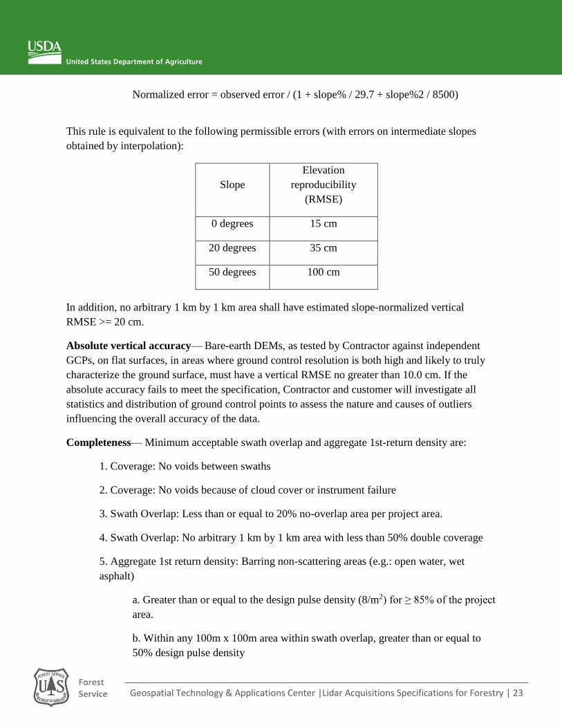
Normalized error = observed error / (1 + slope% / 29.7 + slope%2 / 8500)
This rule is equivalent to the following permissible errors (with errors on intermediate slopes
obtained by interpolation):
Slope
Elevation
reproducibility
(RMSE)
0 degrees 15 cm
20 degrees 35 cm
50 degrees 100 cm
In addition, no arbitrary 1 km by 1 km area shall have estimated slope-normalized vertical
RMSE >= 20 cm.
Absolute vertical accuracy— Bare-earth DEMs, as tested by Contractor against independent
GCPs, on flat surfaces, in areas where ground control resolution is both high and likely to truly
characterize the ground surface, must have a vertical RMSE no greater than 10.0 cm. If the
absolute accuracy fails to meet the specification, Contractor and customer will investigate all
statistics and distribution of ground control points to assess the nature and causes of outliers
influencing the overall accuracy of the data.
Completeness— Minimum acceptable swath overlap and aggregate 1st-return density are:
1. Coverage: No voids between swaths
2. Coverage: No voids because of cloud cover or instrument failure
3. Swath Overlap: Less than or equal to 20% no-overlap area per project area.
4. Swath Overlap: No arbitrary 1 km by 1 km area with less than 50% double coverage
5. Aggregate 1st return density: Barring non-scattering areas (e.g.: open water, wet
asphalt)
a. Greater than or equal to the design pulse density (8/m2) for ≥ 85% of the project
area.
b. Within any 100m x 100m area within swath overlap, greater than or equal to
50% design pulse density
Geospatial Technology & Applications Center |Lidar Acquisitions Specifications for Forestry | 24
Surface quality—there shall be no tile-boundary artifacts, no voids between DEM tiles, and no
avoidable misclassification of returns.
4. Data Quality Assurance
A thorough quality assurance assessment will be conducted by the Authorized Purchaser to
determine if the lidar data deliverables meet the specified Technical Specifications. The
procedure for assessing the quality of the data is outlined below.
1. Using FUSION software –
a. Use the catalog DOS command to assess pulses per sq. meter to determine if the
dataset meets the Technical Specifications, averaged over a 100m by 100m area.*
b. Use the catalog DOS command to flag tiles with potential elevation outliers.
c. Visual inspection – inspect 3D point cloud for all tiles for outliers, holes, gaps, etc.
d. Use catalog DOS command graphical output to visually inspect flight line overlap
(50% sidelap, 100% overlap) based on pulse density.
*1. Cells intersecting with the project area perimeter will not be assessed
2. As defined by NHD, cells containing polygon water features (e.g. StreamRiver and LakePond) will not
be assessed, however, cells containing line water features will be assessed in the Quality Assurance
assessment.
2. Using ArcGIS software –
a. Visual inspection of Bare-earth surface model (DEM) – looking for tile boundary
artifacts, gaps and holes.
b. Visual inspection of First-return (highest-hit) surface model (DSM) - looking for tile
boundary artifacts, gaps and holes
c. Visual inspection of flight line shapefile for opposing flight line pattern.
d. Review shapefiles for coverage and completeness and ensure they include correct
naming convention, metadata, and attributes.
If it is determined that the acquired lidar data is insufficient based on the Quality Assurance
assessment, the Contractor may be required to reprocess and/or re-fly problem areas to receive
full-payment or may be asked to re-negotiate a reduced price of the lidar deliverables. Each
Quality Assessment cell (100m by 100m) that does not meet the minimum Technical
Specifications of 4 pulses/square meter may cause a reduction in payment to the Contractor
equivalent to the cells percentage of the total area surveyed. If 3 percent or more of the Quality

Geospatial Technology & Applications Center |Lidar Acquisitions Specifications for Forestry | 25
Assessment cells do not meet the minimum Technical Specifications, then the Authorized
Purchaser has the right to re-negotiate a reduced price of the lidar deliverables.
SPECIAL PROVISIONS
3.1 Inspection: Contractor’s facilities and equipment shall be subject to inspection at any time by
a representative of the Authorized Purchaser.
3.2 Ownership of Data: All products, data, information, findings and documents prepared or
obtained under the terms of this Price Agreement shall become the exclusive property of the
Authorized Purchaser.
3.3 Access Agreements: The Contractor shall provide written notification to the Authorized
Purchaser on the number and locations of ground control points used in this Price Agreement.
The Contractor shall determine land ownership encompassing those locations and as required,
obtain site access permission. The Contractor shall notify landowners and coordinate with the
appropriate personnel prior to on-site or over-site activities. The Contractor shall be solely
responsible for the requisite filing of flight plans and obtaining appropriate permissions from the
FAA and other agencies as necessary.
3.4 Key Personnel: Contractor and the Government agree that each individual specified below is
an individual whose special qualifications and involvement in Contractor’s performance of
Services form part of the basis of agreement between the parties for this Contract and is an
individual through whom Contractor shall provide to Authorized Purchaser the expertise,
experience, judgment, and personal attention required to perform Services (“Key Person”). Each
of the following is a Key Person under this Price Agreement:
[List name, title, identify the specific services each Key Person is required to perform under
this Price Agreement.]
Neither Contractor nor any Key Person of Contractor shall delegate performance of Services any
Key Person is required to perform under this Price Agreement to others without first obtaining
Authorized Purchaser’s written consent. Further, Contractor shall not, without first obtaining
Authorized Purchaser's prior written consent, reassign or transfer any Key Person to other duties
or positions so that the Key Person is no longer available to provide Authorized Purchaser with
that Key Person’s expertise, experience, judgment, and personal attention. If Contractor requests
Authorized Purchaser to approve a re-assignment or transfer of a Key Person, Authorized
Purchaser shall have the right to interview, review the qualifications of, and approve or
disapprove the proposed replacement(s) for the Key Person. Any individual Authorized
Geospatial Technology & Applications Center |Lidar Acquisitions Specifications for Forestry | 26
Purchaser approves as a replacement for a Key Person is deemed a Key Person under this Price
Agreement.
PAYMENT
The contractor will submit all invoices using the IPP, Invoicing Processing Platform
(https://www.ipp.gov). The contractor will submit an invoice for 50% of the total fee after the data
acquisition is complete, and an invoice for the balance after deliverables are provided. The invoice
for the first 50% of the total fee shall be deemed valid and accepted unless the contractor is notified
within 14 calendar days after the receipt of invoice that the claim is rejected. The invoice for the
balance of the total fee shall be deemed valid and accepted unless the contractor is notified within
30 business days after the receipt of invoice that the claim is rejected. In that event, reasons for
such rejection shall be stated in a Notice of Rejection of Claim, which is sent using an expedient
service with confirmation of delivery.
EVALUATION FACTORS FOR AWARD
Award Determination
Award will be made to the offer whose proposal is considered to be the best value to the
Government, price and other factors considered. The Government intends to award this contract
without discussions.
The factors listed below under Price Proposal will account for 40% of the evaluation and the
factors listed under Technical Proposal will account for 60% of the evaluation.
Evaluation Factors
A. Price Proposal
Furnish price for all services and materials to complete the work described herein, including
appropriate taxes. No additional information will be necessary to determine the reasonableness of
price.
B. Technical Proposal
Past Performance – Including: timeliness of performance; quality of service, and business
relations. Provide examples of previous (within the past three years) large-area projects where
LiDAR data were acquired for forest structure applications.
Technical Approach, Current Project - Provide a description of the technical approach to be
implemented on this project.

Geospatial Technology & Applications Center |Lidar Acquisitions Specifications for Forestry | 27
Include contract information for previous purchasers to include: Name of Project, Location of
Project, Date of Project, Dollar Amount of Project, Project Manager Name and Contact
Information (email, phone number).
Points of Contact:
Four Forest Restoration Initiative
- Dick Fleishman, Acting 4FRI Team Leader, [email protected], 928-226-4687
(office)
- 4FRI Silviculturist, [TBD]
- Mark Nigrelli, GIS Specialist [email protected], 928-226-4688 (office)
Forest Service Southwestern Regional Office:
- Tom Mellin, Remote Sensing Unit Leader and Project Lead, [email protected], 505-
842-3845 (office), 505-301-8167 (cell)
- Pete Joria, Remote Sensing Analyst, [email protected], 505-842-3821 (office)
- Carol Boyd, Deputy Director Forest Management, [email protected], 505-842-3240
(office)
Apache-Sitgreaves National Forest
- Mark Empey, Aviation Officer, [email protected], 928-333-6315 (office), 928-240-
0978 (cell)
Contracting Officer
- Rufus Cole, Contracting Officer, [email protected], 505-842-3342 (office)
Recommended