11
Linear Actuator with ToothedBelt and Integrated Guide
– with Roller Guide– with Recirculating Ball Bearing Guide
Series OSP-E..BHD
Contents
Description Page
Overview 11-14
Version with Roller Guide
Technical Data 15-17
Dimensions 18, 23
Version with Recirculating Ball Bearing Guide
Technical Data 19-21
Dimensions 22, 23
88940 ORIG OSP-E_P1-46 1/21/05, 3:10 PM11
12
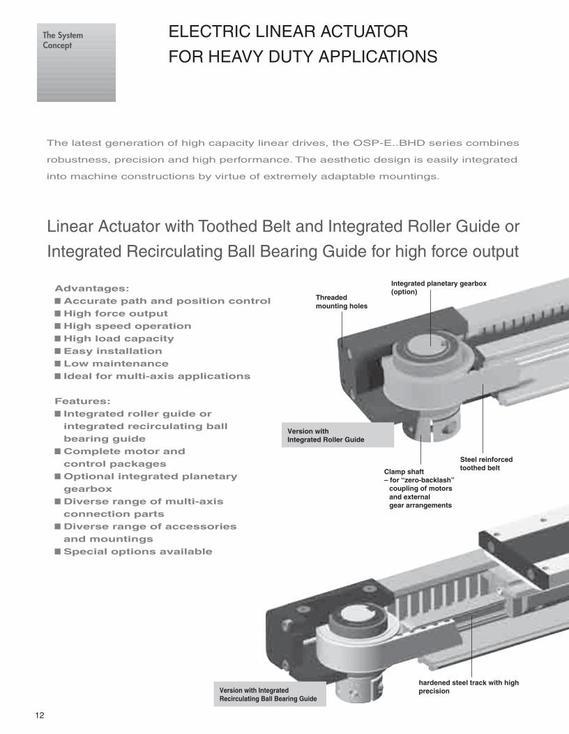
ELECTRIC LINEAR ACTUATOR
FOR HEAVY DUTY APPLICATIONS
The latest generation of high capacity linear drives, the OSP-E..BHD series combines
robustness, precision and high performance. The aesthetic design is easily integrated
into machine constructions by virtue of extremely adaptable mountings.
Linear Actuator with Toothed Belt and Integrated Roller Guide or
Integrated Recirculating Ball Bearing Guide for high force output
Advantages:
■ Accurate path and position control
■ High force output
■ High speed operation
■ High load capacity
■ Easy installation
■ Low maintenance
■ Ideal for multi-axis applications
Features:
■ Integrated roller guide or
integrated recirculating ball
bearing guide
■ Complete motor and
control packages
■ Optional integrated planetary
gearbox
■ Diverse range of multi-axis
connection parts
■ Diverse range of accessories
and mountings
■ Special options available
Version withIntegrated Roller Guide
Version with IntegratedRecirculating Ball Bearing Guide
hardened steel track with highprecision
Threadedmounting holes
Integrated planetary gearbox(option)
Clamp shaft– for “zero-backlash”
coupling of motorsand externalgear arrangements
Steel reinforcedtoothed belt
The SystemConcept
88940 ORIG OSP-E_P1-46 1/21/05, 3:10 PM12

13
OPTIONHollow shaft with keyway
Version with IntegratedRoller guide
Version with IntegratedRecirculating Ball BearingGuide
Steel runner block withintegrated scraper system andgrease nipples
Stainless steel sealing band
Threadedmounting holescompatible withProline series
Carriage
Optional Integrated
PLANETARY GEARBOX
• Highly compact and rigidsolution fully integrated in thedrive end housing
• Purpose designed for the BHDseries
• Available with three standardratlos (3, 5 and 10)
• Very low backlash• A wide range of available motor
flanges
BI-PARTING versionfor perfectly synchronisedbi-parting movements
MULTI-AXISA wide range of adapter platesand intermediate drive shaftssimplify engineering andinstallation
The dovetailed mounting rails ofthe new linear actuator expandits function into that of a univer-sal system carrier.Modular system components aresimply clamped on.
Permanent magnetfor position sensing
Slotted profile withdovetail grooves
Rollers on needle bearingsfor smooth operation up to10 m/s
Guide rail with precisionground and calibratedbearing tracks
88940 ORIG OSP-E_P1-46 1/21/05, 3:10 PM13

14
Accessories
MID-SECTION SUPPORT
Page 41For supporting long actuators ormounting the actuator on dovetailgrooves.
MAGNETIC SWITCHESSERIES RS AND ES
Page 130For electrical sensing of end of strokeand intermediate carrier positions.Schlittens.
MOTOR MOUNTINGS
Page 44For linear drive with clamp shaft
Page 25
For connection of linear drives inmulti-axis systems. Carrier to carrieror carrier to profile and connectingshaft for parallel drive arrangementsare available.
STANDARD VERSIONSOSP-E..BHDVersion with Roller GuidePage 15Version with Recirculating BallBearing GuidePage 19
Standard carrier with integratedroller guide. Dovetail profile formounting of accessories andthe actuator itself.
BASIC ACTUATOROPTIONS
BI-PARTING VERSIONPage 18For perfectly synchronised bi-partingmovements.
DRIVE SHAFT OPTIONSACTUATING DIRECTIONPage 144Important in parallel operations, e.g.with intermediate drive shaft
OPTIONS AND ACCESSORIES
The
rig
ht to
intr
oduc
e te
chni
cal
mod
ifica
tions
is r
eser
ved
SERIES OSP-E, BELT DRIVES WITH INTEGRATED GUIDE
(Standard)
INTEGRATED PLANETARY GEARBOX
Page 23For required torque and speedreduction
CLAMP SHAFT WITHCONNECTION SHAFTFor connection to connecting shaft(Page 38)
HOLLOW SHAFT WITH KEYWAYFor close coupling of motors and
external gears
ACCESSORIES
END CAP MOUNTINGPage 40For mounting the drives on theend cap
(Standard –Bi-PartingVersion)
88940 ORIG OSP-E_P1-46 1/21/05, 3:11 PM14

15
Characteristics
Characteristics Symbol Unit Description
General Futures
Type Belt-Driven Linear Actuator withintegrated roller guide
Series OSP-E..BHD / OSP-E..BHD-BP
Mounting See drawings
Ambient ϑmin
°C -30Temperature range ϑ
max°C +80
Weight (mass) kg See table
Installation In any position
Slotted profile Extruded anodized aluminium
Toothed belt Steel-corded polyurethane
Belt wheels Aluminium
Rails Aluminium
Tracks High alloy spring steel
Roller casettes Roller bearing steel in aluminium casing
Sealing band Hardened stainless steel
Screws, nuts Zinc plated steel
Mountings Zinc plated steel and aluminium
Encapsulation class IP 54
Linear Actuatorwith ToothedBeltand IntegratedRoller Guide
Series OSP-E..BHDSize 25, 32, 50
Installation Instructions
Use the threaded holes in the end capfor mounting the linear actuator.Check if mid-section supports areneeded using the maximum allowableunsupported length graph on page 17.At least one end cap must be securedto prevent axial sliding when mid-section support is used.
Commissioning
The products in this data sheet shouldnot be operated until the machine/application in which they are used haspassed necessary inspection.
Standard Versions:• Standard carrier with integrated
roller guide• Dovetail profile for mounting of
accessories and the actuator itself• Clamp shaft
Special Versions:• Bi-parting version for synchronised
movements (OSP-E..BHD -BP).• Integrated planetary gearbox.• Drive shaft / Actuating direction• Clamp shaft with connection shaft
(for use in Mutli-Axis systems withconnecting shaft)
• Hollow shaft with keyway
ORIGASYSTEM
PLUS
OSP
Mat
eria
l
The
rig
ht to
intr
oduc
e te
chni
cal
mod
ifica
tions
is r
eser
ved
Maintenance
All moving parts are lifetimelubricated. We recommend a check ofthe linear actuator after an operationtime of 12 months of operation or3000 km, depending on the type ofapplication. Please see separateinstructions.
Weight (mass) kg and Inertia
Series Weight (mass)|kg] Inertia [x 10-6/kgm2]At stroke 0 m Add per metre stroke Moving mass At stroke 0 m Add per metre
OSP-E25BHD 3.8 4.3 1.0 984 197
OSP-E32BHD 7.7 6.7 1.9 3498 438
OSP-E50BHD 22.6 15.2 4.7 19690 1489
OSP-E25BHD-BP 5.7 4.3 2.0 1805 197
OSP-E32BHD-BP 11.3 6.7 3.8 6358 438
OSP-E50BHD-BP 31.7 15.2 9.4 34274 1489
88940 ORIG OSP-E_P1-46 1/21/05, 3:11 PM15
16
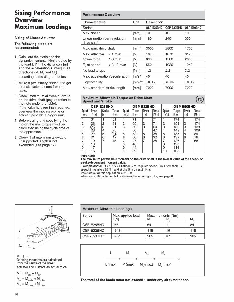
Sizing PerformanceOverviewMaximum Loadings
Sizing of Linear Actuator
The following steps arerecommended:
1. Calculate the static and thedynamic moments [Nm] created bythe load L [N], the distance r [m]and the acceleration a [m/s2] in alldirections (M, Ms and Mv)according to the diagram below.
2. Make a preliminary choice and getthe calculation factors from thetable.
3. Check maximum allowable torqueon the drive shaft (pay attention tothe note under the table).
If the value is lower than required,overview the moving profile orselect if possible a bigger unit.
4. Before sizing and specifying themotor, the rms torque must becalculated using the cycle time ofthe application.
5. Check that maximum allowableunsupported length is notexceeded (see page 17).
Performance Overview
Characteristics Unit Description
Series OSP-E25BHD OSP-E32BHD OSP-E50BHD
Max. speed [m/s] 10 10 10
Linear motion per revolution, [mm] 180 240 350drive shaft
Max. rpm. drive shaft [min-1] 3000 2500 1700
Max. effective < 1 m/s: [N] 1070 1870 3120action force 1-3 m/s: [N] 890 1560 2660
FA at speed > 3-10 m/s: [N] 550 1030 1940
No-load torque [Nm] 1.2 2.2 3.2
Max. acceleration/deceleration [m/s2] 40 40 40
Repeatability [mm/m] ±0.05 ±0.05 ±0.05
Max. standard stroke length [mm] 7000 7000 7000
OSP-E25BHD OSP-E32BHD OSP-E50BHDSpeed Torque Stroke Torque Speed Torque Stroke Torque Speed Torque Stroke Torque[m/s] [Nm] [m] [Nm] [m/s] [Nm] [m] [Nm] [m/s] [Nm] [m] [Nm]1 31 1 31 1 71 1 71 1 174 1 1742 28 2 31 2 65 2 71 2 159 2 1743 25 3 31 3 59 3 60 3 153 3 1384 23 4 25 4 56 4 47 4 143 4 1085 22 5 21 5 52 5 38 5 135 5 896 21 6 17 6 50 6 32 6 132 6 767 19 7 15 7 47 7 28 7 126 7 668 18 8 46 8 1209 17 9 44 9 11610 16 10 39 10 108
Important:The maximum permissible moment on the drive shaft is the lowest value of the speed- orstroke-dependent moment value.Example above: OSP-E25BHD-stroke 5 m, required speed 3 m/s from table T2;speed 3 m/s gives 25 Nm and stroke 5 m gives 21 Nm.Max. torque for this application is 21 Nm.When sizing Bi-parting units the stroke is the ordering stroke, see page 8.
Maximum Allowable Torque on Drive ShaftSpeed and Stroke
M = F · rBending moments are calculatedfrom the centre of the linearactuator and F indicates actual force
M = Mstat
+ Mdyn
Ms = Ms, stat + Ms, dyn
Mv
= Mv, stat
+ M
v, dyn
L
M Ms
Mv
r
r
FA
T2
L M Ms
Mv
–––––––– + –––––––– + –––––––– + –––––––––– ≤1
L (max) M
(max) M
s (max) M
v (max)
Series Max. applied load Max. moments [Nm]L[N] M M
sM
v
OSP-E25BHD 986 64 11 84
OSP-E32BHD 1348 115 19 115
OSP-E50BHD 3704 365 87 365
Maximum Allowable Loadings
The total of the loads must not exceed 1 under any circumstances.
88940 ORIG OSP-E_P1-46 1/21/05, 3:11 PM16

17
��
���
����
�����
� ��� ��� ��� ��� ��� ��� ��� ���
���
��
��
��
�
�
�
�
k
L
k
L
k
Maximum Allowable Unsupported Length – Placing of Mid-Section Support Maximum AllowableUnsupported Length
Stroke Length
Stroke Length
The stroke lengths of the linearactuators are available in multiples of10 mm up to 7000 mm
Other stroke lengths are available onrequest.
The end of stroke must not be usedas a mechanical stop.Allow an additional safety clear-ance at both ends equivalent to thelinear movement of one revolutionof the drive shaft, but at least100 mm.
The use of an AC motor withfrequency converter normallyrequires a larger clearance thanthat required for servo systems.
For advice, please contact yourlocal HOERBIGER-ORIGA technicalsupport department.
k = Max. allowable distance between mountings/mid-section support fora given load L
When loadings are below or up to the curve in the graph below the deflectionwill be max. 0.01 % of distance k
k
k
L
k
L L
L
Load
Max. distance
1 = BHD-25lx2 = BHD-32lx4 = BHD-50lx3 = BHD-25ly5 = BHD-32ly6 = BHD-50ly
* For Bi-parting version the max. load (L) is the total load of both carriers L = L
carrier 1 + L
carrier 2
lX
lZ
ly
lX
lZ
ly
88940 ORIG OSP-E_P1-46 1/21/05, 3:11 PM17

18
� �
� �
��
�
���
���
��
��
�
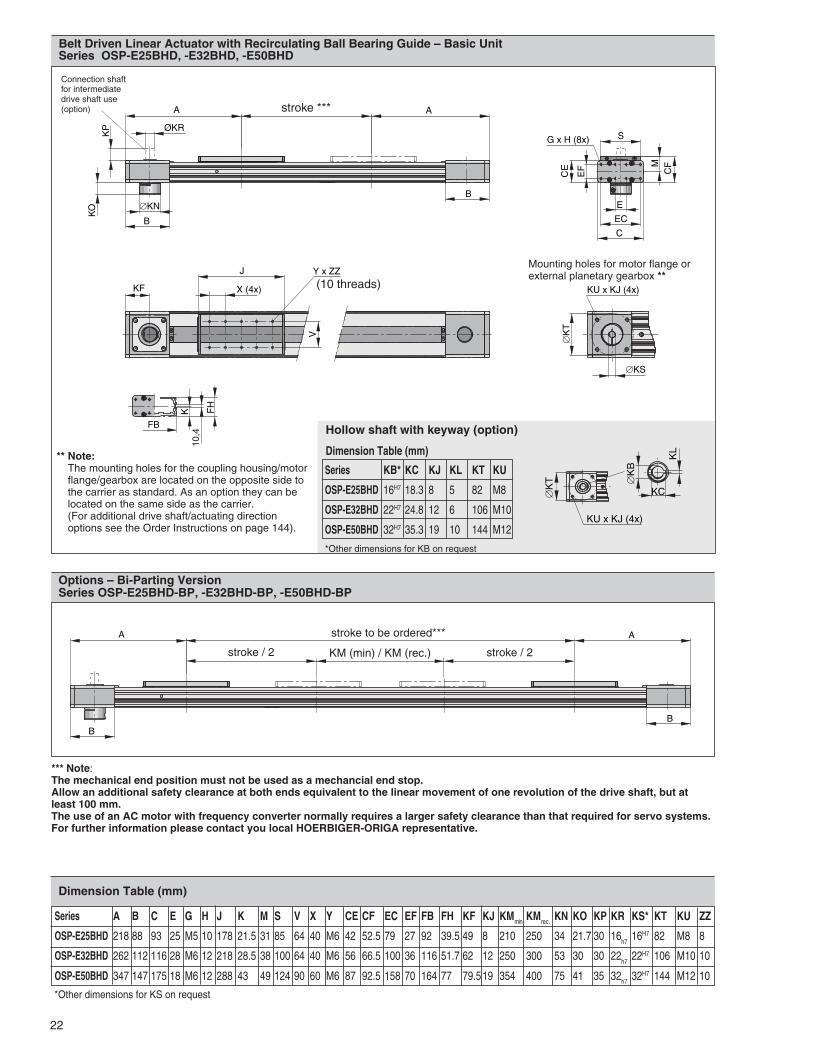
*** Note:The mechanical end position must not be used as a mechancial end stop.Allow an additional safety clearance at both ends equivalent to the linear movement of one revolution of the drive shaft, but atleast 100 mm.The use of an AC motor with frequency converter normally requires a larger safety clearance than that required for servo systems.For further information please contact you local HOERBIGER-ORIGA representative.
Options – Bi-Parting VersionSeries OSP-E25BHD-BP, -E32BHD-BP, -E50BHD-BP
Belt Driven Linear Actuator with Roller Guide – Basic UnitSeries OSP-E25BHD, -E32BHD, -E50BHD
stroke to be ordered***
KM (min) / KM (rec.)stroke / 2 stroke / 2
** Note:The mounting holes for the coupling housing/motorflange/gearbox are located on the opposite side tothe carrier as standard. As an option they can belocated on the same side as the carrier.(For additional drive shaft/actuating directionoptions see the Order Instructions on page 144).
stroke ***
Mounting holes for motor flange orexternal planetary gearbox **
Connection shaftfor intermediatedrive shaft use(option)
Hollow shaft with keyway (option)
*Other dimensions for KB on request
Serie KB* KC KJ KL KT KU
OSP-E25BHD 16H7 18.3 8 5 82 M8
OSP-E32BHD 22H7 24.8 12 6 106 M10
OSP-E50BHD 32H7 35.3 19 10 144 M12
Dimension Table (mm)
������
������ �
�
∅�
�
�����������
�
∅�
���
∅�
�
∅�
�����������
�
��
����
��
��
���������
Dimension Table (mm)
(10 threads)
Series A B C E G H J K M S V X Y CE CF EC EF FB FH KF KJ KMmin KMrec. KN KO KP KR KS* KT KU ZZ
OSP-E25BHD 218 88 93 25 M5 10 178 21.5 31 85 64 40 M6 42 52.5 79 27 92 39.5 49 8 210 250 34 21.7 30 16h7 16H7 82 M8 8
OSP-E32BHD 262 112 116 28 M6 12 218 28.5 38 100 64 40 M6 56 66.5 100 36 116 51.7 62 12 250 300 53 30 30 22h7 22H7 106 M10 10
OSP-E50BHD 347 147 175 18 M6 12 263 43 49 124 90 60 M6 87 92.5 158 70 164 77 79.5 19 295 350 75 41 35 32h7 32H7 144 M12 10
*Other dimensions for KS on request
88940 ORIG OSP-E_P1-46 1/21/05, 3:11 PM18

19
Characteristics
Characteristics Symbol Unit Description
General Features
Type Belt-Driven Linear Actuator withintegrated Recirculating Ball Bearing Guide
Series OSP-E..BHD / OSP-E..BHD-BP
Mounting See drawings
Ambient ϑmin
°C -30Temperature range ϑ
max°C +80
Weight (mass) kg See table
Installation In any position
Slotted profile Extruded anodized aluminium
Toothed belt Steel-corded polyurethane
Belt wheels Aluminium
Rail Steel
Track hardened steel track with highprecision, accuracy class H
Runner block Steel runner block with integratedscraper system, grease nipples, pre-loaded 0.02xC, accuracy H (N for Ø25)
Sealing band Hardened stainless steel
Screws, nuts Zinc plated steel
Mountings Zinc plated steel and aluminium
Encapsulation class IP 54
Linear Actuatorwith ToothedBeltand IntegratedRecirculating BallBearing Guide
Series OSP-E..BHDSize 25, 32, 50
Installation Instructions
Use the threaded holes in the end capfor mounting the linear actuator.Check if mid-section supports areneeded using the maximum allowableunsupported length graph on page 21.At least one end cap must be securedto prevent axial sliding when mid-section support is used.
Standard Versions:• Standard carrier with integrated
recirculating ball bearing guide• Dovetail profile for mounting of
accessories and the actuator itself• Clamp shaft
Special Versions:• Bi-parting version for synchronised
movements (OSP-E..BHD -BP).• Integrated planetary gearbox.• Drive shaft / Actuating direction• Clamp shaft with connection shaft
(for use in Multi-Axis systems withconnecting shaft)
• Hollow shaft with keyway
���������
�� �
���
Mat
eria
l
Weight (mass) kg and Inertia
Series Weight (mass) [kg] Inertia [x 10-6 kgm2]At stroke 0 m Add per metre stroke Moving mass At stroke 0 m Add per metre stroke Add per kg Mass
OSP-E25BHD 4.3 3.7 1.5 1229 227 821
OSP-E32BHD 8.8 7.8 2.6 3945 496 1459
OSP-E50BHD 26 17 7.8 25678 1738 3103
OSP-E25BHD-BP 6.7 3.7 2.8 2353 227 821
OSP-E32BHD-BP 13.5 7.8 5.2 7733 496 1459
OSP-E50BHD-BP 40 17 15 49180 1738 3103
Maintenance
We recommend a check of the linearactuator after an operation time of12 months of operation or 3000 km,depending on the type of application.Please see separate instructions.
Commissioning
The products in this data sheet shouldnot be operated until the machine/application in which they are used haspassed necessary inspection.
88940 ORIG OSP-E_P1-46 2/2/05, 9:33 AM19

20
Sizing PerformanceOverviewMaximum Loadings
Sizing of Linear Actuator
The following steps arerecommended:
1. Calculate the static and thedynamic moments [Nm] created bythe load L [N], the distance r [m]and the acceleration a [m/s2] in alldirections (M, Ms and Mv)according to the diagram below.
2. Make a preliminary choice and getthe calculation factors from thetable.
3. Check maximum allowable torqueon the drive shaft (pay attention tothe note under the table).
If the value is lower than required,overview the moving profile orselect if possible a bigger unit.
4. Before sizing and specifying themotor, the rms torque must becalculated using the cycle time ofthe application.
5. Check that maximum allowableunsupported length is notexceeded (see page 21).
Performance Overview
Characteristics Unit Description
Series OSP-E25BHD OSP-E32BHD OSP-E50BHD
Max. speed [m/s] 51) 51) 51)
Linear motion per revolution, [mm] 180 240 350drive shaft
Max. rpm. drive shaft [min-1] 1700 1250 860
Max. effektive < 1 m/s: [N] 1070 1870 3120
action force FA
1-3 m/s: [N] 890 1560 2660
at speed > 3 m/s: [N] 550 1030 1940
No-load torque [Nm] 1.2 2.2 3.2
Max. acceleration/deceleration [m/s2] 50 50 50
Repeatability [mm/m] ±0.05 ±0.05 ±0.05
Max. standard stroke length [mm] 57002) 56002) 55002)
1) up to 10 m/s on request2) longer strokes on request
OSP-E25BHD OSP-E32BHD OSP-E50BHDSpeed Torque Stroke Torque Speed Torque Stroke Torque Speed Torque Stroke Torque[m/s] [Nm] [m] [Nm] [m/s] [Nm] [m] [Nm] [m/s] [Nm] [m] [Nm]
1 31 1 31 1 71 1 71 1 174 1 1742 28 2 31 2 65 2 71 2 159 2 1743 25 3 31 3 59 3 60 3 153 3 1384 23 4 25 4 56 4 47 4 143 4 1085 22 5 21 5 52 5 38 5 135 5 89
Important:The maximum permissible moment on the drive shaft is the lowest value of the speed- orstroke-dependent moment value.Example above: OSP-E25BHD-stroke 5 m, required speed 3 m/s from table T2;speed 3 m/s gives 25 Nm and stroke 5 m gives 21 Nm.Max. torque for this application is 21 Nm.When sizing Bi-parting units the stroke is the ordering stroke, see page 22.
Maximum Allowable Torque on Drive ShaftSpeed and Stroke
M = F · rBending moments are calculatedfrom the centre of the linearactuator and F indicates actual force
M = Mstat + Mdyn
Ms
= Ms, stat
+ M
s, dyn
Mv
= Mv, stat
+ M
v, dyn
T2
Series Max. applied load Max. moments [Nm]L1[N] L2[N] M Ms Mv
OSP-E25BHD 3000 2000 500 50 500
OSP-E32BHD 10000 5000 1000 120 1400
OSP-E50BHD 15000 12000 1800 180 2500
If multiple forces and moments act upon the actuator simultaneously,the following equation applies.
Maximum Allowable Loadings
The total of the loads must not exceed 1 under any circumstances.
L1 L2 M Ms
Mv
+ + + + ≤1
L1 (max) L2 (max) M (max) Ms (max) Mv (max)
��
� ��
��
�
�
��
��
88940 ORIG OSP-E_P1-46 1/21/05, 3:12 PM20

21
��
����
������
� ��� ��� ��� ��� ��� ��� ��� ���
�����
���
� � �
� �
�
��
k
L
k
L
k
Maximum Allowable Unsupported Length – Placing of Mid-Section Support Maximum AllowableUnsupported LengthStroke LengthStroke Length
The stroke lengths of the linearactuators are available in multiples of10 mm up to 5700 mm
Other stroke lengths are available onrequest.
The end of stroke must not be usedas a mechanical stop.Allow an additional safety clear-ance at both ends equivalent to thelinear movement of one revolutionof the drive shaft, but at least100 mm.
The use of an AC motor withfrequency converter normallyrequires a larger clearance thanthat required for servo systems.
For advice, please contact yourlocal HOERBIGER-ORIGA technicalsupport department.
k = Max. allowable distance between mountings/mid-section support fora given load L
When loadings are below or up to the curve in the graph below the deflectionwill be max. 0.01 % of distance k
k
k
L
k
L L
L
LoadL [N]
Max. distance
1 = BHD-25lx2 = BHD-32lx4 = BHD-50lx3 = BHD-25ly5 = BHD-32ly6 = BHD-50ly
* For Bi-parting version the max. load (L) is the total load of both carriers L = L
carrier 1 + L
carrier 2
lX
lZly
lX
lZ
ly
k [m]
88940 ORIG OSP-E_P1-46 1/21/05, 3:12 PM21
22
� �
��
� �
���
��
�
���
��
�
��
�
����� ��!
��"
��
�
# ��!
$�%%
&
�
'(
(� '�
(
('
'
")�* +�!
*** Note:The mechanical end position must not be used as a mechancial end stop.Allow an additional safety clearance at both ends equivalent to the linear movement of one revolution of the drive shaft, but atleast 100 mm.The use of an AC motor with frequency converter normally requires a larger safety clearance than that required for servo systems.For further information please contact you local HOERBIGER-ORIGA representative.
Options – Bi-Parting VersionSeries OSP-E25BHD-BP, -E32BHD-BP, -E50BHD-BP
Belt Driven Linear Actuator with Recirculating Ball Bearing Guide – Basic UnitSeries OSP-E25BHD, -E32BHD, -E50BHD
stroke to be ordered***
KM (min) / KM (rec.)stroke / 2 stroke / 2
** Note:The mounting holes for the coupling housing/motorflange/gearbox are located on the opposite side tothe carrier as standard. As an option they can belocated on the same side as the carrier.(For additional drive shaft/actuating directionoptions see the Order Instructions on page 144).
stroke ***
Mounting holes for motor flange orexternal planetary gearbox **
Connection shaftfor intermediatedrive shaft use(option)
Hollow shaft with keyway (option)
*Other dimensions for KB on request
Series KB* KC KJ KL KT KU
OSP-E25BHD 16H7 18.3 8 5 82 M8
OSP-E32BHD 22H7 24.8 12 6 106 M10
OSP-E50BHD 32H7 35.3 19 10 144 M12
Dimension Table (mm)
Series A B C E G H J K M S V X Y CE CF EC EF FB FH KF KJ KMmin KMrec. KN KO KP KR KS* KT KU ZZ
OSP-E25BHD 218 88 93 25 M5 10 178 21.5 31 85 64 40 M6 42 52.5 79 27 92 39.5 49 8 210 250 34 21.7 30 16h7
16H7 82 M8 8
OSP-E32BHD 262 112 116 28 M6 12 218 28.5 38 100 64 40 M6 56 66.5 100 36 116 51.7 62 12 250 300 53 30 30 22h7
22H7 106 M10 10
OSP-E50BHD 347 147 175 18 M6 12 288 43 49 124 90 60 M6 87 92.5 158 70 164 77 79.519 354 400 75 41 35 32h7 32H7 144 M12 10
*Other dimensions for KS on request
Dimension Table (mm)
��
�
����� ��!
�'
��
��
�
(10 threads)
���
��
�*
��
88940 ORIG OSP-E_P1-46 1/21/05, 3:12 PM22
23
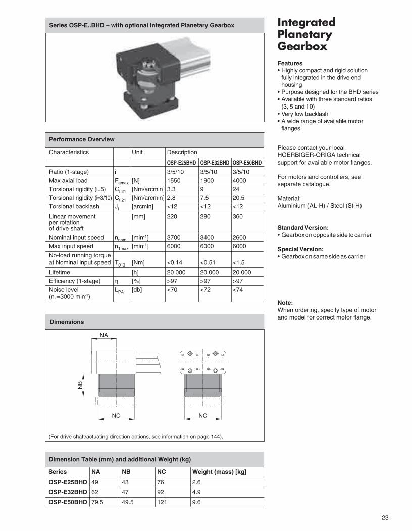
IntegratedPlanetaryGearboxFeatures• Highly compact and rigid solution
fully integrated in the drive endhousing
• Purpose designed for the BHD series• Available with three standard ratios
(3, 5 and 10)• Very low backlash• A wide range of available motor
flanges
Please contact your localHOERBIGER-ORIGA technicalsupport for available motor flanges.
For motors and controllers, seeseparate catalogue.
Material:Aluminium (AL-H) / Steel (St-H)
Standard Version:• Gearbox on opposite side to carrier
Special Version:• Gearbox on same side as carrier
Note:When ordering, specify type of motorand model for correct motor flange.
Series OSP-E..BHD – with optional Integrated Planetary Gearbox
Series NA NB NC Weight (mass) [kg]
OSP-E25BHD 49 43 76 2.6
OSP-E32BHD 62 47 92 4.9
OSP-E50BHD 79.5 49.5 121 9.6
Dimension Table (mm) and additional Weight (kg)
Dimensions
(For drive shaft/actuating direction options, see information on page 144).
NA
NC NC
NB
Performance Overview
Characteristics Unit Description
OSP-E25BHD OSP-E32BHD OSP-E50BHD
Ratio (1-stage) i 3/5/10 3/5/10 3/5/10Max axial load Famax [N] 1550 1900 4000Torsional rigidity (i=5) Ct.21 [Nm/arcmin] 3.3 9 24Torsional rigidity (i=3/10) Ct.21 [Nm/arcmin] 2.8 7.5 20.5Torsional backlash Jt [arcmin] <12 <12 <12
Linear movement [mm] 220 280 360per rotationof drive shaft
Nominal input speed nnom [min-1] 3700 3400 2600Max input speed n1max [min-1] 6000 6000 6000
No-load running torqueat Nominal input speed T012 [Nm] <0.14 <0.51 <1.5
Lifetime [h] 20 000 20 000 20 000Efficiency (1-stage) η [%] >97 >97 >97Noise level LPA [db] <70 <72 <74(n1=3000 min-1)
88940 ORIG OSP-E_P1-46 1/21/05, 3:12 PM23

24
88940 ORIG OSP-E_P1-46 1/21/05, 3:12 PM24
Recommended