
Z1DRIVE
TECHNOLOGY
Electric Motors Three - phase Electric Motors Single - phase Electric Motors Motors of Welded Construction DC - Electric Motors EEx - Electric Motors Special Electric Motors Generators and Converters
Gearunits and Gearmotors Helical Gearmotors Helical Shaft Mounted Gearmotors Worm Gearmotors Variable Speed Drives Special Gear Units
Electronics, Regulation and Automatic Control Power Electronics
- semi - conductive rpm regulators for DC motors - semi - conductive rpm regulators for AC motors - devices for smooth motor starting - other special - purpose power electronic devices
Process Electronics and Automation - electronic relays - freely programmable devices - special - purpose microprocessor control devices
Low - Voltage and Medium Voltage Control Units and Devices - All - purpose low voltage control - distribution cabinets - special - purpose low voltage control - distribution cabinets - automatic starters - medium - voltage motorstart cubicles
Other Programmes Pumps and Pump Systems Household Appliances Overhaul and Service Process Equipment Irrigation Equipment El. Power Units Engineering
Z2CONTENTS
GEARUNITS AND GEARMOTORS
................................................................................
Page Z3
HELICAL AND HELICAL SHAFT Introduction.................................................................... Z4 MOUNTED GEARMOTORS Technical Execution....................................................... Z4 Power, Torque and Speed ...................... .................... Z4 Efficiency ..................................................................... Z4 Gearunit Weight ...............................................…….… Z4, Z12 Modular System .......... ................................................ Z5 Designation ................................................................... Z5 Enquiru and Order Data Sheet...................................... Z6 Drive Selection ................. ........................................... Z7-Z9 Lubrication ................................................................... Z10 Mounting Position......................................................... Z11 General Notes Appertaining to the Dimension Sheets... Z13 Instructions for Installation, operation & Maintenance... Z14 Delivery and Storage.................................................... Z14 Installation......... .......................................................... Z14 Assembly and Disassembly........................................... Z14 Vibrations ..................................................................... Z14 Starting ......................................................................... Z15 Maintenance ................................................................ Z15 Spare Parts ................................................................ Z15
HELICAL GEARMOTORS Selection Tables ........................................................... Z17-Z23 Dimensions Sheets....................................................... Z30-Z37
HELICAL GEAR UNITS Selection Tables .......................................................... Z24-Z26 Dimensions Sheets....................................................... Z38-Z39
DOUBLE HELICAL GEARMOTORS Description ................................................................... Z27 Selection ...................................................................... Z27-Z29
HELICAL SHAFT MOUNTED Selection Tables .......................................................... Z41-Z42 GEARMOTORS Dimensions Sheets ...................................................... Z45-Z46
HELICAL SHAFT MOUNTED Selection Tables .......................................................... Z43 GEAR UNITS Dimensions Sheets ...................................................... Z47-Z48 Torque Arm ............ ..................................................... Z49
DOUBLE SHAFT MOUNTED Description ................................................................... Z44 GEARMOTORS Selection ..................................................................... Z44
ELECTRIC MOTORS Introduction .................................................................. Z51
Technical Description.................................................... Z51-Z53
EC - Directives ............................................................. Z55
LIST OF SPARE PRATS ...................................................................................... Z56-Z57
Z3GEARUNITS AND GEARMOTORS
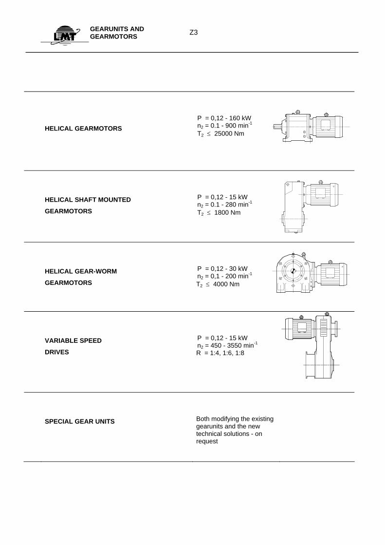
HELICAL GEARMOTORS
P = 0,12 - 160 kW n2 = 0.1 - 900 min-1 T2 ≤ 25000 Nm
HELICAL SHAFT MOUNTED
GEARMOTORS
P = 0,12 - 15 kW n2 = 0.1 - 280 min-1 T2 ≤ 1800 Nm
HELICAL GEAR-WORM
GEARMOTORS
P = 0,12 - 30 kW n2 = 0,1 - 200 min-1 T2 ≤ 4000 Nm
VARIABLE SPEED
DRIVES
P = 0,12 - 15 kW n2 = 450 - 3550 min-1 R = 1:4, 1:6, 1:8
SPECIAL GEAR UNITS
Both modifying the existing gearunits and the new technical solutions - on request
Z4HELICAL AND
HELICAL-SHAFT MOUNTED GEARMOTORS
Introduction Helical and helical-shaft mounted gearmotors based on modular assembly system enable the optimal solutions for numerous drives of low speed operating machines which cannot be resolved any more using an electric motor. Modular system enables a great deal of gear alternatives with a minimum of both standard and type components and assemblies the system consists of. All of these gearunits are standardly produced and supplied as helical, helical-shaft mounted or - in combination with el.motors or input assemblies. The gears are distinguished by their simple coupling possibilities with electric motors as gear motors which enable a good alignement of the electric motor shaft and first gear shaft providing a long-lasting and reliable functioning of the gearunits. There is no need for the motor foundation and the compactness is also better. The electrical characteristics of the electric motors intended for gears which are used at motor gears are identical with standard IEC electric motors intended for industrial purposes. Their mechanical characteristics slightly differ from standard IEC electric motors as far as their flange and shaft end coupling dimensions and reinforced bearings are concerned. There is a possibility of mounting IEC motors with a special adapter for IEC motors (up to 200 mm shaft height, I.E. up to 30 kW) with an elastic coupling incorporated. The gearunits can also be supplied without electric motors as motorless gearunits if the subassembly B, BT is fitted to the input side of both helical or shaft-mounted gearunits.
Technical Execution The gearunits′ housings are made of grey iron, they are mechanically and thermally stable and can reduce the vibrations. Their construction is meant for continuous duty. They are determined by the max. output torque. There are two types of executions of the housings: with or without feet. The gears are made of alloyed steel by turning and milling (planing, if necessary). The desired characteristics are obtained by thermal processing and grinding of the surfaces. Cautious manufacturing and permanent control assure high quality and reliability of different stages of transmission (according to standard series R20/3). The gear shafts are produced of plain refined steel distinguished by the best characteristics as to hardness, rigidity and tenacity. The bearings are roller bearings that make the assembly more simple and assure high carrying capacity. Lubrication by splashing oil creates the oil film between the teeth in contact eliminating the metal contact. Besides that, lubricating oil leads the thermal losses onto the housing and protects from corrosion in working and stand-still condition of the gearunit. Tightening, as a very important element when the driving security is concerned, is done by means of both high quality shaft tighteners and tightening caps which prevent the oil leakage and the penetration of the dust into the gearunit. Colouring and antirust protection is standardly performed with a basic colour onto which a finishing layer of RAL 7001 GREY colour is painted. The processed surfaces are protected with a thin antirust coating. It is possible to request some other kind of colouring and protection.
Power, Torque and Speed Values of output power greaded acording to ISO 497/73 and torque values from selection tables refer to the standard execution, standard ambiental conditions and also standard lubrication of gearunits and motor gears. Motor output values given in tables are just orientational ones. In every single case of application the crucial parameter is the output torque at requested output r.p.m. The output r.p.m. values given in tables for the selection of the gearunits are rounded off to the standard values according to R20 series. The real r.p.m. value is attainable from motor rated r.p.m. and gear ratio, and depends on real loading and changes of the network tension.
Efficiency The efficiency is defined mainly by rolling losses of teeth and bedding of the bearings. Depending on the number of stages of the gearunit the efficiency of the basic gearunit is between 94 and 98%. In case of a combination of basic and additional gearunit the efficiency is between 85-92%.
Gear Unit Weight Since the oil quantity depends on mounting position the gearunit masses given in the tables refer to the motor and motorless gearunits without oil filling. The oil masses are given in another table.
Modular System
Z5HELICAL AND
HELICAL-SHAFT MOUNTED GEARMOTORS
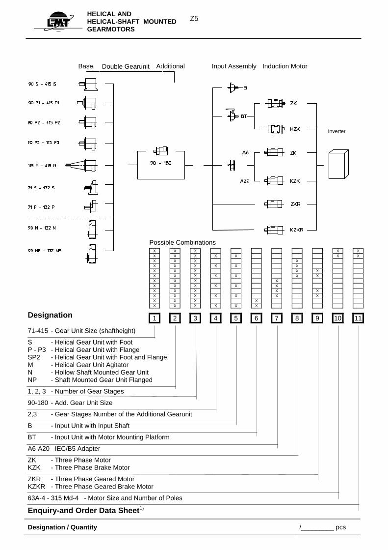
Base Additional Input Assembly Induction Motor
Designation 71-415 - Gear Unit Size (shaftheight)
S - Helical Gear Unit with Foot P - P3 - Helical Gear Unit with Flange SP2 - Helical Gear Unit with Foot and Flange M - Helical Gear Unit Agitator N - Hollow Shaft Mounted Gear Unit NP - Shaft Mounted Gear Unit Flanged
1, 2, 3 - Number of Gear Stages
90-180 - Add. Gear Unit Size
2,3 - Gear Stages Number of the Additional Gearunit
B - Input Unit with Input Shaft
BT - Input Unit with Motor Mounting Platform
A6-A20 - IEC/B5 Adapter
ZK - Three Phase Motor KZK - Three Phase Brake Motor
ZKR - Three Phase Geared Motor KZKR - Three Phase Geared Brake Motor
63A-4 - 315 Md-4 - Motor Size and Number of Poles
Enquiry-and Order Data Sheet1)
Designation / Quantity /_________ pcs
Possible Combinations X X X X X X X X X X X X X X X X X X X X X X X X X X X X X X X X X X X X X X X X X X X X X X X X X X X X X X X X X X X X X X X X X X
1 2 3 4 5 6 7 8 9 10 11
Inverter
Double Gearunit
Z6HELICAL AND
HELICAL-SHAFT MOUNTED GEARMOTORS
_________________________________________________________
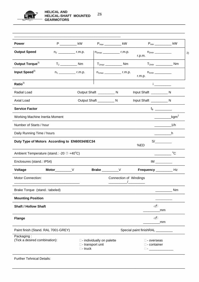
Power P _________ kW Pmax _________ kW Pmin _________ kW
Output Speed n2 _________ r.m.p. n2max _________ r.m.p. n2min _________ r.p.m.
Output Torque3) T2 _________ Nm T2max _________ Nm T2min _________ Nm
Input Speed3) n1 _________ r.m.p. n1max _________ r.m.p. n1min _________ r.m.p.
Ratio3) i _________
Radial Load Output Shaft _________ N Input Shaft _________ N
Axial Load Output Shaft _________ N Input Shaft _________ N
Service Factor fB _________
Working Machine Inertia Moment _________kgm2
Number of Starts / hour _________1/h
Daily Running Time / hours _________h
Duty Type of Motors According to EN60034/IEC34 S/_________ %ED
Ambient Temperature (stand.: -20 +40oC) _________ oC
Enclosures (stand.: IP54) IM _________
Voltage Motor_________V Brake _________V Frequency _________ Hz
Motor Connection: ___________________________________
Connection of Windings __________/_________
Brake Torque (stand.: tabeled) _________ Nm
Mounting Position _________
Shaft / Hollow Shaft _________mm
Flange _________mm
Paint finish (Stand. RAL 7001-GREY) Special paint finishRAL _________
Packaging : (Tick a desired combination):
- individually on palette - transport unit - truck
- overseas - container - _____________
Further Tehnical Details:
2)
Z7HELICAL AND
HELICAL-SHAFT MOUNTED GEARMOTORS
1) Data emphasized are obligatory when ordering 2) At two speed motors, variators′ and regulators′ appliance 3) For motorless gearunits
Drive Selection
The following metodology refers to gearmotors and motorless gears.
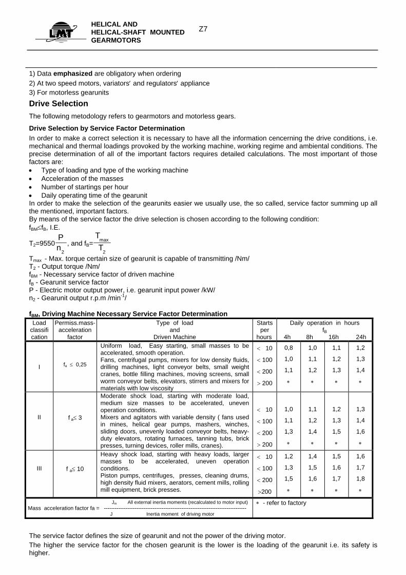
Drive Selection by Service Factor Determination In order to make a correct selection it is necessary to have all the information cencerning the drive conditions, i.e. mechanical and thermal loadings provoked by the working machine, working regime and ambiental conditions. The precise determination of all of the important factors requires detailed calculations. The most important of those factors are: • Type of loading and type of the working machine • Acceleration of the masses • Number of startings per hour • Daily operating time of the gearunit In order to make the selection of the gearunits easier we usually use, the so called, service factor summing up all the mentioned, important factors. By means of the service factor the drive selection is chosen according to the following condition: fBM≤fB, I.E.
T2=9550Pn
2
, and fB=TTmax
2
Tmax - Max. torque certain size of gearunit is capable of transmitting /Nm/ T2 - Output torque /Nm/ fBM - Necessary service factor of driven machine fB - Gearunit service factor P - Electric motor output power, i.e. gearunit input power /kW/ n2 - Gearunit output r.p.m /min-1/ fBM, Driving Machine Necessary Service Factor Determination
Load classification
Permiss.mass-acceleration
factor
Type of load and
Driven Machine
Starts per
hours
Daily operation in hours fB
4h 8h 16h 24h I
fa ≤ 0,25
Uniform load, Easy starting, small masses to be accelerated, smooth operation. Fans, centrifugal pumps, mixers for low density fluids, drilling machines, light conveyor belts, small weight cranes, bottle filling machines, moving screens, small worm conveyor belts, elevators, stirrers and mixers for materials with low viscosity
< 10
< 100
< 200
> 200
0,8
1,0
1,1
∗
1,0
1,1
1,2
∗
1,1
1,2
1,3
∗
1,2
1,3
1,4
∗
II
f a≤ 3
Moderate shock load, starting with moderate load, medium size masses to be accelerated, uneven operation conditions. Mixers and agitators with variable density ( fans used in mines, helical gear pumps, mashers, winches, sliding doors, unevenly loaded conveyor belts, heavy-duty elevators, rotating furnaces, tanning tubs, brick presses, turning devices, roller mills, cranes).
< 10
< 100
< 200
> 200
1,0
1,1
1,3
∗
1,1
1,2
1,4
∗
1,2
1,3
1,5
∗
1,3
1,4
1,6
∗
III
f a≤ 10
Heavy shock load, starting with heavy loads, larger masses to be accelerated, uneven operation conditions. Piston pumps, centrifuges, presses, cleaning drums, high density fluid mixers, aerators, cement mills, rolling mill equipment, brick presses.
< 10
< 100
< 200
>200
1,2
1,3
1,5
∗
1,4
1,5
1,6
∗
1,5
1,6
1,7
∗
1,6
1,7
1,8
∗
Jm All external inertia moments (recalculated to motor input) Mass acceleration factor fa = -------------------------------------------------------------------------------
J Inertia moment of driving motor
∗ - refer to factory
The service factor defines the size of gearunit and not the power of the driving motor. The higher the service factor for the chosen gearunit is the lower is the loading of the gearunit i.e. its safety is higher.
Z8HELICAL AND
HELICAL-SHAFT MOUNTED GEARMOTORS
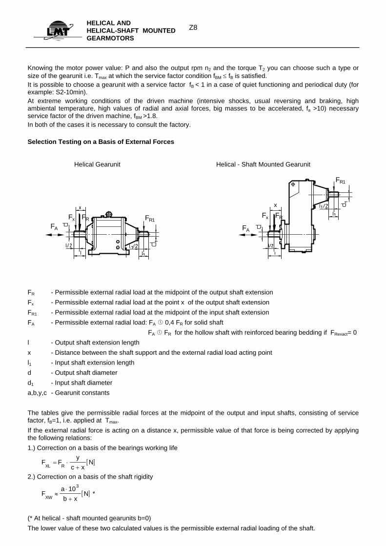
Knowing the motor power value: P and also the output rpm n2 and the torque T2 you can choose such a type or size of the gearunit i.e. Tmax at which the service factor condition fBM ≤ fB is satisfied. It is possible to choose a gearunit with a service factor fB < 1 in a case of quiet functioning and periodical duty (for example: S2-10min). At extreme working conditions of the driven machine (intensive shocks, usual reversing and braking, high ambiental temperature, high values of radial and axial forces, big masses to be accelerated, fa >10) necessary service factor of the driven machine, fBM >1.8. In both of the cases it is necessary to consult the factory. Selection Testing on a Basis of External Forces Helical Gearunit Helical - Shaft Mounted Gearunit
Fx FR Fx FR
FA FA
FR1
FR1
x
FR - Permissible external radial load at the midpoint of the output shaft extension Fx - Permissible external radial load at the point x of the output shaft extension FR1 - Permissible external radial load at the midpoint of the input shaft extension FA - Permissible external radial load: FA 0,4 FR for solid shaft FA FR for the hollow shaft with reinforced bearing bedding if FRexact= 0 l - Output shaft extension length x - Distance between the shaft support and the external radial load acting point l1 - Input shaft extension length d - Output shaft diameter d1 - Input shaft diameter a,b,y,c - Gearunit constants The tables give the permissible radial forces at the midpoint of the output and input shafts, consisting of service factor, fB=1, i.e. applied at Tmax. If the external radial force is acting on a distance x, permissible value of that force is being corrected by applying the following relations: 1.) Correction on a basis of the bearings working life
[ ]F Fy
c xN
XL R= ⋅
+
2.) Correction on a basis of the shaft rigidity
[ ]Fab x
NXW
≈⋅+103
*
(* At helical - shaft mounted gearunits b=0) The lower value of these two calculated values is the permissible external radial loading of the shaft.
Z9HELICAL AND
HELICAL-SHAFT MOUNTED GEARMOTORS
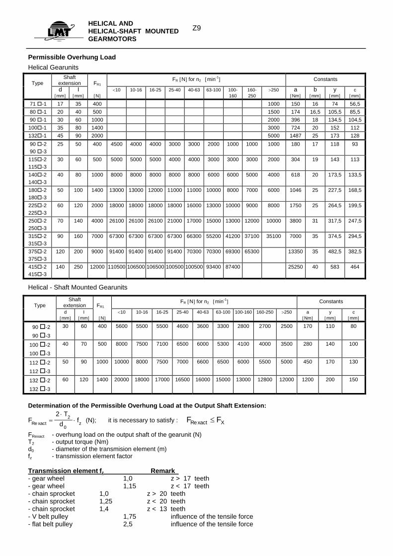
Permissible Overhung Load Helical Gearunits
Type
Shaft extension
FR1
FR [N] for n2 [min-1] Constants
d [mm]
I [mm]
[N]
<10 10-16 16-25 25-40 40-63 63-100 100-160
160-250
>250 a [Nm]
b [mm]
y [mm]
c [mm]
71 -1 17 35 400 1000 150 16 74 56,5 80 -1 20 40 500 1500 174 16,5 105,5 85,5 90 -1 30 60 1000 2000 396 18 134,5 104,5 100 -1 35 80 1400 3000 724 20 152 112 132 -1 45 90 2000 5000 1487 25 173 128 90 -2 90 -3
25 50 400 4500 4000 4000 3000 3000 2000 1000 1000 1000 180 17 118 93
115 -2 115 -3
30 60 500 5000 5000 5000 4000 4000 3000 3000 3000 2000 304 19 143 113
140 -2 140 -3
40 80 1000 8000 8000 8000 8000 8000 6000 6000 5000 4000 618 20 173,5 133,5
180 -2 180 -3
50 100 1400 13000 13000 12000 11000 11000 10000 8000 7000 6000 1046 25 227,5 168,5
225 -2 225 -3
60 120 2000 18000 18000 18000 18000 16000 13000 10000 9000 8000 1750 25 264,5 199,5
250 -2 250 -3
70 140 4000 26100 26100 26100 21000 17000 15000 13000 12000 10000 3800 31 317,5 247,5
315 -2 315 -3
90 160 7000 67300 67300 67300 67300 66300 55200 41200 37100 35100 7000 35 374,5 294,5
375 -2 375 -3
120 200 9000 91400 91400 91400 91400 70300 70300 69300 65300 13350 35 482,5 382,5
415 -2 415 -3
140 250 12000 110500 106500 106500 100500 100500 93400 87400 25250 40 583 464
Helical - Shaft Mounted Gearunits
Type
Shaft extension
FR1
FR [N] for n2 [min-1] Constants
d [mm]
I [mm]
[N]
<10 10-16 16-25 25-40 40-63 63-100 100-160 160-250 >250 a [Nm]
y [mm]
c [mm]
90 -2 90 -3
30 60 400 5600 5500 5500 4600 3600 3300 2800 2700 2500 170 110 80
100 -2 100 -3
40 70 500 8000 7500 7100 6500 6000 5300 4100 4000 3500 280 140 100
112 -2 112 -3
50 90 1000 10000 8000 7500 7000 6600 6500 6000 5500 5000 450 170 130
132 -2 132 -3
60 120 1400 20000 18000 17000 16500 16000 15000 13000 12800 12000 1200 200 150
Determination of the Permissible Overhung Load at the Output Shaft Extension:
FT
d fxact zRe =⋅
⋅2 2
0 (N); it is necessary to satisfy : F Fxact XRe ≤
FRexact - overhung load on the output shaft of the gearunit (N) T2 - output torque (Nm) d0 - diameter of the transmision element (m) fz - transmission element factor Transmission element fz Remark - gear wheel 1,0 z > 17 teeth - gear wheel 1,15 z < 17 teeth - chain sprocket 1,0 z > 20 teeth - chain sprocket 1,25 z < 20 teeth - chain sprocket 1,4 z < 13 teeth - V belt pulley 1,75 influence of the tensile force - flat belt pulley 2,5 influence of the tensile force
Z10HELICAL AND
HELICAL-SHAFT MOUNTED GEARMOTORS
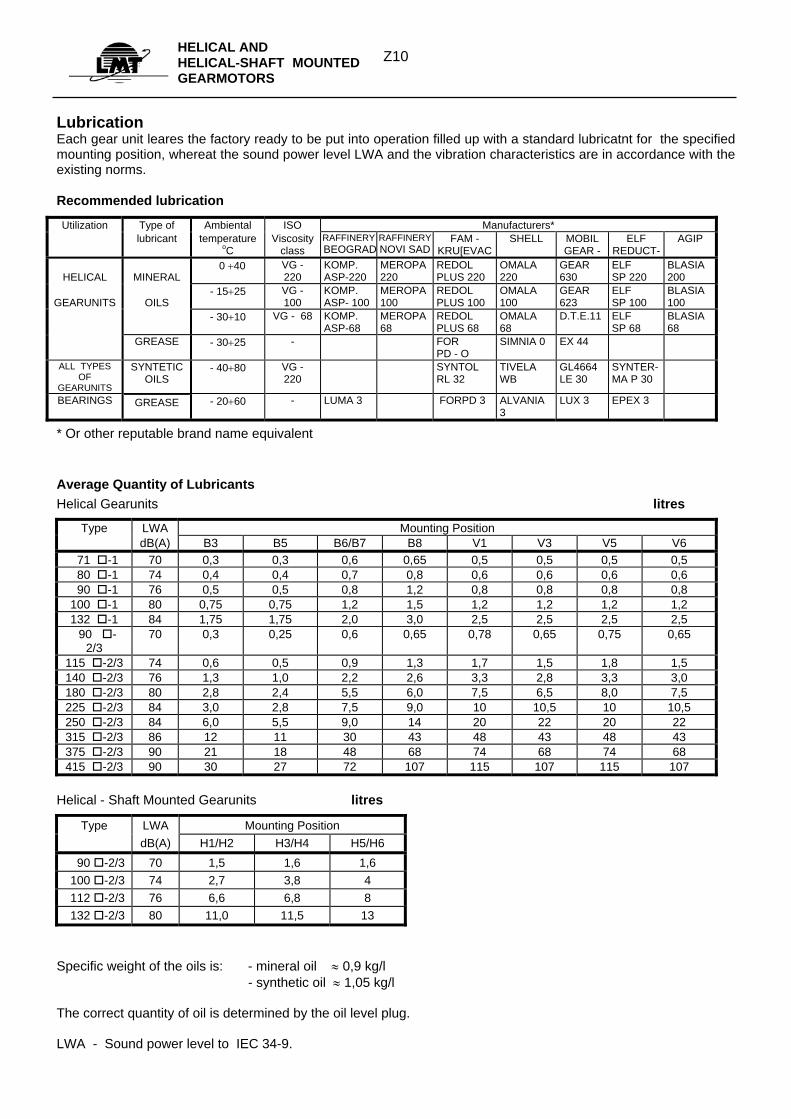
Lubrication Each gear unit leares the factory ready to be put into operation filled up with a standard lubricatnt for the specified mounting position, whereat the sound power level LWA and the vibration characteristics are in accordance with the existing norms. Recommended lubrication
Utilization Type of Ambiental ISO Manufacturers* lubricant temperature
oC Viscosity
class RAFFINERYBEOGRAD
RAFFINERYNOVI SAD
FAM - KRU[EVAC
SHELL MOBIL GEAR -
ELF REDUCT-
AGIP
HELICAL
MINERAL
0 +40 VG - 220
KOMP. ASP-220
MEROPA 220
REDOL PLUS 220
OMALA 220
GEAR 630
ELF SP 220
BLASIA 200
GEARUNITS
OILS
- 15+25 VG - 100
KOMP. ASP- 100
MEROPA 100
REDOL PLUS 100
OMALA 100
GEAR 623
ELF SP 100
BLASIA 100
- 30+10 VG - 68 KOMP. ASP-68
MEROPA 68
REDOL PLUS 68
OMALA 68
D.T.E.11 ELF SP 68
BLASIA 68
GREASE - 30+25 - FOR PD - O
SIMNIA 0 EX 44
ALL TYPES OF
GEARUNITS
SYNTETIC OILS
- 40+80 VG - 220
SYNTOL RL 32
TIVELA WB
GL4664 LE 30
SYNTER-MA P 30
BEARINGS GREASE - 20+60 - LUMA 3 FORPD 3 ALVANIA 3
LUX 3 EPEX 3
* Or other reputable brand name equivalent
Average Quantity of Lubricants Helical Gearunits litres
Type LWA Mounting Position dB(A) B3 B5 B6/B7 B8 V1 V3 V5 V6
71 -1 70 0,3 0,3 0,6 0,65 0,5 0,5 0,5 0,5 80 -1 74 0,4 0,4 0,7 0,8 0,6 0,6 0,6 0,6 90 -1 76 0,5 0,5 0,8 1,2 0,8 0,8 0,8 0,8 100 -1 80 0,75 0,75 1,2 1,5 1,2 1,2 1,2 1,2 132 -1 84 1,75 1,75 2,0 3,0 2,5 2,5 2,5 2,5 90 -
2/3 70 0,3 0,25 0,6 0,65 0,78 0,65 0,75 0,65
115 -2/3 74 0,6 0,5 0,9 1,3 1,7 1,5 1,8 1,5 140 -2/3 76 1,3 1,0 2,2 2,6 3,3 2,8 3,3 3,0 180 -2/3 80 2,8 2,4 5,5 6,0 7,5 6,5 8,0 7,5 225 -2/3 84 3,0 2,8 7,5 9,0 10 10,5 10 10,5 250 -2/3 84 6,0 5,5 9,0 14 20 22 20 22 315 -2/3 86 12 11 30 43 48 43 48 43 375 -2/3 90 21 18 48 68 74 68 74 68 415 -2/3 90 30 27 72 107 115 107 115 107
Helical - Shaft Mounted Gearunits litres
Type LWA Mounting Position dB(A) H1/H2 H3/H4 H5/H6
90 -2/3 70 1,5 1,6 1,6 100 -2/3 74 2,7 3,8 4 112 -2/3 76 6,6 6,8 8 132 -2/3 80 11,0 11,5 13
Specific weight of the oils is: - mineral oil ≈ 0,9 kg/l - synthetic oil ≈ 1,05 kg/l The correct quantity of oil is determined by the oil level plug. LWA - Sound power level to IEC 34-9.
Z11
HELICAL AND HELICAL-SHAFT MOUNTED GEARMOTORS
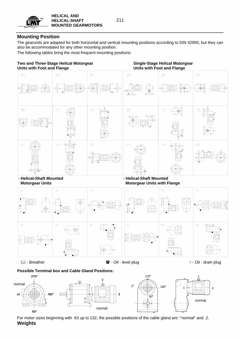
Mounting Position The gearunits are adapted for both horizontal and vertical mounting positions according to DIN 42950, but they can also be accommodated for any other mounting position. The following tables bring the most frequent mounting positions: Two and Three-Stage Helical Motorgear Single-Stage Helical Motorgear Units with Foot and Flange Units with Foot and Flange
- Helical-Shaft Mounted - Helical-Shaft Mounted Motorgear Units Motorgear Units with Flange
Possible Terminal box and Cable Gland Positions:
0o
270o
180o
90o
1
2
3
For motor sizes beginning with 63 up to 132, the possible positions of the cable gland are: ″normal″ and 2. Weights
normal normal
- Breather - Oil - level plug - Oil - drain plug
normal
Z12HELICAL AND
HELICAL-SHAFT MOUNTED GEARMOTORS
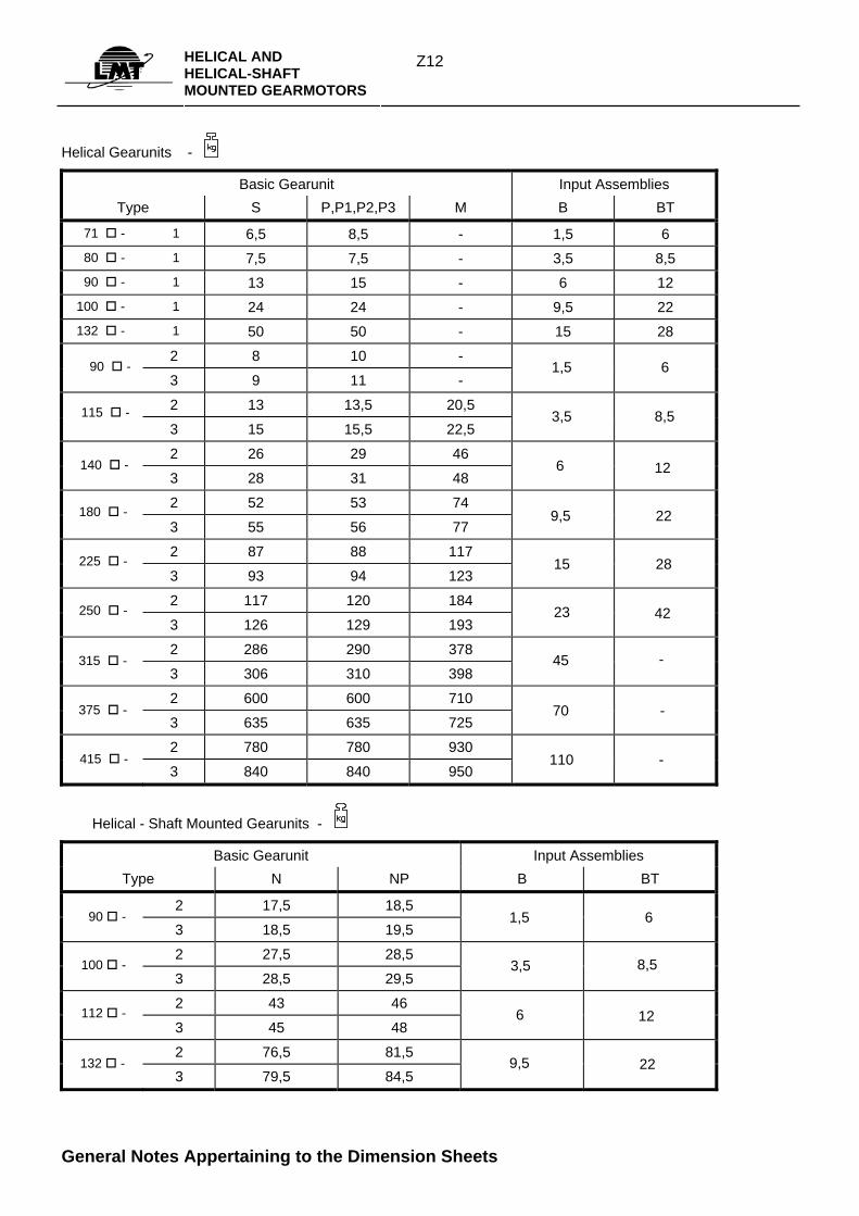
Helical Gearunits -
Basic Gearunit Input Assemblies Type S P,P1,P2,P3 M B BT
71 - 1 6,5 8,5 - 1,5 6 80 - 1 7,5 7,5 - 3,5 8,5 90 - 1 13 15 - 6 12 100 - 1 24 24 - 9,5 22 132 - 1 50 50 - 15 28
2 8 10 -
3 9 11 -
2 13 13,5 20,5
3 15 15,5 22,5
2 26 29 46
3 28 31 48
2 52 53 74
3 55 56 77
2 87 88 117
3 93 94 123
2 117 120 184
3 126 129 193
2 286 290 378
3 306 310 398
2 600 600 710
3 635 635 725
2 780 780 930
3 840 840 950
Helical - Shaft Mounted Gearunits -
Basic Gearunit Input Assemblies Type N NP B BT
2 17,5 18,5
3 18,5 19,5
2 27,5 28,5
3 28,5 29,5
2 43 46
3 45 48
2 76,5 81,5
3 79,5 84,5
General Notes Appertaining to the Dimension Sheets
90 -
115 -
140 -
180 -
225 -
250 -
315 -
375 -
415 -
90 -
100 -
112 -
132 -
6 1,5
8,5 3,5
12 6
22 9,5
28 15
42 23
- 45
- 70
- 110
6 1,5
8,5 3,5
6 12
22 9,5
Z13HELICAL AND
HELICAL-SHAFT MOUNTED GEARMOTORS
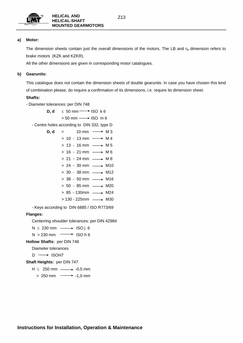
a) Motor:
The dimension sheets contain just the overall dimensions of the motors. The LB and rB dimension refers to
brake motors (KZK and KZKR).
All the other dimensions are given in corresponding motor catalogues.
b) Gearunits:
This catalogue does not contain the dimension sheets of double gearunits. In case you have chosen this kind
of combination please, do require a confirmation of its dimensions, i.e. require its dimension sheet.
Shafts: - Diameter tolerances: per DIN 748
D, d ≤ 50 mm ISO k 6 > 50 mm ISO m 6 - Centre holes according to DIN 332, type D
D, d < 10 mm M 3 > 10 - 13 mm M 4 > 13 - 16 mm M 5 > 16 - 21 mm M 6 > 21 - 24 mm M 8 > 24 - 30 mm M10 > 30 - 38 mm M12 > 38 - 50 mm M16 > 50 - 85 mm M20 > 85 - 130mm M24 > 130 - 225mm M30
- Keys according to DIN 6885 / ISO R773/69
Flanges: Centerring shoulder tolerances: per DIN 42984
N ≤ 230 mm ISO j 6 N > 230 mm ISO h 6
Hollow Shafts: per DIN 748 Diameter tolerances D ISOH7
Shaft Heights: per DIN 747
H ≤ 250 mm -0,5 mm > 250 mm -1,0 mm
Instructions for Installation, Operation & Maintenance
Z14HELICAL AND
HELICAL-SHAFT MOUNTED GEARMOTORS
Delivery and storage
Gearunits, i.e. motorgears are checked and verified in the Dept. of final control and then delivered prepared for running, filled up with lubricants in acordance with the desired mounting position. During warranty period the gearunits are to be opened just with a previous authorization of the manufacturer.
In case they are not meant for an immediate functioning all machine storage should be done indoors, in dry and dark conditions, in their own packaging material if possible.
Installation
In order to eliminate the possible resonant vibrations during exploitation, including all the negative consequences, a foundation stud or the supporting construction must be dimensioned in a way that the structure own frequency can differ min ±20% from the excitation dominant frequency.
The foundation studs or the supporting constructions themselves must be able to bear extraordinary break-down loadings.
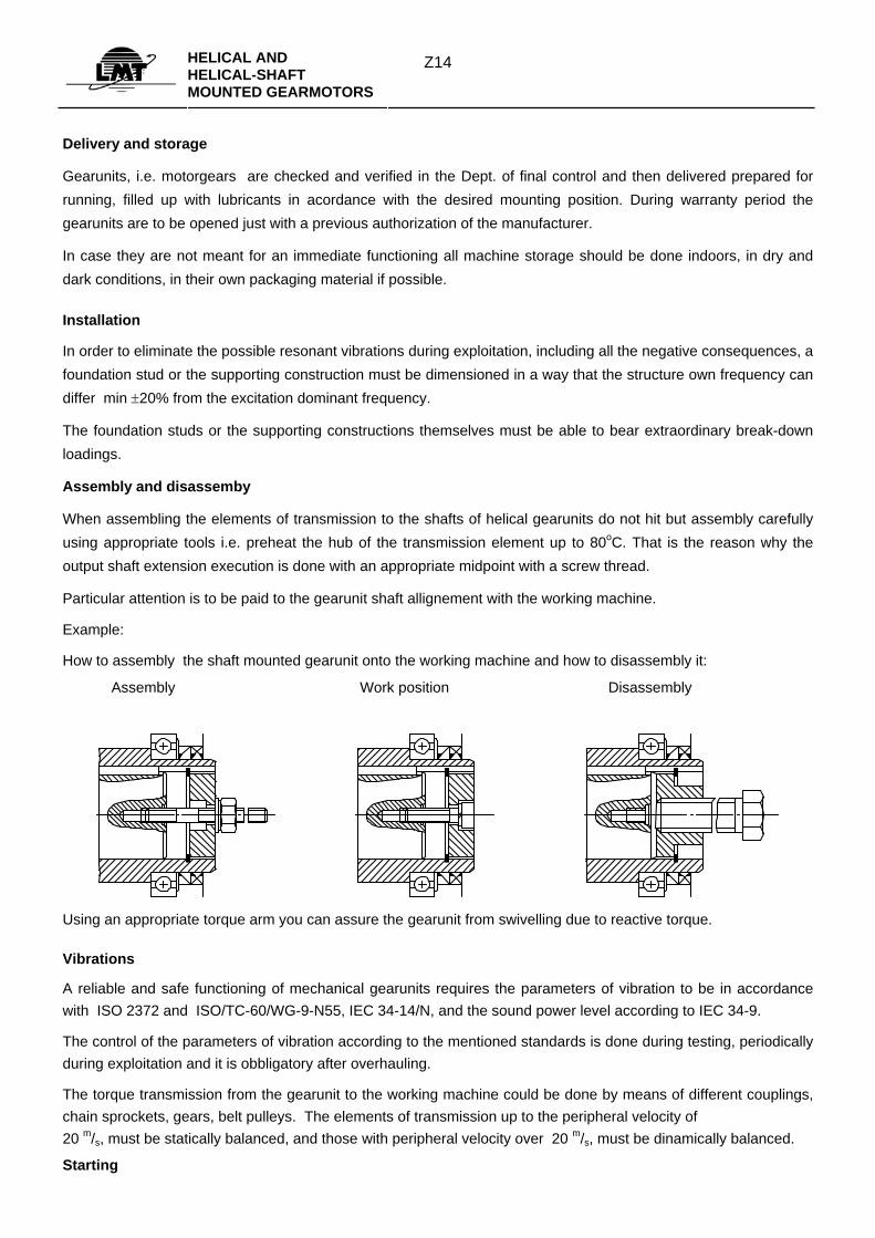
Assembly and disassemby
When assembling the elements of transmission to the shafts of helical gearunits do not hit but assembly carefully using appropriate tools i.e. preheat the hub of the transmission element up to 80oC. That is the reason why the output shaft extension execution is done with an appropriate midpoint with a screw thread.
Particular attention is to be paid to the gearunit shaft allignement with the working machine.
Example:
How to assembly the shaft mounted gearunit onto the working machine and how to disassembly it:
Assembly Work position Disassembly
Using an appropriate torque arm you can assure the gearunit from swivelling due to reactive torque.
Vibrations
A reliable and safe functioning of mechanical gearunits requires the parameters of vibration to be in accordance with ISO 2372 and ISO/TC-60/WG-9-N55, IEC 34-14/N, and the sound power level according to IEC 34-9.
The control of the parameters of vibration according to the mentioned standards is done during testing, periodically during exploitation and it is obbligatory after overhauling.
The torque transmission from the gearunit to the working machine could be done by means of different couplings, chain sprockets, gears, belt pulleys. The elements of transmission up to the peripheral velocity of 20 m/s, must be statically balanced, and those with peripheral velocity over 20 m/s, must be dinamically balanced.
Starting
Z15HELICAL AND
HELICAL-SHAFT MOUNTED GEARMOTORS
Prior to starting it is necessary to adjust the ventilation screw on the top of the gearunit in order to enable free air circulation. Every gearunit should be started along with the working machine first unloaded and then loaded.
It is also necessary to control the temperature and the vibrations of the motorgear housing, the buzzing and the motor current. These are the parameters of a well selected, properly mounted and adequatly loaded gearunit.
The level of the lubricant has to be in accordance with the gearunit mounting position.
Maintenance
The maintenance of gearunits and gearmotors consists of
• control of gearunit and motor temperature
• control of motor current, voltage supply
• control of buzzing and vibrations
• control of oil (level, foaming, presence of water, viscosity, regreasing)
Bearings lubricated with grease must not be completely filled up in order to avoid overheating.
After 3000 operating hours (at least once in a six months) it is necessary to do the oil checkup or to change it, if necessary.
Independently from the gearunit operating hours it is recommendable to change the mineral oil at least after two years (not longer than 10000 h), and as to the syntetic oil the recommendable period is 4 years (not longer than 20000 h). Oils of different makes are not to be mixed up.
At gearunits the oil change is to be done at standstill and in hot driving condition. After the old has been drained out and after cleaning the housing the new oil is being put in through the airport, up to the oil level aperture.
Up to this level also the relubricating is done, if necessary.
If it is necessary to take off the motor during the period of exploitation care should be taken not to damage the teeth on the gearunit′s first and second gear. The first gear fitted to the gear shaft extension is taken off using appropriate tools.
In the event of dismantling and assembly of the whole gearunit a special care should be taken to the accuracy of the shaft seals, sealing caps and klingerit seals.
Spare parts
When ordering spare parts, apart of the designation, it is necessary to give all the name plate data.
Spare parts sheet with the recommended substituting elements is obtainable on request.
Z16HELICAL GEARMOTORS HELICAL GEARUNITS
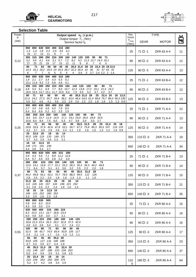
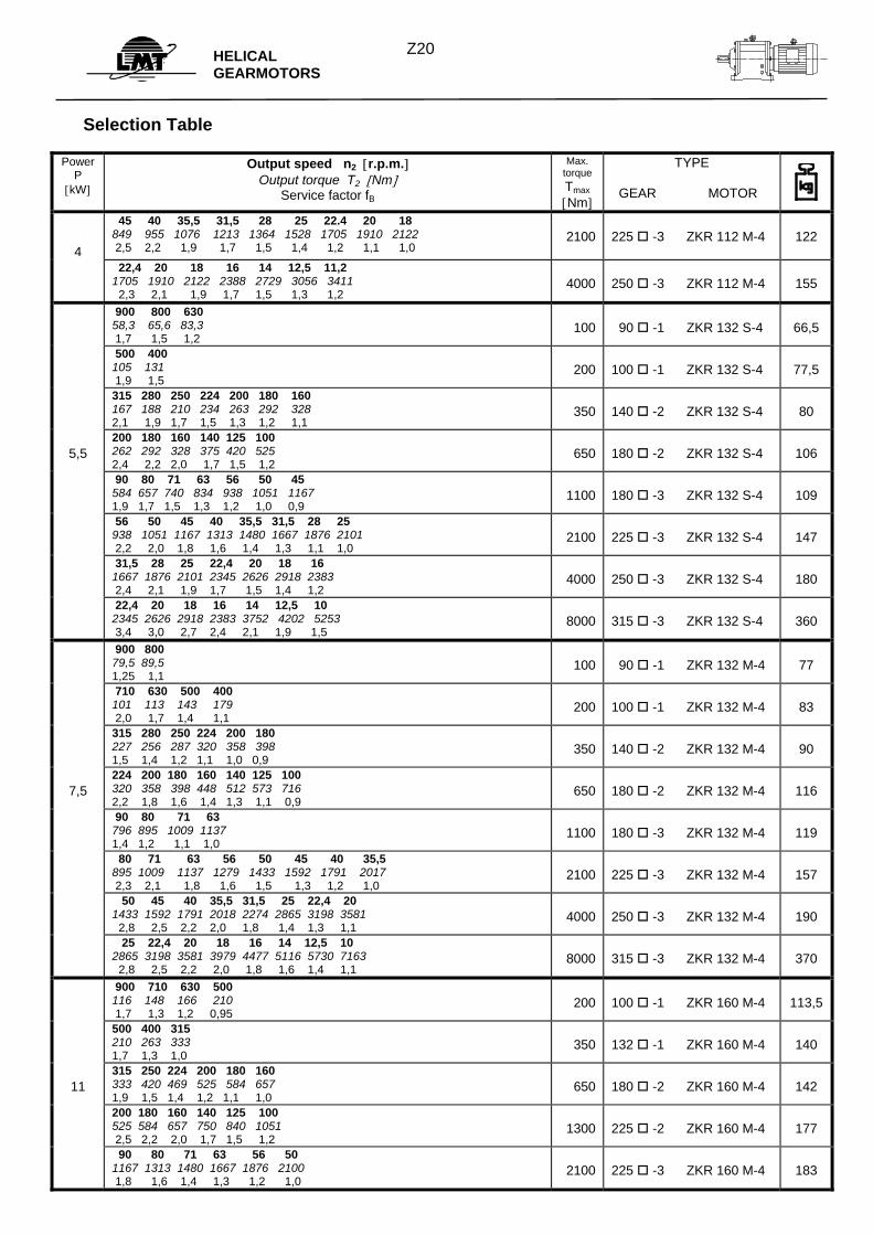
HELICAL GEARMOTORS
Selection Table
Power P
[kW]
Output speed n2 [r.p.m.] Output torque T2 [Nm]
Service factor fB
Max. torqueTmax [Nm]
TYPE
GEAR MOTOR
900 800 630 500 400 315 280 1,3 1,4 1,8 2,3 2,9 3,6 4,1 19 17 13 11 8 7 6
25
71 -1 ZKR 63 A-4
11
0,12
355 315 280 250 224 200 160 140 125 100 90 80 71 3,2 3,6 4,1 4,6 5,1 5,7 7,2 8,2 9,2 11,5 12,7 14,3 16,1 27 25 22 19 17 15 12 11 9 8 7 6 5
90
90 -2 ZKR 63 A-4
12
80 71 63 56 50 45 40 35,5 31,5 28 25 22,4 20 18 12,5 14,3 16,1 18,2 20,5 23 25,5 28,7 32,3 36,4 41 46 51 57 63 91 8 7 7 6 5 5 4 4 3,4 3 2,7 2,4 2,2 2 1,4
125
90 -3 ZKR 63 A-4
13
900 800 630 500 400 315 280 1,9 2,1 2,7 3,4 4,3 5,5 6,1 13,1 11,6 9,2 7,3 5,8 4,6 4,1
25
71 -1 ZKR 63 B-4
12
0,18
355 315 280 250 224 200 160 140 125 100 90 80 71 4,8 5,5 6,1 6,9 7,7 8,6 10,7 12,3 13,8 17,2 19,1 21,5 24,2 18,6 16,5 14,7 13,1 11,7 10,5 8,4 7,3 6,5 5,2 4,7 4,2 3,7
90
90 -2 ZKR 63 B-4
12
80 71 63 56 50 45 40 35,5 31,5 28 25 22,4 20 18 12,521,5 24,2 27,3 30,7 34,4 38,2 43,0 48,4 54,6 61,4 68,8 76,7 86,0 95,5 138 5,8 5,2 4,6 4,1 3,6 3,3 2,9 2,6 2,3 2,0 1,8 1,6 1,5 1,3 0,9
125
90 -3 ZKR 63 B-4
13
900 800 630 500 400 315 280 2,7 3,0 3,8 4,8 6,0 7,6 8,5 9,4 8,4 6,6 5,2 4,2 3,3 2,9
25
71 -1 ZKR 71 A-4
12
280 250 224 200 160 140 125 100 90 80 71 8,5 9,6 10,7 11,9 14,9 17,1 19,1 23,9 26,5 29,8 33,6 10,6 9,4 8,4 7,5 6,0 5,3 4,7 3,8 3,4 3,0 2,7
90
90 -2 ZKR 71 A-4
13
0,25
80 71 63 56 50 45 40 35,5 31,5 28 25 22,4 20 18 29,8 33,6 37,9 42,6 47,8 53,1 59,7 67,3 75,8 85,3 95,5 107 119 133 4,2 3,7 3,3 2,9 2,6 2,4 2,1 1,9 1,6 1,5 1,3 1,2 1,0 0,9
125
90 -3 ZKR 71 A-4
14
25 22,5 20 18 16 14 95,5 106 119 133 149 171 3,7 3,3 2,9 2,6 2,3 2,1
350
115 -3 ZKR 71 A-4
19
16 14 12,5 10 149 171 191 239 4,4 3,8 3,4 2,7
650
140 -3 ZKR 71 A-4
34
900 800 630 500 400 315 280 3,9 4,4 5,6 7,1 8,8 11,2 12,6 6,4 5,7 4,5 3,5 2,8 2,2 2,0
25
71 -1 ZKR 71 B-4
13
280 250 224 200 160 140 125 100 90 80 71 12,6 14,1 15,8 17,7 22,1 25,2 28,3 35,3 39,3 44,2 49,8 7,1 6,4 5,7 5,1 4,1 3,6 3,2 2,5 2,3 2,0 1,8
90
90 -2 ZKR 71 B-4
14
0,37
80 71 63 56 50 45 40 35,5 31,5 28 44,2 49,8 56,1 63,1 70,7 78,5 88,3 99,5 112 126 2,8 2,5 2,2 2,0 1,8 1,6 1,4 1,3 1,1 1,0
125
90 -3 ZKR 71 B-4
15
31,5 28 25 22,5 20 18 16 14 112 126 141 157 143 196 221 252 3,1 2,8 2,5 2,2 2,4 1,8 1,6 1,4
350
115 -3 ZKR 71 B-4
21
18 16 14 12,5 10 196 221 252 283 353 3,3 2,9 2,6 2,3 1,8
650
140 -3 ZKR 71 B-4
35
900 800 630 500 5,8 6,6 8,3 10,5 4,3 3,8 3,0 2,4
25
71 -1 ZKR 80 A-4
15
630 500 400 315 280 224 8,3 10,5 13,1 16,7 18,8 23,4 6,0 4,8 3,8 3,0 2,7 2,1
50
80 -1 ZKR 80 A-4
16
280 250 224 200 180 160 140 125 18,8 21,0 23,4 26,3 29,2 32,8 37,5 42,0 4,8 4,3 3,8 3,4 3,1 2,7 2,4 2,1
90
90 -2 ZKR 80 A-4
16
0,55
100 90 80 71 63 56 50 45 52,5 58 65,7 74,0 83,4 93,8 105 117 2,4 2,1 1,9 1,7 1,5 1,3 1,2 1,1
125
90 -3 ZKR 80 A-4
17
56 50 45 40 35,5 28 93,8 105 117 131 148 188 3,7 3,3 3,0 2,7 2,4 1,9
350
115 -3 ZKR 80 A-4
23
40 35,5 31,5 28 25 22,4 20 131 148 167 188 210 234 263 5,0 4,4 3,9 3,5 3,1 2,8 2,5
650
140 -3 ZKR 80 A-4
37
25 22,4 20 18 16 14 210 234 263 292 328 375 5,2 4,7 4,2 3,8 3,4 2,9
110
0
180 -3 ZKR 80 A-4
64
Z17
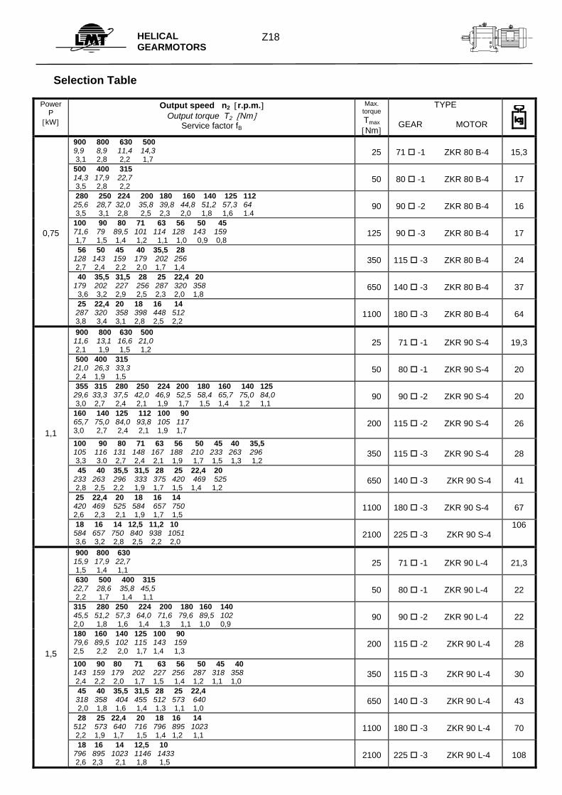
HELICAL GEARMOTORS
Selection Table
Power P
[kW]
Output speed n2 [r.p.m.] Output torque T2 [Nm]
Service factor fB
Max. torque Tmax [Nm]
TYPE
GEAR MOTOR
900 800 630 500 9,9 8,9 11,4 14,3 3,1 2,8 2,2 1,7
25
71 -1 ZKR 80 B-4
15,3
500 400 315 14,3 17,9 22,7 3,5 2,8 2,2
50
80 -1 ZKR 80 B-4
17
280 250 224 200 180 160 140 125 112 25,6 28,7 32,0 35,8 39,8 44,8 51,2 57,3 64 3,5 3,1 2,8 2,5 2,3 2,0 1,8 1,6 1.4
90
90 -2 ZKR 80 B-4
16
0,75
100 90 80 71 63 56 50 45 71,6 79 89,5 101 114 128 143 159 1,7 1,5 1,4 1,2 1,1 1,0 0,9 0,8
125
90 -3 ZKR 80 B-4
17
56 50 45 40 35,5 28 128 143 159 179 202 256 2,7 2,4 2,2 2,0 1,7 1,4
350
115 -3 ZKR 80 B-4
24
40 35,5 31,5 28 25 22,4 20 179 202 227 256 287 320 358 3,6 3,2 2,9 2,5 2,3 2,0 1,8
650
140 -3 ZKR 80 B-4
37
25 22,4 20 18 16 14 287 320 358 398 448 512 3,8 3,4 3,1 2,8 2,5 2,2
1100
180 -3 ZKR 80 B-4
64
900 800 630 500 11,6 13,1 16,6 21,0 2,1 1,9 1,5 1,2
25
71 -1 ZKR 90 S-4
19,3
500 400 315 21,0 26,3 33,3 2,4 1,9 1,5
50
80 -1 ZKR 90 S-4
20
355 315 280 250 224 200 180 160 140 125 29,6 33,3 37,5 42,0 46,9 52,5 58,4 65,7 75,0 84,0 3,0 2,7 2,4 2,1 1,9 1,7 1,5 1,4 1,2 1,1
90
90 -2 ZKR 90 S-4
20
1,1
160 140 125 112 100 90 65,7 75,0 84,0 93,8 105 117 3,0 2,7 2,4 2,1 1,9 1,7
200
115 -2 ZKR 90 S-4
26
100 90 80 71 63 56 50 45 40 35,5 105 116 131 148 167 188 210 233 263 296 3,3 3.0 2,7 2,4 2,1 1,9 1,7 1,5 1,3 1,2
350
115 -3 ZKR 90 S-4
28
45 40 35,5 31,5 28 25 22,4 20 233 263 296 333 375 420 469 525 2,8 2,5 2,2 1,9 1,7 1,5 1,4 1,2
650
140 -3 ZKR 90 S-4
41
25 22,4 20 18 16 14 420 469 525 584 657 750 2,6 2,3 2,1 1,9 1,7 1,5
1100
180 -3 ZKR 90 S-4
67
18 16 14 12,5 11,2 10 584 657 750 840 938 1051 3,6 3,2 2,8 2,5 2,2 2,0
2100
225 -3 ZKR 90 S-4
106
900 800 630 15,9 17,9 22,7 1,5 1,4 1,1
25
71 -1 ZKR 90 L-4
21,3
630 500 400 315 22,7 28,6 35,8 45,5 2,2 1,7 1,4 1,1
50
80 -1 ZKR 90 L-4
22
315 280 250 224 200 180 160 140 45,5 51,2 57,3 64,0 71,6 79,6 89,5 102 2,0 1,8 1,6 1,4 1,3 1,1 1,0 0,9
90
90 -2 ZKR 90 L-4
22
1,5
180 160 140 125 100 90 79,6 89,5 102 115 143 159 2,5 2,2 2,0 1,7 1,4 1,3
200
115 -2 ZKR 90 L-4
28
100 90 80 71 63 56 50 45 40 143 159 179 202 227 256 287 318 358 2,4 2,2 2,0 1,7 1,5 1,4 1,2 1,1 1,0
350
115 -3 ZKR 90 L-4
30
45 40 35,5 31,5 28 25 22,4 318 358 404 455 512 573 640 2,0 1,8 1,6 1,4 1,3 1,1 1,0
650
140 -3 ZKR 90 L-4
43
28 25 22,4 20 18 16 14 512 573 640 716 796 895 1023 2,2 1,9 1,7 1,5 1,4 1,2 1,1
1100
180 -3 ZKR 90 L-4
70
18 16 14 12,5 10 796 895 1023 1146 1433 2,6 2,3 2,1 1,8 1,5
2100
225 -3 ZKR 90 L-4
108
Z18
HELICAL GEARMOTORS
Selection Table
Power P
[kW]
Output speed n2 [r.p.m.] Output torque T2 [Nm]
Service factor fB
Max. torque Tmax [Nm]
TYPE
GEAR MOTOR
900 800 630 500 23,3 26,2 33,3 42,0 2,1 1,9 1,5 1,2
50
80 -1 ZKR 100 L-4
26,3
500 400 42,0 52,0 2,3 1,9
100
90 -1 ZKR 100 L-4
31,8
280 250 224 200 180 160 140 125 75,0 84,0 93,8 105 117 131 150 168 2,7 2,4 2,1 1,9 1,7 1,5 1,3 1,2
200
115 -2 ZKR 100 L-4
32
100 90 80 210 233 263 1,7 1,5 1,3
350
115 -3 ZKR 100 L-4
34
2,2
140 125 112 100 150 168 188 210 2,1 2,1 1,9 1,7
350
140 -2 ZKR 100 L-4
45
90 80 71 63 56 50 45 40 35,5 31.5 233 263 256 333 375 420 467 525 592 667 2,8 2,5 2,1 1,9 1,7 1,5 1,4 1,2 1,1 1,0
650
140 -3 ZKR 100 L-4
47
45 40 35,5 31,5 28 25 20 467 525 591 667 750 840 1051 2,4 2,1 1,8 1,6 1,5 1,3 1,0
1100
180 -3 ZKR 100 L-4
74
28 25 22.4 20 18 16 14 750 840 938 1051 1167 1313 1501 2,8 2,5 2,2 2,0 1,8 1,6 1,4
2100
225 -3 ZKR 100 L-4
112
18 16 14 12,5 11,2 1167 1313 1501 1681 1876 3,4 3,0 2,7 2,4 2,1
4000
250 -3 ZKR 100 L-4
145
900 800 630 500 400 31,8 35,8 45,5 57 71 3,1 2,8 2,2 1,7 1,4
100
90 -1 ZKR 100 Ld-4
35
500 400 315 57,3 71,6 133 3,5 2,8 1,5
200
100 -1 ZKR 100 Ld-4
46
315 280 250 224 200 180 160 140 125 91,0 102 115 128 143 159 179 205 229 2,2 2,0 1,7 1,6 1,4 1,3 1,1 1,0 0,9
200
115 -2 ZKR 100 Ld-4
35
100 90 80 287 318 358 1,2 1,1 1,0
350
115 -3 ZKR 100 Ld-4
37
3
160 140 125 112 100 179 205 229 256 287 2,0 1,5 1,7 1,4 1,2
350
140 -2 ZKR 100 Ld-4
48
100 90 71 80 63 56 50 45 287 318 403 358 455 512 573 636 2,2 2 1,6 1,8 1,4 1,3 1,1 1,0
650
140 -3 ZKR 100 Ld-4
50
71 63 56 50 45 40 35,5 31,5 404 455 512 573 637 716 807 910 2,7 2,4 2,2 1,9 1,7 1,5 1,3 1,2
1100
180 -3 ZKR 100 Ld-4
77
45 40 35,5 31,5 28 25 22.4 20 18 16 637 716 807 910 1023 1146 1279 1433 1592 1791 3,3 2,9 2,6 2,3 2,1 1,8 1,6 1,5 1,3 1,2
2100
225 -3 ZKR 100 Ld-4
115
20 18 16 14 12,5 11,2 1433 1592 1791 2046 2292 2558 2,8 2,5 2,2 2,0 1,7 1,6
4000
250 -3 ZKR 100 Ld-4
148
900 800 630 500 400 42,4 47,7 60,6 76 95 2,3 2,1 1,6 1,3 1,1
100
90 -1 ZKR 112 M-4
41,4
500 400 76,4 95,5 2,6 2,1
200
100 -1 ZKR 112 M-4
52,4
4
315 280 250 224 200 180 160 140 125 112 100 121 136 153 171 191 212 239 273 306 341 382 2,9 2,6 2,3 2,1 1,8 1,6 1,5 1,3 1,1 1,0 0,9
350
140 -2 ZKR 112 M-4
55
100 90 80 71 63 382 424 478 538 606 1,7 1,5 1,4 1,2 1,1
650
140 -3 ZKR 112 M-4
57
90 80 71 63 56 50 45 40 424 478 538 606 682 764 849 955 2,6 2,3 2,0 1,8 1,6 1,4 1,3 1,2
1100
180 -3 ZKR 112 M-4
84
Z19
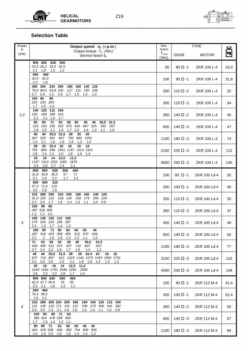
HELICAL GEARMOTORS
Selection Table
Power P
[kW]
Output speed n2 [r.p.m.] Output torque T2 [Nm]
Service factor fB
Max. torque Tmax [Nm]
TYPE
GEAR MOTOR
4
45 40 35,5 31,5 28 25 22.4 20 18 849 955 1076 1213 1364 1528 1705 1910 2122 2,5 2,2 1,9 1,7 1,5 1,4 1,2 1,1 1,0
2100
225 -3 ZKR 112 M-4
122
22,4 20 18 16 14 12,5 11,2 1705 1910 2122 2388 2729 3056 3411 2,3 2,1 1,9 1,7 1,5 1,3 1,2
4000
250 -3 ZKR 112 M-4
155
900 800 630 58,3 65,6 83,3 1,7 1,5 1,2
100
90 -1 ZKR 132 S-4
66,5
500 400 105 131 1,9 1,5
200
100 -1 ZKR 132 S-4
77,5
315 280 250 224 200 180 160 167 188 210 234 263 292 328 2,1 1,9 1,7 1,5 1,3 1,2 1,1
350
140 -2 ZKR 132 S-4
80
5,5
200 180 160 140 125 100 262 292 328 375 420 525 2,4 2,2 2,0 1,7 1,5 1,2
650
180 -2 ZKR 132 S-4
106
90 80 71 63 56 50 45 584 657 740 834 938 1051 1167 1,9 1,7 1,5 1,3 1,2 1,0 0,9
1100
180 -3 ZKR 132 S-4
109
56 50 45 40 35,5 31,5 28 25 938 1051 1167 1313 1480 1667 1876 2101 2,2 2,0 1,8 1,6 1,4 1,3 1,1 1,0
2100
225 -3 ZKR 132 S-4
147
31,5 28 25 22,4 20 18 16 1667 1876 2101 2345 2626 2918 2383 2,4 2,1 1,9 1,7 1,5 1,4 1,2
4000
250 -3 ZKR 132 S-4
180
22,4 20 18 16 14 12,5 10 2345 2626 2918 2383 3752 4202 5253 3,4 3,0 2,7 2,4 2,1 1,9 1,5
8000
315 -3 ZKR 132 S-4
360
900 800 79,5 89,5 1,25 1,1
100
90 -1 ZKR 132 M-4
77
710 630 500 400 101 113 143 179 2,0 1,7 1,4 1,1
200
100 -1 ZKR 132 M-4
83
315 280 250 224 200 180 227 256 287 320 358 398 1,5 1,4 1,2 1,1 1,0 0,9
350
140 -2 ZKR 132 M-4
90
7,5
224 200 180 160 140 125 100 320 358 398 448 512 573 716 2,2 1,8 1,6 1,4 1,3 1,1 0,9
650
180 -2 ZKR 132 M-4
116
90 80 71 63 796 895 1009 1137 1,4 1,2 1,1 1,0
1100
180 -3 ZKR 132 M-4
119
80 71 63 56 50 45 40 35,5 895 1009 1137 1279 1433 1592 1791 2017 2,3 2,1 1,8 1,6 1,5 1,3 1,2 1,0
2100
225 -3 ZKR 132 M-4
157
50 45 40 35,5 31,5 25 22,4 20 1433 1592 1791 2018 2274 2865 3198 3581 2,8 2,5 2,2 2,0 1,8 1,4 1,3 1,1
4000
250 -3 ZKR 132 M-4
190
25 22,4 20 18 16 14 12,5 10 2865 3198 3581 3979 4477 5116 5730 7163 2,8 2,5 2,2 2,0 1,8 1,6 1,4 1,1
8000
315 -3 ZKR 132 M-4
370
900 710 630 500 116 148 166 210 1,7 1,3 1,2 0,95
200
100 -1 ZKR 160 M-4
113,5
500 400 315 210 263 333 1,7 1,3 1,0
350
132 -1 ZKR 160 M-4
140
11
315 250 224 200 180 160 333 420 469 525 584 657 1,9 1,5 1,4 1,2 1,1 1,0
650
180 -2 ZKR 160 M-4
142
200 180 160 140 125 100 525 584 657 750 840 1051 2,5 2,2 2,0 1,7 1,5 1,2
1300
225 -2 ZKR 160 M-4
177
90 80 71 63 56 50 1167 1313 1480 1667 1876 2100 1,8 1,6 1,4 1,3 1,2 1,0
2100
225 -3 ZKR 160 M-4
183
Z20
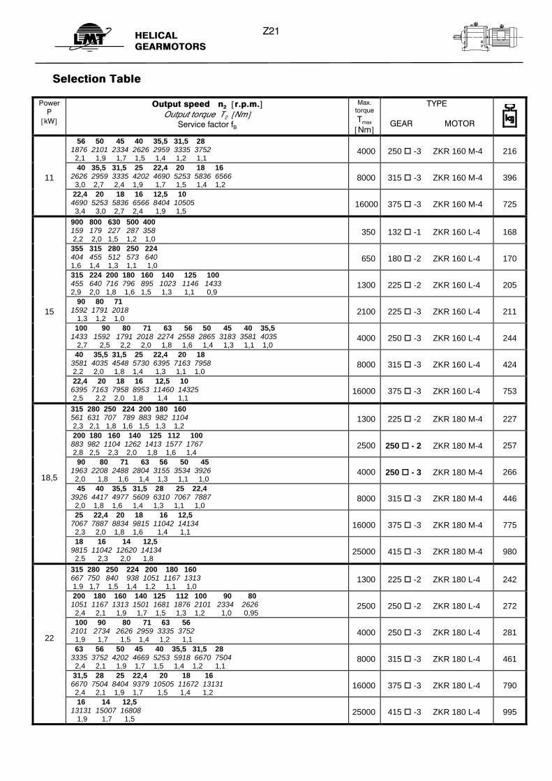
HELICAL GEARMOTORS
Selection Table
Power P
[kW]
Output speed n2 [r.p.m.] Output torque T2 [Nm]
Service factor fB
Max. torque Tmax [Nm]
TYPE
GEAR MOTOR
56 50 45 40 35,5 31,5 28 1876 2101 2334 2626 2959 3335 3752 2,1 1,9 1,7 1,5 1,4 1,2 1,1
4000
250 -3 ZKR 160 M-4
216
11
40 35,5 31,5 25 22,4 20 18 16 2626 2959 3335 4202 4690 5253 5836 6566 3,0 2,7 2,4 1,9 1,7 1,5 1,4 1,2
8000
315 -3 ZKR 160 M-4
396
22,4 20 18 16 12,5 10 4690 5253 5836 6566 8404 10505 3,4 3,0 2,7 2,4 1,9 1,5
16000
375 -3 ZKR 160 M-4
725
900 800 630 500 400 159 179 227 287 358 2,2 2,0 1,5 1,2 1,0
350
132 -1 ZKR 160 L-4
168
355 315 280 250 224 404 455 512 573 640 1,6 1,4 1,3 1,1 1,0
650
180 -2 ZKR 160 L-4
170
315 224 200 180 160 140 125 100 455 640 716 796 895 1023 1146 1433 2,9 2,0 1,8 1,6 1,5 1,3 1,1 0,9
1300
225 -2 ZKR 160 L-4
205
15
90 80 71 1592 1791 2018 1,3 1,2 1,0
2100
225 -3 ZKR 160 L-4
211
100 90 80 71 63 56 50 45 40 35,5 1433 1592 1791 2018 2274 2558 2865 3183 3581 4035 2,7 2,5 2,2 2,0 1,8 1,6 1,4 1,3 1,1 1,0
4000
250 -3 ZKR 160 L-4
244
40 35,5 31,5 25 22,4 20 18 3581 4035 4548 5730 6395 7163 7958 2,2 2,0 1,8 1,4 1,3 1,1 1,0
8000
315 -3 ZKR 160 L-4
424
22,4 20 18 16 12,5 10 6395 7163 7958 8953 11460 14325 2,5 2,2 2,0 1,8 1,4 1,1
16000
375 -3 ZKR 160 L-4
753
315 280 250 224 200 180 160 561 631 707 789 883 982 1104 2,3 2,1 1,8 1,6 1,5 1,3 1,2
1300
225 -2 ZKR 180 M-4
227
200 180 160 140 125 112 100 883 982 1104 1262 1413 1577 1767 2,8 2,5 2,3 2,0 1,8 1,6 1,4
2500
250 - 2 ZKR 180 M-4
257
18,5
90 80 71 63 56 50 45 1963 2208 2488 2804 3155 3534 3926 2,0 1,8 1,6 1,4 1,3 1,1 1,0
4000
250 - 3 ZKR 180 M-4
266
45 40 35,5 31,5 28 25 22,4 3926 4417 4977 5609 6310 7067 7887 2,0 1,8 1,6 1,4 1,3 1,1 1,0
8000
315 -3 ZKR 180 M-4
446
25 22,4 20 18 16 12,5 7067 7887 8834 9815 11042 14134 2,3 2,0 1,8 1,6 1,4 1,1
16000
375 -3 ZKR 180 M-4
775
18 16 14 12,5 9815 11042 12620 14134 2,5 2,3 2,0 1,8
25000
415 -3 ZKR 180 M-4
980
315 280 250 224 200 180 160 667 750 840 938 1051 1167 1313 1,9 1,7 1,5 1,4 1,2 1,1 1,0
1300
225 -2 ZKR 180 L-4
242
200 180 160 140 125 112 100 90 80 1051 1167 1313 1501 1681 1876 2101 2334 2626 2,4 2,1 1,9 1,7 1,5 1,3 1,2 1,0 0,95
2500
250 -2 ZKR 180 L-4
272
22
100 90 80 71 63 56 2101 2734 2626 2959 3335 3752 1,9 1,7 1,5 1,4 1,2 1,1
4000
250 -3 ZKR 180 L-4
281
63 56 50 45 40 35,5 31,5 28 3335 3752 4202 4669 5253 5918 6670 7504 2,4 2,1 1,9 1,7 1,5 1,4 1,2 1,1
8000
315 -3 ZKR 180 L-4
461
31,5 28 25 22,4 20 18 16 6670 7504 8404 9379 10505 11672 13131 2,4 2,1 1,9 1,7 1,5 1,4 1,2
16000
375 -3 ZKR 180 L-4
790
16 14 12,5 13131 15007 16808 1,9 1,7 1,5
25000
415 -3 ZKR 180 L-4
995
Z21
HELICAL GEARMOTORS
Selection Table
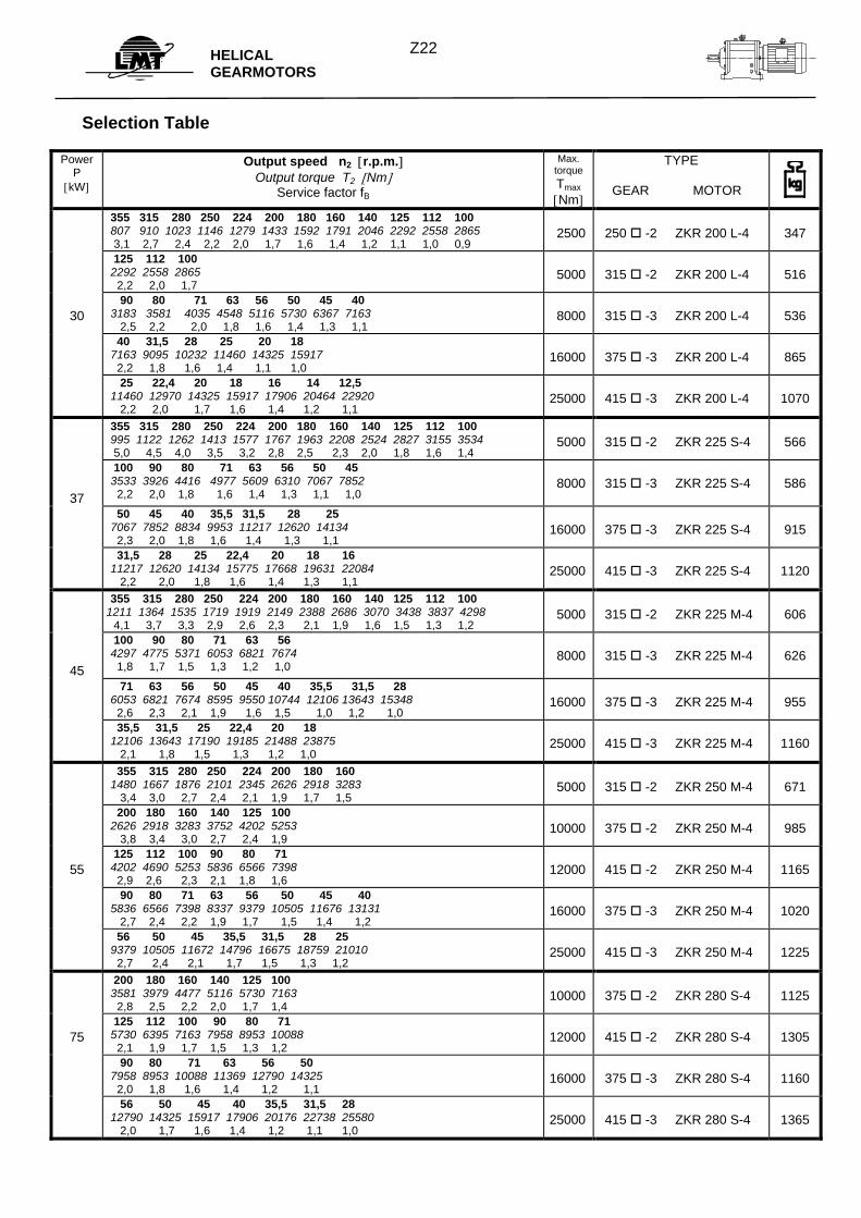
Power P
[kW]
Output speed n2 [r.p.m.] Output torque T2 [Nm]
Service factor fB
Max. torque Tmax [Nm]
TYPE
GEAR MOTOR
355 315 280 250 224 200 180 160 140 125 112 100 807 910 1023 1146 1279 1433 1592 1791 2046 2292 2558 2865 3,1 2,7 2,4 2,2 2,0 1,7 1,6 1,4 1,2 1,1 1,0 0,9
2500
250 -2 ZKR 200 L-4
347
125 112 100 2292 2558 2865 2,2 2,0 1,7
5000
315 -2 ZKR 200 L-4
516
30
90 80 71 63 56 50 45 40 3183 3581 4035 4548 5116 5730 6367 7163 2,5 2,2 2,0 1,8 1,6 1,4 1,3 1,1
8000
315 -3 ZKR 200 L-4
536
40 31,5 28 25 20 18 7163 9095 10232 11460 14325 15917 2,2 1,8 1,6 1,4 1,1 1,0
16000
375 -3 ZKR 200 L-4
865
25 22,4 20 18 16 14 12,5 11460 12970 14325 15917 17906 20464 22920 2,2 2,0 1,7 1,6 1,4 1,2 1,1
25000
415 -3 ZKR 200 L-4
1070
355 315 280 250 224 200 180 160 140 125 112 100 995 1122 1262 1413 1577 1767 1963 2208 2524 2827 3155 3534 5,0 4,5 4,0 3,5 3,2 2,8 2,5 2,3 2,0 1,8 1,6 1,4
5000
315 -2 ZKR 225 S-4
566
37
100 90 80 71 63 56 50 45 3533 3926 4416 4977 5609 6310 7067 7852 2,2 2,0 1,8 1,6 1,4 1,3 1,1 1,0
8000
315 -3 ZKR 225 S-4
586
50 45 40 35,5 31,5 28 25 7067 7852 8834 9953 11217 12620 14134 2,3 2,0 1,8 1,6 1,4 1,3 1,1
16000
375 -3 ZKR 225 S-4
915
31,5 28 25 22,4 20 18 16 11217 12620 14134 15775 17668 19631 22084 2,2 2,0 1,8 1,6 1,4 1,3 1,1
25000
415 -3 ZKR 225 S-4
1120
355 315 280 250 224 200 180 160 140 125 112 100 1211 1364 1535 1719 1919 2149 2388 2686 3070 3438 3837 4298 4,1 3,7 3,3 2,9 2,6 2,3 2,1 1,9 1,6 1,5 1,3 1,2
5000
315 -2 ZKR 225 M-4
606
45
100 90 80 71 63 56 4297 4775 5371 6053 6821 7674 1,8 1,7 1,5 1,3 1,2 1,0
8000
315 -3 ZKR 225 M-4
626
71 63 56 50 45 40 35,5 31,5 28 6053 6821 7674 8595 9550 10744 12106 13643 15348 2,6 2,3 2,1 1,9 1,6 1,5 1,0 1,2 1,0
16000
375 -3 ZKR 225 M-4
955
35,5 31,5 25 22,4 20 18 12106 13643 17190 19185 21488 23875 2,1 1,8 1,5 1,3 1,2 1,0
25000
415 -3 ZKR 225 M-4
1160
355 315 280 250 224 200 180 160 1480 1667 1876 2101 2345 2626 2918 3283 3,4 3,0 2,7 2,4 2,1 1,9 1,7 1,5
5000
315 -2 ZKR 250 M-4
671
200 180 160 140 125 100 2626 2918 3283 3752 4202 5253 3,8 3,4 3,0 2,7 2,4 1,9
10000
375 -2 ZKR 250 M-4
985
55
125 112 100 90 80 71 4202 4690 5253 5836 6566 7398 2,9 2,6 2,3 2,1 1,8 1,6
12000
415 -2 ZKR 250 M-4
1165
90 80 71 63 56 50 45 40 5836 6566 7398 8337 9379 10505 11676 13131 2,7 2,4 2,2 1,9 1,7 1,5 1,4 1,2
16000
375 -3 ZKR 250 M-4
1020
56 50 45 35,5 31,5 28 25 9379 10505 11672 14796 16675 18759 21010 2,7 2,4 2,1 1,7 1,5 1,3 1,2
25000
415 -3 ZKR 250 M-4
1225
200 180 160 140 125 100 3581 3979 4477 5116 5730 7163 2,8 2,5 2,2 2,0 1,7 1,4
10000
375 -2 ZKR 280 S-4
1125
75
125 112 100 90 80 71 5730 6395 7163 7958 8953 10088 2,1 1,9 1,7 1,5 1,3 1,2
12000
415 -2 ZKR 280 S-4
1305
90 80 71 63 56 50 7958 8953 10088 11369 12790 14325 2,0 1,8 1,6 1,4 1,2 1,1
16000
375 -3 ZKR 280 S-4
1160
56 50 45 40 35,5 31,5 28 12790 14325 15917 17906 20176 22738 25580 2,0 1,7 1,6 1,4 1,2 1,1 1,0
25000
415 -3 ZKR 280 S-4
1365
Z22
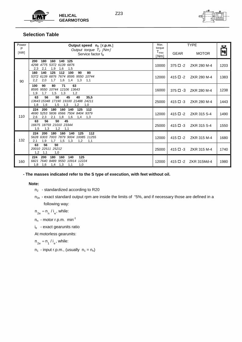
HELICAL GEARMOTORS
Selection Table
Power P
[kW]
Output speed n2 [r.p.m.] Output torque T2 [Nm]
Service factor fB
Max. torque Tmax [Nm]
TYPE
GEAR MOTOR
200 180 160 140 125 4298 4775 5372 6139 6876 2,3 2,1 1,9 1,6 1,5
10000
375 -2 ZKR 280 M-4
1203
90
160 140 125 112 100 90 80 5372 6139 6876 7674 8595 9550 10744 2,2 2,0 1,7 1,6 1,4 1,3 1,1
12000
415 -2 ZKR 280 M-4
1383
100 90 80 71 63 8595 9550 10744 12106 13643 1,9 1,7 1,5 1,3 1,2
16000
375 -3 ZKR 280 M-4
1238
63 56 50 45 40 35,5 13643 15348 17190 19100 21488 24211 1,8 1,6 1,5 1,3 1,2 1,0
25000
415 -3 ZKR 280 M-4
1443
110
224 200 180 160 140 125 112 4690 5253 5836 6566 7504 8404 9379 2,6 2,3 2,1 1,8 1,6 1,4 1,3
12000
415 -2 ZKR 315 S-4
1490
63 56 50 45 16675 18759 21010 23344 1,5 1,3 1,2 1,1
25000
415 -3 ZKR 315 S-4
1550
132
224 200 180 160 140 125 112 5628 6303 7003 7879 9004 10085 11255 2,1 1,9 1,7 1,5 1,3 1,2 1,1
12000
415 -2 ZKR 315 M-4
1680
63 56 50 20010 22511 25212 1,2 1,1 1,0
25000
415 -3 ZKR 315 M-4
1740
160
224 200 180 160 140 125 6821 7640 8489 9550 10914 12224 1,8 1,6 1,4 1,3 1,1 1,0
12000
415 -2 ZKR 315Md-4
1980
- The masses indicated refer to the S type of execution, with feet without oil. Note:
n2 - standardized according to R20
n2e - exact standard output rpm are inside the limits of “5%, and if necessary those are defined in a
following way:
n n ie n e2= / , while:
nn - motor r.p.m. min-1
ie - exact gearunits ratio
At motorless gearunits:
n n ie e2 1= / , while:
n1 - input r.p.m., (usually n1 = nn)
Z23
HELICAL GEAR UNITS
Z24
n1
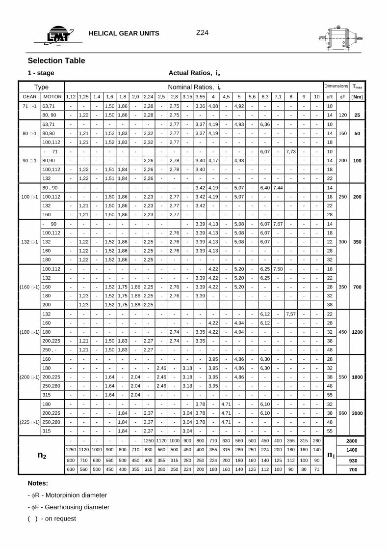
Selection Table 1 - stage Actual Ratios, ie
Type Nominal Ratios, in Dimensions Tmax
GEAR MOTOR 1,12 1,25 1,4 1,6 1,8 2,0 2,24 2,5 2,8 3,15 3,55 4 4,5 5 5,6 6,3 7,1 8 9 10 φR φF [Nm]
71 -1 63,71 - - - 1,50 1,86 - 2,28 - 2,75 - 3,36 4,08 - 4,92 - - - - - - 10
80, 90 - 1,22 - 1,50 1,86 - 2,28 - 2,75 - - - - - - - - - - - 14 120 25
63,71 - - - - - - - - 2,77 - 3,37 4,19 - 4,93 - 6,36 - - - - 10
80 -1 80,90 - 1,21 - 1,52 1,83 - 2,32 - 2,77 - 3,37 4,19 - - - - - - - - 14 160 50
100,112 - 1,21 - 1,52 1,83 - 2,32 - 2,77 - - - - - - - - - - - 18
- 71 - - - - - - - - - - - - - - 6,07 - 7,73 - - 10
90 -1 80,90 - - - - - - 2,26 - 2,78 - 3,40 4,17 - 4,93 - - - - - - 14 200 100
100,112 - 1,22 - 1,51 1,84 - 2,26 - 2,78 - 3,40 - - - - - - - - - 18
132 - 1,22 - 1,51 1,84 - 2,26 - - - - - - - - - - - - - 22
80 , 90 - - - - - - - - - - 3,42 4,19 - 5,07 - 6,40 7,44 - - - 14
100 -1 100,112 - - - 1,50 1,86 - 2,23 - 2,77 - 3,42 4,19 - 5,07 - - - - - - 18 250 200
132 - 1,21 - 1,50 1,86 - 2,23 - 2,77 - 3,42 - - - - - - - - - 22
160 - 1,21 - 1,50 1,86 - 2,23 - 2,77 - - - - - - - - - - - 28
- 90 - - - - - - - - - 3,39 4,13 - 5,08 - 6,07 7,67 - - - 14
100,112 - - - - - - - - 2,76 - 3,39 4,13 - 5,08 - 6,07 - - - - 18
132 -1 132 - 1,22 - 1,52 1,86 - 2,25 - 2,76 - 3,39 4,13 - 5,08 - 6,07 - - - - 22 300 350
160 - 1,22 - 1,52 1,86 - 2,25 - 2,76 - 3,39 4,13 - - - - - - - - 28
180 - 1,22 - 1,52 1,86 - 2,25 - - - - - - - - - - - - - 32
100,112 - - - - - - - - - - - 4,22 - 5,20 - 6,25 7,50 - - - 18
132 - - - - - - - - - - 3,39 4,22 - 5,20 - 6,25 - - - - 22
(160 -1) 160 - - - 1,52 1,75 1,86 2,25 - 2,76 - 3,39 4,22 - 5,20 - - - - - - 28 350 700
180 - 1,23 - 1,52 1,75 1,86 2,25 - 2,76 - 3,39 - - - - - - - - - 32
200 - 1,23 - 1,52 1,75 1,86 2,25 - - - - - - - - - - - - - 38
132 - - - - - - - - - - - - - - - 6,12 - 7,57 - - 22
160 - - - - - - - - - - 4,22 - 4,94 - 6,12 - - - - 28
(180 -1) 180 - - - - - - - - 2,74 - 3,35 4,22 - 4,94 - - - - - - 32 450 1200
200,225 - 1,21 - 1,50 1,83 - 2,27 - 2,74 - 3,35 - - - - - - - - - 38
250 , - - 1,21 - 1,50 1,83 - 2,27 - - - - - - - - - - - - - 48
160 - - - - - - - - - - - 3,95 - 4,86 - 6,30 - - - - 28
180 - - - - - - - 2,46 - 3,18 - 3,95 - 4,86 - 6,30 - - - - 32
(200 -1) 200,225 - - - 1,64 - 2,04 - 2,46 - 3,18 - 3,95 - 4,86 - - - - - - 38 550 1800
250,280 - - - 1,64 - 2,04 - 2,46 - 3,18 - 3,95 - - - - - - - - 48
315 - - - 1,64 - 2,04 - - - - - - - - - - - - - - 55
180 - - - - - - - - - - 3,78 - 4,71 - - 6,10 - - - - 32
200,225 - - - - 1,84 - 2,37 - - 3,04 3,78 - 4,71 - - 6,10 - - - - 38 660 3000
(225 -1) 250,280 - - - - 1,84 - 2,37 - - 3,04 3,78 - 4,71 - - - - - - - 48
315 - - - - 1,84 - 2,37 - - 3,04 - - - - - - - - - - 55
- - - - - - 1250 1120 1000 900 800 710 630 560 500 450 400 355 315 280 2800
1250 1120 1000 900 800 710 630 560 500 450 400 355 315 280 250 224 200 180 160 140 1400
800 710 630 560 500 450 400 355 315 280 250 224 200 180 160 140 125 112 100 90 930
630 560 500 450 400 355 315 280 250 224 200 180 160 140 125 112 100 90 80 71 700
Notes:
- φR - Motorpinion diameter
- φF - Gearhousing diameter
( ) - on request
n2
HELICAL GEAR UNITS
Z25
n1
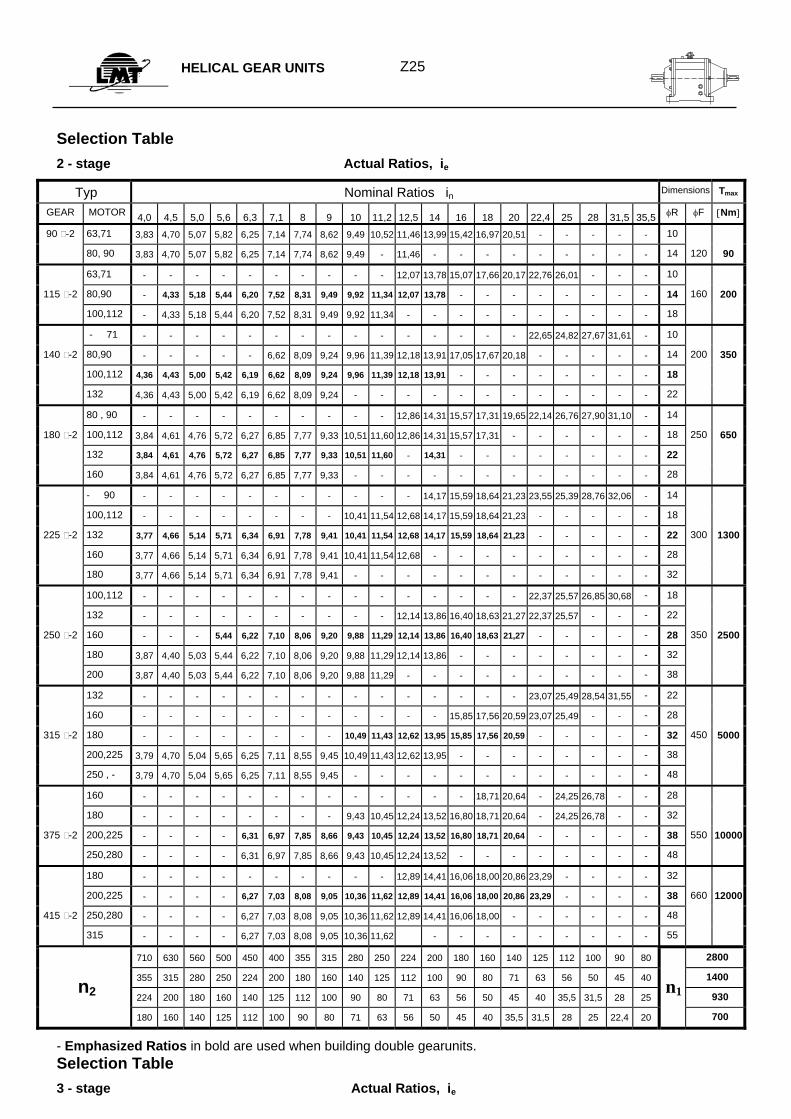
Selection Table 2 - stage Actual Ratios, ie
Typ Nominal Ratios in Dimensions Tmax
GEAR MOTOR 4,0 4,5 5,0 5,6 6,3 7,1 8 9 10 11,2 12,5 14 16 18 20 22,4 25 28 31,5 35,5 φR φF [Nm]
90 -2 63,71 3,83 4,70 5,07 5,82 6,25 7,14 7,74 8,62 9,49 10,52 11,46 13,99 15,42 16,97 20,51 - - - - - 10
80, 90 3,83 4,70 5,07 5,82 6,25 7,14 7,74 8,62 9,49 - 11,46 - - - - - - - - - 14 120 90
63,71 - - - - - - - - - - 12,07 13,78 15,07 17,66 20,17 22,76 26,01 - - - 10
115 -2 80,90 - 4,33 5,18 5,44 6,20 7,52 8,31 9,49 9,92 11,34 12,07 13,78 - - - - - - - - 14 160 200
100,112 - 4,33 5,18 5,44 6,20 7,52 8,31 9,49 9,92 11,34 - - - - - - - - - - 18
- 71 - - - - - - - - - - - - - - - 22,65 24,82 27,67 31,61 - 10
140 -2 80,90 - - - - - 6,62 8,09 9,24 9,96 11,39 12,18 13,91 17,05 17,67 20,18 - - - - - 14 200 350
100,112 4,36 4,43 5,00 5,42 6,19 6,62 8,09 9,24 9,96 11,39 12,18 13,91 - - - - - - - - 18
132 4,36 4,43 5,00 5,42 6,19 6,62 8,09 9,24 - - - - - - - - - - - - 22
80 , 90 - - - - - - - - - - 12,86 14,31 15,57 17,31 19,65 22,14 26,76 27,90 31,10 - 14
180 -2 100,112 3,84 4,61 4,76 5,72 6,27 6,85 7,77 9,33 10,51 11,60 12,86 14,31 15,57 17,31 - - - - - - 18 250 650
132 3,84 4,61 4,76 5,72 6,27 6,85 7,77 9,33 10,51 11,60 - 14,31 - - - - - - - - 22
160 3,84 4,61 4,76 5,72 6,27 6,85 7,77 9,33 - - - - - - - - - - - - 28
- 90 - - - - - - - - - - - 14,17 15,59 18,64 21,23 23,55 25,39 28,76 32,06 - 14
100,112 - - - - - - - - 10,41 11,54 12,68 14,17 15,59 18,64 21,23 - - - - - 18
225 -2 132 3,77 4,66 5,14 5,71 6,34 6,91 7,78 9,41 10,41 11,54 12,68 14,17 15,59 18,64 21,23 - - - - - 22 300 1300
160 3,77 4,66 5,14 5,71 6,34 6,91 7,78 9,41 10,41 11,54 12,68 - - - - - - - - - 28
180 3,77 4,66 5,14 5,71 6,34 6,91 7,78 9,41 - - - - - - - - - - - - 32
100,112 - - - - - - - - - - - - - - - 22,37 25,57 26,85 30,68 - 18
132 - - - - - - - - - - 12,14 13,86 16,40 18,63 21,27 22,37 25,57 - - - 22
250 -2 160 - - - 5,44 6,22 7,10 8,06 9,20 9,88 11,29 12,14 13,86 16,40 18,63 21,27 - - - - - 28 350 2500
180 3,87 4,40 5,03 5,44 6,22 7,10 8,06 9,20 9,88 11,29 12,14 13,86 - - - - - - - - 32
200 3,87 4,40 5,03 5,44 6,22 7,10 8,06 9,20 9,88 11,29 - - - - - - - - - - 38
132 - - - - - - - - - - - - - - - 23,07 25,49 28,54 31,55 - 22
160 - - - - - - - - - - - - 15,85 17,56 20,59 23,07 25,49 - - - 28
315 -2 180 - - - - - - - - 10,49 11,43 12,62 13,95 15,85 17,56 20,59 - - - - - 32 450 5000
200,225 3,79 4,70 5,04 5,65 6,25 7,11 8,55 9,45 10,49 11,43 12,62 13,95 - - - - - - - - 38
250 , - 3,79 4,70 5,04 5,65 6,25 7,11 8,55 9,45 - - - - - - - - - - - - 48
160 - - - - - - - - - - - - - 18,71 20,64 - 24,25 26,78 - - 28
180 - - - - - - - - 9,43 10,45 12,24 13,52 16,80 18,71 20,64 - 24,25 26,78 - - 32
375 -2 200,225 - - - - 6,31 6,97 7,85 8,66 9,43 10,45 12,24 13,52 16,80 18,71 20,64 - - - - - 38 550 10000
250,280 - - - - 6,31 6,97 7,85 8,66 9,43 10,45 12,24 13,52 - - - - - - - - 48
180 - - - - - - - - - - 12,89 14,41 16,06 18,00 20,86 23,29 - - - - 32
200,225 - - - - 6,27 7,03 8,08 9,05 10,36 11,62 12,89 14,41 16,06 18,00 20,86 23,29 - - - - 38 660 12000
415 -2 250,280 - - - - 6,27 7,03 8,08 9,05 10,36 11,62 12,89 14,41 16,06 18,00 - - - - - - 48
315 - - - - 6,27 7,03 8,08 9,05 10,36 11,62 - - - - - - - - - 55
710 630 560 500 450 400 355 315 280 250 224 200 180 160 140 125 112 100 90 80 2800
355 315 280 250 224 200 180 160 140 125 112 100 90 80 71 63 56 50 45 40 1400
224 200 180 160 140 125 112 100 90 80 71 63 56 50 45 40 35,5 31,5 28 25 930
180 160 140 125 112 100 90 80 71 63 56 50 45 40 35,5 31,5 28 25 22,4 20 700
- Emphasized Ratios in bold are used when building double gearunits. Selection Table 3 - stage Actual Ratios, ie
n2
HELICAL GEAR UNITS
Z26
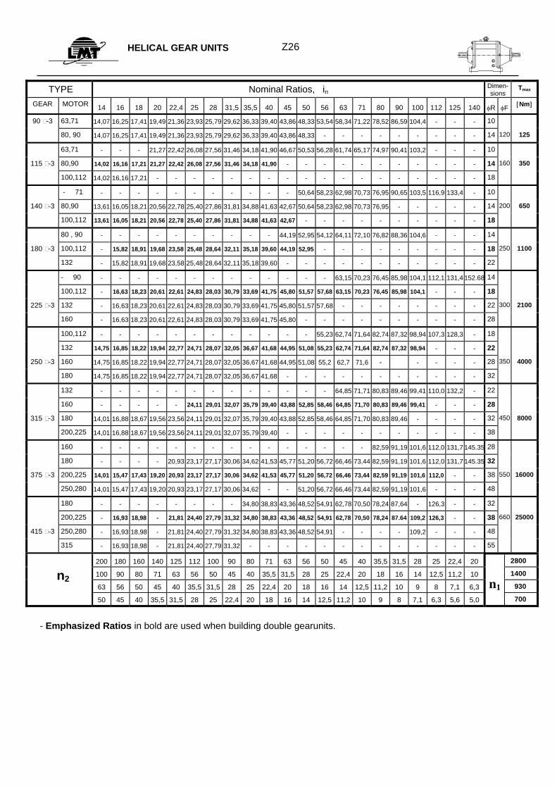
TYPE Nominal Ratios, in Dimen-sions
Tmax
GEAR MOTOR 14 16 18 20 22,4 25 28 31,5 35,5 40 45 50 56 63 71 80 90 100 112 125 140 φR φF [Nm]
90 -3 63,71 14,07 16,25 17,41 19,49 21,36 23,93 25,79 29,62 36,33 39,40 43,86 48,33 53,54 58,34 71,22 78,52 86,59 104,4 - - - 10
80, 90 14,07 16,25 17,41 19,49 21,36 23,93 25,79 29,62 36,33 39,40 43,86 48,33 - - - - - - - - - 14 120 125
63,71 - - - 21,27 22,42 26,08 27,56 31,46 34,18 41,90 46,67 50,53 56,28 61,74 65,17 74,97 90,41 103,2 - - - 10
115 -3 80,90 14,02 16,16 17,21 21,27 22,42 26,08 27,56 31,46 34,18 41,90 - - - - - - - - - - - 14 160 350
100,112 14,02 16,16 17,21 - - - - - - - - - - - - - - - - - - 18
- 71 - - - - - - - - - - - 50,64 58,23 62,98 70,73 76,95 90,65 103,5 116,9 133,4 - 10
140 -3 80,90 13,61 16,05 18,21 20,56 22,78 25,40 27,86 31,81 34,88 41,63 42,67 50,64 58,23 62,98 70,73 76,95 - - - - - 14 200 650
100,112 13,61 16,05 18,21 20,56 22,78 25,40 27,86 31,81 34,88 41,63 42,67 - - - - - - - - - - 18
80 , 90 - - - - - - - - - - 44,19 52,95 54,12 64,11 72,10 76,82 88,36 104,6 - - - 14
180 -3 100,112 - 15,82 18,91 19,68 23,58 25,48 28,64 32,11 35,18 39,60 44,19 52,95 - - - - - - - - - 18 250 1100
132 - 15,82 18,91 19,68 23,58 25,48 28,64 32,11 35,18 39,60 - - - - - - - - - - - 22
- 90 - - - - - - - - - - - - - 63,15 70,23 76,45 85,98 104,1 112,1 131,4 152.68 14
100,112 - 16,63 18,23 20,61 22,61 24,83 28,03 30,79 33,69 41,75 45,80 51,57 57,68 63,15 70,23 76,45 85,98 104,1 - - - 18
225 -3 132 - 16,63 18,23 20,61 22,61 24,83 28,03 30,79 33,69 41,75 45,80 51,57 57,68 - - - - - - - - 22 300 2100
160 - 16,63 18,23 20,61 22,61 24,83 28,03 30,79 33,69 41,75 45,80 - - - - - - - - - - 28
100,112 - - - - - - - - - - - - 55,23 62,74 71,64 82,74 87,32 98,94 107,3 128,3 - 18
132 14,75 16,85 18,22 19,94 22,77 24,71 28,07 32,05 36,67 41,68 44,95 51,08 55,23 62,74 71,64 82,74 87,32 98,94 - - - 22
250 -3 160 14,75 16,85 18,22 19,94 22,77 24,71 28,07 32,05 36,67 41,68 44,95 51,08 55,2 62,7 71,6 - - - - - 28 350 4000
180 14,75 16,85 18,22 19,94 22,77 24,71 28,07 32,05 36,67 41,68 - - - - - - - - - - - 32
132 - - - - - - - - - - - - - 64,85 71,71 80,83 89,46 99,41 110,0 132,2 - 22
160 - - - - - 24,11 29,01 32,07 35,79 39,40 43,88 52,85 58,46 64,85 71,70 80,83 89,46 99,41 - - - 28
315 -3 180 14,01 16,88 18,67 19,56 23,56 24,11 29,01 32,07 35,79 39,40 43,88 52,85 58,46 64,85 71,70 80,83 89,46 - - - - 32 450 8000
200,225 14,01 16,88 18,67 19,56 23,56 24,11 29,01 32,07 35,79 39,40 - - - - - - - - - - - 38
160 - - - - - - - - - - - - - - - 82,59 91,19 101,6 112,0 131,7 145.35 28
180 - - - - 20,93 23,17 27,17 30,06 34,62 41,53 45,77 51,20 56,72 66,46 73,44 82,59 91,19 101,6 112,0 131,7 145.35 32
375 -3 200,225 14,01 15,47 17,43 19,20 20,93 23,17 27,17 30,06 34,62 41,53 45,77 51,20 56,72 66,46 73,44 82,59 91,19 101,6 112,0 - - 38 550 16000
250,280 14,01 15,47 17,43 19,20 20,93 23,17 27,17 30,06 34,62 - - 51,20 56,72 66,46 73,44 82,59 91,19 101,6 - - - 48
180 - - - - - - - - 34,80 38,83 43,36 48,52 54,91 62,78 70,50 78,24 87,64 - 126,3 - - 32
200,225 - 16,93 18,98 - 21,81 24,40 27,79 31,32 34,80 38,83 43,36 48,52 54,91 62,78 70,50 78,24 87.64 109,2 126,3 - - 38 660 25000
415 -3 250,280 - 16,93 18,98 - 21,81 24,40 27,79 31,32 34,80 38,83 43,36 48,52 54,91 - - - - 109,2 - - - 48
315 - 16,93 18,98 - 21,81 24,40 27,79 31,32 - - - - - - - - - - - - - 55
200 180 160 140 125 112 100 90 80 71 63 56 50 45 40 35,5 31,5 28 25 22,4 20 2800
100 90 80 71 63 56 50 45 40 35,5 31,5 28 25 22,4 20 18 16 14 12,5 11,2 10 1400
63 56 50 45 40 35,5 31,5 28 25 22,4 20 18 16 14 12,5 11,2 10 9 8 7,1 6,3 930
50 45 40 35,5 31,5 28 25 22,4 20 18 16 14 12,5 11,2 10 9 8 7,1 6,3 5,6 5,0 700
- Emphasized Ratios in bold are used when building double gearunits.
n2 n1
DOUBLE HELICAL GEAR UNITS
Z27
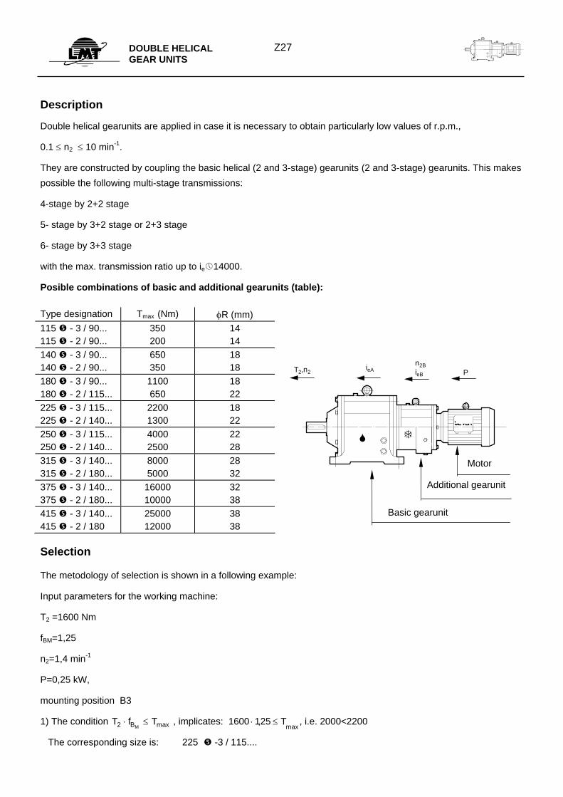
Description
Double helical gearunits are applied in case it is necessary to obtain particularly low values of r.p.m.,
0.1 ≤ n2 ≤ 10 min-1.
They are constructed by coupling the basic helical (2 and 3-stage) gearunits (2 and 3-stage) gearunits. This makes possible the following multi-stage transmissions:
4-stage by 2+2 stage
5- stage by 3+2 stage or 2+3 stage
6- stage by 3+3 stage
with the max. transmission ratio up to ie 14000.
Posible combinations of basic and additional gearunits (table): Type designation Tmax (Nm) φR (mm) 115 - 3 / 90... 115 - 2 / 90...
350 200
14 14
140 - 3 / 90... 140 - 2 / 90...
650 350
18 18
180 - 3 / 90... 180 - 2 / 115...
1100 650
18 22
225 - 3 / 115... 225 - 2 / 140...
2200 1300
18 22
250 - 3 / 115... 250 - 2 / 140...
4000 2500
22 28
315 - 3 / 140... 315 - 2 / 180...
8000 5000
28 32
375 - 3 / 140... 375 - 2 / 180...
16000 10000
32 38
415 - 3 / 140... 415 - 2 / 180
25000 12000
38 38
Selection
The metodology of selection is shown in a following example:
Input parameters for the working machine:
T2 =1600 Nm
fBM=1,25
n2=1,4 min-1
P=0,25 kW,
mounting position B3
1) The condition T f TBM2 ⋅ ≤ max , implicates: 1600 125⋅ ≤,max
T , i.e. 2000<2200
The corresponding size is: 225 -3 / 115....
PieAT2,n2
n2BieB
Motor
Additional gearunit
Basic gearunit
DOUBLE HELICAL GEAR UNITS
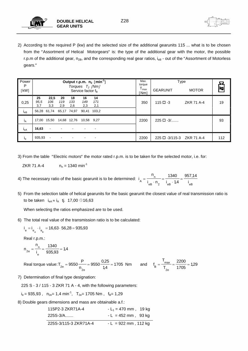
Z28
2) According to the required P (kw) and the selected size of the additional gearunits 115 ... what is to be chosen from the ″Assortment of Helical Motorgears″ is: the type of the additional gear with the motor, the possible r.p.m of the additional gear, n2B, and the corresponding real gear ratios, ieB - out of the ″Assortment of Motorless gears.″
Power P
[kW]
Output r.p.m. n2 [min-1] Torques T2 [Nm]
Service factor fB
Max. torque Tmax [Nm]
Type
GEARUNIT MOTOR
0,25
25 22,5 20 18 16 14 95,5 106 119 133 149 171 3,7 3,3 2,9 2,6 2,3 2,1
350
115 -3 ZKR 71 A-4
19
ieB 56,28 61,74 65,17 74,97 90,41 103,2
iA 17,00 15,50 14,68 12,76 10,58 9,27 2200 225 -3/....... 93
ieA 16,63 - - - - -
ie 935,93 - - - - - 2200 225 -3/115-3 ZKR 71 A-4 112
3) From the table ″Electric motors″ the motor rated r.p.m. is to be taken for the selected motor, i.e. for:
ZKR 71 A-4 nn = 1340 min-1
4) The necessary ratio of the basic gearunit is to be determined: in
i n i iAn
eB eB eB
=⋅
=⋅
=2
134014
957 14,
,
5) From the selection table of helical gearunits for the basic gearunit the closest value of real transmission ratio is to be taken ieA ≈ iA tj. 17,00 16,63
When selecting the ratios emphasized are to be used.
6) The total real value of the transmission ratio is to be calculated:
i i ie e e
A B= ⋅ = ⋅ =16 63 56 28 935 93, , ,
Real r.p.m.:
nn
ien
e2
1340935 93
14= = =,
,
Real torque value:TP
nNm
ee
22
9550 95500 2514
1705= = =,,
and fT
TBe
= = =max ,2
22001705
129
7) Determination of final type designation:
225 S - 3 / 115 - 3 ZKR 71 A - 4, with the following parameters:
ie = 935,93 , n2e= 1,4 min-1, T2e= 1705 Nm , fB= 1,29
8) Double gears dimensions and mass are obtainable a.f.: 115P2-3 ZKR71A-4 - L1 = 470 mm , 19 kg 225S-3/A....... - L = 452 mm , 93 kg
225S-3/115-3 ZKR71A-4 - L = 922 mm , 112 kg

DOUBLE HELICAL GEAR UNITS
Z29
Notes:
Selection tables to be prepared
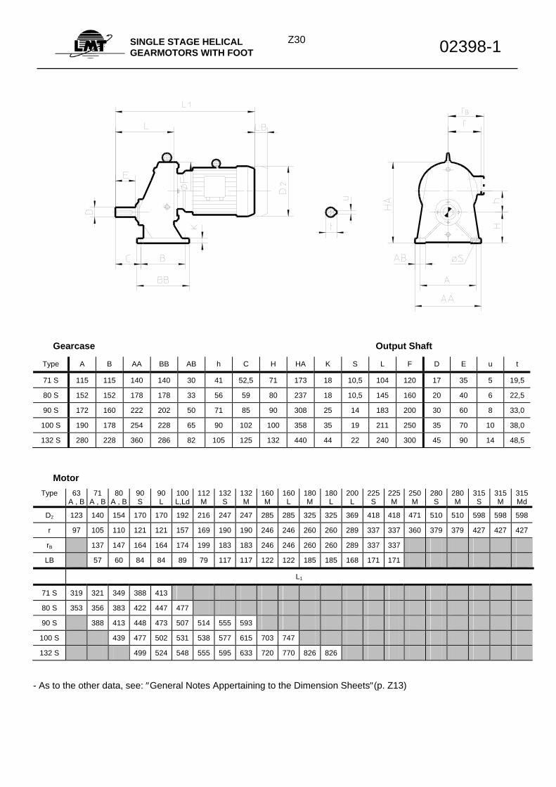
Z30SINGLE STAGE HELICAL GEARMOTORS WITH FOOT 02398-1
Gearcase Output Shaft
Type A B AA BB AB h C H HA K S L F D E u t
71 S 115 115 140 140 30 41 52,5 71 173 18 10,5 104 120 17 35 5 19,5
80 S 152 152 178 178 33 56 59 80 237 18 10,5 145 160 20 40 6 22,5
90 S 172 160 222 202 50 71 85 90 308 25 14 183 200 30 60 8 33,0
100 S 190 178 254 228 65 90 102 100 358 35 19 211 250 35 70 10 38,0
132 S 280 228 360 286 82 105 125 132 440 44 22 240 300 45 90 14 48,5
Motor Type 63
A , B 71
A , B 80
A , B 90 S
90 L
100 L,Ld
112M
132 S
132 M
160 M
160 L
180 M
180 L
200 L
225 S
225 M
250 M
280 S
280 M
315 S
315 M
315 Md
D2 123 140 154 170 170 192 216 247 247 285 285 325 325 369 418 418 471 510 510 598 598 598
r 97 105 110 121 121 157 169 190 190 246 246 260 260 289 337 337 360 379 379 427 427 427
rB 137 147 164 164 174 199 183 183 246 246 260 260 289 337 337
LB 57 60 84 84 89 79 117 117 122 122 185 185 168 171 171
L1
71 S 319 321 349 388 413
80 S 353 356 383 422 447 477
90 S 388 413 448 473 507 514 555 593
100 S 439 477 502 531 538 577 615 703 747
132 S 499 524 548 555 595 633 720 770 826 826
- As to the other data, see: ″General Notes Appertaining to the Dimension Sheets″(p. Z13)
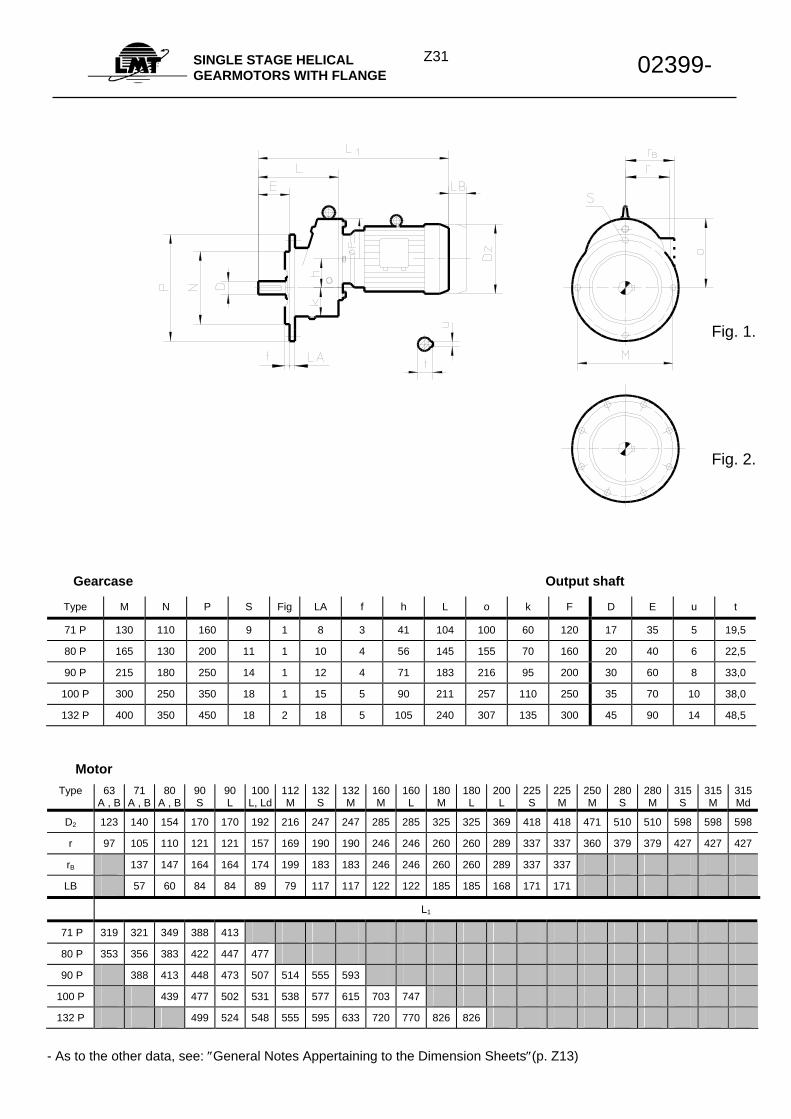
Z31SINGLE STAGE HELICAL
GEARMOTORS WITH FLANGE 02399-
Gearcase Output shaft Type M N P S Fig LA f h L o k F D E u t
71 P 130 110 160 9 1 8 3 41 104 100 60 120 17 35 5 19,5
80 P 165 130 200 11 1 10 4 56 145 155 70 160 20 40 6 22,5
90 P 215 180 250 14 1 12 4 71 183 216 95 200 30 60 8 33,0
100 P 300 250 350 18 1 15 5 90 211 257 110 250 35 70 10 38,0
132 P 400 350 450 18 2 18 5 105 240 307 135 300 45 90 14 48,5
Motor Type 63
A , B 71
A , B 80
A , B 90 S
90 L
100 L, Ld
112M
132 S
132 M
160 M
160 L
180 M
180 L
200 L
225 S
225 M
250 M
280 S
280 M
315 S
315 M
315 Md
D2 123 140 154 170 170 192 216 247 247 285 285 325 325 369 418 418 471 510 510 598 598 598
r 97 105 110 121 121 157 169 190 190 246 246 260 260 289 337 337 360 379 379 427 427 427
rB 137 147 164 164 174 199 183 183 246 246 260 260 289 337 337
LB 57 60 84 84 89 79 117 117 122 122 185 185 168 171 171
L1
71 P 319 321 349 388 413
80 P 353 356 383 422 447 477
90 P 388 413 448 473 507 514 555 593
100 P 439 477 502 531 538 577 615 703 747
132 P 499 524 548 555 595 633 720 770 826 826
- As to the other data, see: ″General Notes Appertaining to the Dimension Sheets″(p. Z13)
Fig. 1.
Fig. 2.
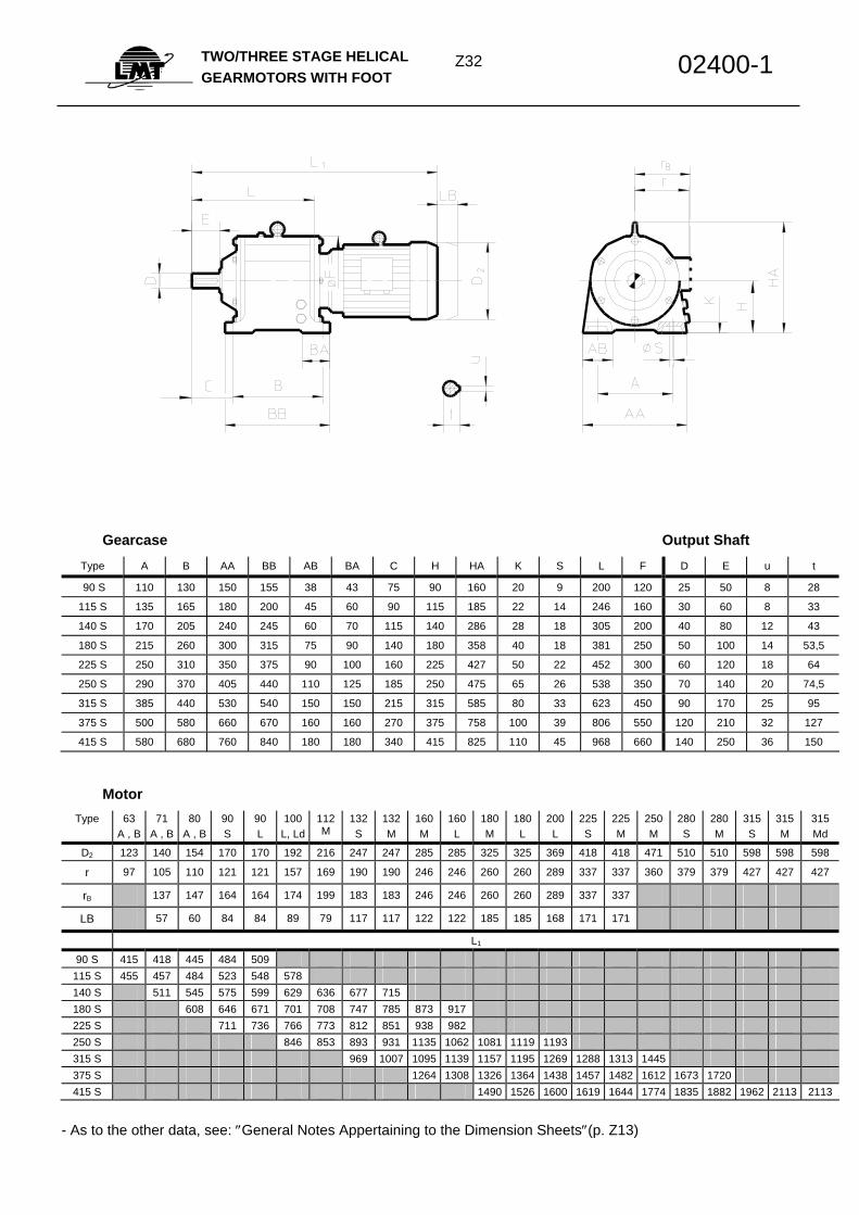
Z32TWO/THREE STAGE HELICAL
GEARMOTORS WITH FOOT 02400-1
Gearcase Output Shaft Type A B AA BB AB BA C H HA K S L F D E u t
90 S 110 130 150 155 38 43 75 90 160 20 9 200 120 25 50 8 28
115 S 135 165 180 200 45 60 90 115 185 22 14 246 160 30 60 8 33
140 S 170 205 240 245 60 70 115 140 286 28 18 305 200 40 80 12 43
180 S 215 260 300 315 75 90 140 180 358 40 18 381 250 50 100 14 53,5
225 S 250 310 350 375 90 100 160 225 427 50 22 452 300 60 120 18 64
250 S 290 370 405 440 110 125 185 250 475 65 26 538 350 70 140 20 74,5
315 S 385 440 530 540 150 150 215 315 585 80 33 623 450 90 170 25 95
375 S 500 580 660 670 160 160 270 375 758 100 39 806 550 120 210 32 127
415 S 580 680 760 840 180 180 340 415 825 110 45 968 660 140 250 36 150
Motor Type 63
A , B 71
A , B 80
A , B 90 S
90 L
100 L, Ld
112M
132 S
132 M
160 M
160 L
180 M
180 L
200 L
225 S
225 M
250 M
280 S
280 M
315 S
315 M
315 Md
D2 123 140 154 170 170 192 216 247 247 285 285 325 325 369 418 418 471 510 510 598 598 598
r 97 105 110 121 121 157 169 190 190 246 246 260 260 289 337 337 360 379 379 427 427 427
rB 137 147 164 164 174 199 183 183 246 246 260 260 289 337 337
LB 57 60 84 84 89 79 117 117 122 122 185 185 168 171 171
L1
90 S 415 418 445 484 509 115 S 455 457 484 523 548 578 140 S 511 545 575 599 629 636 677 715 180 S 608 646 671 701 708 747 785 873 917 225 S 711 736 766 773 812 851 938 982 250 S 846 853 893 931 1135 1062 1081 1119 1193 315 S 969 1007 1095 1139 1157 1195 1269 1288 1313 1445 375 S 1264 1308 1326 1364 1438 1457 1482 1612 1673 1720 415 S 1490 1526 1600 1619 1644 1774 1835 1882 1962 2113 2113
- As to the other data, see: ″General Notes Appertaining to the Dimension Sheets″(p. Z13)
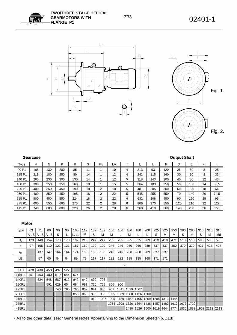
Z33
TWO/THREE STAGE HELICAL GEARMOTORS WITH FLANGE P1 02401-1
Gearcase Output Shaft Type M N P R S Fig LA f L k F D E u t
90 P1 165 130 200 85 11 1 10 4 213 93 120 25 50 8 28 115 P1 215 180 250 80 14 1 12 4 242 115 160 30 60 8 33 140 P1 265 230 300 130 14 1 12 5 318 143 200 40 80 12 43 180 P1 300 250 350 160 18 1 15 5 364 183 250 50 100 14 53,5 225 P1 400 350 450 190 18 2 18 5 481 205 300 60 120 18 64 250 P1 400 350 450 195 18 2 22 5 545 255 350 70 140 20 74,5 315 P1 500 450 550 224 18 2 22 6 632 308 450 90 160 25 95 375 P1 600 550 660 275 22 2 28 6 806 370 550 120 210 32 127 415 P1 740 680 800 320 26 2 28 6 968 410 660 140 250 36 150
Motor Type 63
A , B 71
A , B 80
A , B 90 S
90 L
100 L, Ld
112M
132 S
132M
160M
160L
180M
180L
200L
225S
225 M
250 M
280 S
280 M
315S
315M
315 Md
D2 123 140 154 170 170 192 216 247 247 285 285 325 325 369 418 418 471 510 510 598 598 598
r 97 105 110 121 121 157 169 190 190 246 246 260 260 289 337 337 360 379 379 427 427 427
rB 137 147 164 164 174 199 183 183 246 246 260 260 289 337 337
LB 57 60 84 84 89 79 117 117 122 122 185 185 168 171 171
L1
90P1 428 430 458 497 522 115P1 451 453 480 519 544 574 140P1 524 548 587 612 642 649 690 728 180P1 591 629 654 684 691 730 768 856 900 225P1 740 765 795 802 841 880 967 1011 1029 1067 250P1 853 860 900 938 1025 1069 1088 1126 1200 315P1 969 1007 1095 1139 1157 1195 1269 1288 1313 1445 375P1 1264 1308 1326 1364 1438 1457 1482 1612 1673 1720 415P1 1490 1526 1600 1619 1644 1774 1835 1882 1962 2113 2113
- As to the other data, see: ″General Notes Appertaining to the Dimension Sheets″(p. Z13)
Fig. 1.
Fig. 2.
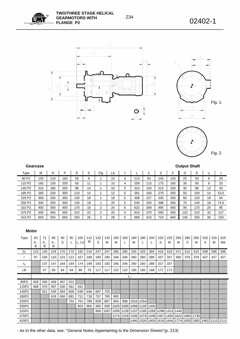
Z34
TWO/THREE STAGE HELICAL GEARMOTORS WITH FLANGE P2 02402-1
Gearcase Output Shaft
Type M N P R S Fig LA f L k Z F D E u t
90 P2 130 110 160 55 9 1 10 4 213 93 145 120 25 50 8 28 115 P2 165 130 200 65 11 1 10 4 259 115 175 160 30 60 8 33 140 P2 215 180 250 86 14 1 10 5 315 143 215 200 40 80 12 43 180 P2 265 230 300 110 14 1 12 5 391 183 275 250 50 100 14 53,5 225 P2 300 250 350 130 18 1 18 5 468 227 330 300 60 120 18 64 250 P2 300 250 350 135 18 1 20 5 545 255 388 350 70 140 18 74,5 315 P2 400 350 450 170 18 2 20 6 623 308 495 450 90 170 25 95 375 P2 500 450 550 210 22 2 25 6 816 370 590 550 120 210 32 127 415 P2 600 550 660 250 26 2 28 6 968 410 710 660 140 250 36 150
Motor Type 63
A , B
71 A , B
80 A , B
90 S
90 L
100 L, Ld
112M
132S
132M
160M
160L
180M
180L
200L
225S
225 M
250 M
280 S
280M
315S
315M
315 Md
D2 123 140 154 170 170 192 216 247 247 285 285 325 325 369 418 418 471 510 510 598 598 598
r 97 105 110 121 121 157 169 190 190 246 246 260 260 289 337 337 360 379 379 427 427 427
rB 137 147 164 164 174 199 183 183 246 246 260 260 289 337 337
LB 57 60 84 84 89 79 117 117 122 122 185 185 168 171 171
L1
90P2 428 430 458 497 522 115P2 468 470 497 536 561 591 140P2 521 545 584 609 639 646 687 725 180P2 618 656 681 711 718 757 795 883 225P2 752 701 789 828 867 954 998 1016 1054 250P2 853 860 900 938 1025 1069 1088 1126 1200 315P2 969 1007 1095 1139 1157 1195 1269 1288 1313 1445 375P2 1274 1318 1336 1374 1448 1467 1492 1622 1683 1730 415P2 1490 1526 1600 1619 1644 1774 1835 1882 1962 2113 2113
- As to the other data, see: ″General Notes Appertaining to the Dimension Sheets″(p. Z13)
Fig. 2.
Fig. 1.
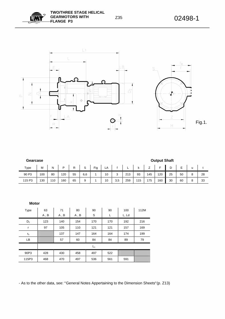
Z35
TWO/THREE STAGE HELICAL GEARMOTORS WITH FLANGE P3 02498-1
Gearcase Output Shaft Type M N P R S Fig LA f L k Z F D E u t
90 P3 100 80 120 55 6,6 1 10 3 213 93 145 120 25 50 8 28
115 P3 130 110 160 65 9 1 10 3,5 259 115 175 160 30 60 8 33
Motor Type 63
A , B 71
A , B 80
A , B 90 S
90 L
100 L, Ld
112M
D2 123 140 154 170 170 192 216
r 97 105 110 121 121 157 169
rb 137 147 164 164 174 199
LB 57 60 84 84 89 79
L1
90P3 428 430 458 497 522
115P3 468 470 497 536 561 591
- As to the other data, see: ″General Notes Appertaining to the Dimension Sheets″(p. Z13)
Fig.1.
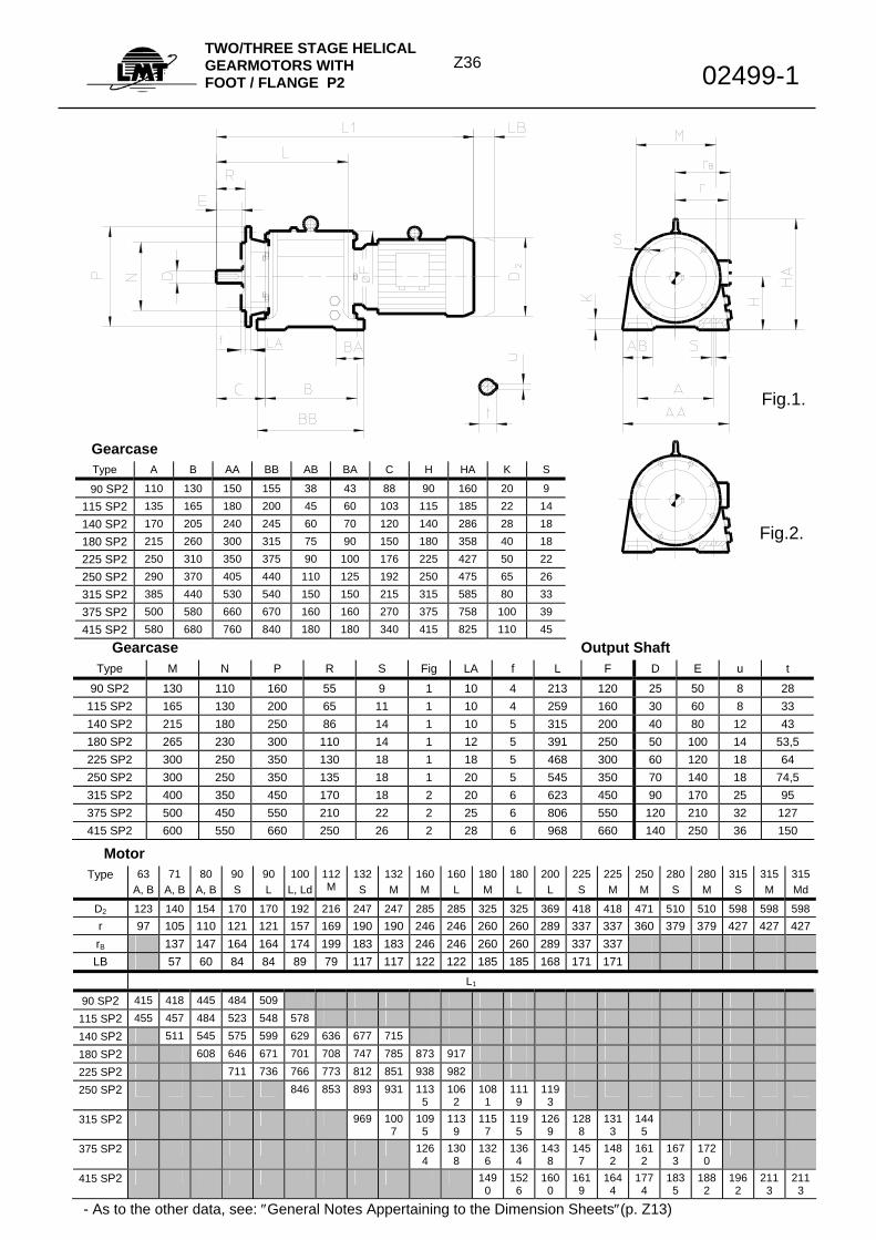
Z36
TWO/THREE STAGE HELICAL GEARMOTORS WITH FOOT / FLANGE P2 02499-1
Gearcase Output Shaft
Type M N P R S Fig LA f L F D E u t
90 SP2 130 110 160 55 9 1 10 4 213 120 25 50 8 28 115 SP2 165 130 200 65 11 1 10 4 259 160 30 60 8 33 140 SP2 215 180 250 86 14 1 10 5 315 200 40 80 12 43 180 SP2 265 230 300 110 14 1 12 5 391 250 50 100 14 53,5 225 SP2 300 250 350 130 18 1 18 5 468 300 60 120 18 64 250 SP2 300 250 350 135 18 1 20 5 545 350 70 140 18 74,5 315 SP2 400 350 450 170 18 2 20 6 623 450 90 170 25 95 375 SP2 500 450 550 210 22 2 25 6 806 550 120 210 32 127 415 SP2 600 550 660 250 26 2 28 6 968 660 140 250 36 150
Motor Type 63
A, B 71
A, B 80
A, B 90 S
90 L
100 L, Ld
112M
132 S
132 M
160 M
160 L
180 M
180 L
200 L
225 S
225 M
250 M
280 S
280 M
315 S
315 M
315 Md
D2 123 140 154 170 170 192 216 247 247 285 285 325 325 369 418 418 471 510 510 598 598 598 r 97 105 110 121 121 157 169 190 190 246 246 260 260 289 337 337 360 379 379 427 427 427rB 137 147 164 164 174 199 183 183 246 246 260 260 289 337 337 LB 57 60 84 84 89 79 117 117 122 122 185 185 168 171 171
L1
90 SP2 415 418 445 484 509
115 SP2 455 457 484 523 548 578
140 SP2 511 545 575 599 629 636 677 715
180 SP2 608 646 671 701 708 747 785 873 917
225 SP2 711 736 766 773 812 851 938 982
250 SP2 846 853 893 931 1135
1062
1081
1119
1193
315 SP2 969 1007
1095
1139
1157
1195
1269
1288
1313
1445
375 SP2 1264
1308
1326
1364
1438
1457
1482
1612
1673
1720
415 SP2 1490
1526
1600
1619
1644
1774
1835
1882
1962
2113
2113
- As to the other data, see: ″General Notes Appertaining to the Dimension Sheets″(p. Z13)
Gearcase Type A B AA BB AB BA C H HA K S
90 SP2 110 130 150 155 38 43 88 90 160 20 9 115 SP2 135 165 180 200 45 60 103 115 185 22 14 140 SP2 170 205 240 245 60 70 120 140 286 28 18 180 SP2 215 260 300 315 75 90 150 180 358 40 18 225 SP2 250 310 350 375 90 100 176 225 427 50 22 250 SP2 290 370 405 440 110 125 192 250 475 65 26 315 SP2 385 440 530 540 150 150 215 315 585 80 33 375 SP2 500 580 660 670 160 160 270 375 758 100 39 415 SP2 580 680 760 840 180 180 340 415 825 110 45
Fig.1.
Fig.2.
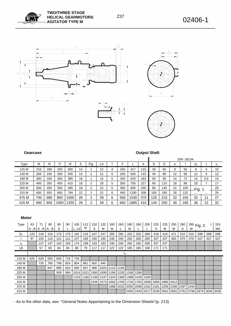
Z37
TWO/THREE STAGE HELICAL GEARMOTORS AGITATOR TYPE M 02406-1
Gearcase Output Shaft DIN 28134
Type M N P R S Fig. LA f F L k D E u l d2 t t1
115 M 215 180 250 260 14 1 12 4 160 417 115 30 65 8 50 8 4 10 140 M 265 230 300 345 14 1 12 5 200 530 143 40 80 12 58 12 5 12 180 M 300 250 350 385 18 1 15 5 250 620 183 50 95 14 72 14 5.5 14 225 M 400 350 450 410 18 2 18 5 300 700 227 60 110 18 88 18 7 17 250 M 500 450 550 495 18 2 22 5 350 845 255 80 140 22 105 22 9 20 315 M 600 550 660 794 22 2 22 6 450 1190 308 100 165 28 132 28 10 26 375 M 740 680 800 1000 26 2 28 6 550 1530 370 125 215 32 155 32 11 27 415 M 940 800 1000 1250 26 2 28 6 660 1885 410 140 250 36 185 36 12 32
Motor Type 63
A , B 71
A , B 80
A , B 90 S
90 L
100 L, Ld
112M
132 S
132 M
160 M
160 L
180 M
180 L
200 L
225 S
225 M
250 M
280 S
280 M
315 S
315 M
315 Md
D2 123 140 154 170 170 192 216 247 247 285 285 325 325 369 418 418 471 510 510 598 598 598 r 97 105 110 121 121 157 169 190 190 246 246 260 260 289 337 337 360 379 379 427 427 427 rB 137 147 164 164 174 199 183 183 246 246 260 260 289 337 337 LB 57 60 84 84 89 79 117 117 122 122 185 185 168 171 171
L1
115 M 625 628 655 694 719 749 140 M 735 760 799 824 854 861 902 940 180 M 847 885 910 940 947 986 1024 1112 1156 225 M 959 984 1014 1021 1060 1099 1186 1230 1248 1286 250 M 1153 1160 1199 1237 1324 1368 1388 1426 1500 315 M 1535 1573 1662 1706 1724 1762 1836 1855 1880 2012 375 M 1988 2032 2050 2088 2162 2181 2206 2336 2397 2444 415 M 2405 2443 2517 2536 2561 2691 2752 2799 2879 3030 3030
- As to the other data, see: ″General Notes Appertaining to the Dimension Sheets″(p. Z13)
Fig. 2.
Fig. 1.
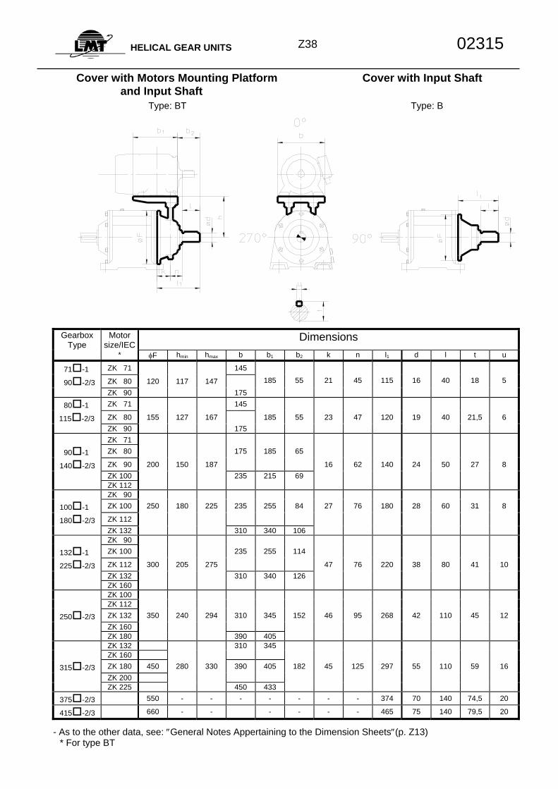
Z38HELICAL GEAR UNITS 02315
Cover with Motors Mounting Platform Cover with Input Shaft and Input Shaft Type: BT Type: B
Gearbox
Type Motor
size/IEC Dimensions
* φF hmin hmax b b1 b2 k n l1 d l t u
71 -1 ZK 71 145
90 -2/3 ZK 80 120 117 147 185 55 21 45 115 16 40 18 5 ZK 90 175
80 -1 ZK 71 145
115 -2/3 ZK 80 155 127 167 185 55 23 47 120 19 40 21,5 6 ZK 90 175 ZK 71
90 -1 ZK 80 175 185 65
140 -2/3 ZK 90 200 150 187 16 62 140 24 50 27 8 ZK 100 235 215 69 ZK 112 ZK 90
100 -1 ZK 100 250 180 225 235 255 84 27 76 180 28 60 31 8
180 -2/3 ZK 112
ZK 132 310 340 106 ZK 90
132 -1 ZK 100 235 255 114
225 -2/3 ZK 112 300 205 275 47 76 220 38 80 41 10 ZK 132 310 340 126 ZK 160 ZK 100 ZK 112
250 -2/3 ZK 132 350 240 294 310 345 152 46 95 268 42 110 45 12 ZK 160 ZK 180 390 405 ZK 132 310 345 ZK 160
315 -2/3 ZK 180 450 280 330 390 405 182 45 125 297 55 110 59 16 ZK 200 ZK 225 450 433
375 -2/3 550 - - - - - - - 374 70 140 74,5 20
415 -2/3 660 - - - - - - 465 75 140 79,5 20
- As to the other data, see: ″General Notes Appertaining to the Dimension Sheets″(p. Z13) * For type BT
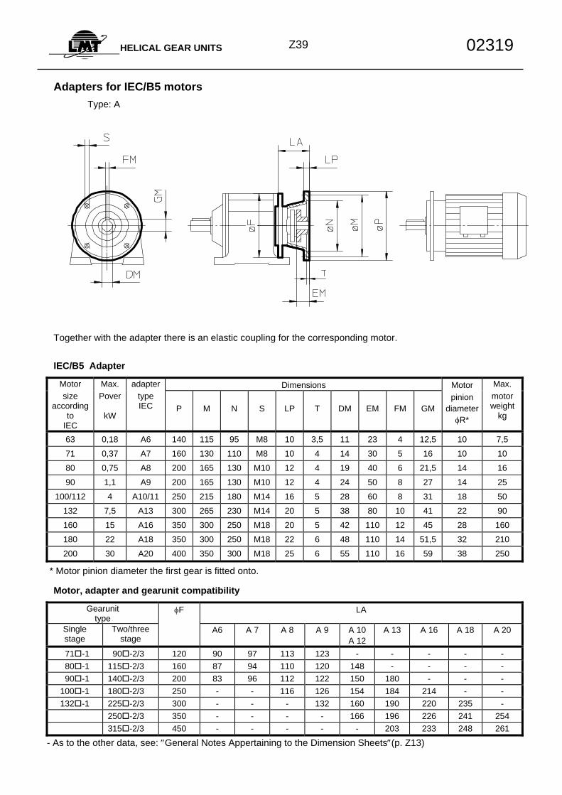
Z39HELICAL GEAR UNITS 02319
Adapters for IEC/B5 motors
Type: A
Together with the adapter there is an elastic coupling for the corresponding motor.
IEC/B5 Adapter Motor Max. adapter Dimensions Motor Max. size
according to
IEC
Pover
kW
type IEC P M N S LP T DM EM FM GM
pinion diameter
φR*
motor weight
kg
63 0,18 A6 140 115 95 M8 10 3,5 11 23 4 12,5 10 7,5
71 0,37 A7 160 130 110 M8 10 4 14 30 5 16 10 10
80 0,75 A8 200 165 130 M10 12 4 19 40 6 21,5 14 16
90 1,1 A9 200 165 130 M10 12 4 24 50 8 27 14 25
100/112 4 A10/11 250 215 180 M14 16 5 28 60 8 31 18 50
132 7,5 A13 300 265 230 M14 20 5 38 80 10 41 22 90
160 15 A16 350 300 250 M18 20 5 42 110 12 45 28 160
180 22 A18 350 300 250 M18 22 6 48 110 14 51,5 32 210
200 30 A20 400 350 300 M18 25 6 55 110 16 59 38 250
* Motor pinion diameter the first gear is fitted onto.
Motor, adapter and gearunit compatibility Gearunit
type φF LA
Single stage
Two/three stage
A6 A 7 A 8 A 9 A 10 A 12
A 13 A 16 A 18 A 20
71 -1 90 -2/3 120 90 97 113 123 - - - - - 80 -1 115 -2/3 160 87 94 110 120 148 - - - - 90 -1 140 -2/3 200 83 96 112 122 150 180 - - - 100 -1 180 -2/3 250 - - 116 126 154 184 214 - - 132 -1 225 -2/3 300 - - - 132 160 190 220 235 -
250 -2/3 350 - - - - 166 196 226 241 254 315 -2/3 450 - - - - - 203 233 248 261
- As to the other data, see: ″General Notes Appertaining to the Dimension Sheets″(p. Z13)
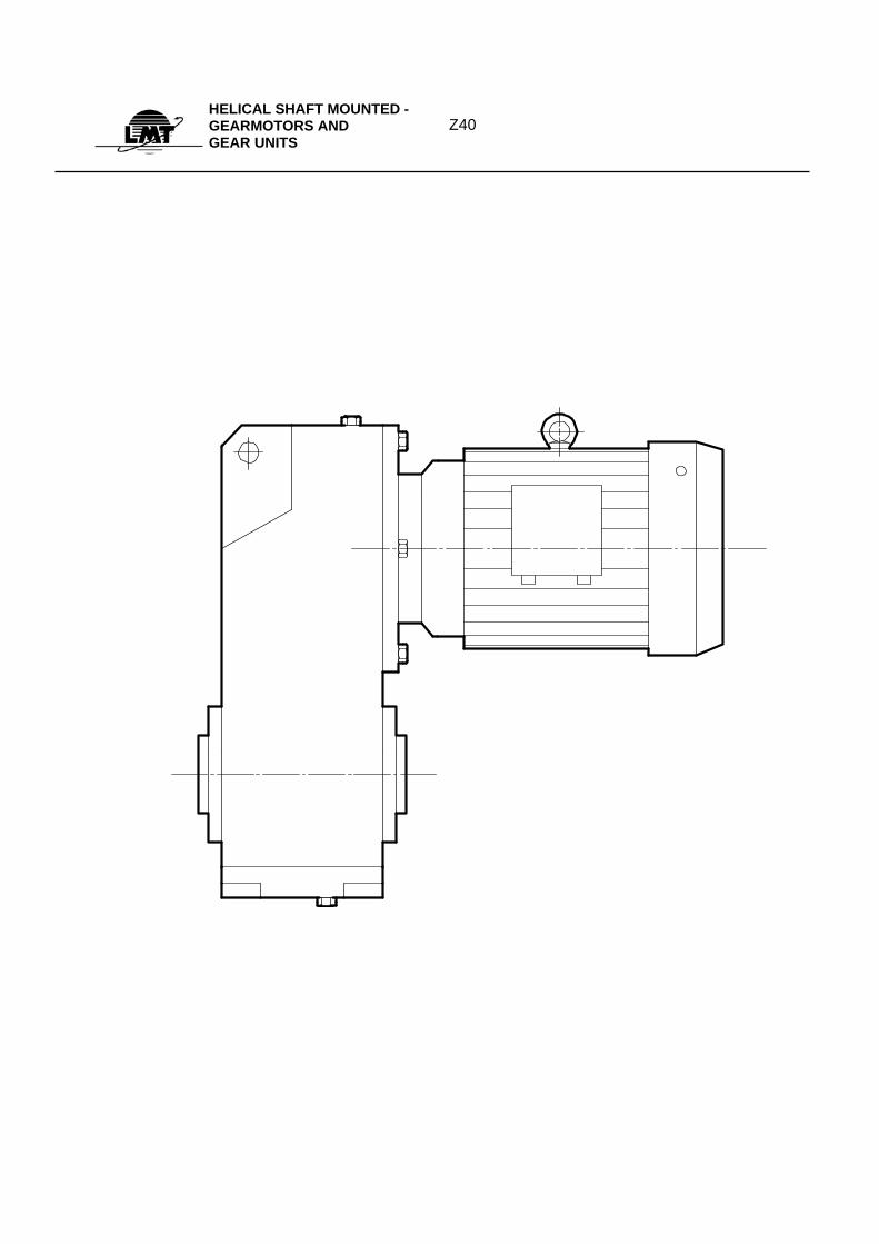
Z40HELICAL SHAFT MOUNTED - GEARMOTORS AND GEAR UNITS
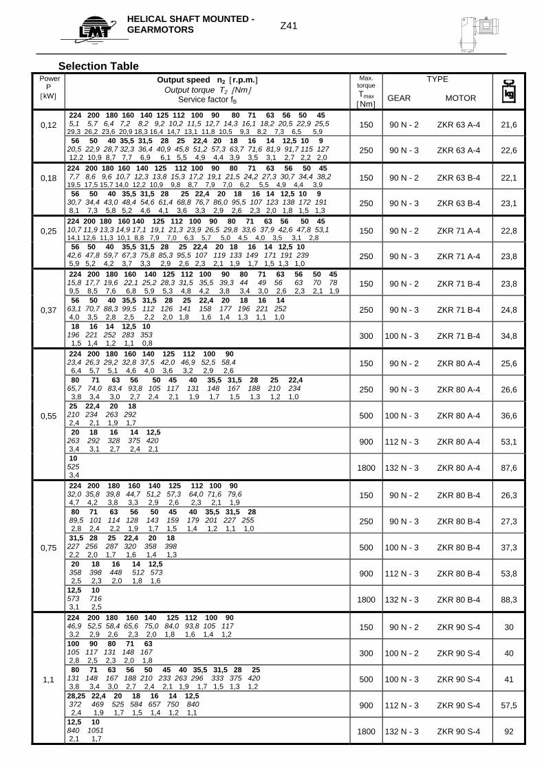
Z41 HELICAL SHAFT MOUNTED - GEARMOTORS
Selection Table Power
P [kW]
Output speed n2 [r.p.m.] Output torque T2 [Nm]
Service factor fB
Max. torque Tmax [Nm]
TYPE
GEAR MOTOR
0,12
224 200 180 160 140 125 112 100 90 80 71 63 56 50 45 5,1 5,7 6,4 7,2 8,2 9,2 10,2 11,5 12,7 14,3 16,1 18,2 20,5 22,9 25,5 29,3 26,2 23,6 20,9 18,3 16,4 14,7 13,1 11,8 10,5 9,3 8,2 7,3 6,5 5,9
150 90 N - 2 ZKR 63 A-4 21,6
56 50 40 35,5 31,5 28 25 22,4 20 18 16 14 12,5 10 9 20,5 22,9 28,7 32,3 36,4 40,9 45,8 51,2 57,3 63,7 71,6 81,9 91,7 115 127 12,2 10,9 8,7 7,7 6,9 6,1 5,5 4,9 4,4 3,9 3,5 3,1 2,7 2,2 2,0
250 90 N - 3 ZKR 63 A-4 22,6
0,18
224 200 180 160 140 125 112 100 90 80 71 63 56 50 45 7,7 8,6 9,6 10,7 12,3 13,8 15,3 17,2 19,1 21,5 24,2 27,3 30,7 34,4 38,2 19,5 17,5 15,7 14,0 12,2 10,9 9,8 8,7 7,9 7,0 6,2 5,5 4,9 4,4 3,9
150 90 N - 2 ZKR 63 B-4 22,1
56 50 40 35,5 31,5 28 25 22,4 20 18 16 14 12,5 10 9 30,7 34,4 43,0 48,4 54,6 61,4 68,8 76,7 86,0 95,5 107 123 138 172 191 8,1 7,3 5,8 5,2 4,6 4,1 3,6 3,3 2,9 2,6 2,3 2,0 1,8 1,5 1,3
250 90 N - 3 ZKR 63 B-4 23,1
0,25
224 200 180 160 140 125 112 100 90 80 71 63 56 50 45 10,7 11,9 13,3 14,9 17,1 19,1 21,3 23,9 26,5 29,8 33,6 37,9 42,6 47,8 53,1 14,1 12,6 11,3 10,1 8,8 7,9 7,0 6,3 5,7 5,0 4,5 4,0 3,5 3,1 2,8
150 90 N - 2 ZKR 71 A-4 22,8
56 50 40 35,5 31,5 28 25 22,4 20 18 16 14 12,5 10 42,6 47,8 59,7 67,3 75,8 85,3 95,5 107 119 133 149 171 191 239 5,9 5,2 4,2 3,7 3,3 2,9 2,6 2,3 2,1 1,9 1,7 1,5 1,3 1,0
250 90 N - 3 ZKR 71 A-4 23,8
224 200 180 160 140 125 112 100 90 80 71 63 56 50 45 15,8 17,7 19,6 22,1 25,2 28,3 31,5 35,5 39,3 44 49 56 63 70 78 9,5 8,5 7,6 6,8 5,9 5,3 4,8 4,2 3,8 3,4 3,0 2,6 2,3 2,1 1,9
150 90 N - 2 ZKR 71 B-4 23,8
0,37
56 50 40 35,5 31,5 28 25 22,4 20 18 16 14 63,1 70,7 88,3 99,5 112 126 141 158 177 196 221 252 4,0 3,5 2,8 2,5 2,2 2,0 1,8 1,6 1,4 1,3 1,1 1,0
250 90 N - 3 ZKR 71 B-4 24,8
18 16 14 12,5 10 196 221 252 283 353 1,5 1,4 1,2 1,1 0,8
300 100 N - 3 ZKR 71 B-4 34,8
224 200 180 160 140 125 112 100 90 23,4 26,3 29,2 32,8 37,5 42,0 46,9 52,5 58,4 6,4 5,7 5,1 4,6 4,0 3,6 3,2 2,9 2,6
150 90 N - 2 ZKR 80 A-4 25,6
80 71 63 56 50 45 40 35,5 31,5 28 25 22,4 65,7 74,0 83,4 93,8 105 117 131 148 167 188 210 234 3,8 3,4 3,0 2,7 2,4 2,1 1,9 1,7 1,5 1,3 1,2 1,0
250 90 N - 3 ZKR 80 A-4 26,6
0,55
25 22,4 20 18 210 234 263 292 2,4 2,1 1,9 1,7
500 100 N - 3 ZKR 80 A-4 36,6
20 18 16 14 12,5 263 292 328 375 420 3,4 3,1 2,7 2,4 2,1
900 112 N - 3 ZKR 80 A-4 53,1
10 525 3,4
1800 132 N - 3 ZKR 80 A-4 87,6
224 200 180 160 140 125 112 100 90 32,0 35,8 39,8 44,7 51,2 57,3 64,0 71,6 79,6 4,7 4,2 3,8 3,3 2,9 2,6 2,3 2,1 1,9
150 90 N - 2 ZKR 80 B-4 26,3
80 71 63 56 50 45 40 35,5 31,5 28 89,5 101 114 128 143 159 179 201 227 255 2,8 2,4 2,2 1,9 1,7 1,5 1,4 1,2 1,1 1,0
250 90 N - 3 ZKR 80 B-4 27,3
0,75
31,5 28 25 22,4 20 18 227 256 287 320 358 398 2,2 2,0 1,7 1,6 1,4 1,3
500 100 N - 3 ZKR 80 B-4 37,3
20 18 16 14 12,5 358 398 448 512 573 2,5 2,3 2,0 1,8 1,6
900 112 N - 3 ZKR 80 B-4 53,8
12,5 10 573 716 3,1 2,5
1800 132 N - 3 ZKR 80 B-4 88,3
224 200 180 160 140 125 112 100 90 46,9 52,5 58,4 65,6 75,0 84,0 93,8 105 117 3,2 2,9 2,6 2,3 2,0 1,8 1,6 1,4 1,2
150 90 N - 2 ZKR 90 S-4 30
100 90 80 71 63 105 117 131 148 167 2,8 2,5 2,3 2,0 1,8
300 100 N - 2 ZKR 90 S-4 40
1,1
80 71 63 56 50 45 40 35,5 31,5 28 25 131 148 167 188 210 233 263 296 333 375 420 3,8 3,4 3,0 2,7 2,4 2,1 1,9 1,7 1,5 1,3 1,2
500 100 N - 3 ZKR 90 S-4 41
28,25 22,4 20 18 16 14 12,5 372 469 525 584 657 750 840 2,4 1,9 1,7 1,5 1,4 1,2 1,1
900 112 N - 3 ZKR 90 S-4 57,5
12,5 10 840 1051 2,1 1,7
1800 132 N - 3 ZKR 90 S-4 92
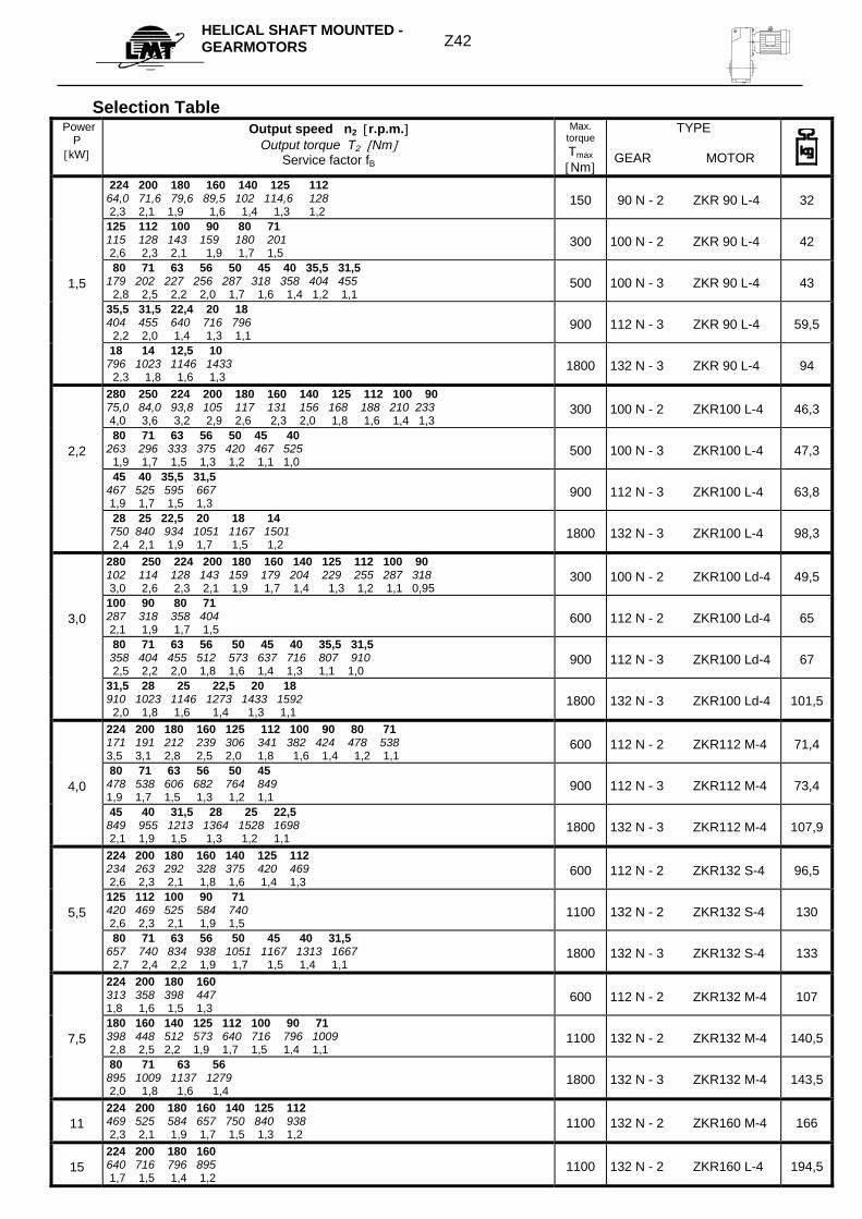
Z42 HELICAL SHAFT MOUNTED - GEARMOTORS
Selection Table
Power P
[kW]
Output speed n2 [r.p.m.] Output torque T2 [Nm]
Service factor fB
Max. torque Tmax [Nm]
TYPE
GEAR MOTOR
224 200 180 160 140 125 112 64,0 71,6 79,6 89,5 102 114,6 128 2,3 2,1 1,9 1,6 1,4 1,3 1,2
150 90 N - 2 ZKR 90 L-4 32
125 112 100 90 80 71 115 128 143 159 180 201 2,6 2,3 2,1 1,9 1,7 1,5
300 100 N - 2 ZKR 90 L-4 42
1,5
80 71 63 56 50 45 40 35,5 31,5 179 202 227 256 287 318 358 404 455 2,8 2,5 2,2 2,0 1,7 1,6 1,4 1,2 1,1
500 100 N - 3 ZKR 90 L-4 43
35,5 31,5 22,4 20 18 404 455 640 716 796 2,2 2,0 1,4 1,3 1,1
900 112 N - 3 ZKR 90 L-4 59,5
18 14 12,5 10 796 1023 1146 1433 2,3 1,8 1,6 1,3
1800 132 N - 3 ZKR 90 L-4 94
280 250 224 200 180 160 140 125 112 100 90 75,0 84,0 93,8 105 117 131 156 168 188 210 233 4,0 3,6 3,2 2,9 2,6 2,3 2,0 1,8 1,6 1,4 1,3
300 100 N - 2 ZKR100 L-4 46,3
2,2
80 71 63 56 50 45 40 263 296 333 375 420 467 525 1,9 1,7 1,5 1,3 1,2 1,1 1,0
500 100 N - 3 ZKR100 L-4 47,3
45 40 35,5 31,5 467 525 595 667 1,9 1,7 1,5 1,3
900 112 N - 3 ZKR100 L-4 63,8
28 25 22,5 20 18 14 750 840 934 1051 1167 1501 2,4 2,1 1,9 1,7 1,5 1,2
1800 132 N - 3 ZKR100 L-4 98,3
280 250 224 200 180 160 140 125 112 100 90 102 114 128 143 159 179 204 229 255 287 318 3,0 2,6 2,3 2,1 1,9 1,7 1,4 1,3 1,2 1,1 0,95
300 100 N - 2 ZKR100 Ld-4 49,5
3,0
100 90 80 71 287 318 358 404 2,1 1,9 1,7 1,5
600 112 N - 2 ZKR100 Ld-4 65
80 71 63 56 50 45 40 35,5 31,5 358 404 455 512 573 637 716 807 910 2,5 2,2 2,0 1,8 1,6 1,4 1,3 1,1 1,0
900 112 N - 3 ZKR100 Ld-4 67
31,5 28 25 22,5 20 18 910 1023 1146 1273 1433 1592 2,0 1,8 1,6 1,4 1,3 1,1
1800 132 N - 3 ZKR100 Ld-4 101,5
224 200 180 160 125 112 100 90 80 71 171 191 212 239 306 341 382 424 478 538 3,5 3,1 2,8 2,5 2,0 1,8 1,6 1,4 1,2 1,1
600 112 N - 2 ZKR112 M-4 71,4
4,0
80 71 63 56 50 45 478 538 606 682 764 849 1,9 1,7 1,5 1,3 1,2 1,1
900 112 N - 3 ZKR112 M-4 73,4
45 40 31,5 28 25 22,5 849 955 1213 1364 1528 1698 2,1 1,9 1,5 1,3 1,2 1,1
1800 132 N - 3 ZKR112 M-4 107,9
224 200 180 160 140 125 112 234 263 292 328 375 420 469 2,6 2,3 2,1 1,8 1,6 1,4 1,3
600 112 N - 2 ZKR132 S-4 96,5
5,5
125 112 100 90 71 420 469 525 584 740 2,6 2,3 2,1 1,9 1,5
1100 132 N - 2 ZKR132 S-4 130
80 71 63 56 50 45 40 31,5 657 740 834 938 1051 1167 1313 1667 2,7 2,4 2,2 1,9 1,7 1,5 1,4 1,1
1800 132 N - 3 ZKR132 S-4 133
224 200 180 160 313 358 398 447 1,8 1,6 1,5 1,3
600 112 N - 2 ZKR132 M-4 107
7,5
180 160 140 125 112 100 90 71 398 448 512 573 640 716 796 1009 2,8 2,5 2,2 1,9 1,7 1,5 1,4 1,1
1100 132 N - 2 ZKR132 M-4 140,5
80 71 63 56 895 1009 1137 1279 2,0 1,8 1,6 1,4
1800 132 N - 3 ZKR132 M-4 143,5
11
224 200 180 160 140 125 112 469 525 584 657 750 840 938 2,3 2,1 1,9 1,7 1,5 1,3 1,2
1100 132 N - 2 ZKR160 M-4 166
15
224 200 180 160 640 716 796 895 1,7 1,5 1,4 1,2
1100 132 N - 2 ZKR160 L-4 194,5
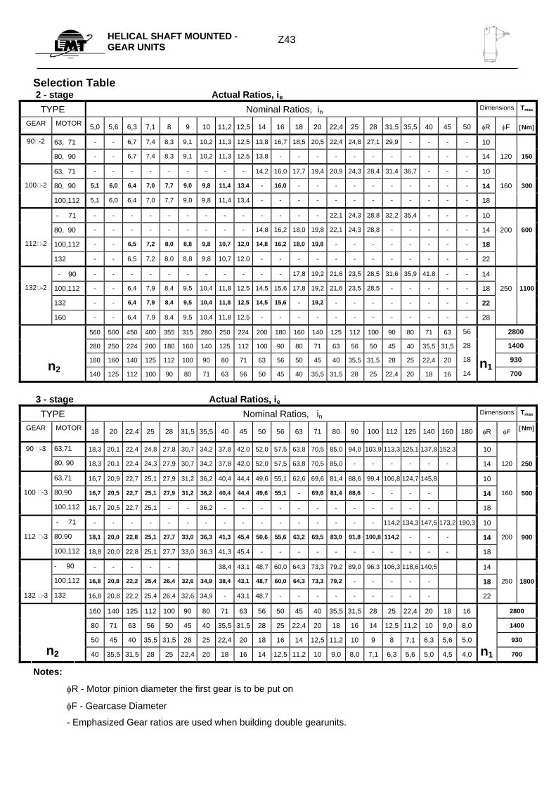
Z43HELICAL SHAFT MOUNTED -
GEAR UNITS
n1n2
n1
Selection Table 2 - stage Actual Ratios, ie
TYPE Nominal Ratios, in Dimensions Tmax
GEAR MOTOR 5,0 5,6 6,3 7,1 8 9 10 11,2 12,5 14 16 18 20 22,4 25 28 31,5 35,5 40 45 50 φR φF [Nm]
90-2 63, 71 - - 6,7 7,4 8,3 9,1 10,2 11,3 12,5 13,8 16,7 18,5 20,5 22,4 24,8 27,1 29,9 - - - - 10
80, 90 - - 6,7 7,4 8,3 9,1 10,2 11,3 12,5 13,8 - - - - - - - - - - - 14 120 150
63, 71 - - - - - - - - - 14,2 16,0 17,7 19,4 20,9 24,3 28,4 31,4 36,7 - - - 10
100-2 80, 90 5,1 6,0 6,4 7,0 7,7 9,0 9,8 11,4 13,4 - 16,0 - - - - - - - - - - 14 160 300
100,112 5,1 6,0 6,4 7,0 7,7 9,0 9,8 11,4 13,4 - - - - - - - - - - - - 18
- 71 - - - - - - - - - - - - - 22,1 24,3 28,8 32,2 35,4 - - - 10
80, 90 - - - - - - - - - 14,8 16,2 18,0 19,8 22,1 24,3 28,8 - - - - - 14 200 600
112-2 100,112 - - 6,5 7,2 8,0 8,8 9,8 10,7 12,0 14,8 16,2 18,0 19,8 - - - - - - - - 18
132 - - 6,5 7,2 8,0 8,8 9,8 10,7 12,0 - - - - - - - - - - - - 22
- 90 - - - - - - - - - - - 17,8 19,2 21,6 23,5 28,5 31,6 35,9 41.8 - - 14
132-2 100,112 - - 6,4 7,9 8,4 9,5 10,4 11,8 12,5 14,5 15,6 17,8 19,2 21,6 23,5 28,5 - - - - - 18 250 1100
132 - - 6,4 7,9 8,4 9,5 10,4 11,8 12,5 14,5 15,6 - 19,2 - - - - - - - - 22
160 - - 6,4 7,9 8,4 9,5 10,4 11,8 12,5 - - - - - - - - - - - - 28
560 500 450 400 355 315 280 250 224 200 180 160 140 125 112 100 90 80 71 63 56 2800
280 250 224 200 180 160 140 125 112 100 90 80 71 63 56 50 45 40 35,5 31,5 28 1400
180 160 140 125 112 100 90 80 71 63 56 50 45 40 35,5 31,5 28 25 22,4 20 18 930
140 125 112 100 90 80 71 63 56 50 45 40 35,5 31,5 28 25 22,4 20 18 16 14 700
3 - stage Actual Ratios, ie
TYPE Nominal Ratios, in Dimensions Tmax
GEAR MOTOR 18 20 22,4 25 28 31,5 35,5 40 45 50 56 63 71 80 90 100 112 125 140 160 180 φR φF [Nm]
90 -3 63,71 18,3 20,1 22,4 24,8 27,8 30,7 34,2 37,8 42,0 52,0 57,5 63,8 70,5 85,0 94,0 103,9 113,3 125,1 137,8 152,3 10
80, 90 18,3 20,1 22,4 24,3 27,9 30,7 34,2 37,8 42,0 52,0 57,5 63,8 70,5 85,0 - - - - - - 14 120 250
63,71 16,7 20,9 22,7 25,1 27,9 31,2 36,2 40,4 44,4 49,6 55,1 62,6 69,6 81,4 88,6 99,4 106,8 124,7 145,8 10
100 -3 80,90 16,7 20,5 22,7 25,1 27,9 31,2 36,2 40,4 44,4 49,6 55,1 - 69,6 81,4 88,6 - - - - 14 160 500
100,112 16,7 20,5 22,7 25,1 - - 36,2 - - - - - - - - - - - - 18
- 71 - - - - - - - - - - - - - - - - 114,2 134,3 147,5 173,2 190,3 10
112 -3 80,90 18,1 20,0 22,8 25,1 27,7 33,0 36,3 41,3 45,4 50,6 55,6 63,2 69,5 83,0 91,8 100,8 114,2 - - - 14 200 900
100,112 18,8 20,0 22,8 25,1 27,7 33,0 36,3 41,3 45,4 - - - - - - - - - - - 18
- 90 - - - - - 38,4 43,1 48,7 60,0 64,3 73,3 79,2 89,0 96,3 106,3 118,6 140,5 14
100,112 16,8 20,8 22,2 25,4 26,4 32,6 34,9 38,4 43,1 48,7 60,0 64,3 73,3 79,2 - - - - - 18 250 1800
132 -3 132 16,8 20,8 22,2 25,4 26,4 32,6 34,9 - 43,1 48,7 - - - - - - - - - 22
160 140 125 112 100 90 80 71 63 56 50 45 40 35,5 31,5 28 25 22,4 20 18 16 2800
80 71 63 56 50 45 40 35,5 31,5 28 25 22,4 20 18 16 14 12,5 11,2 10 9,0 8,0 1400
50 45 40 35,5 31,5 28 25 22,4 20 18 16 14 12,5 11,2 10 9 8 7,1 6,3 5,6 5,0 930
40 35,5 31,5 28 25 22,4 20 18 16 14 12,5 11,2 10 9.0 8.0 7,1 6,3 5,6 5,0 4,5 4,0 700
Notes:
φR - Motor pinion diameter the first gear is to be put on
φF - Gearcase Diameter
- Emphasized Gear ratios are used when building double gearunits.
n2
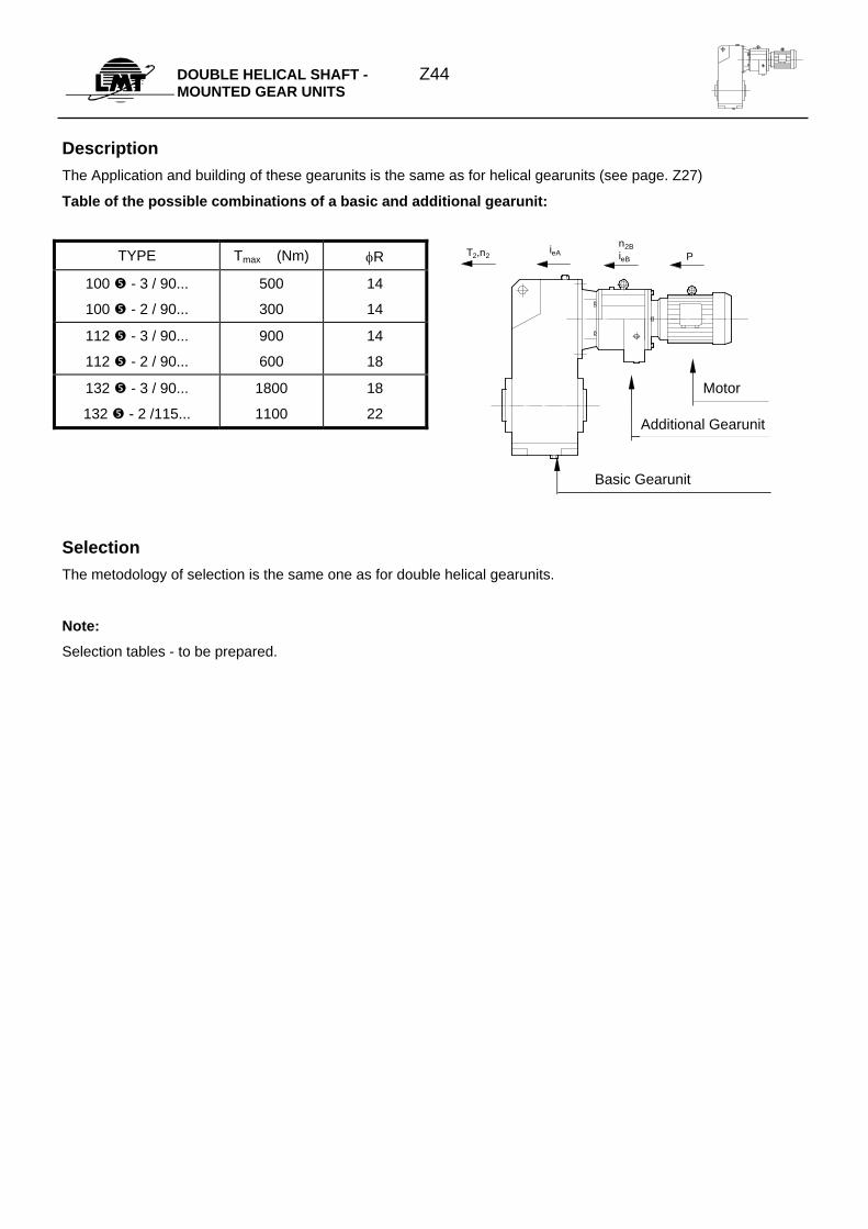
DOUBLE HELICAL SHAFT - MOUNTED GEAR UNITS
Z44
Description The Application and building of these gearunits is the same as for helical gearunits (see page. Z27)
Table of the possible combinations of a basic and additional gearunit:
TYPE Tmax (Nm) φR
100 - 3 / 90...
100 - 2 / 90...
500
300
14
14
112 - 3 / 90...
112 - 2 / 90...
900
600
14
18
132 - 3 / 90...
132 - 2 /115...
1800
1100
18
22
Selection The metodology of selection is the same one as for double helical gearunits.
Note:
Selection tables - to be prepared.
PieAT2,n2n2BieB
Motor
Additional Gearunit
Basic Gearunit
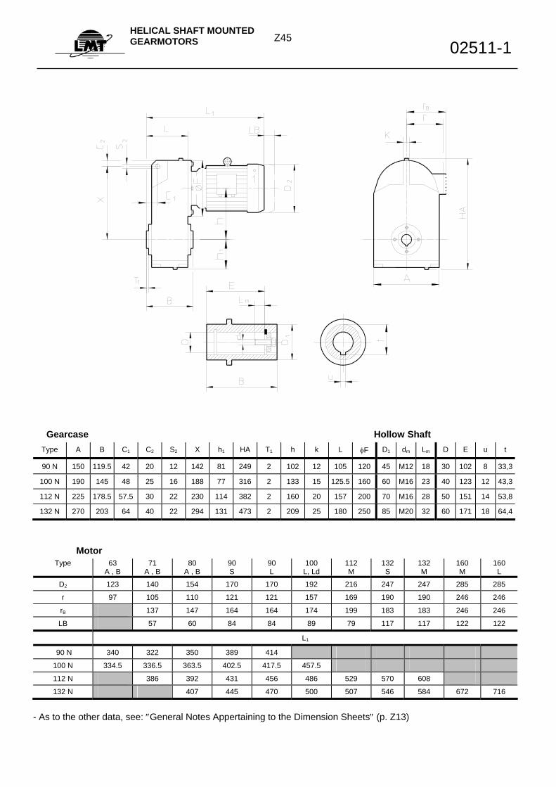
Z45 HELICAL SHAFT MOUNTED GEARMOTORS 02511-1
Gearcase Hollow Shaft
Type A B C1 C2 S2 X h1 HA T1 h k L φF D1 dm Lm D E u t
90 N 150 119.5 42 20 12 142 81 249 2 102 12 105 120 45 M12 18 30 102 8 33,3
100 N 190 145 48 25 16 188 77 316 2 133 15 125.5 160 60 M16 23 40 123 12 43,3
112 N 225 178.5 57.5 30 22 230 114 382 2 160 20 157 200 70 M16 28 50 151 14 53,8
132 N 270 203 64 40 22 294 131 473 2 209 25 180 250 85 M20 32 60 171 18 64,4
Motor Type 63
A , B 71
A , B 80
A , B 90 S
90 L
100 L, Ld
112 M
132 S
132 M
160 M
160 L
D2 123 140 154 170 170 192 216 247 247 285 285
r 97 105 110 121 121 157 169 190 190 246 246
rB 137 147 164 164 174 199 183 183 246 246
LB 57 60 84 84 89 79 117 117 122 122
L1
90 N 340 322 350 389 414
100 N 334.5 336.5 363.5 402.5 417.5 457.5
112 N 386 392 431 456 486 529 570 608
132 N 407 445 470 500 507 546 584 672 716
- As to the other data, see: ″General Notes Appertaining to the Dimension Sheets″ (p. Z13)
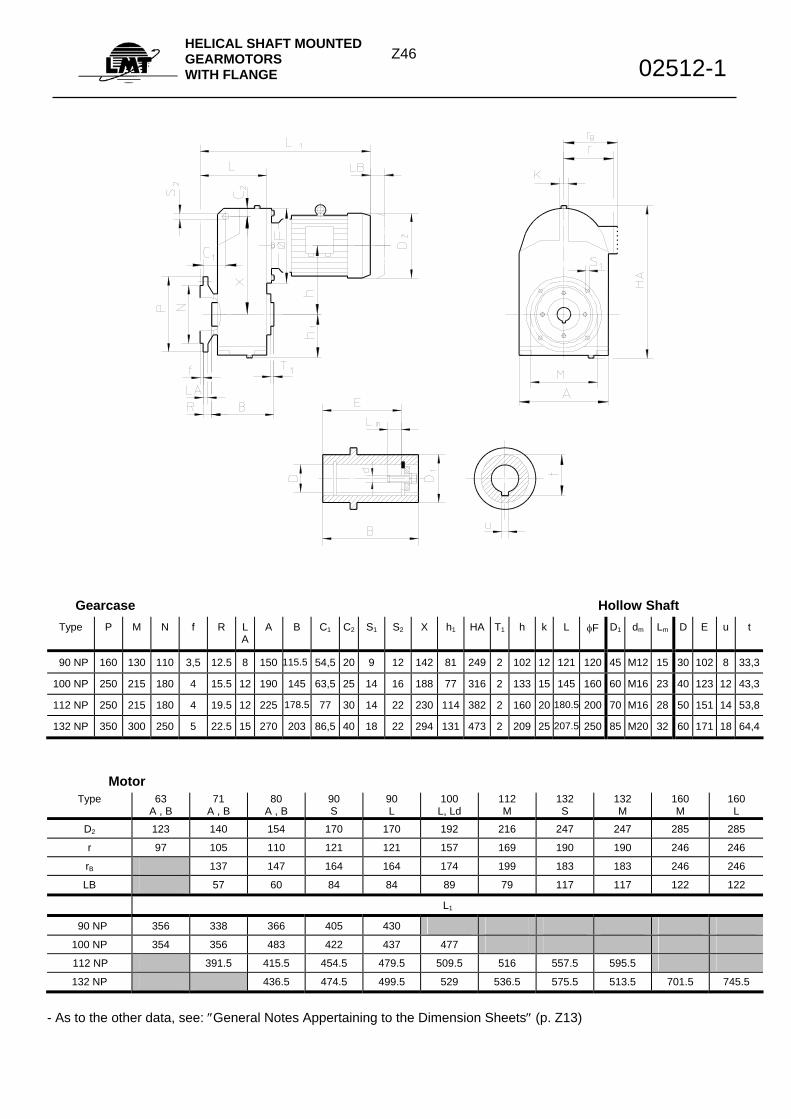
Z46HELICAL SHAFT MOUNTED GEARMOTORS WITH FLANGE 02512-1
Gearcase Hollow Shaft
Type P M N f R LA
A B C1 C2 S1 S2 X h1 HA T1 h k L φF D1 dm Lm D E u t
90 NP 160 130 110 3,5 12.5 8 150 115.5 54,5 20 9 12 142 81 249 2 102 12 121 120 45 M12 15 30 102 8 33,3
100 NP 250 215 180 4 15.5 12 190 145 63,5 25 14 16 188 77 316 2 133 15 145 160 60 M16 23 40 123 12 43,3
112 NP 250 215 180 4 19.5 12 225 178.5 77 30 14 22 230 114 382 2 160 20 180.5 200 70 M16 28 50 151 14 53,8
132 NP 350 300 250 5 22.5 15 270 203 86,5 40 18 22 294 131 473 2 209 25 207.5 250 85 M20 32 60 171 18 64,4
Motor Type 63
A , B 71
A , B 80
A , B 90 S
90 L
100 L, Ld
112 M
132 S
132 M
160 M
160 L
D2 123 140 154 170 170 192 216 247 247 285 285
r 97 105 110 121 121 157 169 190 190 246 246
rB 137 147 164 164 174 199 183 183 246 246
LB 57 60 84 84 89 79 117 117 122 122
L1
90 NP 356 338 366 405 430
100 NP 354 356 483 422 437 477
112 NP 391.5 415.5 454.5 479.5 509.5 516 557.5 595.5
132 NP 436.5 474.5 499.5 529 536.5 575.5 513.5 701.5 745.5
- As to the other data, see: ″General Notes Appertaining to the Dimension Sheets″ (p. Z13)
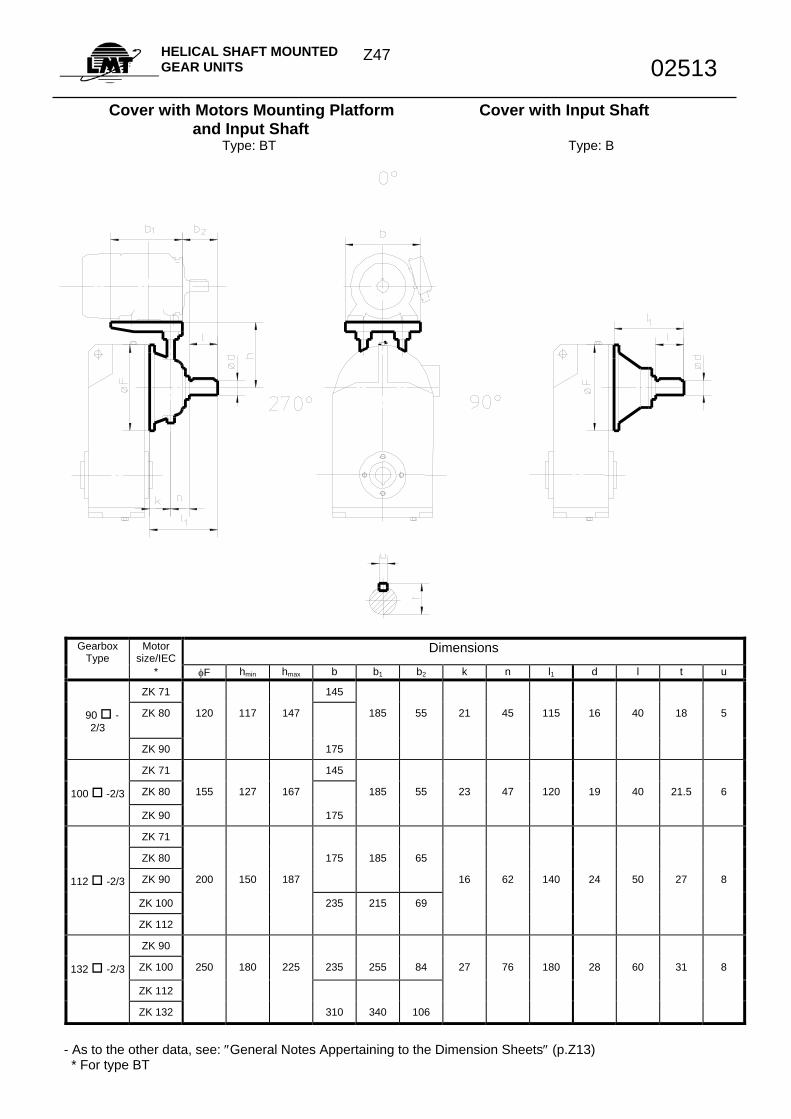
Z47 HELICAL SHAFT MOUNTED GEAR UNITS 02513
Cover with Motors Mounting Platform Cover with Input Shaft and Input Shaft Type: BT Type: B
Gearbox Type
Motor size/IEC
Dimensions
* φF hmin hmax b b1 b2 k n l1 d l t u
ZK 71 145
90 -2/3
ZK 80 120 117 147 185 55 21 45 115 16 40 18 5
ZK 90 175
ZK 71 145
100 -2/3 ZK 80 155 127 167 185 55 23 47 120 19 40 21.5 6
ZK 90 175
ZK 71
ZK 80 175 185 65
112 -2/3 ZK 90 200 150 187 16 62 140 24 50 27 8
ZK 100 235 215 69
ZK 112
ZK 90
132 -2/3 ZK 100 250 180 225 235 255 84 27 76 180 28 60 31 8
ZK 112
ZK 132 310 340 106
- As to the other data, see: ″General Notes Appertaining to the Dimension Sheets″ (p.Z13) * For type BT
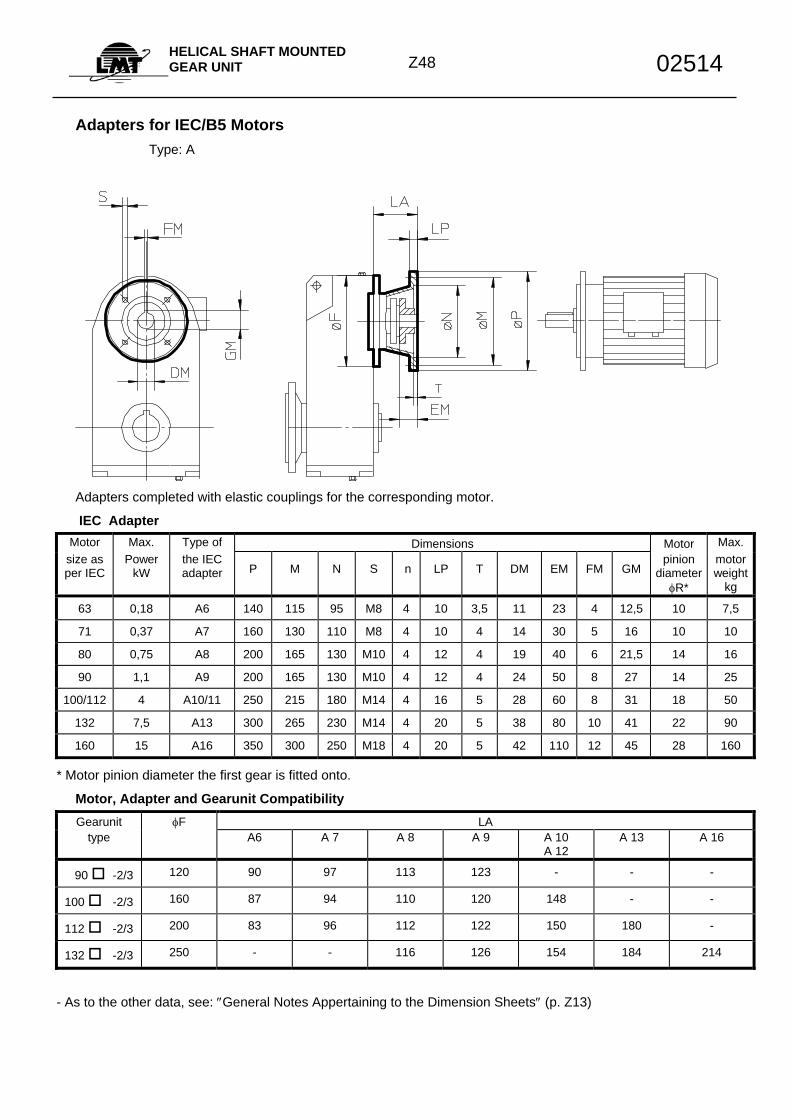
Z48
HELICAL SHAFT MOUNTED GEAR UNIT 02514
Adapters for IEC/B5 Motors
Type: A
Adapters completed with elastic couplings for the corresponding motor.
IEC Adapter Motor Max. Type of Dimensions Motor Max.
size as per IEC
Power kW
the IEC adapter P M N S n LP T DM EM FM GM
pinion diameter
φR*
motor weight
kg
63 0,18 A6 140 115 95 M8 4 10 3,5 11 23 4 12,5 10 7,5
71 0,37 A7 160 130 110 M8 4 10 4 14 30 5 16 10 10
80 0,75 A8 200 165 130 M10 4 12 4 19 40 6 21,5 14 16
90 1,1 A9 200 165 130 M10 4 12 4 24 50 8 27 14 25
100/112 4 A10/11 250 215 180 M14 4 16 5 28 60 8 31 18 50
132 7,5 A13 300 265 230 M14 4 20 5 38 80 10 41 22 90
160 15 A16 350 300 250 M18 4 20 5 42 110 12 45 28 160
* Motor pinion diameter the first gear is fitted onto.
Motor, Adapter and Gearunit Compatibility Gearunit φF LA
type A6 A 7 A 8 A 9 A 10 A 12
A 13 A 16
90 -2/3 120 90 97 113 123 - - -
100 -2/3 160 87 94 110 120 148 - -
112 -2/3 200 83 96 112 122 150 180 -
132 -2/3 250 - - 116 126 154 184 214
- As to the other data, see: ″General Notes Appertaining to the Dimension Sheets″ (p. Z13)
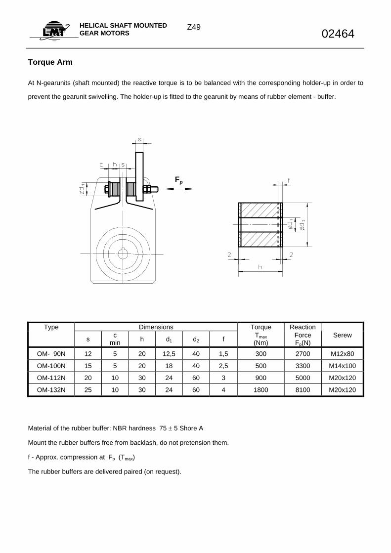
Z49HELICAL SHAFT MOUNTED GEAR MOTORS 02464
Torque Arm
At N-gearunits (shaft mounted) the reactive torque is to be balanced with the corresponding holder-up in order to
prevent the gearunit swivelling. The holder-up is fitted to the gearunit by means of rubber element - buffer.
Fp
Type Dimensions Torque Reaction s c
min h d1 d2 f Tmax (Nm)
Force Fp(N)
Serew
OM- 90N 12 5 20 12,5 40 1,5 300 2700 M12x80
OM-100N 15 5 20 18 40 2,5 500 3300 M14x100
OM-112N 20 10 30 24 60 3 900 5000 M20x120
OM-132N 25 10 30 24 60 4 1800 8100 M20x120
Material of the rubber buffer: NBR hardness 75 ± 5 Shore A
Mount the rubber buffers free from backlash, do not pretension them.
f - Approx. compression at Fp (Tmax)
The rubber buffers are delivered paired (on request).
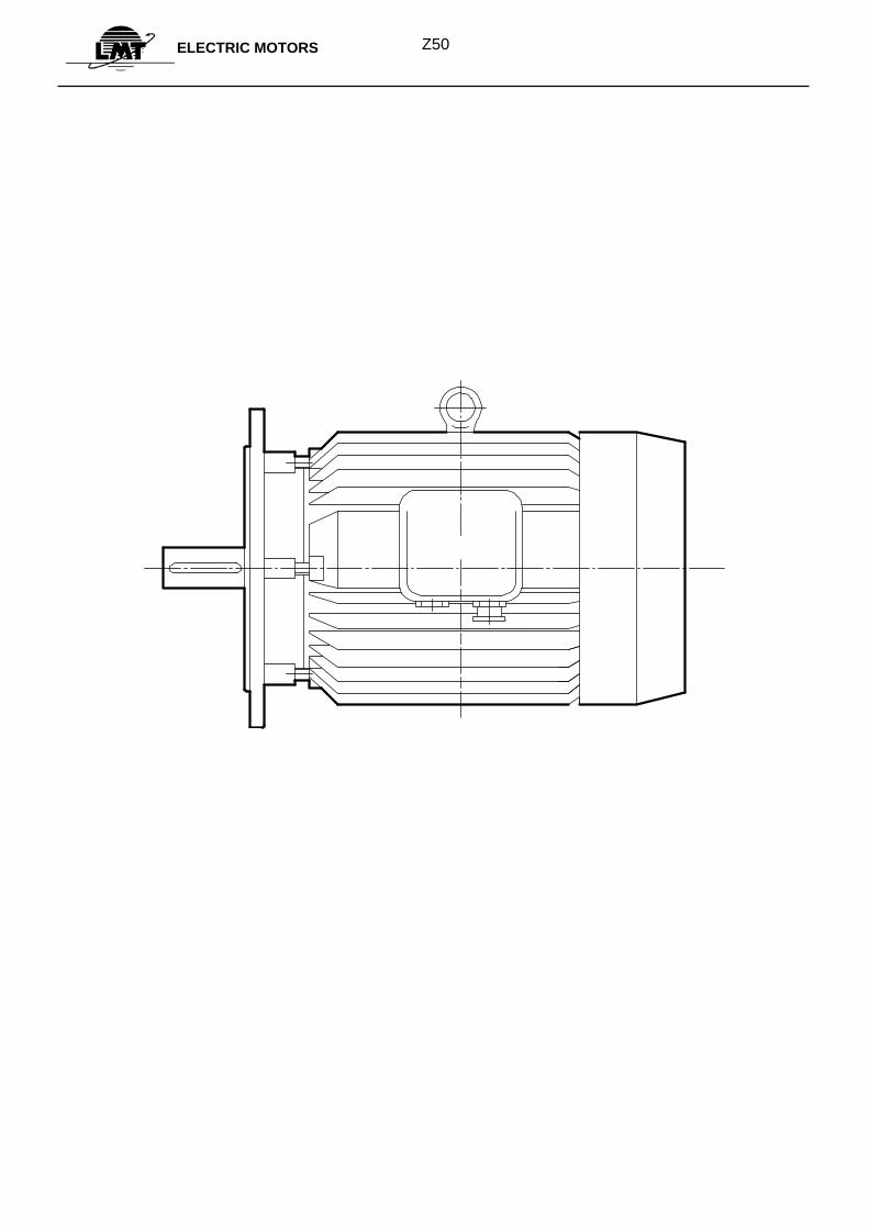
Z50 ELECTRIC MOTORS
Z51ELECTRIC MOTORS
Introduction The basic execution of gearmotors the ZKR type of reducer threephase asynchronous motors with cage rotor are mostly used. Compared to ZK type of standard IEC motors their mechanical characteristics slightly differ while their electric characteristics are identical. The electric motors type ZK with mounting positions B5 and B3 could be coupled with gearunits by means of input assemblies, if requested so. Technical Description
Basic execution: type ZKR, 4-poles
- Enclosure: IP54/IP55 standard, other enclosures on request
- Mounting position: B5 flanges as per DIN 42948
- Specific features of the mech.exe.: Reinforced bearing bedings and the shaft; flange and shaft coupling dimensions particularly adjusted to gearunits
- Motor ribbed housing:
* up to size 112: high quality Al alloy
* over size 112: grey iron
- Flanges for all sizes of motors: grey iron
- Cooling: external as per IEC 34-6, IC 01 41,the external cooling fan is under a
special cover and is made of:
* up to size 180: polypropylene
* over size 180: Al alloys
- Bearings: roller, bearings, beyond size 200 a connection for an external grease
nipple is fitted.
- Terminal Box: on the right, shaft pinion head viewed 4x90o revolving cable inlet,
beginning with size 160.
- Winding Insulation: ″F″ class, enabling a temperature rise up to 105oC over ambiental
temperature of 40°C; ″H″ class is also possible (140oC over 40oC)
- Voltage and Frequency: 3 x 380V, 50Hz, voltages up to 690 V and frequencies from
42 to 60 Hz - on request
- Winding Connection:
* up to 1,5 kW:
* over 1,5 kW:
- Power: Powers given in selection tables: for continuous duty S1, connected to
the network with nominal voltage, nominal frequency, ambiental
temperature up to 40oC and operation in the altitude up to 1000 m above
sea level.
- Speed: (rpm) Gearunits standardly use 4-poles electric motors
(asynchronous, rpm: 1400 min-1)
- Vibrations: The motors have full key dinamically balanced rotors and do comply the
vibraton level N as per DIN ISO 2373 and noise level as per IEC 34-9.
Brake Motors
star ( Υ ) 220 V ∆ / 380 VΥ 220 V ∆ / 400 VΥ delta ( ∆ ) 380 V∆ / 660 VΥ 400 V∆ / 690 VΥ
Z52ELECTRIC MOTORS
The brake motors are built out of a basic type of gear motors, ZKR.Their length is different because of the space meant for the brake.The brake gets fed by the inverter built-in into the terminal box. The inverter′s standard voltage is of 230 or 400 V. The braking torques are adjusted to their max. values, they can be reduced to 75 or 50% of their max. value taking off 2 or 4 springs from the brake. - Hard fan: For the brake motors the, so called, grey iron hard fans are delivered, on request. They find their
application at drives which require both soft starting and soft braking (driving, lifting, etc.) Other Motors All the other electric motors such as: - 2,6 and 8 - poles motors - Two (and multiple speed) motors with 1 winding, 4/2, 8/4, 6/4, 8/6, 8/2, 12/2 could be coupled with gearunits. - Single phase motors - Other motors, such as: motors with Eex enclosure, DC electric motors, etc. Other Special Features: Duty tupes: If S2 (duty with limited duration) and S3 (intermittent duty) working regimes are requested the motors can be loaded
with power bigger than the rated one. As to these and the other types od working regimes the choice of the
adequate type and size of the motor is to be done on a basis of the complete working conditions. All of the above
mentioned refers also to the motors running in a non-standard ambients. In those cases it is recommendable to
contact our Technical Advice Service. Motor protection:
All the electric motors can be fitted with PTC thermal detectors built-in into the windings in order to realize the
complete thermal protection of the motor. A motor protective assembly is used as a protection from overloading
and two phase motor duty. Tolerances: As far as the technical data of threephase asynchronous cage motors are concerned these are the permissible aberrations according to EN 60034/IEC 34-1:
Power factor cos′ϕ: −−1
6cosϕ
Voltage and frequency: at rated power and rated frequency fn the permissible deviation of rated voltage is “5%.
Slippage: “ 20% at Pn ≥ 1 kW
“ 30% at Pn <1 kW
(in hot state and at nominal loading)
Starting torque: -15% up to +25%
Break-away torque: -10%, not less than 1,6 Tn
Inertia moment: “10%
Efficiency: * for Pn ≤ 50 kW: - 0,15 ( 1-η )
* for Pn > 50 kW: - 0,1 ( 1-η )
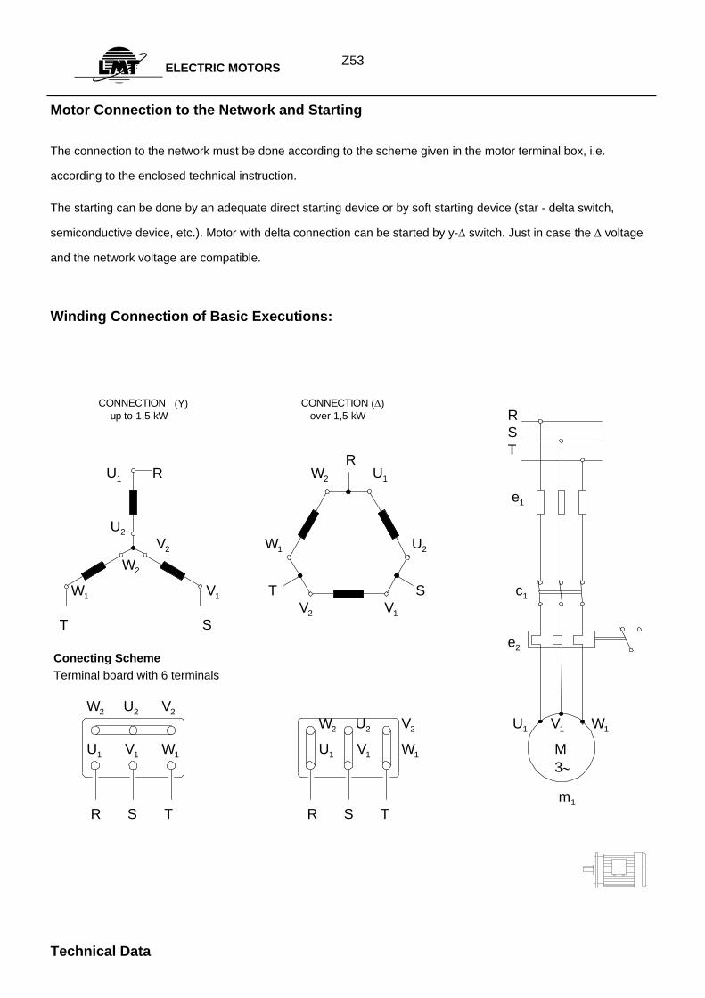
Z53ELECTRIC MOTORS
Motor Connection to the Network and Starting
The connection to the network must be done according to the scheme given in the motor terminal box, i.e.
according to the enclosed technical instruction.
The starting can be done by an adequate direct starting device or by soft starting device (star - delta switch,
semiconductive device, etc.). Motor with delta connection can be started by y-∆ switch. Just in case the ∆ voltage
and the network voltage are compatible.
Winding Connection of Basic Executions:
R S T
U1 R W2 U1
e1
U2 V2 W1 U2
W2
W1 V1 T S c1 V2 V1
T S e2
W2 U2 V2 W2 U2 V2 U1 V1 W1
U1 V1 W1 U1 V1 W1 M 3∼
m1 R S T R S T
R
CONNECTION (Y) CONNECTION (∆) up to 1,5 kW over 1,5 kW
Technical Data
Conecting Scheme Terminal board with 6 terminals
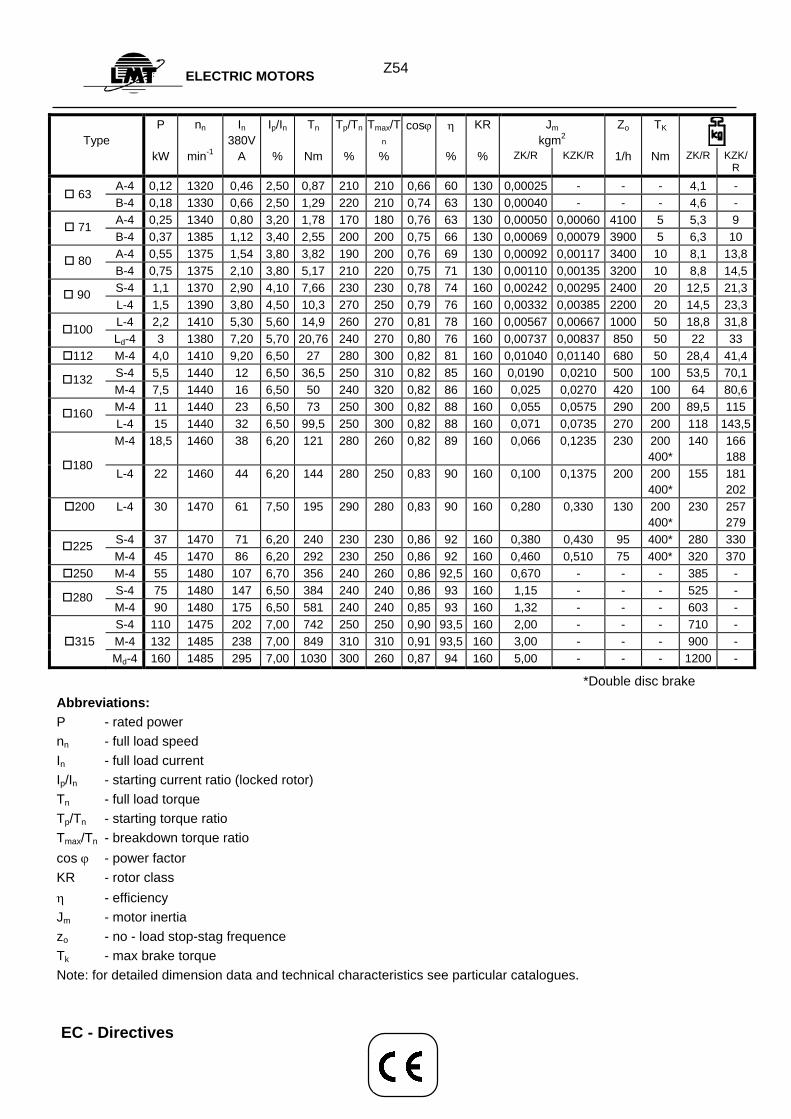
Z54ELECTRIC MOTORS
Type
P nn In 380V
Ip/In Tn Tp/Tn Tmax/Tn
cosϕ η KR Jm kgm2
Zo
TK
kW min-1 A % Nm % % % % ZK/R KZK/R 1/h Nm ZK/R KZK/R
A-4 0,12 1320 0,46 2,50 0,87 210 210 0,66 60 130 0,00025 - - - 4,1 - B-4 0,18 1330 0,66 2,50 1,29 220 210 0,74 63 130 0,00040 - - - 4,6 - A-4 0,25 1340 0,80 3,20 1,78 170 180 0,76 63 130 0,00050 0,00060 4100 5 5,3 9 B-4 0,37 1385 1,12 3,40 2,55 200 200 0,75 66 130 0,00069 0,00079 3900 5 6,3 10 A-4 0,55 1375 1,54 3,80 3,82 190 200 0,76 69 130 0,00092 0,00117 3400 10 8,1 13,8 B-4 0,75 1375 2,10 3,80 5,17 210 220 0,75 71 130 0,00110 0,00135 3200 10 8,8 14,5 S-4 1,1 1370 2,90 4,10 7,66 230 230 0,78 74 160 0,00242 0,00295 2400 20 12,5 21,3 L-4 1,5 1390 3,80 4,50 10,3 270 250 0,79 76 160 0,00332 0,00385 2200 20 14,5 23,3 L-4 2,2 1410 5,30 5,60 14,9 260 270 0,81 78 160 0,00567 0,00667 1000 50 18,8 31,8 Ld-4 3 1380 7,20 5,70 20,76 240 270 0,80 76 160 0,00737 0,00837 850 50 22 33
112 M-4 4,0 1410 9,20 6,50 27 280 300 0,82 81 160 0,01040 0,01140 680 50 28,4 41,4 S-4 5,5 1440 12 6,50 36,5 250 310 0,82 85 160 0,0190 0,0210 500 100 53,5 70,1 M-4 7,5 1440 16 6,50 50 240 320 0,82 86 160 0,025 0,0270 420 100 64 80,6 M-4 11 1440 23 6,50 73 250 300 0,82 88 160 0,055 0,0575 290 200 89,5 115 L-4 15 1440 32 6,50 99,5 250 300 0,82 88 160 0,071 0,0735 270 200 118 143,5 M-4 18,5 1460 38 6,20 121 280 260 0,82 89 160 0,066 0,1235 230 200
400*140 166
188 L-4 22 1460 44 6,20 144 280 250 0,83 90 160 0,100 0,1375 200 200
400*155 181
202 200 L-4 30 1470 61 7,50 195 290 280 0,83 90 160 0,280 0,330 130 200
400*230 257
279 S-4 37 1470 71 6,20 240 230 230 0,86 92 160 0,380 0,430 95 400* 280 330 M-4 45 1470 86 6,20 292 230 250 0,86 92 160 0,460 0,510 75 400* 320 370
250 M-4 55 1480 107 6,70 356 240 260 0,86 92,5 160 0,670 - - - 385 - S-4 75 1480 147 6,50 384 240 240 0,86 93 160 1,15 - - - 525 - M-4 90 1480 175 6,50 581 240 240 0,85 93 160 1,32 - - - 603 - S-4 110 1475 202 7,00 742 250 250 0,90 93,5 160 2,00 - - - 710 -
315 M-4 132 1485 238 7,00 849 310 310 0,91 93,5 160 3,00 - - - 900 - Md-4 160 1485 295 7,00 1030 300 260 0,87 94 160 5,00 - - - 1200 -
*Double disc brake Abbreviations: P - rated power nn - full load speed In - full load current Ip/In - starting current ratio (locked rotor) Tn - full load torque Tp/Tn - starting torque ratio Tmax/Tn - breakdown torque ratio cos ϕ - power factor KR - rotor class η - efficiency Jm - motor inertia zo - no - load stop-stag frequence Tk - max brake torque Note: for detailed dimension data and technical characteristics see particular catalogues. EC - Directives
63
71
80
90
100
132
160
180
225
280
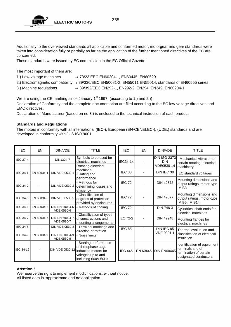
Z55ELECTRIC MOTORS
Additionally to the overviewed standards all applicable and conformed motor, motorgear and gear standards were taken into consideration fully or partially as far as the application of the further mentioned directives of the EC are concerned. These standards were issued by EC commission in the EC Official Gazette. The most important of them are: 1.) Low-voltage machines → 73/23 EEC EN60204-1, EN60445, EN60529 2.) Electromagnetic compatibility → 89/336/EEC EN50081-2, EN55011 EN55014, standards of EN60555 series 3.) Machine regulations → 89/392/EEC EN292-1, EN292-2, EN294, EN349, EN60204-1 We are using the CE marking since January 1st 1997. (according to 1.) and 2.)) Declaration of Conformity and the complete documentation are filed according to the EC low-voltage directives and EMC directives. Declaration of Manufacturer (based on no.3.) is enclosed to the technical instruction of each product. Standards and Regulations The motors in conformity with all international (IEC-), European (EN-CENELEC-), (UDE,) standards and are developed in conformity with JUS ISO 9001.
IEC EN DIN/VDE TITLE
IEC 27-4 - DIN1304-7 Symbols to be used for electrical machines
IEC 34-1
EN 60034-1
DIN VDE 0530-1
Rotating electrical machines: - Rating and performance
IEC 34-2
-
DIN VDE 0530-2
- Methods for determining losses and efficiency
IEC 34-5
EN 60034-5
DIN VDE 0530-5
- Classification of degrees of protection provided by enclosures
IEC 34-6 EN 60034-6
DIN EN 60034-6 VDE 0530-6
- Methods of cooling
IEC 34-7
EN 60034-7
DIN EN 60034-7
VDE 0530-7
- Classification of types of constructions and mounting arrangements
IEC 34-8 - DIN VDE 0530-8 - Terminal markings and direction of rotation
IEC 34-9 EN 60034-9 DIN EN 60034-9 VDE 0530-9
- Noise limits
IEC 34-12
-
DIN VDE 0530-12
- Starting performance of threephase cage induction motors for voltages up to and including 660V,50Hz
IEC EN DIN/VDE TITLE
IEC34-14
-
DIN ISO 2373 DIN
VDE0530-14
- Mechanical vibration of certain rotating electrical machinery
IEC 38 - DIN IEC 38 IEC standard voltages
IEC 72 -
DIN 42673
Mounting dimensions and output ratings, motor-type IM B3
IEC 72
-
DIN 42677
Mounting dimensions and output ratings, motor-type IM B5, IM B14
IEC 72 - DIN 748-3 Cylindrical shaft ends for electrical machines
IEC 72-2 - DIN 42948 Mounting flanges for electrical machines
IEC 85 - DIN IEC 85 VDE 0301-1
Thermal evaluation and classification of electrical insulation
IEC 445
EN 60445
DIN EN60445
Identification of equipment terminals and of termination of certain designated conductors
Atention ! We reserve the right to implement modicifications, without notice. All listed data is approximate and no obbligation.
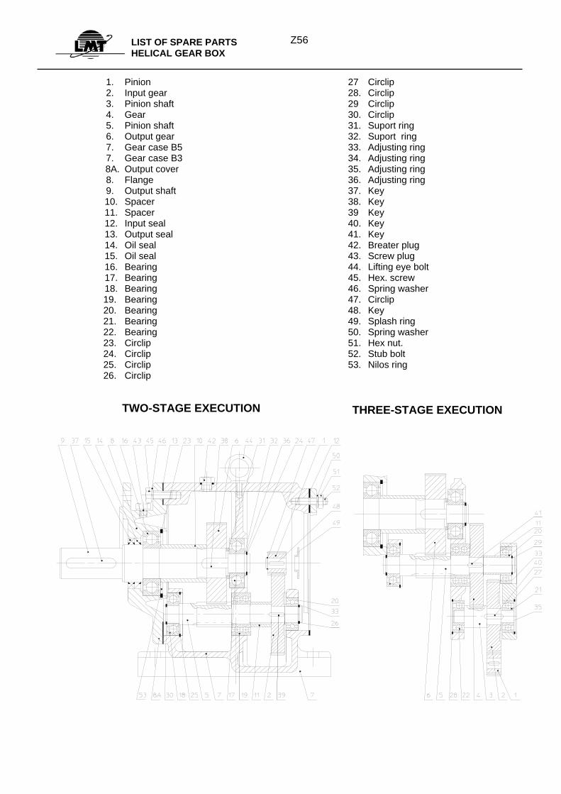
Z56LIST OF SPARE PARTS
HELICAL GEAR BOX
1. 2. 3. 4. 5. 6. 7. 7.
8A. 8. 9.
10. 11. 12. 13. 14. 15. 16. 17. 18. 19. 20. 21. 22. 23. 24. 25. 26.
Pinion Input gear Pinion shaft Gear Pinion shaft Output gear Gear case B5 Gear case B3 Output cover Flange Output shaft Spacer Spacer Input seal Output seal Oil seal Oil seal Bearing Bearing Bearing Bearing Bearing Bearing Bearing Circlip Circlip Circlip Circlip
27 28.29 30. 31. 32. 33. 34. 35. 36. 37. 38.39 40. 41. 42. 43. 44. 45. 46. 47. 48. 49. 50. 51. 52. 53.
Circlip Circlip Circlip Circlip Suport ring Suport ring Adjusting ring Adjusting ring Adjusting ring Adjusting ring Key Key Key Key Key Breater plug Screw plug Lifting eye bolt Hex. screw Spring washer Circlip Key Splash ring Spring washer Hex nut. Stub bolt Nilos ring
TWO-STAGE EXECUTION THREE-STAGE EXECUTION
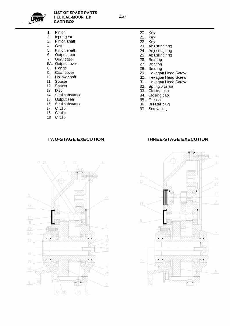
Z57
LIST OF SPARE PARTS HELICAL-MOUNTED GAER BOX
1. 2. 3. 4. 5. 6. 7.
8A. 8. 9.
10. 11. 12. 13. 14. 15. 16. 17. 18. 19
Pinion Input gear Pinion shaft Gear Pinion shaft Output gear Gear case Output cover Flange Gear cover Hollow shaft Spacer Spacer Disc Seal substance Output seal Seal substance Circlip Circlip Circlip
20. 21. 22. 23. 24. 25. 26. 27. 28. 29. 30. 31. 32. 33. 34. 35. 36. 37.
Key Key Key Adjusting ring Adjusting ring Adjusting ring Bearing Bearing Bearing Hexagon Head Screw Hexagon Head Screw Hexagon Head Screw Spring washer Closing cap Closing cap Oil seal Breater plug Screw plug
TWO-STAGE EXECUTION THREE-STAGE EXECUTION
Recommended