Lossless Image Compression and
Secure Storage of Medical Images
Vivekananda Panigrahy
Department of Computer Science and Engineering
National Institute of Technology Rourkela
Rourkela-769 008, Orissa, India
Lossless Image Compression and Secure Storage
of Medical Images
Thesis submitted on MAY 2012 in partial fulfilment
of the requirements for the degree of
Bachelor of Technology
in
Computer Science and Engineering
by
Vivekananda Panigrahy
(Roll: 108CS022)
under the guidance of
Prof. B. Majhi
NIT Rourkela
Department of Computer Science and Engineering
National Institute of Technology Rourkela
Rourkela-769 008, Orissa, India
Academic Year: 2011-12
Department of Computer Science
National Institute of Technology Rourkela
Rourkela-769 008, Orissa, India.
May 14, 2012
Certificate
This is to certify that the work in the thesis entitled Lossless Image Compression
and Secure Storage of Medical Images by Vivekananda Panigrahy is a
record of an original research work carried out under my supervision and guidance
in partial fulfillment of the requirements for the award of the degree of Bachelor of
Technology in Computer Science and Engineering. Neither this thesis nor any part
of it has been submitted for any degree or academic award elsewhere.
B. Majhi
Professor
CSE department of NIT Rourkela
Acknowledgement
I express my sincere gratitude to Prof. B. Majhi for his motivation during the course
of the project which served as a spur to keep the work on schedule.
I convey my regards to all the other faculty members of Department of Computer
Science and Engineering, NIT Rourkela for their valuable guidance and advices at
appropriate times. Finally, I would like to thank my friends for their help and assis-
tance all through this project.
Vivekananda Panigrahy
Abstract
This thesis presents a new methodology which performs both lossless compression and
secure storage of binary and gray scale images. The compression is based on SCAN
language and it is lossless in nature. The SCAN is a formal language-based two-
dimensional spatial-accessing methodology which can efficiently specify and generate
a wide range of scanning paths or space filling curves. Prior to the compression, a
framework is presented which ensures the secure storage of images on basis of division
of knowledge. Finally, QR code is used for efficient indexing of the secure images.
QR codes are 2-dimensional barcodes which can store huge amount of data as com-
pared to 1-dimensional barcodes. The results are analysed constrained to medical
images in the hope of getting better results than that of the generic domain. Thus,
this paper presents compression specific SCAN language, compression-decompression
algorithms, framework ensuring security and indexing, and test results of the method-
ology.
Keywords: Medical Images, Lossless Compression, SCAN Language, QR Code
Contents
Certificate iii
Acknowledgement iv
Abstract v
List of Figures viii
List of Tables ix
1 Introduction 1
1.1 Objective . . . . . . . . . . . . . . . . . . . . . . . . . . . . . . . . . 1
1.2 Image Compression . . . . . . . . . . . . . . . . . . . . . . . . . . . . 2
1.3 Image Security . . . . . . . . . . . . . . . . . . . . . . . . . . . . . . 3
1.4 Medical Imaging . . . . . . . . . . . . . . . . . . . . . . . . . . . . . 4
1.5 Quick Response Code . . . . . . . . . . . . . . . . . . . . . . . . . . . 4
1.6 Organization of the Thesis . . . . . . . . . . . . . . . . . . . . . . . . 6
2 SCAN based Language 7
2.1 Definition of Compression specific SCAN . . . . . . . . . . . . . . . . 8
2.2 Semantics of Compression specific SCAN . . . . . . . . . . . . . . . . 8
2.3 Encoding of Compressed Image . . . . . . . . . . . . . . . . . . . . . 10
2.4 Example of encoding of compressed image . . . . . . . . . . . . . . . 11
3 Compression and Decompression 13
3.1 Compression . . . . . . . . . . . . . . . . . . . . . . . . . . . . . . . . 13
3.2 Decompression . . . . . . . . . . . . . . . . . . . . . . . . . . . . . . 14
4 Constructing the Framework 15
vi
5 Results and Analysis 17
5.1 Time Complexity . . . . . . . . . . . . . . . . . . . . . . . . . . . . . 17
5.2 Output Results . . . . . . . . . . . . . . . . . . . . . . . . . . . . . . 18
5.3 Analysis . . . . . . . . . . . . . . . . . . . . . . . . . . . . . . . . . . 22
6 Conclusion 24
Bibliography 25
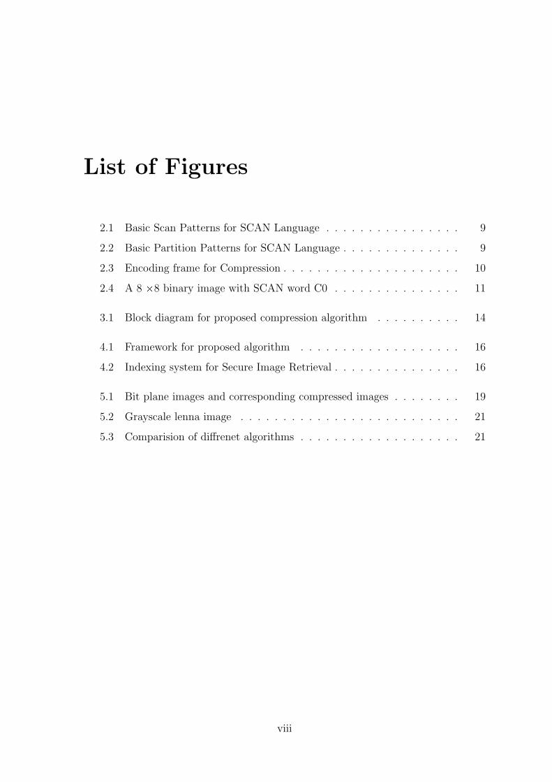
List of Figures
2.1 Basic Scan Patterns for SCAN Language . . . . . . . . . . . . . . . . 9
2.2 Basic Partition Patterns for SCAN Language . . . . . . . . . . . . . . 9
2.3 Encoding frame for Compression . . . . . . . . . . . . . . . . . . . . . 10
2.4 A 8 Ö8 binary image with SCAN word C0 . . . . . . . . . . . . . . . 11
3.1 Block diagram for proposed compression algorithm . . . . . . . . . . 14
4.1 Framework for proposed algorithm . . . . . . . . . . . . . . . . . . . 16
4.2 Indexing system for Secure Image Retrieval . . . . . . . . . . . . . . . 16
5.1 Bit plane images and corresponding compressed images . . . . . . . . 19
5.2 Grayscale lenna image . . . . . . . . . . . . . . . . . . . . . . . . . . 21
5.3 Comparision of diffrenet algorithms . . . . . . . . . . . . . . . . . . . 21
viii
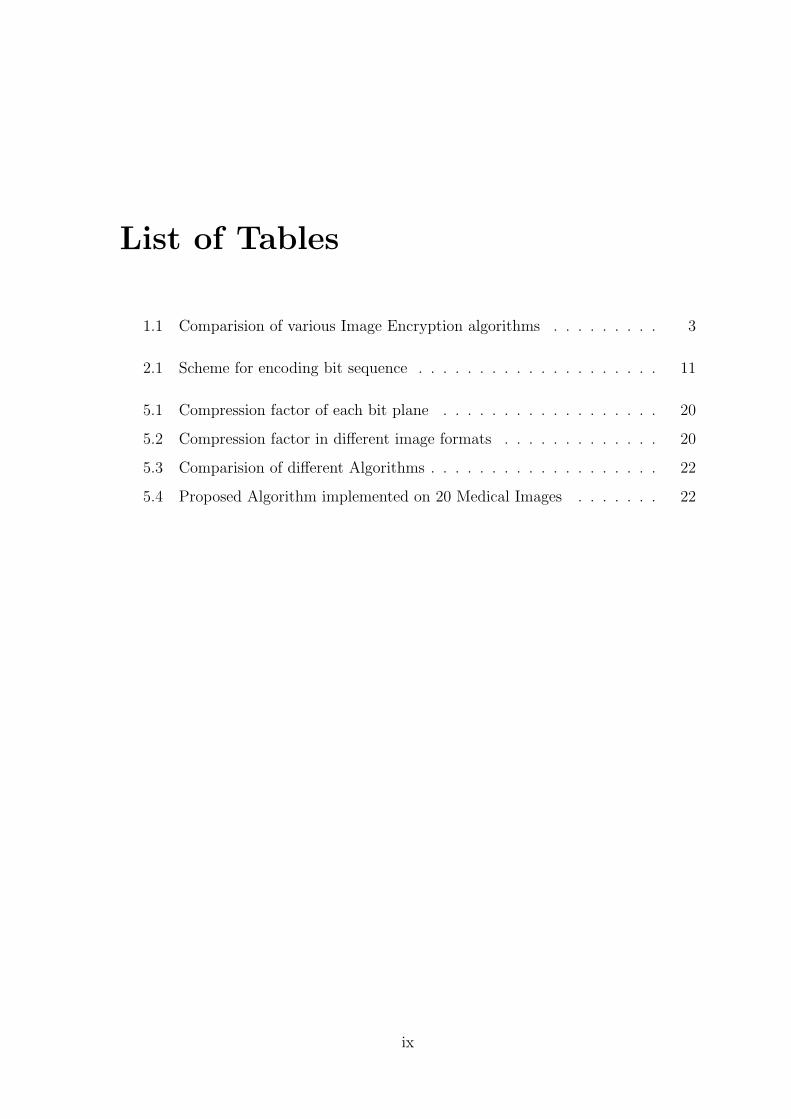
List of Tables
1.1 Comparision of various Image Encryption algorithms . . . . . . . . . 3
2.1 Scheme for encoding bit sequence . . . . . . . . . . . . . . . . . . . . 11
5.1 Compression factor of each bit plane . . . . . . . . . . . . . . . . . . 20
5.2 Compression factor in different image formats . . . . . . . . . . . . . 20
5.3 Comparision of different Algorithms . . . . . . . . . . . . . . . . . . . 22
5.4 Proposed Algorithm implemented on 20 Medical Images . . . . . . . 22
ix
Chapter 1
Introduction
Medical images include information about human body which are used for different
purposes such as surgical and diagnostic plans. Imaging devices improve everyday and
generate more data per patient. In the field of profiling patients data, medical images
need long-term storage. Also, we need to transfer the medical image files in the net-
work which requires high bandwidth. Here the need of compression is realized. Thus,
compression of medical images is used in the applications such as profiling patients
data and transmission systems. As per the importance of medical images, lossless
or near-lossless compression is preferred. Therefore, images need compression and
compression ratio is important. However, in real time processes such as telemedicine
and online diagnosis systems which need hardware implementation, simplicity of com-
pression algorithm plays an important role. It can accelerate computation process.
Further, security is also a matter of concern in case of medical images where the
privacy of patient records has to be done.
1.1 Objective
Addressing the concerns mentioned earlier we present a framework that directly deals
with the requirements using a new methodology and helps us to build a global clinical
storage adopting client-server architecture. In the framewrok, we present:
� A lossless compression technique with improved compression factor.
� An approach for the secure stoarge of medical images.
1
1.2 Image Compression Introduction
� An indexing mechanism to access to secure images stored in a remote server
from the local site
The focus is constrained to only gray scale images considering most of images gen-
erated from different modalities of medical equipments to be gray scale. In this
framework, the indexing mechanism for the retrieval of secure images is described
using Quick Response (QR) code. The purpose of using QR codes is to hold the data
in a compact format and easily access in the secure image database.
1.2 Image Compression
Image compression is the application of data compression and is a technique of reduc-
ing the redundancies in image and represents it in shorter manner. Image compression
can be lossy or lossless. There are both lossy as well as lossless compression schemes.
Depending upon the requirement we chose different techniques. For high value images
such as medical images where loss of critical information is not acceptable, lossless or
visually lossless compression is preferred.
JPEG is a very famous ISO/ITU-T standard that was created in the late 1980s.
Lossless JPEG is one of the several JPEG standards.In lossless mode, the image is
transformed by differential pulse code modulation (DPCM), and then Huffman is
applied for encoding. DPCM is based on predicting the image pixels from the neigh-
boring pixel by a specific equation and calculating the error of prediction.
JPEG-LS standard of coding still images provides lossless and near-lossless compres-
sion. The baseline system or the lossless scheme is achieved by adaptive prediction,
context modeling, and Golomb coding.
JPEG2000 is based on the discrete wavelet transform (DWT), scalar quantization,
context modeling, arithmetic coding, and post-compression rate allocation. JPEG2000
works well and gives a good compression ratio especially for high-detail images, be-
cause it analyzes the details and the approximation in the transformation step and
2
1.3 Image Security Introduction
decorrelates them. However, JPEG2000 has high computational complexity.
1.3 Image Security
With the fast progression of data exchange in electronic way, information security is
becoming more important in data storage and transmission. Because of widely using
images in industrial process, it is important to protect the confidential image data
from unauthorized access. Image encryption has applications in internet communi-
cation, multimedia systems, medical imaging, telemedicine, military communication,
etc.Images are different from text. Although we may use the traditional cryptosys-
tems to encrypt images directly, it is not a good idea for two reasons. One is that the
image size is almost always much greater than that of text. Therefore, the traditional
cryptosystems need much time to directly encrypt the image data. The other problem
is that the decrypted text must be equal to the original text. However, this require-
ment is not necessary for image data. Due to the characteristic of human perception,
a decrypted image containing small distortion is usually acceptable.
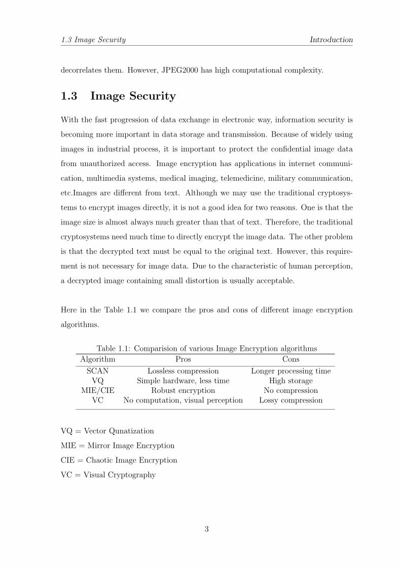
Here in the Table 1.1 we compare the pros and cons of different image encryption
algorithms.
Table 1.1: Comparision of various Image Encryption algorithms
Algorithm Pros Cons
SCAN Lossless compression Longer processing timeVQ Simple hardware, less time High storage
MIE/CIE Robust encryption No compressionVC No computation, visual perception Lossy compression
VQ = Vector Qunatization
MIE = Mirror Image Encryption
CIE = Chaotic Image Encryption
VC = Visual Cryptography
3
1.4 Medical Imaging Introduction
1.4 Medical Imaging
Medical imaging is the technique and process used to create images of the human
body (or parts and function thereof) for clinical purposes. It is often perceived to
designate the set of techniques that noninvasively produce images of the internal as-
pect of the body. In this restricted sense, medical imaging can be seen as the solution
of mathematical inverse problems. This means that cause (the properties of living
tissue) is inferred from effect (the observed signal).
Medical imaging techniques produce very large amounts of data, especially from CT,
MRI and PET modalities. As a result, storage and communications of electronic im-
age data are prohibitive without the use of compression. JPEG 2000 is the state-of-
the-art image compression DICOM standard for storage and transmission of medical
images. The cost and feasibility of accessing large image data sets over low or various
bandwidths are further addressed by use of another DICOM standard, called JPIP,
to enable efficient streaming of the JPEG 2000 compressed image data.
There has been growing trend to migrate from PACS to a Cloud Based RIS. A recent
article by Applied Radiology said, ”As the digital-imaging realm is embraced across
the healthcare enterprise, the swift transition from terabytes to petabytes of data
has put radiology on the brink of information overload. Cloud computing offers the
imaging department of the future the tools to manage data much more intelligently.”
1.5 Quick Response Code
The QR code was a kind of two dimensional barcode, and developed with a main
objective of ”Code read easily for the reader” in 1994 by Denso wave.
Bar codes have become widely popular because of their reading speed, accuracy, and
superior functionality characteristics. As bar codes became popular and their conve-
nience universally recognized, the market began to call for codes capable of storing
more information, more character types, and that could be printed in a smaller space.
4
1.5 Quick Response Code Introduction
QR Code provides the following features compared with conventional bar codes:
• High Capacity Encoding of Data
• Small Printout Size
• Kanji and Kana Capability
• Dirt and Damage Resistant
• Readable from any direction in 360
• Structured Append Feature
QR Code is capable of handling all types of data, such as numeric and alphabetic
characters, Kanji, Kana, Hiragana, symbols, binary, and control codes. Up to 7,089
characters can be encoded in one symbol. The symbol versions of QR Code range from
Version 1 to Version 40. Each version has a different module configuration or number
of modules. Modules commence with Version 1 (21 Ö21 modules) up to Version 40
(177 Ö177 modules). Each higher version number comprises 4 additional modules per
side.
Although initially used to track parts in vehicle manufacturing, QR Codes are now
(as of 2012) used over a much wider range of applications which are mentioned as
follows:
• Commercial tracking
• Entertainment and Transport ticketing
• Product/Loyalty marketing (examples: mobile couponing where a company’s
discounted and per cent discount can be captured using a QR Code decoder
which is a mobile app.
5
1.6 Organization of the Thesis Introduction
• Storing a company’s information such as address and related information along-
side its alpha-numeric text data as can be seen in Yellow Pages directory.
• Storing personal information for use by government. An example of this is
Philippines National Bureau of Investigation (NBI) where NBI clearances now
come with a QR Code.
• Mobile tagging, Users may receive text, add a vCard contact to their device,
open a Uniform Resource Identifier (URI), or compose an e-mail or text message
after scanning QR Codes.
QR Codes storing addresses and Uniform Resource Locators (URLs) may appear in
magazines, on signs, on buses, on business cards, or on almost any object about which
users might need information. Users with a camera phone equipped with the correct
reader application can scan the image of the QR Code to display text, contact in-
formation, connect to a wireless network, or open a web page in the mobile browser.
This act of linking from physical world objects is termed as hard linking or object
hyperlinking.
ZXing (pronounced ”zebra crossing”) is an open-source, multi-format 1D/2D barcode
image processing library implemented in Java, with ports to other languages. Its
focus is on using the built-in camera on mobile phones to scan and decode barcodes
on the device, without communicating with a server.
1.6 Organization of the Thesis
This thesis is organized as follow. Our compression method, its structure and speci-
fications are presented in Chapter 2. Further, Chapter 3 presents the proposed algo-
rithm on basis of which we construct a framework subsequently presented in Chapter
4. provides Experimental Results and analysis have been reviewed in Chapter 5.
Finally, Capter 6 gives concluding remarks and scope for future work.
6
Chapter 2
SCAN based Language
The SCAN is a formal language based on two dimensional spatial accessing method-
ologies which can represent and generate a large number of wide variety of scanning
paths or space filling curves easily. There are a family of formal languages such as
Simple SCAN, Extended SCAN, and Generalized SCAN, each of which can represent
and generate a specific set of scanning paths.
The SCAN methodology compresses a given binary image, by specifying a scanning
path of the image in an encoded form, and by specifying the bit sequence along the
scanning path in an encoded form. Note that a scanning path of an image is simply
an order in which each pixel of the image is accessed exactly once. At the core of
the compression method is the algorithm which determines a near optimal or a good
scanning path which minimizes the total number of bits needed to represent the en-
coded scanning path and the encoded bit sequence along the scanning path. A given
gray-scale image can be compressed by slicing each bit plane.
A scanning of a two dimensional array Pmn = p(i, j) : 1 ≤ i ≤ m, 1 ≤ j ≤ n is a bijec-
tive function from Pmn to the set {1, 2, mn-1, mn}.
7
2.1 Definition of Compression specific SCAN SCAN based Language
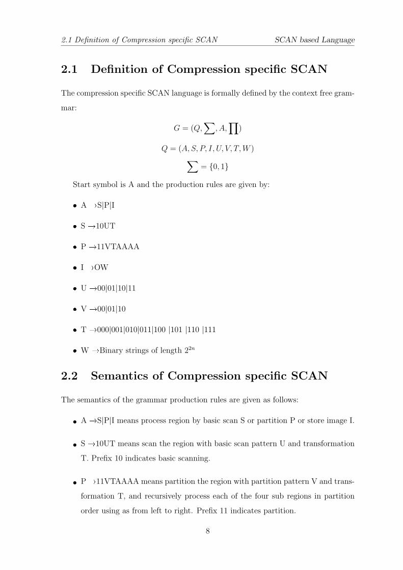
2.1 Definition of Compression specific SCAN
The compression specific SCAN language is formally defined by the context free gram-
mar:
G = (Q,∑
, A,∏
)
Q = (A, S, P, I, U, V, T,W )∑= {0, 1}
Start symbol is A and the production rules are given by:
� A �S|P|I
� S �10UT
� P �11VTAAAA
� I �OW
� U �00|01|10|11
� V �00|01|10
� T �000|001|010|011|100 |101 |110 |111
� W �Binary strings of length 22n
2.2 Semantics of Compression specific SCAN
The semantics of the grammar production rules are given as follows:
• A �S|P|I means process region by basic scan S or partition P or store image I.
• S �10UT means scan the region with basic scan pattern U and transformation
T. Prefix 10 indicates basic scanning.
• P�11VTAAAA means partition the region with partition pattern V and trans-
formation T, and recursively process each of the four sub regions in partition
order using as from left to right. Prefix 11 indicates partition.
8
2.2 Semantics of Compression specific SCAN SCAN based Language
• I �OW means store the original image of the region. Prefix 0 indicates storing
image region.
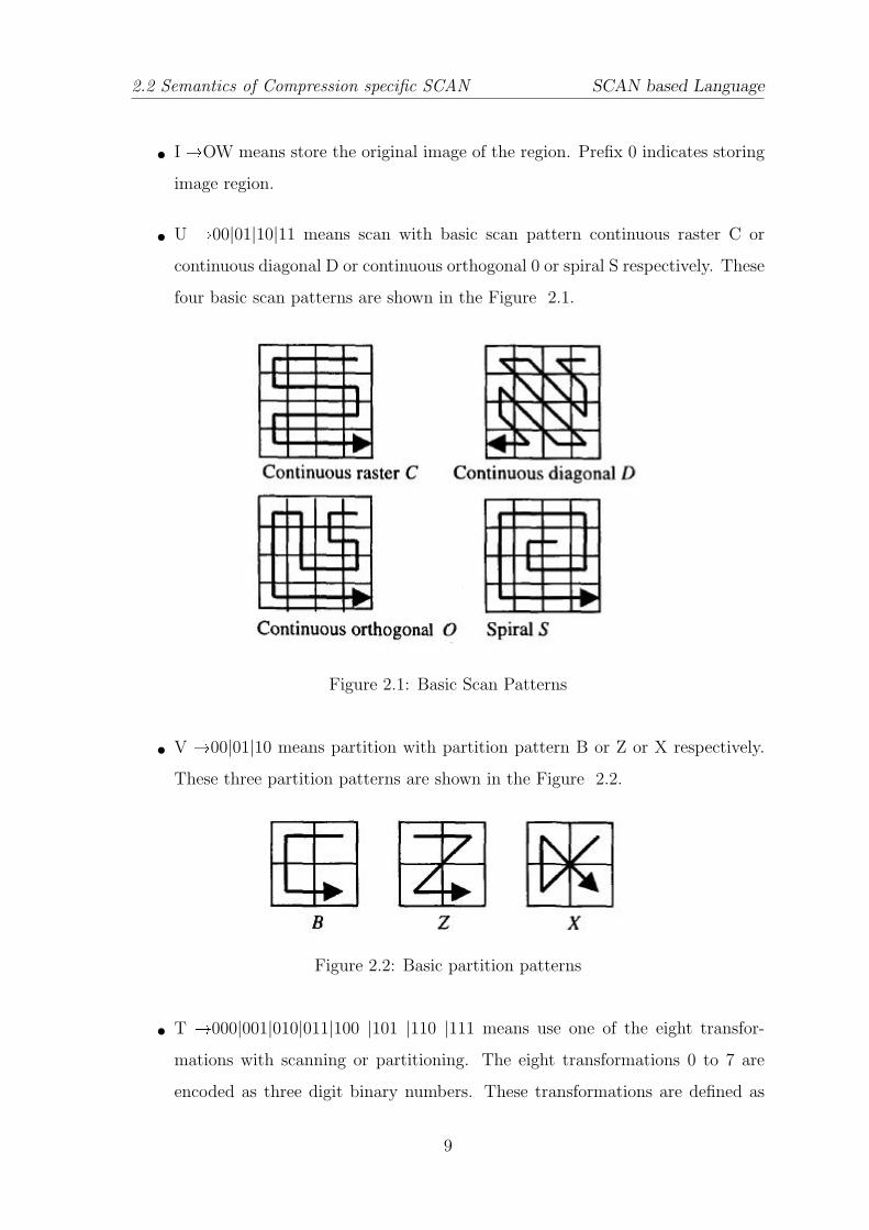
• U �00|01|10|11 means scan with basic scan pattern continuous raster C or
continuous diagonal D or continuous orthogonal 0 or spiral S respectively. These
four basic scan patterns are shown in the Figure 2.1.
Figure 2.1: Basic Scan Patterns
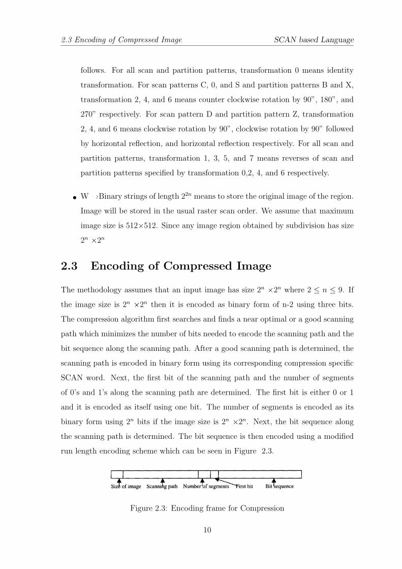
• V �00|01|10 means partition with partition pattern B or Z or X respectively.
These three partition patterns are shown in the Figure 2.2.
Figure 2.2: Basic partition patterns
• T �000|001|010|011|100 |101 |110 |111 means use one of the eight transfor-
mations with scanning or partitioning. The eight transformations 0 to 7 are
encoded as three digit binary numbers. These transformations are defined as
9
2.3 Encoding of Compressed Image SCAN based Language
follows. For all scan and partition patterns, transformation 0 means identity
transformation. For scan patterns C, 0, and S and partition patterns B and X,
transformation 2, 4, and 6 means counter clockwise rotation by 90”, 180”, and
270” respectively. For scan pattern D and partition pattern Z, transformation
2, 4, and 6 means clockwise rotation by 90”, clockwise rotation by 90” followed
by horizontal reflection, and horizontal reflection respectively. For all scan and
partition patterns, transformation 1, 3, 5, and 7 means reverses of scan and
partition patterns specified by transformation 0,2, 4, and 6 respectively.
• W�Binary strings of length 22n means to store the original image of the region.
Image will be stored in the usual raster scan order. We assume that maximum
image size is 512Ö512. Since any image region obtained by subdivision has size
2n Ö2n
2.3 Encoding of Compressed Image
The methodology assumes that an input image has size 2n Ö2n where 2 ≤ n ≤ 9. If
the image size is 2n Ö2n then it is encoded as binary form of n-2 using three bits.
The compression algorithm first searches and finds a near optimal or a good scanning
path which minimizes the number of bits needed to encode the scanning path and the
bit sequence along the scanning path. After a good scanning path is determined, the
scanning path is encoded in binary form using its corresponding compression specific
SCAN word. Next, the first bit of the scanning path and the number of segments
of 0’s and 1’s along the scanning path are determined. The first bit is either 0 or 1
and it is encoded as itself using one bit. The number of segments is encoded as its
binary form using 2n bits if the image size is 2n Ö2n. Next, the bit sequence along
the scanning path is determined. The bit sequence is then encoded using a modified
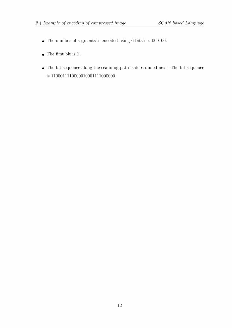
run length encoding scheme which can be seen in Figure 2.3.
Figure 2.3: Encoding frame for Compression
10
2.4 Example of encoding of compressed image SCAN based Language
Table 2.1: Scheme for encoding bit sequence
Segment size Low Limit Prefix Bits used to encode segment size Total bits
1-4 1 0 2 35-12 5 10 3 513-28 13 110 4 729-60 29 1110 5 961-316 61 11110 8 13317-1340 317 111110 10 16
1341-(218-1) 1341 111111 18 24
2.4 Example of encoding of compressed image
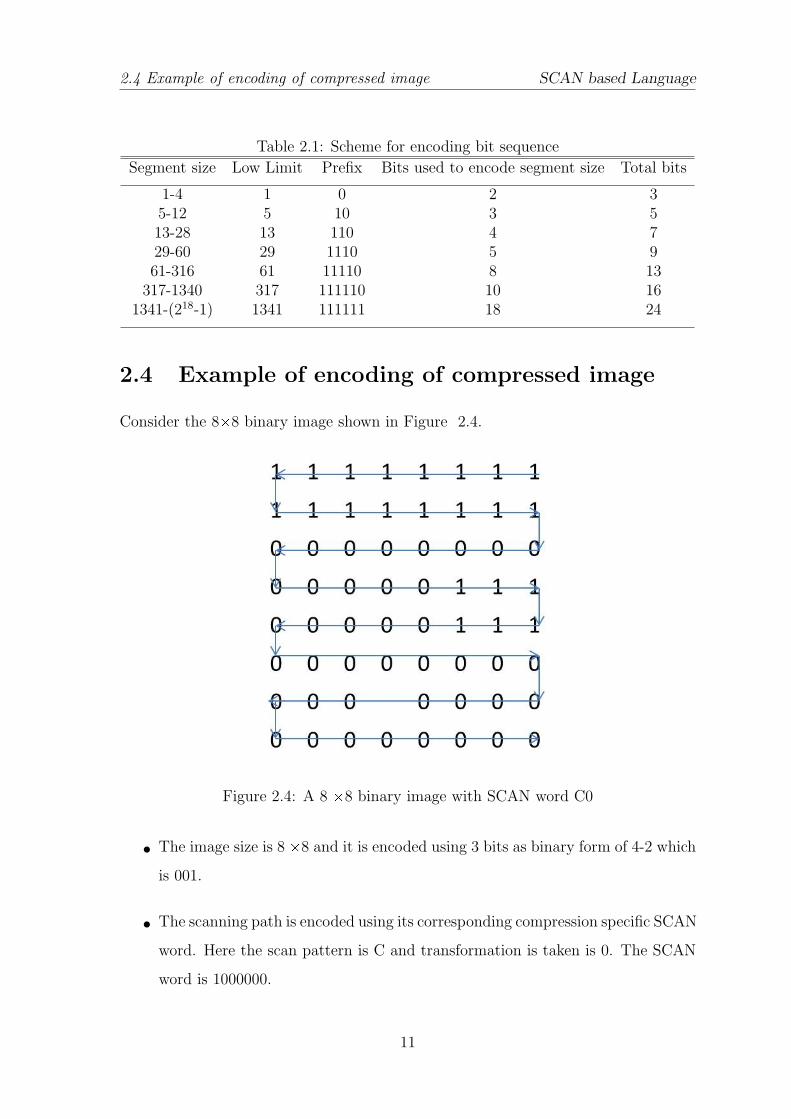
Consider the 8Ö8 binary image shown in Figure 2.4.
Figure 2.4: A 8 Ö8 binary image with SCAN word C0
• The image size is 8 Ö8 and it is encoded using 3 bits as binary form of 4-2 which
is 001.
• The scanning path is encoded using its corresponding compression specific SCAN
word. Here the scan pattern is C and transformation is taken is 0. The SCAN
word is 1000000.
11
2.4 Example of encoding of compressed image SCAN based Language
• The number of segments is encoded using 6 bits i.e. 000100.
• The first bit is 1.
• The bit sequence along the scanning path is determined next. The bit sequence
is 1100011110000010001111000000.
12
Chapter 3
Compression and Decompression
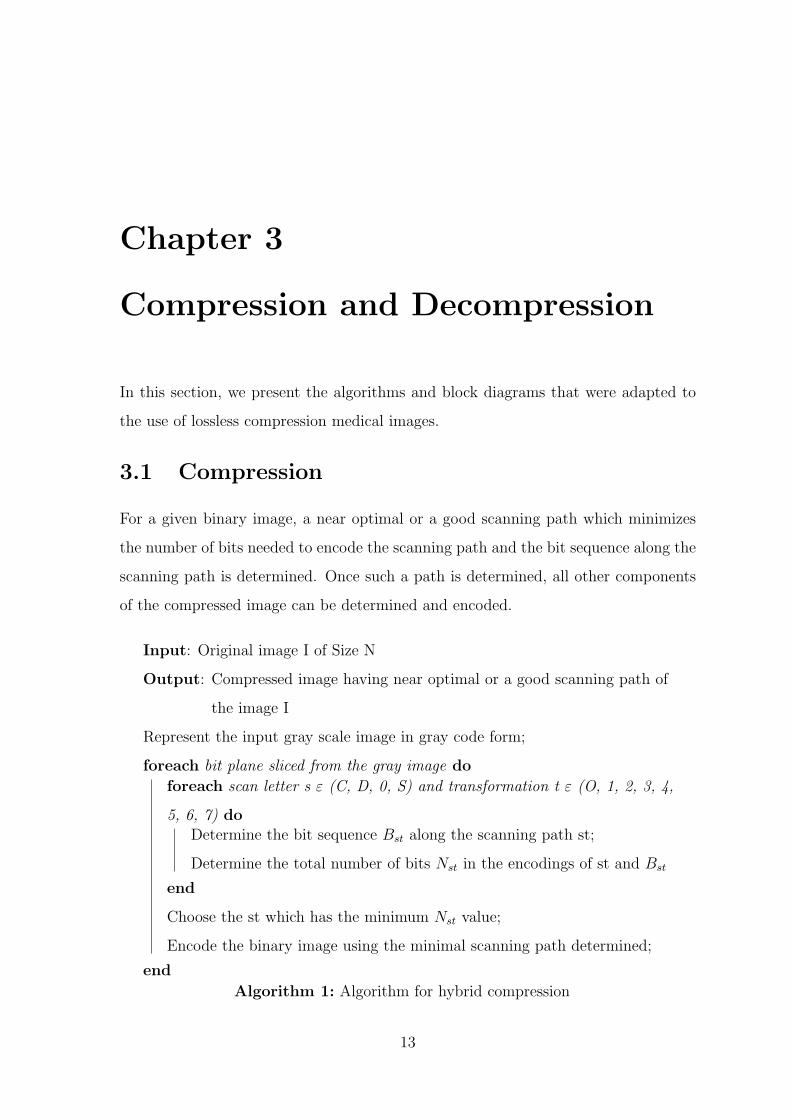
In this section, we present the algorithms and block diagrams that were adapted to
the use of lossless compression medical images.
3.1 Compression
For a given binary image, a near optimal or a good scanning path which minimizes
the number of bits needed to encode the scanning path and the bit sequence along the
scanning path is determined. Once such a path is determined, all other components
of the compressed image can be determined and encoded.
Input: Original image I of Size N
Output: Compressed image having near optimal or a good scanning path of
the image I
Represent the input gray scale image in gray code form;
foreach bit plane sliced from the gray image do
foreach scan letter s ε (C, D, 0, S) and transformation t ε (O, 1, 2, 3, 4,
5, 6, 7) doDetermine the bit sequence Bst along the scanning path st;
Determine the total number of bits Nst in the encodings of st and Bst
end
Choose the st which has the minimum Nst value;
Encode the binary image using the minimal scanning path determined;
end
Algorithm 1: Algorithm for hybrid compression
13
3.2 Decompression Compression and Decompression
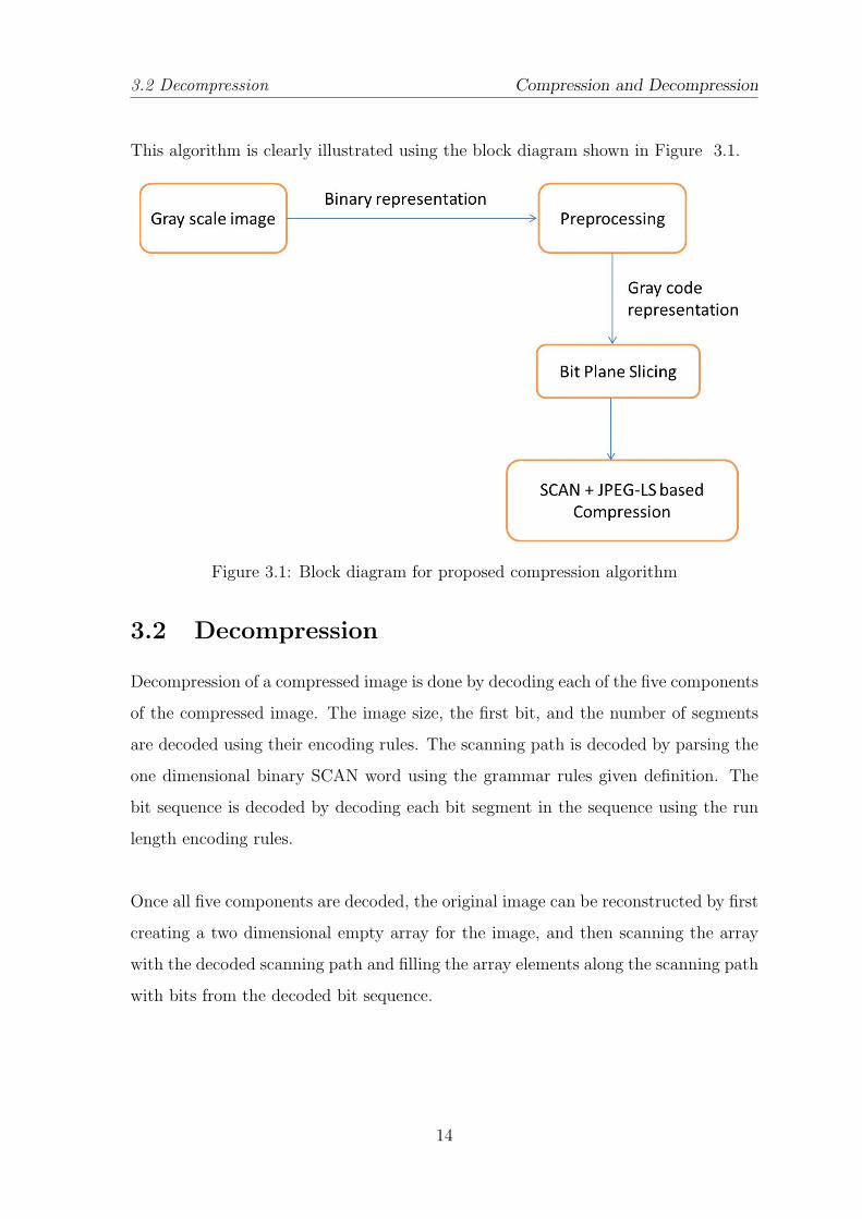
This algorithm is clearly illustrated using the block diagram shown in Figure 3.1.
Figure 3.1: Block diagram for proposed compression algorithm
3.2 Decompression
Decompression of a compressed image is done by decoding each of the five components
of the compressed image. The image size, the first bit, and the number of segments
are decoded using their encoding rules. The scanning path is decoded by parsing the
one dimensional binary SCAN word using the grammar rules given definition. The
bit sequence is decoded by decoding each bit segment in the sequence using the run
length encoding rules.
Once all five components are decoded, the original image can be reconstructed by first
creating a two dimensional empty array for the image, and then scanning the array
with the decoded scanning path and filling the array elements along the scanning path
with bits from the decoded bit sequence.
14
Chapter 4
Constructing the Framework
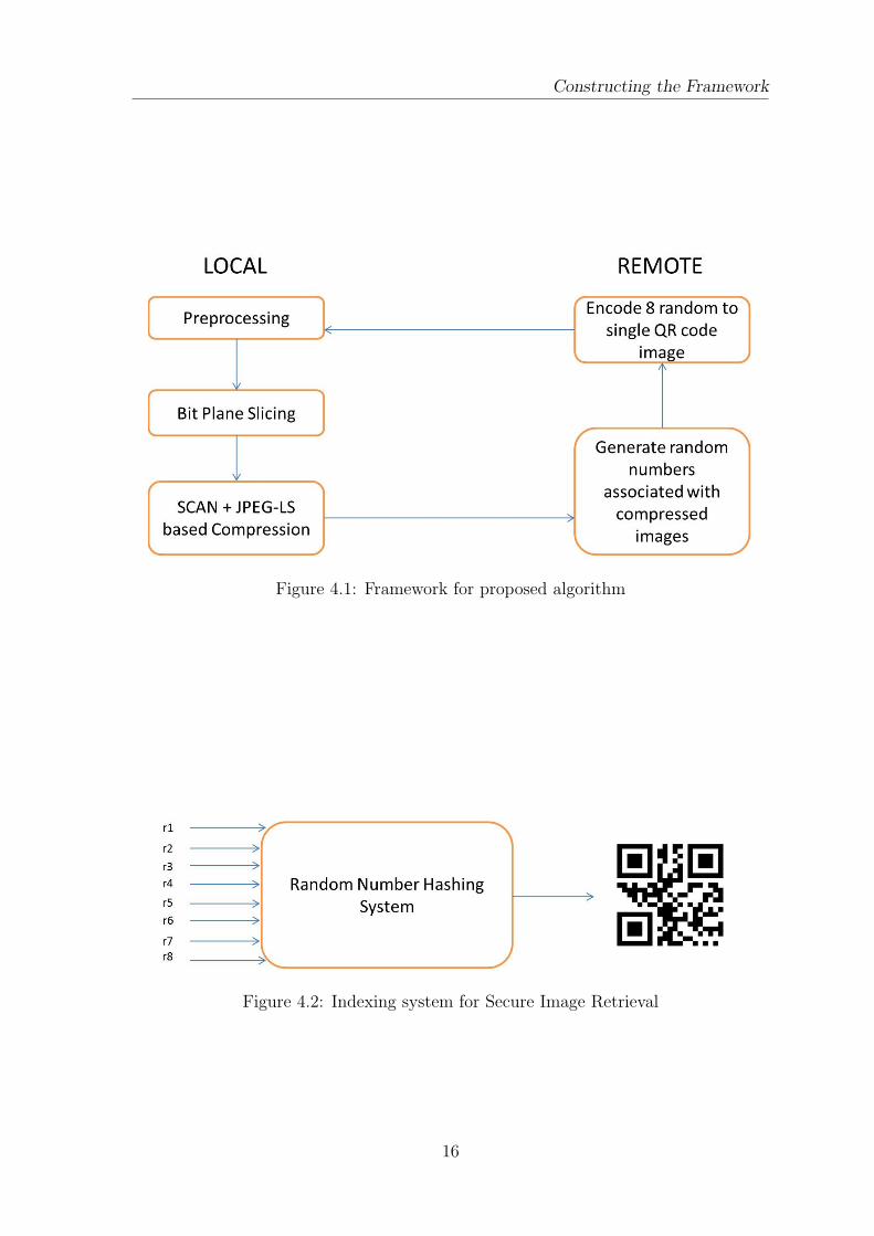
Until now, we have discuessed the lossless compression procedure using SCAN lan-
guage which ultimately uses the RLE algorithm. After the compression has been
done, the secure storage is proposed in the framework. It uses the concept of divsion
of knowledge to achieve security i.e. It stores the gray scale image (8 bits/pixel) into 8
bit plane compressed images. The total information can be obtained only by fetching
all 8 bit plane compressed images, decompressing all of them and then reconstructing
back to gray scale image. The framework has been illustarted in the block diagram
shown in Figure 4.1. So the compressed images are stored in the remote site where
the local site would be able to retrieve to it. To solve this requirement QRcode is
constructed generating a random number from each bit plane image and combning
8 random numbers corresponding to a gray scale image into a single QR code which
is demonstrated in the Figure 4.2. The random number genration can be message
dependent or independent as per the user’s requirement. The genaration of perfect
random numbers is beyond the scope of this thesis.
15
Constructing the Framework
Figure 4.1: Framework for proposed algorithm
Figure 4.2: Indexing system for Secure Image Retrieval
16
Chapter 5
Results and Analysis
The proposed algorithm was implemented on software using MATLAB R2011a. For
comparision purpose we have taken twenty gray scale images(8 bits/pixel) and their
corresponding compression and secure storage has been achieved. First we match the
time complexitity of existing and proposed algorithm before proceeding further.
5.1 Time Complexity
• For the existing algorithm
T (n) = 8 ∗ (32 ∗ cp(n) + fm(n))
• For the proposed algorithm
T (n) = 4 ∗ (pp(n) + 32 ∗ cp(n) + fm(n)) + 4 ∗ J(n)
n = image size
T(n) = Time complexity
cp(n) = Comparison time
fm(n) = Frame encoding time
J(n) = Time required in JPEG-LS
pp(n) = Preprocesing time
17
5.2 Output Results Results and Analysis
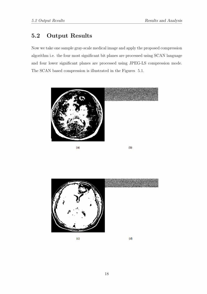
5.2 Output Results
Now we take one sample gray-scale medical image and apply the proposed compression
algorithm i.e. the four most significant bit planes are processed using SCAN language
and four lower significant planes are processed using JPEG-LS compression mode.
The SCAN based compression is illustrated in the Figures 5.1.
18
5.2 Output Results Results and Analysis
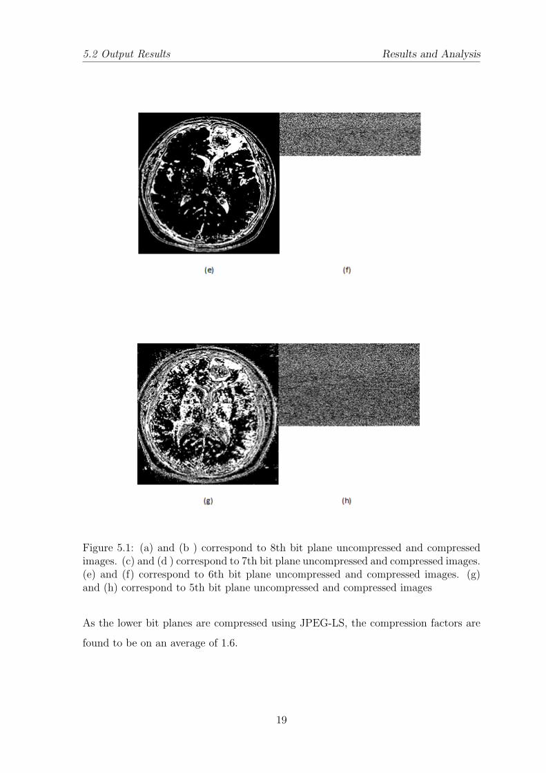
Figure 5.1: (a) and (b ) correspond to 8th bit plane uncompressed and compressedimages. (c) and (d ) correspond to 7th bit plane uncompressed and compressed images.(e) and (f) correspond to 6th bit plane uncompressed and compressed images. (g)and (h) correspond to 5th bit plane uncompressed and compressed images
As the lower bit planes are compressed using JPEG-LS, the compression factors are
found to be on an average of 1.6.
19
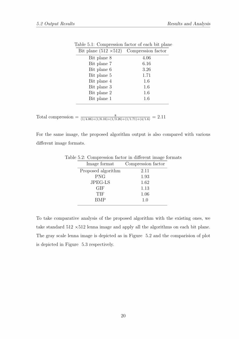
5.2 Output Results Results and Analysis
Table 5.1: Compression factor of each bit plane
Bit plane (512 Ö512) Compression factor
Bit plane 8 4.06Bit plane 7 6.16Bit plane 6 3.26Bit plane 5 1.71Bit plane 4 1.6Bit plane 3 1.6Bit plane 2 1.6Bit plane 1 1.6
Total compression = 8(1/4.06)+(1/6.16)+(1/3.26)+(1/1.71)+(4/1.6)
= 2.11
For the same image, the proposed algorithm output is also compared with various
different image formats.
Table 5.2: Compression factor in different image formats
Image format Compression factor
Proposed algorithm 2.11PNG 1.93
JPEG-LS 1.62GIF 1.13TIF 1.06BMP 1.0
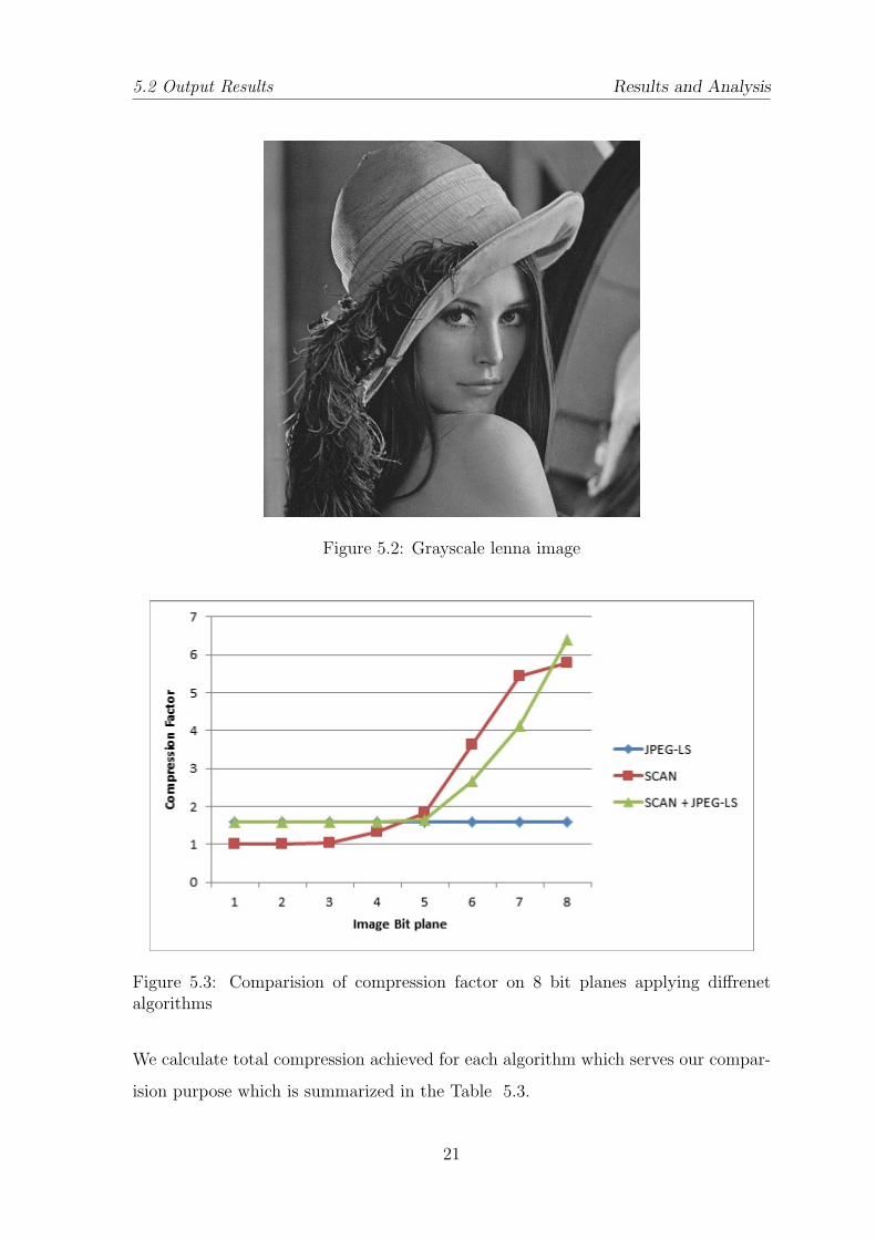
To take comparative analysis of the proposed algorithm with the existing ones, we
take standard 512 Ö512 lenna image and apply all the algorithms on each bit plane.
The gray scale lenna image is depicted as in Figure 5.2 and the comparision of plot
is depicted in Figure 5.3 respectively.
20
5.2 Output Results Results and Analysis
Figure 5.2: Grayscale lenna image
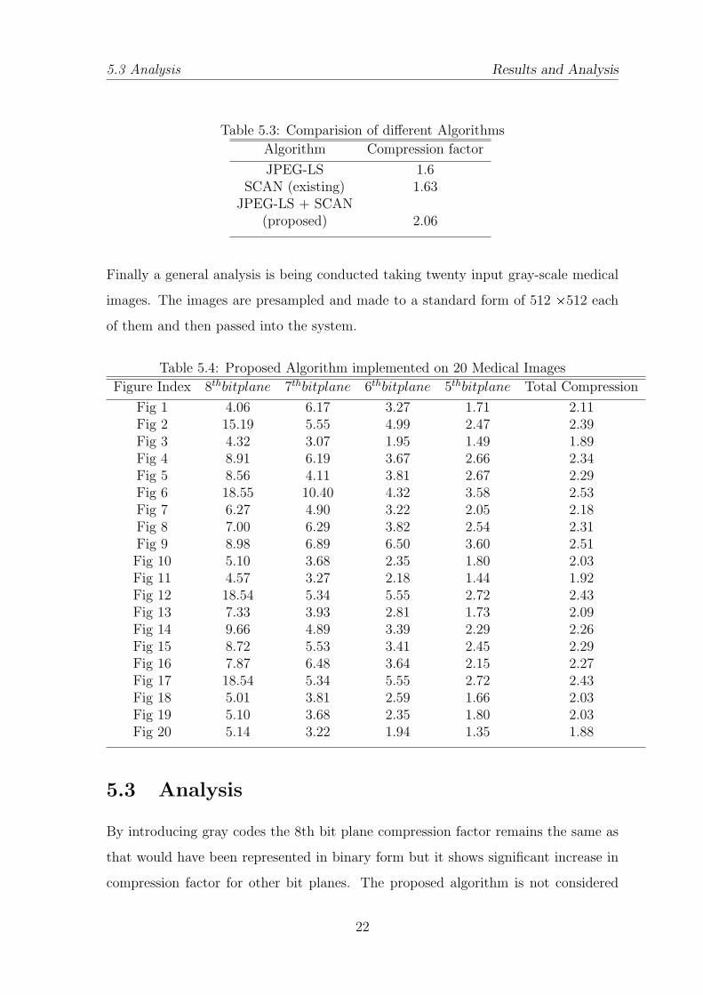
Figure 5.3: Comparision of compression factor on 8 bit planes applying diffrenetalgorithms
We calculate total compression achieved for each algorithm which serves our compar-
ision purpose which is summarized in the Table 5.3.
21
5.3 Analysis Results and Analysis
Table 5.3: Comparision of different Algorithms
Algorithm Compression factor
JPEG-LS 1.6SCAN (existing) 1.63
JPEG-LS + SCAN(proposed) 2.06
Finally a general analysis is being conducted taking twenty input gray-scale medical
images. The images are presampled and made to a standard form of 512 Ö512 each
of them and then passed into the system.
Table 5.4: Proposed Algorithm implemented on 20 Medical Images
Figure Index 8thbitplane 7thbitplane 6thbitplane 5thbitplane Total Compression
Fig 1 4.06 6.17 3.27 1.71 2.11Fig 2 15.19 5.55 4.99 2.47 2.39Fig 3 4.32 3.07 1.95 1.49 1.89Fig 4 8.91 6.19 3.67 2.66 2.34Fig 5 8.56 4.11 3.81 2.67 2.29Fig 6 18.55 10.40 4.32 3.58 2.53Fig 7 6.27 4.90 3.22 2.05 2.18Fig 8 7.00 6.29 3.82 2.54 2.31Fig 9 8.98 6.89 6.50 3.60 2.51Fig 10 5.10 3.68 2.35 1.80 2.03Fig 11 4.57 3.27 2.18 1.44 1.92Fig 12 18.54 5.34 5.55 2.72 2.43Fig 13 7.33 3.93 2.81 1.73 2.09Fig 14 9.66 4.89 3.39 2.29 2.26Fig 15 8.72 5.53 3.41 2.45 2.29Fig 16 7.87 6.48 3.64 2.15 2.27Fig 17 18.54 5.34 5.55 2.72 2.43Fig 18 5.01 3.81 2.59 1.66 2.03Fig 19 5.10 3.68 2.35 1.80 2.03Fig 20 5.14 3.22 1.94 1.35 1.88
5.3 Analysis
By introducing gray codes the 8th bit plane compression factor remains the same as
that would have been represented in binary form but it shows significant increase in
compression factor for other bit planes. The proposed algorithm is not considered
22
5.3 Analysis Results and Analysis
beyond 5th bit plane because for most of the cases it gives a compression factor ≥
1.6 is only up to 5th bit plane. The JPEG-LS mode compression factor 1.6 is used a
threshold value.
If there is 1000 input gray scale images in the local site, then after all the execu-
tion of steps there would be 1000 QR hash codes and 8000 binary bit plane images in
the Remote site. Now for a proper matching of the input image the third person has
to fetch 8 images out of 8000 images in the remote site to make one proper image.
The no of unit operations is 4.14 Ö1026. If one unit operation takes 1µS, then total
time required will be 1020.
Well, this framework provides a better structure for lossless compression and secure
storage but with the cost of increasing time.
23
Chapter 6
Conclusion
This thesis presented a new methodology which ensures both lossless compression
and security in the case of medical gray-scale images. The proposed algorithms uses
cobine effect of SCAN and JPEG-LS techniques to produce better compression. The
drawback of the methodology is that compression-encryption takes longer time. Also
we have indexed the remote location of encrypted images using QR codes which are
stored locally and make process of accessing faster. The methodology can be made
real time through hardware implementation.
There is also many future scopes in this field. The most coomon feature in medi-
cal images is that a small region holds most significant and required information. So
instead compressing the whole image in lossless mode we can concentarte our focus on
the Region of Interest (ROI) and can adapt other high compression ratio algorithms
for the compliment region. Segmentation of medical images and then applying the
technique may also improve the system efficieny.
24
Bibliography
[1] S.S. Maniccam and N.G. Bourbakis. Scan based lossless image compression and encryption.
In Information Intelligence and Systems, 1999. Proceedings. 1999 International Conference on,
pages 490 –499, 1999.
[2] N.G. Bourbakis. Image data compression-encryption using g-scan patterns. In Systems, Man,
and Cybernetics, 1997. Computational Cybernetics and Simulation., 1997 IEEE International
Conference on, volume 2, pages 1117 –1120 vol.2, oct 1997.
[3] Rafael C. Gonzalez and Richard E. Woods. Digital Image Processing (3rd Edition). Prentice-Hall,
Inc., Upper Saddle River, NJ, USA, 2006.
[4] David Salomon. Data Compression: The Complete Reference. 2007. With contributions by
Giovanni Motta and David Bryant.
[5] Documentation, http://code.google.com/p/zxing/.
[6] Documentation, http://www.mikety.net/Articles/ImageComp/ImageComp.html.
[7] C.M. Thompson and L. Shure. Image Processing Toolbox: For Use with MATLAB;[user’s Guide].
MathWorks, 1995.
[8] Documentation, http://www.mikety.net/Articles/ImageComp/ImageComp.html.
25
Recommended