LTHLow Temperature
Merchandisers
P/N 0506146_DDecember 2010
Merchandisers
®
P/N0506146_D
IIMMPPOORRTTAANNTTKeep in store for
future reference!
Installation & Service Manual

P/N 0506146_D iii
Merchandiser must operate for 24 hours before loading product!
Regularly check merchandiser temperatures.
Do not break the cold chain. Keep products in cooler before loading into merchandiser.
These merchandisers are designed
for pre-frozen products only.
IMPORTANTKEEP IN STORE FOR FUTURE REFERENCE
Quality that sets industry standards!
12999 St. Charles Rock Road • Bridgeton, MO 63044-2483
U.S. & Canada 1-800-922-1919 • Mexico 1-800-522-1900
www.hussmann.com© 2010 Hussmann Corporation
®

ANSI DEFINITIONS . . . . . . . . . . . . . . . . . vi
INSTALLATION
NSF Certification . . . . . . . . . . . . . . . . . . . 1-1Hussmann Product Control . . . . . . . . . . . . 1-1Location . . . . . . . . . . . . . . . . . . . . . . . . . . . 1-1Shipping Damage . . . . . . . . . . . . . . . . . . . 1-1Self Contained Location . . . . . . . . . . . . . . 1-2Unloading . . . . . . . . . . . . . . . . . . . . . . . . . 1-3Exterior Loading . . . . . . . . . . . . . . . . . . . . 1-3Shipping Skid . . . . . . . . . . . . . . . . . . . . . . .1-3Model Description . . . . . . . . . . . . . . . . . . 1-4Cabinet Leveling . . . . . . . . . . . . . . . . . . . . 1-4Door Seal . . . . . . . . . . . . . . . . . . . . . . . . . . 1-5Serial Plate Location . . . . . . . . . . . . . . . . . 1-5Door Lock . . . . . . . . . . . . . . . . . . . . . . . . . 1-5Shelf Installation . . . . . . . . . . . . . . . . . . . . 1-6Lamps . . . . . . . . . . . . . . . . . . . . . . . . . . . . 1-6Door Switch . . . . . . . . . . . . . . . . . . . . . . . 1-6Stocking . . . . . . . . . . . . . . . . . . . . . . . . . . . 1-7Condensing Unit Air Flow . . . . . . . . . . . . 1-7Load Limits . . . . . . . . . . . . . . . . . . . . . . . . 1-7LTH Illustrations . . . . . . . . . . . . . . . . . . . . 1-8
ELECTRICAL / REFRIGERATION
Plug . . . . . . . . . . . . . . . . . . . . . . . . . . . . . . . 2-1Refrigeration . . . . . . . . . . . . . . . . . . . . . . . . 2-2Defrost Cycle . . . . . . . . . . . . . . . . . . . . . . . 2-2NOTES . . . . . . . . . . . . . . . . . . . . . . . . . . . 2-4
START UP / OPERATION
OPERATING SAFE-NET™ I CONTROLS
Temperature Control . . . . . . . . . . . . . . . . . 3-1Setting Safe-NET I Time . . . . . . . . . . . . . . 3-2Escape Menu . . . . . . . . . . . . . . . . . . . . . . . 3-2Safe-NET I Defrosts . . . . . . . . . . . . . . . . . 3-2Set Defrost Time (Safe-NET I) . . . . . . . . . 3-3Alarms (Safe-NET I) . . . . . . . . . . . . . . . . 3-4Sequence of Operation (Safe-NET I) . . . . 3-5
OPERATING SAFE-NET™ III CONTROLS . . . 3-6Start-Up / Operation . . . . . . . . . . . . . . . . . 3-7Alarms and Codes . . . . . . . . . . . . . . . . . . . 3-7Defrost Termination Switch . . . . . . . . . . . 3-8Manual Defrost . . . . . . . . . . . . . . . . . . . . . 3-8Temperature Adjustment . . . . . . . . . . . . . 3-9Sensor to Control Configuration . . . . . . 3-10Sequence of Operation (Safe-NET III) . 3-11Controls and Adjustments . . . . . . . . . . . . 3-12Thermostatic Expansion Valve (TEV) . . 3-13NOTES . . . . . . . . . . . . . . . . . . . . . . . . . . 3-14
MAINTENANCE
Care and Cleaning . . . . . . . . . . . . . . . . . . . 4-1Exterior Surfaces . . . . . . . . . . . . . . . . . . 4-1Interior Surfaces . . . . . . . . . . . . . . . . . . . 4-1Cleaning Shelves . . . . . . . . . . . . . . . . . . . 4-2Cleaning Condenser Coils . . . . . . . . . . . 4-2Optional Reversing Condenser Fan . . . 4-3Cleaning Wash Out Drain . . . . . . . . . . . 4-4
Tips and Trouble Shooting . . . . . . . . . . . . 4-4
SERVICE
Replacing Fluorescent Lamps . . . . . . . . . . 5-1Replacing Display Lamp . . . . . . . . . . . . . . 5-1Replacing Interior Lamps . . . . . . . . . . . . . 5-2Replacing Electronic Ballasts . . . . . . . . . . . 5-2
Table of Contents Continued on next page.
TABLE OF CONTENTS v
HUSSMANN CORPORATION • BRIDGETON, MO 63044-2483 U.S.A. LTH Merchandisers
* * * * * * * * * * * * * * * * * * * * * * * * * *ANSI Z535.5 DEFINITIONS
• DANGER – Indicate[s] a hazardoussituation which, if not avoided, willresult in death or serious injury.
• WARNING – Indicate[s] a hazardoussituation which, if not avoided, couldresult in death or serious injury.
• CAUTION – Indicate[s] a hazardoussituation which, if not avoided, couldresult in minor or moderate injury.
• NOTICE – Not related to personal injury –Indicates[s] situations, which if not avoided,could result in damage to equipment.
�
�
�
vi
APPENDIX A — TECHNICAL DATA
Part Numbers . . . . . . . . . . . . . . . . . . . . . . A-1Cross Section / Refrigeration Data . . . . . A-4Merchandiser Dimensions . . . . . . . . . . . . A-5Electrical Data . . . . . . . . . . . . . . . . . . . . . A-6LTH-8 Wiring Diagrams . . . . . . . . . . . . . A-7LTH-18 Wiring Diagrams . . . . . . . . . . . . A-8LTH-45, 68 Wiring Diagrams . . . . . . . . . A-9LTH-8 LED Wiring Diagrams . . . . . . . . A-10LTH-18 LED Wiring Diagrams . . . . . . . A-11LTH-45, 68 LED Wiring Diagrams . . . . A-12
WARRANTY
REVISION HISTORY
Revision D — December 2010Added Air Flow Drawing, Page, 1-2Added Model Description, Page, 1-3Added Serial Plate Location, Page 1-5Revised Stocking Illustrations, Page 1-7Added Sequence of Operation Diagram, Page 3-5Added Appendix A
Revision C — June 2009Added LTH-45 and LTH-68 modelsUpdated wiring diagramsAdded Safe-NET I codesAdded Safe-NET III information
Revision B — Added Safe-NET™Restructured manual; added Maintenanceinformation
Revision A —Original Issue
P/N 0506146_D U.S. & Canada 1-800-922-1919 • Mexico 1-800-522-1900 • www.hussmann.com
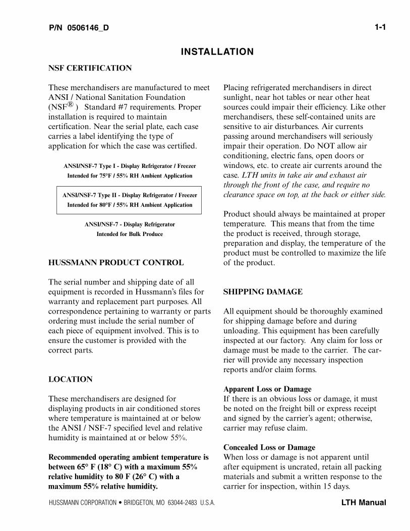
NSF CERTIFICATION
These merchandisers are manufactured to meetANSI / National Sanitation Foundation(NSF® ) Standard #7 requirements. Properinstallation is required to maintain certification. Near the serial plate, each casecarries a label identifying the type ofapplication for which the case was certified.
ANSI/NSF-7 Type I - Display Refrigerator / Freezer
Intended for 75°F / 55% RH Ambient Application
ANSI/NSF-7 Type II - Display Refrigerator / Freezer
Intended for 80°F / 55% RH Ambient Application
ANSI/NSF-7 - Display Refrigerator
Intended for Bulk Produce
HUSSMANN PRODUCT CONTROL
The serial number and shipping date of allequipment is recorded in Hussmann’s files forwarranty and replacement part purposes. Allcorrespondence pertaining to warranty or partsordering must include the serial number ofeach piece of equipment involved. This is toensure the customer is provided with the correct parts.
LOCATION
These merchandisers are designed for displaying products in air conditioned storeswhere temperature is maintained at or belowthe ANSI / NSF-7 specified level and relativehumidity is maintained at or below 55%.
Recommended operating ambient temperature isbetween 65° F (18° C) with a maximum 55% relative humidity to 80 F (26° C) with a maximum 55% relative humidity.
Placing refrigerated merchandisers in directsunlight, near hot tables or near other heatsources could impair their efficiency. Like othermerchandisers, these self-contained units aresensitive to air disturbances. Air currents passing around merchandisers will seriouslyimpair their operation. Do NOT allow air conditioning, electric fans, open doors or windows, etc. to create air currents around thecase. LTH units in take air and exhaust airthrough the front of the case, and require noclearance space on top, at the back or either side.
Product should always be maintained at proper temperature. This means that from the timethe product is received, through storage, preparation and display, the temperature of theproduct must be controlled to maximize the lifeof the product.
SHIPPING DAMAGE
All equipment should be thoroughly examinedfor shipping damage before and during unloading. This equipment has been carefullyinspected at our factory. Any claim for loss ordamage must be made to the carrier. The car-rier will provide any necessary inspectionreports and/or claim forms.
Apparent Loss or DamageIf there is an obvious loss or damage, it mustbe noted on the freight bill or express receiptand signed by the carrier’s agent; otherwise,carrier may refuse claim.
Concealed Loss or DamageWhen loss or damage is not apparent untilafter equipment is uncrated, retain all packingmaterials and submit a written response to thecarrier for inspection, within 15 days.
P/N 0506146_D 1-1
LTH Manual
INSTALLATION
HUSSMANN CORPORATION • BRIDGETON, MO 63044-2483 U.S.A.
1-1
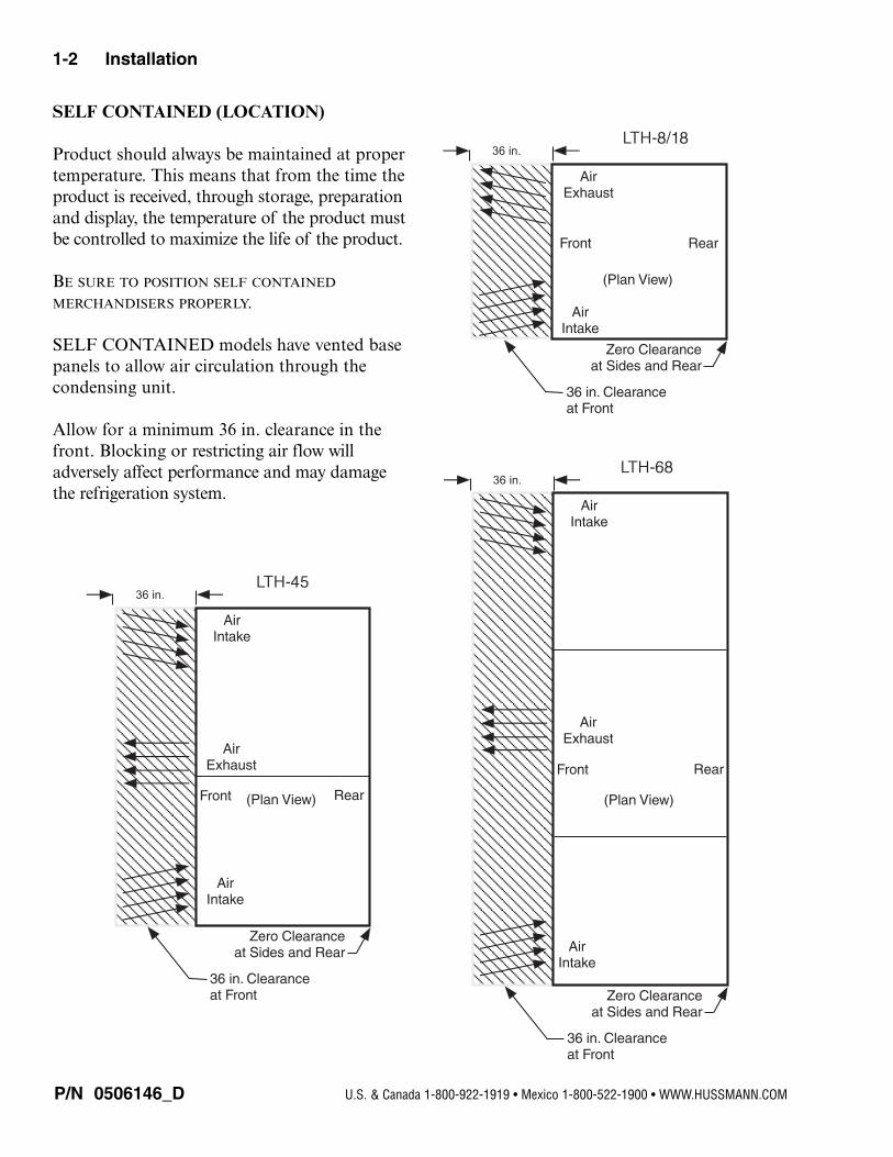
SELF CONTAINED (LOCATION)
Product should always be maintained at proper temperature. This means that from the time theproduct is received, through storage, preparationand display, the temperature of the product mustbe controlled to maximize the life of the product.
BE SURE TO POSITION SELF CONTAINED
MERCHANDISERS PROPERLY.
SELF CONTAINED models have vented basepanels to allow air circulation through the condensing unit.
Allow for a minimum 36 in. clearance in thefront. Blocking or restricting air flow willadversely affect performance and may damagethe refrigeration system.
P/N 0506146_D
1-2 Installation
U.S. & Canada 1-800-922-1919 • Mexico 1-800-522-1900 • WWW.HUSSMANN.COM
36 in.
Air Intake
Air Exhaust
Front Rear
Zero Clearance at Sides and Rear
36 in. Clearance at Front
(Plan View)
36 in.
Air Intake
Air Intake
Front Rear
Zero Clearance at Sides and Rear
36 in. Clearance at Front
(Plan View)
Air Exhaust
36 in.
Air Intake
Air Intake
Front Rear
Zero Clearance at Sides and Rear
36 in. Clearance at Front
(Plan View)
Air Exhaust
UNLOADING
Unloading from Trailer:
Lever Bar (also known as a Mule, JohnsonBar, J-Bar, Lever Dolly, or Pry Lever)
Move the merchandiser as close as possible toits permanent location and remove all packaging.Check for damage before discarding packaging.Remove all separately packed accessories such askits and shelves.
Improper handling may cause damage to themerchandiser when unloading. To avoid damage:
1. Do not drag the merchandiser out of thetrailer. Use a Johnson bar (mule).
2. Use a forklift or dolly to remove the merchandiser from the trailer.
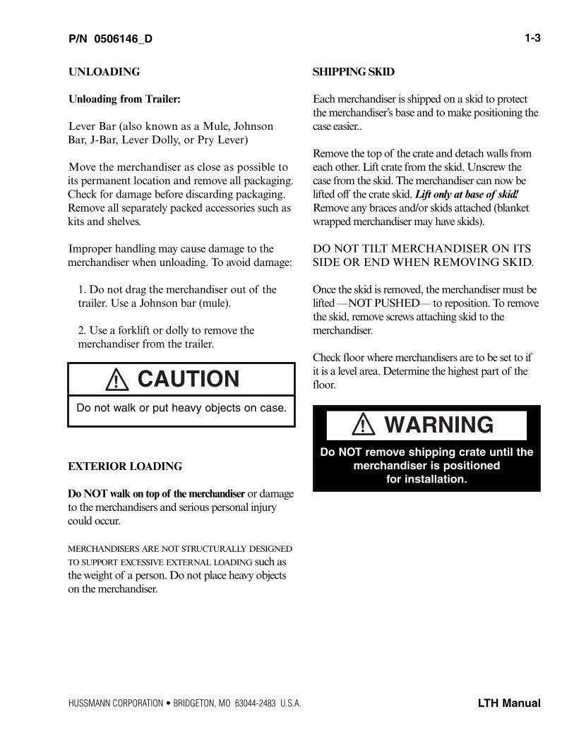
EXTERIOR LOADING
Do NOT walk on top of the merchandiser or damageto the merchandisers and serious personal injurycould occur.
MERCHANDISERS ARE NOT STRUCTURALLY DESIGNED
TO SUPPORT EXCESSIVE EXTERNAL LOADING such asthe weight of a person. Do not place heavy objectson the merchandiser.
SHIPPING SKID
Each merchandiser is shipped on a skid to protectthe merchandiser’s base and to make positioning thecase easier..
Remove the top of the crate and detach walls fromeach other. Lift crate from the skid. Unscrew thecase from the skid. The merchandiser can now belifted off the crate skid. Lift only at base of skid!Remove any braces and/or skids attached (blanketwrapped merchandiser may have skids).
DO NOT TILT MERCHANDISER ON ITSSIDE OR END WHEN REMOVING SKID.
Once the skid is removed, the merchandiser must belifted —NOT PUSHED— to reposition. To removethe skid, remove screws attaching skid to the merchandiser.
Check floor where merchandisers are to be set to ifit is a level area. Determine the highest part of thefloor.
P/N 0506146_D 1-3
LTH Manual
Do NOT remove shipping crate until themerchandiser is positioned
for installation.
WARNING!
CAUTION!Do not walk or put heavy objects on case.
HUSSMANN CORPORATION • BRIDGETON, MO 63044-2483 U.S.A.
MODEL DESCRIPTION
LTH merchandisers are low temperature self-contained cabinets, designed for pre-packagedfrozen food or products that require frozentemperatures for conservation.
Design features include:
• Self-closing glass doors• Electronic controls• CFC free-foam insulation• Lighted Sign (except LTH-8S)• Door lock• Cassette refrigeration system
Available options are:
• Reversing condenser fan motor• Buzzer alarm
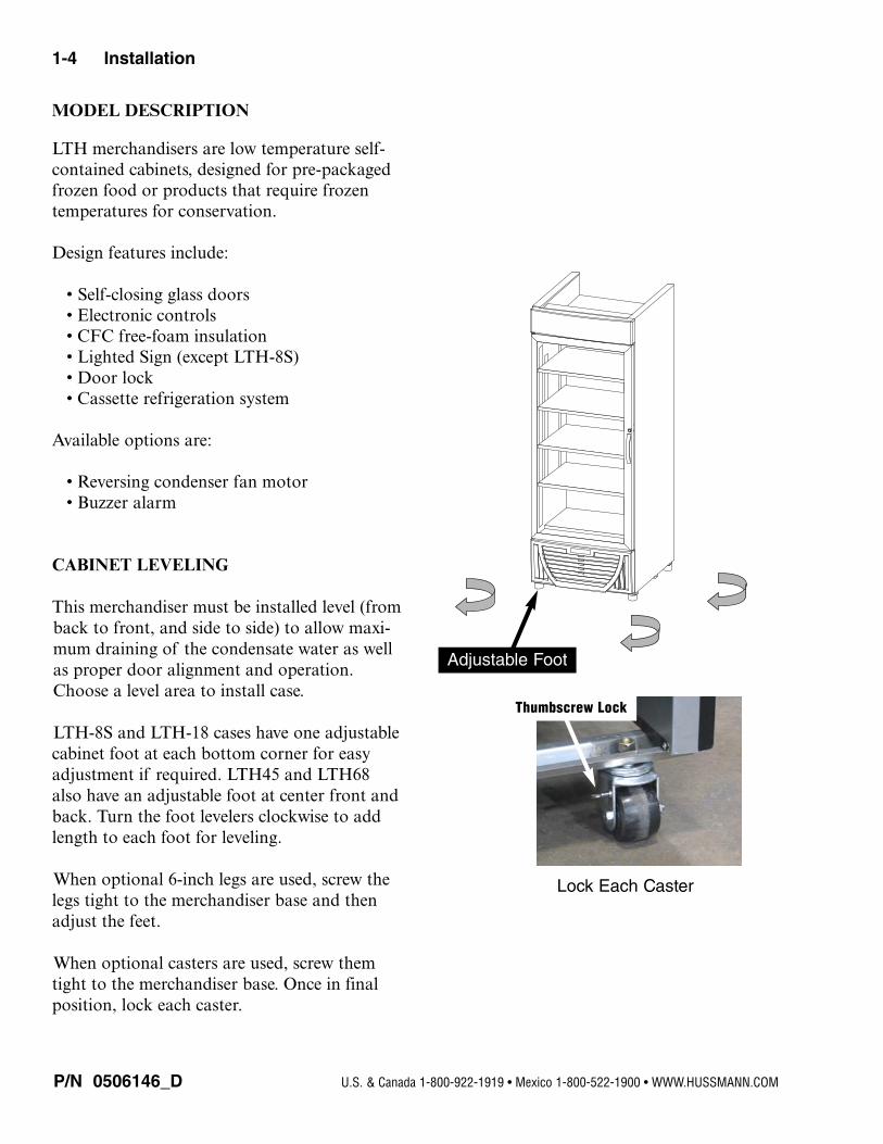
CABINET LEVELING
This merchandiser must be installed level (fromback to front, and side to side) to allow maxi-mum draining of the condensate water as wellas proper door alignment and operation.Choose a level area to install case.
LTH-8S and LTH-18 cases have one adjustable cabinet foot at each bottom corner for easyadjustment if required. LTH45 and LTH68also have an adjustable foot at center front andback. Turn the foot levelers clockwise to addlength to each foot for leveling.
When optional 6-inch legs are used, screw thelegs tight to the merchandiser base and thenadjust the feet.
When optional casters are used, screw themtight to the merchandiser base. Once in finalposition, lock each caster.
P/N 0506146_D
1-4 Installation
U.S. & Canada 1-800-922-1919 • Mexico 1-800-522-1900 • WWW.HUSSMANN.COM
Adjustable Foot
Lock Each Caster
Thumbscrew Lock
P/N 0506146_D 1-5
LTH Manual
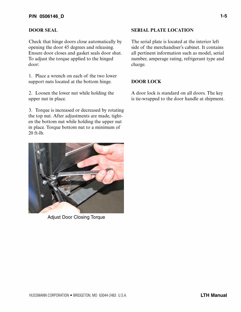
Adjust Door Closing Torque
DOOR SEAL
Check that hinge doors close automatically byopening the door 45 degrees and releasing.Ensure door closes and gasket seals door shut.To adjust the torque applied to the hingeddoor:
1. Place a wrench on each of the two lowersupport nuts located at the bottom hinge.
2. Loosen the lower nut while holding theupper nut in place.
3. Torque is increased or decreased by rotatingthe top nut. After adjustments are made, tight-en the bottom nut while holding the upper nutin place. Torque bottom nut to a minimum of20 ft-lb.
SERIAL PLATE LOCATION
The serial plate is located at the interior leftside of the merchandiser’s cabinet. It containsall pertinent information such as model, serialnumber, amperage rating, refrigerant type andcharge.
DOOR LOCK
A door lock is standard on all doors. The keyis tie-wrapped to the door handle at shipment.
HUSSMANN CORPORATION • BRIDGETON, MO 63044-2483 U.S.A.
P/N 0506146_D
1-6 Installation
U.S. & Canada 1-800-922-1919 • Mexico 1-800-522-1900 • WWW.HUSSMANN.COM
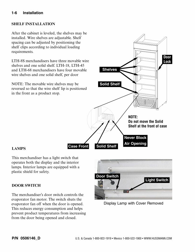
Shelves
Solid Shelf
NOTE:
Do not move the Solid
Shelf at the front of case
Display Lamp with Cover Removed
Light Switch
Solid ShelfCase Front
Door
Lock
SHELF INSTALLATION
After the cabinet is leveled, the shelves may beinstalled. Wire shelves are adjustable. Shelfspacing can be adjusted by positioning theshelf clips according to individual loadingrequirements.
LTH-8S merchandisers have three movable wireshelves and one solid shelf. LTH-18, LTH-45and LTH-68 merchandisers have four movablewire shelves and one solid shelf, per door
NOTE: The movable wire shelves may bereversed so that the wire shelf lip is positionedin the front as a product stop.
LAMPS
This merchandiser has a light switch that operates both the display and the interiorlamps. Interior lamps are equipped with a plastic shield for safety.
DOOR SWITCH
The merchandiser’s door switch controls theevaporator fan motor. The switch shuts theevaporator fan off when the door is opened.This reduces energy consumption and helpsprevent product temperatures from increasingfrom the door being opened and closed.
Never Block
Air Opening
Door Switch
P/N 0506146_D 1-7
LTH Manual
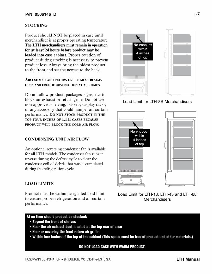
Load Limit for LTH-8S Merchandisers
Load Limit for LTH-18, LTH-45 and LTH-68Merchandisers
NO PRODUCT
within 4 inches
of top
NO PRODUCT
within 4 inches
of top
At no time should product be stocked:
• Beyond the front of shelves
• Near the air exhaust duct located at the top rear of case
• Near or covering the front return air grille
• Within four inches of the top of the cabinet (This space must be free of product and other materials.)
DO NOT LOAD CASE WITH WARM PRODUCT.
STOCKING
Product should NOT be placed in case untilmerchandiser is at proper operating temperature.The LTH merchandisers must remain in operationfor at least 24 hours before product may beloaded into case cabinet. Proper rotation ofproduct during stocking is necessary to preventproduct loss. Always bring the oldest productto the front and set the newest to the back.
AIR EXHAUST AND RETURN GRILLE MUST REMAIN
OPEN AND FREE OF OBSTRUCTION AT ALL TIMES.
Do not allow product, packages, signs, etc. toblock air exhaust or return grille. Do not usenon-approved shelving, baskets, display racks,or any accessory that could hamper air curtainperformance. DO NOT STOCK PRODUCT IN THE
TOP FOUR INCHES OF LTH CASES BECAUSE
PRODUCT WILL BLOCK THE COLD AIR FLOW.
CONDENSING UNIT AIR FLOW
An optional reversing condenser fan is availablefor all LTH models. The condenser fan runs inreverse during the defrost cycle to clear the condenser coil of debris that was accumulatedduring the refrigeration cycle.
LOAD LIMITS
Product must be within designated load limitto ensure proper refrigeration and air curtainperformance.
HUSSMANN CORPORATION • BRIDGETON, MO 63044-2483 U.S.A.
P/N 0506146_D
1-8 Installation
U.S. & Canada 1-800-922-1919 • Mexico 1-800-522-1900 • WWW.HUSSMANN.COM
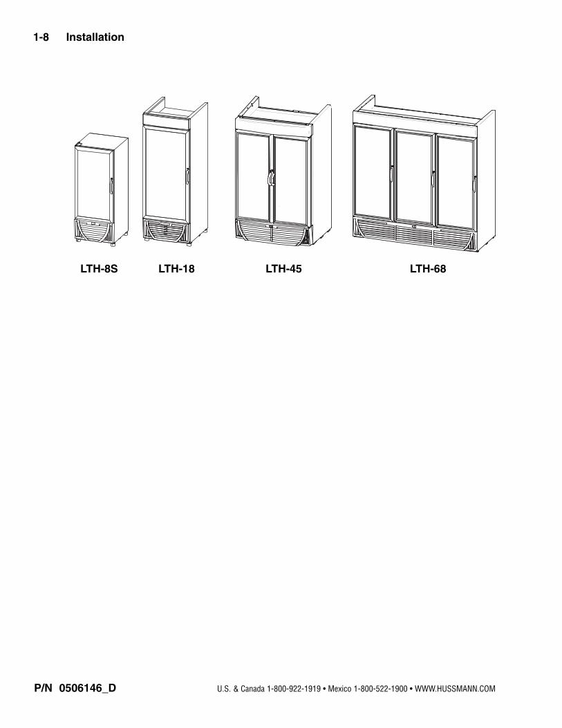
LTH-8S LTH-18 LTH-45 LTH-68
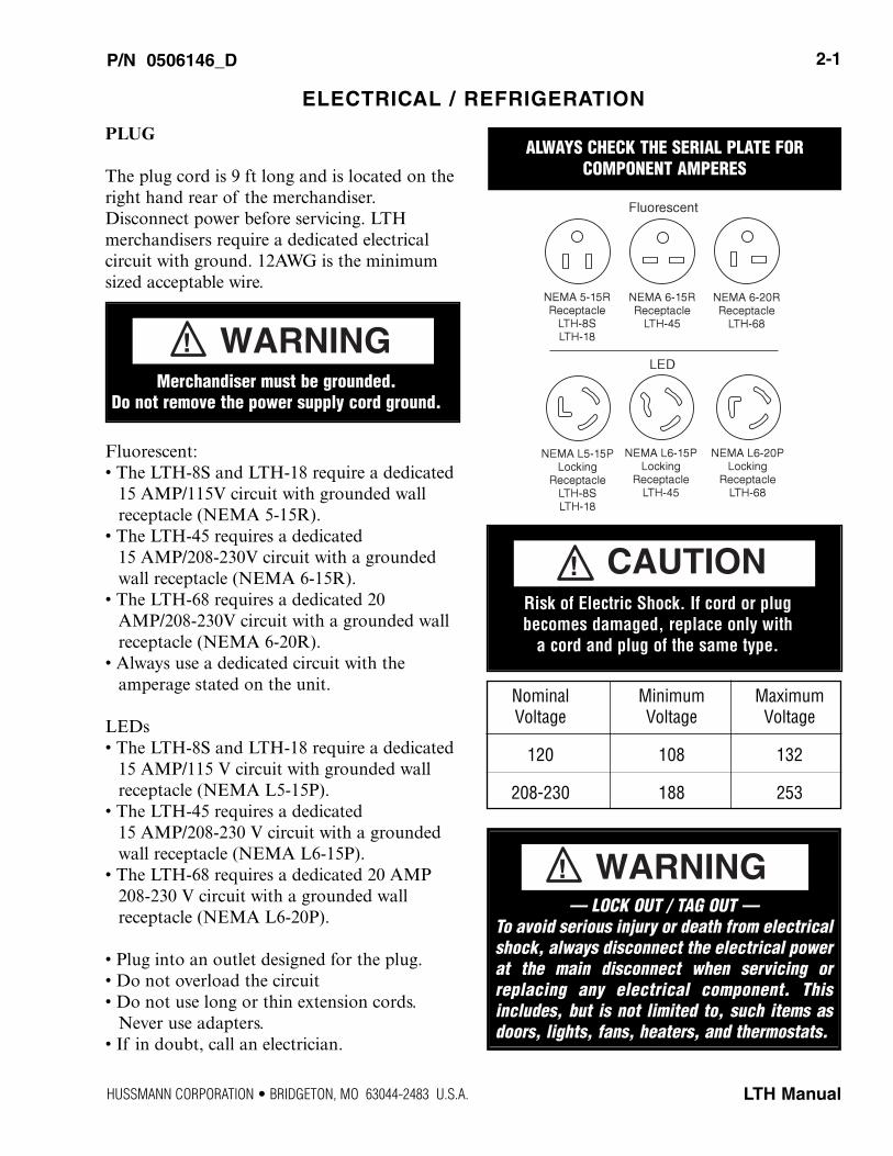
PLUG
The plug cord is 9 ft long and is located on theright hand rear of the merchandiser.Disconnect power before servicing. LTH merchandisers require a dedicated electrical circuit with ground. 12AWG is the minimumsized acceptable wire.
Fluorescent:• The LTH-8S and LTH-18 require a dedicated
15 AMP/115V circuit with grounded wallreceptacle (NEMA 5-15R).
• The LTH-45 requires a dedicated 15 AMP/208-230V circuit with a groundedwall receptacle (NEMA 6-15R).
• The LTH-68 requires a dedicated 20AMP/208-230V circuit with a grounded wallreceptacle (NEMA 6-20R).
• Always use a dedicated circuit with the amperage stated on the unit.
LEDs• The LTH-8S and LTH-18 require a dedicated
15 AMP/115 V circuit with grounded wallreceptacle (NEMA L5-15P).
• The LTH-45 requires a dedicated 15 AMP/208-230 V circuit with a groundedwall receptacle (NEMA L6-15P).
• The LTH-68 requires a dedicated 20 AMP208-230 V circuit with a grounded wall receptacle (NEMA L6-20P).
• Plug into an outlet designed for the plug.• Do not overload the circuit• Do not use long or thin extension cords.
Never use adapters.• If in doubt, call an electrician.
P/N 0506146_D 2-1
LTH Manual
ELECTRICAL / REFRIGERATION
Nominal Minimum MaximumVoltage Voltage Voltage
120 108 132
208-230 188 253
— LOCK OUT / TAG OUT —To avoid serious injury or death from electricalshock, always disconnect the electrical powerat the main disconnect when servicing orreplacing any electrical component. Thisincludes, but is not limited to, such items asdoors, lights, fans, heaters, and thermostats.
WARNING!
ALWAYS CHECK THE SERIAL PLATE FOR
COMPONENT AMPERES
Risk of Electric Shock. If cord or plug
becomes damaged, replace only with
a cord and plug of the same type.
CAUTION!
Merchandiser must be grounded.Do not remove the power supply cord ground.
WARNING!
HUSSMANN CORPORATION • BRIDGETON, MO 63044-2483 U.S.A.
REFRIGERATION
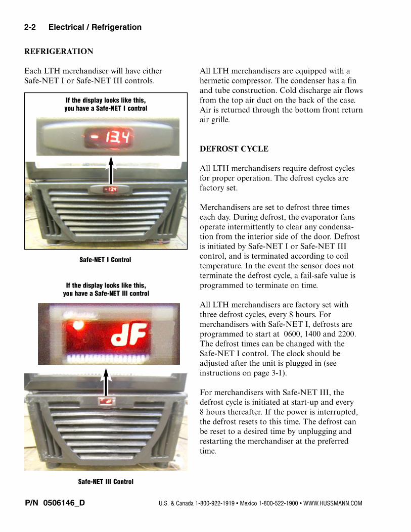
Each LTH merchandiser will have either Safe-NET I or Safe-NET III controls.
All LTH merchandisers are equipped with ahermetic compressor. The condenser has a finand tube construction. Cold discharge air flowsfrom the top air duct on the back of the case.Air is returned through the bottom front returnair grille.
DEFROST CYCLE
All LTH merchandisers require defrost cyclesfor proper operation. The defrost cycles arefactory set.
Merchandisers are set to defrost three timeseach day. During defrost, the evaporator fansoperate intermittently to clear any condensa-tion from the interior side of the door. Defrostis initiated by Safe-NET I or Safe-NET IIIcontrol, and is terminated according to coiltemperature. In the event the sensor does notterminate the defrost cycle, a fail-safe value isprogrammed to terminate on time.
All LTH merchandisers are factory set withthree defrost cycles, every 8 hours. For merchandisers with Safe-NET I, defrosts areprogrammed to start at 0600, 1400 and 2200.The defrost times can be changed with theSafe-NET I control. The clock should beadjusted after the unit is plugged in (seeinstructions on page 3-1).
For merchandisers with Safe-NET III, thedefrost cycle is initiated at start-up and every8 hours thereafter. If the power is interrupted,the defrost resets to this time. The defrost canbe reset to a desired time by unplugging andrestarting the merchandiser at the preferredtime.
P/N 0506146_D
2-2 Electrical / Refrigeration
U.S. & Canada 1-800-922-1919 • Mexico 1-800-522-1900 • WWW.HUSSMANN.COM
If the display looks like this,
you have a Safe-NET I control
Safe-NET I Control
Safe-NET III Control
If the display looks like this,
you have a Safe-NET III control
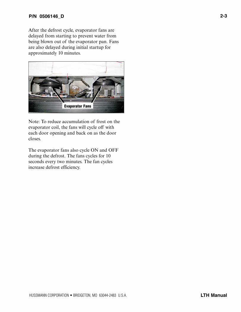
After the defrost cycle, evaporator fans aredelayed from starting to prevent water frombeing blown out of the evaporator pan. Fansare also delayed during initial startup forapproximately 10 minutes.
Note: To reduce accumulation of frost on theevaporator coil, the fans will cycle off witheach door opening and back on as the doorcloses.
The evaporator fans also cycle ON and OFFduring the defrost. The fans cycles for 10 seconds every two minutes. The fan cyclesincrease defrost efficiency.
P/N 0506146_D 2-3
LTH Manual
Evaporator Fans
HUSSMANN CORPORATION • BRIDGETON, MO 63044-2483 U.S.A.
NOTES:
P/N 0506146_D
2-4 Electrical / Refrigeration
U.S. & Canada 1-800-922-1919 • Mexico 1-800-522-1900 • WWW.HUSSMANN.COM
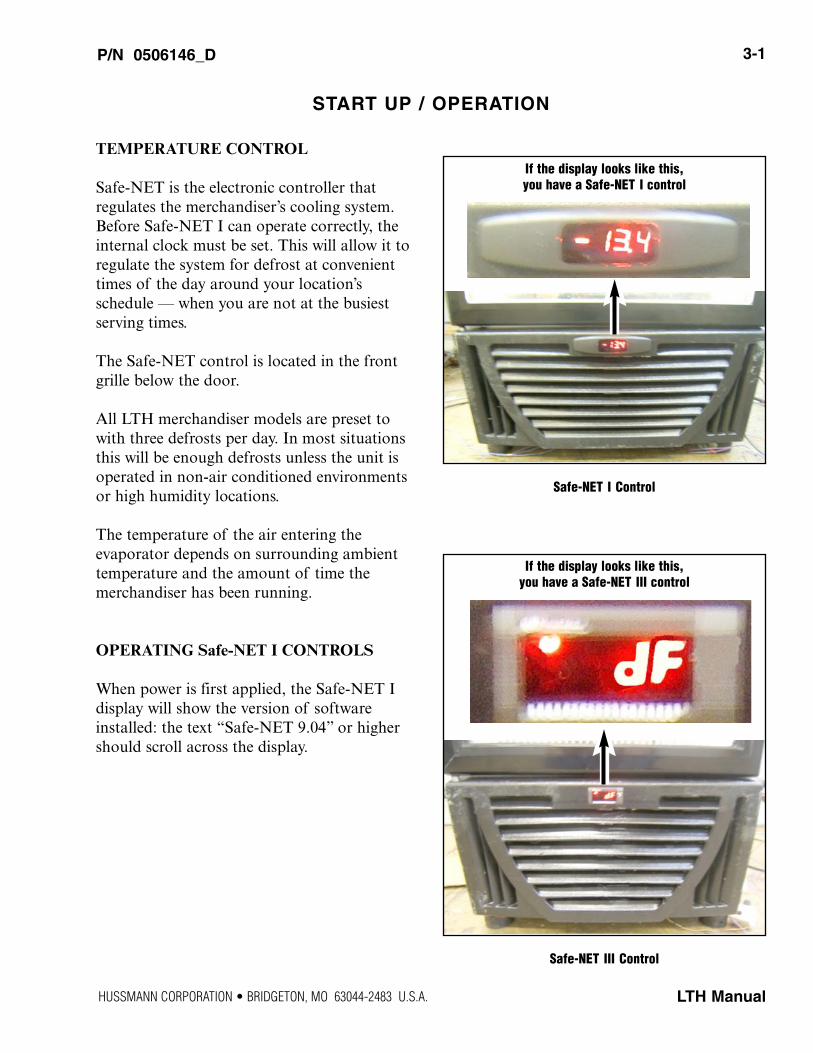
TEMPERATURE CONTROL
Safe-NET is the electronic controller that regulates the merchandiser’s cooling system.Before Safe-NET I can operate correctly, theinternal clock must be set. This will allow it toregulate the system for defrost at convenienttimes of the day around your location’s schedule — when you are not at the busiestserving times.
The Safe-NET control is located in the frontgrille below the door.
All LTH merchandiser models are preset towith three defrosts per day. In most situationsthis will be enough defrosts unless the unit isoperated in non-air conditioned environmentsor high humidity locations.
The temperature of the air entering the evaporator depends on surrounding ambienttemperature and the amount of time the merchandiser has been running.
OPERATING Safe-NET I CONTROLS
When power is first applied, the Safe-NET I display will show the version of softwareinstalled: the text “Safe-NET 9.04” or highershould scroll across the display.
P/N 0506146_D 3-1
LTH Manual
START UP / OPERATION
Safe-NET I Control
If the display looks like this,
you have a Safe-NET I control
Safe-NET III Control
If the display looks like this,
you have a Safe-NET III control
HUSSMANN CORPORATION • BRIDGETON, MO 63044-2483 U.S.A.
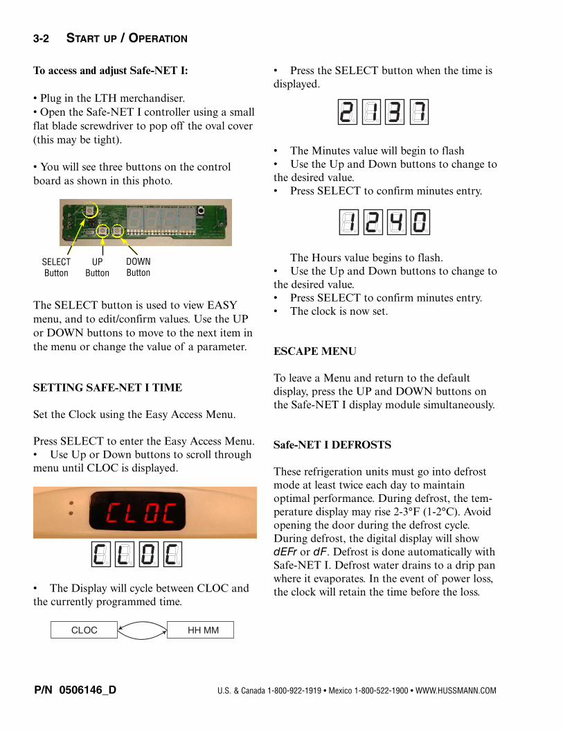
To access and adjust Safe-NET I:
• Plug in the LTH merchandiser.• Open the Safe-NET I controller using a smallflat blade screwdriver to pop off the oval cover(this may be tight).
• You will see three buttons on the controlboard as shown in this photo.
The SELECT button is used to view EASYmenu, and to edit/confirm values. Use the UPor DOWN buttons to move to the next item inthe menu or change the value of a parameter.
SETTING SAFE-NET I TIME
Set the Clock using the Easy Access Menu.
Press SELECT to enter the Easy Access Menu.• Use Up or Down buttons to scroll throughmenu until CLOC is displayed.
• The Display will cycle between CLOC andthe currently programmed time.
• Press the SELECT button when the time isdisplayed.
• The Minutes value will begin to flash• Use the Up and Down buttons to change tothe desired value.• Press SELECT to confirm minutes entry.
The Hours value begins to flash.• Use the Up and Down buttons to change tothe desired value.• Press SELECT to confirm minutes entry.• The clock is now set.
ESCAPE MENU
To leave a Menu and return to the default display, press the UP and DOWN buttons onthe Safe-NET I display module simultaneously.
Safe-NET I DEFROSTS
These refrigeration units must go into defrostmode at least twice each day to maintain optimal performance. During defrost, the tem-perature display may rise 2-3°F (1-2°C). Avoidopening the door during the defrost cycle.During defrost, the digital display will showdEFr or dF. Defrost is done automatically withSafe-NET I. Defrost water drains to a drip panwhere it evaporates. In the event of power loss,the clock will retain the time before the loss.
P/N 0506146_D
3-2 START UP / OPERATION
U.S. & Canada 1-800-922-1919 • Mexico 1-800-522-1900 • WWW.HUSSMANN.COM
SELECTButton
UPButton
DOWNButton
CLOC HH MM
LTH merchandisers are factory set with threedefrost cycles, eight hours apart. The first is setto 0600, the second to 1400 and the third is setto 2200. If these preset defrost times areacceptable to your business, no settings need tobe changed. Replace the Safe-NET I cover andgrille.
If the preset times need to be changed for yourbusiness schedule, or if additional defrosts areneeded because the merchandiser is in an envi-ronment out of the normal temperature range,the Safe-NET I controller can be set to meetthe requirements of your business.
LTH merchandisers have a door heater that iscontrolled by Safe-NET I. If condensationforms on the exterior of the door or doorframe, check that store ambient temperature isless than 80°F (27°C) and relative humidity isless than 55%. If condensation persists, calltech support.
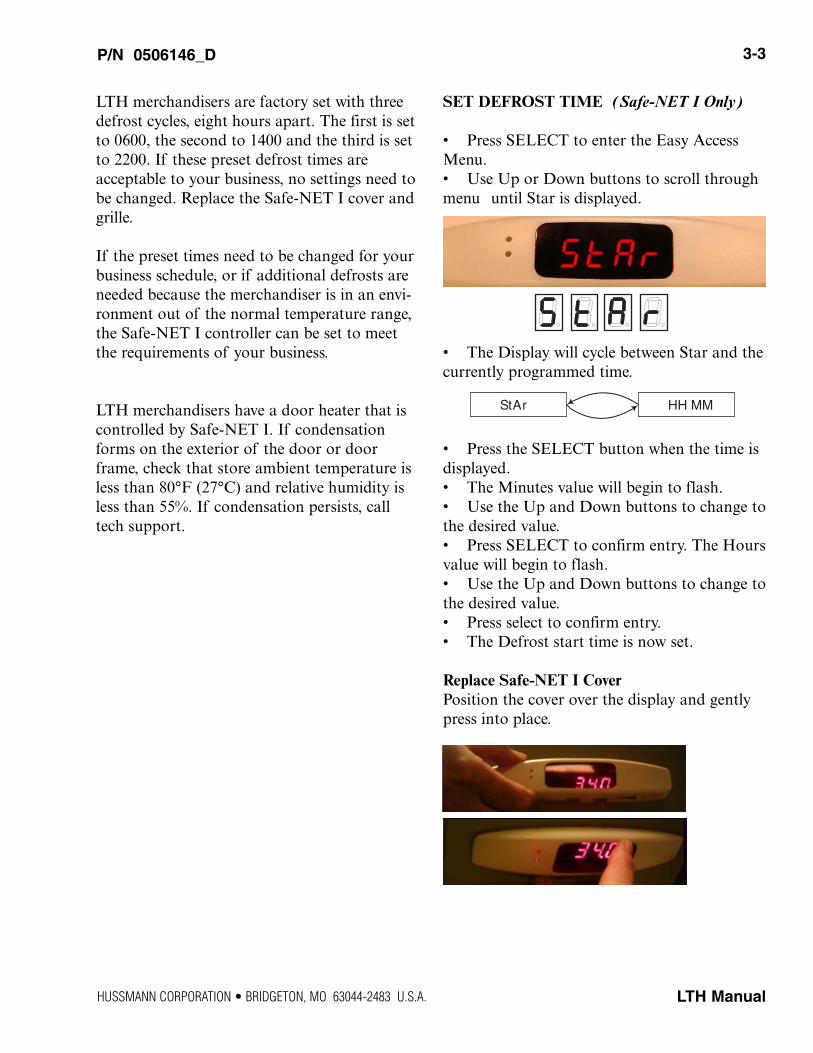
SET DEFROST TIME (Safe-NET I Only)
• Press SELECT to enter the Easy AccessMenu.• Use Up or Down buttons to scroll throughmenu until Star is displayed.
• The Display will cycle between Star and thecurrently programmed time.
• Press the SELECT button when the time isdisplayed.• The Minutes value will begin to flash. • Use the Up and Down buttons to change tothe desired value.• Press SELECT to confirm entry. The Hoursvalue will begin to flash. • Use the Up and Down buttons to change tothe desired value.• Press select to confirm entry.• The Defrost start time is now set.
Replace Safe-NET I CoverPosition the cover over the display and gentlypress into place.
P/N 0506146_D 3-3
LTH Manual
StAr HH MM
HUSSMANN CORPORATION • BRIDGETON, MO 63044-2483 U.S.A.
P/N 0506146_D
3-4 START UP / OPERATION
U.S. & Canada 1-800-922-1919 • Mexico 1-800-522-1900 • WWW.HUSSMANN.COM
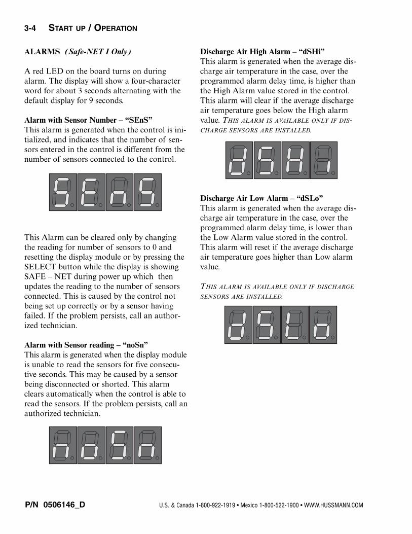
ALARMS (Safe-NET I Only)
A red LED on the board turns on duringalarm. The display will show a four-characterword for about 3 seconds alternating with thedefault display for 9 seconds.
Alarm with Sensor Number – “SEnS”This alarm is generated when the control is ini-tialized, and indicates that the number of sen-sors entered in the control is different from thenumber of sensors connected to the control.
This Alarm can be cleared only by changingthe reading for number of sensors to 0 andresetting the display module or by pressing theSELECT button while the display is showingSAFE – NET during power up which thenupdates the reading to the number of sensorsconnected. This is caused by the control notbeing set up correctly or by a sensor havingfailed. If the problem persists, call an author-ized technician.
Alarm with Sensor reading – “noSn”This alarm is generated when the display moduleis unable to read the sensors for five consecu-tive seconds. This may be caused by a sensorbeing disconnected or shorted. This alarmclears automatically when the control is able toread the sensors. If the problem persists, call anauthorized technician.
Discharge Air High Alarm – “dSHi”This alarm is generated when the average dis-charge air temperature in the case, over theprogrammed alarm delay time, is higher thanthe High Alarm value stored in the control.This alarm will clear if the average dischargeair temperature goes below the High alarmvalue. THIS ALARM IS AVAILABLE ONLY IF DIS-CHARGE SENSORS ARE INSTALLED.
Discharge Air Low Alarm – “dSLo”This alarm is generated when the average dis-charge air temperature in the case, over theprogrammed alarm delay time, is lower thanthe Low Alarm value stored in the control.This alarm will reset if the average dischargeair temperature goes higher than Low alarmvalue.
THIS ALARM IS AVAILABLE ONLY IF DISCHARGE
SENSORS ARE INSTALLED.
P/N 0506146_D 3-5
LTH ManualHUSSMANN CORPORATION • BRIDGETON, MO 63044-2483 U.S.A.
Compressor Off Cycle
Pull-down Compressor
On
Compressor Starts
10-Second Delay Until Compressor Starts
Defrost Cycle Will Terminate Once the Termination Temperature is Reached if Case is Cold (Turned Off and Back On)
Defrost Initiates at Start Up. Defrost Cycle is Temperature Terminated and Will Terminate Immediately When Warm
Start Up
Time to Subsequent Defrost (8 hrs or Demand Defrost)
Maximum Defrost Time 45-Minutes (Fail Safe)
Refrigeration Cycle
Off On
Time to Subsequent Defrost (8 Hrs or Demand Defrost)
Pull-down After Defrost
Compressor On
Defrost Cycle Terminates Once the Termination Temperature
Refrigeration Cycle
Maximum Defrost Time 45-Minutes (Fail Safe)
2 Min. Drip Time
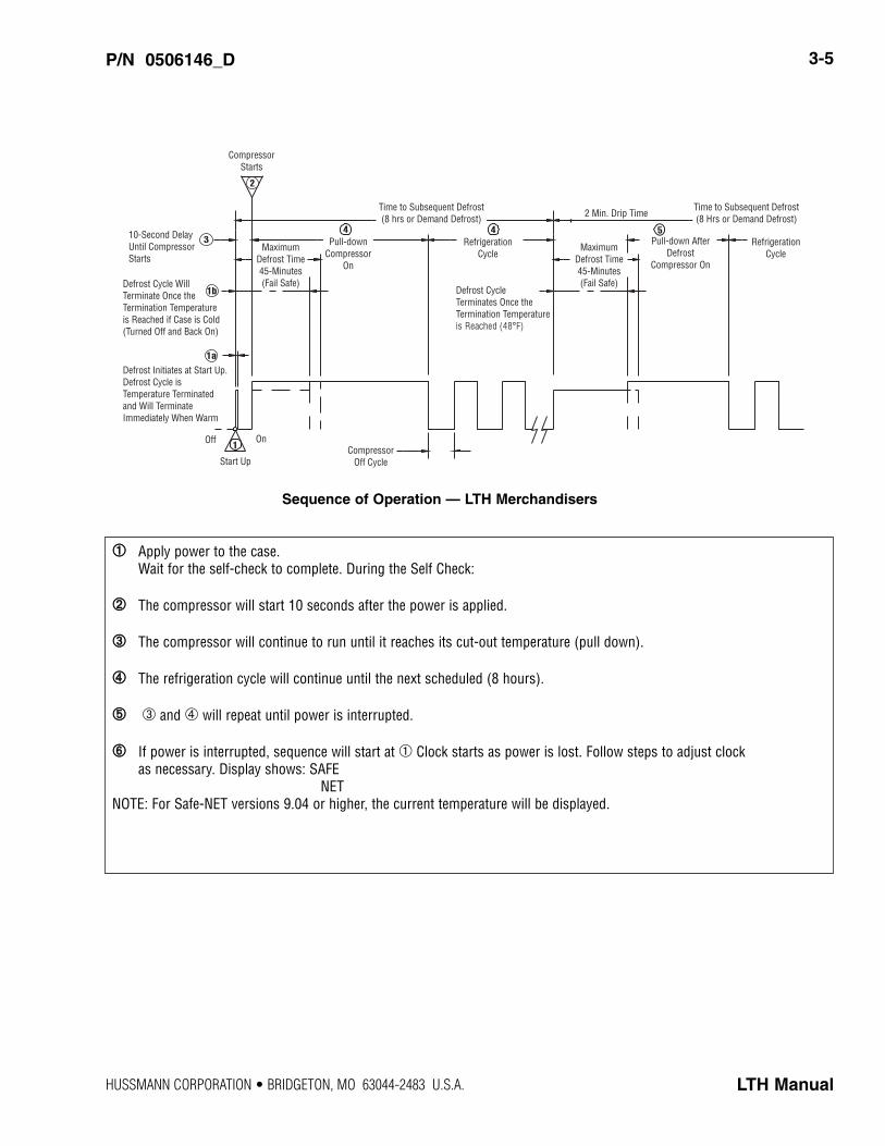
Sequence of Operation — LTH Merchandisers
➀➀ Apply power to the case.Wait for the self-check to complete. During the Self Check:
➁➁ The compressor will start 10 seconds after the power is applied.
➂➂ The compressor will continue to run until it reaches its cut-out temperature (pull down).
➃➃ The refrigeration cycle will continue until the next scheduled (8 hours).
➄➄ ➂ and ➃ will repeat until power is interrupted.
➅➅ If power is interrupted, sequence will start at ➀ Clock starts as power is lost. Follow steps to adjust clock as necessary. Display shows: SAFE
NETNOTE: For Safe-NET versions 9.04 or higher, the current temperature will be displayed.
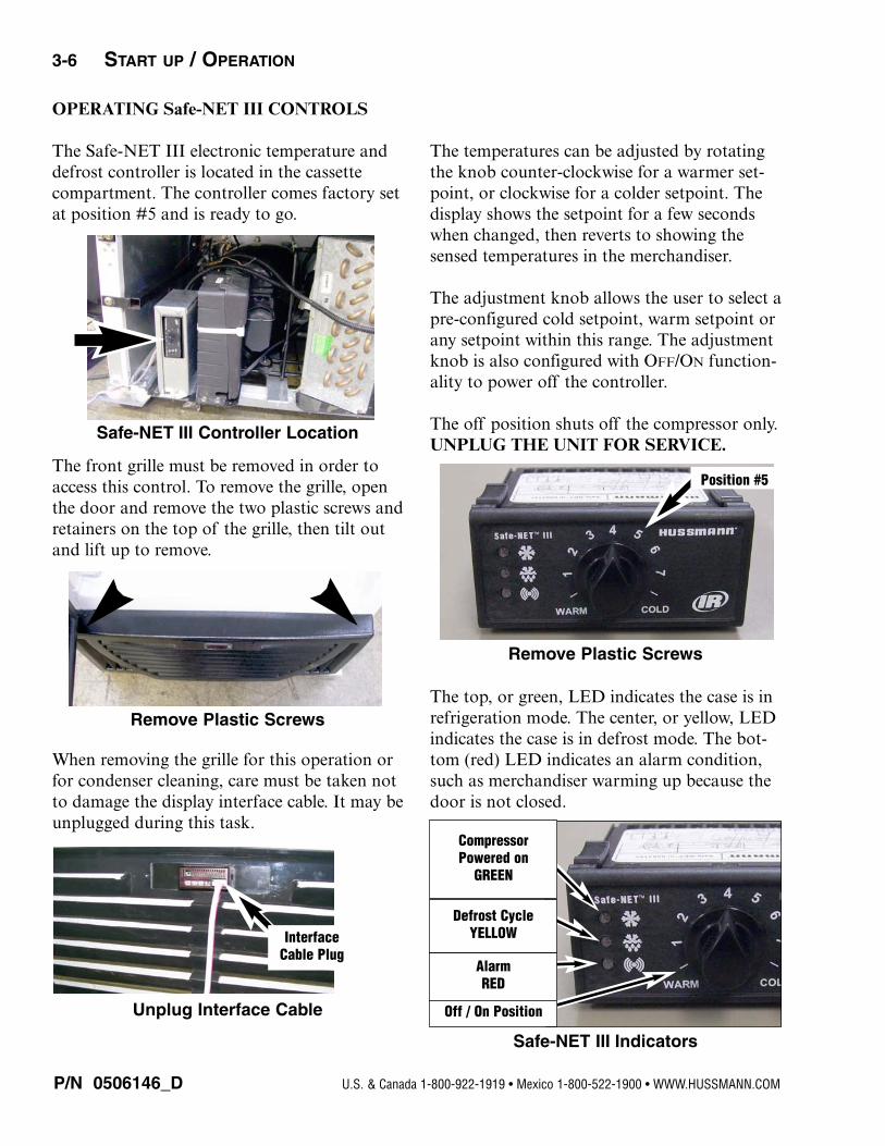
OPERATING Safe-NET III CONTROLS
The Safe-NET III electronic temperature anddefrost controller is located in the cassettecompartment. The controller comes factory setat position #5 and is ready to go.
The front grille must be removed in order toaccess this control. To remove the grille, openthe door and remove the two plastic screws andretainers on the top of the grille, then tilt outand lift up to remove.
When removing the grille for this operation orfor condenser cleaning, care must be taken notto damage the display interface cable. It may beunplugged during this task.
The temperatures can be adjusted by rotatingthe knob counter-clockwise for a warmer set-point, or clockwise for a colder setpoint. Thedisplay shows the setpoint for a few secondswhen changed, then reverts to showing thesensed temperatures in the merchandiser.
The adjustment knob allows the user to select apre-configured cold setpoint, warm setpoint orany setpoint within this range. The adjustmentknob is also configured with OFF/ON function-ality to power off the controller.
The off position shuts off the compressor only.UNPLUG THE UNIT FOR SERVICE.
The top, or green, LED indicates the case is inrefrigeration mode. The center, or yellow, LEDindicates the case is in defrost mode. The bot-tom (red) LED indicates an alarm condition,such as merchandiser warming up because thedoor is not closed.
P/N 0506146_D
3-6 START UP / OPERATION
U.S. & Canada 1-800-922-1919 • Mexico 1-800-522-1900 • WWW.HUSSMANN.COM
Safe-NET III Controller Location
Remove Plastic Screws
Unplug Interface Cable
Interface
Cable Plug
Remove Plastic Screws
Position #5
Safe-NET III Indicators
Compressor
Powered on
GREEN
Defrost Cycle
YELLOW
Alarm
RED
Off / On Position
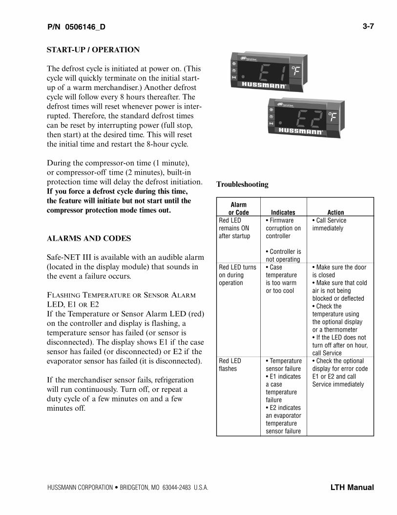
START-UP / OPERATION
The defrost cycle is initiated at power on. (Thiscycle will quickly terminate on the initial start-up of a warm merchandiser.) Another defrostcycle will follow every 8 hours thereafter. Thedefrost times will reset whenever power is inter-rupted. Therefore, the standard defrost timescan be reset by interrupting power (full stop,then start) at the desired time. This will reset the initial time and restart the 8-hour cycle.
During the compressor-on time (1 minute), or compressor-off time (2 minutes), built-in protection time will delay the defrost initiation.If you force a defrost cycle during this time, the feature will initiate but not start until thecompressor protection mode times out.
ALARMS AND CODES
Safe-NET III is available with an audible alarm(located in the display module) that sounds inthe event a failure occurs.
FLASHING TEMPERATURE OR SENSOR ALARM
LED, E1 OR E2If the Temperature or Sensor Alarm LED (red)on the controller and display is flashing, a temperature sensor has failed (or sensor is disconnected). The display shows E1 if the casesensor has failed (or disconnected) or E2 if theevaporator sensor has failed (it is disconnected).
If the merchandiser sensor fails, refrigerationwill run continuously. Turn off, or repeat aduty cycle of a few minutes on and a few minutes off.
Troubleshooting
P/N 0506146_D 3-7
LTH ManualHUSSMANN CORPORATION • BRIDGETON, MO 63044-2483 U.S.A.
Alarm
or Code Indicates Action
Red LED • Firmware • Call Serviceremains ON corruption on immediatelyafter startup controller
• Controller is not operating
Red LED turns • Case • Make sure the door on during temperature is closedoperation is too warm • Make sure that cold
or too cool air is not being blocked or deflected• Check the temperature using the optional display or a thermometer• If the LED does not turn off after on hour,call Service
Red LED • Temperature • Check the optional flashes sensor failure display for error code
• E1 indicates E1 or E2 and call a case Service immediatelytemperature failure• E2 indicatesan evaporator temperature sensor failure
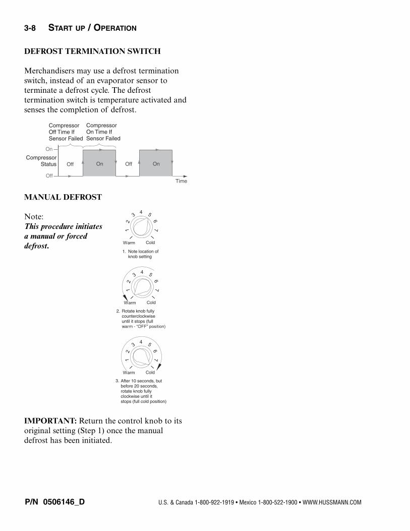
DEFROST TERMINATION SWITCH
Merchandisers may use a defrost terminationswitch, instead of an evaporator sensor to terminate a defrost cycle. The defrost termination switch is temperature activated andsenses the completion of defrost.
MANUAL DEFROST
Note: This procedure initiatesa manual or forceddefrost.
IMPORTANT: Return the control knob to itsoriginal setting (Step 1) once the manualdefrost has been initiated.
P/N 0506146_D
3-8 START UP / OPERATION
U.S. & Canada 1-800-922-1919 • Mexico 1-800-522-1900 • WWW.HUSSMANN.COM
On
OffTime
Off On Off On
Compressor Off Time If Sensor Failed
Compressor On Time If Sensor Failed
Compressor Status
12
34 5
67
I I
Warm Cold
Rotate knob fully counterclockwise until it stops (full
2.
12
34 5
67
I I
Warm Cold
Note location of knob setting
1.
12
34 5
67
I I
Warm Cold
3. After 10 seconds, but before 20 seconds, rotate knob fully clockwise until it stops (full cold position)
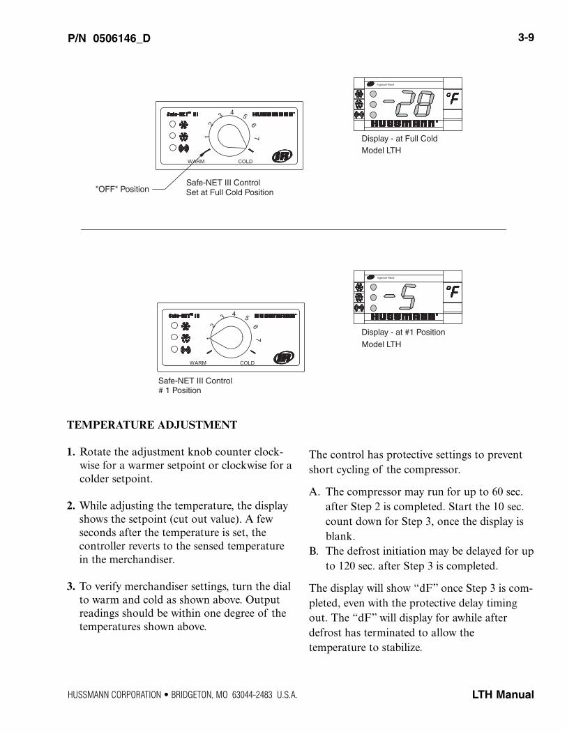
TEMPERATURE ADJUSTMENT
1. Rotate the adjustment knob counter clock-wise for a warmer setpoint or clockwise for acolder setpoint.
2. While adjusting the temperature, the displayshows the setpoint (cut out value). A few seconds after the temperature is set, the controller reverts to the sensed temperaturein the merchandiser.
3. To verify merchandiser settings, turn the dialto warm and cold as shown above. Outputreadings should be within one degree of thetemperatures shown above.
The control has protective settings to preventshort cycling of the compressor.
A. The compressor may run for up to 60 sec.after Step 2 is completed. Start the 10 sec.count down for Step 3, once the display isblank.
B. The defrost initiation may be delayed for upto 120 sec. after Step 3 is completed.
The display will show “dF” once Step 3 is com-pleted, even with the protective delay timingout. The “dF” will display for awhile afterdefrost has terminated to allow the temperature to stabilize.
P/N 0506146_D 3-9
LTH ManualHUSSMANN CORPORATION • BRIDGETON, MO 63044-2483 U.S.A.
76
COLDWARM
12
43 5
Display - at Full Cold Model LTH
Display - at #1 Position
Model LTH
76
COLDWARM
12
43 5
"OFF" PositionSafe-NET III ControlSet at Full Cold Position
Safe-NET III Control # 1 Position
Ingersoll Rand
Ingersoll Rand

P/N 0506146_D
3-10 START UP / OPERATION
U.S. & Canada 1-800-922-1919 • Mexico 1-800-522-1900 • WWW.HUSSMANN.COM
A
89
1011
Typical Sensor to Control Configuration
Control Sensor (Black Sheath)
Evaporator Sensor (Defrost Term.) inserted into the Evaporator Fins or into the Suction Line
(Yellow Sheath)
Yellow Sheath (Evaporator Sensor Defrost Termination)
Black Sheath (Air Sensor-Display)
Yellow
Black
Black (Air)
Black (Evap.)
White (Common for Both Sensors)
Black (Air Sensor #8)
Black (Evaporator Sensor #9)
#11 Not Used
White (Common Both Sensors #10)
Detail A
Yellow Sensor: Defrost Termination (Evaporator) Black Sensor: Control (Air)
— LOCK OUT / TAG OUT —To avoid serious injury or death from electricalshock, always disconnect the electrical powerat the main disconnect when servicing orreplacing any electrical component. Thisincludes, but is not limited to, such items asdoors, lights, fans, heaters, and thermostats.
WARNING!
P/N 0506146_D 3-11
LTH ManualHUSSMANN CORPORATION • BRIDGETON, MO 63044-2483 U.S.A.
Compressor Off Cycle
Pull-down Compressor
On
Compressor Starts
10-Second Delay Until Compressor Starts
Defrost Cycle Will Terminate Once the Termination Temperature is Reached if Case is Cold (Turned Off and Back On)
Defrost Initiates at Start Up. Defrost Cycle is Temperature Terminated and Will Terminate Immediately When Warm
Start Up
Time to Subsequent Defrost (8 hrs or Demand Defrost)
Maximum Defrost Time 45-Minutes (Fail Safe)
Refrigeration Cycle
Off On
Time to Subsequent Defrost (8 Hrs or Demand Defrost)
Pull-down After Defrost
Compressor On
Defrost Cycle Terminates Once the Termination Temperature
Refrigeration Cycle
Maximum Defrost Time 45-Minutes (Fail Safe)
2 Min. Drip Time
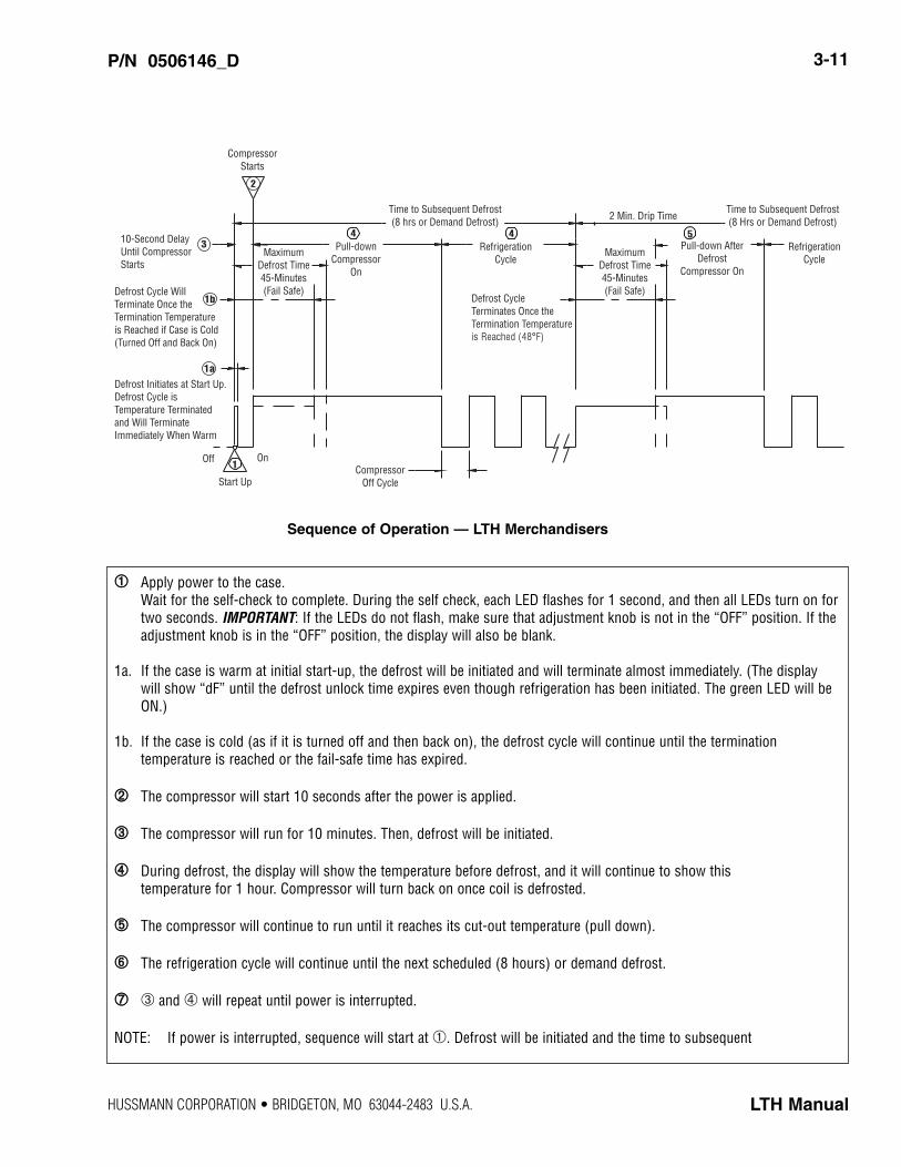
Sequence of Operation — LTH Merchandisers
➀➀ Apply power to the case.Wait for the self-check to complete. During the self check, each LED flashes for 1 second, and then all LEDs turn on fortwo seconds. IMPORTANT: If the LEDs do not flash, make sure that adjustment knob is not in the “OFF” position. If theadjustment knob is in the “OFF” position, the display will also be blank.
1a. If the case is warm at initial start-up, the defrost will be initiated and will terminate almost immediately. (The displaywill show “dF” until the defrost unlock time expires even though refrigeration has been initiated. The green LED will beON.)
1b. If the case is cold (as if it is turned off and then back on), the defrost cycle will continue until the termination temperature is reached or the fail-safe time has expired.
➁➁ The compressor will start 10 seconds after the power is applied.
➂➂ The compressor will run for 10 minutes. Then, defrost will be initiated.
➃➃ During defrost, the display will show the temperature before defrost, and it will continue to show this temperature for 1 hour. Compressor will turn back on once coil is defrosted.
➄➄ The compressor will continue to run until it reaches its cut-out temperature (pull down).
➅➅ The refrigeration cycle will continue until the next scheduled (8 hours) or demand defrost.
➆➆ ➂ and ➃ will repeat until power is interrupted.
NOTE: If power is interrupted, sequence will start at ➀. Defrost will be initiated and the time to subsequent
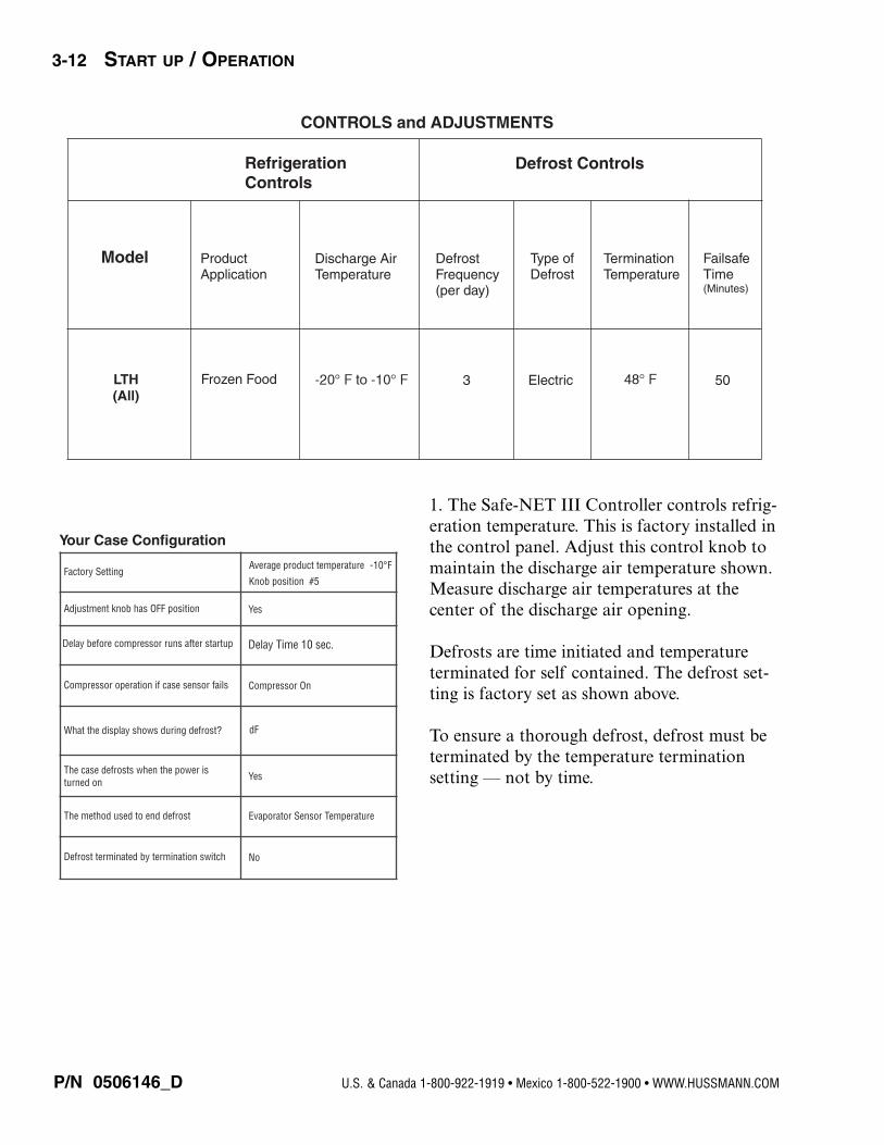
1. The Safe-NET III Controller controls refrig-eration temperature. This is factory installed inthe control panel. Adjust this control knob tomaintain the discharge air temperature shown.Measure discharge air temperatures at the center of the discharge air opening.
Defrosts are time initiated and temperature terminated for self contained. The defrost set-ting is factory set as shown above.
To ensure a thorough defrost, defrost must beterminated by the temperature termination setting — not by time.
P/N 0506146_D
3-12 START UP / OPERATION
U.S. & Canada 1-800-922-1919 • Mexico 1-800-522-1900 • WWW.HUSSMANN.COM
CONTROLS and ADJUSTMENTS
Model Product Application
Discharge Air Temperature
Defrost Frequency (per day)
Type of Defrost
Termination Temperature
Failsafe Time (Minutes)
3 Electric 50
Refrigeration Controls
Defrost Controls
LTH (All)
Frozen Food
Your Case Configuration
Factory SettingAverage product temperature
Knob position #5
Adjustment knob has OFF position Yes
Delay Time 10 sec.Delay before compressor runs after startup
Compressor operation if case sensor fails
What the display shows during defrost?
YesThe case defrosts when the power is turned on
The method used to end defrost Evaporator Sensor Temperature
Defrost terminated by termination switch
-10 F
No
Compressor On
dF
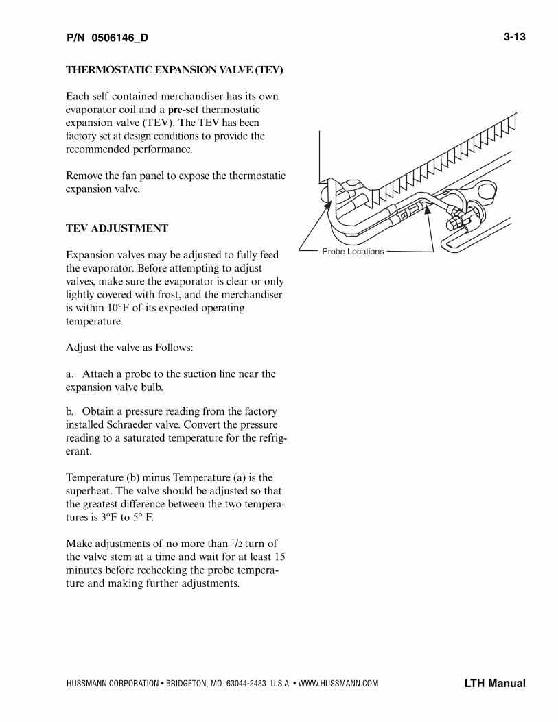
THERMOSTATIC EXPANSION VALVE (TEV)
Each self contained merchandiser has its ownevaporator coil and a pre-set thermostaticexpansion valve (TEV). The TEV has been factory set at design conditions to provide the recommended performance.
Remove the fan panel to expose the thermostaticexpansion valve.
TEV ADJUSTMENT
Expansion valves may be adjusted to fully feedthe evaporator. Before attempting to adjustvalves, make sure the evaporator is clear or onlylightly covered with frost, and the merchandiseris within 10°F of its expected operating temperature.
Adjust the valve as Follows:
a. Attach a probe to the suction line near theexpansion valve bulb.
b. Obtain a pressure reading from the factoryinstalled Schraeder valve. Convert the pressurereading to a saturated temperature for the refrig-erant.
Temperature (b) minus Temperature (a) is thesuperheat. The valve should be adjusted so thatthe greatest difference between the two tempera-tures is 3°F to 5° F.
Make adjustments of no more than 1/2 turn ofthe valve stem at a time and wait for at least 15minutes before rechecking the probe tempera-ture and making further adjustments.
P/N 0506146_D 3-13
LTH ManualHUSSMANN CORPORATION • BRIDGETON, MO 63044-2483 U.S.A. • WWW.HUSSMANN.COM
Probe Locations

NOTES:
P/N 0506146_D
3-14 START UP / OPERATION
U.S. & Canada 1-800-922-1919 • Mexico 1-800-522-1900 • WWW.HUSSMANN.COM
CARE AND CLEANING
Long life and satisfactory performance of anyequipment is dependent upon the care itreceives. To ensure long life, proper sanitationand minimum maintenance costs, this unitshould be thoroughly cleaned, all debrisremoved and the interiors washed down.Cleaning often will control or eliminate odorbuildup. Frequency of cleaning is dependenton usage and local health requirements.
Exterior Surfaces
The exterior surfaces must be cleaned with amild detergent and warm water to protect andmaintain their attractive finish.
NEVER USE ABRASIVE CLEANERS OR SCOURING
PADS. NEVER USE CAUSTIC SODA, KEROSENE,GASOLINE, THINNER, SOLVENTS, DETERGENTS,ACIDS, CHEMICALS OR ABRASIVES. DO NOT USE
AMMONIA-BASED CLEANERS ON ACRYLIC PARTS.
Interior Surfaces
DO NOT USE AMMONIA-BASED PRODUCTS TO
CLEAN LIGHT SHIELDS. NEVER USE ABRASIVE
CLEANSERS OR SCOURING PADS.
The interior surfaces may be cleaned with mostdomestic detergents and sanitizing solutionswith no harm to the surface. Always read andfollow the manufacturer's instructions whenusing any cleaning product.
Do NOT Use:• Abrasive cleansers and scouring pads, as
these will mar the finish.• Coarse paper towels on coated glass.• Ammonia-based cleaners on acrylic parts.• A hose on lighted shelves or submerge the
shelves in water.• Solvent, oil or acidic based cleaners on any
interior surfaces.• A hose on rail lights, canopy lights or any
other electrical connection.
Do:• First turn off refrigeration, then disconnect
electrical power.• Remove product and loose debris.• Thoroughly clean all surfaces with soap and
hot water. DO NOT USE STEAM OR HIGH WATER
PRESSURE HOSES TO WASH THE INTERIOR.THESE DESTROY MERCHANDISER’S SEALING
CAUSING LEAKS AND POOR PERFORMANCE.• Take care to minimize direct contact between
fan motors and cleaning or rinse water.• Rinse with hot water, but do NOT flood. • Allow merchandiser to dry before resuming
operation.• Wipe down lighted shelves with a damp
sponge or cloth so that water does not enterthe light channel. DO NOT USE A HOSE OR
SUBMERGE SHELVES IN WATER.• After cleaning is completed, restore power
and turn on the merchandiser.
P/N 0506146_D 4-1
LTH Manual
MAINTENANCE
Do not use HOT water on COLD glass surfaces.This can cause the glass to shatter and couldresult in personal injury. Allow glass fronts,ends and service doors to warm before applyinghot water.
WARNING!
To reduce the risk of fire, electrical shock orinjury when cleaning this merchandiser:
• Unplug the merchandiser before cleaning;• Keep all liquids away from electrical and
electronic components;• Do not use any mechanical device or other
means to speed the defrost process, exceptas recommended by the manufacturer.
WARNING!
HUSSMANN CORPORATION • BRIDGETON, MO 63044-2483 U.S.A.
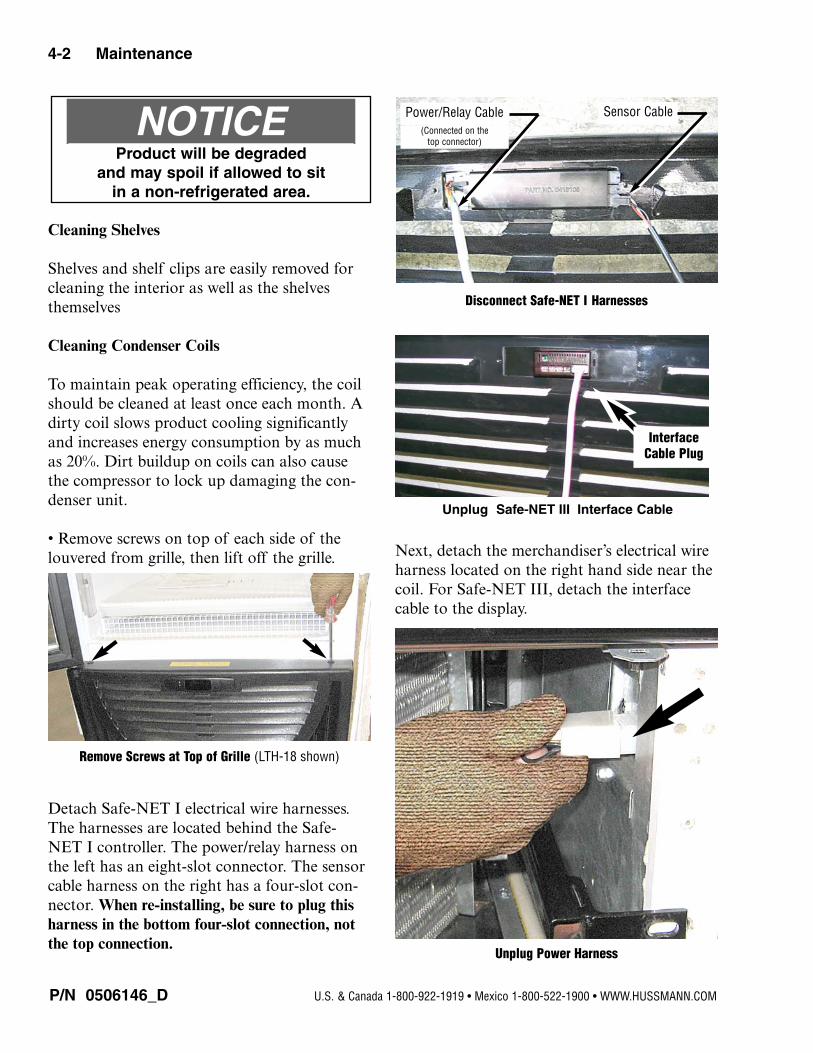
Cleaning Shelves
Shelves and shelf clips are easily removed forcleaning the interior as well as the shelvesthemselves
Cleaning Condenser Coils
To maintain peak operating efficiency, the coilshould be cleaned at least once each month. Adirty coil slows product cooling significantlyand increases energy consumption by as muchas 20%. Dirt buildup on coils can also causethe compressor to lock up damaging the con-denser unit.
• Remove screws on top of each side of thelouvered from grille, then lift off the grille.
Detach Safe-NET I electrical wire harnesses.The harnesses are located behind the Safe-NET I controller. The power/relay harness onthe left has an eight-slot connector. The sensorcable harness on the right has a four-slot con-nector. When re-installing, be sure to plug thisharness in the bottom four-slot connection, notthe top connection.
Next, detach the merchandiser’s electrical wireharness located on the right hand side near thecoil. For Safe-NET III, detach the interfacecable to the display.
P/N 0506146_D
4-2 Maintenance
U.S. & Canada 1-800-922-1919 • Mexico 1-800-522-1900 • WWW.HUSSMANN.COM
Remove Screws at Top of Grille (LTH-18 shown)
Disconnect Safe-NET I Harnesses
Unplug Power Harness
Product will be degraded and may spoil if allowed to sit
in a non-refrigerated area.
NOTICE Power/Relay Cable Sensor Cable
Unplug Safe-NET III Interface Cable
Interface
Cable Plug
(Connected on the top connector)
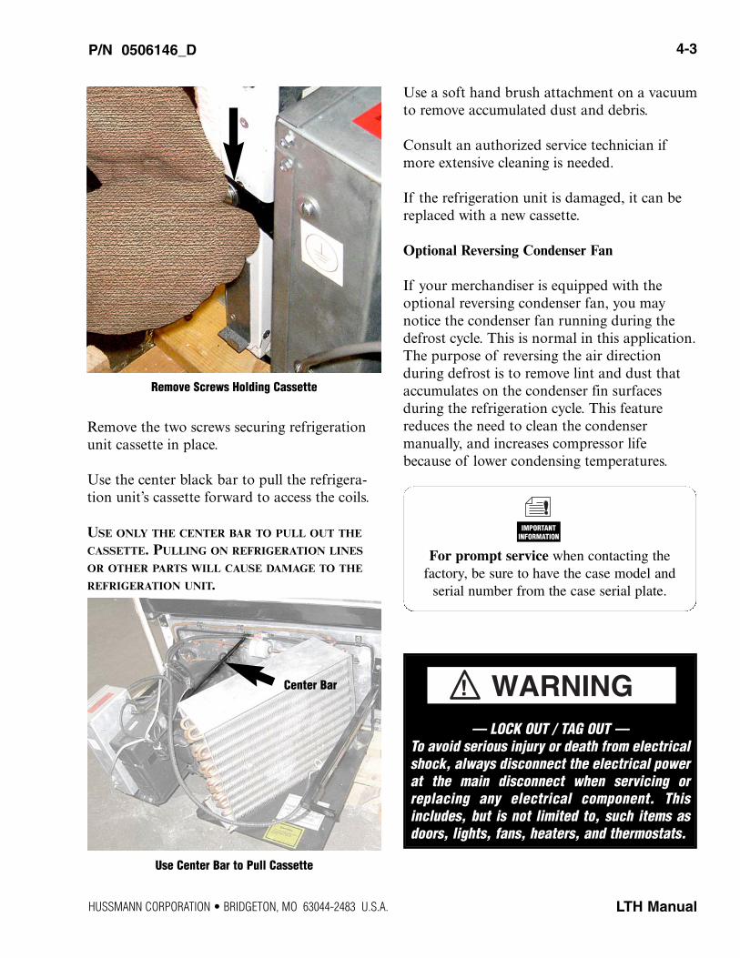
Remove the two screws securing refrigerationunit cassette in place.
Use the center black bar to pull the refrigera-tion unit’s cassette forward to access the coils.
USE ONLY THE CENTER BAR TO PULL OUT THE
CASSETTE. PULLING ON REFRIGERATION LINES
OR OTHER PARTS WILL CAUSE DAMAGE TO THE
REFRIGERATION UNIT.
Use a soft hand brush attachment on a vacuumto remove accumulated dust and debris.
Consult an authorized service technician ifmore extensive cleaning is needed.
If the refrigeration unit is damaged, it can bereplaced with a new cassette.
Optional Reversing Condenser Fan
If your merchandiser is equipped with theoptional reversing condenser fan, you maynotice the condenser fan running during thedefrost cycle. This is normal in this application.The purpose of reversing the air direction during defrost is to remove lint and dust thataccumulates on the condenser fin surfaces during the refrigeration cycle. This featurereduces the need to clean the condenser manually, and increases compressor lifebecause of lower condensing temperatures.
P/N 0506146_D 4-3
LTH Manual
For prompt service when contacting the factory, be sure to have the case model and
serial number from the case serial plate.
IMPORTANTINFORMATION
Use Center Bar to Pull Cassette
Remove Screws Holding Cassette
Center Bar
HUSSMANN CORPORATION • BRIDGETON, MO 63044-2483 U.S.A.
— LOCK OUT / TAG OUT —To avoid serious injury or death from electricalshock, always disconnect the electrical powerat the main disconnect when servicing orreplacing any electrical component. Thisincludes, but is not limited to, such items asdoors, lights, fans, heaters, and thermostats.
WARNING!

Cleaning the Wash Out Drain
The wash out drain is located behind the refrig-eration cassette and can be cleaned with waterand wiped with a soft cloth. Ensure drain isunobstructed before replacing cassette.
The washout drain flows into an auxiliarywaste line.
Next remove the auxiliary waste line cap todrain any excess water. Place a dry towel overthe line to absorb water.
Replace cap, cables and cassette.
TIPS AND TROUBLESHOOTING
There are a few simple things to check beforecalling for service:
1. Product not cold? Refrigeration unit requires24 hours at initial startup to cool down tooperating temperature with NO PRODUCT
LOADED in merchandiser. Ask when merchandiser was stocked, and what theusage has been. It may take 30 minutes ormore for product to chill following stocking.
2. Check the door and door seal for air leaks.
3. Power Supply:Is the unit plugged in? Is there power to the unit?
4. LocationWhat are the ambient conditions—temperature and humidity, direct sun, nearbysource of heat, such as oven or grill? Is theunit level?Has the unit been moved recently?
5. Shelves and StockingAre the standard shelves in the correctplaces?Is the product stocked properly?Is the bottom shelf at the proper location?
6. Confirm that the defrost schedule is properly set using Safe-NET I.Check for Safe-NET error messages.
P/N 0506146_D
4-4 Maintenance
U.S. & Canada 1-800-922-1919 • Mexico 1-800-522-1900 • WWW.HUSSMANN.COM
Auxiliary Waste Line
Replace Cap, Cables and Cassette
For prompt service when contacting the factory, be sure to have the case model and
serial number from the case serial plate.
IMPORTANTINFORMATION
Cap
Cable
Wash Out Drain
Drain
REPLACING FLUORESCENT LAMPS
Fluorescent lamps have a plastic shield. Whenthe lamp is replaced, keep the lamp shield toinstall over the new lamp..
The switch under the display lamp cover oper-ates both the display lamp and interior lamps.
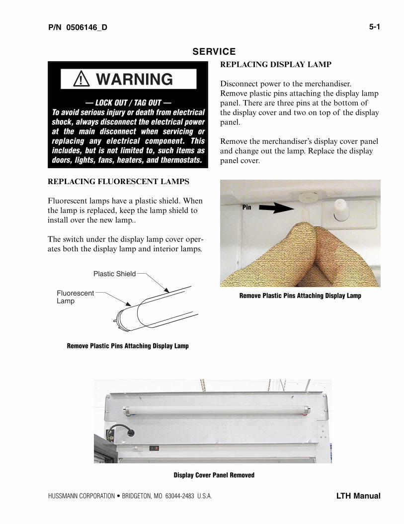
REPLACING DISPLAY LAMP
Disconnect power to the merchandiser.Remove plastic pins attaching the display lamppanel. There are three pins at the bottom ofthe display cover and two on top of the displaypanel.
Remove the merchandiser’s display cover paneland change out the lamp. Replace the displaypanel cover.
P/N 0506146_D 5-1
LTH Manual
SERVICE
Remove Plastic Pins Attaching Display Lamp
Plastic Shield
Fluorescent Lamp
Remove Plastic Pins Attaching Display Lamp
Display Cover Panel Removed
Pin
HUSSMANN CORPORATION • BRIDGETON, MO 63044-2483 U.S.A.
— LOCK OUT / TAG OUT —To avoid serious injury or death from electricalshock, always disconnect the electrical powerat the main disconnect when servicing orreplacing any electrical component. Thisincludes, but is not limited to, such items asdoors, lights, fans, heaters, and thermostats.
WARNING!
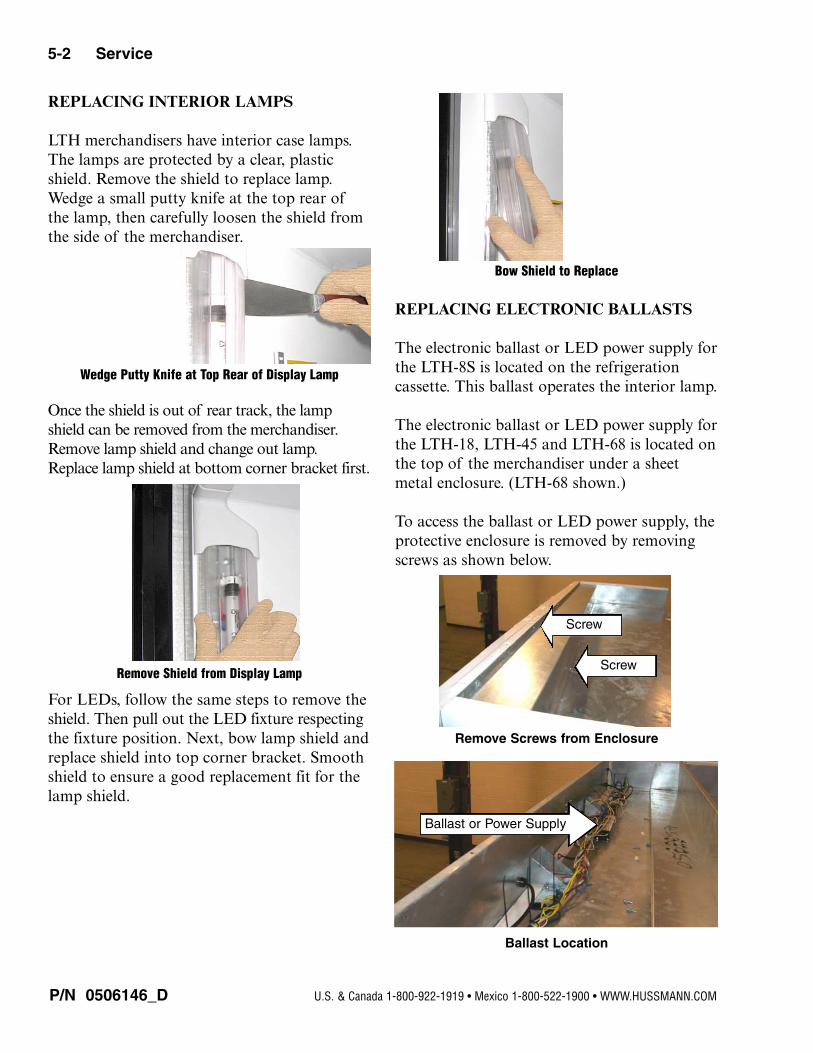
REPLACING INTERIOR LAMPS
LTH merchandisers have interior case lamps.The lamps are protected by a clear, plasticshield. Remove the shield to replace lamp.Wedge a small putty knife at the top rear ofthe lamp, then carefully loosen the shield fromthe side of the merchandiser.
Once the shield is out of rear track, the lampshield can be removed from the merchandiser.Remove lamp shield and change out lamp.Replace lamp shield at bottom corner bracket first.
For LEDs, follow the same steps to remove theshield. Then pull out the LED fixture respectingthe fixture position. Next, bow lamp shield andreplace shield into top corner bracket. Smoothshield to ensure a good replacement fit for thelamp shield.
REPLACING ELECTRONIC BALLASTS
The electronic ballast or LED power supply forthe LTH-8S is located on the refrigeration cassette. This ballast operates the interior lamp.
The electronic ballast or LED power supply forthe LTH-18, LTH-45 and LTH-68 is located onthe top of the merchandiser under a sheetmetal enclosure. (LTH-68 shown.)
To access the ballast or LED power supply, theprotective enclosure is removed by removingscrews as shown below.
P/N 0506146_D
5-2 Service
U.S. & Canada 1-800-922-1919 • Mexico 1-800-522-1900 • WWW.HUSSMANN.COM
Wedge Putty Knife at Top Rear of Display Lamp
Bow Shield to Replace
Remove Shield from Display Lamp
Remove Screws from Enclosure
Ballast Location
Screw
Screw
Ballast or Power Supply
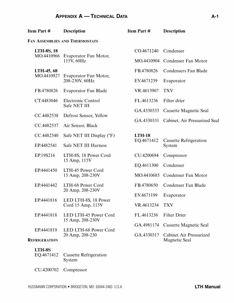
Item Part # Description
FAN ASSEMBLIES AND THERMOSTATS
LTH-8S, 18MO.4410966 Evaporator Fan Motor,
115V, 60Hz
LTH-45, 68MO.4410927 Evaporator Fan Motor,
208-230V, 60Hz
FB.4780826 Evaporator Fan Blade
CT.4483046 Electronic Control Safe NET III
CC.4482538 Defrost Sensor, Yellow
CC.4482537 Air Sensor, Black
CC.4482540 Safe NET III Display (ºF)
EP.4482541 Safe NET III Harness
EP.19S216 LTH-8S, 18 Power Cord 15 Amp, 115V
EP.4441450 LTH-45 Power Cord15 Amp, 208-230V
EP.4441442 LTH-68 Power Cord20 Amp, 208-230V
EP.4441816 LED LTH-8S, 18 Power Cord 15 Amp, 115V
EP.4441818 LED LTH-45 Power Cord15 Amp, 208-230V
EP.4441819 LED LTH-68 Power Cord20 Amp, 208-230
REFRIGERATION
LTH-8SEQ.4671412 Cassette Refrigeration
System
CU.4200702 Compressor
Item Part # Description
CO.4671240 Condenser
MO.4410904 Condenser Fan Motor
FB.4780826 Condensers Fan Blade
EV.4671239 Evaporator
VR.4613907 TXV
FL.4613236 Filter drier
GA.4330333 Cassette Magnetic Seal
GA.4330331 Cabinet, Air Pressurized Seal
LTH-18EQ.4671412 Cassette Refrigeration
System
CU.4200694 Compressor
EQ.4611300 Condenser
MO.4410685 Condenser Fan Motor
FB.4780650 Condenser Fan Blade
EV.4671199 Evaporator
VR.4613234 TXV
FL.4613236 Filter Drier
GA.4981174 Cassette Magnetic Seal
GA.4330317 Cabinet Air Pressurized Magnetic Seal
LTH ManualHUSSMANN CORPORATION • BRIDGETON, MO 63044-2483 U.S.A.
APPENDIX A — TECHNICAL DATA A-1
Item Part # Description
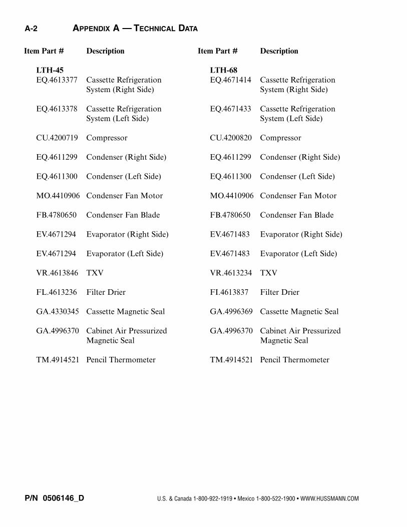
LTH-45EQ.4613377 Cassette Refrigeration
System (Right Side)
EQ.4613378 Cassette RefrigerationSystem (Left Side)
CU.4200719 Compressor
EQ.4611299 Condenser (Right Side)
EQ.4611300 Condenser (Left Side)
MO.4410906 Condenser Fan Motor
FB.4780650 Condenser Fan Blade
EV.4671294 Evaporator (Right Side)
EV.4671294 Evaporator (Left Side)
VR.4613846 TXV
FL.4613236 Filter Drier
GA.4330345 Cassette Magnetic Seal
GA.4996370 Cabinet Air Pressurized Magnetic Seal
TM.4914521 Pencil Thermometer
Item Part # Description
LTH-68EQ.4671414 Cassette Refrigeration
System (Right Side)
EQ.4671433 Cassette RefrigerationSystem (Left Side)
CU.4200820 Compressor
EQ.4611299 Condenser (Right Side)
EQ.4611300 Condenser (Left Side)
MO.4410906 Condenser Fan Motor
FB.4780650 Condenser Fan Blade
EV.4671483 Evaporator (Right Side)
EV.4671483 Evaporator (Left Side)
VR.4613234 TXV
FI.4613837 Filter Drier
GA.4996369 Cassette Magnetic Seal
GA.4996370 Cabinet Air Pressurized Magnetic Seal
TM.4914521 Pencil Thermometer
P/N 0506146_D U.S. & Canada 1-800-922-1919 • Mexico 1-800-522-1900 • WWW.HUSSMANN.COM
A-2 APPENDIX A — TECHNICAL DATA
Item Part # Description
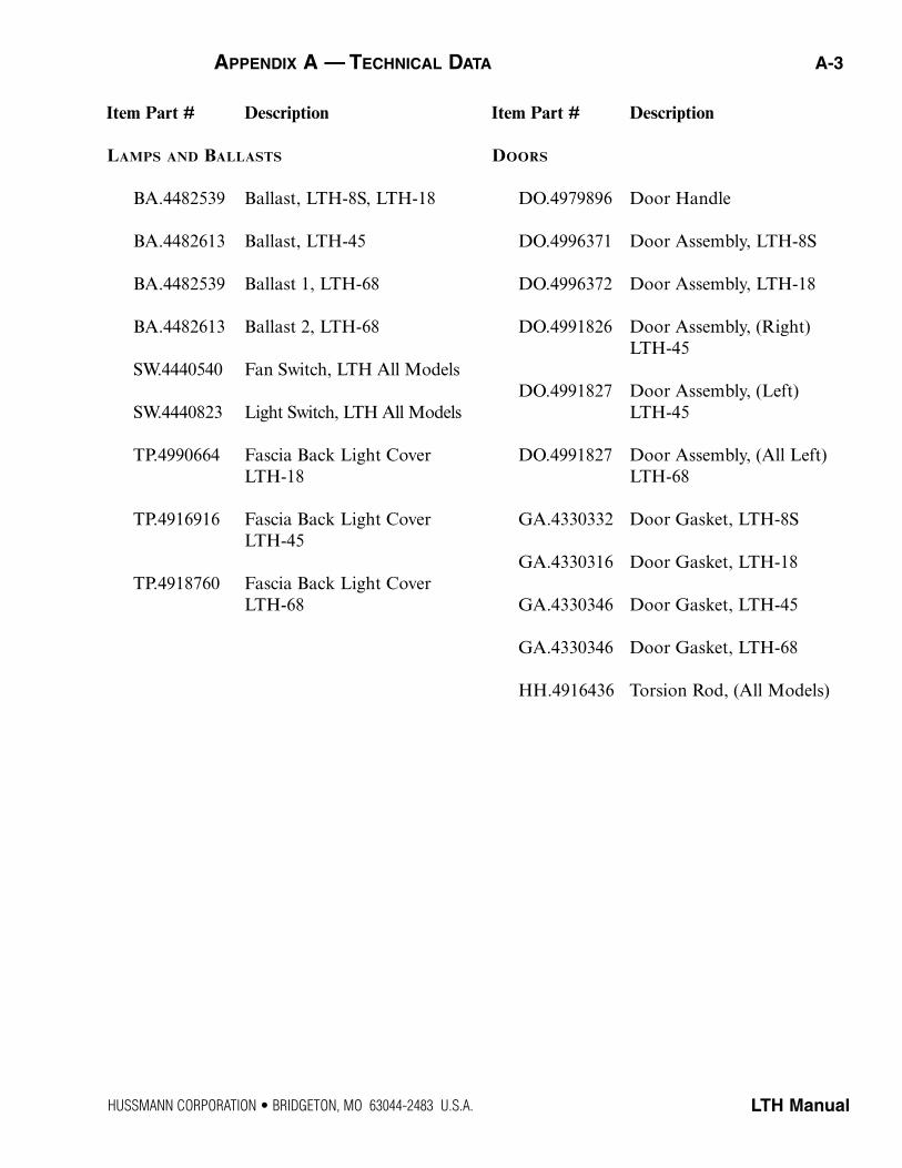
LAMPS AND BALLASTS
BA.4482539 Ballast, LTH-8S, LTH-18
BA.4482613 Ballast, LTH-45
BA.4482539 Ballast 1, LTH-68
BA.4482613 Ballast 2, LTH-68
SW.4440540 Fan Switch, LTH All Models
SW.4440823 Light Switch, LTH All Models
TP.4990664 Fascia Back Light CoverLTH-18
TP.4916916 Fascia Back Light CoverLTH-45
TP.4918760 Fascia Back Light CoverLTH-68
Item Part # Description
DOORS
DO.4979896 Door Handle
DO.4996371 Door Assembly, LTH-8S
DO.4996372 Door Assembly, LTH-18
DO.4991826 Door Assembly, (Right) LTH-45
DO.4991827 Door Assembly, (Left) LTH-45
DO.4991827 Door Assembly, (All Left) LTH-68
GA.4330332 Door Gasket, LTH-8S
GA.4330316 Door Gasket, LTH-18
GA.4330346 Door Gasket, LTH-45
GA.4330346 Door Gasket, LTH-68
HH.4916436 Torsion Rod, (All Models)
LTH Manual
APPENDIX A — TECHNICAL DATA A-3
HUSSMANN CORPORATION • BRIDGETON, MO 63044-2483 U.S.A.
P/N 0506146_D U.S. & Canada 1-800-922-1919 • Mexico 1-800-522-1900 • WWW.HUSSMANN.COM
A-4 APPENDIX A — TECHNICAL DATA
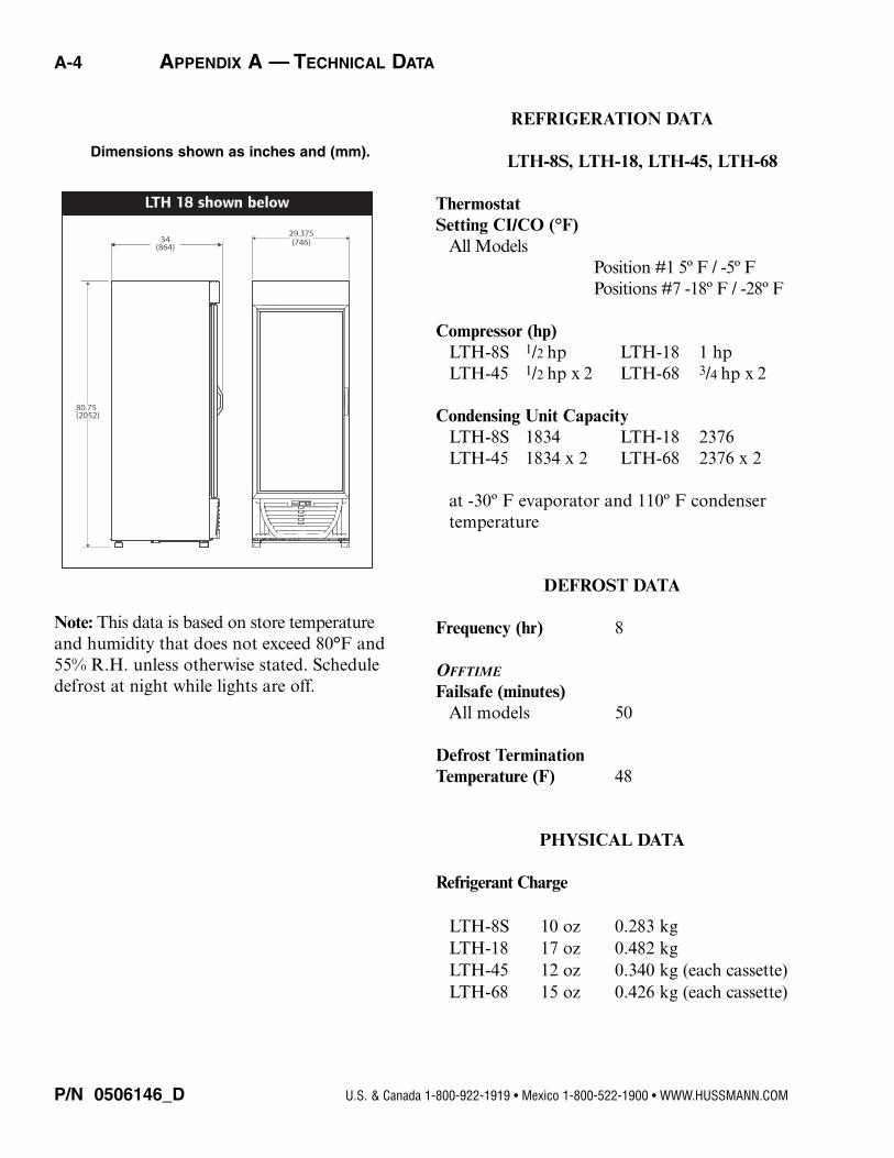
REFRIGERATION DATA
LTH-8S, LTH-18, LTH-45, LTH-68
ThermostatSetting CI/CO (°F)
All ModelsPosition #1 5º F / -5º FPositions #7 -18º F / -28º F
Compressor (hp)LTH-8S 1/2 hp LTH-18 1 hpLTH-45 1/2 hp x 2 LTH-68 3/4 hp x 2
Condensing Unit CapacityLTH-8S 1834 LTH-18 2376LTH-45 1834 x 2 LTH-68 2376 x 2
at -30º F evaporator and 110º F condenser temperature
DEFROST DATA
Frequency (hr) 8
OFFTIME
Failsafe (minutes)All models 50
Defrost TerminationTemperature (F) 48
PHYSICAL DATA
Refrigerant Charge
LTH-8S 10 oz 0.283 kg LTH-18 17 oz 0.482 kgLTH-45 12 oz 0.340 kg (each cassette)LTH-68 15 oz 0.426 kg (each cassette)
Dimensions shown as inches and (mm).
Note: This data is based on store temperatureand humidity that does not exceed 80°F and55% R.H. unless otherwise stated. Scheduledefrost at night while lights are off.
LTH ManualHUSSMANN CORPORATION • BRIDGETON, MO 63044-2483 U.S.A.
APPENDIX A — TECHNICAL DATA A-5
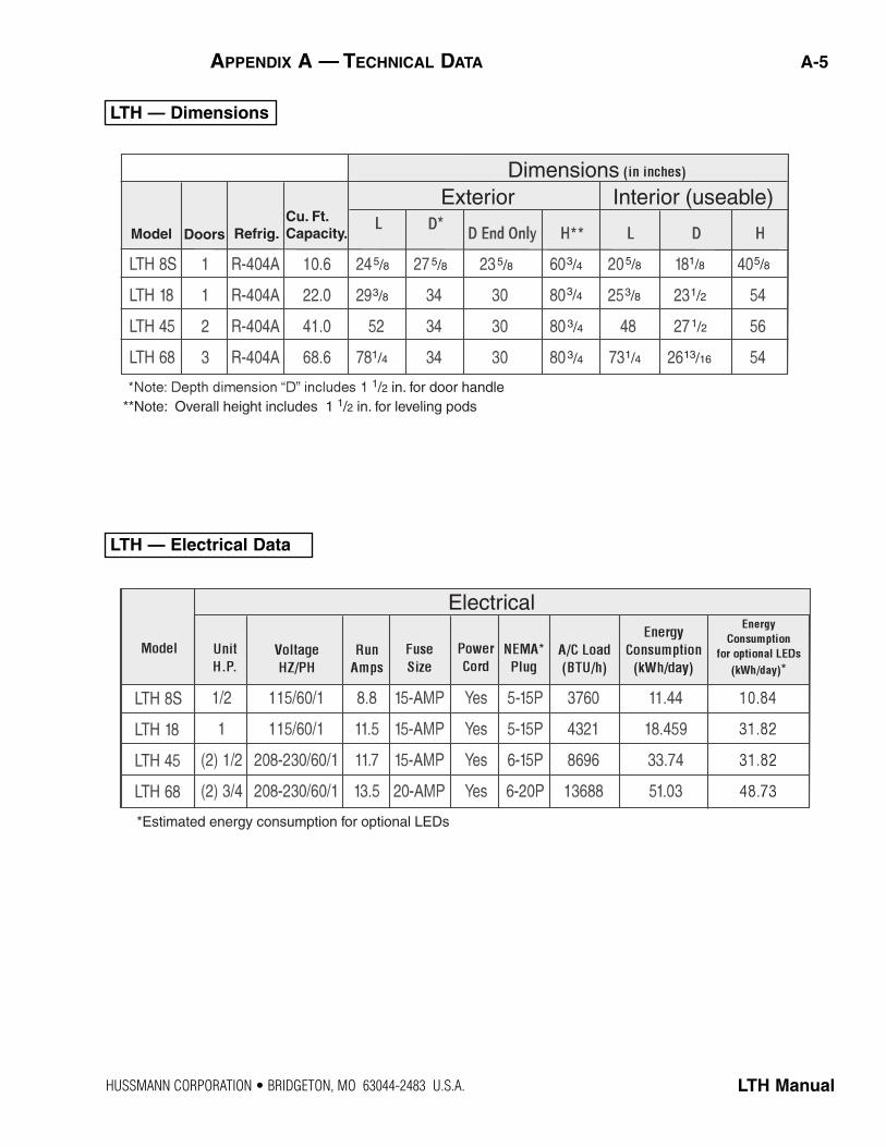
DimensionsExterior Interior (useable)
1/2 in. for door handle**Note: Overall height includes 1 1/2 in. for leveling pods
Model Doors Refrig.Cu. Ft. Capacity.
5/8 5/8 5/8 5/8 5/8 3/4
3/4
3/4
3/4 1/2
1/2
1/8
13/16 1/4
3/8 3/8
1/4
Electrical
**
*Estimated energy consumption for optional LEDs
LTH — Dimensions
LTH — Electrical Data
P/N 0506146_D U.S. & Canada 1-800-922-1919 • Mexico 1-800-522-1900 • WWW.HUSSMANN.COM
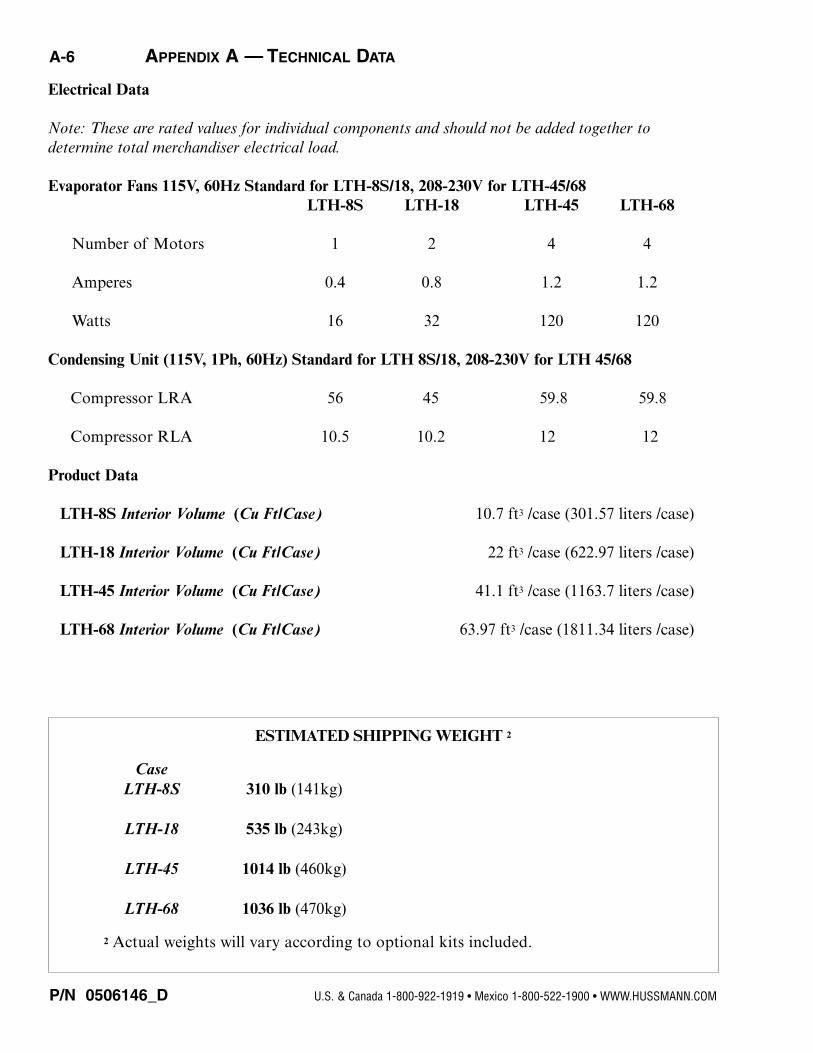
Electrical Data
Note: These are rated values for individual components and should not be added together to determine total merchandiser electrical load.
Evaporator Fans 115V, 60Hz Standard for LTH-8S/18, 208-230V for LTH-45/68LTH-8S LTH-18 LTH-45 LTH-68
Number of Motors 1 2 4 4
Amperes 0.4 0.8 1.2 1.2
Watts 16 32 120 120
Condensing Unit (115V, 1Ph, 60Hz) Standard for LTH 8S/18, 208-230V for LTH 45/68
Compressor LRA 56 45 59.8 59.8
Compressor RLA 10.5 10.2 12 12
Product Data
LTH-8S Interior Volume (Cu Ft/Case) 10.7 ft3 /case (301.57 liters /case)
LTH-18 Interior Volume (Cu Ft/Case) 22 ft3 /case (622.97 liters /case)
LTH-45 Interior Volume (Cu Ft/Case) 41.1 ft3 /case (1163.7 liters /case)
LTH-68 Interior Volume (Cu Ft/Case) 63.97 ft3 /case (1811.34 liters /case)
ESTIMATED SHIPPING WEIGHT 2
CaseLTH-8S 310 lb (141kg)
LTH-18 535 lb (243kg)
LTH-45 1014 lb (460kg)
LTH-68 1036 lb (470kg)
2 Actual weights will vary according to optional kits included.
A-6 APPENDIX A — TECHNICAL DATA
LTH ManualHUSSMANN CORPORATION • BRIDGETON, MO 63044-2483 U.S.A. • WWW.HUSSMANN.COM
W
GRAY
W
115VAC-60HZ-1PH
L1N
BK
W
LOW VOLTAGE TRANSFORMER
BK
SAFE-NET I
CONTROL
W BK
BK
N
ANTI-SWEAT
LIGHTS/COMP
115/230 VAC
DEFROST
FANS
NE
UT
RA
L
BK
DIGITAL
DISPLAY
DEFROST
RELAY SENSORS
DEFROST
TERM.
DISCHARGE
CENTER
L1
Y
Y
DOOR SWITCH
EVAP. FAN
DEFROST HTR. LIMIT
ONLY WHEN REVERSING
COND. FAN IS USEDW
COMPRESSOR
RELAY
BK
N
RELAY
W
START CAP.
RUN CAP.W
BK
R
1 2
4 5
OVERLOAD
S R
C
NO
BK
L1
COND. FAN
ONLY WHEN REVERSING
COND. FAN IS USED
W
BK
COMPRESSOR
LIGHT
SWITCH
INTERIOR LAMPBALLAST
DOOR PERIMETER HEATER
W BK
W BK
(MODELS WITH
HEATED GLASS
ONLY)SAFE-NET I
ONLY
SAFE-NET III
ONLY
FRAME HEATER
HEATED GLASS
Model LTH-8S
Model LTH-8S
W
L1N
BK
115VAC-60HZ-1PH
N
Y
DOOR SWITCH
EVAP. FAN
DEFROST HTR. LIMIT
DIGITAL
DISPLAY
L1
C
NO
NC
REVERSE FAN
RELAY
DIODE
W
BK
BK
BK
Y
SENSOR-DEFROST TERM.
SENSOR-CONTROL101 2 3 4 5 6 7 8 9 11
LINE
DEF FAN COMP.
SAFE-NET III CONTROL
BR
BK
OR
BL
BK BK
W
Model LTH-8S
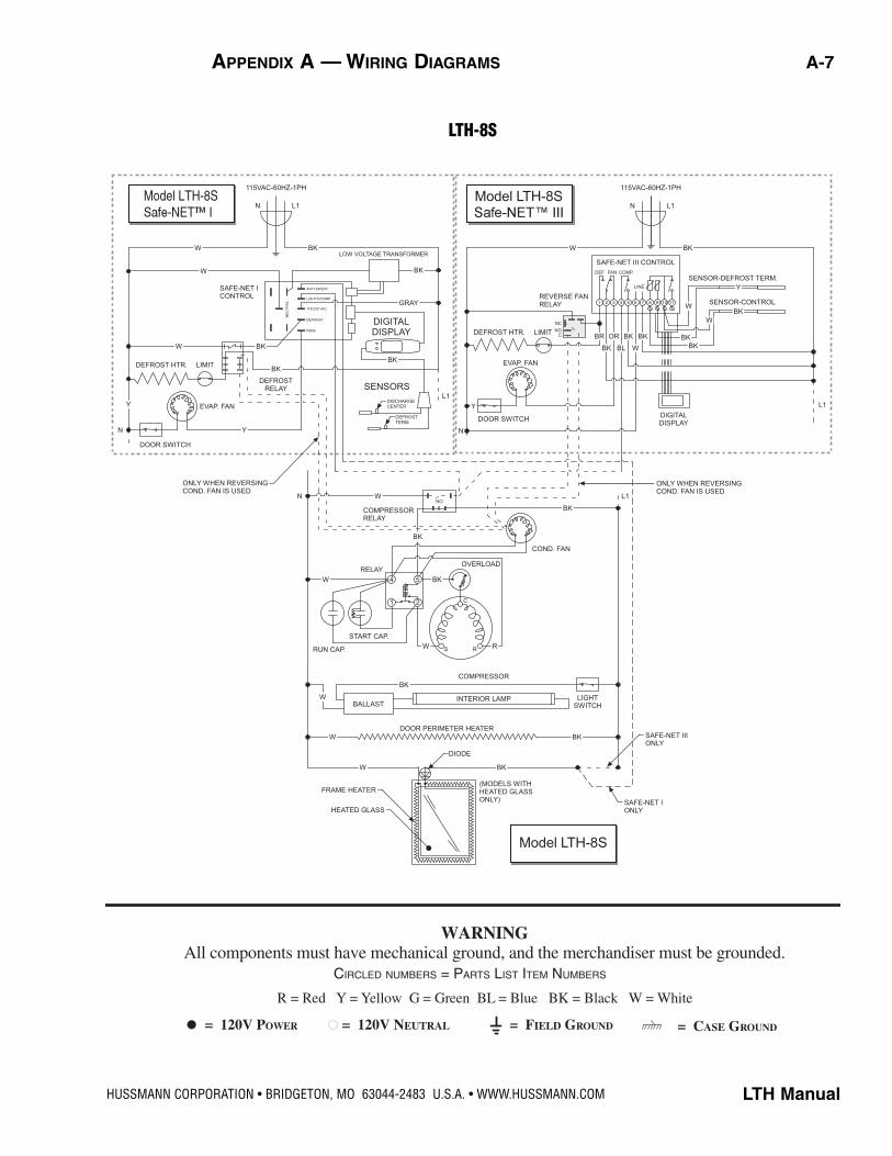
LTH-8S
R = Red Y = Yellow G = Green BL = Blue BK = Black W = White
= 120V POWER = 120V NEUTRAL = FIELD GROUND = CASE GROUND
WARNING All components must have mechanical ground, and the merchandiser must be grounded.
CIRCLED NUMBERS = PARTS LIST ITEM NUMBERS
APPENDIX A — WIRING DIAGRAMS A-7
P/N 0506146_D U.S. & Canada 1-800-922-1919 • Mexico 1-800-522-1900 • WWW.HUSSMANN.COM
A-8 APPENDIX A — WIRING DIAGRAMSA- APPENDIX A — WIRING DIAGRAMS
W
W
SAFE-NET I
CONTROL
115VAC-60HZ-1PH
L1N
ANTI-SWEAT
LIGHTS/COMP
115/230 VAC
DEFROST
FANS
NE
UT
RA
L
GRAY
BKLOW VOLTAGE TRANSFORMER
BK
BK
DIGITAL
DISPLAY
SENSORS
DEFROST
TERM.
DISCHARGE
CENTER
L1
N
DEFROST HTR.
Y
DOOR SWITCH
EVAP. FANS
W BK
BK
N
DEFROST
RELAY
Y
YDOOR SWITCH
EVAP. FANS
DEFROST HTR. LIMIT
WCOMPRESSOR
RELAY
NNO
W
Model LTH-18
I
Model LTH-18
III
Model LTH-18
DIGITAL
DISPLAY
L1
L1N
115VAC-60HZ-1PH
W BK
SAFE-NET III CONTROL
CNO
NC
LIMIT
FAN DELAY SW.
WBK
Y
SENSOR-DEFROST TERM.
SENSOR-CONTROL
W
BR
BK
OR
BL
BK BK
W BK
BK
LINE
DEF FAN COMP.
101 2 3 4 5 6 7 8 9 11
ONLY WHEN REVERSING COND. FAN IS USED
ONLY WHEN REVERSING
COND. FAN IS USED
STANDARD AND
REVERSING COND.
FAN IS USED
W
SAFE-NET I
ONLY
SAFE-NET III
ONLY
SAFE-NET I
ONLY
BK
LIGHT
SWITCH
BK
(MODELS WITH
HEATED GLASS
ONLY)
BK
BK
DIODE
DOOR PERIMETER HEATER
COMPRESSOR
INTERIOR LAMP
INTERIOR LAMP
FRAME HEATER
HEATED GLASS
BALLAST
BALLAST
W
W
W
W
SIGN LAMP
LIMIT
RELAY
START CAP.RUN
CAP.
1 2
4 5
W
BK
S R
C
R
OVERLOAD
BKREVERSING
COND. FAN
L1
BK
SMOOTH BK CW
RIBBED W COMMON
ONLY WHEN REVERSING
COND. FAN IS USED
REVERSING RELAY
CNONC
CENTER-CW
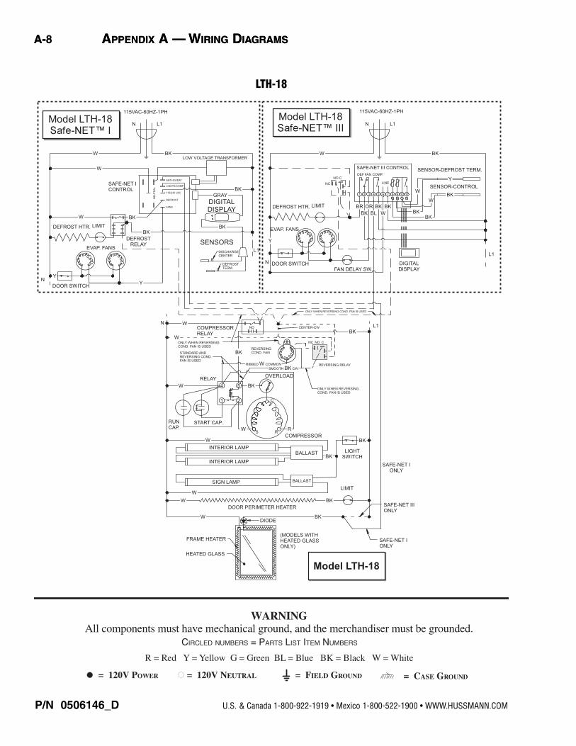
LTH-18
R = Red Y = Yellow G = Green BL = Blue BK = Black W = White
= 120V POWER = 120V NEUTRAL = FIELD GROUND = CASE GROUND
WARNING All components must have mechanical ground, and the merchandiser must be grounded.
CIRCLED NUMBERS = PARTS LIST ITEM NUMBERS
LTH ManualHUSSMANN CORPORATION • BRIDGETON, MO 63044-2483 U.S.A. • WWW.HUSSMANN.COM
Models LTH-45
and LTH-68
W
W
W
W
BK
BK
BK
BK
BK
DOOR PERIMETER HEATERS (2-LTH-5, 3-LTH-68)
DIODE
FRAME HEATER
HEATED GLASS
MODELS WITH
HEATED GLASS
ONLY.)
2-DOORS ON
LTH-453-DOORS ON
LTH-68
SAFE-NET III
ONLY
SAFE-NET I
ONLY
CASSETTE-LEFT
W
CASSETTE-RIGHT
RUN
CAP.START CAP.
W
COMPRESSOR
WS R
R
C
OVERLOAD
4 5
1 2
SIGN LAMP-LTH-68
SIGN LAMP-LTH-68
INTERIOR LAMP
INTERIOR LAMP
INTERIOR LAMP
SIGN LAMP-45 INTERIOR LAMP-68
BALLAST
BALLAST
BK
BKBK
LIGHT
SWITCH
DEFROST HTR. LIMIT
NO
TIME DELAY
COMPRESSOR RELAY
T
2
3
ONLY WHEN REVERSING
COND. FAN IS USED
NC NO C
STANDARD AND REVERSING
COND. FAN
ONLY WHEN STANDARD
COND. FAN IS USED
RELAY
W
RUN
CAP.
START CAP.
COMPRESSOR
WS R
R
C
OVERLOAD
4 5
1 2
ONLY WHEN REVERSING
COND. FAN IS USED
DEFROST
RELAY
DEFROST HTR. LIMIT
REVERSING
RELAY
CE
NT
ER
-CC
W
RIBBED W COMMON
REVERSING
COND. FAN
RELAY
W
BK
BK
W
SMOOTH BK CW
COMPRESSOR RELAY NO
BK
BK
EVAP. FANS
W
DOOR SWITCHES
EVAP. FANS
NO NO
L1
Y
BK
BK
SMOOTH BK CW
REVERSING
COND. FAN
RIBBED W COMMON
ONLY WHEN
STANDARD
COND. FAN
IS USED
BK
L2
208/230VAC-60HZ-1PH
L2 L1
W
W
SAFE-NET I
CONTROL
L2
LOW VOLTAGE TRANSFORMER
ANTI-SWEAT
LIGHTS/COMP.
DEFROST
115/230 VAC
FANSN
EU
TR
AL
DIGITAL DISPLAY
SENSORS
DISCHARGE
CENTER
DEFROST
TERM.
L1
GREY
Model LTH-45
& LTH-68 with
L2
208/230VAC-60HZ-1PH
L2 L1
Model LTH-45
& LTH-68 with
SAFE-NET III CONTROL
W
ORBR
BL
BK
BK
BK
W
W
SENSOR-DEFROST TERM.
SENSOR-CONTROL
Y
FAN DELAY
SW.
DIGITAL
DISPLAY
L1
BK
BK
BK
BKBK
BK
BK
W
1 111098765432
CE
NT
ER
-CC
W
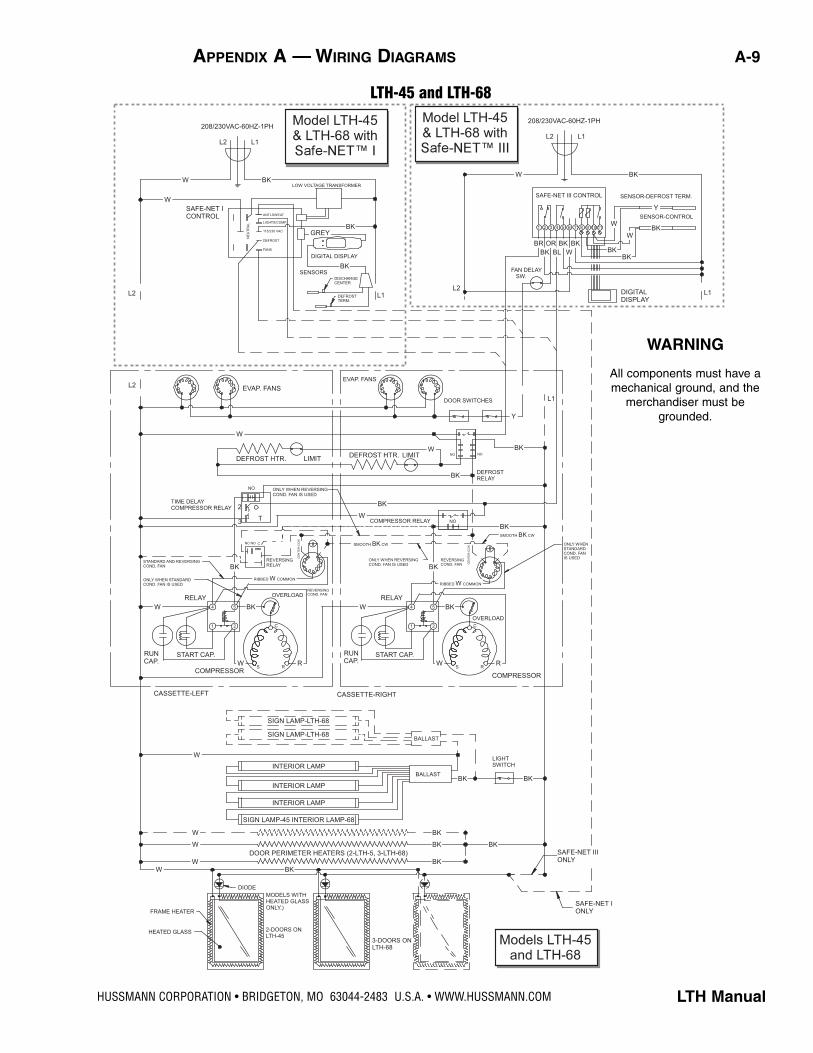
LTH-45 and LTH-68
WARNING
All components must have amechanical ground, and the
merchandiser must begrounded.
APPENDIX A — WIRING DIAGRAMS A-9
P/N 0506146_D U.S. & Canada 1-800-922-1919 • Mexico 1-800-522-1900 • WWW.HUSSMANN.COM
A-10 APPENDIX A — WIRING DIAGRAMS
W
GRAY
W
115VAC-60HZ-1PH
L1N
BK
W
LOW VOLTAGE TRANSFORMER
BK
SAFE-NET I
CONTROL
W BK
BK
N
ANTI-SWEAT
LIGHTS/COMP
115/230 VAC
DEFROST
FANS
NE
UT
RA
L
BK
DIGITAL
DISPLAY
DEFROST
RELAY SENSORS
DEFROST
TERM.
DISCHARGE
CENTER
L1
Y
Y
DOOR SWITCH
EVAP. FAN
DEFROST HTR. LIMIT
ONLY WHEN REVERSING
COND. FAN IS USEDW
COMPRESSOR
RELAY
BK
N
RELAY
W
START CAP.
RUN CAP.W
BK
R
1 2
4 5
OVERLOAD
S R
C
NO
BK
L1
COND. FAN
ONLY WHEN REVERSING
COND. FAN IS USED
W
BK
COMPRESSOR
LIGHT
SWITCHINTERIOR LEDPOWER
SUPPLY
DOOR PERIMETER HEATER
W BK
W BK
(MODELS WITH
HEATED GLASS
ONLY)SAFE-NET I
ONLY
SAFE-NET III
ONLY
FRAME HEATER
HEATED GLASS
Model LTH-8S
Model LTH-8S
W
L1N
BK
115VAC-60HZ-1PH
N
Y
DOOR SWITCH
EVAP. FAN
DEFROST HTR. LIMIT
DIGITAL
DISPLAY
L1
C
NO
NC
REVERSE FAN
RELAY
DIODE
W
BK
BK
BK
Y
SENSOR-DEFROST TERM.
SENSOR-CONTROL101 2 3 4 5 6 7 8 9 11
LINE
DEF FAN COMP.
SAFE-NET III CONTROL
BR
BK
OR
BL
BK BK
W
Model LTH-8S
BLR
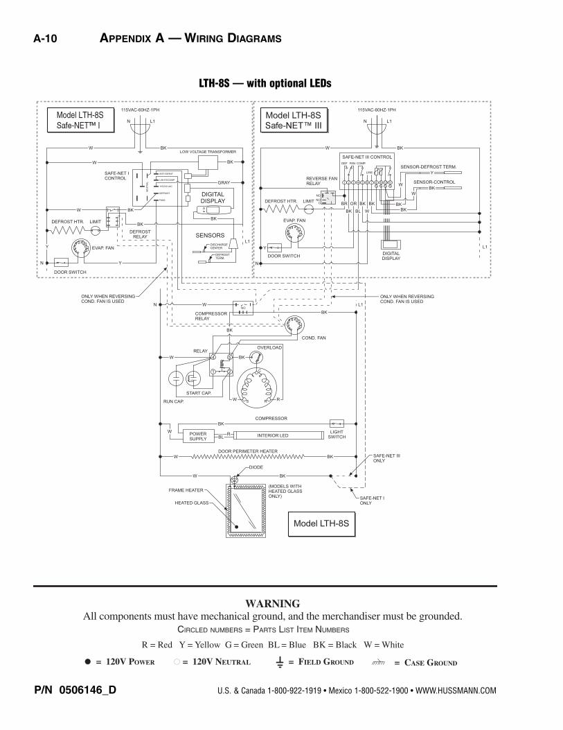
LTH-8S — with optional LEDs
R = Red Y = Yellow G = Green BL = Blue BK = Black W = White
= 120V POWER = 120V NEUTRAL = FIELD GROUND = CASE GROUND
WARNING All components must have mechanical ground, and the merchandiser must be grounded.
CIRCLED NUMBERS = PARTS LIST ITEM NUMBERS
LTH ManualHUSSMANN CORPORATION • BRIDGETON, MO 63044-2483 U.S.A. • WWW.HUSSMANN.COM
BLR
RBL
RBL
W
W
SAFE-NET I
CONTROL
115VAC-60HZ-1PH
L1N
ANTI-SWEAT
LIGHTS/COMP
115/230 VAC
DEFROST
FANS
NE
UT
RA
L
GRAY
BKLOW VOLTAGE TRANSFORMER
BK
BK
DIGITAL
DISPLAY
SENSORS
DEFROST
TERM.
DISCHARGE
CENTER
L1
N
DEFROST HTR.
Y
DOOR SWITCH
EVAP. FANS
W BK
BK
N
DEFROST
RELAY
Y
YDOOR SWITCH
EVAP. FANS
DEFROST HTR. LIMIT
WCOMPRESSOR
RELAY
NNO
W
Model LTH-18
I
Model LTH-18
III
Model LTH-18
DIGITAL
DISPLAY
L1
L1N
115VAC-60HZ-1PH
W BK
SAFE-NET III CONTROL
CNO
NC
LIMIT
FAN DELAY SW.
WBK
Y
SENSOR-DEFROST TERM.
SENSOR-CONTROL
W
BR
BK
OR
BL
BK BK
W BK
BK
LINE
DEF FAN COMP.
101 2 3 4 5 6 7 8 9 11
ONLY WHEN REVERSING COND. FAN IS USED
ONLY WHEN REVERSING
COND. FAN IS USED
STANDARD AND
REVERSING COND.
FAN IS USED
W
SAFE-NET I
ONLY
SAFE-NET III
ONLY
SAFE-NET I
ONLY
BK
LIGHT
SWITCH
BK
(MODELS WITH
HEATED GLASS
ONLY)
BK
BK
DIODE
DOOR PERIMETER HEATER
COMPRESSOR
INTERIOR LED
INTERIOR LED
FRAME HEATER
HEATED GLASS
POWER
SUPPLY
W
W
W
SIGN LED
LIMIT
RELAY
START CAP.RUN
CAP.
1 2
4 5
W
BK
S R
C
R
OVERLOAD
BKREVERSING
COND. FAN
L1
BK
SMOOTH BK CW
RIBBED W COMMON
ONLY WHEN REVERSING
COND. FAN IS USED
REVERSING RELAY
CNONC
CENTER-CW
POWER
SUPPLY
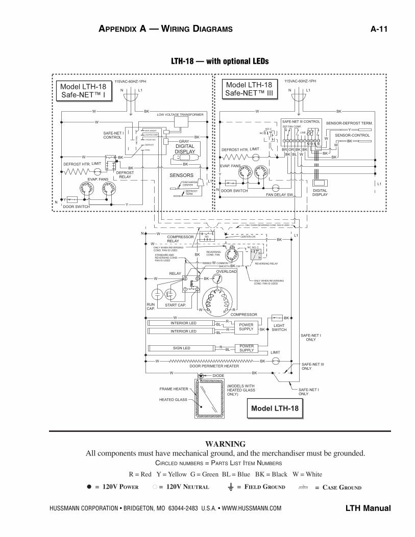
LTH-18 — with optional LEDs
R = Red Y = Yellow G = Green BL = Blue BK = Black W = White
= 120V POWER = 120V NEUTRAL = FIELD GROUND = CASE GROUND
WARNING All components must have mechanical ground, and the merchandiser must be grounded.
CIRCLED NUMBERS = PARTS LIST ITEM NUMBERS
APPENDIX A — WIRING DIAGRAMS A-11
P/N 0506146_D U.S. & Canada 1-800-922-1919 • Mexico 1-800-522-1900 • WWW.HUSSMANN.COM
A-12 APPENDIX A — WIRING DIAGRAMS
Models LTH-45
and LTH-68
W
W
W
W
BK
BK
BK
BK
BK
DOOR PERIMETER HEATERS (2-LTH-5, 3-LTH-68)
DIODE
FRAME HEATER
HEATED GLASS
MODELS WITH
HEATED GLASS
ONLY.)
2-DOORS ON
LTH-453-DOORS ON
LTH-68
SAFE-NET III
ONLY
SAFE-NET I
ONLY
CASSETTE-LEFT
W
CASSETTE-RIGHT
RUN
CAP.START CAP.
W
COMPRESSOR
WS R
R
C
OVERLOAD
4 5
1 2
SIGN LED-LTH-68
SIGN LED-LTH-68
INTERIOR LED
INTERIOR LED
INTERIOR LED
SIGN LED-45 INTERIOR LED-68
POWER
SUPPLY
POWER
SUPPLY
BK
BKBK
LIGHT
SWITCH
DEFROST HTR. LIMIT
NO
TIME DELAY
COMPRESSOR RELAY
T
2
3
ONLY WHEN REVERSING
COND. FAN IS USED
NC NO C
STANDARD AND REVERSING
COND. FAN
ONLY WHEN STANDARD
COND. FAN IS USED
RELAY
W
RUN
CAP.
START CAP.
COMPRESSOR
WS R
R
C
OVERLOAD
4 5
1 2
ONLY WHEN REVERSING
COND. FAN IS USED
DEFROST
RELAY
DEFROST HTR. LIMIT
REVERSING
RELAY
CE
NT
ER
-CC
W
RIBBED W COMMON
REVERSING
COND. FAN
RELAY
W
BK
BK
W
SMOOTH BK CW
COMPRESSOR RELAY NO
BK
BK
EVAP. FANS
W
DOOR SWITCHES
EVAP. FANS
NO NO
L1
Y
BK
BK
SMOOTH BK CW
REVERSING
COND. FAN
RIBBED W COMMON
ONLY WHEN
STANDARD
COND. FAN
IS USED
BK
L2
208/230VAC-60HZ-1PH
L2 L1
W
W
SAFE-NET I
CONTROL
L2
LOW VOLTAGE TRANSFORMER
ANTI-SWEAT
LIGHTS/COMP.
DEFROST
115/230 VAC
FANS
NE
UT
RA
L
DIGITAL DISPLAY
SENSORS
DISCHARGE
CENTER
DEFROST
TERM.
L1
GREY
Model LTH-45
& LTH-68 with
L2
208/230VAC-60HZ-1PH
L2 L1
Model LTH-45
& LTH-68 with
SAFE-NET III CONTROL
W
ORBR
BL
BK
BK
BK
W
W
SENSOR-DEFROST TERM.
SENSOR-CONTROL
Y
FAN DELAY
SW.
DIGITAL
DISPLAY
L1
BK
BK
BK
BKBK
BK
BK
W
1 111098765432
CE
NT
ER
-CC
W
R
BL
R
R
R
RBL
BL
BL
BL
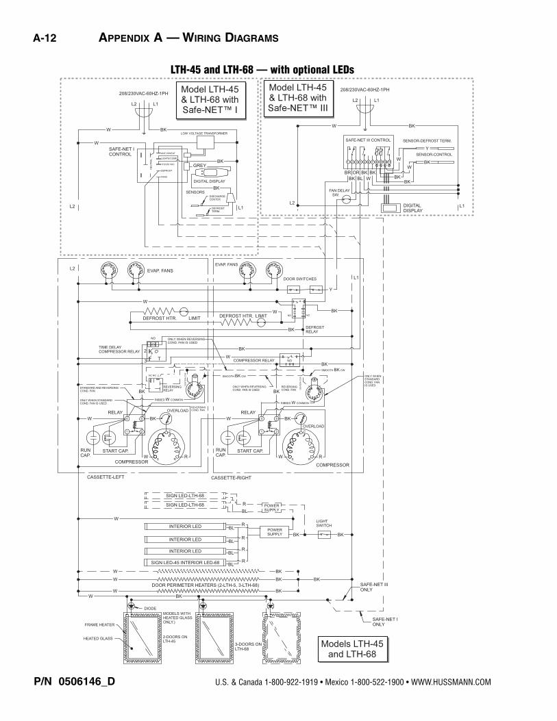
LTH-45 and LTH-68 — with optional LEDs
®
To obtain warranty information or other support, contact your
Hussmann representative.Please include the model and serial number of the product.
U.S. & Canada 1-800-922-1919 • Mexico 1-800-522-1900www.hussmann.com
Hussmann Corporation, Corporate Headquarters: Bridgeton, Missouri, U.S.A. 63044-2483 01 July 2008

Hussmann Corporation12999 St. Charles Rock RoadBridgeton, MO 63044-2483www.hussmann.com
Recommended