82 Power Distribution product guide eatoncorp.com.au December 2017
IEC MCCB
Low Voltage Circuit Protection & Switchgear
1. Switch-disconnetor, circuit-breaker, circuit-breaker for North America; Moulded case switches for North America
2. IP2X protection against contact with a finger
3. Terminal cover, knockout
4. Terminal cover
5. IP2X protection against contact with a finger
6. Tunnel terminal
7. Box terminals
8. Control circuit terminal
9. Connection width extension
10. Plug-in and withdrawable unit
11. Adapter plate
12. Busbar adapters
13. Connection on rear
14. Spacers
15. Standard auxiliary contact (HIV), trip-indicating auxiliary switch (HIA), voltage release
16. Measuring and communication module
17. Residual-current protection device
18. Rear driver
19. Main switch rotary handle for side panel mounting
20. Door coupling rotary handle
21. Extension shaft
22. Door coupling rotary handle
23. Rotary handle
24. Insulating surrounds
25. External warning plate/marking plate
26. Remote operator
27. Toggle lever locking device
28. Side operator handle
29. Mechanical interlock
30. Display
31. Data management interface (DMI module)
32. PROFIBUS-DP interface
33. NZM communication module
34. NZM communication module for Smartwire-DT
35. Early-make auxiliary contacts
36. Delay unit for undervoltage releases
37. Insulated enclosures
System overview - Circuit-breakers, Switch-disconnectors
NZM range
36
3
4
1
56
7
10
11
13 14
1518
17
16
29
28
37
27
30
26
24 25
2320
19
22
21
12
89
2
35
31 32
33
34
83Power Distribution product guide eatoncorp.com.au December 2017
IEC MCCB
4-pole circuit-breaker
1-pole 3-pole circuit-breaker
Low Voltage Circuit Protection & Switchgear
NZM range up to 1600 A – New ideas for better circuit-breakers
The new Eaton circuit-breakers cover a range from 15 to 1600 A with just four frame sizes. And they are optimally matched to one another. The wide application spectrum covers every requirement as Eaton has closely examined what every customer needs and implemented the appropriate solutions. Outstanding, for example, is the continuous switching power range – which extends from the smallest to the largest circuit-breaker or the modular system which can be matched without difficulty to suit the specific application. Thus, the circuit-breakers can be used universally – from the smallest of service distribution boards, to machine controls or motor starter combinations, up to large energy distribution systems with a short-circuit breaking capacity of up to 150 kA.
Excellent under load – Switch-disconnector’s for safe switching under load
Even under load conditions the Eaton switch-disconnector operates safely. The reason: the 3- or 4-pole snap-action closing mechanism which is also applied with circuit-breakers.
That’s why the rated short time withstand current is so high and can handle currents up to 150 000 A. The long lifetime with up to 7 500 switching operations in AC3 mode enables usage as a motor switch, in order to switch large motors during operation. Application as a main switch with an emergency-stop function via a remote pushbutton is easily implemented in conjunction with the double early-make auxiliary contacts and undervoltage release. This in conjunction with the UL/CSA approvals is a prerequisite for use in process and processing machines which are destined for export.
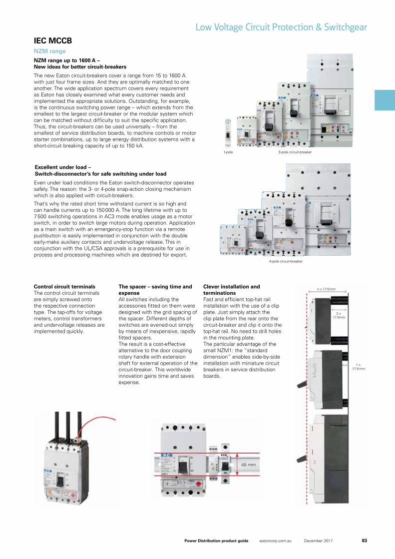
Control circuit terminalsThe control circuit terminals are simply screwed onto the respective connection type. The tap-offs for voltage meters, control transformers and undervoltage releases are implemented quickly.
The spacer – saving time and expenseAll switches including the accessories fitted on them were designed with the grid spacing of the spacer. Different depths of switches are evened-out simply by means of inexpensive, rapidly fitted spacers.The result is a cost-effective alternative to the door coupling rotary handle with extension shaft for external operation of the circuit-breaker. This worldwide innovation gains time and saves expense.
Clever installation and terminationsFast and efficient top-hat rail installation with the use of a clip plate. Just simply attach the clip plate from the rear onto the circuit-breaker and clip it onto the top-hat rail. No need to drill holes in the mounting plate.The particular advantage of the small NZM1: the “standard dimension” enables side-by-side installation with miniature circuit breakers in service distribution boards.
NZM range
84 Power Distribution product guide eatoncorp.com.au December 2017
IEC MCCB
Low Voltage Circuit Protection & Switchgear
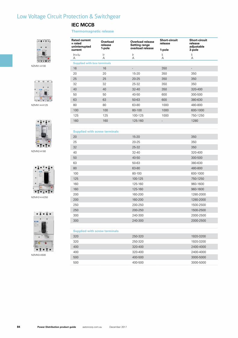
Controlling & switching devicesThermomagnetic release
Rated current = rated uninterrupted current
Overload release 1-pole
Overload releaseSetting range overload release
Short-circuit release
1-pole
Short-circuit release adjustable3-pole
ln=luA
IrA
lrA
liA
liA
Supplied with box terminals
16 16 - 350 -
20 20 15-20 350 350
25 25 20-25 350 350
32 32 25-32 350 350
40 40 32-40 350 320-400
50 50 40-50 600 300-500
63 63 50-63 600 380-630
80 80 63-80 1000 480-800
100 100 80-100 1000 600-1000
125 125 100-125 1000 750-1250
160 160 125-160 - 1280
Supplied with screw terminals
20 15-20 350
25 20-25 350
32 25-32 350
40 32-40 320-400
50 40-50 300-500
63 50-63 380-630
80 63-80 480-800
100 80-100 600-1000
125 100-125 750-1250
160 125-160 960-1600
160 125-160 960-1600
200 160-200 1280-2000
200 160-200 1280-2000
250 200-250 1500-2500
250 200-250 1500-2500
300 240-300 2000-2500
300 240-300 2000-2500
Supplied with screw terminals
320 250-320 1920-3200
320 250-320 1920-3200
400 320-400 2400-4000
400 320-400 2400-4000
500 400-500 3000-5000
500 400-500 3000-5000
NZMN3-A500
NZMH2-4-A250
NZMN2-A160
NZMN1-4-A125
NZMN1-A100
85Power Distribution product guide eatoncorp.com.au December 2017
IEC MCCB
Low Voltage Circuit Protection & Switchgear
Controlling & switching devices
Applies for NZM1
Applies for NZM2 and NZM3
60% release on neutral pole
Max. DC voltage rating 500Vdc ICU / ICS 15/15kA
Max. DC voltage rating 500Vdc ICU / ICS 30/30kA
Max. DC voltage rating 750Vdc ICU / ICS 30/7.5kA
Max. DC voltage rating 750Vdc ICU / ICS 60/15kA
Max. DC voltage rating 750Vdc ICU / ICS 30/30kA
Max. DC voltage rating 750Vdc ICU / ICS 70/70kA
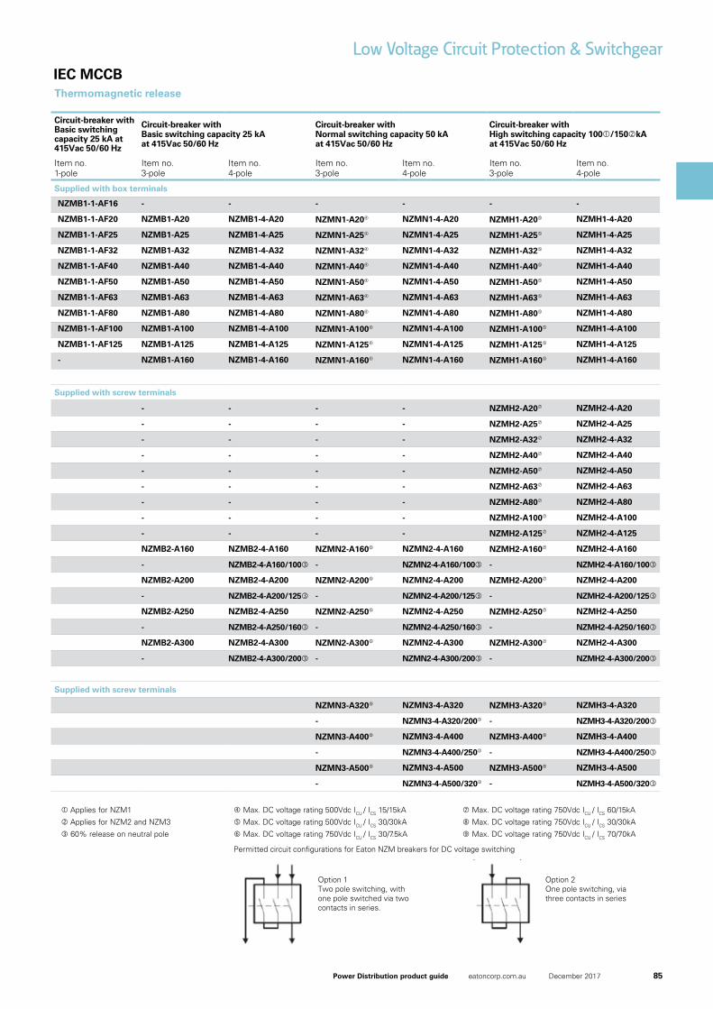
Thermomagnetic release
Circuit-breaker with Basic switching capacity 25 kA at 415Vac 50/60 Hz
Circuit-breaker withBasic switching capacity 25 kAat 415Vac 50/60 Hz
Circuit-breaker withNormal switching capacity 50 kAat 415Vac 50/60 Hz
Circuit-breaker withHigh switching capacity 100/150kA at 415Vac 50/60 Hz
Item no.1-pole
Item no. 3-pole
Item no. 4-pole
Item no.3-pole
Item no.4-pole
Item no.3-pole
Item no.4-pole
Supplied with box terminals
NZMB1-1-AF16 - - - - - -
NZMB1-1-AF20 NZMB1-A20 NZMB1-4-A20 NZMN1-A20 NZMN1-4-A20 NZMH1-A20 NZMH1-4-A20
NZMB1-1-AF25 NZMB1-A25 NZMB1-4-A25 NZMN1-A25 NZMN1-4-A25 NZMH1-A25 NZMH1-4-A25
NZMB1-1-AF32 NZMB1-A32 NZMB1-4-A32 NZMN1-A32 NZMN1-4-A32 NZMH1-A32 NZMH1-4-A32
NZMB1-1-AF40 NZMB1-A40 NZMB1-4-A40 NZMN1-A40 NZMN1-4-A40 NZMH1-A40 NZMH1-4-A40
NZMB1-1-AF50 NZMB1-A50 NZMB1-4-A50 NZMN1-A50 NZMN1-4-A50 NZMH1-A50 NZMH1-4-A50
NZMB1-1-AF63 NZMB1-A63 NZMB1-4-A63 NZMN1-A63 NZMN1-4-A63 NZMH1-A63 NZMH1-4-A63
NZMB1-1-AF80 NZMB1-A80 NZMB1-4-A80 NZMN1-A80 NZMN1-4-A80 NZMH1-A80 NZMH1-4-A80
NZMB1-1-AF100 NZMB1-A100 NZMB1-4-A100 NZMN1-A100 NZMN1-4-A100 NZMH1-A100 NZMH1-4-A100
NZMB1-1-AF125 NZMB1-A125 NZMB1-4-A125 NZMN1-A125 NZMN1-4-A125 NZMH1-A125 NZMH1-4-A125
- NZMB1-A160 NZMB1-4-A160 NZMN1-A160 NZMN1-4-A160 NZMH1-A160 NZMH1-4-A160
Supplied with screw terminals
- - - - NZMH2-A20 NZMH2-4-A20
- - - - NZMH2-A25 NZMH2-4-A25
- - - - NZMH2-A32 NZMH2-4-A32
- - - - NZMH2-A40 NZMH2-4-A40
- - - - NZMH2-A50 NZMH2-4-A50
- - - - NZMH2-A63 NZMH2-4-A63
- - - - NZMH2-A80 NZMH2-4-A80
- - - - NZMH2-A100 NZMH2-4-A100
- - - - NZMH2-A125 NZMH2-4-A125
NZMB2-A160 NZMB2-4-A160 NZMN2-A160 NZMN2-4-A160 NZMH2-A160 NZMH2-4-A160
- NZMB2-4-A160/100 - NZMN2-4-A160/100 - NZMH2-4-A160/100
NZMB2-A200 NZMB2-4-A200 NZMN2-A200 NZMN2-4-A200 NZMH2-A200 NZMH2-4-A200
- NZMB2-4-A200/125 - NZMN2-4-A200/125 - NZMH2-4-A200/125
NZMB2-A250 NZMB2-4-A250 NZMN2-A250 NZMN2-4-A250 NZMH2-A250 NZMH2-4-A250
- NZMB2-4-A250/160 - NZMN2-4-A250/160 - NZMH2-4-A250/160
NZMB2-A300 NZMB2-4-A300 NZMN2-A300 NZMN2-4-A300 NZMH2-A300 NZMH2-4-A300
- NZMB2-4-A300/200 - NZMN2-4-A300/200 - NZMH2-4-A300/200
Supplied with screw terminals
NZMN3-A320 NZMN3-4-A320 NZMH3-A320 NZMH3-4-A320
- NZMN3-4-A320/200 - NZMH3-4-A320/200
NZMN3-A400 NZMN3-4-A400 NZMH3-A400 NZMH3-4-A400
- NZMN3-4-A400/250 - NZMH3-4-A400/250
NZMN3-A500 NZMN3-4-A500 NZMH3-A500 NZMH3-4-A500
- NZMN3-4-A500/320 - NZMH3-4-A500/320
Permitted circuit configurations for Eaton NZM breakers for DC voltage switching
Option 1 Two pole switching, with one pole switched via two contacts in series.
Option 2 One pole switching, via three contacts in series
86 Power Distribution product guide eatoncorp.com.au December 2017
IEC MCCB
Low Voltage Circuit Protection & Switchgear
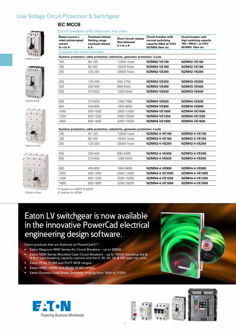
Circuit breakers with electronic trip units
Rated current = rated uninterrupted current In = Iu A
Overload release Setting range overload release Ir A
Short circuit release Non-Delayed Ii = In x A
Circuit breaker with normal switching capacity 50kA at 415V 50/60Hz Item no.
Circuit breaker with high switching capacity 150/85kA at 415V 50/60Hz Item no.
Supplied with screw terminals
Systems protection, cable protection, selectivity, generator protection, 3 pole
100 50-100 1200A fixed NZMN2-VE100 NZMH2-VE100
160 80-160 1920A fixed NZMN2-VE160 NZMH2-VE160
250 125-250 3000A fixed NZMN2-VE250 NZMH2-VE250
250 125-250 500-2750 NZMN3-VE250 NZMH3-VE250
400 200-400 800-4400 NZMN3-VE400 NZMH3-VE400
630 315-630 1260-5040 NZMN3-VE630 NZMH3-VE630
630 315-630 1260-7560 NZMN4-VE630 NZMH4-VE630
800 400-800 1600-9600 NZMN4-VE800 NZMH4-VE800
1000 500-1000 2000-12000 NZMN4-VE1000 NZMH4-VE1000
1250 630-1250 2500-15000 NZMN4-VE1250 NZMH4-VE1250
1600 800-1600 3200-19200 NZMN4-VE1600 NZMH4-VE1600
Systems protection, cable protection, selectivity, generator protection, 4 pole
100 50-100 1200A fixed NZMN2-4-VE100 NZMH2-4-VE100
160 80-160 1920A fixed NZMN2-4-VE160 NZMH2-4-VE160
250 125-250 3000A fixed NZMN2-4-VE250 NZMH2-4-VE250
400 200-400 800-4400 NZMN3-4-VE400 NZMH3-4-VE400
630 315-630 1260-5040 NZMN3-4-VE630 NZMH3-4-VE630
800 400-800 1600-9600 NZMN4-4-VE800 NZMH4-4-VE800
1000 500-1000 2000-12000 NZMN4-4-VE1000 NZMH4-4-VE1000
1250 630-1250 2500-15000 NZMN4-4-VE1250 NZMH4-4-VE1250
1600 800-1600 3200-19200 NZMN4-4-VE1600 NZMH4-4-VE1600
Applies for NZM2 & NZM3 Applies for NZM4
NZMN3-VE250
05/08/2015 259124 - HPL-ED2015 V12.0 EN 1 / 10
Circuit-breaker,�3p,�250A
Part�no. NZMN2-VE250Article�no. 259124
Similar to illustration
Delivery�programmeProduct range Circuit-breaker
Protective function Systems, cable, selectivity and generator protection
Standard/Approval IEC
Installation type Fixed
Release system Electronic release
Construction size NZM2
Description R.m.s. value measurement and “thermal memory”adjustable time delay setting to overcome current peaks tr: 2 – 20 s at 6 x Ir alsoinfinity (without overload releases)Adjustable delay time tsd: Steps: 0, 20, 60, 100, 200, 300, 500, 750, 1000 msi2t constant function: fixed OFF
Number of poles 3 pole
Standard equipment Screw connection
Switching�capacity
400/415 V 50/60 Hz Icu kA 50
Rated�current�=�rated�uninterrupted�current
Rated current = rated uninterrupted current In = Iu A 250
Setting�range
Overload trip
Ir A 125 - 250
Short-circuit releases
Non-delayed Ii = In x … 3000 A fixed
Delayed Isd = Ir x … 2 - 10
Technical�dataGeneralStandards IEC/EN 60947
Protection against direct contact Finger and back of hand proof to VDE 0106 Part 100
Climatic proofing Damp heat, constant, to IEC 60068-2-78Damp heat, cyclic, to IEC 60068-2-30
Ambient temperature °C
Ambient temperature, storage °C - 40 - + 80
Operation °C -25 - +70
Mechanical shock resistance (10 ms half-sinusoidal shock) according to IEC60068-2-27
g 20 (half-sinusoidal shock 20 ms)
Safe isolation to EN 61140
Between auxiliary contacts and main contacts V AC 500
between the auxiliary contacts V AC 300
Weight kg 2.345
NZMN2-VE160
05/07/2015 265772 - HPL-ED2015 V12.0 EN 1 / 8
Circuit-breaker,�3p,�1600A
Part�no. NZMN4-VE1600Article�no. 265772
Similar to illustration
Delivery�programmeProduct range Circuit-breaker
Protective function Systems, cable, selectivity and generator protection
Standard/Approval IEC
Installation type Fixed
Release system Electronic release
Construction size NZM4
Description R.m.s. value measurement and “thermal memory”adjustable time delay setting to overcome current peaks tr: 2 – 20 s at 6 x Ir alsoinfinity (without overload releases)Adjustable delay time tsd: Steps: 0, 20, 60, 100, 200, 300, 500, 750, 1000 msi2t constant function: switchable
Number of poles 3 pole
Standard equipment Screw connection
Switching�capacity
400/415 V 50/60 Hz Icu kA 50
Rated�current�=�rated�uninterrupted�current
Rated current = rated uninterrupted current In = Iu A 1600
Setting�range
Overload trip
Ir A 800 - 1600
Short-circuit releases
Non-delayed Ii = In x … 2 - 12
Delayed Isd = Ir x … 2 - 10
Technical�dataGeneralStandards IEC/EN 60947
Protection against direct contact Finger and back of hand proof to VDE 0106 Part 100
Climatic proofing Damp heat, constant, to IEC 60068-2-78Damp heat, cyclic, to IEC 60068-2-30
Ambient temperature °C
Ambient temperature, storage °C - 40 - + 80
Operation °C -25 - +70
Mechanical shock resistance (10 ms half-sinusoidal shock) according to IEC60068-2-27
g 15 (half-sinusoidal shock 11 ms)
Safe isolation to EN 61140
Between auxiliary contacts and main contacts V AC 500
between the auxiliary contacts V AC 300
NZMH4-VE1250
06/01/2017 265975 - HPL-ED2017 V32.0 EN 1 / 8
Circuit-breaker,�4p,�800A
Part�no. NZMN4-4-VE800Article�no. 265975
Delivery�programProduct range Circuit-breaker
Protective function Systems, cable, selectivity and generator protection
Standard/Approval IEC
Installation type Fixed
Release system Electronic release
Construction size NZM4
Description R.m.s. value measurement and “thermal memory”adjustable time delay setting to overcome current peaks tr: 2 – 20 s at 6 x Ir alsoinfinity (without overload releases)Adjustable delay time tsd: Steps: 0, 20, 60, 100, 200, 300, 500, 750, 1000 msi2t constant function: switchableSet value in neutral conductor is synchronous with set value Ir of main pole.
Number of poles 4 pole
Standard equipment Screw connection
Switching�capacity
400/415 V 50 Hz Icu kA 50
Rated�current�=�rated�uninterrupted�current
Rated current = rated uninterrupted current In = Iu A 800
Neutral conductor % of phaseconductor
CSA 100
Setting�range
Overload trip
Ir A 400 - 800
Main pole Ir A 400 - 800
Short-circuit releases
Non-delayed Ii = In x … 2 - 12
Delayed Isd = Ir x … 2 - 10
Technical�dataGeneralStandards IEC/EN 60947
Protection against direct contact Finger and back of hand proof to VDE 0106 Part 100
Climatic proofing Damp heat, constant, to IEC 60068-2-78Damp heat, cyclic, to IEC 60068-2-30
Ambient temperature
Ambient temperature, storage °C - 40 - + 70
Operation °C -25 - +70
Mechanical shock resistance (10 ms half-sinusoidal shock) according to IEC60068-2-27
g 15 (half-sinusoidal shock 11 ms)
Safe isolation to EN 61140
Between auxiliary contacts and main contacts V AC 500
NZMN4-4-VE800
Eaton LV switchgear is now available in the innovative PowerCad electrical engineering design software.Eaton products that are featured on PowerCad-5™:
• Eaton Magnum MWI Series Air Circuit Breakers – up to 6300A.
• Eaton NZM Series Moulded Case Circuit Breakers – up to 1600A including the B, N & H type breaking capacity options and the A, M, AE, VE & ME type trip units.
• Eaton PLS6, PLSM and PLHT MCB ranges.
• Eaton eRB6, eRBM and PKNM RCBO ranges.
• Eaton Dumeco Load Break Switches ranging from 160A to 3150A
87Power Distribution product guide eatoncorp.com.au December 2017
IEC MCCB
Low Voltage Circuit Protection & Switchgear
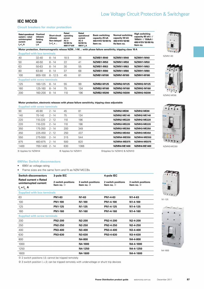
Rated operational current = rated uninterrupted currentIn= Iu A
Overload releasesSetting rangeIr A
Short-circuit releasesNon-delayedIi = In x ...
Rated operating powerAC-3 50/60 Hz400 V P kW
Rated operational currentAC-3 50/60 Hz400 V Ie A
Basic switching capacity 25 kA400/415V 50/60 Hz Item no.
Normal switching capacity 50 kA400/415V 50/60 Hz Item no.
High switching capacity 85 kA / 100kA / 150kA400/415V 50/60 Hz Item no.
Motor protection, thermomagnetic release NZM...1-M...: with phase failure sensitivity, tripping class 10 A
Supplied with box terminals
40 32-40 8 - 14 18.5 36 NZMB1-M40 NZMN1-M40 NZMH1-M40
50 40-50 8 - 14 22 41 NZMB1-M50 NZMN1-M50 NZMH1-M50
63 50-63 8 - 14 30 55 NZMB1-M63 NZMN1-M63 NZMH1-M63
80 63-80 8 - 14 37 68 NZMB1-M80 NZMN1-M80 NZMH1-M80
100 800-100 8 - 12.5 45 81 NZMB1-M100 NZMN1-M100 NZMH1-M100
Supplied with screw terminals
125 100-125 8 - 14 55 99 NZMB2-M125 NZMN2-M125 NZMH2-M125
160 125-160 8 - 14 75 134 NZMB2-M160 NZMN2-M160 NZMH2-M160
200 160-200 8 - 14 110 196 NZMB2-M200 NZMN2-M200 NZMH2-M200
Motor protection, electronic releases with phase failure sensitivity, tripping class adjustable
Supplied with screw terminals
90 45-90 2 - 14 45 81 NZMN2-ME90 NZMH2-ME90
140 70-140 2 - 14 75 134 NZMN2-ME140 NZMH2-ME140
220 110-220 2 - 12 110 196 NZMN2-ME220 NZMH2-ME220
220 110-220 2 - 14 110 196 NZMN3-ME220 NZMH3-ME220
350 175-350 2 - 14 200 349 NZMN3-ME350 NZMH3-ME350
450 225-450 2 - 12 250 437 NZMN3-ME450 NZMH3-ME450
550 275-550 2 - 14 315 544 NZMN4-ME550 NZMH4-ME550
875 483-875 2 - 14 500 820 NZMN4-ME875 NZMH4-ME875
1400 700-1400 2 - 14 630 1066 NZMN4-ME1400 NZMH4-ME1400
690Vac Switch disconnectors
Switch-disconnectors 3-pole IEC 4-pole IEC
Rated current = Rated uninterrupted current
In = Iu, A
2 switch positions Item no.
3 switch positions Item no.
2 switch positions Item no.
3 switch positions Item no.
Supplied with box terminals
63 PN1-63 N1-63 PN1-4-63 N1-4-63
100 PN1-100 N1-100 PN1-4-100 N1-4-100
125 PN1-125 N1-125 PN1-4-125 N1-4-125
160 PN1-160 N1-160 PN1-4-160 N1-4-160
Supplied with screw terminals
200 PN2-200 N2-200 PN2-4-200 N2-4-200
250 PN2-250 N2-250 PN2-4-250 N2-4-250
400 PN3-400 N3-400 PN3-4-400 N3-4-400
630 PN3-630 N3-630 PN3-4-630 N3-4-630
800 N4-800 N4-4-800
1000 N4-1000 N4-4-1000
1250 N4-1250 N4-4-1250
1600 N4-1600 N4-4-1600
2 switch positions I,0; cannot be tripped remotely
3 switch position I,+,0; can be tripped remotely with undervoltage or shunt trip devices
N1-125
N4-1600
• 690V ac voltage rating
• Frame sizes are the same form and fit as NZM MCCBs
Circuit breakers for motor protection
NZMN1-63
NZMN2-ME90
NZMN3-ME350
Applies for NZMH4 Applies for NZMH1 Applies for NZMH2 & NZMH3
88 Power Distribution product guide eatoncorp.com.au December 2017
IEC MCCB
Low Voltage Circuit Protection & Switchgear
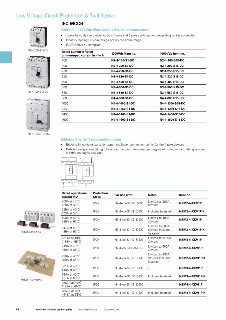
Bridging Kits for 1 pole configuration
Rated operational current In A
Protection Class
For use with Notes Item no.
200A at 40°C 160A at 65°C IP2X N2-4-xxx-S1 (S15)-DC Limited to 200A
devices NZM2-4-XKV1P
225A at 40°C 170A at 65°C IP2X N2-4-xxx-S1 (S15)-DC Includes heatsink NZM2-4-XKV1P-K
400A at 40°C 388A at 65°C IP2X N3-4-xxx-S1 (S15)-DC Limited to 400A
devices NZM3-4-XKV1P
517A at 40°C 435A at 65°C IP2X N3-4-xxx-S1 (S15)-DC
Limited to 500A devices Includes heatsink
NZM3-4-XKV1P-K
1274A at 40°C 1138A at 65°C IP2X N4-4-xxx-S1 (S15)-DC Limited to 1250A
devices NZM4-4-XKV1P
213A at 40°C 160A at 65°C IP00 N2-4-xxx-S1 (S15)-DC Limited to 200A
devices NZM2-4-XKVI1P
238A at 40°C 180A at 65°C IP00 N2-4-xxx-S1 (S15)-DC
Limited to 250A devices Includes heatsink
NZM2-4-XKVI1P-K
501A at 40°C 418A at 65°C IP00 N3-4-xxx-S1 (S15)-DC - NZM3-4-XKVI1P
534A at 40°C 451A at 65°C IP00 N3-4-xxx-S1 (S15)-DC Includes heatsink NZM3-4-XKVI1P-K
1260A at 40°C 1138A at 65°C IP00 N4-4-xxx-S1 (S15)-DC - NZM4-4-XKVI1P
1552A at 40°C 1448A at 65°C IP00 N4-4-xxx-S1 (S15)-DC Includes heatsink NZM4-4-XKVI1P-K
• Bridging kit contains parts for upper and lower connection points for the 4 pole devices
• Detailed assignment taking into account ambient temperature, degree of protection and fitting position is listed on pages 434-435
1000Vdc / 1500Vdc Photovoltaic Switch disconnectors
Rated current = Rated uninterruped current In = Iu A
1000Vdc Item no. 1500Vdc Item no.
160 N2-4-160-S1-DC N2-4-160-S15-DC
200 N2-4-200-S1-DC N2-4-200-S15-DC
250 N2-4-250-S1-DC N2-4-250-S15-DC
320 N3-4-320-S1-DC N3-4-320-S15-DC
400 N3-4-400-S1-DC N3-4-400-S15-DC
500 N3-4-500-S1-DC N3-4-500-S15-DC
550 N3-4-550-S1-DC N3-4-550-S15-DC
800 N4-4-800-S1-DC N4-4-800-S15-DC
1000 N4-4-1000-S1-DC N4-4-1000-S15-DC
1250 N4-4-1250-S1-DC N4-4-1250-S15-DC
1400 N4-4-1400-S1-DC N4-4-1400-S15-DC
1600 N4-4-1600-S1-DC N4-4-1600-S15-DC
• 4-pole basic device usable for both 1-pole and 2-pole configuration depending on the connection
• Industry leading DC22-A ratings across the entire range
• IEC/EN 60947-3 compliant
Link set, +insulating plates, 4p, /1p
Part no. NZM4-4-XKVI1PCatalog No. 180019
Delivery programNumber of poles 1 pole
Accessories DC link kit
Number of conductors 4
Jumper kit with insulating plates, phase isolators IP00 and heat sinks
Rated current In A 1260 (40 °C,)1138 (65 °C)
For use with N4-4-(800)(1000)(1250)(1400)-S1(-S15)-DCN4-4-...-S1(-S15)-PV-NA
Notes
Model contains parts for upper switch side for 4 pole switches N...-DC that are used as 1 pole switches for DC.
The links each connect contacts in series.
Incoming unit and outgoer at bottom or top, user-definable.
See figure connection type.
Design verification as per IEC/EN 61439IEC/EN 61439 design verification
10.2 Strength of materials and parts
10.2.2 Corrosion resistance Meets the product standard's requirements.
10.2.3.1 Verification of thermal stability of enclosures Meets the product standard's requirements.
10.2.3.2 Verification of resistance of insulating materials to normal heat Meets the product standard's requirements.
10.2.3.3 Verification of resistance of insulating materials to abnormal heatand fire due to internal electric effects
Meets the product standard's requirements.
10.2.4 Resistance to ultra-violet (UV) radiation Meets the product standard's requirements.
10.2.5 Lifting Does not apply, since the entire switchgear needs to be evaluated.
10.2.6 Mechanical impact Does not apply, since the entire switchgear needs to be evaluated.
10.2.7 Inscriptions Meets the product standard's requirements.
10.3 Degree of protection of ASSEMBLIES Does not apply, since the entire switchgear needs to be evaluated.
10.4 Clearances and creepage distances Meets the product standard's requirements.
10.5 Protection against electric shock Does not apply, since the entire switchgear needs to be evaluated.
10.6 Incorporation of switching devices and components Does not apply, since the entire switchgear needs to be evaluated.
10.7 Internal electrical circuits and connections Is the panel builder's responsibility.
10.8 Connections for external conductors Is the panel builder's responsibility.
10.9 Insulation properties
10.9.2 Power-frequency electric strength Is the panel builder's responsibility.
10.9.3 Impulse withstand voltage Is the panel builder's responsibility.
10.9.4 Testing of enclosures made of insulating material Is the panel builder's responsibility.
10.10 Temperature rise The panel builder is responsible for the temperature rise calculation. Eaton willprovide heat dissipation data for the devices.
10.11 Short-circuit rating Is the panel builder's responsibility. The specifications for the switchgear must beobserved.
10.12 Electromagnetic compatibility Is the panel builder's responsibility. The specifications for the switchgear must beobserved.
10.13 Mechanical function The device meets the requirements, provided the information in the instructionleaflet (IL) is observed.
Technical data ETIM 6.0Low-voltage industrial components (EG000017) / Wiring set for power circuit breaker (EC002050)
Electric engineering, automation, process control engineering / Low-voltage switch technology / Circuit breaker (LV < 1 kV) / Wiring set for circuit breaker ([email protected] [ACN957008])
Suitable for number of poles 1
Model -
11/23/2017 180019 - HPL-ED2017 V38.0 EN 1 / 2
NZM4-4-XKVI1P-K
35
Photovoltaic - Switch-disconnectors up to 1500 V
Switch-disconnectors for 1000/1500 V DC, 1 and 2 pole• IEC/EN 60947-3
• CCC China Compulsory Certificate
• Main switch characteristics including positive drive to IEC/EN 60204 and VDE 0113
• Isolating characteristics to IEC/EN 60947 and VDE 0660
• Busbar tag shroud to VDE0160 Part100
• Switch-disconnectors N can, in addition, be combined with voltage releases NZM...-XU, NZM...-XA
and auxiliary contacts as well as with remote operator NZM...-XR...
• For DC switching you will need the series connection of all 4 current paths.
See picture of accessories for jumper kits
• Standard equipment: Screw-type connection, frame terminal available as an option
• In ungrounded networks (e.g. IT) the installation has to be done in a way to keep the likelihood of a
double-ground fault neglectably low.
• Switches can not be combined with withdrawable units and/or connection on rear
• For N4-4 -...- S15-DC, feed only from below in connection with NZM4-4-XKV(I)2P(-K).
Rated operational Short-circuit Screw 1000VDC 1500VDC Units per
current rated = protective connection Fixed mounted Fixed mounted package
uninterrupted device fuse Designation Designation
current gR-characteristic Article No. Article No.
In = IuA A
160 200 S N2-4-160-S1-DC N2-4-160-S15-DC 1 pcs.
127732 167688
200 200 S N2-4-200-S1-DC N2-4-200-S15-DC 1 pcs.
127733 167689
250 200 S N2-4-250-S1-DC N2-4-250-S15-DC 1 pcs.
154940 167690
320 500 S N3-4-320-S1-DC N3-4-320-S15-DC 1 pcs.
127734 166407
400 500 S N3-4-400-S1-DC N3-4-400-S15-DC 1 pcs.
142267 166408
500 500 S N3-4-500-S1-DC N3-4-500-S15-DC 1 pcs.
142268 166409
550 500 S N3-4-550-S1-DC N3-4-550-S15-DC 1 pcs.
168567 168568
800 - S N4-4-800-S1-DC N4-4-800-S15-DC 1 pcs.
119890 166413
1000 - S N4-4-1000-S1-DC N4-4-1000-S15-DC 1 pcs.
119891 166414
1250 - S N4-4-1250-S1-DC N4-4-1250-S15-DC 1 pcs.
119886 166415
1400 - S N4-4-1400-S1-DC N4-4-1400-S15-DC 1 pcs.
119887 166416
1600 - S N4-4-1600-S1-DC N4-4-1600-S15-DC 1 pcs.
152552 166417
EATON CORPORATION BR1601001Z-EN
N2-4-200-S15-DC
NZM2-4-XKV1P-K
04/07/2016 168592 - HPL-ED2016 V20.0 EN 1 / 2
Link�kit,�+cover,�+heat�sink,�4p,�/1p
Part�no. NZM2-4-XKV1P-KArticle�no. 168592Catalog�No. NZM2-4-XKV1P-K
Delivery�programmeNumber of poles 1 pole
Accessories DC link kit
Number of conductors 4
Jumper kit with cover IP2X and heat sink
Rated current In A 225 (40 °C,)170 (65 °C)
For use with N2-4-…-S1(-S15)-DC
Notes
Model contains parts for upper switch side for 4 pole switches N...-DC that are used as 1 pole switches for DC.
The links each connect contacts in series.
Incoming unit and outgoer at bottom or top, user-definable.
See figure connection type.
Design�verification�as�per�IEC/EN�61439IEC/EN 61439 design verification
10.2 Strength of materials and parts
10.2.2 Corrosion resistance Meets the product standard's requirements.
10.2.3.1 Verification of thermal stability of enclosures Meets the product standard's requirements.
10.2.3.2 Verification of resistance of insulating materials to normal heat Meets the product standard's requirements.
10.2.3.3 Verification of resistance of insulating materials to abnormal heatand fire due to internal electric effects
Meets the product standard's requirements.
10.2.4 Resistance to ultra-violet (UV) radiation Meets the product standard's requirements.
10.2.5 Lifting Does not apply, since the entire switchgear needs to be evaluated.
10.2.6 Mechanical impact Does not apply, since the entire switchgear needs to be evaluated.
10.2.7 Inscriptions Meets the product standard's requirements.
10.3 Degree of protection of ASSEMBLIES Does not apply, since the entire switchgear needs to be evaluated.
10.4 Clearances and creepage distances Meets the product standard's requirements.
10.5 Protection against electric shock Does not apply, since the entire switchgear needs to be evaluated.
10.6 Incorporation of switching devices and components Does not apply, since the entire switchgear needs to be evaluated.
10.7 Internal electrical circuits and connections Is the panel builder's responsibility.
10.8 Connections for external conductors Is the panel builder's responsibility.
10.9 Insulation properties
10.9.2 Power-frequency electric strength Is the panel builder's responsibility.
10.9.3 Impulse withstand voltage Is the panel builder's responsibility.
10.9.4 Testing of enclosures made of insulating material Is the panel builder's responsibility.
10.10 Temperature rise The panel builder is responsible for the temperature rise calculation. Eaton willprovide heat dissipation data for the devices.
10.11 Short-circuit rating Is the panel builder's responsibility. The specifications for the switchgear must beobserved.
10.12 Electromagnetic compatibility Is the panel builder's responsibility. The specifications for the switchgear must beobserved.
10.13 Mechanical function The device meets the requirements, provided the information in the instructionleaflet (IL) is observed.
Technical�data�ETIM�6.0Low-voltage industrial components (EG000017) / Wiring set for power circuit breaker (EC002050)
Electric engineering, automation, process control engineering / Low-voltage switch technology / Circuit breaker (LV < 1 kV) / Wiring set for circuit breaker ([email protected] [ACN957008])
Suitable for number of poles 4
Model -
03/11/2016 167689 - HPL-ED2016 V20.0 EN 1 / 5
Switch-disconnector�4p�200A�1500VDC
Part�no. N2-4-200-S15-DCArticle�no. 167689Catalog�No. N2-4-200-S15-DC
Similar to illustration
Delivery�programmeProduct range Switch-disconnectors
Protective function Disconnectors/main switchesPhotovoltaic applications
Product range DC switch-disconnectors
Application field Utility buildingsOpen areas
Part no. N...DC
Standard/Approval IEC
Installation type Fixed
Construction size N2
Description IEC/EN 60947-3CCC China Compulsory CertificateMain switch characteristics including positive drive to IEC/EN 60204 and VDE 0113.Isolating characteristics to IEC/EN 60947-3 and VDE 0660.N switch-disconnectors can, in addition, be combined with NZM...-XU, NZM...-XAshunt releases and auxiliary contacts as well as with NZM...-XR... remote operator.For DC switching, all 4 contacts must be connected in series. Refer to theinformation on jumper kit accessories.Supplied as standard: Screw connection; box terminal optional.When working with ungrounded systems (e.g., IT), the installation must ensure thata double ground fault will be impossible.Switch can not be combined with plug-in/withdrawable units and/or connection onrear.
Connection options
Number of poles 4-pole basic device, usable in a 1-pole or 2-pole configuration depending on thetype of connection
Standard equipment Screw connection
Switch positions I, +, 0
Rated current = rated uninterrupted current In = Iu A 200
Remotely control / trip Remote operation with shunt releases / remote operator
Rated operating frequency DC
35
Photovoltaic - Switch-disconnectors up to 1500 V
Switch-disconnectors for 1000/1500 V DC, 1 and 2 pole• IEC/EN 60947-3
• CCC China Compulsory Certificate
• Main switch characteristics including positive drive to IEC/EN 60204 and VDE 0113
• Isolating characteristics to IEC/EN 60947 and VDE 0660
• Busbar tag shroud to VDE0160 Part100
• Switch-disconnectors N can, in addition, be combined with voltage releases NZM...-XU, NZM...-XA
and auxiliary contacts as well as with remote operator NZM...-XR...
• For DC switching you will need the series connection of all 4 current paths.
See picture of accessories for jumper kits
• Standard equipment: Screw-type connection, frame terminal available as an option
• In ungrounded networks (e.g. IT) the installation has to be done in a way to keep the likelihood of a
double-ground fault neglectably low.
• Switches can not be combined with withdrawable units and/or connection on rear
• For N4-4 -...- S15-DC, feed only from below in connection with NZM4-4-XKV(I)2P(-K).
Rated operational Short-circuit Screw 1000VDC 1500VDC Units per
current rated = protective connection Fixed mounted Fixed mounted package
uninterrupted device fuse Designation Designation
current gR-characteristic Article No. Article No.
In = IuA A
160 200 S N2-4-160-S1-DC N2-4-160-S15-DC 1 pcs.
127732 167688
200 200 S N2-4-200-S1-DC N2-4-200-S15-DC 1 pcs.
127733 167689
250 200 S N2-4-250-S1-DC N2-4-250-S15-DC 1 pcs.
154940 167690
320 500 S N3-4-320-S1-DC N3-4-320-S15-DC 1 pcs.
127734 166407
400 500 S N3-4-400-S1-DC N3-4-400-S15-DC 1 pcs.
142267 166408
500 500 S N3-4-500-S1-DC N3-4-500-S15-DC 1 pcs.
142268 166409
550 500 S N3-4-550-S1-DC N3-4-550-S15-DC 1 pcs.
168567 168568
800 - S N4-4-800-S1-DC N4-4-800-S15-DC 1 pcs.
119890 166413
1000 - S N4-4-1000-S1-DC N4-4-1000-S15-DC 1 pcs.
119891 166414
1250 - S N4-4-1250-S1-DC N4-4-1250-S15-DC 1 pcs.
119886 166415
1400 - S N4-4-1400-S1-DC N4-4-1400-S15-DC 1 pcs.
119887 166416
1600 - S N4-4-1600-S1-DC N4-4-1600-S15-DC 1 pcs.
152552 166417
EATON CORPORATION BR1601001Z-EN
N3-4-400-S15-DC
35
Photovoltaic - Switch-disconnectors up to 1500 V
Switch-disconnectors for 1000/1500 V DC, 1 and 2 pole• IEC/EN 60947-3
• CCC China Compulsory Certificate
• Main switch characteristics including positive drive to IEC/EN 60204 and VDE 0113
• Isolating characteristics to IEC/EN 60947 and VDE 0660
• Busbar tag shroud to VDE0160 Part100
• Switch-disconnectors N can, in addition, be combined with voltage releases NZM...-XU, NZM...-XA
and auxiliary contacts as well as with remote operator NZM...-XR...
• For DC switching you will need the series connection of all 4 current paths.
See picture of accessories for jumper kits
• Standard equipment: Screw-type connection, frame terminal available as an option
• In ungrounded networks (e.g. IT) the installation has to be done in a way to keep the likelihood of a
double-ground fault neglectably low.
• Switches can not be combined with withdrawable units and/or connection on rear
• For N4-4 -...- S15-DC, feed only from below in connection with NZM4-4-XKV(I)2P(-K).
Rated operational Short-circuit Screw 1000VDC 1500VDC Units per
current rated = protective connection Fixed mounted Fixed mounted package
uninterrupted device fuse Designation Designation
current gR-characteristic Article No. Article No.
In = IuA A
160 200 S N2-4-160-S1-DC N2-4-160-S15-DC 1 pcs.
127732 167688
200 200 S N2-4-200-S1-DC N2-4-200-S15-DC 1 pcs.
127733 167689
250 200 S N2-4-250-S1-DC N2-4-250-S15-DC 1 pcs.
154940 167690
320 500 S N3-4-320-S1-DC N3-4-320-S15-DC 1 pcs.
127734 166407
400 500 S N3-4-400-S1-DC N3-4-400-S15-DC 1 pcs.
142267 166408
500 500 S N3-4-500-S1-DC N3-4-500-S15-DC 1 pcs.
142268 166409
550 500 S N3-4-550-S1-DC N3-4-550-S15-DC 1 pcs.
168567 168568
800 - S N4-4-800-S1-DC N4-4-800-S15-DC 1 pcs.
119890 166413
1000 - S N4-4-1000-S1-DC N4-4-1000-S15-DC 1 pcs.
119891 166414
1250 - S N4-4-1250-S1-DC N4-4-1250-S15-DC 1 pcs.
119886 166415
1400 - S N4-4-1400-S1-DC N4-4-1400-S15-DC 1 pcs.
119887 166416
1600 - S N4-4-1600-S1-DC N4-4-1600-S15-DC 1 pcs.
152552 166417
EATON CORPORATION BR1601001Z-EN
N4-4-1250-S15-DC
89Power Distribution product guide eatoncorp.com.au December 2017
IEC MCCB
Low Voltage Circuit Protection & Switchgear
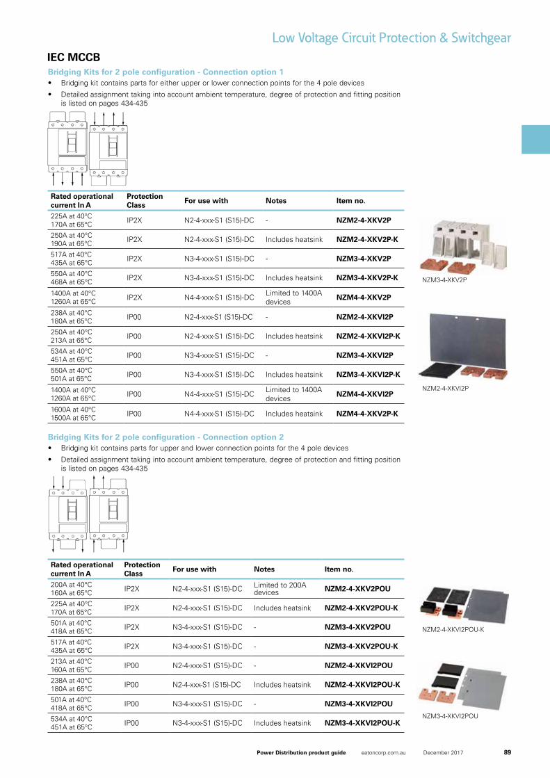
Bridging Kits for 2 pole configuration - Connection option 1
Bridging Kits for 2 pole configuration - Connection option 2
Rated operational current In A
Protection Class
For use with Notes Item no.
225A at 40°C 170A at 65°C IP2X N2-4-xxx-S1 (S15)-DC - NZM2-4-XKV2P
250A at 40°C 190A at 65°C IP2X N2-4-xxx-S1 (S15)-DC Includes heatsink NZM2-4-XKV2P-K
517A at 40°C 435A at 65°C IP2X N3-4-xxx-S1 (S15)-DC - NZM3-4-XKV2P
550A at 40°C 468A at 65°C IP2X N3-4-xxx-S1 (S15)-DC Includes heatsink NZM3-4-XKV2P-K
1400A at 40°C 1260A at 65°C IP2X N4-4-xxx-S1 (S15)-DC Limited to 1400A
devices NZM4-4-XKV2P
238A at 40°C 180A at 65°C IP00 N2-4-xxx-S1 (S15)-DC - NZM2-4-XKVI2P
250A at 40°C 213A at 65°C IP00 N2-4-xxx-S1 (S15)-DC Includes heatsink NZM2-4-XKVI2P-K
534A at 40°C 451A at 65°C IP00 N3-4-xxx-S1 (S15)-DC - NZM3-4-XKVI2P
550A at 40°C 501A at 65°C IP00 N3-4-xxx-S1 (S15)-DC Includes heatsink NZM3-4-XKVI2P-K
1400A at 40°C 1260A at 65°C IP00 N4-4-xxx-S1 (S15)-DC Limited to 1400A
devices NZM4-4-XKVI2P
1600A at 40°C 1500A at 65°C IP00 N4-4-xxx-S1 (S15)-DC Includes heatsink NZM4-4-XKV2P-K
Rated operational current In A
Protection Class
For use with Notes Item no.
200A at 40°C 160A at 65°C IP2X N2-4-xxx-S1 (S15)-DC Limited to 200A
devices NZM2-4-XKV2POU
225A at 40°C 170A at 65°C IP2X N2-4-xxx-S1 (S15)-DC Includes heatsink NZM2-4-XKV2POU-K
501A at 40°C 418A at 65°C IP2X N3-4-xxx-S1 (S15)-DC - NZM3-4-XKV2POU
517A at 40°C 435A at 65°C IP2X N3-4-xxx-S1 (S15)-DC - NZM3-4-XKV2POU-K
213A at 40°C 160A at 65°C IP00 N2-4-xxx-S1 (S15)-DC - NZM2-4-XKVI2POU
238A at 40°C 180A at 65°C IP00 N2-4-xxx-S1 (S15)-DC Includes heatsink NZM2-4-XKVI2POU-K
501A at 40°C 418A at 65°C IP00 N3-4-xxx-S1 (S15)-DC - NZM3-4-XKVI2POU
534A at 40°C 451A at 65°C IP00 N3-4-xxx-S1 (S15)-DC Includes heatsink NZM3-4-XKVI2POU-K
• Bridging kit contains parts for either upper or lower connection points for the 4 pole devices
• Detailed assignment taking into account ambient temperature, degree of protection and fitting position is listed on pages 434-435
• Bridging kit contains parts for upper and lower connection points for the 4 pole devices
• Detailed assignment taking into account ambient temperature, degree of protection and fitting position is listed on pages 434-435
Link kit, +insulating plates, 4p, /2p
Part no. NZM2-4-XKVI2PCatalog No. 168586Eaton Catalog No. NZM2-4-XKVI2P
Delivery programNumber of poles 2 pole
Accessories DC link kit
Number of conductors 4
Jumper kit with insulating plates/phase isolator IP00
Rated current In A 238 (40 °C,)180 (65 °C)
For use with N2-4-…-S1(-S15)-DC
Notes
Model contains parts for upper switch side for 4 pole switches N...-DC that are used as 2 pole switches for DC.
The links each connect contacts in series.
Incoming unit and outgoer at bottom or top, user-definable.
See figure connection type.
Design verification as per IEC/EN 61439IEC/EN 61439 design verification
10.2 Strength of materials and parts
10.2.2 Corrosion resistance Meets the product standard's requirements.
10.2.3.1 Verification of thermal stability of enclosures Meets the product standard's requirements.
10.2.3.2 Verification of resistance of insulating materials to normal heat Meets the product standard's requirements.
10.2.3.3 Verification of resistance of insulating materials to abnormal heatand fire due to internal electric effects
Meets the product standard's requirements.
10.2.4 Resistance to ultra-violet (UV) radiation Meets the product standard's requirements.
10.2.5 Lifting Does not apply, since the entire switchgear needs to be evaluated.
10.2.6 Mechanical impact Does not apply, since the entire switchgear needs to be evaluated.
10.2.7 Inscriptions Meets the product standard's requirements.
10.3 Degree of protection of ASSEMBLIES Does not apply, since the entire switchgear needs to be evaluated.
10.4 Clearances and creepage distances Meets the product standard's requirements.
10.5 Protection against electric shock Does not apply, since the entire switchgear needs to be evaluated.
10.6 Incorporation of switching devices and components Does not apply, since the entire switchgear needs to be evaluated.
10.7 Internal electrical circuits and connections Is the panel builder's responsibility.
10.8 Connections for external conductors Is the panel builder's responsibility.
10.9 Insulation properties
10.9.2 Power-frequency electric strength Is the panel builder's responsibility.
10.9.3 Impulse withstand voltage Is the panel builder's responsibility.
10.9.4 Testing of enclosures made of insulating material Is the panel builder's responsibility.
10.10 Temperature rise The panel builder is responsible for the temperature rise calculation. Eaton willprovide heat dissipation data for the devices.
10.11 Short-circuit rating Is the panel builder's responsibility. The specifications for the switchgear must beobserved.
10.12 Electromagnetic compatibility Is the panel builder's responsibility. The specifications for the switchgear must beobserved.
10.13 Mechanical function The device meets the requirements, provided the information in the instructionleaflet (IL) is observed.
Technical data ETIM 6.0Low-voltage industrial components (EG000017) / Wiring set for power circuit breaker (EC002050)
Electric engineering, automation, process control engineering / Low-voltage switch technology / Circuit breaker (LV < 1 kV) / Wiring set for circuit breaker ([email protected] [ACN957008])
Suitable for number of poles 4
Model -
11/24/2017 168586 - HPL-ED2017 V38.0 EN 1 / 2
NZM2-4-XKVI2P
NZM3-4-XKV2P
03/03/2017 131731 - HPL-ED2017 V30.0 EN 1 / 2
Terminal�jumper,�with�cover�4p/2p
Part�no. NZM3-4-XKV2PArticle�no. 131731
Delivery�programNumber of poles 2 pole
Accessories DC link kit
Number of conductors 4
Jumper kit with cover IP2X
Rated current In A 517 (40 °C,)435 (65 °C)
For use with N3-4-…-S1(-S15)-DC
Notes
Model contains parts for upper switch side for 4 pole switches N...-DC that are used as 2 pole switches for DC.
The links each connect contacts in series.
Incoming unit and outgoer at bottom or top, user-definable.
See figure connection type.
Design�verification�as�per�IEC/EN�61439IEC/EN 61439 design verification
10.2 Strength of materials and parts
10.2.2 Corrosion resistance Meets the product standard's requirements.
10.2.3.1 Verification of thermal stability of enclosures Meets the product standard's requirements.
10.2.3.2 Verification of resistance of insulating materials to normal heat Meets the product standard's requirements.
10.2.3.3 Verification of resistance of insulating materials to abnormal heatand fire due to internal electric effects
Meets the product standard's requirements.
10.2.4 Resistance to ultra-violet (UV) radiation Meets the product standard's requirements.
10.2.5 Lifting Does not apply, since the entire switchgear needs to be evaluated.
10.2.6 Mechanical impact Does not apply, since the entire switchgear needs to be evaluated.
10.2.7 Inscriptions Meets the product standard's requirements.
10.3 Degree of protection of ASSEMBLIES Does not apply, since the entire switchgear needs to be evaluated.
10.4 Clearances and creepage distances Meets the product standard's requirements.
10.5 Protection against electric shock Does not apply, since the entire switchgear needs to be evaluated.
10.6 Incorporation of switching devices and components Does not apply, since the entire switchgear needs to be evaluated.
10.7 Internal electrical circuits and connections Is the panel builder's responsibility.
10.8 Connections for external conductors Is the panel builder's responsibility.
10.9 Insulation properties
10.9.2 Power-frequency electric strength Is the panel builder's responsibility.
10.9.3 Impulse withstand voltage Is the panel builder's responsibility.
10.9.4 Testing of enclosures made of insulating material Is the panel builder's responsibility.
10.10 Temperature rise The panel builder is responsible for the temperature rise calculation. Eaton willprovide heat dissipation data for the devices.
10.11 Short-circuit rating Is the panel builder's responsibility. The specifications for the switchgear must beobserved.
10.12 Electromagnetic compatibility Is the panel builder's responsibility. The specifications for the switchgear must beobserved.
10.13 Mechanical function The device meets the requirements, provided the information in the instructionleaflet (IL) is observed.
Technical�data�ETIM�6.0Low-voltage industrial components (EG000017) / Wiring set for power circuit breaker (EC002050)
Electric engineering, automation, process control engineering / Low-voltage switch technology / Circuit breaker (LV < 1 kV) / Wiring set for circuit breaker ([email protected] [ACN957008])
Suitable for number of poles 4
Model -
03/11/2016 167689 - HPL-ED2016 V20.0 EN 1 / 5
Switch-disconnector�4p�200A�1500VDC
Part�no. N2-4-200-S15-DCArticle�no. 167689Catalog�No. N2-4-200-S15-DC
Similar to illustration
Delivery�programmeProduct range Switch-disconnectors
Protective function Disconnectors/main switchesPhotovoltaic applications
Product range DC switch-disconnectors
Application field Utility buildingsOpen areas
Part no. N...DC
Standard/Approval IEC
Installation type Fixed
Construction size N2
Description IEC/EN 60947-3CCC China Compulsory CertificateMain switch characteristics including positive drive to IEC/EN 60204 and VDE 0113.Isolating characteristics to IEC/EN 60947-3 and VDE 0660.N switch-disconnectors can, in addition, be combined with NZM...-XU, NZM...-XAshunt releases and auxiliary contacts as well as with NZM...-XR... remote operator.For DC switching, all 4 contacts must be connected in series. Refer to theinformation on jumper kit accessories.Supplied as standard: Screw connection; box terminal optional.When working with ungrounded systems (e.g., IT), the installation must ensure thata double ground fault will be impossible.Switch can not be combined with plug-in/withdrawable units and/or connection onrear.
Connection options
Number of poles 4-pole basic device, usable in a 1-pole or 2-pole configuration depending on thetype of connection
Standard equipment Screw connection
Switch positions I, +, 0
Rated current = rated uninterrupted current In = Iu A 200
Remotely control / trip Remote operation with shunt releases / remote operator
Rated operating frequency DC
03/11/2016 167689 - HPL-ED2016 V20.0 EN 1 / 5
Switch-disconnector�4p�200A�1500VDC
Part�no. N2-4-200-S15-DCArticle�no. 167689Catalog�No. N2-4-200-S15-DC
Similar to illustration
Delivery�programmeProduct range Switch-disconnectors
Protective function Disconnectors/main switchesPhotovoltaic applications
Product range DC switch-disconnectors
Application field Utility buildingsOpen areas
Part no. N...DC
Standard/Approval IEC
Installation type Fixed
Construction size N2
Description IEC/EN 60947-3CCC China Compulsory CertificateMain switch characteristics including positive drive to IEC/EN 60204 and VDE 0113.Isolating characteristics to IEC/EN 60947-3 and VDE 0660.N switch-disconnectors can, in addition, be combined with NZM...-XU, NZM...-XAshunt releases and auxiliary contacts as well as with NZM...-XR... remote operator.For DC switching, all 4 contacts must be connected in series. Refer to theinformation on jumper kit accessories.Supplied as standard: Screw connection; box terminal optional.When working with ungrounded systems (e.g., IT), the installation must ensure thata double ground fault will be impossible.Switch can not be combined with plug-in/withdrawable units and/or connection onrear.
Connection options
Number of poles 4-pole basic device, usable in a 1-pole or 2-pole configuration depending on thetype of connection
Standard equipment Screw connection
Switch positions I, +, 0
Rated current = rated uninterrupted current In = Iu A 200
Remotely control / trip Remote operation with shunt releases / remote operator
Rated operating frequency DC
NZM2-4-XKVI2POU-K
Jumper kit, +insulating plates, +heat sink, 4/2 p
Part no. NZM2-4-XKVI2POU-KCatalog No. 170119Eaton Catalog No. NZM2-4-XKVI2POU-K
Delivery programNumber of poles 2 pole
Accessories DC link kit
Number of conductors 4
Jumper kit with IP2X cover and heat sinkincoming unit/outgoer on two sides
Rated current In A 238 (40 °C,)180 (65 °C)
For use with N2-4-…-S1(-S15)-DC
Notes
Part no. includes parts for upper switch side for 4-pole N...-DC switches that are used as 2-pole switches for DC.
The links connect contacts in series. | Incoming unit and outgoer at bottom or top as desired.
Incoming unit and outgoer not on the same side.
See cicuit type diagram.
Design verification as per IEC/EN 61439IEC/EN 61439 design verification
10.2 Strength of materials and parts
10.2.2 Corrosion resistance Meets the product standard's requirements.
10.2.3.1 Verification of thermal stability of enclosures Meets the product standard's requirements.
10.2.3.2 Verification of resistance of insulating materials to normal heat Meets the product standard's requirements.
10.2.3.3 Verification of resistance of insulating materials to abnormal heatand fire due to internal electric effects
Meets the product standard's requirements.
10.2.4 Resistance to ultra-violet (UV) radiation Meets the product standard's requirements.
10.2.5 Lifting Does not apply, since the entire switchgear needs to be evaluated.
10.2.6 Mechanical impact Does not apply, since the entire switchgear needs to be evaluated.
10.2.7 Inscriptions Meets the product standard's requirements.
10.3 Degree of protection of ASSEMBLIES Does not apply, since the entire switchgear needs to be evaluated.
10.4 Clearances and creepage distances Meets the product standard's requirements.
10.5 Protection against electric shock Does not apply, since the entire switchgear needs to be evaluated.
10.6 Incorporation of switching devices and components Does not apply, since the entire switchgear needs to be evaluated.
10.7 Internal electrical circuits and connections Is the panel builder's responsibility.
10.8 Connections for external conductors Is the panel builder's responsibility.
10.9 Insulation properties
10.9.2 Power-frequency electric strength Is the panel builder's responsibility.
10.9.3 Impulse withstand voltage Is the panel builder's responsibility.
10.9.4 Testing of enclosures made of insulating material Is the panel builder's responsibility.
10.10 Temperature rise The panel builder is responsible for the temperature rise calculation. Eaton willprovide heat dissipation data for the devices.
10.11 Short-circuit rating Is the panel builder's responsibility. The specifications for the switchgear must beobserved.
10.12 Electromagnetic compatibility Is the panel builder's responsibility. The specifications for the switchgear must beobserved.
10.13 Mechanical function The device meets the requirements, provided the information in the instructionleaflet (IL) is observed.
Technical data ETIM 6.0Low-voltage industrial components (EG000017) / Wiring set for power circuit breaker (EC002050)
Electric engineering, automation, process control engineering / Low-voltage switch technology / Circuit breaker (LV < 1 kV) / Wiring set for circuit breaker ([email protected] [ACN957008])
Suitable for number of poles 4
Model -
11/24/2017 170119 - HPL-ED2017 V38.0 EN 1 / 2
NZM3-4-XKVI2POU
Jumper kit, +insulating plates, 4/2 p, above/under
Part no. NZM3-4-XKVI2POUCatalog No. 170120Eaton Catalog No. NZM3-4-XKVI2POU
Delivery programNumber of poles 2 pole
Accessories DC link kit
Number of conductors 4
Jumper kit with insulating plates, phase isolators IP00feeder unit/outgoer double-sided
Rated current In A 501 (40 °C,)418 (65 °C)
For use with N3-4-…-S1(-S15)-DC
Notes
Part no. includes parts for upper switch side for 4-pole N...-DC switches that are used as 2-pole switches for DC.
The links connect contacts in series. | Incoming unit and outgoer at bottom or top as desired.
Incoming unit and outgoer not on the same side.
See cicuit type diagram.
Design verification as per IEC/EN 61439IEC/EN 61439 design verification
10.2 Strength of materials and parts
10.2.2 Corrosion resistance Meets the product standard's requirements.
10.2.3.1 Verification of thermal stability of enclosures Meets the product standard's requirements.
10.2.3.2 Verification of resistance of insulating materials to normal heat Meets the product standard's requirements.
10.2.3.3 Verification of resistance of insulating materials to abnormal heatand fire due to internal electric effects
Meets the product standard's requirements.
10.2.4 Resistance to ultra-violet (UV) radiation Meets the product standard's requirements.
10.2.5 Lifting Does not apply, since the entire switchgear needs to be evaluated.
10.2.6 Mechanical impact Does not apply, since the entire switchgear needs to be evaluated.
10.2.7 Inscriptions Meets the product standard's requirements.
10.3 Degree of protection of ASSEMBLIES Does not apply, since the entire switchgear needs to be evaluated.
10.4 Clearances and creepage distances Meets the product standard's requirements.
10.5 Protection against electric shock Does not apply, since the entire switchgear needs to be evaluated.
10.6 Incorporation of switching devices and components Does not apply, since the entire switchgear needs to be evaluated.
10.7 Internal electrical circuits and connections Is the panel builder's responsibility.
10.8 Connections for external conductors Is the panel builder's responsibility.
10.9 Insulation properties
10.9.2 Power-frequency electric strength Is the panel builder's responsibility.
10.9.3 Impulse withstand voltage Is the panel builder's responsibility.
10.9.4 Testing of enclosures made of insulating material Is the panel builder's responsibility.
10.10 Temperature rise The panel builder is responsible for the temperature rise calculation. Eaton willprovide heat dissipation data for the devices.
10.11 Short-circuit rating Is the panel builder's responsibility. The specifications for the switchgear must beobserved.
10.12 Electromagnetic compatibility Is the panel builder's responsibility. The specifications for the switchgear must beobserved.
10.13 Mechanical function The device meets the requirements, provided the information in the instructionleaflet (IL) is observed.
Technical data ETIM 6.0Low-voltage industrial components (EG000017) / Wiring set for power circuit breaker (EC002050)
Electric engineering, automation, process control engineering / Low-voltage switch technology / Circuit breaker (LV < 1 kV) / Wiring set for circuit breaker ([email protected] [ACN957008])
Suitable for number of poles 4
Model -
11/24/2017 170120 - HPL-ED2017 V38.0 EN 1 / 2
90 Power Distribution product guide eatoncorp.com.au December 2017
IEC MCCB
Low Voltage Circuit Protection & Switchgear
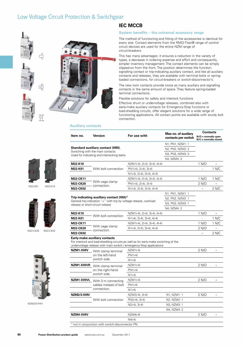
System benefits – the universal accessory range
The method of functioning and fitting of the accessories is identical for every size. Contact elements from the RMQ-Titan® range of control circuit devices are used for the entire NZM range of circuit-breakers.
This has many advantages: it ensures a reduction in the variety of types, a decrease in ordering expense and effort and consequently, simpler inventory management. The contact elements can be simply clipped-on from the front. The position determines the function: signalling contact or trip-indicating auxiliary contact, and like all auxiliary contacts and releases, they are available with terminal bolts or spring-loaded connections, for circuit-breakers or switch-disconnector’s.
The new twin contacts provide twice as many auxiliary and signalling contacts in the same amount of space. They feature spring-loaded terminal connections.
Flexible solutions for safety and interlock functionsEffective shunt or undervoltage releases, combined also with early-make auxiliary contacts for Emergency-Stop functions or load-shedding circuits, offer elegant solutions for a wide range of functioning applications. All contact points are available with sturdy bolt connection.
Item no. Version For use withMax no. of auxilary contacts per switch
ContactsN/O = normally openN/C = normally closed
Standard auxiliary contact (HIN). Switching with the main contacts. Used for indicating and interlocking tasks.
N1, PN1, NZM1: 1
N2, PN2, NZM2: 2
N3, PN3, NZM3: 3
N4, NZM4: 3
M22-K10
With bolt connection
NZM1(-4), 2(-4), 3(-4), 4(-4) 1 N/O –M22-K01 PN1(-4), 2(-4), 3(-4) - 1 N/C
N1(-4), 2(-4), 3(-4), 4(-4)
M22-CK11With cage clamp connection.
NZM1(-4), 2(-4), 3(-4), 4(-4) 1 N/O 1 N/CM22-CK20 PN1(-4), 2(-4), 3(-4) 2 N/O –M22-CK02 N1(-4), 2(-4), 3(-4), 4(-4) – 2 N/C
Trip indicating auxiliary contact (HIA)1)
General trip indication “+” with trip by voltage release, overload release or short-circuit release
N1, PN1, NZM1: 1
N2, PN2, NZM2: 1
N3, PN3, NZM3: 1
N4, NZM4: 2
M22-K10With bolt connection
NZM1(-4), 2(-4), 3(-4), 4(-4) 1 N/O –M22-K01 N1(-4), 2(-4), 3(-4), 4(-4) - 1 N/CM22-CK11
With cage clamp connection.
NZM1(-4), 2(-4), 3(-4), 4(-4) 1 N/O 1 N/CM22-CK20 N1(-4), 2(-4), 3(-4), 4(-4) 2 N/O –M22-CK02 – 2 N/CEarly-make auxiliary contactsFor interlock and load-shedding circuits,as well as for early-make switching of the undervoltage release with main switch / emergency-Stop applications
NZM1-XHIV With clamp terminal on the left-hand switch side.
NZM1(-4) 2 N/O –PN1(-4)
N1(-4)
NZM1-XHIVR With clamp terminal on the right-hand switch side.
NZM1(-4) 2 N/O –PN1(-4)
N1(-4)
NZM1-XHIVL With 3 m connecting cables instead of bolt connection.
NZM1(-4) 2 N/O –PN1(-4)
N1(-4)
NZM2/3-XHIV
With bolt connection
NZM2(-4), 3(-4) N1, NZM1: 1 2 N/O –PN2(-4), 3(-4) N2, NZM2: 1
N2(-4), 3(-4) N3, NZM3: 1
N4, NZM4: 2
NZM4-XHIV NZM4(-4) 2 N/O –N4(-4)
1) not in conjunction with switch-disconnector PN
Auxiliary contacts
M22-K01
M22-CK20
M22-K10
M22-CK02
NZM2/3-XHIV
91Power Distribution product guide eatoncorp.com.au December 2017
IEC MCCB
Low Voltage Circuit Protection & Switchgear
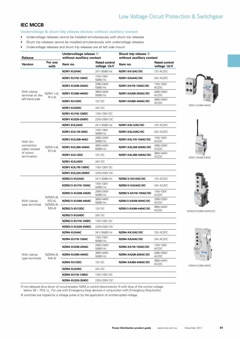
Undervoltage & shunt trip release devices without auxiliary contact• Undervoltage releases cannot be installed simultaneously with shunt trip releases
• Shunt trip releases cannot be installed simultaneously with undervoltage releases
• Undervoltage releases and shunt trip releases are all left side mount
non-delayed shut down of circuit-breaker NZM or switch-disconnector N with drop of the control voltage below 35 – 70% US. For use with Emergency-Stop devices in conjunction with Emergency-Stop button.
switches are tripped by a voltage pulse or by the application of uninterrupted voltage.
ReleaseUndervoltage release without auxiliary contact
Shunt trip release without auxiliary contact
VersionFor use
withItem no. Rated control
voltage Us V Item no. Rated control voltage Us V
With clamp terminal on the left-hand side
NZM1 (-4), N1(-4)
NZM1-XU24AC 24 V 50/60 Hz NZM1-XA12AC/DC 12V AC/DC
NZM1-XU110-130AC110V-130V 50/60 Hz
NZM1-XA24AC/DC 24V AC/DC
NZM1-XU208-240AC208V-240V 50/60 Hz
NZM1-XA110-130AC/DC110V-130V AC/DC
NZM1-XU380-440AC380V-440V 50/60 Hz
NZM1-XA208-250AC/DC208V-250V AC/DC
NZM1-XU12DC 12V DC NZM1-XA380-440AC/DC380V-440V AC/DC
NZM1-XU24DC 24V DC
NZM1-XU110-130DC 110V-130V DC
NZM1-XU220-250DC 220V-250V DC
With 3m connection cable instead of screw termination
NZM1(-4), N1(-4)
NZM1-XUL24AC 24 V 50/60 Hz NZM1-XAL12AC/DC 12V AC/DC
NZM1-XUL110-30AC110V-130V 50/60 Hz
NZM1-XAL24AC/DC 24V AC/DC
NZM1-XUL208-40AC208V-240V 50/60 Hz
NZM1-XAL110-130AC/DC110V-130V AC/DC
NZM1-XUL380-440AC380V-440V 50/60 Hz
NZM1-XAL208-250AC/DC208V-250V AC/DC
NZM1-XUL12DC 12V DC NZM1-XAL380-440AC/DC380V-440V AC/DC
NZM1-XUL24DC 24V DC
NZM1-XUL110-130DC 110V-130V DC
NZM1-XUL220-250DC 220V-250V DC
With clamp-type terminals
NZM2(-4), N2(-4),
NZM3(-4), N3(-4)
NZM2/3-XU24AC 24 V 50/60 Hz NZM2/3-XA12AC/DC 12V AC/DC
NZM2/3-XU110-130AC110V-130V 50/60 Hz
NZM2/3-XA24AC/DC 24V AC/DC
NZM2/3-XU208-240AC208V-240V 50/60 Hz
NZM2/3-XA110-130AC/DC110V-130V AC/DC
NZM2/3-XU380-440AC380V-440V 50/60 Hz
NZM2/3-XA208-250AC/DC208V-250V AC/DC
NZM2/3-XU12DC 12V DC NZM2/3-XA380-440AC/DC380V-440V AC/DC
NZM2/3-XU24DC 24V DC
NZM2/3-XU110-130DC 110V-130V DC
NZM2/3-XU220-250DC 220V-250V DC
With clamp-type terminals
NZM4(-4), N4(-4)
NZM4-XU24AC 24 V 50/60 Hz NZM4-XA12AC/DC 12V AC/DC
NZM4-XU110-130AC110V-130V 50/60 Hz
NZM4-XA24AC/DC 24V AC/DC
NZM4-XU208-240AC208V-240V 50/60 Hz
NZM4-XA110-130AC/DC110V-130V AC/DC
NZM4-XU380-440AC380V-440V 50/60 Hz
NZM4-XA208-250AC/DC208V-250V AC/DC
NZM4-XU12DC 12V DC NZM4-XA380-440AC/DC380V-440V AC/DC
NZM4-XU24DC 24V DC
NZM4-XU110-130DC 110V-130V DC
NZM4-XU220-250DC 220V-250V DC
NZM1-XU380-440AC
NZM1-XA208-240AC
NZM2/3-XA380-440AC/DC
NZM4-XU380-440AC
92 Power Distribution product guide eatoncorp.com.au December 2017
IEC MCCB
Low Voltage Circuit Protection & Switchgear
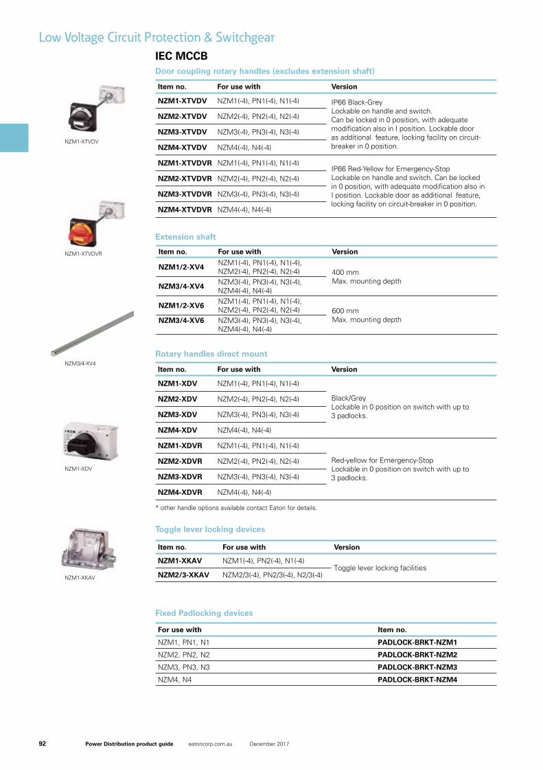
Toggle lever locking devices
Item no. For use with Version
NZM1-XKAV NZM1(-4), PN2(-4), N1(-4)Toggle lever locking facilities
NZM2/3-XKAV NZM2/3(-4), PN2/3(-4), N2/3(-4)
Item no. For use with Version
NZM1-XTVDV NZM1(-4), PN1(-4), N1(-4) IP66 Black-Grey Lockable on handle and switch. Can be locked in 0 position, with adequate modification also in I position. Lockable door as additional feature, locking facility on circuit-breaker in 0 position.
NZM2-XTVDV NZM2(-4), PN2(-4), N2(-4)
NZM3-XTVDV NZM3(-4), PN3(-4), N3(-4)
NZM4-XTVDV NZM4(-4), N4(-4)
NZM1-XTVDVR NZM1(-4), PN1(-4), N1(-4)IP66 Red-Yellow for Emergency-StopLockable on handle and switch. Can be locked in 0 position, with adequate modification also in I position. Lockable door as additional feature, locking facility on circuit-breaker in 0 position.
NZM2-XTVDVR NZM2(-4), PN2(-4), N2(-4)
NZM3-XTVDVR NZM3(-4), PN3(-4), N3(-4)
NZM4-XTVDVR NZM4(-4), N4(-4)
Door coupling rotary handles (excludes extension shaft)
Item no. For use with Version
NZM1-XDV NZM1(-4), PN1(-4), N1(-4)
Black/Grey Lockable in 0 position on switch with up to 3 padlocks.
NZM2-XDV NZM2(-4), PN2(-4), N2(-4)
NZM3-XDV NZM3(-4), PN3(-4), N3(-4)
NZM4-XDV NZM4(-4), N4(-4)
NZM1-XDVR NZM1(-4), PN1(-4), N1(-4)
Red-yellow for Emergency-StopLockable in 0 position on switch with up to 3 padlocks.
NZM2-XDVR NZM2(-4), PN2(-4), N2(-4)
NZM3-XDVR NZM3(-4), PN3(-4), N3(-4)
NZM4-XDVR NZM4(-4), N4(-4)
Rotary handles direct mount
* other handle options available contact Eaton for details.
Fixed Padlocking devices
For use with Item no.
NZM1, PN1, N1 PADLOCK-BRKT-NZM1
NZM2, PN2, N2 PADLOCK-BRKT-NZM2
NZM3, PN3, N3 PADLOCK-BRKT-NZM3
NZM4, N4 PADLOCK-BRKT-NZM4
05/07/2015 260174 - HPL-ED2015 V12.0 EN 1 / 3
Door�coupling�rotary�handle,�lockable�on�the�handle,�size�2
Part�no. NZM2-XTVDVArticle�no. 260174
Similar to illustration
Delivery�programmeFunction Standard, black/grey
Protection class IP66UL/CSA Type 4X, Type 12
Locking facility lockable on the handle on the switch using up to 3 padlocksModifiable on handle in I position as wellWith door interlock
Door interlock Not defeated in the locked OFF and ON positionsCan be modified in the unlocked ON positionCan be modified such that it can be defeated from the outside using a screwdriverDoor can be opened in OFF
Project planning information External warning plate/designation label can be clipped on.Complete including rotary drive and coupling partsExtension shaft additionally required.
For use with NZM2(-4), PN2(-4), N(S)2(-4)
lockable double
Notes
Circuit‐breaker can also be installed in a lying position 90 ° left/right, with the handle still in the same position.
Design�verification�as�per�IEC/EN�61439IEC/EN 61439 design verification
10.2 Strength of materials and parts
10.2.2 Corrosion resistance Meets the product standard's requirements.
10.2.3.1 Verification of thermal stability of enclosures Meets the product standard's requirements.
10.2.3.2 Verification of resistance of insulating materials to normal heat Meets the product standard's requirements.
10.2.3.3 Verification of resistance of insulating materials to abnormal heatand fire due to internal electric effects
Meets the product standard's requirements.
10.2.4 Resistance to ultra-violet (UV) radiation Meets the product standard's requirements.
10.2.5 Lifting Does not apply, since the entire switchgear needs to be evaluated.
10.2.6 Mechanical impact Does not apply, since the entire switchgear needs to be evaluated.
10.2.7 Inscriptions Meets the product standard's requirements.
10.3 Degree of protection of ASSEMBLIES Does not apply, since the entire switchgear needs to be evaluated.
10.4 Clearances and creepage distances Meets the product standard's requirements.
10.5 Protection against electric shock Does not apply, since the entire switchgear needs to be evaluated.
10.6 Incorporation of switching devices and components Does not apply, since the entire switchgear needs to be evaluated.
10.7 Internal electrical circuits and connections Is the panel builder's responsibility.
10.8 Connections for external conductors Is the panel builder's responsibility.
10.9 Insulation properties
10.9.2 Power-frequency electric strength Is the panel builder's responsibility.
10.9.3 Impulse withstand voltage Is the panel builder's responsibility.
10.9.4 Testing of enclosures made of insulating material Is the panel builder's responsibility.
10.10 Temperature rise The panel builder is responsible for the temperature rise calculation. Eaton willprovide heat dissipation data for the devices.
10.11 Short-circuit rating Is the panel builder's responsibility. The specifications for the switchgear must beobserved.
10.12 Electromagnetic compatibility Is the panel builder's responsibility. The specifications for the switchgear must beobserved.
10.13 Mechanical function The device meets the requirements, provided the information in the instructionleaflet (IL) is observed.
Technical�data�ETIM�5.0Low-voltage industrial components (EG000017) / Handle for power circuit breaker (EC000229)
Electric engineering, automation, process control engineering / Low-voltage switch technology / Circuit breaker (LV < 1 kV) / Handle for switch devices (ecl@ss8-27-37-04-14 [AKF012010])
NZM1-XTVDV
05/07/2015 260180 - HPL-ED2015 V12.0 EN 1 / 4
Door�coupling�rotary�handle,�red-yellow�for�emergency�switching�off,size�2
Part�no. NZM2-XTVDVRArticle�no. 260180
Similar to illustration
Delivery�programmeFunction Red-yellow for emergency switching off
Protection class IP66UL/CSA Type 4X, Type 12
Locking facility lockable on the handle on the switch using up to 3 padlocksWith door interlock
Door interlock Not defeated in the locked OFF position.Can be modified in the unlocked ON positionCan be modified such that it can be defeated from the outside using a screwdriverDoor can be opened in OFF
Project planning information External warning plate/designation label can be clipped on.Complete including rotary drive and coupling partsExtension shaft additionally required.
For use with NZM2(-4), PN2(-4), N(S)2(-4)
lockable double
Notes
Circuit‐breaker can also be installed in a lying position 90 ° left/right, with the handle still in the same position.
Design�verification�as�per�IEC/EN�61439IEC/EN 61439 design verification
10.2 Strength of materials and parts
10.2.2 Corrosion resistance Meets the product standard's requirements.
10.2.3.1 Verification of thermal stability of enclosures Meets the product standard's requirements.
10.2.3.2 Verification of resistance of insulating materials to normal heat Meets the product standard's requirements.
10.2.3.3 Verification of resistance of insulating materials to abnormal heatand fire due to internal electric effects
Meets the product standard's requirements.
10.2.4 Resistance to ultra-violet (UV) radiation Meets the product standard's requirements.
10.2.5 Lifting Does not apply, since the entire switchgear needs to be evaluated.
10.2.6 Mechanical impact Does not apply, since the entire switchgear needs to be evaluated.
10.2.7 Inscriptions Meets the product standard's requirements.
10.3 Degree of protection of ASSEMBLIES Does not apply, since the entire switchgear needs to be evaluated.
10.4 Clearances and creepage distances Meets the product standard's requirements.
10.5 Protection against electric shock Does not apply, since the entire switchgear needs to be evaluated.
10.6 Incorporation of switching devices and components Does not apply, since the entire switchgear needs to be evaluated.
10.7 Internal electrical circuits and connections Is the panel builder's responsibility.
10.8 Connections for external conductors Is the panel builder's responsibility.
10.9 Insulation properties
10.9.2 Power-frequency electric strength Is the panel builder's responsibility.
10.9.3 Impulse withstand voltage Is the panel builder's responsibility.
10.9.4 Testing of enclosures made of insulating material Is the panel builder's responsibility.
10.10 Temperature rise The panel builder is responsible for the temperature rise calculation. Eaton willprovide heat dissipation data for the devices.
10.11 Short-circuit rating Is the panel builder's responsibility. The specifications for the switchgear must beobserved.
10.12 Electromagnetic compatibility Is the panel builder's responsibility. The specifications for the switchgear must beobserved.
10.13 Mechanical function The device meets the requirements, provided the information in the instructionleaflet (IL) is observed.
Technical�data�ETIM�5.0Low-voltage industrial components (EG000017) / Handle for power circuit breaker (EC000229)
NZM1-XTVDVR
NZM3/4-XV4
05/07/2015 260127 - HPL-ED2015 V12.0 EN 1 / 2
Rotary�handle,�lockable,�size�2
Part�no. NZM2-XDVArticle�no. 260127
Similar to illustration
Delivery�programmeFunction Standard, black/grey
Protection class IP66UL/CSA Type 4X, Type 12
Locking facility lockable on the 0 position on the switch using up to 3 padlocks
Project planning information Complete with rotary driveCan be combined with insulating surroundMODAN handle position detection by wire release can be retrofitted
Actuation Rotary handle
For use with NZM2(-4), PN2(-4), N(S)2(-4)
Notes
Circuit‐breaker can also be installed in a lying position 90 ° left/right, with the handle still in the same position.
Design�verification�as�per�IEC/EN�61439IEC/EN 61439 design verification
10.2 Strength of materials and parts
10.2.2 Corrosion resistance Meets the product standard's requirements.
10.2.3.1 Verification of thermal stability of enclosures Meets the product standard's requirements.
10.2.3.2 Verification of resistance of insulating materials to normal heat Meets the product standard's requirements.
10.2.3.3 Verification of resistance of insulating materials to abnormal heatand fire due to internal electric effects
Meets the product standard's requirements.
10.2.4 Resistance to ultra-violet (UV) radiation Meets the product standard's requirements.
10.2.5 Lifting Does not apply, since the entire switchgear needs to be evaluated.
10.2.6 Mechanical impact Does not apply, since the entire switchgear needs to be evaluated.
10.2.7 Inscriptions Meets the product standard's requirements.
10.3 Degree of protection of ASSEMBLIES Does not apply, since the entire switchgear needs to be evaluated.
10.4 Clearances and creepage distances Meets the product standard's requirements.
10.5 Protection against electric shock Does not apply, since the entire switchgear needs to be evaluated.
10.6 Incorporation of switching devices and components Does not apply, since the entire switchgear needs to be evaluated.
10.7 Internal electrical circuits and connections Is the panel builder's responsibility.
10.8 Connections for external conductors Is the panel builder's responsibility.
10.9 Insulation properties
10.9.2 Power-frequency electric strength Is the panel builder's responsibility.
10.9.3 Impulse withstand voltage Is the panel builder's responsibility.
10.9.4 Testing of enclosures made of insulating material Is the panel builder's responsibility.
10.10 Temperature rise The panel builder is responsible for the temperature rise calculation. Eaton willprovide heat dissipation data for the devices.
10.11 Short-circuit rating Is the panel builder's responsibility. The specifications for the switchgear must beobserved.
10.12 Electromagnetic compatibility Is the panel builder's responsibility. The specifications for the switchgear must beobserved.
10.13 Mechanical function The device meets the requirements, provided the information in the instructionleaflet (IL) is observed.
Technical�data�ETIM�5.0Low-voltage industrial components (EG000017) / Handle for power circuit breaker (EC000229)
Electric engineering, automation, process control engineering / Low-voltage switch technology / Circuit breaker (LV < 1 kV) / Handle for switch devices (ecl@ss8-27-37-04-14 [AKF012010])
Lockable Yes
Colour Black
Suitable for emergency stop No
With axe No
NZM1-XDV
05/07/2015 260199 - HPL-ED2015 V12.0 EN 1 / 2
Toggle�lever�locking�device
Part�no. NZM1-XKAVArticle�no. 260199
Delivery�programme Toggle lever locking device
Off position lockable using up to 3 padlocks (hasp thickness 4 - 8 mm)
Description Toggle lever interlock device
OFF position can be locked with up to 3 padlocks (4 - 8 mm hasp thickness)
Not UL/CSA-approved
Cannot be combined with insulating surround
Accessories Toggle lever interlock device
For use with NZM1(-4)NZM1(-1)PN1(-4), N(S)1(-4)
Design�verification�as�per�IEC/EN�61439IEC/EN 61439 design verification
10.2 Strength of materials and parts
10.2.2 Corrosion resistance Meets the product standard's requirements.
10.2.3.1 Verification of thermal stability of enclosures Meets the product standard's requirements.
10.2.3.2 Verification of resistance of insulating materials to normal heat Meets the product standard's requirements.
10.2.3.3 Verification of resistance of insulating materials to abnormal heatand fire due to internal electric effects
Meets the product standard's requirements.
10.2.4 Resistance to ultra-violet (UV) radiation Meets the product standard's requirements.
10.2.5 Lifting Does not apply, since the entire switchgear needs to be evaluated.
10.2.6 Mechanical impact Does not apply, since the entire switchgear needs to be evaluated.
10.2.7 Inscriptions Meets the product standard's requirements.
10.3 Degree of protection of ASSEMBLIES Does not apply, since the entire switchgear needs to be evaluated.
10.4 Clearances and creepage distances Meets the product standard's requirements.
10.5 Protection against electric shock Does not apply, since the entire switchgear needs to be evaluated.
10.6 Incorporation of switching devices and components Does not apply, since the entire switchgear needs to be evaluated.
10.7 Internal electrical circuits and connections Is the panel builder's responsibility.
10.8 Connections for external conductors Is the panel builder's responsibility.
10.9 Insulation properties
10.9.2 Power-frequency electric strength Is the panel builder's responsibility.
10.9.3 Impulse withstand voltage Is the panel builder's responsibility.
10.9.4 Testing of enclosures made of insulating material Is the panel builder's responsibility.
10.10 Temperature rise The panel builder is responsible for the temperature rise calculation. Eaton willprovide heat dissipation data for the devices.
10.11 Short-circuit rating Is the panel builder's responsibility. The specifications for the switchgear must beobserved.
10.12 Electromagnetic compatibility Is the panel builder's responsibility. The specifications for the switchgear must beobserved.
10.13 Mechanical function The device meets the requirements, provided the information in the instructionleaflet (IL) is observed.
Technical�data�ETIM�5.0Low-voltage industrial components (EG000017) / Handle for power circuit breaker (EC000229)
Electric engineering, automation, process control engineering / Low-voltage switch technology / Circuit breaker (LV < 1 kV) / Handle for switch devices (ecl@ss8-27-37-04-14 [AKF012010])
Lockable Yes
Colour -
Suitable for emergency stop No
With axe No
Suitable for power circuit breaker Yes
NZM1-XKAV
Extension shaft
Item no. For use with Version
NZM1/2-XV4NZM1(-4), PN1(-4), N1(-4), NZM2(-4), PN2(-4), N2(-4) 400 mm
Max. mounting depthNZM3/4-XV4
NZM3(-4), PN3(-4), N3(-4), NZM4(-4), N4(-4)
NZM1/2-XV6NZM1(-4), PN1(-4), N1(-4), NZM2(-4), PN2(-4), N2(-4) 600 mm
Max. mounting depthNZM3/4-XV6 NZM3(-4), PN3(-4), N3(-4), NZM4(-4), N4(-4)
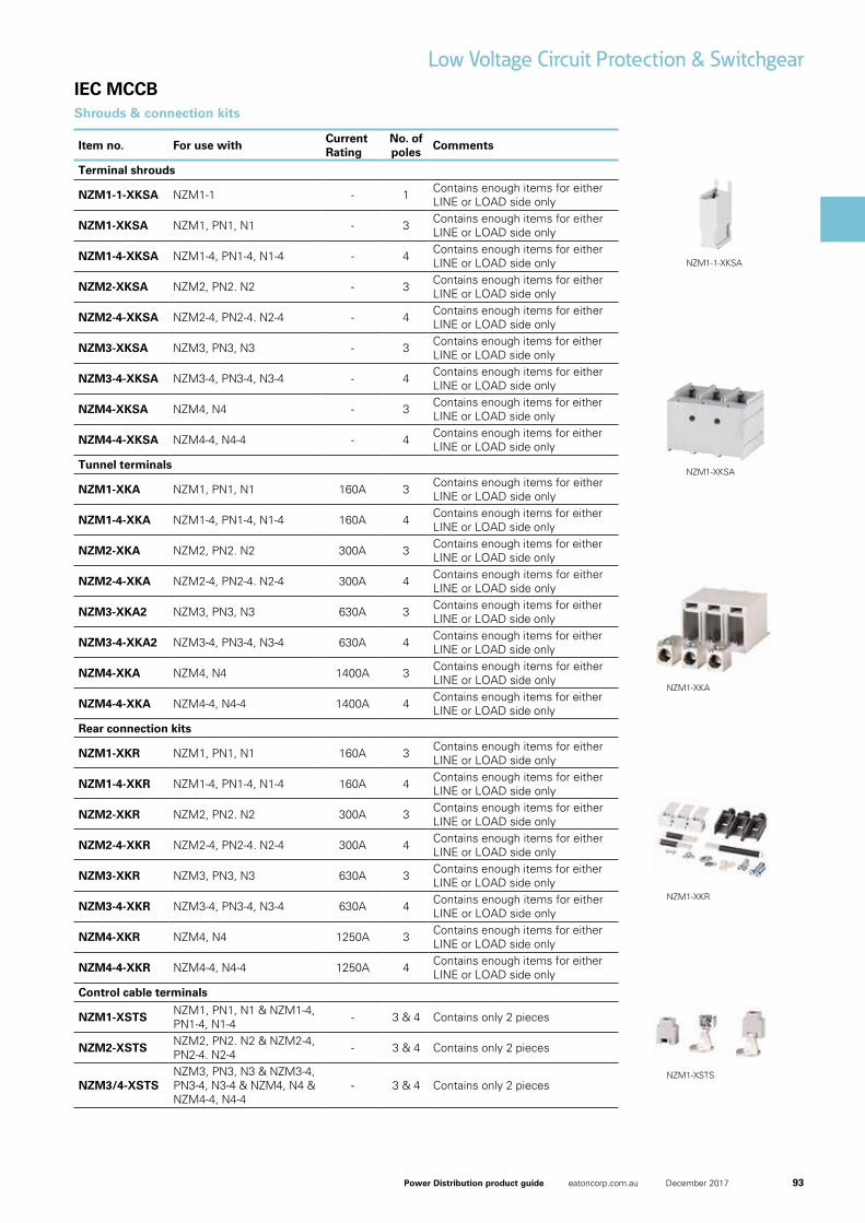
93Power Distribution product guide eatoncorp.com.au December 2017
IEC MCCB
Low Voltage Circuit Protection & Switchgear
Shrouds & connection kits
Item no. For use withCurrent Rating
No. of poles
Comments
Terminal shrouds
NZM1-1-XKSA NZM1-1 - 1 Contains enough items for either LINE or LOAD side only
NZM1-XKSA NZM1, PN1, N1 - 3 Contains enough items for either LINE or LOAD side only
NZM1-4-XKSA NZM1-4, PN1-4, N1-4 - 4 Contains enough items for either LINE or LOAD side only
NZM2-XKSA NZM2, PN2. N2 - 3 Contains enough items for either LINE or LOAD side only
NZM2-4-XKSA NZM2-4, PN2-4. N2-4 - 4 Contains enough items for either LINE or LOAD side only
NZM3-XKSA NZM3, PN3, N3 - 3 Contains enough items for either LINE or LOAD side only
NZM3-4-XKSA NZM3-4, PN3-4, N3-4 - 4 Contains enough items for either LINE or LOAD side only
NZM4-XKSA NZM4, N4 - 3 Contains enough items for either LINE or LOAD side only
NZM4-4-XKSA NZM4-4, N4-4 - 4 Contains enough items for either LINE or LOAD side only
Tunnel terminals
NZM1-XKA NZM1, PN1, N1 160A 3 Contains enough items for either LINE or LOAD side only
NZM1-4-XKA NZM1-4, PN1-4, N1-4 160A 4 Contains enough items for either LINE or LOAD side only
NZM2-XKA NZM2, PN2. N2 300A 3 Contains enough items for either LINE or LOAD side only
NZM2-4-XKA NZM2-4, PN2-4. N2-4 300A 4 Contains enough items for either LINE or LOAD side only
NZM3-XKA2 NZM3, PN3, N3 630A 3 Contains enough items for either LINE or LOAD side only
NZM3-4-XKA2 NZM3-4, PN3-4, N3-4 630A 4 Contains enough items for either LINE or LOAD side only
NZM4-XKA NZM4, N4 1400A 3 Contains enough items for either LINE or LOAD side only
NZM4-4-XKA NZM4-4, N4-4 1400A 4 Contains enough items for either LINE or LOAD side only
Rear connection kits
NZM1-XKR NZM1, PN1, N1 160A 3 Contains enough items for either LINE or LOAD side only
NZM1-4-XKR NZM1-4, PN1-4, N1-4 160A 4 Contains enough items for either LINE or LOAD side only
NZM2-XKR NZM2, PN2. N2 300A 3 Contains enough items for either LINE or LOAD side only
NZM2-4-XKR NZM2-4, PN2-4. N2-4 300A 4 Contains enough items for either LINE or LOAD side only
NZM3-XKR NZM3, PN3, N3 630A 3 Contains enough items for either LINE or LOAD side only
NZM3-4-XKR NZM3-4, PN3-4, N3-4 630A 4 Contains enough items for either LINE or LOAD side only
NZM4-XKR NZM4, N4 1250A 3 Contains enough items for either LINE or LOAD side only
NZM4-4-XKR NZM4-4, N4-4 1250A 4 Contains enough items for either LINE or LOAD side only
Control cable terminals
NZM1-XSTSNZM1, PN1, N1 & NZM1-4, PN1-4, N1-4 - 3 & 4 Contains only 2 pieces
NZM2-XSTSNZM2, PN2. N2 & NZM2-4, PN2-4. N2-4 - 3 & 4 Contains only 2 pieces
NZM3/4-XSTSNZM3, PN3, N3 & NZM3-4, PN3-4, N3-4 & NZM4, N4 & NZM4-4, N4-4
- 3 & 4 Contains only 2 pieces
NZM1-1-XKSA
NZM1-XKSA
04/24/2015 271457 - HPL-ED2015 V12.0 EN 1 / 3
Tunnel�terminal,�3p,�1�page,�size�2
Part�no. NZM2-XKAArticle�no. 271457
Similar to illustration
Delivery�programmeNumber of conductors 3 pole
Accessories Tunnel terminal
Rated current In A Cu 300, Al 250
For use with NZM2, PN2, N(S)2
Terminal�capacities
Type of conductor
Cu/Al cable Copper cableAl cable
Terminal capacities
flexible mm2 2 x 16 - 1851 x 16 - 185Up to 240 mm² can be connected depending on the cable manufacturer.
AWG/kcmil mm2 1 x 6 - 350
Notes
Type contains parts for a terminal located at top or bottom for 3 or 4-pole circuit-breakers.
A standard with control circuit terminal for 1 x 0.75 - 2.5 mm2 (18 - 14 AWG) or 2 x 0.75 - 1.5 mm2 (18 - 16 AWG) copper conductors.
Fitted outside the switch housing
Use with flexible and highly flexible conductors ferrules. Maximum specified cross-section can only be connected when stranded and without ferrules.
Mounting of the cover NZM2(-4)-XKSA obligatory (supplied).
Design�verification�as�per�IEC/EN�61439IEC/EN 61439 design verification
10.2 Strength of materials and parts
10.2.2 Corrosion resistance Meets the product standard's requirements.
10.2.3.1 Verification of thermal stability of enclosures Meets the product standard's requirements.
10.2.3.2 Verification of resistance of insulating materials to normal heat Meets the product standard's requirements.
10.2.3.3 Verification of resistance of insulating materials to abnormal heatand fire due to internal electric effects
Meets the product standard's requirements.
10.2.4 Resistance to ultra-violet (UV) radiation Meets the product standard's requirements.
10.2.5 Lifting Does not apply, since the entire switchgear needs to be evaluated.
10.2.6 Mechanical impact Does not apply, since the entire switchgear needs to be evaluated.
10.2.7 Inscriptions Meets the product standard's requirements.
10.3 Degree of protection of ASSEMBLIES Does not apply, since the entire switchgear needs to be evaluated.
10.4 Clearances and creepage distances Meets the product standard's requirements.
10.5 Protection against electric shock Does not apply, since the entire switchgear needs to be evaluated.
10.6 Incorporation of switching devices and components Does not apply, since the entire switchgear needs to be evaluated.
10.7 Internal electrical circuits and connections Is the panel builder's responsibility.
10.8 Connections for external conductors Is the panel builder's responsibility.
10.9 Insulation properties
10.9.2 Power-frequency electric strength Is the panel builder's responsibility.
10.9.3 Impulse withstand voltage Is the panel builder's responsibility.
10.9.4 Testing of enclosures made of insulating material Is the panel builder's responsibility.
10.10 Temperature rise The panel builder is responsible for the temperature rise calculation. Eaton willprovide heat dissipation data for the devices.
10.11 Short-circuit rating Is the panel builder's responsibility. The specifications for the switchgear must beobserved.
10.12 Electromagnetic compatibility Is the panel builder's responsibility. The specifications for the switchgear must beobserved.
NZM1-XKA
04/24/2015 266765 - HPL-ED2015 V12.0 EN 1 / 2
Connection,�on�rear,�3p,�1�switch�side
Part�no. NZM2-XKRArticle�no. 266765
Delivery�programmeNumber of conductors 3 pole
Accessories Connection on rear
Rated current In A Cu 300, Al 250
For use with NZM2, PN2, N2
Terminal�capacities
Type of conductor
Cu/Al cable Copper cable lugsAluminium cable lug
Terminal capacities
flexible mm2 1 x 4 - 1852 x 4 - 701 x 10 - 502 x 10 - 50
Terminal�capacities
Cu strip (number of segments x width x segment thickness) mm 2 x 16 x 0.8
6 x 24 x 0.5
Copper busbar width x thickness Breite mm 16 x 5
24 x 8
Notes
Type suffix and type contain parts for a circuit-breaker side at top or bottom for 3 or 4-pole circuit-breakers.
O = for fitting at the top
U = for fitting at the bottom
Design�verification�as�per�IEC/EN�61439IEC/EN 61439 design verification
10.2 Strength of materials and parts
10.2.2 Corrosion resistance Meets the product standard's requirements.
10.2.3.1 Verification of thermal stability of enclosures Meets the product standard's requirements.
10.2.3.2 Verification of resistance of insulating materials to normal heat Meets the product standard's requirements.
10.2.3.3 Verification of resistance of insulating materials to abnormal heatand fire due to internal electric effects
Meets the product standard's requirements.
10.2.4 Resistance to ultra-violet (UV) radiation Meets the product standard's requirements.
10.2.5 Lifting Does not apply, since the entire switchgear needs to be evaluated.
10.2.6 Mechanical impact Does not apply, since the entire switchgear needs to be evaluated.
10.2.7 Inscriptions Meets the product standard's requirements.
10.3 Degree of protection of ASSEMBLIES Does not apply, since the entire switchgear needs to be evaluated.
10.4 Clearances and creepage distances Meets the product standard's requirements.
10.5 Protection against electric shock Does not apply, since the entire switchgear needs to be evaluated.
10.6 Incorporation of switching devices and components Does not apply, since the entire switchgear needs to be evaluated.
10.7 Internal electrical circuits and connections Is the panel builder's responsibility.
10.8 Connections for external conductors Is the panel builder's responsibility.
10.9 Insulation properties
10.9.2 Power-frequency electric strength Is the panel builder's responsibility.
10.9.3 Impulse withstand voltage Is the panel builder's responsibility.
10.9.4 Testing of enclosures made of insulating material Is the panel builder's responsibility.
10.10 Temperature rise The panel builder is responsible for the temperature rise calculation. Eaton willprovide heat dissipation data for the devices.
10.11 Short-circuit rating Is the panel builder's responsibility. The specifications for the switchgear must beobserved.
10.12 Electromagnetic compatibility Is the panel builder's responsibility. The specifications for the switchgear must beobserved.
NZM1-XKR
04/24/2015 260156 - HPL-ED2015 V12.0 EN 1 / 2
Control�circuit�terminal,�screw�connection
Part�no. NZM2-XSTSArticle�no. 260156
Similar to illustration
Delivery�programmeAccessories Control circuit terminal
For use with NZM2(-4), PN2(-4), N(S)2(-4)
Terminal�capacities
Type of conductor
Cu/Al cable Screw connection
Terminal capacities
flexible mm2 1 x 0.75 - 2.52 x 0.75 - 1.5
AWG/kcmil mm2 1 x 18 - 142 x 18 - 16
Notes
Type contains parts for two terminal locations located at top or bottom for 3 or 4-pole circuit-breakers.
Included as standard with tunnel terminal
Degree of protection IP1X
NZM-XSTK cannot be combined with NZM2(-4)-XIPK IP2X protection against contact with a finger.
Height or thickness of the control circuit terminals:
NZM‐XSTK = 2 mm
NZM‐XSTS = 2 mm
Design�verification�as�per�IEC/EN�61439IEC/EN 61439 design verification
10.2 Strength of materials and parts
10.2.2 Corrosion resistance Meets the product standard's requirements.
10.2.3.1 Verification of thermal stability of enclosures Meets the product standard's requirements.
10.2.3.2 Verification of resistance of insulating materials to normal heat Meets the product standard's requirements.
10.2.3.3 Verification of resistance of insulating materials to abnormal heatand fire due to internal electric effects
Meets the product standard's requirements.
10.2.4 Resistance to ultra-violet (UV) radiation Meets the product standard's requirements.
10.2.5 Lifting Does not apply, since the entire switchgear needs to be evaluated.
10.2.6 Mechanical impact Does not apply, since the entire switchgear needs to be evaluated.
10.2.7 Inscriptions Meets the product standard's requirements.
10.3 Degree of protection of ASSEMBLIES Does not apply, since the entire switchgear needs to be evaluated.
10.4 Clearances and creepage distances Meets the product standard's requirements.
10.5 Protection against electric shock Does not apply, since the entire switchgear needs to be evaluated.
10.6 Incorporation of switching devices and components Does not apply, since the entire switchgear needs to be evaluated.
10.7 Internal electrical circuits and connections Is the panel builder's responsibility.
10.8 Connections for external conductors Is the panel builder's responsibility.
10.9 Insulation properties
10.9.2 Power-frequency electric strength Is the panel builder's responsibility.
10.9.3 Impulse withstand voltage Is the panel builder's responsibility.
10.9.4 Testing of enclosures made of insulating material Is the panel builder's responsibility.
10.10 Temperature rise The panel builder is responsible for the temperature rise calculation. Eaton willprovide heat dissipation data for the devices.
10.11 Short-circuit rating Is the panel builder's responsibility. The specifications for the switchgear must beobserved.
10.12 Electromagnetic compatibility Is the panel builder's responsibility. The specifications for the switchgear must beobserved.
10.13 Mechanical function The device meets the requirements, provided the information in the instructionleaflet (IL) is observed.
NZM1-XSTS
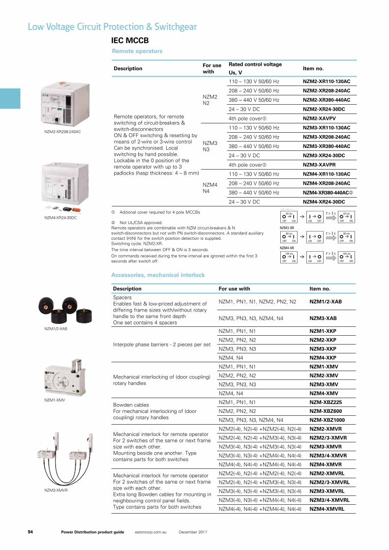
94 Power Distribution product guide eatoncorp.com.au December 2017
IEC MCCB
Low Voltage Circuit Protection & Switchgear
Accessories, mechanical interlock
Description For use with Item no.
Spacers Enables fast & low-priced adjustment of differing frame sizes with/without rotary handle to the same front depth One set contains 4 spacers
NZM1, PN1, N1, NZM2, PN2, N2 NZM1/2-XAB
NZM3, PN3, N3, NZM4, N4 NZM3-XAB
Interpole phase barriers - 2 pieces per set
NZM1, PN1, N1 NZM1-XKP
NZM2, PN2, N2 NZM2-XKP
NZM3, PN3, N3 NZM3-XKP
NZM4, N4 NZM4-XKP
Mechanical interlocking of (door coupling) rotary handles
NZM1, PN1, N1 NZM1-XMV
NZM2, PN2, N2 NZM2-XMV
NZM3, PN3, N3 NZM3-XMV
NZM4, N4 NZM4-XMV
Bowden cables For mechanical interlocking of (door coupling) rotary handles
NZM1, PN1, N1 NZM-XBZ225
NZM2, PN2, N2 NZM-XBZ600
NZM3, PN3, N3, NZM4, N4 NZM-XBZ1000
Mechanical interlock for remote operator For 2 switches of the same or next frame size with each other. Mounting beside one another. Type contains parts for both switches
NZM2(-4), N2(-4) +NZM2(-4), N2(-4) NZM2-XMVR
NZM2(-4), N2(-4) +NZM3(-4), N3(-4) NZM2/3-XMVR
NZM3(-4), N3(-4) +NZM3(-4), N3(-4) NZM3-XMVR
NZM3(-4), N3(-4) +NZM4(-4), N4(-4) NZM3/4-XMVR
NZM4(-4), N4(-4) +NZM4(-4), N4(-4) NZM4-XMVR
Mechanical interlock for remote operator For 2 switches of the same or next frame size with each other. Extra long Bowden cables for mounting in neighbouring control panel fields. Type contains parts for both switches
NZM2(-4), N2(-4) +NZM2(-4), N2(-4) NZM2-XMVRL
NZM2(-4), N2(-4) +NZM3(-4), N3(-4) NZM2/3-XMVRL
NZM3(-4), N3(-4) +NZM3(-4), N3(-4) NZM3-XMVRL
NZM3(-4), N3(-4) +NZM4(-4), N4(-4) NZM3/4-XMVRL
NZM4(-4), N4(-4) +NZM4(-4), N4(-4) NZM4-XMVRL
9/21
Circ
uit-
brea
kers
, sw
itch
-dis
conn
ecto
rsup
to
1600
A
Moeller SK0211-1158GB-AUS
GST not included
Circuit-breakers, switch-disconnectorsRemote operators
For use with Rated control voltage Part no. Price ($)Productgroup 1
Us
V
Remote operators
For remote switching of circuit-breakers and switch-disconnectors.ON and OFF switching and resetting by means of 2-wire or 3-wire control.Can be synchronized.Local switching by hand possibleLockable in the 0 position of the remote operator with up to 3 padlocks (hasp thickness: 4 – 8 mm)
NZM2N2
110 – 130 V 50/60 Hz NZM2-XR110-130AC 619.40208 – 240 V 50/60 Hz NZM2-XR208-240AC 619.40380 – 440 V 50/60 Hz NZM2-XR380-440AC 619.4024 – 30 V DC NZM2-XR24-30DC 693.80
NZM3N3
110 – 130 V 50/60 Hz NZM3-XR110-130AC 1,232.70208 – 240 V 50/60 Hz NZM3-XR208-240AC 1,232.70380 – 440 V 50/60 Hz NZM3-XR380-440AC 1,232.7024 – 30 V DC NZM3-XR24-30DC 1,468.10
NZM4N4
110 – 130 V 50/60 Hz NZM4-XR110-130AC 2,592.90208 – 240 V 50/60 Hz NZM4-XR208-240AC 2,592.90380 – 440 V 50/60 Hz NZM4-XR380-440AC1) 2,592.9024 – 30 V DC NZM4-XR24-30DC 2,592.90
Notes 1) Not UL/CSA approved.Remote operators are combinable with NZM circuit-breakers and N switch-disconnectors but not with PN switch-disconnectors.A standard auxiliary contact (HIN) for the switch position detection is supplied.Switching cycle:NZM2-XR
NZM3-XR
NZM4-XR
The time interval between OFF and ON is 3 seconds.On commands received during the time interval are ignored within the first 3 seconds after switch off.
r r r60 ms t > 3 s
r 60 ms
OFF ON OFF ONON OFF
r r r80 ms t > 3 s
r 80 ms
OFF ON OFF ONON OFF
r r r100 ms t > 3 s
r 100 ms
OFF ON OFF ONON OFF
SK1158GB-INT.book Seite 21 Donnerstag, 2. Oktober 2008 2:27 14
Aditional cover required for 4 pole MCCBs
Not UL/CSA approved. Remote operators are combinable with NZM circuit-breakers & N switch-disconnectors but not with PN switch-disconnectors. A standard auxiliary contact (HIN) for the switch position detection is supplied. Switching cycle: NZM2-XR. The time interval between OFF & ON is 3 seconds. On commands received during the time interval are ignored within the first 3 seconds after switch off.
Remote operators
DescriptionFor use with
Rated control voltageItem no.
Us, V
Remote operators, for remote switching of circuit-breakers & switch-disconnectors ON & OFF switching & resetting by means of 2-wire or 3-wire control Can be synchronised. Local switching by hand possible. Lockable in the 0 position of the remote operator with up to 3 padlocks (hasp thickness: 4 – 8 mm)
NZM2 N2
110 – 130 V 50/60 Hz NZM2-XR110-130AC
208 – 240 V 50/60 Hz NZM2-XR208-240AC
380 – 440 V 50/60 Hz NZM2-XR380-440AC
24 – 30 V DC NZM2-XR24-30DC
4th pole cover NZM2-XAVPV
NZM3N3
110 – 130 V 50/60 Hz NZM3-XR110-130AC
208 – 240 V 50/60 Hz NZM3-XR208-240AC
380 – 440 V 50/60 Hz NZM3-XR380-440AC
24 – 30 V DC NZM3-XR24-30DC
4th pole cover NZM3-XAVPR
NZM4 N4
110 – 130 V 50/60 Hz NZM4-XR110-130AC
208 – 240 V 50/60 Hz NZM4-XR208-240AC
380 – 440 V 50/60 Hz NZM4-XR380-440AC
24 – 30 V DC NZM4-XR24-30DC
NZM2-XR208-240AC
NZM4-XR24-30DC
NZM1/2-XAB
NZM1-XMV
NZM3-XMVR
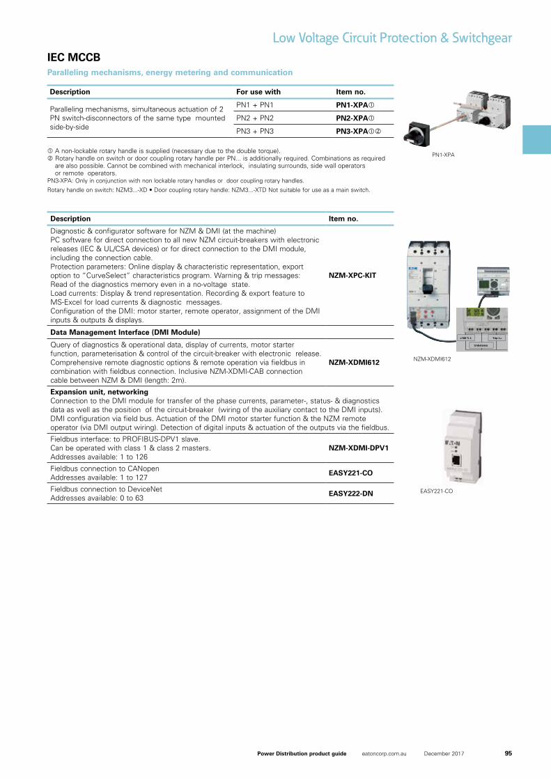
95Power Distribution product guide eatoncorp.com.au December 2017
IEC MCCB
11
Online catalogue Quicklink to www.eaton.com/moellerproducts
NZM06EN
�
The plus-minus slot can be used like the Pozidriv slot to apply a high torque and provides improved centring performance and a lower high loading pressure to an area. Furthermore, it can be used with several tool designs and is particularly suitable for high-maintenance devices.
>100 % Ir Trip I sd
Unbalance
A single tool for all screws
The heads on all screws used in the circuit-breakers – with the exception of the main connection screws – feature a plus-minus pro�le. The advantage is that a fast screw driving machine can be used with the single Posidriv 2 screwdriver tool, or alternatively, a �at-bladed screwdriver can also be used. This applies for all �xing screws, auxil-iary connection terminals, as well as hinged �aps and covers and also all setting buttons.
All messages in detail – the Data Management Interface
It does not matter if the causes for a trip or a warning message with unbalance are required, or if all phase currents are to be displayed directly on-site and corrective actions are to be implemented with a critical load state. The Data Management Interface (DMI) always signals exact details. The relay outputs of the DMI signal up to 6 di�erent messages. All trip causes are available as group signals and I i, Ir, Isd, I2t, and Idn detail signals. The trip cause, phase state, switch setting as well as date and time can be accessed via the 4-line display. Representation of the actual phase currents can be in absolute or relative (% Ir) terms. Warnings with regard to the load status are issued at 70 %, 100 % and 120 % Ir. Thus, the DMI is perfect for direct display on-site or for the integration in higher-level energy management concepts.
)b)a
15
Parallel operation: smart technology
Parallel drives for switches up to 630 A enable simultaneous switching with just a single action – e.g. with main or auxiliary circuits. In this manner the main and auxiliary circuits can be switched simultaneously with process and processing machines.
Interlock with Bowden cable technology
Mechanical interlock components enable the interlocking of two or three switches, equipped with rotary handles (a) or remote operators (b), which can also feature di�erent frame sizes. The Bowden cable technology enables free installation of the switches in di�ering positions. The switches can be installed up to 1 m apart – e.g. in di�erent con-trol panel sections.
Switches in enclosures – certi�ed safety
The transparent enclosures available with protection degrees up to IP 65 provide mechanical protection with impact resistant polycarbonate. The 3- and 4-pole switches are equipped ready for installation with rotary handles. Additional isolated terminations for a 4th or 5th conductor are also available.
Busbar adapter
Busbar adapters featuring space-saving contacts enable installation of many devices in con�ned spaces. They can be used universally on every 60 mm busbar system. The three frame sizes for 160, 250 as well as 630 A can be snapped on.
“ You realise the competence of the people working for Eaton with every solution. All the features you require are implemented.“
Low Voltage Circuit Protection & Switchgear
Paralleling mechanisms, energy metering and communication
Description For use with Item no.
Paralleling mechanisms, simultaneous actuation of 2 PN switch-disconnectors of the same type mounted side-by-side
PN1 + PN1 PN1-XPA
PN2 + PN2 PN2-XPA
PN3 + PN3 PN3-XPA
A non-lockable rotary handle is supplied (necessary due to the double torque). Rotary handle on switch or door coupling rotary handle per PN... is additionally required. Combinations as required
are also possible. Cannot be combined with mechanical interlock, insulating surrounds, side wall operators or remote operators.
PN3-XPA: Only in conjunction with non lockable rotary handles or door coupling rotary handles.
Rotaryhandleonswitch:NZM3...-XD•Doorcouplingrotaryhandle:NZM3...-XTDNotsuitableforuseasamainswitch.
Description Item no.
Diagnostic & configurator software for NZM & DMI (at the machine) PC software for direct connection to all new NZM circuit-breakers with electronic releases (IEC & UL/CSA devices) or for direct connection to the DMI module, including the connection cable. Protection parameters: Online display & characteristic representation, export option to “CurveSelect” characteristics program. Warning & trip messages: Read of the diagnostics memory even in a no-voltage state. Load currents: Display & trend representation. Recording & export feature to MS-Excel for load currents & diagnostic messages. Configuration of the DMI: motor starter, remote operator, assignment of the DMI inputs & outputs & displays.
NZM-XPC-KIT
Data Management Interface (DMI Module)
Query of diagnostics & operational data, display of currents, motor starter function, parameterisation & control of the circuit-breaker with electronic release. Comprehensive remote diagnostic options & remote operation via fieldbus in combination with fieldbus connection. Inclusive NZM-XDMI-CAB connection cable between NZM & DMI (length: 2m).
NZM-XDMI612
Expansion unit, networkingConnection to the DMI module for transfer of the phase currents, parameter-, status- & diagnostics data as well as the position of the circuit-breaker (wiring of the auxiliary contact to the DMI inputs). DMI configuration via field bus. Actuation of the DMI motor starter function & the NZM remote operator (via DMI output wiring). Detection of digital inputs & actuation of the outputs via the fieldbus.
Fieldbus interface: to PROFIBUS-DPV1 slave. Can be operated with class 1 & class 2 masters. Addresses available: 1 to 126
NZM-XDMI-DPV1
Fieldbus connection to CANopen Addresses available: 1 to 127
EASY221-CO
Fieldbus connection to DeviceNet Addresses available: 0 to 63
EASY222-DN
PN1-XPA
NZM-XDMI612
EASY221-CO
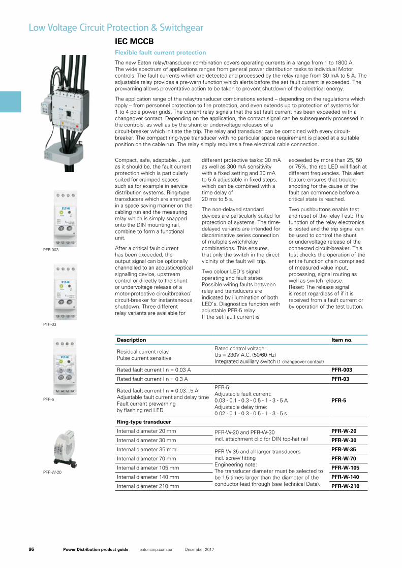
96 Power Distribution product guide eatoncorp.com.au December 2017
IEC MCCB
35
Part no.
PFR-003
PFR-03
PFR-5
PFR-W-20
PFR-W-30
PFR-W-35
PFR-W-70
PFR-W-105
PFR-W-140
PFR-W-210
Two pushbuttons enable test and reset of the relay
Test: The function of the relay electronics is tested and the trip signal can be used to control the shunt or undervoltage release of the connected circuit-breaker. This test checks the operation of the entire function chain comprised of measured value input, processing, signal routing as well as switch release. Reset: The release signal is reset regardless of if it is received from a fault current or by operation of the test button.
Compact, safe, adaptable ...
... just as it should be, the fault current protection which is particularly suited for cramped spaces such as for example in service distribution systems. Ring-type transducers which are arranged in a space saving manner on the cabling run and the measuring relay which is simply snapped onto the DIN mounting rail, combine to form a functional unit. After a critical fault current has been exceeded, the output signal can be optionally channelled to an acoustic/optical signalling device, upstream control or directly to the shunt or undervoltage release of a motor-protective circuit-breaker/circuit-breaker for instantaneous shutdown. Three di�erent relay variants are available for di�erent protective tasks: 30 mA as well as 300 mA sensitivity with a �xed setting and 30 mA to 5 A adjustable in �xed steps, which can be combined with a time delay of 20 ms to 5 s. The non-delayed standard devices are particularly suited for protection of systems. The time-delayed variants are intended for discriminative series connection of multiple switch/relay combinations. This ensures, that only the switch in the direct vicinity of the fault will trip.
Two colour LED’s signal operating and fault states
Possible wiring faults between relay and transducers are indicated by illumination of both LED’s. Diagnostics function with adjustable PFR-5 relay: If the set fault current is exceeded by more than 25, 50 or 75%, the red LED will �ash at di�erent frequencies. This alert feature ensures that trouble-shooting for the cause of the fault can commence before a critical state is reached.
Residual current relay Pulse current sensitive
Ring-type transducer
Rated control voltage: Us = 230V A.C. (50/60 Hz) Integrated auxiliary switch (1 changeover contact)
Rated fault current I� n = 0.03 A
Rated fault current I� n = 0.3 A
Rated fault current I� n = 0.03...5 A Adjustable fault current and delay time
Fault current prewarning by �ashing red LED
Internal diameter 20 mm
Internal diameter 30 mm
Internal diameter 35 mm
Internal diameter 70 mm
Internal diameter 105 mm
Internal diameter 140 mm
Internal diameter 210 mm
PFR-5: Adjustable fault current: 0.03 - 0.1 - 0.3 - 0.5 - 1 - 3 - 5 A
Adjustable delay time:0.02 - 0.1 - 0.3 - 0.5 - 1 - 3 - 5 s
PFR-W-20 and PFR-W-30 incl. attachment clip for DIN top-hat rail
PFR-W-35 and all larger transducers incl. screw �tting
Engineering note:The transducer diameter must be selected to be 1.5 times larger than the diameter of the conductor lead through (see Technical Data).
Residual current relay with ring-type transducer
Low Voltage Circuit Protection & Switchgear
The new Eaton relay/transducer combination covers operating currents in a range from 1 to 1800 A. The wide spectrum of applications ranges from general power distribution tasks to individual Motor controls. The fault currents which are detected and processed by the relay range from 30 mA to 5 A. The adjustable relay provides a pre-warn function which alerts before the set fault current is exceeded. The prewarning allows preventative action to be taken to prevent shutdown of the electrical energy.
The application range of the relay/transducer combinations extend – depending on the regulations which apply – from personnel protection to fire protection, and even extends up to protection of systems for 1 to 4 pole power grids. The current relay signals that the set fault current has been exceeded with a changeover contact. Depending on the application, the contact signal can be subsequently processed in the controls, as well as by the shunt or undervoltage releases of a circuit-breaker which initiate the trip. The relay and transducer can be combined with every circuit-breaker. The compact ring-type transducer with no particular space requirement is placed at a suitable position on the cable run. The relay simply requires a free electrical cable connection.
Flexible fault current protection
Compact, safe, adaptable... just as it should be, the fault current protection which is particularly suited for cramped spaces such as for example in service distribution systems. Ring-type transducers which are arranged in a space saving manner on the cabling run and the measuring relay which is simply snapped onto the DIN mounting rail, combine to form a functional unit.
After a critical fault current has been exceeded, the output signal can be optionally channelled to an acoustic/optical signalling device, upstream control or directly to the shunt or undervoltage release of a motor-protective circuitbreaker/circuit-breaker for instantaneous shutdown. Three different relay variants are available for
different protective tasks: 30 mA as well as 300 mA sensitivity with a fixed setting and 30 mA to 5 A adjustable in fixed steps, which can be combined with a time delay of 20 ms to 5 s.
The non-delayed standard devices are particularly suited for protection of systems. The time-delayed variants are intended for discriminative series connection of multiple switch/relay combinations. This ensures, that only the switch in the direct vicinity of the fault will trip.
Two colour LED’s signal operating and fault states Possible wiring faults between relay and transducers are indicated by illumination of both LED’s. Diagnostics function with adjustable PFR-5 relay: If the set fault current is
exceeded by more than 25, 50 or 75%, the red LED will flash at different frequencies. This alert feature ensures that trouble-shooting for the cause of the fault can commence before a critical state is reached.
Two pushbuttons enable test and reset of the relay Test: The function of the relay electronics is tested and the trip signal can be used to control the shunt or undervoltage release of the connected circuit-breaker. This test checks the operation of the entire function chain comprised of measured value input, processing, signal routing as well as switch release. Reset: The release signal is reset regardless of if it is received from a fault current or by operation of the test button.
Description Item no.
Residual current relay Pulse current sensitive
Rated control voltage:Us = 230V A.C. (50/60 Hz)Integrated auxiliary switch (1 changeover contact)
Rated fault current I n = 0.03 A PFR-003
Rated fault current I n = 0.3 A PFR-03
Rated fault current I n = 0.03...5 AAdjustable fault current and delay timeFault current prewarningby flashing red LED
PFR-5:Adjustable fault current:0.03 - 0.1 - 0.3 - 0.5 - 1 - 3 - 5 AAdjustable delay time:0.02 - 0.1 - 0.3 - 0.5 - 1 - 3 - 5 s
PFR-5
Ring-type transducer
Internal diameter 20 mm PFR-W-20 and PFR-W-30incl. attachment clip for DIN top-hat rail
PFR-W-20
Internal diameter 30 mm PFR-W-30
Internal diameter 35 mm PFR-W-35 and all larger transducersincl.screwfittingEngineering note:The transducer diameter must be selected tobe 1.5 times larger than the diameter of theconductor lead through (see Technical Data).
PFR-W-35
Internal diameter 70 mm PFR-W-70
Internal diameter 105 mm PFR-W-105
Internal diameter 140 mm PFR-W-140
Internal diameter 210 mm PFR-W-210
PFR-5
PFR-03
PFR-003
PFR-W-20
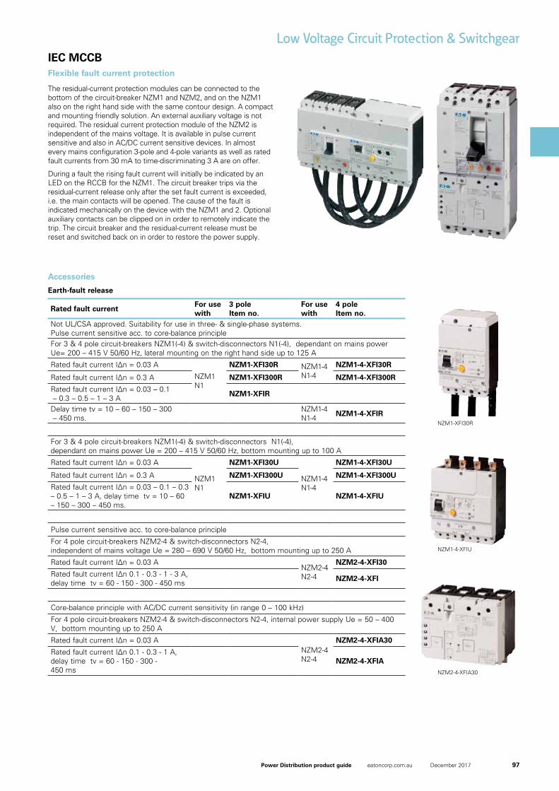
97Power Distribution product guide eatoncorp.com.au December 2017
IEC MCCB
32
The residual-current protection modules can be connected to the bottom of the circuit-breaker NZM1 and NZM2, and on the NZM1 also on the right hand side with the same contour design. A compact and mounting-friendly solution. An external auxiliary voltage is not required. The residual-current protection module of the NZM2 is independent of the mains voltage and can thus be used for personnel protection in Germany. It is available in pulse current sensitive and also in AC/DC current sensitive devices. In almost every mains con�guration 3-pole and 4-pole variants as well as rated fault currents from 30 mA to time-discrimi-nating 3 A are on o�er. During a fault the rising fault current will initially be indicated by an LED on the RCCB for the NZM1. The circuit-breaker trips via the residual-current release only after the set fault current is exceeded, i.e. the main contacts will be opened. The cause of the fault is indicated mechanically on the device with the NZM1 and 2. Optional auxiliary contacts can be clipped on in order to remotely indicate the trip. The circuit-breaker and the residual-current release must be reset and switched back on in order to restore the power supply.
Fault current trip 3-pole 4-pole
detaRnoisreVuninterrupted current
Rated fault current delay timePart no. Part no.
Pulse current sensitive
Mounted at sideMounted at bottomMounted at sideMounted at bottomMounted at side
Mounted at bottomMounted at bottom
AC/DC sensitive
Mounted at bottom
max 160Amax 100Amax 160Amax 100Amax 160A
max 100Amax 250Amax 250A
max 250Amax 250A
I� n = 0.03 A
I� n = 0.3 A
I� n = 0.03 - 0.1 - 0.3 - 0.5 - 1 - 3 Atv = 10 - 60 - 150 - 300 - 450 ms
I� n = 0.03 AI� n = 0.1 - 0.3 - 1 - 3 Atv = 60 - 150 - 300 - 450 ms
I� n = 0.03 AI� n = 0.1 - 0.3 - 1 Atv = 60 - 150 - 300 - 450 ms
NZM1-XFI30RNZM1-XFI30UNZM1-XFI300RNZM1-XFI300UNZM1-XFIR
NZM1-XFIU--
--
NZM1-4-XFI30RNZM1-4-XFI30UNZM1-4-XFI300RNZM1-4-XFI300UNZM1-4-XFIR
NZM1-4-XFIUNZM2-4-XFI30NZM2-4-XFI
NZM2-4-XFIA30NZM2-4-XFIA
Residual-current protection module up to 250 A rated current
Low Voltage Circuit Protection & Switchgear
Flexible fault current protection
The residual-current protection modules can be connected to the bottom of the circuit-breaker NZM1 and NZM2, and on the NZM1 also on the right hand side with the same contour design. A compact and mounting friendly solution. An external auxiliary voltage is not required. The residual current protection module of the NZM2 is independent of the mains voltage. It is available in pulse current sensitive and also in AC/DC current sensitive devices. In almost every mains configuration 3-pole and 4-pole variants as well as rated fault currents from 30 mA to time-discriminating 3 A are on offer.
During a fault the rising fault current will initially be indicated by an LED on the RCCB for the NZM1. The circuit breaker trips via the residual-current release only after the set fault current is exceeded, i.e. the main contacts will be opened. The cause of the fault is indicated mechanically on the device with the NZM1 and 2. Optional auxiliary contacts can be clipped on in order to remotely indicate the trip. The circuit breaker and the residual-current release must be reset and switched back on in order to restore the power supply.
Accessories
Earth-fault release
Rated fault currentFor use with
3 pole Item no.
For use with
4 pole Item no.
Not UL/CSA approved. Suitability for use in three- & single-phase systems. Pulse current sensitive acc. to core-balance principle For 3 & 4 pole circuit-breakers NZM1(-4) & switch-disconnectors N1(-4), dependant on mains power Ue= 200 – 415 V 50/60 Hz, lateral mounting on the right hand side up to 125 A
RatedfaultcurrentI∆n=0.03A
NZM1 N1
NZM1-XFI30R NZM1-4 N1-4
NZM1-4-XFI30R
RatedfaultcurrentI∆n=0.3A NZM1-XFI300R NZM1-4-XFI300R
RatedfaultcurrentI∆n=0.03–0.1 – 0.3 – 0.5 – 1 – 3 A NZM1-XFIR
Delay time tv = 10 – 60 – 150 – 300 – 450 ms.
NZM1-4 N1-4 NZM1-4-XFIR
For 3 & 4 pole circuit-breakers NZM1(-4) & switch-disconnectors N1(-4), dependant on mains power Ue = 200 – 415 V 50/60 Hz, bottom mounting up to 100 A
RatedfaultcurrentI∆n=0.03A
NZM1 N1
NZM1-XFI30U
NZM1-4 N1-4
NZM1-4-XFI30U
RatedfaultcurrentI∆n=0.3A NZM1-XFI300U NZM1-4-XFI300U
RatedfaultcurrentI∆n=0.03–0.1–0.3– 0.5 – 1 – 3 A, delay time tv = 10 – 60 – 150 – 300 – 450 ms.
NZM1-XFIU NZM1-4-XFIU
Pulse current sensitive acc. to core-balance principle
For 4 pole circuit-breakers NZM2-4 & switch-disconnectors N2-4, independent of mains voltage Ue = 280 – 690 V 50/60 Hz, bottom mounting up to 250 A
RatedfaultcurrentI∆n=0.03ANZM2-4 N2-4
NZM2-4-XFI30
RatedfaultcurrentI∆n0.1-0.3-1-3A,delay time tv = 60 - 150 - 300 - 450 ms NZM2-4-XFI
Core-balance principle with AC/DC current sensitivity (in range 0 – 100 kHz)
For 4 pole circuit-breakers NZM2-4 & switch-disconnectors N2-4, internal power supply Ue = 50 – 400 V, bottom mounting up to 250 A
RatedfaultcurrentI∆n=0.03ANZM2-4 N2-4
NZM2-4-XFIA30
RatedfaultcurrentI∆n0.1-0.3-1A, delay time tv = 60 - 150 - 300 - 450 ms
NZM2-4-XFIA
NZM1-XFI30R
NZM1-4-XFIU
NZM2-4-XFIA30
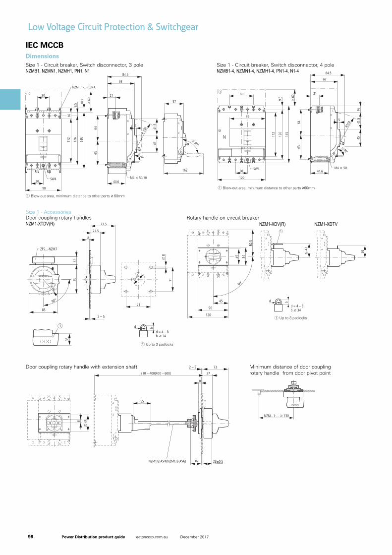
98 Power Distribution product guide eatoncorp.com.au December 2017
Low Voltage Circuit Protection & Switchgear
159
1.16NZM1-4 molded case circuit-breakersDimensions
Size 1: basic devices (NZM1. PN1. N1. NS1)
3 pole
4 pole
Circuit-breakers
Switch-disconnectors
3 pole
NZMB1
NZMC1
NZMN1
NZMH1
PN1
N1
NS1
Circuit-breakers
Switch-disconnectors
4 pole
NZMB1-4
NZMN1-4
NZMH1-4
PN1-4
N1-4
Covers
NZM1(-4)-XKSA
Screw terminals
NZM 1(-4)-XKS
IP2X protection against
contact with a finger
for cover
NZM1(-4)-XIPA
Blow-out area, minimum distance to other parts 60mm
Blow-out area, minimum distance to other parts 60mm
162
1.16 NZM1-4 molded case circuit-breakersDimensions
Size 1: accessories (NZM1-XTVD...)
Door coupling rotary handle with extension shaft
NZM1-XTVD(V)(R)(-NA)
NZM1/2-XV4(6)
NZM1-XTVD(V)(R)-60(-NA) NZM1-XTVD(V)(R)-0(-NA)
Minimum distance of door coupling rotary handle from door pivot point
Special tip
IEC MCCBDimensions
159
1.16NZM1-4 molded case circuit-breakersDimensions
Size 1: basic devices (NZM1. PN1. N1. NS1)
3 pole
4 pole
Circuit-breakers
Switch-disconnectors
3 pole
NZMB1
NZMC1
NZMN1
NZMH1
PN1
N1
NS1
Circuit-breakers
Switch-disconnectors
4 pole
NZMB1-4
NZMN1-4
NZMH1-4
PN1-4
N1-4
Covers
NZM1(-4)-XKSA
Screw terminals
NZM 1(-4)-XKS
IP2X protection against
contact with a finger
for cover
NZM1(-4)-XIPA
Blow-out area, minimum distance to other parts 60mm
Blow-out area, minimum distance to other parts 60mm
Size 1 - Circuit breaker, Switch disconnector, 3 poleNZMB1, NZMN1, NZMH1, PN1, N1
Size 1 - Accessories
161
1.16NZM1-4 molded case circuit-breakersDimensions
Size 1: accessories (NZM1-XDV.... NZM1-XTVD...)
Rotary handle on circuit-breaker
Door coupling rotary handles
NZM1-XTVD(V)(R)(-NA)
Up to 3 padlocks
Up to 3 padlocks
161
1.16NZM1-4 molded case circuit-breakersDimensions
Size 1: accessories (NZM1-XDV.... NZM1-XTVD...)
Rotary handle on circuit-breaker
Door coupling rotary handles
NZM1-XTVD(V)(R)(-NA)
Up to 3 padlocks
Up to 3 padlocks
161
1.16NZM1-4 molded case circuit-breakersDimensions
Size 1: accessories (NZM1-XDV.... NZM1-XTVD...)
Rotary handle on circuit-breaker
Door coupling rotary handles
NZM1-XTVD(V)(R)(-NA)
Up to 3 padlocks
Up to 3 padlocks
161
1.16NZM1-4 molded case circuit-breakersDimensions
Size 1: accessories (NZM1-XDV.... NZM1-XTVD...)
Rotary handle on circuit-breaker
Door coupling rotary handles
NZM1-XTVD(V)(R)(-NA)
Up to 3 padlocks
Up to 3 padlocks
Door coupling rotary handles
Size 1 - Circuit breaker, Switch disconnector, 4 poleNZMB1-4, NZMN1-4, NZMH1-4, PN1-4, N1-4
161
1.16NZM1-4 molded case circuit-breakersDimensions
Size 1: accessories (NZM1-XDV.... NZM1-XTVD...)
Rotary handle on circuit-breaker
Door coupling rotary handles
NZM1-XTVD(V)(R)(-NA)
Up to 3 padlocks
Up to 3 padlocks
161
1.16NZM1-4 molded case circuit-breakersDimensions
Size 1: accessories (NZM1-XDV.... NZM1-XTVD...)
Rotary handle on circuit-breaker
Door coupling rotary handles
NZM1-XTVD(V)(R)(-NA)
Up to 3 padlocks
Up to 3 padlocks
161
1.16NZM1-4 molded case circuit-breakersDimensions
Size 1: accessories (NZM1-XDV.... NZM1-XTVD...)
Rotary handle on circuit-breaker
Door coupling rotary handles
NZM1-XTVD(V)(R)(-NA)
Up to 3 padlocks
Up to 3 padlocks
161
1.16NZM1-4 molded case circuit-breakersDimensions
Size 1: accessories (NZM1-XDV.... NZM1-XTVD...)
Rotary handle on circuit-breaker
Door coupling rotary handles
NZM1-XTVD(V)(R)(-NA)
Up to 3 padlocks
Up to 3 padlocks
Rotary handle on circuit breakerNZM1-XDV(R) NZM1-XDTV
162
1.16 NZM1-4 molded case circuit-breakersDimensions
Size 1: accessories (NZM1-XTVD...)
Door coupling rotary handle with extension shaft
NZM1-XTVD(V)(R)(-NA)
NZM1/2-XV4(6)
NZM1-XTVD(V)(R)-60(-NA) NZM1-XTVD(V)(R)-0(-NA)
Minimum distance of door coupling rotary handle from door pivot point
Special tip
Door coupling rotary handle with extension shaft Minimum distance of door coupling rotary handle from door pivot point
NZM1-XTDV(R)
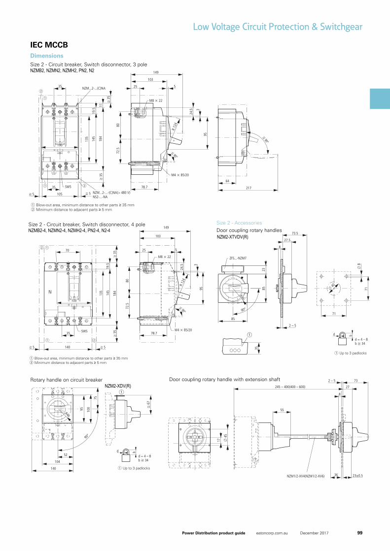
99Power Distribution product guide eatoncorp.com.au December 2017
Low Voltage Circuit Protection & Switchgear
IEC MCCBDimensions Size 2 - Circuit breaker, Switch disconnector, 3 poleNZMB2, NZMN2, NZMH2, PN2, N2
168
1.16 NZM1-4 molded case circuit-breakersDimensions
Size 2: basic devices (NZM2, PN2, N2, NS2)
Circuit-breakers
Switch-disconnectors
3 pole
NZMB2
NZMC2
NZMN2
NZMH2
PN2
N2
NS2
Circuit-breakers
Switch-disconnectors
4 pole
NZMB2-4
NZMN2-4
NZMH2-4
PN2-4
N2-4
Circuit-breakers
3 pole
NZMH2...-XFIA30
Blow-out area, minimum distance to other parts 35 mm
Minimum distance to adjacent parts 5 mm
Blow-out area, minimum distance to other parts 35 mm
Minimum distance to adjacent parts 5 mm
Size 2 - Circuit breaker, Switch disconnector, 4 poleNZMB2-4, NZMN2-4, NZMH2-4, PN2-4, N2-4
168
1.16 NZM1-4 molded case circuit-breakersDimensions
Size 2: basic devices (NZM2, PN2, N2, NS2)
Circuit-breakers
Switch-disconnectors
3 pole
NZMB2
NZMC2
NZMN2
NZMH2
PN2
N2
NS2
Circuit-breakers
Switch-disconnectors
4 pole
NZMB2-4
NZMN2-4
NZMH2-4
PN2-4
N2-4
Circuit-breakers
3 pole
NZMH2...-XFIA30
Blow-out area, minimum distance to other parts 35 mm
Minimum distance to adjacent parts 5 mm
Blow-out area, minimum distance to other parts 35 mm
Minimum distance to adjacent parts 5 mm
Size 2 - Accessories
170
1.16 NZM1-4 molded case circuit-breakersDimensions
Size 2: accessories (NZM2...-XKR.... NZM2-XDV..., NZM2-XDTV...)
Rear terminal bolts
(+)NZM2(-4)-XKR(0)(U)
Rotary handle on circuit-breaker
NZM2-XDV
NZM2-XDVR
NZM2-XDTV
NZM2-XDTV2
Up to 3 padlocks
170
1.16 NZM1-4 molded case circuit-breakersDimensions
Size 2: accessories (NZM2...-XKR.... NZM2-XDV..., NZM2-XDTV...)
Rear terminal bolts
(+)NZM2(-4)-XKR(0)(U)
Rotary handle on circuit-breaker
NZM2-XDV
NZM2-XDVR
NZM2-XDTV
NZM2-XDTV2
Up to 3 padlocks
170
1.16 NZM1-4 molded case circuit-breakersDimensions
Size 2: accessories (NZM2...-XKR.... NZM2-XDV..., NZM2-XDTV...)
Rear terminal bolts
(+)NZM2(-4)-XKR(0)(U)
Rotary handle on circuit-breaker
NZM2-XDV
NZM2-XDVR
NZM2-XDTV
NZM2-XDTV2
Up to 3 padlocks
Rotary handle on circuit breakerNZM2-XDV(R)
168
1.16 NZM1-4 molded case circuit-breakersDimensions
Size 2: basic devices (NZM2, PN2, N2, NS2)
Circuit-breakers
Switch-disconnectors
3 pole
NZMB2
NZMC2
NZMN2
NZMH2
PN2
N2
NS2
Circuit-breakers
Switch-disconnectors
4 pole
NZMB2-4
NZMN2-4
NZMH2-4
PN2-4
N2-4
Circuit-breakers
3 pole
NZMH2...-XFIA30
Blow-out area, minimum distance to other parts 35 mm
Minimum distance to adjacent parts 5 mm
Blow-out area, minimum distance to other parts 35 mm
Minimum distance to adjacent parts 5 mm
171
1.16NZM1-4 molded case circuit-breakersDimensions
Size 2: accessories (NZM2-XTV..., NZM1/2-XV4(6))
Door coupling rotary handles
NZM2-XTVD(V)(R)...
Up to 3 padlocks
Door coupling rotary handle with extension shaft
NZM2-XTVD(V)(R)(-NA)
NZM1/2-XV4(6)
171
1.16NZM1-4 molded case circuit-breakersDimensions
Size 2: accessories (NZM2-XTV..., NZM1/2-XV4(6))
Door coupling rotary handles
NZM2-XTVD(V)(R)...
Up to 3 padlocks
Door coupling rotary handle with extension shaft
NZM2-XTVD(V)(R)(-NA)
NZM1/2-XV4(6)
171
1.16NZM1-4 molded case circuit-breakersDimensions
Size 2: accessories (NZM2-XTV..., NZM1/2-XV4(6))
Door coupling rotary handles
NZM2-XTVD(V)(R)...
Up to 3 padlocks
Door coupling rotary handle with extension shaft
NZM2-XTVD(V)(R)(-NA)
NZM1/2-XV4(6)
171
1.16NZM1-4 molded case circuit-breakersDimensions
Size 2: accessories (NZM2-XTV..., NZM1/2-XV4(6))
Door coupling rotary handles
NZM2-XTVD(V)(R)...
Up to 3 padlocks
Door coupling rotary handle with extension shaft
NZM2-XTVD(V)(R)(-NA)
NZM1/2-XV4(6)
Door coupling rotary handles
171
1.16NZM1-4 molded case circuit-breakersDimensions
Size 2: accessories (NZM2-XTV..., NZM1/2-XV4(6))
Door coupling rotary handles
NZM2-XTVD(V)(R)...
Up to 3 padlocks
Door coupling rotary handle with extension shaft
NZM2-XTVD(V)(R)(-NA)
NZM1/2-XV4(6)
171
1.16NZM1-4 molded case circuit-breakersDimensions
Size 2: accessories (NZM2-XTV..., NZM1/2-XV4(6))
Door coupling rotary handles
NZM2-XTVD(V)(R)...
Up to 3 padlocks
Door coupling rotary handle with extension shaft
NZM2-XTVD(V)(R)(-NA)
NZM1/2-XV4(6)
Door coupling rotary handle with extension shaft
NZM2-XTVDV(R)
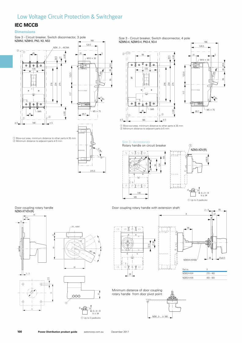
100 Power Distribution product guide eatoncorp.com.au December 2017
Low Voltage Circuit Protection & Switchgear
180
1.16 NZM1-4 molded case circuit-breakersDimensions
Size 3: basic devices (NZM3, PN3, N3, NS3)
Circuit-breakers
Switch-disconnectors
3 pole
NZMN3
NZMH3
PN3
N3
NS3
Circuit-breakers
Switch-disconnectors
4 pole
NZMN3-4
NZMH3-4
PN3-4
N3-4
Blow-out area, minimum distance to other parts 35 mm
Minimum distance to adjacent parts 5 mm
Blow-out area, minimum distance to other parts 35 mm
Minimum distance to adjacent parts 5 mm
Size 3 - Circuit breaker, Switch disconnector, 4 poleNZMN3-4, NZMH3-4, PN3-4, N3-4
IEC MCCBDimensions Size 3 - Circuit breaker, Switch disconnector, 3 poleNZMN3, NZMH3, PN3, N3, NS3
180
1.16 NZM1-4 molded case circuit-breakersDimensions
Size 3: basic devices (NZM3, PN3, N3, NS3)
Circuit-breakers
Switch-disconnectors
3 pole
NZMN3
NZMH3
PN3
N3
NS3
Circuit-breakers
Switch-disconnectors
4 pole
NZMN3-4
NZMH3-4
PN3-4
N3-4
Blow-out area, minimum distance to other parts 35 mm
Minimum distance to adjacent parts 5 mm
Blow-out area, minimum distance to other parts 35 mm
Minimum distance to adjacent parts 5 mm
184
1.16 NZM1-4 molded case circuit-breakersDimensions
Size 3: accessories (NZM3-XDV..., NZM3-XTVD...)
Rotary handle on circuit-breaker
Door coupling rotary handles
NZM3-XTVD(V)(R)...
Up to 3 padlocks
Up to 3 padlocks
NZM3-XDV
NZM3-XDVR
184
1.16 NZM1-4 molded case circuit-breakersDimensions
Size 3: accessories (NZM3-XDV..., NZM3-XTVD...)
Rotary handle on circuit-breaker
Door coupling rotary handles
NZM3-XTVD(V)(R)...
Up to 3 padlocks
Up to 3 padlocks
NZM3-XDV
NZM3-XDVR
184
1.16 NZM1-4 molded case circuit-breakersDimensions
Size 3: accessories (NZM3-XDV..., NZM3-XTVD...)
Rotary handle on circuit-breaker
Door coupling rotary handles
NZM3-XTVD(V)(R)...
Up to 3 padlocks
Up to 3 padlocks
NZM3-XDV
NZM3-XDVR
184
1.16 NZM1-4 molded case circuit-breakersDimensions
Size 3: accessories (NZM3-XDV..., NZM3-XTVD...)
Rotary handle on circuit-breaker
Door coupling rotary handles
NZM3-XTVD(V)(R)...
Up to 3 padlocks
Up to 3 padlocks
NZM3-XDV
NZM3-XDVR
NZM3-XTVDV(R)Door coupling rotary handle
184
1.16 NZM1-4 molded case circuit-breakersDimensions
Size 3: accessories (NZM3-XDV..., NZM3-XTVD...)
Rotary handle on circuit-breaker
Door coupling rotary handles
NZM3-XTVD(V)(R)...
Up to 3 padlocks
Up to 3 padlocks
NZM3-XDV
NZM3-XDVR
Size 3 - AccessoriesRotary handle on circuit breaker
184
1.16 NZM1-4 molded case circuit-breakersDimensions
Size 3: accessories (NZM3-XDV..., NZM3-XTVD...)
Rotary handle on circuit-breaker
Door coupling rotary handles
NZM3-XTVD(V)(R)...
Up to 3 padlocks
Up to 3 padlocks
NZM3-XDV
NZM3-XDVR
184
1.16 NZM1-4 molded case circuit-breakersDimensions
Size 3: accessories (NZM3-XDV..., NZM3-XTVD...)
Rotary handle on circuit-breaker
Door coupling rotary handles
NZM3-XTVD(V)(R)...
Up to 3 padlocks
Up to 3 padlocks
NZM3-XDV
NZM3-XDVR
NZM3-XDV(R)
Door coupling rotary handle with extension shaft
185
1.16NZM1-4 molded case circuit-breakersDimensions
Size 3: accessories (NZM3-XTVD...)
Door coupling rotary handle with extension shaft
NZM3-XTVD(V)(R)(-NA)
NZM3/4-XV4(6)
NZM3-XTVD(V)(R)-60(-NA)
Part no. X
NZM3/4-XV4
NZM3/4-XV6
270 – 400
400 – 600
Minimum distance of door coupling rotary handle from door pivot point
NZM3-XTVD(V)(R)-0(-NA)
Special tip
Minimum distance of door coupling rotary handle from door pivot point
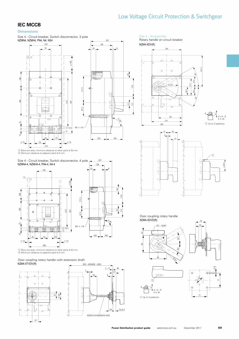
101Power Distribution product guide eatoncorp.com.au December 2017
Low Voltage Circuit Protection & SwitchgearIEC MCCBDimensions Size 4 - Circuit breaker, Switch disconnector, 3 poleNZMN4, NZMH4, PN4, N4, NS4
190
1.16 NZM1-4 molded case circuit-breakersDimensions
Size 4: basic devices (NZM4. N4. NS4)
Circuit-breakers
Switch-disconnectors
3 pole
NZMN4
NZMH4
N4
NS4
Circuit-breakers
3 pole
NZMN4-VE2000
NZMH4-VE2000
Blow-out area, minimum distance to other parts 35 mm
Minimum distance to adjacent parts 5 mm
190
1.16 NZM1-4 molded case circuit-breakersDimensions
Size 4: basic devices (NZM4. N4. NS4)
Circuit-breakers
Switch-disconnectors
3 pole
NZMN4
NZMH4
N4
NS4
Circuit-breakers
3 pole
NZMN4-VE2000
NZMH4-VE2000
Blow-out area, minimum distance to other parts 35 mm
Minimum distance to adjacent parts 5 mm
190
1.16 NZM1-4 molded case circuit-breakersDimensions
Size 4: basic devices (NZM4. N4. NS4)
Circuit-breakers
Switch-disconnectors
3 pole
NZMN4
NZMH4
N4
NS4
Circuit-breakers
3 pole
NZMN4-VE2000
NZMH4-VE2000
Blow-out area, minimum distance to other parts 35 mm
Minimum distance to adjacent parts 5 mm
Door coupling rotary handleNZM4-XDVD(R)
198
1.16 NZM1-4 molded case circuit-breakersDimensions
Size 4: accessories (NZM4-XDV..., NZM4-XTVD...)
Rotary handle on circuit-breaker
NZM4-XDV(R)
Door coupling rotary handles
NZM4-XTVD(V)(R)...
Up to 3 padlocks
Up to 3 padlocks
198
1.16 NZM1-4 molded case circuit-breakersDimensions
Size 4: accessories (NZM4-XDV..., NZM4-XTVD...)
Rotary handle on circuit-breaker
NZM4-XDV(R)
Door coupling rotary handles
NZM4-XTVD(V)(R)...
Up to 3 padlocks
Up to 3 padlocks
198
1.16 NZM1-4 molded case circuit-breakersDimensions
Size 4: accessories (NZM4-XDV..., NZM4-XTVD...)
Rotary handle on circuit-breaker
NZM4-XDV(R)
Door coupling rotary handles
NZM4-XTVD(V)(R)...
Up to 3 padlocks
Up to 3 padlocks
190
1.16 NZM1-4 molded case circuit-breakersDimensions
Size 4: basic devices (NZM4. N4. NS4)
Circuit-breakers
Switch-disconnectors
3 pole
NZMN4
NZMH4
N4
NS4
Circuit-breakers
3 pole
NZMN4-VE2000
NZMH4-VE2000
Blow-out area, minimum distance to other parts 35 mm
Minimum distance to adjacent parts 5 mm
191
1.16NZM1-4 molded case circuit-breakersDimensions
Size 4: accessories (NZM4, N4, NZM4..XK)
Circuit-breakers
Switch-disconnectors
4 pole
NZMN4-4
NZMH4-4
N4-4
Covers
NZMN4(-4)-XKSA
Tunnel terminal
NZMN 4-4-XKA
Blow-out area, minimum distance to other parts 100 mm
Minimum distance to adjacent parts 15 mm
3 pole
4 pole
Clearance from conductive parts 100 mm up to 690 V; 200 mm up to 1000 V
Size 4 - Circuit breaker, Switch disconnector, 4 poleNZMN4-4, NZMH4-4, PN4-4, N4-4
Size 4 - Accessories
198
1.16 NZM1-4 molded case circuit-breakersDimensions
Size 4: accessories (NZM4-XDV..., NZM4-XTVD...)
Rotary handle on circuit-breaker
NZM4-XDV(R)
Door coupling rotary handles
NZM4-XTVD(V)(R)...
Up to 3 padlocks
Up to 3 padlocks
198
1.16 NZM1-4 molded case circuit-breakersDimensions
Size 4: accessories (NZM4-XDV..., NZM4-XTVD...)
Rotary handle on circuit-breaker
NZM4-XDV(R)
Door coupling rotary handles
NZM4-XTVD(V)(R)...
Up to 3 padlocks
Up to 3 padlocks
198
1.16 NZM1-4 molded case circuit-breakersDimensions
Size 4: accessories (NZM4-XDV..., NZM4-XTVD...)
Rotary handle on circuit-breaker
NZM4-XDV(R)
Door coupling rotary handles
NZM4-XTVD(V)(R)...
Up to 3 padlocks
Up to 3 padlocks
NZM4-XDV(R)Rotary handle on circuit breaker
199
1.16NZM1-4 molded case circuit-breakersDimensions
Size 4: accessories (NZM4-XTVD.... NZM4...-XV. NZM4-XS...)
Door coupling rotary handle with extension shaft
NZM4-XTVD(V)(R)(-NA)
NZM3/4-XV4(6)
NZM4-XTVD(V)(R)-60(-NA)
Minimum distance of door coupling rotary handle from door pivot point
Main switch assembly kit for side wall installation
NZM4-XS(R)-L
NZM4-XS(R)-R
NZM4-XTVD(V)(R)-0(-NA)
Special tip
Door coupling rotary handle with extension shaftNZM4-XTVDV(R)
198
1.16 NZM1-4 molded case circuit-breakersDimensions
Size 4: accessories (NZM4-XDV..., NZM4-XTVD...)
Rotary handle on circuit-breaker
NZM4-XDV(R)
Door coupling rotary handles
NZM4-XTVD(V)(R)...
Up to 3 padlocks
Up to 3 padlocks
Recommended