Lubrication of Rolling BearingsPrinciples
Lubrication methods Lubricant selection and testing
Storage and handling

Foreword
Schaeffler Group The Schaeffler Group with its brands INA and FAG is a leading world-wide supplier of rolling bearings, spherical plain bearings, plain bearings, linear products, accessories specific to bearings and comprehensive maintenance products and services. It has approxi-mately 40 000 catalogue products manufactured as standard, providing an extremely wide portfolio that gives secure coverage of applications from all 60 designated industrial market sectors.
Research and development As a company looking to the future, we are especially active in the field of research and development. The key areas in this respect include not only research into fundamental principles, materials technology, tribology and calculation but also extensive inspection and test methods as well as activities to optimise manufacturing technology. This is oriented towards ensuring the continuous devel-opment, improvement and application of our products in the long term. We carry out research and development on a global basis. Our development centres are linked with each other worldwide and are thus in a position to exchange current information on a very short timescale as well as access and communicate the most recent data. This ensures that a uniform level of knowledge and information is available worldwide.This publication gives a comprehensive overview of the lubrication of rolling bearings.
ST4_9312035211_vorwort.fm Seite 1 Donnerstag, 4. April 2013 10:01 10

2 TPI 176 Schaeffler Technologies
ST4_9312035211_vorwort.fm Seite 2 Donnerstag, 4. April 2013 10:01 10
Schaeffler Technologies TPI 176 3
Page
Lubrication of rolling bearings
Lubricant in the rolling bearing................................................ 4Principles........................................................................... 6
Load carrying capacity and life............................................ 18
Friction and increases in temperature ................................. 37
Lubrication methods............................................................... 52
Lubricant selection ................................................................. 62Special applications........................................................... 88
The supply of lubricant to bearings.......................................... 90Miscibility of lubricants ...................................................... 130
Lubrication systems and monitoring ................................... 133
Contaminants in the lubricant ................................................. 136
Lubricant testing..................................................................... 150Sensory and analytical testing ............................................ 152
Mechanical-dynamic testing ............................................... 157
Storage and handling.............................................................. 168
Dry running and media lubrication, coatings............................ 174Dry running and media lubrication ...................................... 176
Coatings ............................................................................ 180
Industrial Service.................................................................... 188
Lubrication lexicon ................................................................. 196
ST4_2288990603_gesamt_ivz.fm Seite 3 Donnerstag, 4. April 2013 10:01 10
Lubricant in the rolling bearing
#tpi176__en_gb__de.xml_FM8_en_gb.book Seite 4 Donnerstag, 4. April 2013 8:22 08
Schaeffler Technologies TPI 176 5
Page
Lubricant in the rolling bearing
Principles The functions of lubrication....................................................... 6Types of lubrication.............................................................. 6
Lubrication and friction regimes ................................................ 7
The theory of lubrication ........................................................... 8
Viscosity................................................................................... 10The influence of temperature ................................................ 10The influence of pressure ..................................................... 10
The lubricant film in oil lubrication ............................................ 12Minimum lubricant film thickness......................................... 12Nominal viscosity ................................................................. 14Density ................................................................................ 14
The lubricant film in grease lubrication...................................... 15Viscosity ratio ...................................................................... 15Lubricant film thickness ....................................................... 15Grease selection .................................................................. 16
Special lubricants ..................................................................... 17Compound lubrication.......................................................... 17Polymer lubrication .............................................................. 17
Load carrying capacity andrating life
Fatigue theory as a principle ..................................................... 18
Dynamic load carrying capacity and life ..................................... 19
Calculation of the rating life ...................................................... 19Basic rating life .................................................................... 20Adjusted rating life ............................................................... 21Expanded adjusted rating life ............................................... 24Equivalent operating values ................................................. 35
Friction andincreases in temperature
Friction ..................................................................................... 37Heat dissipation................................................................... 37Determining the friction values ............................................. 38Cylindrical roller bearings under axial load............................ 43
Speeds ..................................................................................... 45Thermal reference speed ...................................................... 45Limiting speed ..................................................................... 46Thermally safe operating speed ............................................ 46
Operating temperature.............................................................. 50
ST4_2291340683_ivz.fm Seite 5 Donnerstag, 4. April 2013 10:02 10
6 TPI 176 Schaeffler Technologies
Principles
The functions of lubrication The main function of the lubrication of rolling bearings is to prevent or reduce contact between rolling and sliding surfaces. As a result, friction and wear are kept to a low level.
Types of lubrication A distinction is made between physical and chemical lubrication.
Physical lubrication Lubricant is conveyed into the contact areas of rolling bearings and adheres to the surfaces of parts rolling against each other. The lubricant thus separates the contact surfaces and prevents metal-to-metal contact.
Chemical lubrication If a lubricant film is not formed that can fully support loads, some areas of the surfaces are not separated by the lubricant film. Operation with low levels of wear is possible even in such cases if tribomechanical reaction layers are formed between the additives in the lubricant and the rolling element or bearing ring.Lubricant can be supported not only by additive reactions but also by the thickener in the grease and solid lubricants that are added to the oil or grease. In special cases, it is possible to lubricate rolling bearings with solid substances only.
Rolling and sliding motion On the contact surfaces of rolling bearings, not only rolling motion but also sliding motion occurs and this is dependent on the bearing type. This sliding motion is caused by elastic deformations of the parts rolling against each other, the curved geometry of the rolling surfaces and the kinematics of certain bearing types, such as axial cylindrical roller bearings.In pure sliding motion, the forces and pressures are in general sig-nificantly lower than in the rolling area. This case occurs in the rolling bearing between the cage and rolling elements or between the roller end faces and rib surfaces.
Other functions Other functions of the lubricant are as follows:■ anti-corrosion protection■ heat dissipation from the bearing
(in the case of oil lubrication)■ flushing out of wear particles and contaminants
(recirculating oil lubrication with filtration of the oil)■ support for the sealing effect of bearing seals
(grease collar, pneumatic oil lubrication).
ST4_2292782859_grundlagen.fm Seite 6 Donnerstag, 4. April 2013 10:02 10
Schaeffler Technologies TPI 176 7
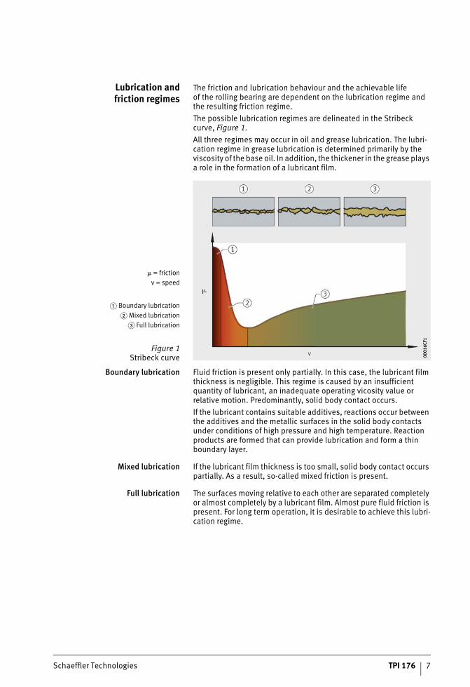
Lubrication andfriction regimes
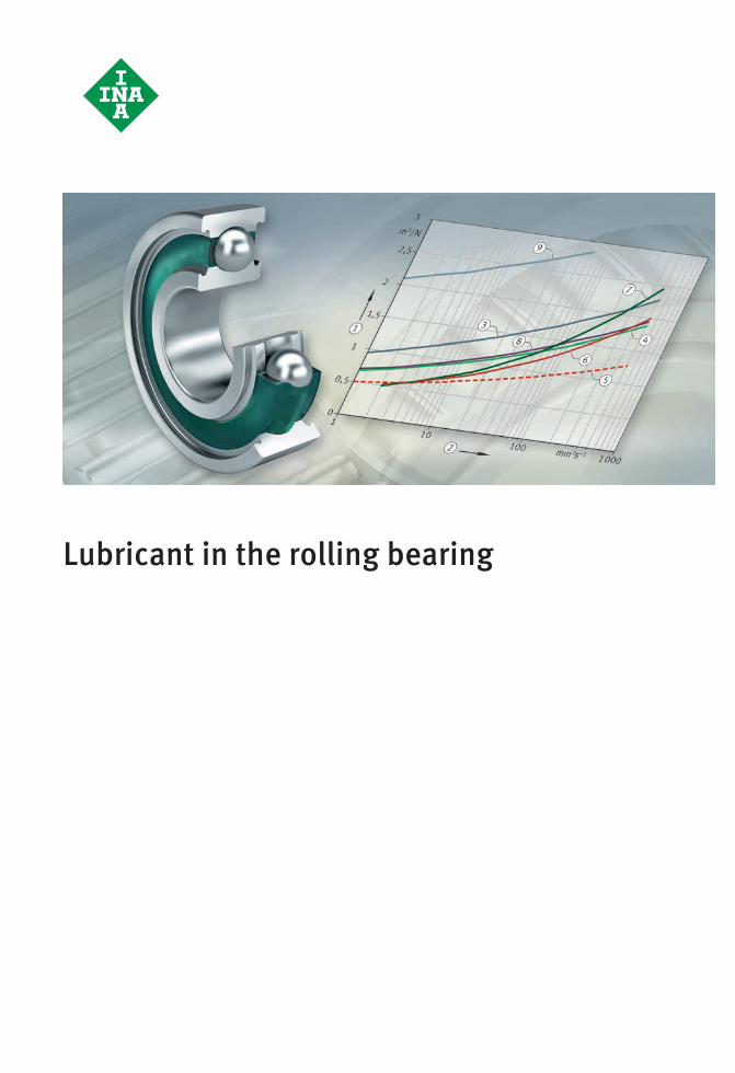
The friction and lubrication behaviour and the achievable life of the rolling bearing are dependent on the lubrication regime and the resulting friction regime.The possible lubrication regimes are delineated in the Stribeck curve, Figure 1.All three regimes may occur in oil and grease lubrication. The lubri-cation regime in grease lubrication is determined primarily by the viscosity of the base oil. In addition, the thickener in the grease plays a role in the formation of a lubricant film.
Boundary lubrication Fluid friction is present only partially. In this case, the lubricant film thickness is negligible. This regime is caused by an insufficient quantity of lubricant, an inadequate operating vicosity value or relative motion. Predominantly, solid body contact occurs.If the lubricant contains suitable additives, reactions occur between the additives and the metallic surfaces in the solid body contacts under conditions of high pressure and high temperature. Reaction products are formed that can provide lubrication and form a thin boundary layer.
Mixed lubrication If the lubricant film thickness is too small, solid body contact occurs partially. As a result, so-called mixed friction is present.
Full lubrication The surfaces moving relative to each other are separated completely or almost completely by a lubricant film. Almost pure fluid friction is present. For long term operation, it is desirable to achieve this lubri-cation regime.
� = frictionv = speed
� Boundary lubrication� Mixed lubrication
� Full lubrication
Figure 1Stribeck curve 00
016C
F100
016C
F1
ST4_2292782859_grundlagen.fm Seite 7 Donnerstag, 4. April 2013 10:02 10
8 TPI 176 Schaeffler Technologies
Principles
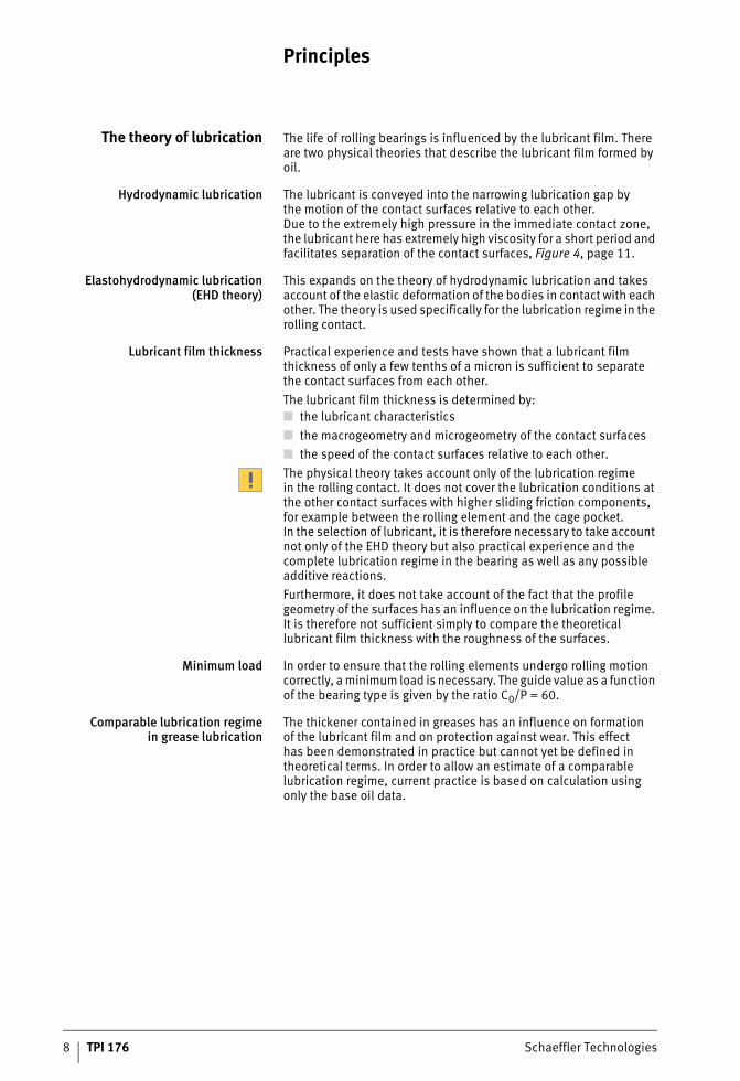
The theory of lubrication The life of rolling bearings is influenced by the lubricant film. There are two physical theories that describe the lubricant film formed by oil.
Hydrodynamic lubrication The lubricant is conveyed into the narrowing lubrication gap by the motion of the contact surfaces relative to each other. Due to the extremely high pressure in the immediate contact zone, the lubricant here has extremely high viscosity for a short period and facilitates separation of the contact surfaces, Figure 4, page 11.
Elastohydrodynamic lubrication(EHD theory)
This expands on the theory of hydrodynamic lubrication and takes account of the elastic deformation of the bodies in contact with each other. The theory is used specifically for the lubrication regime in the rolling contact.
Lubricant film thickness Practical experience and tests have shown that a lubricant film thickness of only a few tenths of a micron is sufficient to separate the contact surfaces from each other.The lubricant film thickness is determined by:■ the lubricant characteristics■ the macrogeometry and microgeometry of the contact surfaces■ the speed of the contact surfaces relative to each other.The physical theory takes account only of the lubrication regime in the rolling contact. It does not cover the lubrication conditions at the other contact surfaces with higher sliding friction components, for example between the rolling element and the cage pocket. In the selection of lubricant, it is therefore necessary to take account not only of the EHD theory but also practical experience and the complete lubrication regime in the bearing as well as any possible additive reactions.Furthermore, it does not take account of the fact that the profile geometry of the surfaces has an influence on the lubrication regime. It is therefore not sufficient simply to compare the theoretical lubricant film thickness with the roughness of the surfaces.
Minimum load In order to ensure that the rolling elements undergo rolling motion correctly, a minimum load is necessary. The guide value as a function of the bearing type is given by the ratio C0/P = 60.
Comparable lubrication regimein grease lubrication
The thickener contained in greases has an influence on formation of the lubricant film and on protection against wear. This effect has been demonstrated in practice but cannot yet be defined in theoretical terms. In order to allow an estimate of a comparable lubrication regime, current practice is based on calculation using only the base oil data.
ST4_2292782859_grundlagen.fm Seite 8 Donnerstag, 4. April 2013 10:02 10
Schaeffler Technologies TPI 176 9
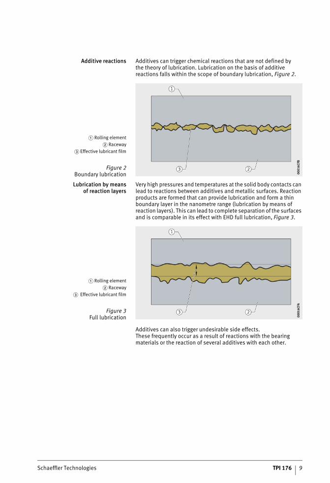
Additive reactions Additives can trigger chemical reactions that are not defined by the theory of lubrication. Lubrication on the basis of additive reactions falls within the scope of boundary lubrication, Figure 2.
Lubrication by meansof reaction layers
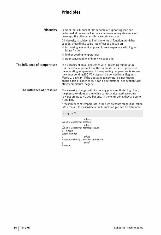
Very high pressures and temperatures at the solid body contacts can lead to reactions between additives and metallic surfaces. Reaction products are formed that can provide lubrication and form a thin boundary layer in the nanometre range (lubrication by means of reaction layers). This can lead to complete separation of the surfaces and is comparable in its effect with EHD full lubrication, Figure 3.
Additives can also trigger undesirable side effects. These frequently occur as a result of reactions with the bearing materials or the reaction of several additives with each other.
� Rolling element� Raceway
� Effective lubricant film
Figure 2Boundary lubrication 00
016C
FB00
016C
FB
� Rolling element� Raceway
� Effective lubricant film
Figure 3Full lubrication 00
016C
FA00
016C
FA
ST4_2292782859_grundlagen.fm Seite 9 Donnerstag, 4. April 2013 10:02 10
10 TPI 176 Schaeffler Technologies
Principles
Viscosity In order that a lubricant film capable of supporting load can be formed at the contact surfaces between rolling elements and raceways, the oil must exhibit a certain viscosity.Oil viscosity is subject to limits in terms of function. At higher speeds, these limits come into effect as a result of:■ increasing mechanical power losses, especially with higher
idling friction■ higher bearing temperatures■ poor conveyability of highly viscous oils.
The influence of temperature The viscosity of an oil decreases with increasing temperature.It is therefore important that the nominal viscosity is present atthe operating temperature. If the operating temperature is known, the corresponding ISO VG class can be derived from diagrams,Figure 2, page 24. If the operating temperature is not knownon the basis of experience, it can be determined, see section Oper-ating temperature, page 50.
The influence of pressure The viscosity changes with increasing pressure. Under high load, the pressure values at the rolling contact calculated according to Hertz are up to 40 000 bar and, in the entry zone, they are up to 7 000 bar.If the influence of temperature in the high pressure range is not taken into account, the viscosity in the lubrication gap can be estimated:
� mPa · sDynamic viscosity at pressure�0 mPa · sDynamic viscosity at normal pressuree = 2,7182 –Euler’s number� m2/NPressure/viscosity coefficient of the fluidp N/m2
Pressure.
ST4_2292782859_grundlagen.fm Seite 10 Donnerstag, 4. April 2013 10:03 10
Schaeffler Technologies TPI 176 11
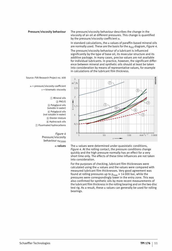
Pressure/viscosity behaviour The pressure/viscosity behaviour describes the change in the viscosity of an oil at different pressures. This change is quantified by the pressure/viscosity coefficient �.In standard calculations, the � values of paraffin-based mineral oils are normally used. These are the basis for the aISO diagram, Figure 4.The pressure/viscosity behaviour of a lubricant is influenced significantly by the type of base oil, its moecular structure and its additive package. In many cases, precise values are not availablefor individual lubricants. In practice, however, the significant differ-ence between mineral and synthetic oils should at least be taken into consideration by means of representative values, for examplein calculations of the lubricant film thickness.
� values The � values were determined under quasistatic conditions, Figure 4. At the rolling contact, the pressure conditions change quickly and the high pressure normally has an effect for a very short time only. The effects of these time influences are not taken into consideration.For the purposes of checking, lubricant film thicknesses were calculated using the � values and the values were compared with measured lubricant film thicknesses. Very good agreement was found at rolling pressures up to pmax = 14 000 bar, while the pressures were correspondingly lower in the entry zone. This was also confirmed for synthetic oils by more recent measurements of the lubricant film thickness in the rolling bearing and on the two disc test rig. As a result, these � values can generally be used for rolling bearings.
Source: FVA Research Project no. 400
� = pressure/viscosity coefficient� = kinematic viscosity
� Mineral oils� PAO/E
� Polyglycol oils(soluble in water)� Polyglycol oils
(not soluble in water)� Diester mixture� Hydrocrack oils
� Fluorinated hydrocarbons
Figure 4Pressure/viscosity
behaviour �P2000
0001
6CFD
0001
6CFD
ST4_2292782859_grundlagen.fm Seite 11 Donnerstag, 4. April 2013 10:03 10
12 TPI 176 Schaeffler Technologies
Principles
The lubricant filmin oil lubrication
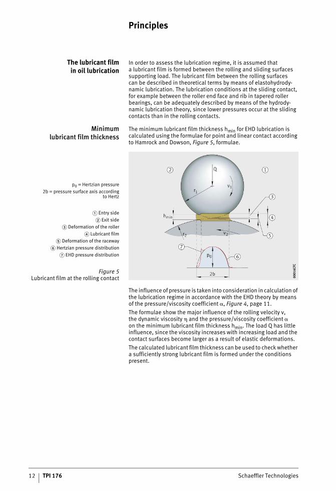
In order to assess the lubrication regime, it is assumed that a lubricant film is formed between the rolling and sliding surfaces supporting load. The lubricant film between the rolling surfaces can be described in theoretical terms by means of elastohydrody-namic lubrication. The lubrication conditions at the sliding contact, for example between the roller end face and rib in tapered roller bearings, can be adequately described by means of the hydrody-namic lubrication theory, since lower pressures occur at the sliding contacts than in the rolling contacts.
Minimumlubricant film thickness
The minimum lubricant film thickness hmin for EHD lubrication is calculated using the formulae for point and linear contact according to Hamrock and Dowson, Figure 5, formulae.
The influence of pressure is taken into consideration in calculation of the lubrication regime in accordance with the EHD theory by means of the pressure/viscosity coefficient �, Figure 4, page 11.The formulae show the major influence of the rolling velocity v, the dynamic viscosity � and the pressure/viscosity coefficient �on the minimum lubricant film thickness hmin. The load Q has little influence, since the viscosity increases with increasing load and the contact surfaces become larger as a result of elastic deformations.The calculated lubricant film thickness can be used to check whether a sufficiently strong lubricant film is formed under the conditions present.
p0 = Hertzian pressure2b = pressure surface axis according
to Hertz
� Entry side� Exit side
� Deformation of the roller� Lubricant film
� Deformation of the raceway� Hertzian pressure distribution
� EHD pressure distribution
Figure 5Lubricant film at the rolling contact 00
016C
FC00
016C
FC
ST4_2292782859_grundlagen.fm Seite 12 Donnerstag, 4. April 2013 10:03 10
Schaeffler Technologies TPI 176 13
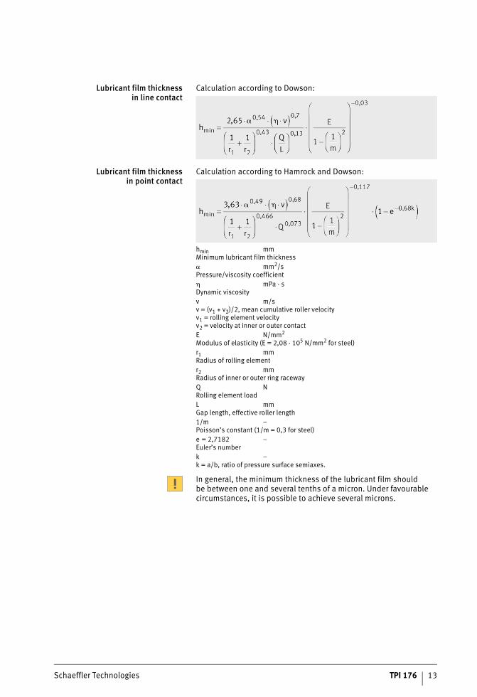
Lubricant film thicknessin line contact
Calculation according to Dowson:
Lubricant film thicknessin point contact
Calculation according to Hamrock and Dowson:
hmin mmMinimum lubricant film thickness� mm2/sPressure/viscosity coefficient� mPa · sDynamic viscosityv m/sv = (v1 + v2)/2, mean cumulative roller velocityv1 = rolling element velocityv2 = velocity at inner or outer contactE N/mm2
Modulus of elasticity (E = 2,08 · 105 N/mm2 for steel)r1 mmRadius of rolling elementr2 mmRadius of inner or outer ring racewayQ NRolling element loadL mmGap length, effective roller length1/m –Poisson’s constant (1/m = 0,3 for steel)e = 2,7182 –Euler’s numberk –k = a/b, ratio of pressure surface semiaxes.
In general, the minimum thickness of the lubricant film should be between one and several tenths of a micron. Under favourable circumstances, it is possible to achieve several microns.
ST4_2292782859_grundlagen.fm Seite 13 Donnerstag, 4. April 2013 10:04 10
14 TPI 176 Schaeffler Technologies
Principles
Nominal viscosity In day-to-day practice, it is too cumbersome to design the nominal oil viscosity through calculation of the lubricant film thickness. Instead, the nominal viscosity is determined by means of the viscosity ratio � = �/�1, see section Viscosity ratio, page 22. The operating viscosity � is the kinematic viscosity of the lubricant at the operating temperature. The reference viscosity �1 is a function of the bearing size and speed. The reference and operating viscosity can be derived from diagrams, Figure 2, page 24.
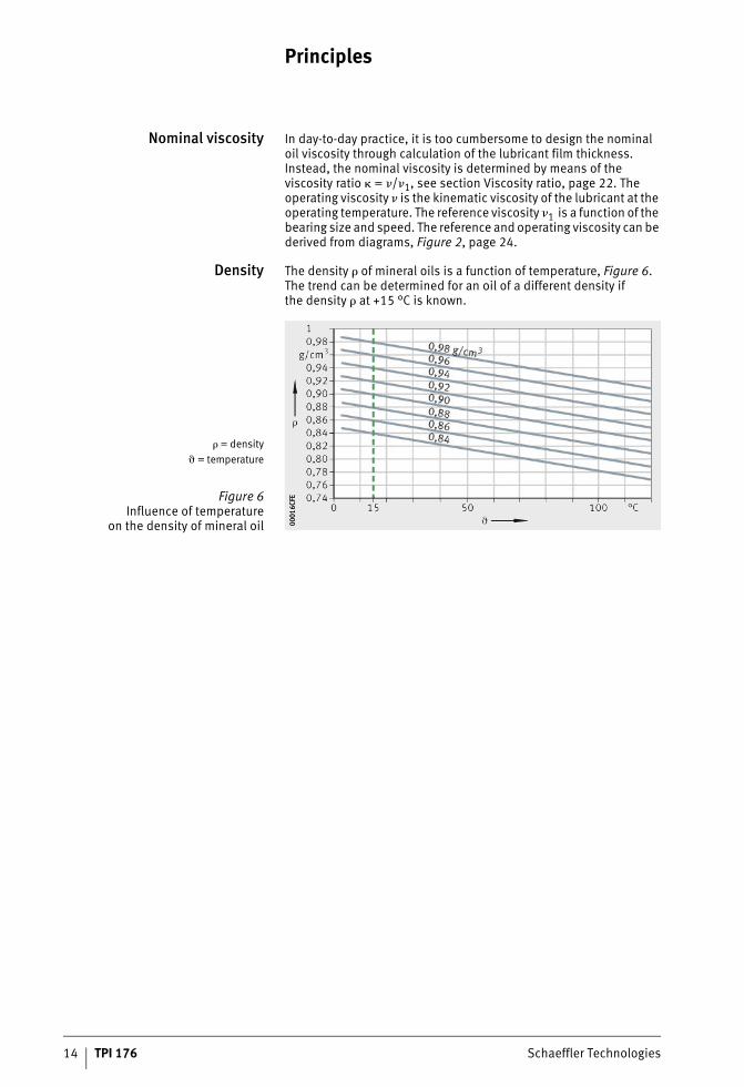
Density The density � of mineral oils is a function of temperature, Figure 6. The trend can be determined for an oil of a different density if the density � at +15 °C is known.
� = density� = temperature
Figure 6Influence of temperature
on the density of mineral oil 0001
6CFE
0001
6CFE
ST4_2292782859_grundlagen.fm Seite 14 Donnerstag, 4. April 2013 10:04 10
Schaeffler Technologies TPI 176 15
The lubricant filmin grease lubrication
In the case of greases, bearing lubrication is performed mainly by the base oil that is released in small quantities over time by the thickener. The principles of the EHD theory also apply to grease lubrication.
Viscosity ratio In order to determine the viscosity ratio � = �/�1 (� = kinematic viscosity of the lubricant at operating temperature, �1 = reference viscosity of the lubricant), the operating viscosity � of the base oil is used, see section Viscosity ratio, page 22.At low � values in particular, the thickener and additives contribute to effective lubrication.
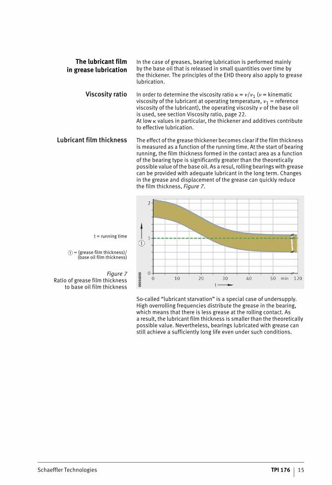
Lubricant film thickness The effect of the grease thickener becomes clear if the film thickness is measured as a function of the running time. At the start of bearing running, the film thickness formed in the contact area as a function of the bearing type is significantly greater than the theoretically possible value of the base oil. As a resul, rolling bearings with grease can be provided with adequate lubricant in the long term. Changes in the grease and displacement of the grease can quickly reduce the film thickness, Figure 7.
So-called “lubricant starvation” is a special case of undersupply. High overrolling frequencies distribute the grease in the bearing, which means that there is less grease at the rolling contact. As a result, the lubricant film thickness is smaller than the theoretically possible value. Nevertheless, bearings lubricated with grease can still achieve a sufficiently long life even under such conditions.
t = running time
� = (grease film thickness)/(base oil film thickness)
Figure 7Ratio of grease film thickness
to base oil film thickness 0001
6D00
0001
6D00
ST4_2292782859_grundlagen.fm Seite 15 Donnerstag, 4. April 2013 10:05 10
16 TPI 176 Schaeffler Technologies
Principles
Grease selection Correct grease lubrication is particularly important in the case of bearings with high proportions of sliding motion and bearings sub-jected to heavy loads. Under high load, the lubrication capability of the thickener and the additive package are of particular importance.In grease lubrication, the amount of lubricant playing an active role in the lubrication process is very small. Grease of normal consistency is largely displaced from the rolling contact and is deposited laterally or exits the bearing arrangement through the seals. The grease remaining on the raceway surfaces and laterally in or on the bearing continuously releases the nominal small quantity of oil and, in some cases, thickener as well for lubrication of the functional surfaces. The effective lubricant quantity between the rolling contact surfaces is sufficient for lubrication under moderate load over an extended period.
Solid lubricants Solid lubricants such as graphite and molybdenum disulphide, which are applied as a thin layer to the functional surfaces, can pre-vent metal-to-metal contact. However, a layer of this type continues to adhere for an extended period only at low circumferential speeds and low pressures. The lubrication of solid body contacts can also be improved by solid lubricants in oils or greases.
Thickeners Thickeners and agents in the grease support lubrication through the formation of boundary layers, with the result that no reduction in life is anticipated. In order to achieve long lubrication intervals, it is advisable that the grease should release precisely the amount of oil that is required for lubrication of the bearing. The release of oil can thus continue over a long period. Greases with a highly viscous base oil have a reduced oil release rate. If these are used, a good lubrication regime can only be achieved if the bearing and housing are filled to a large extent or if relubrication is carried out at short intervals. Certain types of thickener additionally have a the effect of forming boundary layers during operation in the mixed friction range.The release of oil is dependent on:■ the thickener (type, quantity and consistency)■ the additives■ the type of base oil■ the viscosity of the base oil■ the size of the surface releasing oil■ the temperature■ the mechanical strain on the grease.
ST4_2292782859_grundlagen.fm Seite 16 Donnerstag, 4. April 2013 10:05 10
Schaeffler Technologies TPI 176 17
Special lubricants As a supplement to pure oil or grease lubrication, lubrication using special lubricants may be advisable in special applications.
Compound lubrication Solid lubricant compounds that are applied as a thin layer to the functional surfaces can prevent metal-to-metal contact. They comprise a combination of solid lubricants such as molyb-denum disulphide, graphite or PTFE and a binder with good high temperature stability. The bearings are filled with the paste-like compound and this is then hardened by the effect of heat. During operation, the compound rotates with the cage. However, a layer of this type continues to adhere for an extended period only at low circumferential speeds and low pressures.Compound lubrication is a transfer type lubrication, which means that there is ongoing erosion of the hardened compound which is then deposited on the balls and raceway surfaces. Tests have shown that there is a steep reduction in the life of such bearings with increasing speed. In contrast to oil or grease lubrication, the influ-ence of load or temperature is less pronounced.Compound lubrication is used, for example, in the high temperature range � +250 °C, for example in kiln car bearing arrangements or in areas with strong chemical or physical influences such as vacuum.
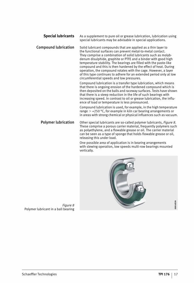
Polymer lubrication Other special lubricants are so-called polymer lubricants, Figure 8. These comprise a porous carrier material, frequently polymers such as polyethylene, and a flowable grease or oil. The carrier material can be seen as a type of sponge that holds flowable grease or oil, releasing this under load.One possible area of application is in bearing arrangements with slewing operation, low speeds multi-row bearings mounted vertically.
Figure 8Polymer lubricant in a ball bearing 00
016D
2A00
016D
2A
ST4_2292782859_grundlagen.fm Seite 17 Donnerstag, 4. April 2013 10:05 10
18 TPI 176 Schaeffler Technologies
Load carrying capacity and rating life
The Schaeffler Group introduced the “Expanded calculation of the adjusted rating life” in 1997. This method was standardised for the first time in DIN ISO 281 Appendix 1 and has been a constituent part of the international standard ISO 281 since 2007.As part of the international standardisation work, the life adjustment factor aDIN was renamed as aISO but without any change to the calcu-lation method.
Fatigue theory as a principle The basis of the rating life calculation in accordance with ISO 281 is the fatigue theory developed by Lundberg and Palmgren, which always gives a final rating life.However, modern, high quality bearings can exceed by a consider-able margin the values calculated for the basic rating life under favourable operating conditions. Ioannides and Harris have devel-oped a further model of fatigue in rolling contact that expands on the theory by Lundberg and Palmgren and gives a better description of the performance capability of modern bearings.The method “Expanded calculation of the adjusted rating life” takes account of the following influences:■ the bearing load■ the fatigue limit of the material■ the extent to which the surfaces are separated by the lubricant■ the cleanliness in the lubrication gap■ the additive package in the lubricant■ the internal load distribution and frictional conditions in the
bearing.The influencing factors, particularly those relating to contamination, are very complex. A great deal of experience is required in order to arrive at an accurate assessment. Further advice should therefore be sought from the Schaeffler Group engineering service.The tables and diagrams can give only guide values.Further information is also given in Catalogue HR1, Rolling Bearings.
Dimensioning of rolling bearings The required size of a rolling bearing is dependent on the demands made on its:■ rating life■ load carrying capacity■ operational reliability.
ST4_3394961035_tragfaehigkeit_.fm Seite 18 Donnerstag, 4. April 2013 10:05 10
Schaeffler Technologies TPI 176 19
Dynamicload carrying capacity and
operating life
The dynamic load carrying capacity is described in terms of the basic dynamic load ratings. The basic dynamic load ratings are based on DIN ISO 281.The fatigue behaviour of the material determines the dynamic load carrying capacity of the rolling bearing.The dynamic load carrying capacity is described in terms of the basic dynamic load rating and the basic rating life.The fatigue life is dependent on:■ the load■ the operating speed■ the statistical probability of the first appearance of failure.The basic dynamic load rating C applies to rotating rolling bearings. It is:■ a constant radial load Cr for radial bearings■ a constant, concentrically acting axial load Ca for axial bearings.The basic dynamic load rating C is that load of constant magnitude and direction which a sufficiently large number of apparently identical bearings can endure for a basic rating life of one million revolutions.
Calculation of the rating life The methods for calculating the rating life are:■ the basic rating life L10 and L10h according to ISO 281■ the adjusted rating life Lna according to DIN ISO 281:1990
(no longer a constituent part of ISO 281)■ the expanded adjusted rating life Lnm according to ISO 281.
ST4_3394961035_tragfaehigkeit_.fm Seite 19 Donnerstag, 4. April 2013 10:05 10
20 TPI 176 Schaeffler Technologies
Load carrying capacity and rating life
Basic rating life The basic rating life L10 and L10h is determined as follows:
L10 106 revolutionsThe basic rating life in millions of revolutions is the life reached or exceeded by 90% of a sufficiently large group of apparently identical bearings before the first evidence of material fatigue developsC NBasic dynamic load ratingP NEquivalent dynamic bearing load for radial and axial bearings,see section Equivalent operating values, page 35p –Life exponent; for roller bearings: p = 10/3for ball bearings: p =3L10h hThe basic rating life in operating hours according to the definition for L10n min–1
Operating speed.
Equivalent dynamic bearing load The equivalent dynamic load P is a calculated value. This value is constant in magnitude and direction; it is a radial load for radial bearings and an axial load for axial bearings.A load corresponding to P will give the same rating life as the com-bined load occurring in practice.
P NEquivalent dynamic bearing loadX –Radial factor given in the dimension tables or product descriptionFr NRadial dynamic bearing load Y –Axial factor given in the dimension tables or product descriptionFa NAxial dynamic bearing load.
This calculation cannot be applied to radial needle roller bearings, axial needle roller bearings and axial cylindrical roller bearings. Combined loads are not permissible with these bearings. Equivalent values for non-constant loads or speeds: see section Equivalent operating values, page 35.
ST4_3394961035_tragfaehigkeit_.fm Seite 20 Donnerstag, 4. April 2013 10:05 10
Schaeffler Technologies TPI 176 21
Adjusted rating life The adjusted rating life Lna can be calculated if, in addition to the load and speed, other influences are known such as:■ special material characteristics■ lubrication
or■ if a requisite reliability other than 90% is specified.This calculation method was replaced in ISO 281:2007 by the calcu-lation of the expanded adjusted rating life Lnm.
Lna 106 revolutionsAdjusted rating life for special material characteristics and operating conditions with a requisite reliability of (100 – n) %a1 –Life adjustment factor for a requisite reliability other than 90% In ISO 281:2007, the values for the life adjustment factor a1 were redefined, see tablea2 –Life adjustment factor for special material characteristics For standard rolling bearing steels: a2 = 1a3 –Life adjustment factor for special operating conditions; in particular for the lubri-cation regime, Figure 1, page 22L10 106 revolutionsBasic rating life.
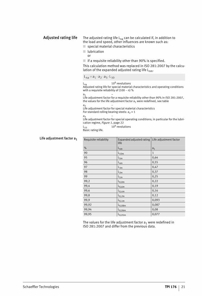
Life adjustment factor a1
The values for the life adjustment factor a1 were redefined in ISO 281:2007 and differ from the previous data.
Requisite reliability Expanded adjusted rating life
Life adjustment factor
% Lnm a1
90 L10m 1
95 L5m 0,64
96 L4m 0,55
97 L3m 0,47
98 L2m 0,37
99 L1m 0,25
99,2 L0,8m 0,22
99,4 L0,6m 0,19
99,6 L0,4m 0,16
99,8 L0,2m 0,12
99,9 L0,1m 0,093
99,92 L0,08m 0,087
99,94 L0,06m 0,08
99,95 L0,05m 0,077
ST4_3394961035_tragfaehigkeit_.fm Seite 21 Donnerstag, 4. April 2013 10:06 10
22 TPI 176 Schaeffler Technologies
Load carrying capacity and rating life
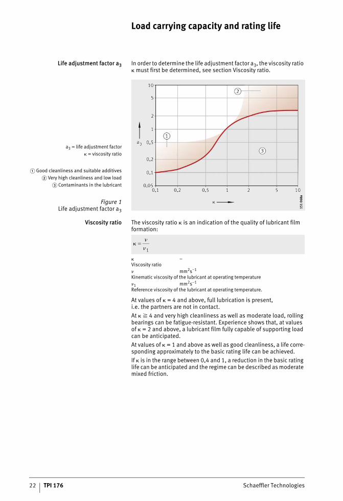
Life adjustment factor a3 In order to determine the life adjustment factor a3, the viscosity ratio � must first be determined, see section Viscosity ratio.
Viscosity ratio The viscosity ratio � is an indication of the quality of lubricant film formation:
� –Viscosity ratio� mm2s–1
Kinematic viscosity of the lubricant at operating temperature�1 mm2s–1
Reference viscosity of the lubricant at operating temperature.
At values of � = 4 and above, full lubrication is present, i.e. the partners are not in contact.At � � 4 and very high cleanliness as well as moderate load, rolling bearings can be fatigue-resistant. Experience shows that, at values of � = 2 and above, a lubricant film fully capable of supporting load can be anticipated.At values of � = 1 and above as well as good cleanliness, a life corre-sponding approximately to the basic rating life can be achieved.If � is in the range between 0,4 and 1, a reduction in the basic rating life can be anticipated and the regime can be described as moderate mixed friction.
a3 = life adjustment factor� = viscosity ratio
� Good cleanliness and suitable additives� Very high cleanliness and low load
� Contaminants in the lubricant
Figure 1Life adjustment factor a3
151
068a
151
068a
ST4_3394961035_tragfaehigkeit_.fm Seite 22 Donnerstag, 4. April 2013 10:06 10
Schaeffler Technologies TPI 176 23
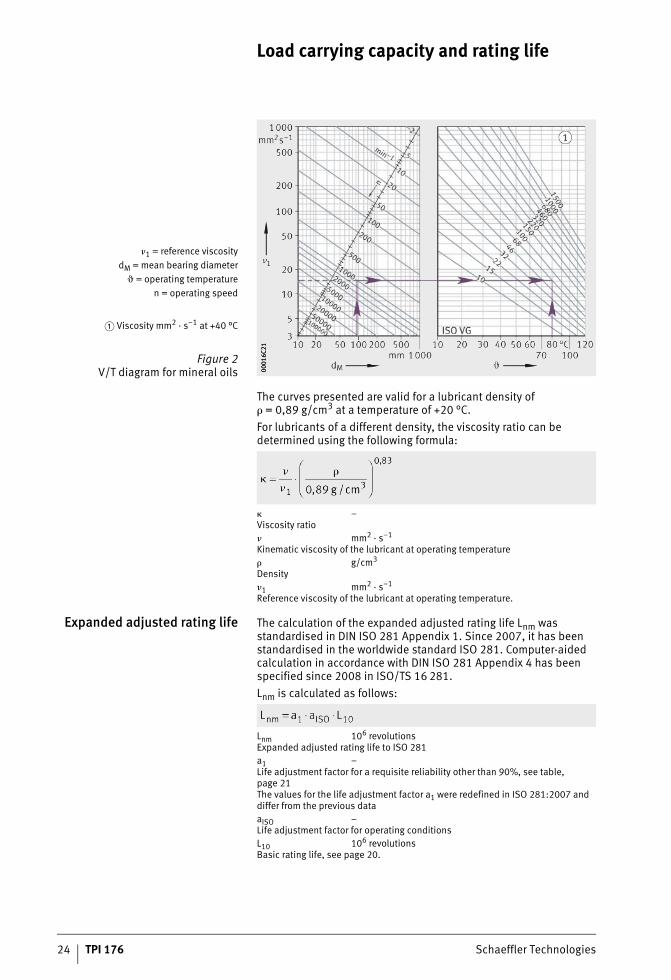
At � � 0,4, mixed friction is present. If undoped lubricants are used in this case, wear must additionally be anticipated. If the lubricant contains suitable anti-wear additives, however, separation in the contact area may also be achieved by the reaction layers formed by the additives. Through this chemical lubrication, it is also possible to achieve low-wear operation, see also section Taking account of EP additives in the lubricant, page 25.The reference viscosity �1 is determined from the mean bearing diameter dM and the operating speed n, Figure 2, page 24.Alternatively, the reference viscosity �1 can also be calculated using the following formulae:
n min–1
Operating speeddM mmMean bearing diameter (d + D)/2.
The nominal viscosity of the oil at +40 °C is determined from the required operating viscosity � and the operating temperature �, Figure 2, page 24. The diagram and the formula � = �/�1 can also be used as an approximation for synthetic oils such as PAO. In this case, the higher viscosity index in comparison with mineral oils is compensated by means of a higher pressure/viscosity coefficient. In the case of greases, the operating viscosity of the base oil is the decisive factor.In the case of heavily loaded bearings with a high proportion of sliding motion, the temperature in the contact area of the rolling elements may be up to 20 K higher than the temperature measured on the stationary ring (without any influence from external heat).
for n � 1000 min–1
for n � 1000 min–1
ST4_3394961035_tragfaehigkeit_.fm Seite 23 Donnerstag, 4. April 2013 10:06 10
24 TPI 176 Schaeffler Technologies
Load carrying capacity and rating life
The curves presented are valid for a lubricant density of � = 0,89 g/cm3 at a temperature of +20 °C.For lubricants of a different density, the viscosity ratio can be determined using the following formula:
� –Viscosity ratio� mm2 · s–1
Kinematic viscosity of the lubricant at operating temperature� g/cm3
Density�1 mm2 · s–1
Reference viscosity of the lubricant at operating temperature.
Expanded adjusted rating life The calculation of the expanded adjusted rating life Lnm was standardised in DIN ISO 281 Appendix 1. Since 2007, it has been standardised in the worldwide standard ISO 281. Computer-aided calculation in accordance with DIN ISO 281 Appendix 4 has been specified since 2008 in ISO/TS 16 281.Lnm is calculated as follows:
Lnm 106 revolutionsExpanded adjusted rating life to ISO 281a1 –Life adjustment factor for a requisite reliability other than 90%, see table, page 21The values for the life adjustment factor a1 were redefined in ISO 281:2007 and differ from the previous dataaISO –Life adjustment factor for operating conditionsL10 106 revolutionsBasic rating life, see page 20.
�1 = reference viscositydM = mean bearing diameter
� = operating temperaturen = operating speed
� Viscosity mm2 · s–1 at +40 °C
Figure 2V/T diagram for mineral oils 00
016C
2100
016C
21
ST4_3394961035_tragfaehigkeit_.fm Seite 24 Donnerstag, 4. April 2013 10:06 10
Schaeffler Technologies TPI 176 25
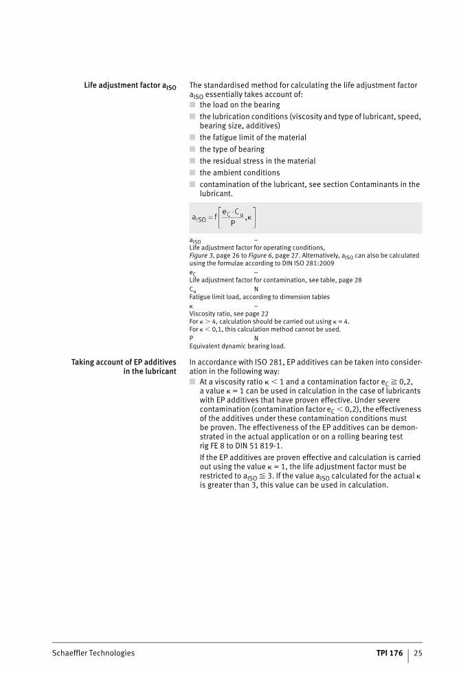
Life adjustment factor aISO The standardised method for calculating the life adjustment factor aISO essentially takes account of:■ the load on the bearing■ the lubrication conditions (viscosity and type of lubricant, speed,
bearing size, additives)■ the fatigue limit of the material■ the type of bearing■ the residual stress in the material■ the ambient conditions■ contamination of the lubricant, see section Contaminants in the
lubricant.
aISO –Life adjustment factor for operating conditions, Figure 3, page 26 to Figure 6, page 27. Alternatively, aISO can also be calculated using the formulae according to DIN ISO 281:2009eC –Life adjustment factor for contamination, see table, page 28Cu NFatigue limit load, according to dimension tables� –Viscosity ratio, see page 22For � � 4, calculation should be carried out using � = 4.For � � 0,1, this calculation method cannot be used.P NEquivalent dynamic bearing load.
Taking account of EP additivesin the lubricant
In accordance with ISO 281, EP additives can be taken into consider-ation in the following way:■ At a viscosity ratio � � 1 and a contamination factor eC � 0,2,
a value � = 1 can be used in calculation in the case of lubricants with EP additives that have proven effective. Under severe contamination (contamination factor eC � 0,2), the effectiveness of the additives under these contamination conditions must be proven. The effectiveness of the EP additives can be demon-strated in the actual application or on a rolling bearing test rig FE 8 to DIN 51 819-1.If the EP additives are proven effective and calculation is carried out using the value � = 1, the life adjustment factor must be restricted to aISO � 3. If the value aISO calculated for the actual � is greater than 3, this value can be used in calculation.
ST4_3394961035_tragfaehigkeit_.fm Seite 25 Donnerstag, 4. April 2013 10:07 10
26 TPI 176 Schaeffler Technologies
Load carrying capacity and rating life
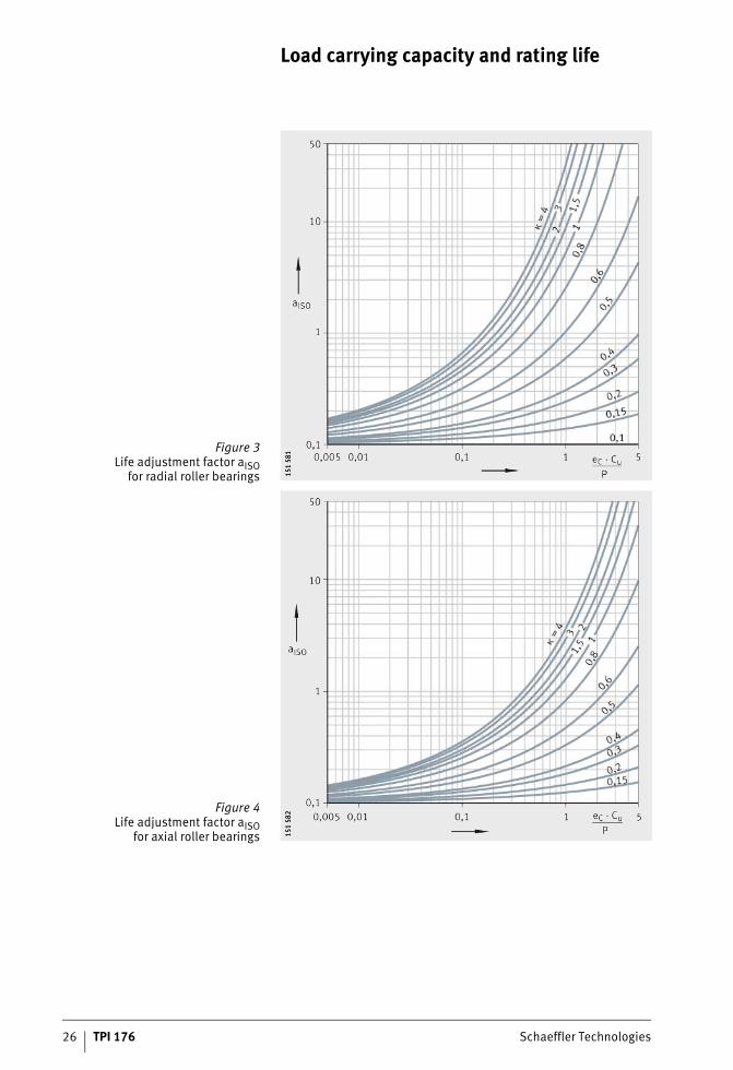
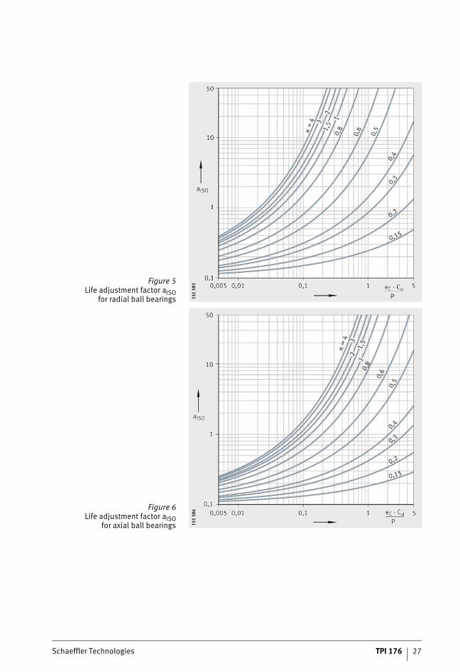
Figure 3Life adjustment factor aISO
for radial roller bearings 151
581
151
581
Figure 4Life adjustment factor aISO
for axial roller bearings 151
582
151
582
ST4_3394961035_tragfaehigkeit_.fm Seite 26 Donnerstag, 4. April 2013 10:07 10
Schaeffler Technologies TPI 176 27
Figure 5Life adjustment factor aISO
for radial ball bearings 151
583
151
583
Figure 6Life adjustment factor aISO
for axial ball bearings 151
584
151
584
ST4_3394961035_tragfaehigkeit_.fm Seite 27 Donnerstag, 4. April 2013 10:08 10
28 TPI 176 Schaeffler Technologies
Load carrying capacity and rating life
Fatigue limit load The fatigue limit load Cu is defined in accordance with ISO 281 as the load at which the most heavily loaded rolling element reaches the fatigue limit.
Life adjustment factorfor contamination
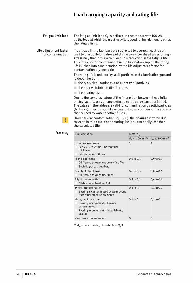
If particles in the lubricant are subjected to overrolling, this can lead to plastic deformations of the raceway. Localised areas of high stress may then occur which lead to a reduction in the fatigue life. This influence of contaminants in the lubrication gap on the rating life is taken into consideration by the life adjustment factor for contamination eC, see table.The rating life is reduced by solid particles in the lubrication gap and is dependent on:■ the type, size, hardness and quantity of particles■ the relative lubricant film thickness■ the bearing size.Due to the complex nature of the interaction between these influ-encing factors, only an approximate guide value can be attained. The values in the tables are valid for contamination by solid particles (factor eC). They do not take account of other contamination such as that caused by water or other fluids.Under severe contamination (eC → 0), the bearings may fail due to wear. In this case, the operating life is substantially less thanthe calculated life.
Factor eC
1) dM = mean bearing diameter (d + D)/2.
Contamination Factor eC
dM � 100 mm1) dM � 100 mm1)
Extreme cleanliness■ Particle size within lubricant film
thickness■ Laboratory conditions
1 1
High cleanliness■ Oil filtered through extremely fine filter■ Sealed, greased bearings
0,8 to 0,6 0,9 to 0,8
Standard cleanliness■ Oil filtered through fine filter
0,6 to 0,5 0,8 to 0,6
Slight contamination■ Slight contamination of oil
0,5 to 0,3 0,6 to 0,4
Typical contamination■ Bearing is contaminated by wear debris
from other machine elements
0,3 to 0,1 0,4 to 0,2
Heavy contamination■ Bearing environment is heavily
contaminated■ Bearing arrangement is insufficiently
sealed
0,1 to 0 0,1 to 0
Very heavy contamination 0 0
ST4_3394961035_tragfaehigkeit_.fm Seite 28 Donnerstag, 4. April 2013 10:09 10
Schaeffler Technologies TPI 176 29
Detailed calculationof the contamination factor
For the following types of lubrication, the life adjustment factor ec can be determined by means of diagrams or formulae (see DIN ISO 281:2009):■ recirculating oil lubrication with continuous oil filtration before
entry into the bearing (online filtration)■ oil bath lubrication or recirculating oil lubrication
with intermittent or one-off oil filtration (offline filtration)■ grease lubrication.It is recommended that detailed calculation of the contamination factor eC is used when calculating the adjusted reference rating life in accordance with DIN ISO 281 Appendix 4. For calculation of the adjusted rating life Lnm nach ISO 281, the values in the tables should be used in preference.In order to achieve the calculated bearing rating life, the bearings must be operated both from the beginning and after oil changes under the assumed conditions. It is therefore important to clean the bearings and the application thoroughly before mounting. It is also important to filter the oil before it is introduced into the system. The filter used for this purpose should be at least as effective as the filter in the system itself.
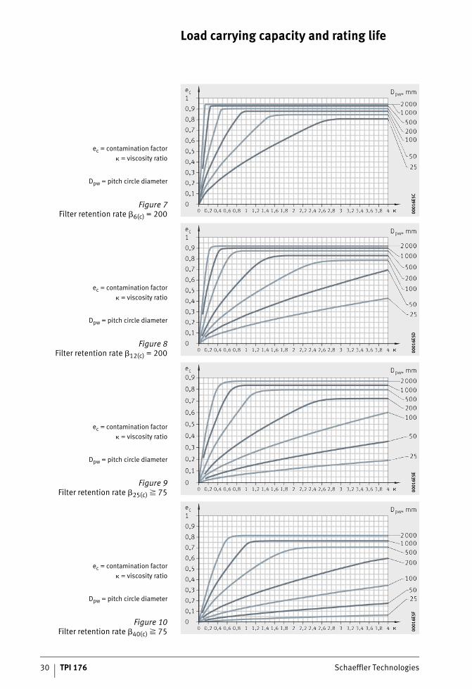
Recirculating oil lubricationwith online oil filtration
For recirculating oil lubrication with continuous oil filtration, the contamination factor eC can be determined by means of diagrams, Figure 7, page 30 to Figure 10, page 30. The diagram to be used is selected on the basis of the filter retention rate βx(c) according to ISO 16889 and the oil cleanliness code according to ISO 4406. The index (c) is the particle size in �m according to ISO 1171, see section Filtration values, page 141.
ST4_3394961035_tragfaehigkeit_.fm Seite 29 Donnerstag, 4. April 2013 10:09 10
30 TPI 176 Schaeffler Technologies
Load carrying capacity and rating life
ec = contamination factor� = viscosity ratio
Dpw = pitch circle diameter
Figure 7Filter retention rate �6(c) = 200 00
016E
5C00
016E
5C
ec = contamination factor� = viscosity ratio
Dpw = pitch circle diameter
Figure 8Filter retention rate �12(c) = 200 00
016E
5D00
016E
5D
ec = contamination factor� = viscosity ratio
Dpw = pitch circle diameter
Figure 9Filter retention rate �25(c) � 75 00
016E
5E00
016E
5E
ec = contamination factor� = viscosity ratio
Dpw = pitch circle diameter
Figure 10Filter retention rate �40(c) � 75 00
016E
5F00
016E
5F
ST4_3394961035_tragfaehigkeit_.fm Seite 30 Donnerstag, 4. April 2013 10:09 10
Schaeffler Technologies TPI 176 31
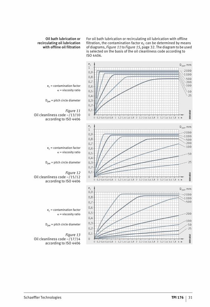
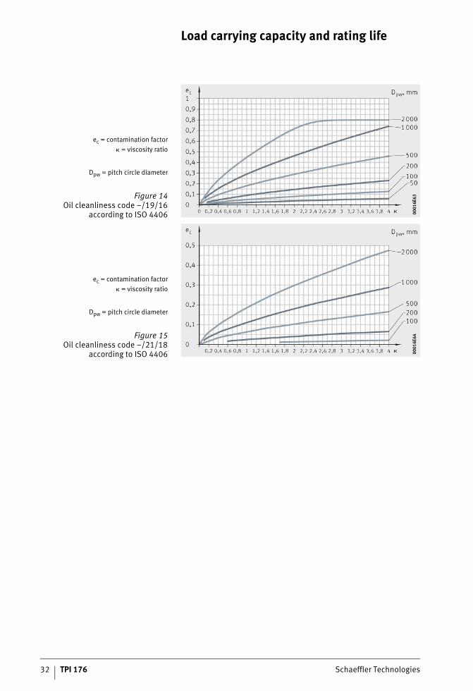
Oil bath lubrication orrecirculating oil lubrication
with offline oil filtration
For oil bath lubrication or recirculating oil lubrication with offline filtration, the contamination factor eC can be determined by means of diagrams, Figure 11 to Figure 15, page 32. The diagram to be used is selected on the basis of the oil cleanliness code according to ISO 4406.
ec = contamination factor� = viscosity ratio
Dpw = pitch circle diameter
Figure 11Oil cleanliness code –/13/10
according to ISO 4406 0001
6E60
0001
6E60
ec = contamination factor� = viscosity ratio
Dpw = pitch circle diameter
Figure 12Oil cleanliness code –/15/12
according to ISO 4406 0001
6E61
0001
6E61
ec = contamination factor� = viscosity ratio
Dpw = pitch circle diameter
Figure 13Oil cleanliness code –/17/14
according to ISO 4406 0001
6E62
0001
6E62
ST4_3394961035_tragfaehigkeit_.fm Seite 31 Donnerstag, 4. April 2013 10:10 10
32 TPI 176 Schaeffler Technologies
Load carrying capacity and rating life
ec = contamination factor� = viscosity ratio
Dpw = pitch circle diameter
Figure 14Oil cleanliness code –/19/16
according to ISO 4406 0001
6E63
0001
6E63
ec = contamination factor� = viscosity ratio
Dpw = pitch circle diameter
Figure 15Oil cleanliness code –/21/18
according to ISO 4406 0001
6E64
0001
6E64
ST4_3394961035_tragfaehigkeit_.fm Seite 32 Donnerstag, 4. April 2013 10:11 10
Schaeffler Technologies TPI 176 33
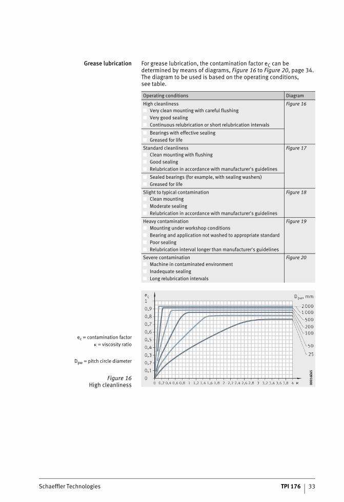
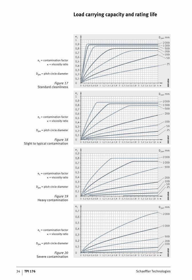
Grease lubrication For grease lubrication, the contamination factor eC can be determined by means of diagrams, Figure 16 to Figure 20, page 34. The diagram to be used is based on the operating conditions, see table.
Operating conditions Diagram
High cleanliness■ Very clean mounting with careful flushing■ Very good sealing■ Continuous relubrication or short relubrication intervals
Figure 16
■ Bearings with effective sealing■ Greased for life
Standard cleanliness■ Clean mounting with flushing■ Good sealing■ Relubrication in accordance with manufacturer's guidelines
Figure 17
■ Sealed bearings (for example, with sealing washers)■ Greased for life
Slight to typical contamination■ Clean mounting■ Moderate sealing■ Relubrication in accordance with manufacturer's guidelines
Figure 18
Heavy contamination■ Mounting under workshop conditions■ Bearing and application not washed to appropriate standard■ Poor sealing■ Relubrication interval longer than manufacturer's guidelines
Figure 19
Severe contamination■ Machine in contaminated environment■ Inadequate sealing■ Long relubrication intervals
Figure 20
ec = contamination factor� = viscosity ratio
Dpw = pitch circle diameter
Figure 16High cleanliness 00
016E
6500
016E
65
ST4_3394961035_tragfaehigkeit_.fm Seite 33 Donnerstag, 4. April 2013 10:12 10
34 TPI 176 Schaeffler Technologies
Load carrying capacity and rating life
ec = contamination factor� = viscosity ratio
Dpw = pitch circle diameter
Figure 17Standard cleanliness 00
016E
6600
016E
66
ec = contamination factor� = viscosity ratio
Dpw = pitch circle diameter
Figure 18Slight to typical contamination 00
016E
6700
016E
67
ec = contamination factor� = viscosity ratio
Dpw = pitch circle diameter
Figure 19Heavy contamination 00
016E
6800
016E
68
ec = contamination factor� = viscosity ratio
Dpw = pitch circle diameter
Figure 20Severe contamination 00
016E
6900
016E
69
ST4_3394961035_tragfaehigkeit_.fm Seite 34 Donnerstag, 4. April 2013 10:12 10
Schaeffler Technologies TPI 176 35
Equivalent operating values The rating life formulae assume a constant bearing load P and con-stant bearing speed n. If the load and speed are not constant, equivalent operating values can be determined that induce the same fatigue as the actual conditions.The equivalent operating values calculated here already take account of the life adjustment factors a3 or aISO. They must not be applied again when calculating the adjusted rating life.
Variable load and speed If the load and speed vary over a time period T, the speed n and equivalent bearing load P are calculated as follows:
Variation in steps If the load and speed vary over a time period T, the speed n and equivalent bearing load P are calculated as follows:
Variable loadat constant speed
If the function F describes the variation in the load over a time period T and the speed is constant, the equivalent bearing load P is calculated as follows:
Load varying in steps andconstant speed
If the load varies in steps over a time period T and the speed is constant, the equivalent bearing load P is calculated as follows:
ST4_3394961035_tragfaehigkeit_.fm Seite 35 Donnerstag, 4. April 2013 10:14 10
36 TPI 176 Schaeffler Technologies
Load carrying capacity and rating life
Constant loadat variable speed
If the speed varies but the load remains constant, the following applies:
Constant loadwith speed varying in steps
If the speed varies in steps but the load remains constant, the following applies:
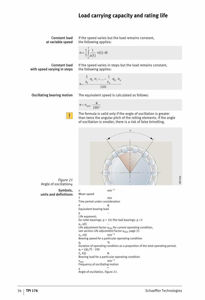
Oscillating bearing motion The equivalent speed is calculated as follows:
The formula is valid only if the angle of oscillation is greater than twice the angular pitch of the rolling elements. If the angle of oscillation is smaller, there is a risk of false brinelling.
Symbols,units and definitions
n min–1
Mean speedT minTime period under considerationP NEquivalent bearing loadp –Life exponent;for roller bearings: p = 10/3for ball bearings: p =3ai, a(t) –Life adjustment factor aISO for current operating condition,see section Life adjustment factor aISO, page 25ni, n(t) min–1
Bearing speed for a particular operating conditionqi %Duration of operating condition as a proportion of the total operating period;qi = (�ti/T) · 100Fi, F(t) NBearing load for a particular operating conditionnosc min–1
Frequency of oscillating motion� °Angle of oscillation, Figure 21.
Figure 21Angle of oscillation� 15
0 13
1a15
0 13
1a
ST4_3394961035_tragfaehigkeit_.fm Seite 36 Donnerstag, 4. April 2013 10:14 10
Schaeffler Technologies TPI 176 37
Friction and increases in temperature
Friction The friction in a rolling bearing is made up of several components, see table. Due to the large number of influencing factors, such as dynamics in speed and load, tilting and skewing resulting from installation, actual frictional torques and frictional energy may deviate significantly from the calculated values. If the frictional torque is an important design criterion, please consult the Schaeffler engineering service.
Frictional component andinfluencing factor
The idling friction is dependent on the lubricant quantity, speed, operating viscosity of the lubricant, seals and the running-in con-dition of the bearing.
Heat dissipation Friction is converted into heat. This must be dissipated from the bearing. The equilibrium between the frictional energy and heat dissipation allows calculation of the thermally safe operating speed n�.
Heat dissipationby the lubricant
if oil lubrication is used, some of the heat is dissipated by the oil. Recirculating oil lubrication with additional cooling is particularly effective.Grease does not give dissipation of heat.
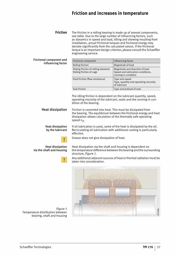
Heat dissipationvia the shaft and housing
Heat dissipation via the shaft and housing is dependent on the temperature difference between the bearing and the surrounding structure, Figure 1.Any additional adjacent sources of heat or thermal radiation must be taken into consideration.
Frictional component Influencing factor
Rolling friction Magnitude of load
Sliding friction of rolling elementsSliding friction of cage
Magnitude and direction of loadSpeed and lubrication conditions, running-in condition
Fluid friction (flow resistance) Type and speedType, quantity and operating viscosity of lubricant
Seal friction Type and preload of seal
Figure 1Temperature distribution between
bearing, shaft and housing 113
352b
113
352b
ST4_3412921355_reibung_und_erw.fm Seite 37 Donnerstag, 4. April 2013 10:15 10
38 TPI 176 Schaeffler Technologies
Friction and increases in temperature
Determiningthe friction values
For this process, the speed and load must be known. The type of lubrication, lubrication method and viscosity of the lubricant at operating temperature are other factors necessary for calculation.
Total frictional torque MR(calculation of axially loaded cylindrical roller bearings,see page 43):
Frictional power NR:
Frictional torque as a function of speed for � · n � 2 000:
Frictional torque as a function of speed for � · n � 2 000:
Frictional torque as a function of load for cylindrical roller bearings:
Frictional torque as a function of load for ball bearings, tapered roller bearings and spherical roller bearings:
MR NmmTotal frictional torqueM0 NmmFrictional torque as a function of speedM1 NmmFrictional torque as a function of loadNR WFrictional powern min–1
Operating speedf0 –Bearing factor for frictional torque as a function of speed,Figure 2, page 39 and tables from page 40 to page 42� mm2s–1
Kinematic viscosity of lubricant at operating temperatureIn the case of grease, the decisive factor is the viscosity of the base oil at operating temperaturedM mmMean bearing diameter (d + D)/2f1 –Bearing factor for frictional torque as a function of load,see tables from page 40 to page 42Fr, Fa NRadial load for radial bearings, axial load for axial bearingsP1 NDecisive load for frictional torque.For ball bearings, tapered roller bearings and spherical roller bearings,see page 42.
ST4_3412921355_reibung_und_erw.fm Seite 38 Donnerstag, 4. April 2013 10:15 10
Schaeffler Technologies TPI 176 39
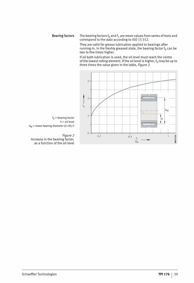
Bearing factors The bearing factors f0 and f1 are mean values from series of tests and correspond to the data according to ISO 15 312.They are valid for grease lubrication applied to bearings after running-in. In the freshly greased state, the bearing factor f0 can be two to five times higher.If oil bath lubrication is used, the oil level must reach the centre of the lowest rolling element. If the oil level is higher, f0 may be up to three times the value given in the table, Figure 2.
f0 = bearing factorh = oil level
dM = mean bearing diameter (d +D)/2
Figure 2Increase in the bearing factor,
as a function of the oil level 0001
722C
0001
722C
ST4_3412921355_reibung_und_erw.fm Seite 39 Donnerstag, 4. April 2013 10:15 10
40 TPI 176 Schaeffler Technologies
Friction and increases in temperature
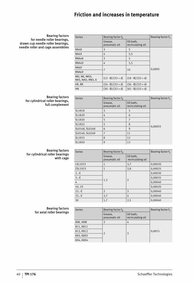
Bearing factorsfor needle roller bearings,
drawn cup needle roller bearings,needle roller and cage assemblies
Bearing factorsfor cylindrical roller bearings,
full complement
Bearing factorsfor cylindrical roller bearings
with cage
Bearing factorsfor axial roller bearings
Series Bearing factor f0 Bearing factor f1
Grease, pneumatic oil
Oil bath, recirculating oil
NA48 3 5
0,0005
NA49 4 5,5
RNA48 3 5
RNA49 4 5,5
NA697 10
RNA69
NKI, NK, NKIS,NKS, NAO, RNO, K (12 · B)/(33 + d) (18 · B)/(33 + d)
HK, BK (24 · B)/(33 + d) (36 · B)/(33 + d)
HN (30 · B)/(33 + d) (45 · B)/(33 + d)
Series Bearing factor f0 Bearing factor f1
Grease, pneumatic oil
Oil bath, recirculating oil
SL1818 3 5
0,00055
SL1829 4 6
SL1830 5 7
SL1822 5 8
SL0148, SL0248 6 9
SL0149, SL0249 7 11
SL1923 8 12
SL1850 9 13
Series Bearing factor f0 Bearing factor f1
Grease, pneumatic oil
Oil bath, recirculating oil
LSL1923 1 3,7 0,00020
ZSL1923 1 3,8 0,00025
2..-E
1,3 2
0,00030
3..-E 0,00035
4 0,00040
10, 19 0,00020
22..-E 2 3 0,00040
23..-E 2,7 4 0,00040
30 1,7 2,5 0,00040
Series Bearing factor f0 Bearing factor f1
Grease, pneumatic oil
Oil bath, recirculating oil
AXK, AXW 3 4
0,0015
811, K811
2 3812, K812
893, K893
894, K894
ST4_3412921355_reibung_und_erw.fm Seite 40 Donnerstag, 4. April 2013 10:16 10
Schaeffler Technologies TPI 176 41
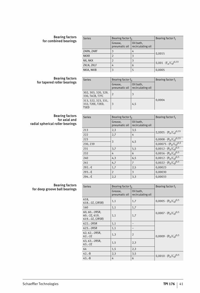
Bearing factorsfor combined bearings
Bearing factorsfor tapered roller bearings
Bearing factorsfor axial and
radial spherical roller bearings
Bearing factorsfor deep groove ball bearings
Series Bearing factor f0 Bearing factor f1
Grease, pneumatic oil
Oil bath, recirculating oil
ZARN, ZARF 3 40,0015
NKXR 2 3
NX, NKX 2 30,001 · (Fa/C0)0,33
ZKLN, ZKLF 4 6
NKIA, NKIB 3 5 0,0005
Series Bearing factor f0 Bearing factor f1
Grease, pneumatic oil
Oil bath, recirculating oil
302, 303, 320, 329, 330, T4CB, T7FC 2 3
0,0004313, 322, 323, 331, 332, T2EE, T2ED, T5ED
3 4,5
Series Bearing factor f0 Bearing factor f1
Grease, pneumatic oil
Oil bath, recirculating oil
213 2,3 3,50,0005 · (P0/C0)0,33
222 2,7 4
2233 4,5
0,0008 · (P0/C0)0,33
230, 239 0,00075 · (P0/C0)0,5
231 3,7 5,5 0,0012 · (P0/C0)0,5
232 4 6 0,0016 · (P0/C0)0,5
240 4,3 6,5 0,0012 · (P0/C0)0,5
241 4,7 7 0,0022 · (P0/C0)0,5
292..-E 1,7 2,5 0,00023
293..-E 2 3 0,00030
294..-E 2,2 3,3 0,00033
Series Bearing factor f0 Bearing factor f1
Grease, pneumatic oil
Oil bath, recirculating oil
618,618..-2Z, (2RSR) 1,1 1,7 0,0005 · (P0/C0)0,5
160 1,1 1,7
0,0007 · (P0/C0)0,560, 60..-2RSR,60..-2Z, 619,619..-2Z, (2RSR)
1,1 1,7
622..-2RSR 1,1 –
0,0009 · (P0/C0)0,5
623..-2RSR 1,1 –
62, 62..-2RSR,62..-2Z 1,3 2
63, 63..-2RSR,63..-2Z 1,5 2,3
64 1,5 2,3
42..-B 2,3 3,50,0010 · (P0/C0)0,5
43..-B 4 6
ST4_3412921355_reibung_und_erw.fm Seite 41 Donnerstag, 4. April 2013 10:16 10
42 TPI 176 Schaeffler Technologies
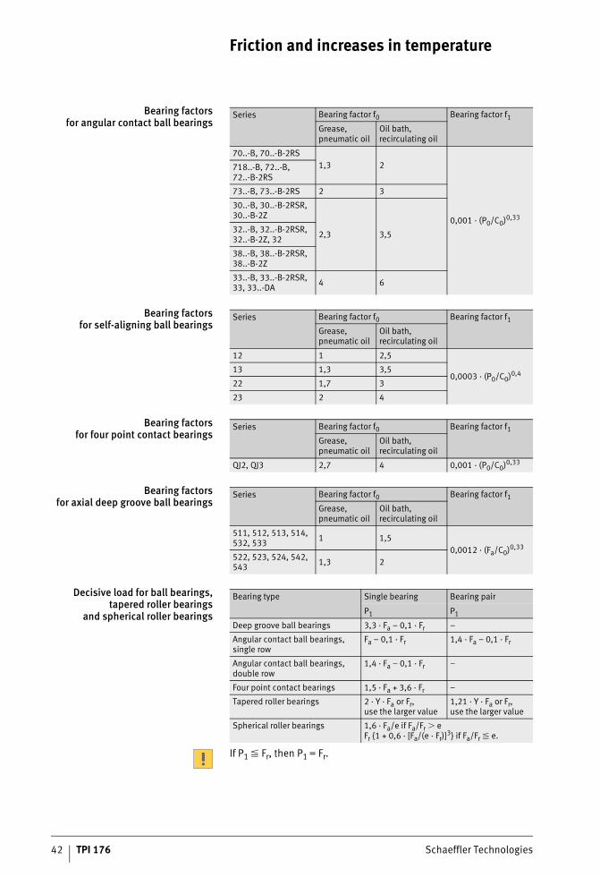
Friction and increases in temperature
Bearing factorsfor angular contact ball bearings
Bearing factorsfor self-aligning ball bearings
Bearing factorsfor four point contact bearings
Bearing factorsfor axial deep groove ball bearings
Decisive load for ball bearings,tapered roller bearings
and spherical roller bearings
If P1 � Fr, then P1 = Fr.
Series Bearing factor f0 Bearing factor f1
Grease, pneumatic oil
Oil bath, recirculating oil
70..-B, 70..-B-2RS1,3 2
0,001 · (P0/C0)0,33
718..-B, 72..-B,72..-B-2RS
73..-B, 73..-B-2RS 2 3
30..-B, 30..-B-2RSR,30..-B-2Z
2,3 3,532..-B, 32..-B-2RSR,32..-B-2Z, 32
38..-B, 38..-B-2RSR,38..-B-2Z
33..-B, 33..-B-2RSR,33, 33..-DA 4 6
Series Bearing factor f0 Bearing factor f1
Grease, pneumatic oil
Oil bath, recirculating oil
12 1 2,5
0,0003 · (P0/C0)0,413 1,3 3,5
22 1,7 3
23 2 4
Series Bearing factor f0 Bearing factor f1
Grease, pneumatic oil
Oil bath, recirculating oil
QJ2, QJ3 2,7 4 0,001 · (P0/C0)0,33
Series Bearing factor f0 Bearing factor f1
Grease, pneumatic oil
Oil bath, recirculating oil
511, 512, 513, 514,532, 533 1 1,5
0,0012 · (Fa/C0)0,33522, 523, 524, 542,543 1,3 2
Bearing type Single bearing Bearing pair
P1 P1
Deep groove ball bearings 3,3 · Fa – 0,1 · Fr –
Angular contact ball bearings, single row
Fa – 0,1 · Fr 1,4 · Fa – 0,1 · Fr
Angular contact ball bearings, double row
1,4 · Fa – 0,1 · Fr –
Four point contact bearings 1,5 · Fa + 3,6 · Fr –
Tapered roller bearings 2 · Y · Fa or Fr,use the larger value
1,21 · Y · Fa or Fr,use the larger value
Spherical roller bearings 1,6 · Fa/e if Fa/Fr � eFr {1 + 0,6 · [Fa/(e · Fr)]
3} if Fa/Fr � e.
ST4_3412921355_reibung_und_erw.fm Seite 42 Donnerstag, 4. April 2013 10:16 10
Schaeffler Technologies TPI 176 43
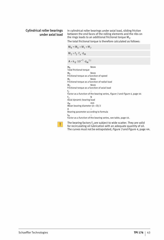
Cylindrical roller bearingsunder axial load
In cylindrical roller bearings under axial load, sliding friction between the end faces of the rolling elements and the ribs on the rings leads to an additional frictional torque M2.The total frictional torque is therefore calculated as follows:
MR NmmTotal frictional torqueM0 NmmFrictional torque as a function of speedM1 NmmFrictional torque as a function of radial loadM2 NmmFrictional torque as a function of axial loadf2 –Factor as a function of the bearing series, Figure 3 and Figure 4, page 44Fa NAxial dynamic bearing loaddM mmMean bearing diameter (d + D)/2A –Bearing parameter according to formulakB –Factor as a function of the bearing series, see table, page 44.
The bearing factors f2 are subject to wide scatter. They are valid for recirculating oil lubrication with an adequate quantity of oil. The curves must not be extrapolated, Figure 3 and Figure 4, page 44.
ST4_3412921355_reibung_und_erw.fm Seite 43 Donnerstag, 4. April 2013 10:16 10
44 TPI 176 Schaeffler Technologies
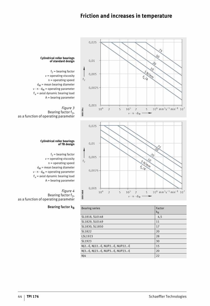
Friction and increases in temperature
Bearing factor kB
Cylindrical roller bearingsof standard design
f2 = bearing factor� = operating viscosity
n = operating speeddM = mean bearing diameter
� · n · dM = operating parameterFa = axial dynamic bearing load
A = bearing parameter
Figure 3Bearing factor f2,
as a function of operating parameter 0001
39cc
0001
39cc
Cylindrical roller bearingsof TB design
f2 = bearing factor� = operating viscosity
n = operating speeddM = mean bearing diameter
� · n · dM = operating parameterFa = axial dynamic bearing load
A = bearing parameter
Figure 4Bearing factor f2,
as a function of operating parameter 0001
36b8
0001
36b8
Bearing series FactorkB
SL1818, SL0148 4,5
SL1829, SL0149 11
SL1830, SL1850 17
SL1822 20
LSL1923 28
SL1923 30
NJ2..-E, NJ22..-E, NUP2..-E, NUP22..-E 15
NJ3..-E, NJ23..-E, NUP3..-E, NUP23..-E 20
NJ4 22
ST4_3412921355_reibung_und_erw.fm Seite 44 Donnerstag, 4. April 2013 10:16 10
Schaeffler Technologies TPI 176 45
Speeds On the basis of DIN 732-1, calculation of the thermal reference speed nB has been standardised in ISO 15 312. The calculation of reference speeds has been matched to this standard.
Thermal reference speed The thermal reference speed nB is used as an ancillary value when calculating the thermally safe operating speed n�. This is the speed at which, under defined reference conditions, a bearing operating temperature of +70 °C is reached.
Reference conditions The reference conditions are based on the usual operating condi-tions of the most significant bearing types and sizes.They are defined in ISO 15 312 as follows:■ mean ambient temperature �Ar = +20 °C■ mean bearing temperature at the outer ring �r = +70 °C■ load on radial bearings P1r = 0,05 · C0r■ load on axial bearings P1a = 0,02 · C0aoperating viscosities (axial bearings according to DIN 732-1) For radial bearings, the reference speeds are approximately the same for oil and grease lubrication:
– radial bearings: 12 mm2s–1 (ISO VG 32)– axial bearings: 24 mm2s–1 (ISO VG 68)
■ heat dissipation via the bearing seating surfaces, see section Bearing seating surface Ar � 50 000 mm2 and section Bearing seating surface Ar � 50 000 mm2.
Bearing seating surfaceAr � 50 000 mm2
Radial bearings have a heat dissipation value qr = 0,016 W/mm2.Axial bearings have a heat dissipation value qr = 0,02 W/mm2.
Bearing seating surfaceAr � 50 000 mm2
For radial bearings, the heat dissipation in W/mm2 is:
For axial bearings, the heat dissipation in W/mm2 is:
Ar mm2
Bearing seating surfaceqr W/mm2
Heat dissipation.
ST4_3412921355_reibung_und_erw.fm Seite 45 Donnerstag, 4. April 2013 10:17 10
46 TPI 176 Schaeffler Technologies
Friction and increases in temperature
Limiting speed The limiting speed nG is based on practical experience andtakes account of additional criteria such as smooth running,sealing function and centrifugal forces.The limiting speed must not be exceeded even under favourable operating and cooling conditions.
Thermally safe operatingspeed
The thermally safe operating speed n� is calculated according to E DIN 732:2008. The basis for the calculation is the heat balance in the bearing, the equilibrium between the frictional energy as a function of speed and the heat dissipation as a function of tem-perature. When conditions are in equilibrium, the bearing tem-perature is constant. The permissible operating temperature determines the thermally safe operating speed n� of the bearing. The preconditions for calcu-lation are correct fitting, normal operating clearance and constant operating conditions.The calculation method is not valid for:■ sealed bearings with contact seals, since the maximum speed
is restricted by the permissible sliding speed at the seal lip■ yoke and stud type track rollers■ aligning needle roller bearings■ axial deep groove and axial angular contact ball bearings.Bearings with special cages (such as TBH, T9H) are capable, due to their cage designs, of speeds that are higher than those calculated according to this method.The limiting speed nG must always be observed.
ST4_3412921355_reibung_und_erw.fm Seite 46 Donnerstag, 4. April 2013 10:17 10
Schaeffler Technologies TPI 176 47
Calculation of the thermally safeoperating speed
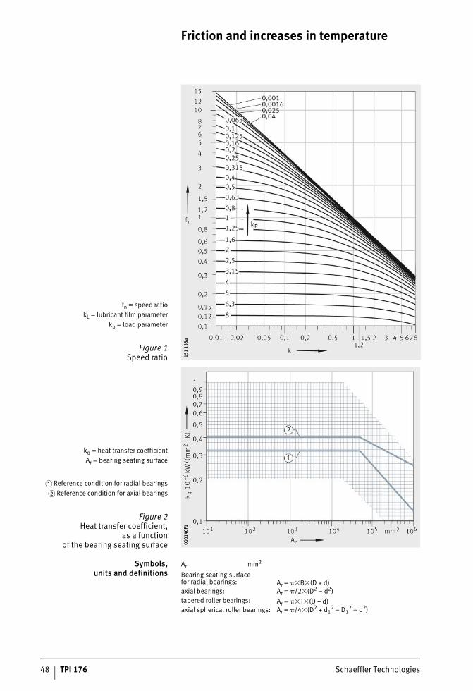
The thermally safe operating speed n� is a product of the reference speed nB and the speed ratio fn:
The speed ratio is derived from Figure 1, page 48:
In the normal range 0,01 � kL � 10 and 0,01 � kP � 10, fn can be calculated using an approximation formula:
Heat dissipation via the bearing seating surfaces QS, Figure 2, page 48:
Heat dissipation by the lubricant QL:
Total dissipated heat flow Q:
Lubricant film parameter kL:
Load parameter kP:
ST4_3412921355_reibung_und_erw.fm Seite 47 Donnerstag, 4. April 2013 10:17 10
48 TPI 176 Schaeffler Technologies
Friction and increases in temperature
Symbols,units and definitions
Ar mm2
fn = speed ratiokL = lubricant film parameter
kp = load parameter
Figure 1Speed ratio 15
1 15
5a15
1 15
5a
kq = heat transfer coefficientAr = bearing seating surface
� Reference condition for radial bearings� Reference condition for axial bearings
Figure 2Heat transfer coefficient,
as a functionof the bearing seating surface 00
0140
F100
0140
F1
Bearing seating surfacefor radial bearings: Ar = ��B�(D + d)axial bearings: Ar = �/2�(D2 – d2)tapered roller bearings: Ar = ��T�(D + d)axial spherical roller bearings: Ar = �/4�(D2 + d1
2 – D12 – d2)
ST4_3412921355_reibung_und_erw.fm Seite 48 Donnerstag, 4. April 2013 10:17 10
Schaeffler Technologies TPI 176 49
Symbols,units and definitions
continued
B mmBearing widthd mmBearing bore diameterd1 mmOutside diameter of shaft locating washerD mmBearing outside diameterD1 mmInside diameter of housing locating washerdM mmMean bearing diameter (D + d)/2f0 –Bearing factor for frictional torque as a function of speed,see section Bearing factors, page 39f1 –Bearing factor for frictional torque as a function of load,see section Bearing factors, page 39fn –Speed ratio, Figure 1, page 48kL –Lubricant film parameterkP –Load parameterkq 10–6 kW/(mm2 · K)Heat transfer coefficient of bearing seating surface, Figure 2, page 48It is dependent on the housing design and size, the housing material and the mounting position In normal applications, the heat transfer coefficient of bearing seating surfaces up to 25 000 mm2 is between 0,2 · 10–6 kW/(mm2 · K) and 1,0 · 10–6 kW/(mm2 · K)n� min–1
Thermally safe operating speednB min–1
Reference speed according to dimension tablesP1 NRadial load for radial bearings, axial load for axial bearingsqr W/mm2
Heat flow densityQ kWTotal dissipated heat flowQE kWHeat flow due to heating by external sourceQL kWHeat flow dissipated by the lubricantQS kWHeat flow dissipated via the bearing seating surfacesT mmTotal width of tapered roller bearingVL l/minOil flow��A KDifference between mean bearing temperature and ambient temperature��L KDifference between oil input temperature and oil output temperature� mm2s–1
Kinematic viscosity of the lubricant at operating temperature.
ST4_3412921355_reibung_und_erw.fm Seite 49 Donnerstag, 4. April 2013 10:18 10
50 TPI 176 Schaeffler Technologies
Friction and increases in temperature
Operating temperature The operating temperature of a bearing arrangement increases after startup. Once an equilibrium has been achieved between heat generation and heat dissipation, the temperature remains constant.This equilibrium temperature �B can be calculated using the for-mulae for the heat flow generated by the bearing Qbearing and the heat flow dissipated to the environment QS. It is heavily dependent on the temperature difference between the bearing, adjacent parts and environment.If the data Kt and qLB required here are known (possibly as a result of tests), the thermal balance can be used to derive the equilibrium temperature �B.
Generated heat flow Heat flow generated by bearing friction:
Dissipated heat flow Heat flow dissipated to the environment:
Additional dissipated heat flow In the case of recirculating oil lubrication, the oil additionally dissipates heat. The dissipated heat flow L can be determined in the case of normal mineral oils using � = 0,89 g/cm3:
Equilibrium temperature The equilibrium temperature of the bearing is determined by equat-ing the heat introduced and heat dissipated ( bearing = S + L) and resolving it by �B:
Qbearing WHeat flow due to bearing frictionNR WFrictional powerMR NmmTotal frictional torquen min–1
Operating speed�B °COperating temperature�U °CAmbient temperature.
The temperature prediction derived from such a calculation is relatively imprecise, since the values to be inputted are generally not known to a precise degree. A secure basis can only be obtainedif the equilibrium temperature is determined in a test run.
ST4_3412921355_reibung_und_erw.fm Seite 50 Donnerstag, 4. April 2013 10:18 10

Schaeffler Technologies TPI 176 51
ST4_3412921355_reibung_und_erw.fm Seite 51 Donnerstag, 4. April 2013 10:19 10
Lubrication methods
#tpi176__en_gb__de.xml_FM8_en_gb.book Seite 52 Donnerstag, 4. April 2013 8:22 08
Schaeffler Technologies TPI 176 53
Page
Lubrication methods
Lubrication methods Grease lubrication .................................................................... 54
Oil lubrication........................................................................... 54
Selection of the lubrication method........................................... 55
Examples from practice............................................................. 55Individual supply ................................................................. 55Central supply...................................................................... 56
ST4_3444132235_ivz.fm Seite 53 Donnerstag, 4. April 2013 10:20 10
54 TPI 176 Schaeffler Technologies
Lubrication methods
When a machine is being designed, the method to be used for lubri-cation of the rolling bearings should be defined as early as possible. A decision may be made in favour of grease or oil lubrication, or in special cases lubrication by means of solid substances.
Grease lubrication Grease lubrication is used in approx. 90 % of all rolling bearing arrangements.The advantages of grease lubrication include:■ very little design work required■ sealing action supported by the grease■ long operating life with maintenance-free lubrication,
eliminating the requirement for lubrication devices■ suitability for speed parameters n ·dM � 2,6 · 106 min–1 · mm■ longer emergency running phase in case of lubrication supply
failure■ low frictional torque.Under normal operating and environmental conditions, lifetime lubrication (lubrication for life) is often possible.If high demands are present, for example in terms of speed, tem-perature and load, it will be necessary to plan for relubrication at appropriate time intervals. In this case, it is necessary to provide inlet and outlet ducts for grease as well as a collection chamber for used grease. If short relubrication intervals are to be used, it may also be necessary to provide a grease pump and a regulator for the grease quantity.
Oil lubrication Oil lubrication presents itself as a sensible option if adjacent machine elements are already supplied with oil or if heat is to be dissipated by the lubricant. Heat dissipation may be necessary if high speeds or loads are present or if the bearing arrangement is subjected to heating by an external source.If minimal quantity lubrication is used, small quantities of oil can be metered precisely. This can be achieved by means of oil drop lubri-cation, oil pulse lubrication or pneumatic oil lubrication. This offers the advantage that splash losses are prevented and bearing friction is kept to a low level. The use of air as a carrier allows targeted feed and flow, giving support to the sealing arrangement.Oil injection lubrication can be used to achieve targeted supply to all the contact points in rapidly rotating bearings as well as good cooling.
ST4_3444164747_schmierverfahre.fm Seite 54 Donnerstag, 4. April 2013 10:20 10
Schaeffler Technologies TPI 176 55
Selectionof the lubrication method
When selecting a method for lubricating bearings, attention must be paid to:■ operating conditions■ running behaviour■ running noise■ friction■ temperature■ operational reliability (security against premature failure
as a result of wear, fatigue, corrosion or damage due to media introduced from the environment, such as water or sand)
■ costs for installation and maintenance of the lubrication system.In order to achieve high operational reliability, the lubricant supply to the bearings must be free from disruptions and the lubricant must continuously reach all the functional surfaces. An adequate quantity of lubricant is not achieved at all times with all lubrication methods. A reliable supply is facilitated by a monitored and continuous oil feed. Where oil sump lubrication is used and there are high require-ments for operational reliability, the oil level must be checked on a regular basis.Bearings lubricated with grease have sufficient operational reliability if the relubrication intervals or the grease operating life (in the case of bearing arrangements lubricated for life) are not exceeded.Where lubrication methods with relubrication at short intervals are used, the operational reliability depends on the reliability of the supply devices.Common lubrication methods are shown in the table Lubrication methods, page 60.
Examples from practice Lubrication methods are subdivided into methods for individual supply and central supply. Which variant is used is based on the number of lubrication points to be supplied.
Individual supply If there are only a few lubrication points or they are situated some distance from each other, individual supply should be used in preference. In this case, lubrication with grease is recommended. This can be carried out either manually using a grease gun or by means of automatic MOTION GUARD lubricators. These dispense their fill quantity to the lubrication point over an adjustable time period.For further information, see TPI 168, Arcanol Rolling Bearing Greases.
ST4_3444164747_schmierverfahre.fm Seite 55 Donnerstag, 4. April 2013 10:20 10
56 TPI 176 Schaeffler Technologies
Lubrication methods
Central supply If lubricant is to be supplied to a large number of lubrication points, possibly with differing lubricant demand, central supply or a central lubrication system is a sensible option. This can be a consumption lubrication system or a recirculating lubrication system.
Consumption lubrication systems In the case of consumption lubrication systems, the lubricant is fed to the lubrication point once only and the quantities fed are normally small. Consumption lubrication systems are suitable for oils and flowable greases of the NLGI grades 0, 00 or 000 (NLGI: National Lubricating Grease Institute), see section NLGI grade, page 66.They generally comprise a pump installed in the storage container, the controller (operating on a time-controlled or cycle-controlled basis), the metering valves, the feed lines to the metering valves and the feed lines from the metering points to the lubrication points.The lubricant demand for each bearing position can be set specifi-cally by means of the metering quantity for each metering valve (5 mm3 to 1 000 mm3, in various stages) and the pump pulse. If greasing is to be carried out using greases with higher consistency of the NLGI grade 1, 2 or 3, special central lubrication systems must be used. These can be so-called twin-line, progressive line or multi-line systems. The lubricant demand for each bearing position can be specifically adjusted by means of appropriate metering elements in these systems as well. A special type of consumption lubrication system is the pneumatic oil lubrication system, Figure 1 and Figure 2, page 57.The conveying capability of the grease must be clarified with the equipment manfacturer.
Principle appliedby Woerner GmbH & Co. KG, Wertheim
� Oil line� Air line
� Pneumatic oil lineto the lubrication point
Figure 1Pneumatic oil lubrication 00
0170
A900
0170
A9
ST4_3444164747_schmierverfahre.fm Seite 56 Donnerstag, 4. April 2013 10:20 10
Schaeffler Technologies TPI 176 57
On a periodic basis, a metering valve feeds a certain oil quantity into a mixing valve and it is exposed there to a continuous air flow. As a result, the metered oil quantity is very finely distributed on the wall of the lubrication point line and the lubrication point is continuously supplied with very small quantities of lubricant. The frictional torque does not increase during relubrication and splash losses are minimised. The requisite length and diameter of the lubrication point line as well as the air pressure to be selected must be agreed in consultation with the equipment manufacturer. Pneumatic oil lubrication has superseded the oil mist lubrication used previously, since it gives smoother feed and can be set accurately.
� Time-controlled oil pump� Oil line� Air line
� Oil/air mixing unit� Oil metering unit� Air metering unit� Mixing chamber
Pneumatic oil lineto the lubrication point
Figure 2Schematic
of pneumatic oil lubrication 0001
70A8
0001
70A8
ST4_3444164747_schmierverfahre.fm Seite 57 Donnerstag, 4. April 2013 10:20 10
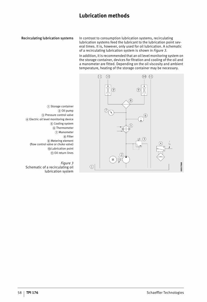
58 TPI 176 Schaeffler Technologies
Lubrication methods
Recirculating lubrication systems In contrast to consumption lubrication systems, recirculating lubrication systems feed the lubricant to the lubrication point sev-eral times. It is, however, only used for oil lubrication. A schematic of a recirculating lubrication system is shown in Figure 3. In addition, it is recommended that an oil level monitoring system on the storage container, devices for fitration and cooling of the oil and a manometer are fitted. Depending on the oil viscosity and ambient temperature, heating of the storage container may be necessary.
� Storage container� Oil pump
� Pressure control valve� Electric oil level monitoring device
� Cooling system� Thermometer
� Manometer Filter
Metering element(flow control valve or choke valve)
�� Lubrication point� Oil return lines
Figure 3Schematic of a recirculating oil
lubrication system 0001
70AA
0001
70AA
ST4_3444164747_schmierverfahre.fm Seite 58 Donnerstag, 4. April 2013 10:20 10
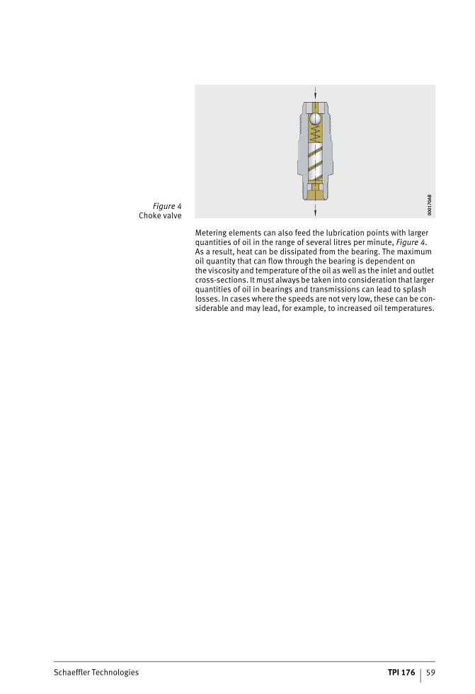
Schaeffler Technologies TPI 176 59
Metering elements can also feed the lubrication points with larger quantities of oil in the range of several litres per minute, Figure 4. As a result, heat can be dissipated from the bearing. The maximum oil quantity that can flow through the bearing is dependent on the viscosity and temperature of the oil as well as the inlet and outlet cross-sections. It must always be taken into consideration that larger quantities of oil in bearings and transmissions can lead to splash losses. In cases where the speeds are not very low, these can be con-siderable and may lead, for example, to increased oil temperatures.
Figure 4Choke valve 00
0170
AB00
0170
AB
ST4_3444164747_schmierverfahre.fm Seite 59 Donnerstag, 4. April 2013 10:21 10
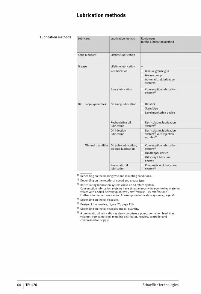
Lubrication methods
60 TPI 176 Schaeffler Technologies
Lubrication methods
1) Depending on the bearing type and mounting conditions.2) Depending on the rotational speed and grease type.3) Recirculating lubrication systems have an oil return system.
Consumption lubrication systems have simultaneously time-controlled metering valves with a small delivery quantity (5 mm3/stroke – 10 mm3/stroke ).Further information: see section Consumption lubrication systems, page 56.
4) Depending on the oil viscosity.5) Design of the nozzles, Figure 20, page 116.6) Depending on the oil viscosity and oil quantity.7) A pneumatic oil lubrication system comprises a pump, container, feed lines,
volumetric pneumatic oil metering distributor, nozzles, controller and compressed air supply.
Lubricant Lubrication method Equipmentfor the lubrication method
Solid lubricant Lifetime lubrication –
Grease Lifetime lubrication –
Relubrication ■ Manual grease gun■ Grease pump■ Automatic relubrication
systems
Spray lubrication ■ Consumption lubrication system3)
Oil Larger quantities Oil sump lubrication ■ Dipstick■ Standpipe■ Level monitoring device
Recirculating oil lubrication
■ Recirculating lubrication system3)
Oil injection lubrication
■ Recirculating lubrication system3) with injection nozzles5)
Minimal quantities Oil pulse lubrication, oil drop lubrication
■ Consumption lubrication system3)
■ Oil dropper device■ Oil spray lubrication
system
Pneumatic oil lubrication
■ Pneumatic oil lubrication system7)
ST4_3444164747_schmierverfahre.fm Seite 60 Donnerstag, 4. April 2013 10:21 10
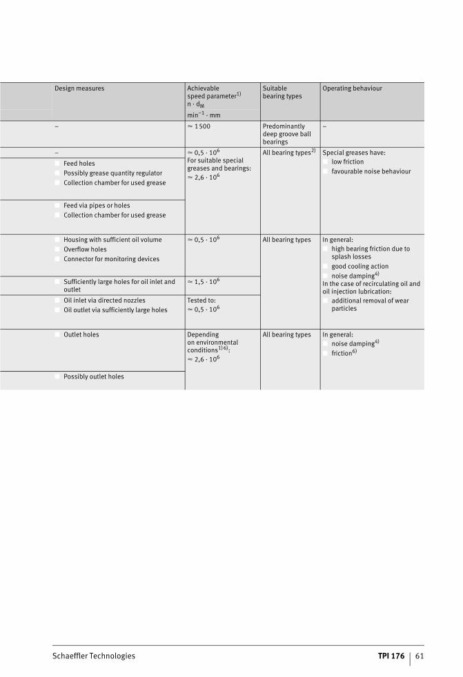
Schaeffler Technologies TPI 176 61
Design measures Achievable speed parameter1)
n · dM
Suitable bearing types
Operating behaviour
min–1 · mm
– � 1500 Predominantly deep groove ball bearings
–
– � 0,5 · 106
For suitable special greases and bearings:� 2,6 · 106
All bearing types2) Special greases have:■ low friction■ favourable noise behaviour
■ Feed holes■ Possibly grease quantity regulator■ Collection chamber for used grease
■ Feed via pipes or holes■ Collection chamber for used grease
■ Housing with sufficient oil volume■ Overflow holes■ Connector for monitoring devices
� 0,5 · 106 All bearing types In general:■ high bearing friction due to
splash losses■ good cooling action■ noise damping4)
In the case of recirculating oil and oil injection lubrication:■ additional removal of wear
particles
■ Sufficiently large holes for oil inlet and outlet
� 1,5 · 106
■ Oil inlet via directed nozzles■ Oil outlet via sufficiently large holes
Tested to:� 0,5 · 106
■ Outlet holes Depending on environmental conditions1)6):� 2,6 · 106
All bearing types In general:■ noise damping4)
■ friction6)
■ Possibly outlet holes
ST4_3444164747_schmierverfahre.fm Seite 61 Donnerstag, 4. April 2013 10:21 10
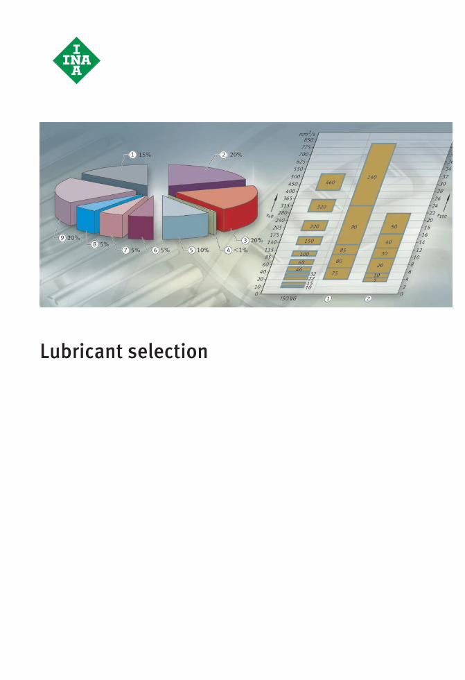
Lubricant selection
#tpi176__en_gb__de.xml_FM8_en_gb.book Seite 62 Donnerstag, 4. April 2013 8:22 08
Schaeffler Technologies TPI 176 63
Page
Lubricant selection
Lubricant selection Greases .................................................................................... 65The influence of bearing type................................................ 66The influence of speed ......................................................... 67The influence of temperature ................................................ 69The influence of load ............................................................ 73The influence of water and moisture ..................................... 73The influence of oscillations, shocks and vibrations.............. 73The influence of nuclear radiation......................................... 74The influence of vacuum....................................................... 75The influence of seals........................................................... 75The influence of mounting position and adjacent components........................................................... 76The influence of legal and environmental regulations............ 76
Lubricating oils ......................................................................... 77Recommended oil viscosity .................................................. 78Selection of oil in accordance with operating conditions..................................................... 81Selection of oil in accordance with oil characteristics ......................................................... 82
Special applications Lubricants with biological degradability .................................... 88
Ceramic and hybrid bearings..................................................... 88
ST4_3179113355_ivz.fm Seite 63 Donnerstag, 4. April 2013 10:22 10
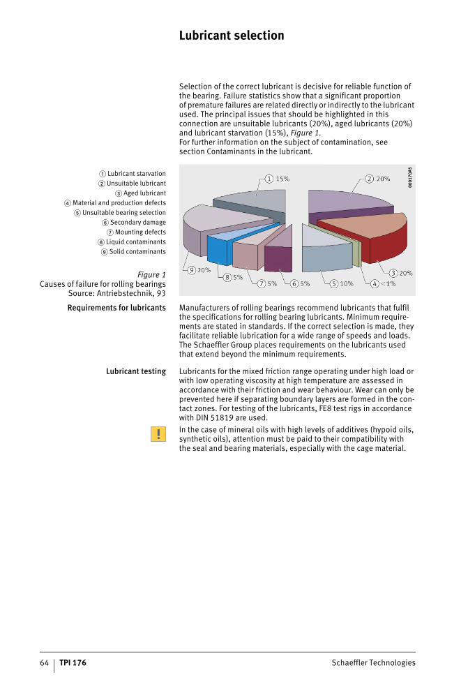
64 TPI 176 Schaeffler Technologies
Lubricant selection
Selection of the correct lubricant is decisive for reliable function of the bearing. Failure statistics show that a significant proportion of premature failures are related directly or indirectly to the lubricant used. The principal issues that should be highlighted in this connection are unsuitable lubricants (20%), aged lubricants (20%) and lubricant starvation (15%), Figure 1. For further information on the subject of contamination, see section Contaminants in the lubricant.
Requirements for lubricants Manufacturers of rolling bearings recommend lubricants that fulfil the specifications for rolling bearing lubricants. Minimum require-ments are stated in standards. If the correct selection is made, they facilitate reliable lubrication for a wide range of speeds and loads. The Schaeffler Group places requirements on the lubricants used that extend beyond the minimum requirements.
Lubricant testing Lubricants for the mixed friction range operating under high load or with low operating viscosity at high temperature are assessed in accordance with their friction and wear behaviour. Wear can only be prevented here if separating boundary layers are formed in the con-tact zones. For testing of the lubricants, FE8 test rigs in accordance with DIN 51819 are used.In the case of mineral oils with high levels of additives (hypoid oils, synthetic oils), attention must be paid to their compatibility with the seal and bearing materials, especially with the cage material.
� Lubricant starvation� Unsuitable lubricant
� Aged lubricant� Material and production defects
� Unsuitable bearing selection� Secondary damage
� Mounting defects Liquid contaminants Solid contaminants
Figure 1Causes of failure for rolling bearings
Source: Antriebstechnik, 93
0001
70A5
0001
70A5
ST4_3466890763_schmierstoffaus.fm Seite 64 Donnerstag, 4. April 2013 10:22 10
Schaeffler Technologies TPI 176 65
Greases The optimum bearing operating life can be achieved if suitable lubri-cants are selected. Account must be taken of application-related influencing factors such as bearing type, speed, temperature and load. In addition, attention must be paid to environmental condi-tions, the resistance of plastics, legal and enironmental regulations as well as costs.
Specification according to DIN orthe design brief
Type K greases standardised in accordance with DIN 51825 should be used in preference. However, this standard only formulates mini-mum requirements for greases. This means that greases in one DIN class may exhibit differences in quality and may be suitable to vary-ing degrees for the specific application. As a result, rolling bearing manufacturers frequently specify greases by means of design briefs that give a more detailed description of the profile of requirements for the grease.
Characteristics The characteristics of a grease are fundamentally dependent on:■ the base oil type■ the base oil viscosity (which is responsible for the formation
of the lubricant film)■ the thickener (which is relevant to shear strength)■ the additive package.The thickeners normally used are metal soaps or metal complex soaps. Organic or polymer thickeners such as polycarbamide are increasing in importance.PTFE is used as a solid lubricant for lubrication in the high tempera-ture range (continuous temperature � +150 °C) or media resistance. Inorganic thickeners such as bentonite are only used to a lesser extent in modern greases.As a base oil, mineral oils or synthetic oils are used. It is important that synthetic oils are differentiated according to their type (polyalphaolefin, polyglycol, ester, fluoro oil), since these possess very different characteristics.In addition, greases contain additives. A distinction is made between additives that have an effect on the oil itself (oxidation inhibitors, viscosity index improvers, detergents, dispersants) and additives that have an effect on the bearing or the metal surface (anti-wear additives, corrosion inhibitors, friction value modifiers).
ST4_3466890763_schmierstoffaus.fm Seite 65 Donnerstag, 4. April 2013 10:23 10
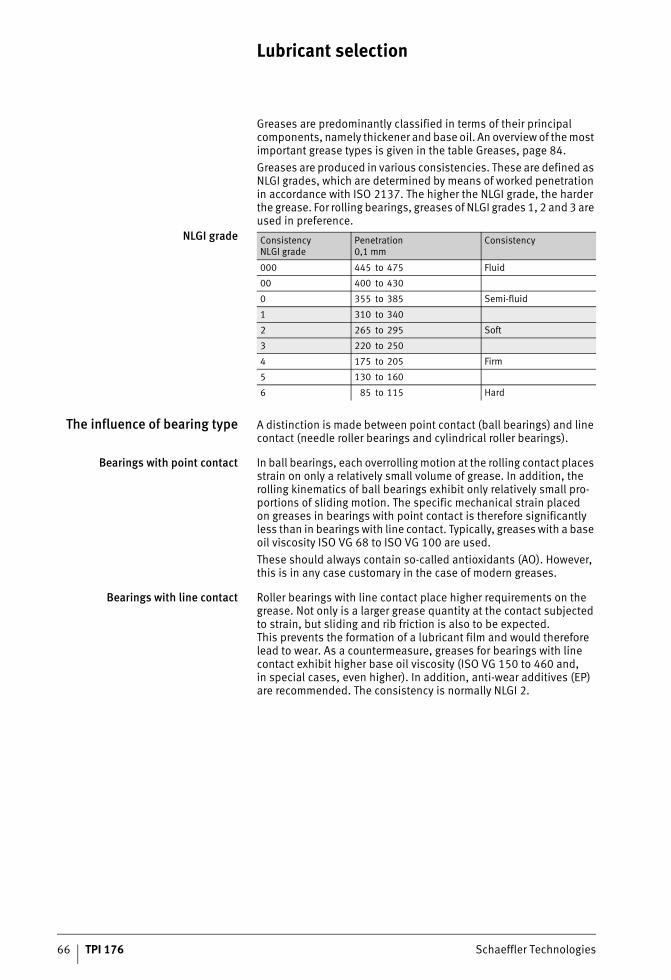
66 TPI 176 Schaeffler Technologies
Lubricant selection
Greases are predominantly classified in terms of their principal components, namely thickener and base oil. An overview of the most important grease types is given in the table Greases, page 84.Greases are produced in various consistencies. These are defined as NLGI grades, which are determined by means of worked penetration in accordance with ISO 2137. The higher the NLGI grade, the harder the grease. For rolling bearings, greases of NLGI grades 1, 2 and 3 are used in preference.
NLGI grade
The influence of bearing type A distinction is made between point contact (ball bearings) and line contact (needle roller bearings and cylindrical roller bearings).
Bearings with point contact In ball bearings, each overrolling motion at the rolling contact places strain on only a relatively small volume of grease. In addition, the rolling kinematics of ball bearings exhibit only relatively small pro-portions of sliding motion. The specific mechanical strain placed on greases in bearings with point contact is therefore significantly less than in bearings with line contact. Typically, greases with a base oil viscosity ISO VG 68 to ISO VG 100 are used. These should always contain so-called antioxidants (AO). However, this is in any case customary in the case of modern greases.
Bearings with line contact Roller bearings with line contact place higher requirements on the grease. Not only is a larger grease quantity at the contact subjected to strain, but sliding and rib friction is also to be expected. This prevents the formation of a lubricant film and would therefore lead to wear. As a countermeasure, greases for bearings with line contact exhibit higher base oil viscosity (ISO VG 150 to 460 and, in special cases, even higher). In addition, anti-wear additives (EP) are recommended. The consistency is normally NLGI 2.
Consistency NLGI grade
Penetration0,1 mm
Consistency
000 445 to 475 Fluid
00 400 to 430
0 355 to 385 Semi-fluid
1 310 to 340
2 265 to 295 Soft
3 220 to 250
4 175 to 205 Firm
5 130 to 160
6 85 to 115 Hard
ST4_3466890763_schmierstoffaus.fm Seite 66 Donnerstag, 4. April 2013 10:23 10
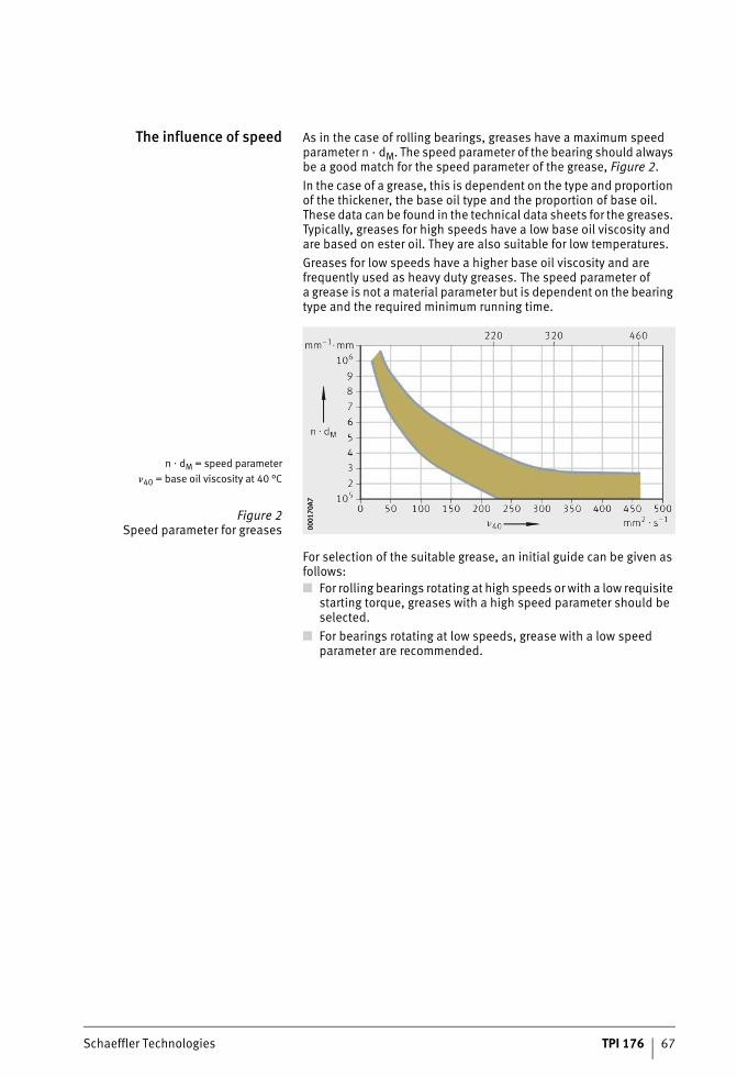
Schaeffler Technologies TPI 176 67
The influence of speed As in the case of rolling bearings, greases have a maximum speed parameter n · dM. The speed parameter of the bearing should always be a good match for the speed parameter of the grease, Figure 2.In the case of a grease, this is dependent on the type and proportion of the thickener, the base oil type and the proportion of base oil. These data can be found in the technical data sheets for the greases. Typically, greases for high speeds have a low base oil viscosity and are based on ester oil. They are also suitable for low temperatures.Greases for low speeds have a higher base oil viscosity and are frequently used as heavy duty greases. The speed parameter of a grease is not a material parameter but is dependent on the bearing type and the required minimum running time.
For selection of the suitable grease, an initial guide can be given as follows:■ For rolling bearings rotating at high speeds or with a low requisite
starting torque, greases with a high speed parameter should be selected.
■ For bearings rotating at low speeds, grease with a low speed parameter are recommended.
n � dM = speed parameter�40 = base oil viscosity at 40 °C
Figure 2Speed parameter for greases 00
0170
A700
0170
A7
ST4_3466890763_schmierstoffaus.fm Seite 67 Donnerstag, 4. April 2013 10:23 10
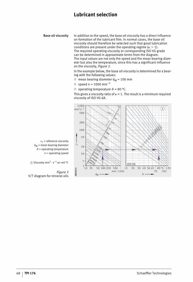
68 TPI 176 Schaeffler Technologies
Lubricant selection
Base oil viscosity In addition to the speed, the base oil viscosity has a direct influence on formation of the lubricant film. In normal cases, the base oil viscosity should therefore be selected such that good lubrication conditions are present under the operating regime (� � 1). The required operating viscosity or corresponding ISO VG grade can be determined in approximate terms from the diagram. The input values are not only the speed and the mean bearing diam-eter but also the temperature, since this has a significant influence on the viscosity, Figure 3.In the example below, the base oil viscosity is determined for a bear-ing with the following values:■ mean bearing diameter dM = 100 mm■ speed n = 1000 min–1
■ operating temperature � = 80 °C.This gives a viscosity ratio of � = 1. The result is a minimum required viscosity of ISO VG 68.
�1 = reference viscositydM = mean bearing diameter
� = operating temperaturen = operating speed
� Viscosity mm2 · s–1 at +40 °C
Figure 3V/T diagram for mineral oils 00
016C
2100
016C
21
ST4_3466890763_schmierstoffaus.fm Seite 68 Donnerstag, 4. April 2013 10:23 10
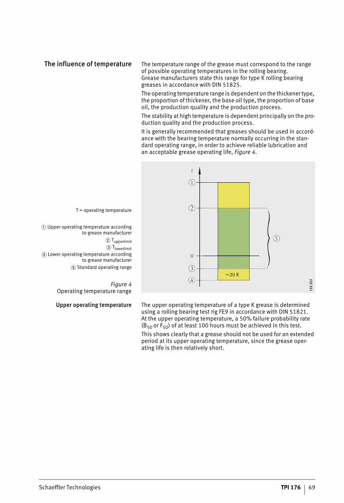
Schaeffler Technologies TPI 176 69
The influence of temperature The temperature range of the grease must correspond to the range of possible operating temperatures in the rolling bearing.Grease manufacturers state this range for type K rolling bearing greases in accordance with DIN 51825.The operating temperature range is dependent on the thickener type, the proportion of thickener, the base oil type, the proportion of base oil, the production quality and the production process.The stability at high temperature is dependent principally on the pro-duction quality and the production process.It is generally recommended that greases should be used in accord-ance with the bearing temperature normally occurring in the stan-dard operating range, in order to achieve reliable lubrication and an acceptable grease operating life, Figure 4.
Upper operating temperature The upper operating temperature of a type K grease is determined using a rolling bearing test rig FE9 in accordance with DIN 51821. At the upper operating temperature, a 50% failure probability rate (B50 or F50) of at least 100 hours must be achieved in this test.This shows clearly that a grease should not be used for an extended period at its upper operating temperature, since the grease oper-ating life is then relatively short.
T = operating temperature
� Upper operating temperature accordingto grease manufacturer
� Tupperlimit� Tlowerlimit
� Lower operating temperature accordingto grease manufacturer
� Standard operating range
Figure 4Operating temperature range 15
5 25
215
5 25
2
ST4_3466890763_schmierstoffaus.fm Seite 69 Donnerstag, 4. April 2013 10:23 10
70 TPI 176 Schaeffler Technologies
Lubricant selection
Dropping point Data sheets for greases also state the dropping point, which is deter-mined in accordance with ISO 2176. The dropping point is defined as the temperature at which slowly heated grease passes from a semi-solid to a liquid state and the first drop of grease falls from the standardised dropping point nipple. The dropping point is fundamentally dependent on the type of thickener and less so on the base oil. When this temperature is reached, the structure of the thickener undergoes an irreversible change. Grease that has softened beyond its dropping point, will not regain its original performance capability once it has undergone subsequent cooling. Greases in rolling bearings should therefore always be operated at temperatures significantly below their dropping point. The upper operating temperature of a lithium soap grease with a mineral oil base is therefore approx. 50 K below its dropping point.Due to the thickener structure of PTFE, bentonite and gel greases, they do not have a dropping point. The upper continuous limit temperature Tupperlimit must not be exceeded if a reduction in the grease operating life due to temperature is to be avoided.
Lower operating temperature The lower operating temperature of a type K grease is defined by means of the flow pressure in accordance with DIN 51805. This is the pressure that is required in order to press a stream of grease through a defined nozzle.This makes it possible to state whether the grease can still be moved at the low temperature. This is important, for example, in the case of central lubrication systems. For type K greases, the flow pressure at the lower operating temperature must be less than 1400 mbar.
ST4_3466890763_schmierstoffaus.fm Seite 70 Donnerstag, 4. April 2013 10:24 10
Schaeffler Technologies TPI 176 71
The flow pressure cannot be used, however, to derive any statement about suitability at low temperatures in rolling bearings. In addition to the lower operating temperature of a grease, therefore, the low temperature frictional torque is also determined in accordance with ASTM D 1478 or IP 186/93. In this case, the friction behaviour of a greased ball bearing at low temperature is tested. At the lower operating temperature, the starting torque must not exceed 1 000 Nmm and the running torque must not exceed 100 Nmm. The grease is not damaged by low temperatures but it does become stiff. This becomes apparent through an increase in starting torque, but also leads to slippage and thus to greater noise and wear. The grease undergoes relatively rapid heating through the churning work and, as a result, becomes capable of lubrication again as soon as the low temperature is not present isothermally, such as in cold store applications. At low temperatures, greases release very little base oil. This can result in inadequate supply to the rolling contact and thus to mixed or boundary friction. It is therefore recommended that greases are not used below the lower continuous limit tempera-ture Tlowerlimit. The upper continuous limit temperature Tupperlimit must not be exceeded if a reduction in the grease operating life due to temperature is to be avoided. These data can be found in the table Greases, page 126 and the table Arcanol rolling bearing greases, page 128.
Greasesfor the low temperature range
Greases for the low temperature range (below –20 °C) should exhibit a lower operating temperature that is sufficiently low. The guide value can be taken as: at least 20 K lower than the expected ambient temperature, Figure 4, page 69.In many cases, greases with a low base oil viscosity (ISO VG 10 to ISO VG 32) are used. As a base oil, consideration can be given to polyalphaolefin or diester oil, frequently in conjunction with a lith-ium soap thickener. Before use, however, the resistance of plastic materials must be tested.
ST4_3466890763_schmierstoffaus.fm Seite 71 Donnerstag, 4. April 2013 10:24 10
72 TPI 176 Schaeffler Technologies
Lubricant selection
Greasesfor the high temperature range
In order to prevent a reduction in the grease operating life as a result of high temperatures (> +140 °C), the bearing temperature during operation must be continuously below the upper continuous limit temperature Tupperlimit, Figure 4, page 69.If this is not known, it is recommended that the grease used should have an upper operating temperature at least 20 K higher than the bearing temperature. In the high temperature range, greases based on synthetic oils should be used, since these have higher thermal resistance compared to greases based on mineral oil. Ester oils are used predominantly in this case. At continuous temperatures above +150 °C, alkoxyfluoro oils offer the longest life. If these oils or greases are used, all the components must be absolutely free from hydrocarbons, in order to prevent reactions due to incompatibility. This also has an influence on the preservative to be used with the bearings.Lubricants based on alkoxyfluoro oils are inferior to other standard lubricants, however, in terms of their lubrication effect and their anti-wear protection in the normal temperature range.The speed stability of such greases is also lower (normally n · dM � 350 000 min–1 · mm). The base oil viscosity of high tem-perature greases is normally above ISO VG 100 in order to keep vapourisation losses to a low level. Typical thickener types for the high temperature range are polycarbamide (normally in conjunction with easter oils) and PTFE (a a very high temperature grease in con-junction with alkoxyfluoro oil).Before these special greases are used, the resistance of non-ferrous and light metals as well as of plastic materials must be tested where these may come into contact with the lubricant. If the bearing will be continuously relubricated, for example by means of a central lubrication system or individual metering units, normal greases can be used in the high temperature range. The grease operating life is, however, correspondingly shorter at these high temperatures and this must be compensated by means of short relubrication intervals. Greases must be selected that will not undergo hardening or caking during their dwell time in the bearing. This would hinder the exchange of grease and lead in extreme cases to jamming of the bearing. A sufficiently large space must also be provided to accommodate used grease when it is pressed out.
ST4_3466890763_schmierstoffaus.fm Seite 72 Donnerstag, 4. April 2013 10:24 10
Schaeffler Technologies TPI 176 73
The influence of load For a load ratio C/P � 10 or P/C � 0,1, greases are recommended that have higher base oil viscosity and in particular anti-wear additives (EP). These additives form a reaction layer on the metal surface that gives protection against wear. Such greases are identified in accordance with DIN 51825 by KP. Their use is also recommended for bearings with an increased proportion of sliding motion (including slow running) or line contact as well as under combined loads (radial, axial). Greases with solid lubricants such as PTFE or molybdenum disulphide should be used in preference for applications in the boundary or mixed friction range (chemical lubrication). The solid lubricant particle size must not exceed 5 �m. Silicone lubricants have a low load carrying capacity that cannot be compensated by an appropriate additive package and may therefore be used only under very low loads P � 3% C.
The influence of water andmoisture
Moisture can enter the bearing from outside if the application is operated in a damp environment, for example outdoors. Water may condense within the bearing if there are rapid temperature changes between warm and cold. This may occur in particular if there are large cavities in the bearing or housing. Water can cause severe damage to the grease or bearing. This is due to ageing or hydrolysis, interrup-tion of the lubricant film and not least corrosion. Barium and calcium complex soap greases have proved favourable here since they have good water resistance or act to repel water. The anti-corrosion effect of a grease is also influenced by additives. This is tested using the SKF Emcor method in accordance with ISO 11007 or DIN 51805. Type K greases in accordance with DIN 51825 must exhibit a corro-sion rating � 1. For further information, see section Liquid contami-nants, page 143.
The influence of oscillations,shocks and vibrations
Oscillation loads can have a considerable effect on the structure of thickeners in greases. If mechanical stability is not sufficient, changes in consistency may occur. This leads to softening, deoiling on an isolated basis but also hardening of the grease witha corresponding reduction in lubrication capability. It is therefore recommended that a grease should be selected whose mechanical stability has been tested accordingly. The options here are the expanded worked penetration, the Shell Roller Test in accordance with ASTM D 1831 and a test run on the FAG AN42 test rig.
ST4_3466890763_schmierstoffaus.fm Seite 73 Donnerstag, 4. April 2013 10:24 10
74 TPI 176 Schaeffler Technologies
Lubricant selection
Under shock-type strain or very high load, it is advantageous to use greases of consistency grade NLGI 1 to NLGI 2 with a high base oil viscosity (ISO VG 460 to ISO VG 1 500). Due to their high base oil viscosity, these greases form a comparatively thick, elastohydro-dynamic lubricant film that gives damping of shocks. However, the disadvantage of greases with a high base oil viscosity is that, due to the low oil release rate, it must be ensured that the lubricant is present to an effective extent at the contact by a high fill level or shorter term relubrication. If very small swivel angles and vibrations are present, there is a danger of so-called false brinelling. In order to counteract this wear mode, which has not so far been fully researched, the use of special lubricants and in special cases also coatings has proved to be advantageous. The decisive factor here is the correct combination of the base oil and thickener type, base oil viscosity, consistency, additive package and, as appropriate, solid lubricants. Effectiveness can only be checked by means of appropri-ate tests. In addition, more frequent relubrication is advisable.
The influenceof nuclear radiation
If a grease is exposed to nuclear radiation (for example in nuclear power stations, in certain non-destructive testing methods or in the medical sector), the grease must exhibit appropriate resistance to radiation. The decisive factor here is the amount of energy to which the grease is exposed, in other words the radiation dose. This is stated in J/kg or Gray. It is immaterial in this case whether the radiation is present at low intensity over a long period or high intensity over a short period. A grease is classified as resistant to radiation if it can withstand a larger amount of energy than will act over its lifetime. The consequences of a radiation dose can include not only accelerated ageing but also gas emission as well as changes in the base oil viscosity, consistency and dropping point.Standard metal soap greases exhibit a radiation resistance of approx. 500 000 J/kg to 3 000 000 J/kg. Based on current knowl-edge, greases with a high radiation resistance are aromatic polycarbamide greases with a polyphenylether oil base, exhibiting a value of up to 5 000 000 J/kg. In the disposal of such lubricants, attention must be paid to the fact that the greases may have become radioactive. The influence of radiation on the grease operating life cannot be quantified on the basis of current technology.
ST4_3466890763_schmierstoffaus.fm Seite 74 Donnerstag, 4. April 2013 10:24 10
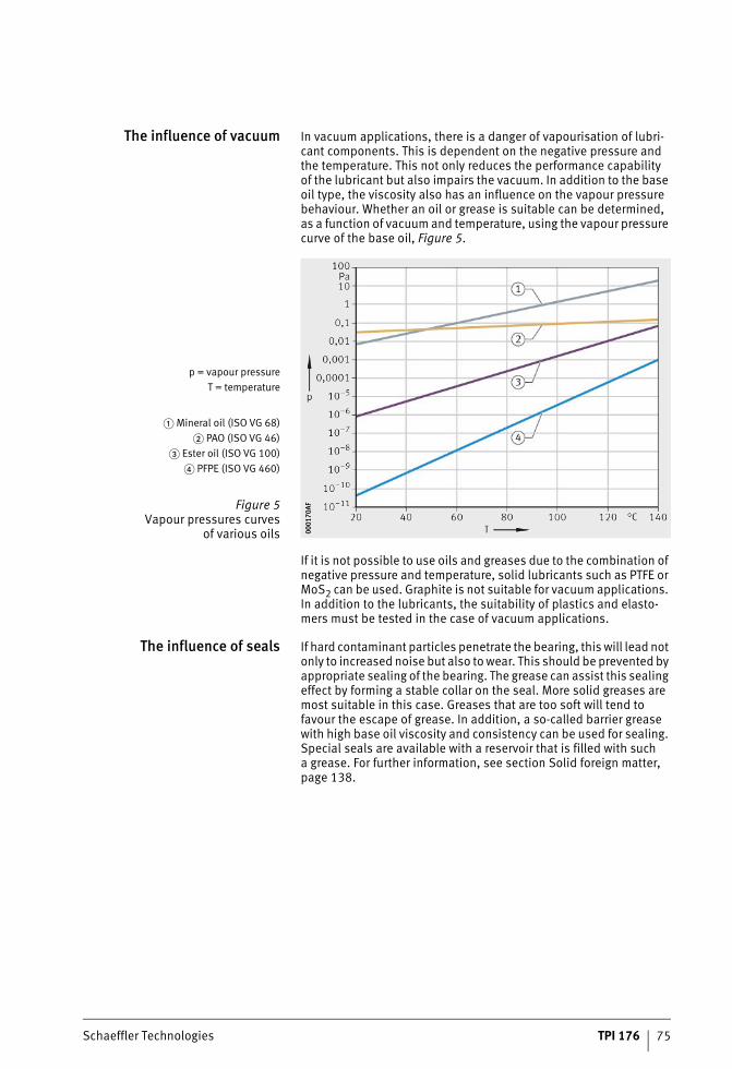
Schaeffler Technologies TPI 176 75
The influence of vacuum In vacuum applications, there is a danger of vapourisation of lubri-cant components. This is dependent on the negative pressure and the temperature. This not only reduces the performance capability of the lubricant but also impairs the vacuum. In addition to the base oil type, the viscosity also has an influence on the vapour pressure behaviour. Whether an oil or grease is suitable can be determined, as a function of vacuum and temperature, using the vapour pressure curve of the base oil, Figure 5.
If it is not possible to use oils and greases due to the combination of negative pressure and temperature, solid lubricants such as PTFE or MoS2 can be used. Graphite is not suitable for vacuum applications. In addition to the lubricants, the suitability of plastics and elasto-mers must be tested in the case of vacuum applications.
The influence of seals If hard contaminant particles penetrate the bearing, this will lead not only to increased noise but also to wear. This should be prevented by appropriate sealing of the bearing. The grease can assist this sealing effect by forming a stable collar on the seal. More solid greases are most suitable in this case. Greases that are too soft will tend to favour the escape of grease. In addition, a so-called barrier grease with high base oil viscosity and consistency can be used for sealing. Special seals are available with a reservoir that is filled with such a grease. For further information, see section Solid foreign matter, page 138.
p = vapour pressureT = temperature
� Mineral oil (ISO VG 68)� PAO (ISO VG 46)
� Ester oil (ISO VG 100)� PFPE (ISO VG 460)
Figure 5Vapour pressures curves
of various oils 0001
70AF
0001
70AF
ST4_3466890763_schmierstoffaus.fm Seite 75 Donnerstag, 4. April 2013 10:24 10
76 TPI 176 Schaeffler Technologies
Lubricant selection
The influenceof mounting position and
adjacent components
Even where an axis of rotation is vertical or inclined, lubricant must remain at the lubrication point. In addition to appropriate seals, flowing away of the grease can be prevented by using a more viscous grease. If several lubrication points are located close together, unintentional contact can occur. Attention must therefore be paid to compatibility of the lubricants with each other. Where possible, the optimum solution is to use only one grease. It must be ensured that the lubricant is compatible with the cage and seal material. Particular attention must be paid to the use of greases based on synthetic oils. Incompatibility can lead to embrittlement or swelling, with eventual destruction of the plastic. Meaningful results can be obtained through the use of appropriate storage tests.
The influence of legal andenvironmental regulations
In the foodstuffs sector, the use of greases with appropriate author-isation is specified. A worldwide standard is approval in accordance with the NSF (National Sanitary Foundation) H1 or H2, listed in the so-called White Book™.A lubricant with the code H1 (Food Grade Lubricant) may be used where occasional, technically unavoidable contact with foodstuffs cannot be eliminated. This means that the grease must be non-toxic, rapidly broken down by the organism and neutral in terms of both odour and taste. Such lubricants frequently comprise aluminium complex soap thickeners and polyalphaolefins or medicinal white oils as a base oil. Recently, authorisation to H1 has been granted to greases with other thickener types such as PTFE or calcium sul-phonate complex soaps. H2 lubricants are intended for general use within the foodstuffs industry where no foodstuff contact occurs. Furthermore, there are lubricants that fulfil individual religious rules, such as Jewish (kosher) or Islamic (halal).Greases with biological degradability must be provided where the lubricant can pass directly into the environment, see section Lubricants with biological degradability, page 88.Greases must conform to the appropriate legal regulations relating to prohibited substances.
ST4_3466890763_schmierstoffaus.fm Seite 76 Donnerstag, 4. April 2013 10:24 10
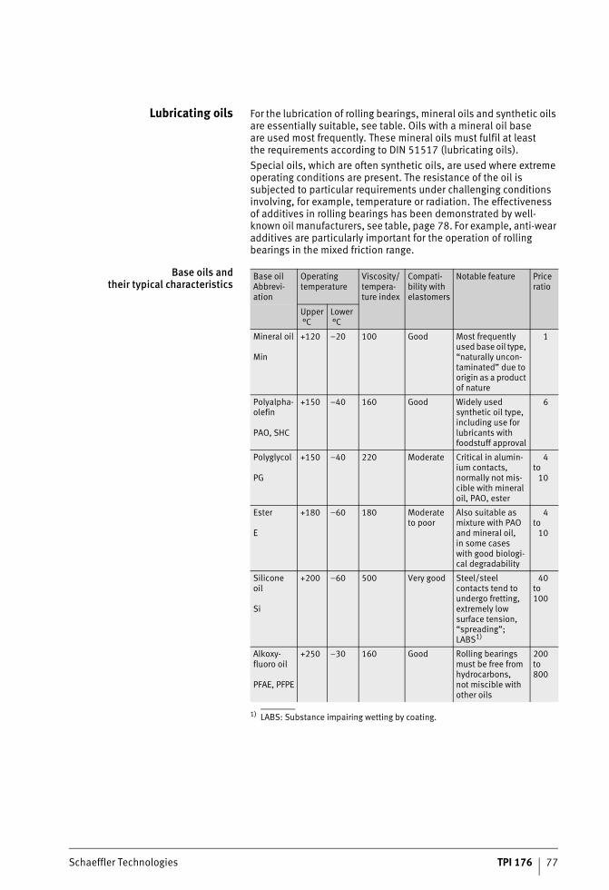
Schaeffler Technologies TPI 176 77
Lubricating oils For the lubrication of rolling bearings, mineral oils and synthetic oils are essentially suitable, see table. Oils with a mineral oil base are used most frequently. These mineral oils must fulfil at least the requirements according to DIN 51517 (lubricating oils).Special oils, which are often synthetic oils, are used where extreme operating conditions are present. The resistance of the oil is subjected to particular requirements under challenging conditions involving, for example, temperature or radiation. The effectiveness of additives in rolling bearings has been demonstrated by well-known oil manufacturers, see table, page 78. For example, anti-wear additives are particularly important for the operation of rolling bearings in the mixed friction range.
Base oils andtheir typical characteristics
1) LABS: Substance impairing wetting by coating.
Base oilAbbrevi-ation
Operating temperature
Viscosity/tempera-ture index
Compati-bility with elastomers
Notable feature Price ratio
Upper°C
Lower°C
Mineral oil
Min
+120 –20 100 Good Most frequently used base oil type, “naturally uncon-taminated” due to origin as a product of nature
1
Polyalpha-olefin
PAO, SHC
+150 –40 160 Good Widely used synthetic oil type, including use for lubricants with foodstuff approval
6
Polyglycol
PG
+150 –40 220 Moderate Critical in alumin-ium contacts, normally not mis-cible with mineral oil, PAO, ester
4to
10
Ester
E
+180 –60 180 Moderate to poor
Also suitable as mixture with PAO and mineral oil, in some cases with good biologi-cal degradability
4to
10
Silicone oil
Si
+200 –60 500 Very good Steel/steel contacts tend to undergo fretting, extremely low surface tension, “spreading”; LABS1)
40to100
Alkoxy-fluoro oil
PFAE, PFPE
+250 –30 160 Good Rolling bearings must be free from hydrocarbons, not miscible with other oils
200to800
ST4_3466890763_schmierstoffaus.fm Seite 77 Donnerstag, 4. April 2013 10:25 10
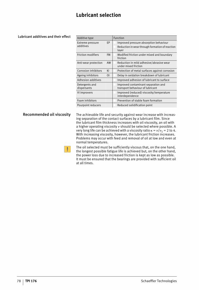
78 TPI 176 Schaeffler Technologies
Lubricant selection
Lubricant additives and their effect
Recommended oil viscosity The achievable life and security against wear increase with increas-ing separation of the contact surfaces by a lubricant film. Since the lubricant film thickness increases with oil viscosity, an oil with a higher operating viscosity � should be selected where possible. A very long life can be achieved with a viscosity ratio � = �/�1 = 2 to 4. With increasing viscosity, however, the lubricant friction increases. Problems may occur with feed and removal of oil at low and even at normal temperatures.The oil selected must be sufficiently viscous that, on the one hand, the longest possible fatigue life is achieved but, on the other hand, the power loss due to increased friction is kept as low as possible. It must be ensured that the bearings are provided with sufficient oil at all times.
Additive type Function
Extreme pressure additives
EP ■ Improved pressure absorption behaviour■ Reduction in wear through formation of reaction
layer
Friction modifiers FM ■ Modified friction under mixed and boundary friction
Anti-wear protection AW ■ Reduction in mild adhesive/abrasive wear under mixed friction
Corrosion inhibitors KI ■ Protection of metal surfaces against corrosion
Ageing inhibitors OI ■ Delay in oxidation breakdown of lubricant
Adhesion additives ■ Improved adhesion of lubricant to surface
Detergents anddispersants
■ Improved contaminant separation and transport behaviour of lubricant
VI improvers ■ Improved (reduced) viscosity/temperature interdependence
Foam inhibitors ■ Prevention of stable foam formation
Pourpoint reducers ■ Reduced solidification point
ST4_3466890763_schmierstoffaus.fm Seite 78 Donnerstag, 4. April 2013 10:25 10
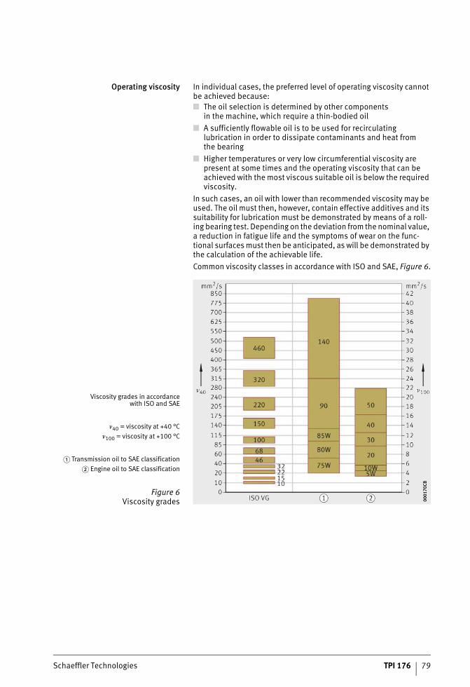
Schaeffler Technologies TPI 176 79
Operating viscosity In individual cases, the preferred level of operating viscosity cannot be achieved because:■ The oil selection is determined by other components
in the machine, which require a thin-bodied oil■ A sufficiently flowable oil is to be used for recirculating
lubrication in order to dissipate contaminants and heat from the bearing
■ Higher temperatures or very low circumferential viscosity are present at some times and the operating viscosity that can be achieved with the most viscous suitable oil is below the required viscosity.
In such cases, an oil with lower than recommended viscosity may be used. The oil must then, however, contain effective additives and its suitability for lubrication must be demonstrated by means of a roll-ing bearing test. Depending on the deviation from the nominal value, a reduction in fatigue life and the symptoms of wear on the func-tional surfaces must then be anticipated, as will be demonstrated by the calculation of the achievable life.Common viscosity classes in accordance with ISO and SAE, Figure 6.
Viscosity grades in accordancewith ISO and SAE
�40 = viscosity at +40 °C�100 = viscosity at +100 °C
� Transmission oil to SAE classification� Engine oil to SAE classification
Figure 6Viscosity grades 00
0170
CB00
0170
CB
ST4_3466890763_schmierstoffaus.fm Seite 79 Donnerstag, 4. April 2013 10:25 10
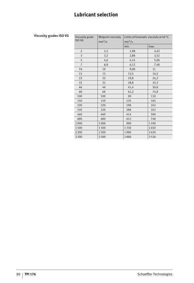
80 TPI 176 Schaeffler Technologies
Lubricant selection
Viscosity grades ISO VG Viscosity grade ISO VG
Midpoint viscosity Limits of kinematic viscosity at 40 °C
mm2/s mm2/s
min. max.
2 2,2 1,98 2,42
3 3,2 2,88 3,52
5 4,6 4,14 5,06
7 6,8 6,12 7,48
10 10 9,00 11
15 15 13,5 16,5
22 22 19,8 24,2
32 32 28,8 35,2
46 46 41,4 50,6
68 68 61,2 74,8
100 100 90 110
150 150 135 165
220 220 198 242
320 320 288 352
460 460 414 506
680 680 612 748
1 000 1 000 900 1 100
1 500 1 500 1 350 1 650
2 200 2 200 1 980 2 420
3 200 3 200 2 880 3 520
ST4_3466890763_schmierstoffaus.fm Seite 80 Donnerstag, 4. April 2013 10:25 10
Schaeffler Technologies TPI 176 81
Selection of oil in accordancewith operating conditions
In order to select the correct oil for the specific application, the operating conditions must first be analysed precisely.
Normal operating conditions Under normal operating conditions (atmospheric pressure, tempera-ture max. +100 °C in oil sump lubrication and +150 °C in recircu-lating oil lubrication, load ratio C/P � 10, speed up to permissible speed), undoped oils but preferably oils with inhibitors (anti-corrosion and anti-ageing, code L in accordance with DIN 51502) can be used. If the stated viscosity recommendations cannot be fulfilled, oils with effective anti-wear additives must be provided.
High speed parameters An oxidation-resistant oil with low foaming tendency and a favourable viscosity/temperature behaviour (V/T behaviour)is advantageous if high circumferential speeds are present (kf · n · dM � 500 000 min–1 · mm). Suitable synthetic oils withgood V/T behaviour include esters and polyalphaolefins (PAO),since the viscosity of these oils decreases less sharply with increasing temperature. In the starup phase, when the temperature is normally low, this avoids high splashing friction and thus heating; at the higher equilibrium temperature, there is still sufficient viscosity present to ensure lubrication.
High loads If the bearings are subjected to high loads (C/P � 10) or the operating viscosity � is lower than the reference viscosity �1, oils with anti-wear additives should be used (code P in accordance with DIN 51502).Anti-wear additives reduce the harmful effects of metallic contact occurring at various points. The suitability of anti-wear additives varies and is normally heavily dependent on temperature. Their effectiveness can only be assessed by means of testing in the rolling bearing (for example test rig FE 8).
High temperature In the case of oils for high operating temperatures, not only the oper-ating temperature limit but also the viscosity/temperature behaviour is particularly important. This behaviour can be assessed using so-called V/T diagrams, which are made available individually by the lubricant manufacturers. Selection should be made on the basis of the oil characteristics.
ST4_3466890763_schmierstoffaus.fm Seite 81 Donnerstag, 4. April 2013 10:25 10
82 TPI 176 Schaeffler Technologies
Lubricant selection
Selection of oil in accordancewith oil characteristics
The different types of oil have particular characteristics. On the basis of these characteristics, the most suitable oil can be selected.
Mineral oils Mineral oils can only be used up to +120 °C. Depending on the tem-perature and dwell time in the hot range, ageing products are formed that impair the lubrication effect and are deposited as solid residues (oil carbon) in the bearing or vicinity of the bearing.
Esters (diesters andsterically hindered esters)
Esters are thermally stable (–60 °C to +180 °C), have a favourable V/T behaviour, show low volatility and are therefore highly suitable for use at high speed parameters and high temperature. They are normally miscible with mineral oils. In the presence of water, esters undergo various reactions depending on their type. Some types saponify and break down into their components, which is mainly the case if they contain alkaline additives.
Poly (alkylene) glycols Poly(alkylene) glycols have a favourable V/T behaviour and are suitable for use at high and low temperatures (–40 °C to +150 °C). They are for the most part not water-soluble and cannot be mixed at all with mineral oils, have a lower pressure/viscosity coefficient than other oils and can attack seals and coatings in the housing as well as cages, such as those made from aluminium. Due to their high oxidation resistance, it is possible to increase the oil change intervals in high temperature operation to between 2 and 5 times the intervals normally used with mineral oil.
Polyalphaolefins (PAO) Polyalphaolefins are synthetically produced hydrocarbon com-pounds (also known as SHC for Synthetic Hydro Carbon). They have a favourable V/T behaviour, can be used over a wide temperature range (–50 °C to +150 °C) and have good oxidation resistance, which means they can achieve a lifetime several times longer compared to similarly viscous mineral oils under the same conditions. They are also miscible in any ratio with mineral oils.
Silicone oils(phenyl methyl siloxane)
Silicone oils can be used at extreme temperatures (–60° to +200 °C), have a favourable V/T behaviour, low volatility and high thermal stability. They have low load carrying capacity (C/P � 30) and low anti-wear capability.
ST4_3466890763_schmierstoffaus.fm Seite 82 Donnerstag, 4. April 2013 10:25 10
Schaeffler Technologies TPI 176 83
Alkoxyfluoro oils Alkoxy fluoro oils are resistant to oxidation and water, are very expensive in comparison with mineral oil products, have a higher pressure/viscosity coefficient and a higher density than mineral oils of the same viscosity. Their operating temperature range extends from –30 °C to +250 °C.When changing to another oil type, attention must be paid to compatibility, see section Miscibility of lubricants, page 130. In gen-eral, a change to an oil with lower performance capability should not be made.
Fire resistant hydraulic fluids Fire resistant hydraulic fluids occupy a special category. For reasons of safety, they have been used for many years in underground work-ings in mining, on ships, in aircraft and industrial plant with a fire risk. The reasons for their increasing include fire safety, availability and price.Fire resistant hydraulic fluids must fulfil defined requirements in relation to fire resistance, occupational hygiene and ecological compatibility. The various fluid groups are defined in the 7th Luxem-bourg Report, see table Fire resistant hydraulic fluids, page 86.
Compatibility with elastomers Where fire resistant pressure fluids act on hose or seal materials, physical or chemical interactions may occur. These can lead to changes in the volume, strength or elasticity characteristics of plas-tics (cages, sealing shields) and elastomers. If manufacturers’ data are not available, resistance investigations should be carried out before they are used. The test methods and criteria described in the 6th and 7th Luxembourg Report or in CETOP RP 81 H are to be taken as authoritative here. In these tests, defined test speciments are stored in the fluid to be tested for 168 hours at temperatures from +60 °C to +100 °C.
Application examples The fluid types HFA-E and HFA-S with up to 99 vol. % water are predominantly used in chemical plant, hydraulic presses and in hydraulic mine face supports.Fluids of type HFC with up to 45 vol. % water are normally used in processing machines such as hydraulic loaders, hammer drills and printing machinery.The synthetic HFD fluids are used in stage loaders, cableway machines, belt conveyors, hydrostatic couplings, pumps and in printing machinery.
ST4_3466890763_schmierstoffaus.fm Seite 83 Donnerstag, 4. April 2013 10:25 10
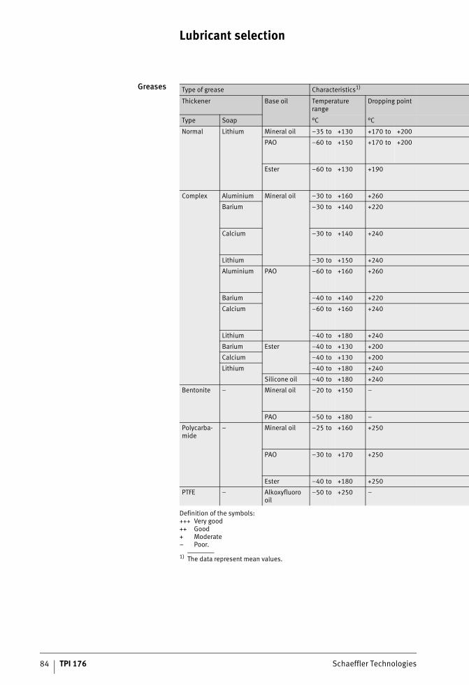
Lubricant selection
84 TPI 176 Schaeffler Technologies
Greases
1) The data represent mean values.
Type of grease Characteristics1)
Thickener Base oil Temperature range
Dropping point
Type Soap °C °C
Normal Lithium Mineral oil –35 to +130 +170 to +200
PAO –60 to +150 +170 to +200
Ester –60 to +130 +190
Complex Aluminium Mineral oil –30 to +160 +260
Barium –30 to +140 +220
Calcium –30 to +140 +240
Lithium –30 to +150 +240
Aluminium PAO –60 to +160 +260
Barium –40 to +140 +220
Calcium –60 to +160 +240
Lithium –40 to +180 +240
Barium Ester –40 to +130 +200
Calcium –40 to +130 +200
Lithium –40 to +180 +240
Silicone oil –40 to +180 +240
Bentonite – Mineral oil –20 to +150 –
PAO –50 to +180 –
Polycarba-mide
– Mineral oil –25 to +160 +250
PAO –30 to +170 +250
Ester –40 to +180 +250
PTFE – Alkoxyfluoro oil
–50 to +250 –
Definition of the symbols:+++ Very good++ Good+ Moderate– Poor.
ST4_3466890763_schmierstoffaus.fm Seite 84 Donnerstag, 4. April 2013 10:25 10
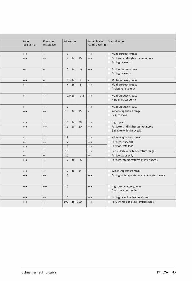
Schaeffler Technologies TPI 176 85
Water resistance
Pressure resistance
Price ratio Suitability for rolling bearings
Special notes
+++ + 1 +++ ■ Multi-purpose grease
+++ ++ 4 to 10 +++ ■ For lower and higher temperatures■ For high speeds
++ + 5 to 6 +++ ■ For low temperatures■ For high speeds
+++ + 2,5 to 4 + ■ Multi-purpose grease
++ ++ 4 to 5 +++ ■ Multi-purpose grease■ Resistant to vapour
++ ++ 0,9 to 1,2 +++ ■ Multi-purpose grease■ Hardening tendency
++ ++ 2 +++ ■ Multi-purpose grease
+++ ++ 10 to 15 + ■ Wide temperature range■ Easy to move
+++ +++ 15 to 20 +++ ■ High speed
+++ +++ 15 to 20 +++ ■ For lower and higher temperatures■ Suitable for high speeds
++ +++ 15 +++ ■ Wide temperature range
++ ++ 7 +++ ■ For higher speeds■ For moderate load+++ ++ 7 +++
++ + 10 +++ ■ Particularly wide temperature range
++ – 20 ++ ■ For low loads only
+++ + 2 to 6 + ■ For higher temperatures at low speeds
+++ + 12 to 15 + ■ Wide temperature range
+++ ++ 3 +++ ■ For higher temperatures at moderate speeds
+++ +++ 10 +++ ■ High temperature grease■ Good long term action
+++ ++ 10 +++ ■ For high and low temperatures
+++ ++ 100 to 150 +++ ■ For very high and low temperatures
ST4_3466890763_schmierstoffaus.fm Seite 85 Donnerstag, 4. April 2013 10:25 10
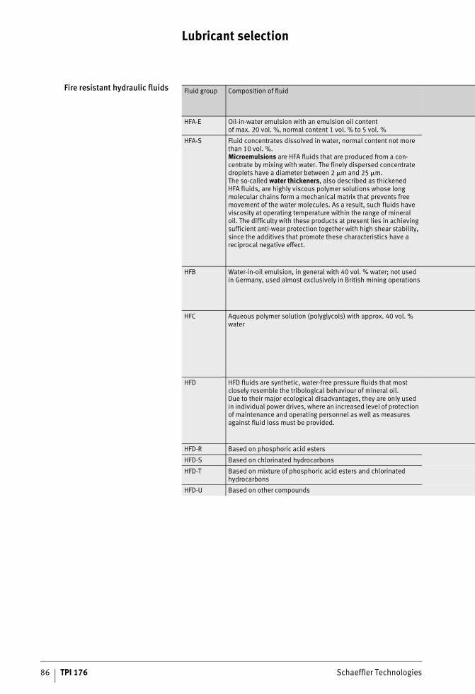
Lubricant selection
86 TPI 176 Schaeffler Technologies
Fire resistant hydraulic fluids Fluid group Composition of fluid
HFA-E Oil-in-water emulsion with an emulsion oil content of max. 20 vol. %, normal content 1 vol. % to 5 vol. %
HFA-S Fluid concentrates dissolved in water, normal content not more than 10 vol. %.Microemulsions are HFA fluids that are produced from a con-centrate by mixing with water. The finely dispersed concentrate droplets have a diameter between 2 �m and 25 �m.The so-called water thickeners, also described as thickened HFA fluids, are highly viscous polymer solutions whose long molecular chains form a mechanical matrix that prevents free movement of the water molecules. As a result, such fluids have viscosity at operating temperature within the range of mineral oil. The difficulty with these products at present lies in achieving sufficient anti-wear protection together with high shear stability, since the additives that promote these characteristics have a reciprocal negative effect.
HFB Water-in-oil emulsion, in general with 40 vol. % water; not used in Germany, used almost exclusively in British mining operations
HFC Aqueous polymer solution (polyglycols) with approx. 40 vol. % water
HFD HFD fluids are synthetic, water-free pressure fluids that most closely resemble the tribological behaviour of mineral oil. Due to their major ecological disadvantages, they are only used in individual power drives, where an increased level of protection of maintenance and operating personnel as well as measures against fluid loss must be provided.
HFD-R Based on phosphoric acid esters
HFD-S Based on chlorinated hydrocarbons
HFD-T Based on mixture of phosphoric acid esters and chlorinated hydrocarbons
HFD-U Based on other compounds
ST4_3466890763_schmierstoffaus.fm Seite 86 Donnerstag, 4. April 2013 10:25 10

Schaeffler Technologies TPI 176 87
ISO VG grade Normal operating temperature range
Fire resistance DensityT = 15 °C
Standards and specifications
°C g/cm3
Not defined +5 to +55 Very good Approx. 1 DIN 24320
32 +5 to +60 Good 0,92 to 1,05 VDMA 24317
46
68
100
15 –20 to +60 Very good 1,04 to 1,09
22
32
46
68
100
15 –20 to +150 Good 1,1 to 1,45
22
32
46
68
100
ST4_3466890763_schmierstoffaus.fm Seite 87 Donnerstag, 4. April 2013 10:25 10
88 TPI 176 Schaeffler Technologies
Special applications
Lubricantswith biological degradability
Lubricants with biological degradability must be used in preference or specified where the lubricant can pass directly into the environ-ment. This is the case, for example, in agricultural equipment applications, railway switch points, in treatment plants or sluices with loss lubrication. However, there are no universally recognised directives here and regulations and laws are often only valid locally.Biological degradability of oils is increasingly determined in accordance with OECD 301 A-F. For type K greases in accordance with DIN 51821, CEC-L-33-T-82 or the so-called Zahn-Wellen test is applied. In this case, the lubricant must exhibit biological degradation of at least 60% (OECD) or 80% (CEC) after 21 days. In addition, an environmentally friendly lubricant must conform in terms of component toxicity to the German Chemicals Act and the water pollution hazard class (WGK). This information can be found in the safety data sheet of the lubricant.
Restricted temperature range Lubricants based on vegetable oils and mixtures of such oils with inter-esterified products are only suitable for a restricted tempera-ture range and low to normal loads for simple subassemblies with relubrication. If central lubrication systems are used, their suitability must be checked.Greases based on synthetic oils, predominantly ester oils, have in contrast a performance capacity of around the same level as normal greases. Attention must be paid to the resistance of any plastics used.
Ceramic and hybrid bearings In comparison with steel, ceramics have a lower specific mass, higher heat resistance, lower thermal expansion, good chemical resistance, higher rigidity, high specific heat capacity, lower thermal conductivity and are also antimagnetic and electrically insulating.The ceramic material used in rolling bearings is hot pressed silicon nitride (Si3N4). This is used predominantly for the rolling elements. The associated rings are made, depending on the application, from various steels. In combination with special steels, such rolling bearings have particular resistance to corrosion, achieve increased fatigue life under unfavourable lubrication conditions and are significantly less sensitive to wear if there is inadequate separation of the contact surfaces.
ST4_3468224011_sonderanwendung.fm Seite 88 Donnerstag, 4. April 2013 10:26 10
Schaeffler Technologies TPI 176 89
Lower strain on lubricant Under identical loads, rolling bearings with ceramic rolling elements have higher contact pressures but significantly smaller contact sur-faces than in conventional rolling bearings. These are significantly easier to supply with lubricant and, due to the smaller deformation, have significantly smaller proportions of sliding motion. Despite the higher pressure, the strain placed on the lubricant is thus lower and, especially in the case of grease lubrication, a significant increase in operating life is achieved. The smaller contact surfaces and the more favourable sliding characteristics lead to lower friction and, as a result, to lower temperatures. The preferred areas of use are rolling bearings at very high speeds in a wide temperature range as well as rolling bearings that must achieve very long running times with grease lubrication, and bearings under other extreme operating conditions.Depending on the application, various lubricants are required for the lubrication of such hybrid bearings (steel rings and ceramic rolling elements). Hybrid bearings used in aircraft engines are lubri-cated using approved ester oils.
Hybrid spindle bearings Hybrid spindle bearings are also used very widely and are made available in some cases with seals and greasing. For grease-lubricated spindle bearings, greases with ester base oils and special additives are used. In general, strongly polar oils with additives matched to the steel/ceramic material pair are necessary.In tests with spindle bearings, the use of hybrid spindle bearings has made it possible to achieve a lubrication interval or grease operating life that is longer by a factor of 2 to 3.
Full ceramic bearings Full ceramic bearings are used only rarely. While the demands on the lubricant are low, mounting of these bearings is a considerable technical challenge. Due to the different thermal expansion and the high sensitivity to tensile stresses, it is difficult to achieve location of the bearings on shafts and in housings. Furthermore, the high price restricts their use to those cases where it is absolutely necessary.
ST4_3468224011_sonderanwendung.fm Seite 89 Donnerstag, 4. April 2013 10:26 10
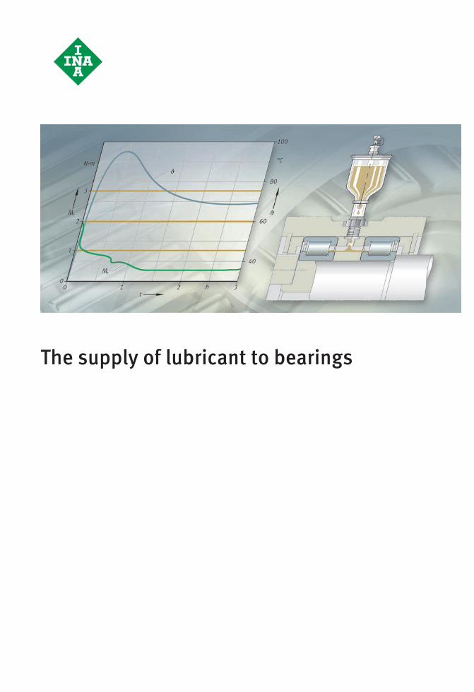
The supply of lubricant to bearings
#tpi176__en_gb__de.xml_FM8_en_gb.book Seite 90 Donnerstag, 4. April 2013 8:22 08
Schaeffler Technologies TPI 176 91
Page
The supply of lubricant to bearings
The supplyof lubricant to bearings
The supply of grease ............................................................... 92Initial greasing and new greasing........................................ 92Grease operating life .......................................................... 95Relubrication interval ......................................................... 102Relubrication and relubrication intervals............................. 103Special types of relubrication ............................................. 103Arcanol rolling bearing greases........................................... 105Examples of grease lubrication ........................................... 106
The supply of oil ..................................................................... 112Oil bath lubrication ............................................................ 112Recirculating lubrication..................................................... 114Minimal quantity lubrication............................................... 119Examples of oil lubrication ................................................. 123
Miscibilityof lubricants
Miscibility of greases and oils ................................................. 130
Checking of miscibility ............................................................ 132
Lubrication systems andmonitoring
Lever grease gun..................................................................... 133
Motion Guard.......................................................................... 133
Condition monitoring .............................................................. 134
ST4_3561572619_ivz.fm Seite 91 Donnerstag, 4. April 2013 10:26 10
92 TPI 176 Schaeffler Technologies
The supply of lubricant to bearings
The lubricant quantity actually required by a rolling bearing is extraordinarily small. Due to the operational reliability of the bearing arrangement, however, it is normally estimated at a higher valuein practice. However, too much lubricant in the bearing can lead to damage. If excess lubricant cannot escape, the splashing or churning work will lead to temperatures at which the lubricant may be impaired or even destroyed.In general, an adequate supply is ensured through the following:■ selection of the correct lubricant quantity and distribution in
the bearing■ attention to the operating life of the lubricant■ appropriate addition of lubricant or lubricant replacement■ targeted design of the bearing position■ the necessary devices and lubrication method, see table,
page 60.
The supply of grease In the case of grease lubrication, little or no work on devices is normally required in order to lubricate the bearings adequately.If the bearings fitted do not have an initial greasing carried out bythe manufacturer, the bearings are frequently greased by handwhen they are mounted. In many cases, this is assisted by the use of injection syringes or grease guns.A selection of specific rolling bearing greases is shown in table Greases, page 126.
Initial greasing andnew greasing
In the greasing of bearings, the following guidelines must be observed:■ Fill the bearings such that all functional surfaces definitely
receive grease.■ Fill any housing cavity adjacent to the bearing with grease only
to the point where there is still sufficient space for the grease displaced from the bearing. This is intended to avoid co-rotation of the grease. If a large, unfilled housing cavity is adjacent tothe bearing, sealing shields or washers as well as baffle plates should be used to ensure that an appropriate grease quantity (similar to the quantity that is selected for the normal degree of filling) remains in the vicinity of the bearing. A grease fillingof approx. 90% of the undisturbed free bearing volume is recommended. This is defined as the volume in the interior ofthe bearing that does not come into contact with rotating parts (rolling elements, cage).
ST4_3561650571_versorgung_der_.fm Seite 92 Donnerstag, 4. April 2013 10:26 10
Schaeffler Technologies TPI 176 93
■ In the case of bearings rotating at very high speeds, such as spindle bearings, a smaller grease quantity is generally selected (approx. 60% of the undisturbed free bearing volume or approx. 30% of the total free bearing volume), in order to aid grease distribution during starting of the bearings.
■ The sealing action of a gap seal is improved by the formation ofa stable grease collar. This effect is supported by continuous relubrication.
■ If the correct degree of filling is used, favourable friction behaviour and low grease loss will be achieved.
■ If there is a pressure differential between the two sides ofthe bearing, the flow of air may drive the grease and the released base oil out of the bearing and may also carry contaminationinto the bearing. In such cases, pressure balancing is required by means of openings and holes in the adjacent parts.
■ Bearing rotating at low speeds (n · dM � 50 000 min–1 · mm) and their housings must be filled completely with grease.The churning friction occurring in this case is negligible. It is important that the grease introduced is held in the bearing or vicinity of the bearing by the seals and baffle plates. The reservoir effect of grease in the vicinity of the bearing leads to an increase in the lubrication interval. However, this is conditional on direct contact with the grease in the bearing (grease bridge). Occasional shaking will also lead to fresh grease moving intothe bearing from its environment (internal relubrication).
■ If a high temperature is expected in the bearing, the appropriate grease should be supplemented by a grease reservoir that hasa surface as large as possible facing the bearing and that dispenses oil. The favourable quantity for the reservoir is two to three times the normal degree of filling. The reservoir must be provided either on one side of the bearing or preferably to an identical extent on both sides.
ST4_3561650571_versorgung_der_.fm Seite 93 Donnerstag, 4. April 2013 10:26 10
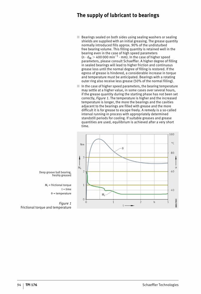
94 TPI 176 Schaeffler Technologies
The supply of lubricant to bearings
■ Bearings sealed on both sides using sealing washers or sealing shields are supplied with an initial greasing. The grease quantity normally introduced fills approx. 90% of the undisturbedfree bearing volume. This filling quantity is retained well in the bearing even in the case of high speed parameters (n · dM � 400 000 min–1 · mm). In the case of higher speed parameters, please consult Schaeffler. A higher degree of filling in sealed bearings will lead to higher friction and continuous grease loss until the normal degree of filling is restored. If the egress of grease is hindered, a considerable increase in torque and temperature must be anticipated. Bearings with a rotating outer ring also receive less grease (50% of the normal filling).
■ In the case of higher speed parameters, the bearing temperature may settle at a higher value, in some cases over several hours,if the grease quantity during the starting phase has not been set correctly, Figure 1. The temperature is higher and the increased temperature is longer, the more the bearings and the cavities adjacent to the bearings are filled with grease and the more difficult it is for grease to escape freely. A remedy is a so-called interval running-in process with appropriately determined standstill periods for cooling. If suitable greases and grease quantities are used, equilibrium is achieved after a very short time.
Deep groove ball bearing,freshly greased
Mr = frictional torquet = time
� = temperature
Figure 1Frictional torque and temperature 00
0170
CC00
0170
CC
ST4_3561650571_versorgung_der_.fm Seite 94 Donnerstag, 4. April 2013 10:26 10
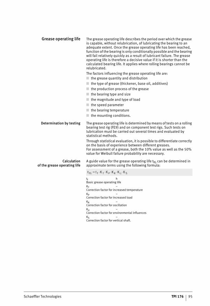
Schaeffler Technologies TPI 176 95
Grease operating life The grease operating life describes the period over which the grease is capable, without relubrication, of lubricating the bearing to an adequate extent. Once the grease operating life has been reached, function of the bearing is only conditionally possible and the bearing will fail relatively quickly as a result of lubricant failure. The grease operating life is therefore a decisive value if it is shorter than the calculated bearing life. It applies where rolling bearings cannot be relubricated.The factors influencing the grease operating life are:■ the grease quantity and distribution■ the type of grease (thickener, base oil, additives)■ the production process of the grease■ the bearing type and size■ the magnitude and type of load■ the speed parameter■ the bearing temperature■ the mounting conditions.
Determination by testing The grease operating life is determined by means of tests on a rolling bearing test rig (FE9) and on component test rigs. Such tests on lubrication must be carried out several times and evaluated by statistical methods.Through statistical evaluation, it is possible to differentiate correctly on the basis of experience between different greases.For assessment of a grease, both the 10% value as well as the 50% value for Weibull failure probability are necessary.
Calculationof the grease operating life
A guide value for the grease operating life tfG can be determined in approximate terms using the following formula:
tf hBasic grease operating lifeKT –Correction factor for increased temperatureKP –Correction factor for increased loadKR –Correction factor for oscillationKU –Correction factor for environmental influencesKS –Correction factor for vertical shaft.
ST4_3561650571_versorgung_der_.fm Seite 95 Donnerstag, 4. April 2013 10:27 10
96 TPI 176 Schaeffler Technologies
The supply of lubricant to bearings
The values determined are guide values only, since the determi-nation is based on statistical principles. It is assumed that operating conditions are constant and that a suitable lubricant is presentin a sufficient quantity. This is rarely the case in practice. As a result, the calculation model cannot supply precise values and almost no account is taken of other influences such as thermal conduction or contaminants.Guidelines on calculating the grease operating life:■ In the case of combined bearings, the radial bearing and
axial bearing must be calculated separately. The shorter grease operating life is then taken as the defining value.
■ If the outer ring rotates, there may be a reduction in the grease operating life.
■ In the case of yoke and stud type track rollers, angular defects may occur. The effect of the rotating outer ring is already taken into consideration in the bearing type factor kf.
The grease operating life cannot be determined using the method described in the following cases:■ The grease can flow out of the rolling bearing
– there is excessive vapourisation of the base oil– the bearing is not sealed– the axial bearing has a horizontal axis of rotation
■ Air is sucked through the rolling bearing during operation– risk of increased grease oxidation
■ Combined rotary and linear motion is present– the grease is distributed over the whole stroke length
■ Contamination, water or other fluids enter the bearings■ There is no type factor for the bearings.If the grease operating life is longer than 3 years, the lubricant manufacturer must be consulted.
ST4_3561650571_versorgung_der_.fm Seite 96 Donnerstag, 4. April 2013 10:27 10
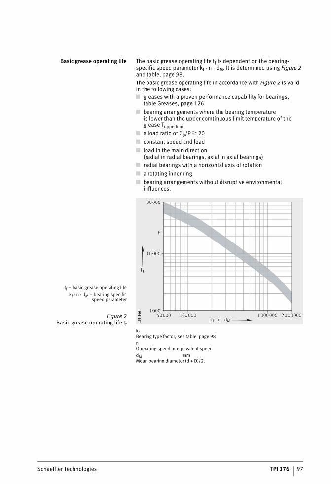
Schaeffler Technologies TPI 176 97
Basic grease operating life The basic grease operating life tf is dependent on the bearing-specific speed parameter kf · n · dM. It is determined using Figure 2 and table, page 98.The basic grease operating life in accordance with Figure 2 is validin the following cases:■ greases with a proven performance capability for bearings,
table Greases, page 126■ bearing arrangements where the bearing temperature
is lower than the upper comtinuous limit temperature of the grease Tupperlimit
■ a load ratio of C0/P � 20■ constant speed and load■ load in the main direction
(radial in radial bearings, axial in axial bearings)■ radial bearings with a horizontal axis of rotation■ a rotating inner ring■ bearing arrangements without disruptive environmental
influences.
kf –Bearing type factor, see table, page 98nOperating speed or equivalent speeddM mmMean bearing diameter (d + D)/2.
tf = basic grease operating lifekf · n · dM = bearing-specific
speed parameter
Figure 2Basic grease operating life tf
155
246
155
246
ST4_3561650571_versorgung_der_.fm Seite 97 Donnerstag, 4. April 2013 10:27 10
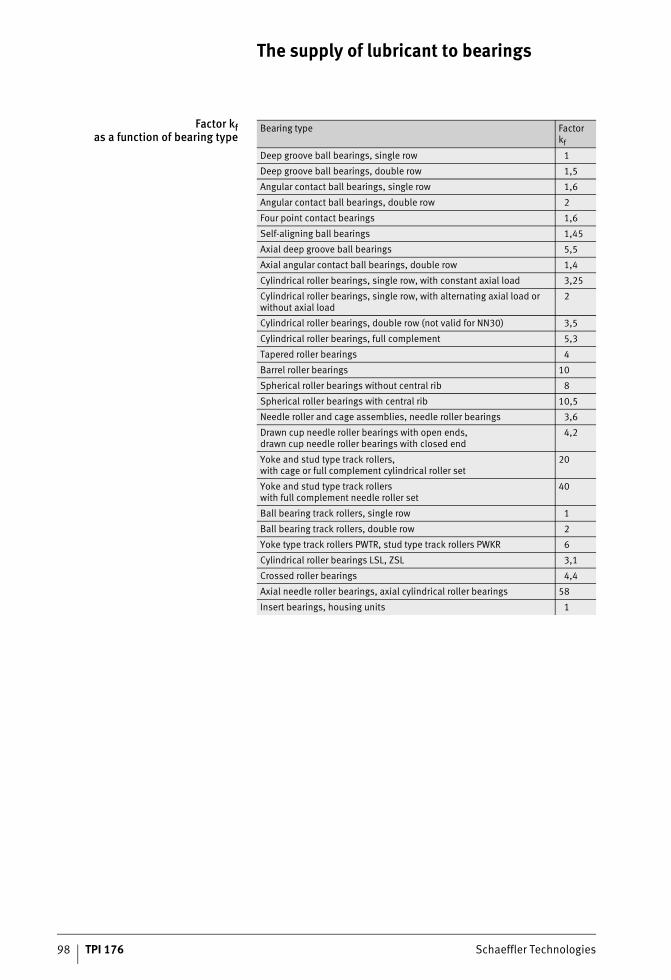
98 TPI 176 Schaeffler Technologies
The supply of lubricant to bearings
Factor kfas a function of bearing type
Bearing type Factorkf
Deep groove ball bearings, single row 1
Deep groove ball bearings, double row 1,5
Angular contact ball bearings, single row 1,6
Angular contact ball bearings, double row 2
Four point contact bearings 1,6
Self-aligning ball bearings 1,45
Axial deep groove ball bearings 5,5
Axial angular contact ball bearings, double row 1,4
Cylindrical roller bearings, single row, with constant axial load 3,25
Cylindrical roller bearings, single row, with alternating axial load or without axial load
2
Cylindrical roller bearings, double row (not valid for NN30) 3,5
Cylindrical roller bearings, full complement 5,3
Tapered roller bearings 4
Barrel roller bearings 10
Spherical roller bearings without central rib 8
Spherical roller bearings with central rib 10,5
Needle roller and cage assemblies, needle roller bearings 3,6
Drawn cup needle roller bearings with open ends,drawn cup needle roller bearings with closed end
4,2
Yoke and stud type track rollers,with cage or full complement cylindrical roller set
20
Yoke and stud type track rollerswith full complement needle roller set
40
Ball bearing track rollers, single row 1
Ball bearing track rollers, double row 2
Yoke type track rollers PWTR, stud type track rollers PWKR 6
Cylindrical roller bearings LSL, ZSL 3,1
Crossed roller bearings 4,4
Axial needle roller bearings, axial cylindrical roller bearings 58
Insert bearings, housing units 1
ST4_3561650571_versorgung_der_.fm Seite 98 Donnerstag, 4. April 2013 10:28 10
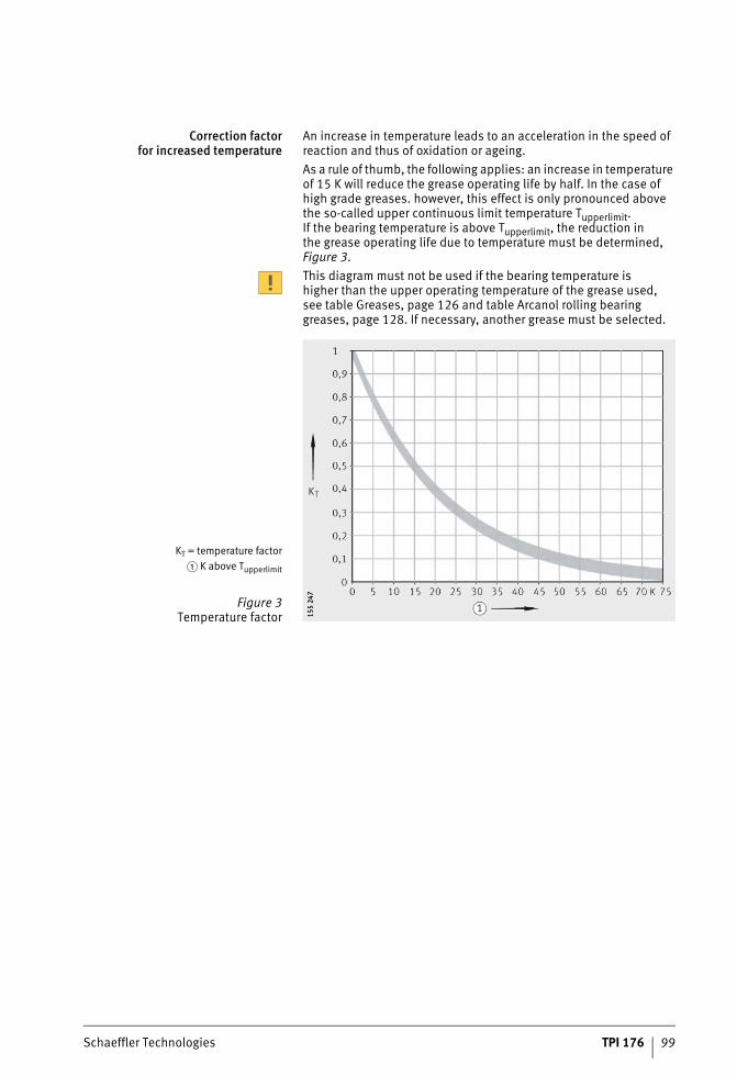
Schaeffler Technologies TPI 176 99
Correction factorfor increased temperature
An increase in temperature leads to an acceleration in the speed of reaction and thus of oxidation or ageing.As a rule of thumb, the following applies: an increase in temperature of 15 K will reduce the grease operating life by half. In the case of high grade greases. however, this effect is only pronounced above the so-called upper continuous limit temperature Tupperlimit.If the bearing temperature is above Tupperlimit, the reduction inthe grease operating life due to temperature must be determined, Figure 3.This diagram must not be used if the bearing temperature ishigher than the upper operating temperature of the grease used,see table Greases, page 126 and table Arcanol rolling bearing greases, page 128. If necessary, another grease must be selected.
KT = temperature factor� K above Tupperlimit
Figure 3Temperature factor 15
5 24
715
5 24
7
ST4_3561650571_versorgung_der_.fm Seite 99 Donnerstag, 4. April 2013 10:28 10
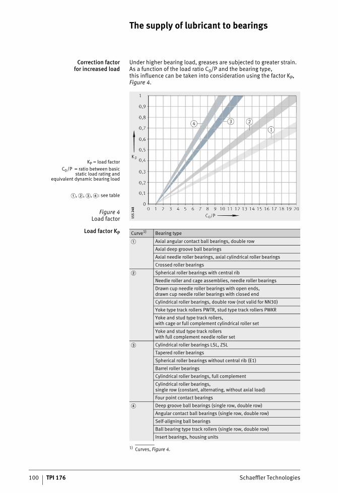
100 TPI 176 Schaeffler Technologies
The supply of lubricant to bearings
Correction factorfor increased load
Under higher bearing load, greases are subjected to greater strain. As a function of the load ratio C0/P and the bearing type,this influence can be taken into consideration using the factor KP, Figure 4.
Load factor KP
1) Curves, Figure 4.
KP = load factorC0/P = ratio between basic
static load rating andequivalent dynamic bearing load
�, �, �, �: see table
Figure 4Load factor 15
5 24
815
5 24
8
Curve1) Bearing type
� Axial angular contact ball bearings, double row
Axial deep groove ball bearings
Axial needle roller bearings, axial cylindrical roller bearings
Crossed roller bearings
� Spherical roller bearings with central rib
Needle roller and cage assemblies, needle roller bearings
Drawn cup needle roller bearings with open ends,drawn cup needle roller bearings with closed end
Cylindrical roller bearings, double row (not valid for NN30)
Yoke type track rollers PWTR, stud type track rollers PWKR
Yoke and stud type track rollers,with cage or full complement cylindrical roller set
Yoke and stud type track rollerswith full complement needle roller set
� Cylindrical roller bearings LSL, ZSL
Tapered roller bearings
Spherical roller bearings without central rib (E1)
Barrel roller bearings
Cylindrical roller bearings, full complement
Cylindrical roller bearings,single row (constant, alternating, without axial load)
Four point contact bearings
� Deep groove ball bearings (single row, double row)
Angular contact ball bearings (single row, double row)
Self-aligning ball bearings
Ball bearing type track rollers (single row, double row)
Insert bearings, housing units
ST4_3561650571_versorgung_der_.fm Seite 100 Donnerstag, 4. April 2013 10:28 10
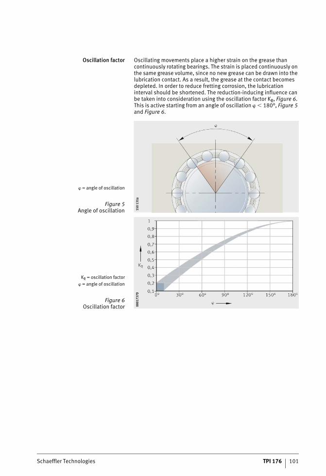
Schaeffler Technologies TPI 176 101
Oscillation factor Oscillating movements place a higher strain on the grease than continuously rotating bearings. The strain is placed continuously on the same grease volume, since no new grease can be drawn into the lubrication contact. As a result, the grease at the contact becomes depleted. In order to reduce fretting corrosion, the lubrication interval should be shortened. The reduction-inducing influence can be taken into consideration using the oscillation factor KR, Figure 6. This is active starting from an angle of oscillation � � 180°, Figure 5 and Figure 6.
� = angle of oscillation
Figure 5Angle of oscillation 15
0 13
1a15
0 13
1a
KR = oscillation factor� = angle of oscillation
Figure 6Oscillation factor 00
0173
7D00
0173
7D
ST4_3561650571_versorgung_der_.fm Seite 101 Donnerstag, 4. April 2013 10:28 10
102 TPI 176 Schaeffler Technologies
The supply of lubricant to bearings
Environment factor The factor KU takes account of the influences of moisture,shaking forces, slight vibration and shocks, see table Environment factor.It does not take account of extreme environmental influences such as water, aggressive media, contamination, nuclear radiation and extreme vibrations such as those occurring in vibratory machines.In relation to contamination, the influence of contamination on rating life calculation must also be noted, see section Load carrying capacity and rating life, page 18.
Environment factor
Factor for vertical shaft If increased escape of grease is expected, for example in the caseof radial bearings with a vertical axis of rotation, this influence must be taken into consideration using the factor KS, see table Factor.
Factor
Relubrication interval Where rolling bearings are suitable for relubrication, regular relubri-cation is recommended in order to ensure the reliable function ofthe bearings.Experience shows that, as a guide value, the relubrication interval tfR for most applications can be calculated as follows:
tfR hGuide value for relubrication intervaltfG hGuide value for grease operating life, see page 95.
Environmental influence Environment factorKU
Slight(for example, test rig)
1
Moderate(standard)
0,8
Heavy(for example, outdoor application)
0,5
Vertical shaft FactorKS
Vertical shaft(depending on sealing)
0,5 to 0,7
Otherwise 1
ST4_3561650571_versorgung_der_.fm Seite 102 Donnerstag, 4. April 2013 10:29 10
Schaeffler Technologies TPI 176 103
After this time, the grease in the bearing is used up to the extent that addition or replacement is necessary. Once the grease operating life is reached, the grease is in such a condition that it can no longer be simply pressed out of the bearing. For organisational andeconomic reasons, the lubrication intervals should be matched to the maintenance periods that are required in operational terms. Experience shows that relubrication intervals longer than one year should not be recommended, since they are frequently forgotten.Relubrication should also be carried out before and after extended periods without operation, in order to achieve anti-corrosion protection in the bearing and to facilitate restarting with fresh grease.The relubrication procedure should be carried out while the bearing is warm from operation and slowly rotating, in order to ensure good grease distribution. Old grease must be allowed to leave the bearing unhindered.
Relubrication andrelubrication intervals
Relubrication or a grease change is necessary if the grease operating life is shorter than the expected bearing life.Relubrication can be carried out as follows. Relubrication can often still be carried out using lever grease guns and lubrication nipples. Increasing importance is being attached to greasing systems such as the automatic lubricator Motion Guard and also central lubrication systems and grease spraying equipment. It is important thatthe used grease can be displaced by the new grease so that grease is replaced but overlubrication does not occur.
Special typesof relubrication
Under certain environmental and application conditions,or where required by the adjuacent construction, special types of relubrication are necessary.
Addition of grease Addition of grease should only be carried out if the used grease cannot be removed during relubrication (no free cavities in the housing, no grease outlet hole, no grease valve). The grease quantity supplied should be restricted in order to prevent overlubrication.
ST4_3561650571_versorgung_der_.fm Seite 103 Donnerstag, 4. April 2013 10:29 10
104 TPI 176 Schaeffler Technologies
The supply of lubricant to bearings
Increased relubrication Increased relubrication is necessary if there are large free cavitiesin the housing, grease regulators, grease outlet holes or grease valves are present or in the case of low speeds corresponding to n · dM � 100 000 min–1 · mm. In such cases, there is only a slight increase in temperature due to grease churning friction.Generous relubrication improves the replacement of used grease by fresh grease and supports sealing against dust and moisture.Where possible, relubrication should be carried out with the bearing warm from operation and rotating.
Grease replacement Where lubrication intervals are long, the aim should be to achieve grease replacement. Substantial replacement of used grease by fresh grease is achieved with the aid of a larger relubrication quantity. A large relubrication quantity is necessary principally if the used grease has already been damaged due to higher temperature. In order to remove as much used grease as possible by means ofthe "flushing effect", relubrication is carried out using a quantity that is up to three times as large as the normal relubrication quantity. Suitable greases can be recommended by lubricant manufacturers. A uniform supply of grease around the bearing circumference willaid grease replacement. Relevant design examples are shown in Figure 7, page 106 to Figure 14, page 111. The precondition for substantial replacement of used grease by fresh grease is thatthe used grease can escape freely or a sufficiently large cavity is made available for collection of the used grease.
Very short relubrication intervals Very short relubrication intervals (daily or even shorter) are applicable if extreme strains are present. In such cases, the use ofa grease pump or lubricators is justified.
Supportfor seals by escaping grease
The seals can be supported by escaping grease if relubrication is carried out using small quantities at short intervals.The relubrication quantity per hour can be between half and several times as large as the grease quantity that will fit in the free bearing interior.
Relubrication at high temperature At high temperature, grease lubrication is possible with economical grease that is stable for only short periods or with expensive grease that has good temperature stability. For the greases stable forshort periods, relubrication corresponding to 1% to 2% of the free bearing cavity per hour has proved effective for lubrication.In the case of greases with good temperature stability, significantly smaller relubrication quantities are sufficient.During relubrication, it must be ensured that there is no impermiss-ible mixing of lubricant, see section Miscibility of lubricants, page 130.
ST4_3561650571_versorgung_der_.fm Seite 104 Donnerstag, 4. April 2013 10:29 10
Schaeffler Technologies TPI 176 105
Arcanolrolling bearing greases
A selection of lubricants in various container sizes is included inthe Schaeffler range under the name Arcanol. Each of these greases is subjected to a comprehensive series of tests before it is accepted into the range. These are carried out not only in the lubricant laboratory but also and principally on test rigs, where the grease must demonstrate its suitability in various rolling bearing typesand under defined conditions.The greases are tested in rolling bearings in relation to operating life, friction behaviour and wear on the FE8 test rig (DIN 51819) andFE9 test rig (DIN 51821). If the results fulfil the requirements ofthe Schaeffler specifications, the grease is accepted into the Arcanol range.Each batch supplied of these greases is first tested in order to ensure uniform quality. It is only after the incoming goods testing has been completed successfully that approval is given to fill containers using the grease as Arcanol. The greases are sold via the Business Division Industrial Aftermarket of the Schaeffler Group. Technical data sheets and safety data sheets can be requested.The Arcanol grease range is graduated such that many areasof application can be covered using this selection of greases.The individual rolling bearing greases therefore differ in their possible applications and specific key data, table, page 128.
ST4_3561650571_versorgung_der_.fm Seite 105 Donnerstag, 4. April 2013 10:29 10
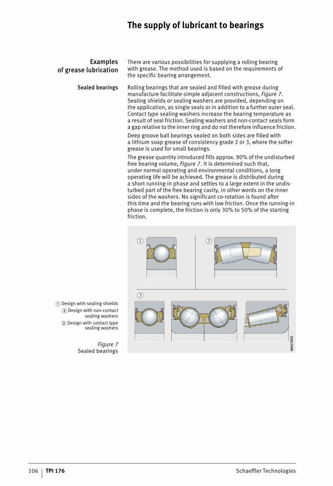
106 TPI 176 Schaeffler Technologies
The supply of lubricant to bearings
Examplesof grease lubrication
There are various possibilities for supplying a rolling bearingwith grease. The method used is based on the requirements ofthe specific bearing arrangement.
Sealed bearings Rolling bearings that are sealed and filled with grease during manufacture facilitate simple adjacent constructions, Figure 7. Sealing shields or sealing washers are provided, depending onthe application, as single seals or in addition to a further outer seal. Contact type sealing washers increase the bearing temperature asa result of seal friction. Sealing washers and non-contact seals form a gap relative to the inner ring and do not therefore influence friction.Deep groove ball bearings sealed on both sides are filled witha lithium soap grease of consistency grade 2 or 3, where the softer grease is used for small bearings.The grease quantity introduced fills approx. 90% of the undisturbed free bearing volume, Figure 7. It is determined such that,under normal operating and environmental conditions, a long operating life will be achieved. The grease is distributed duringa short running-in phase and settles to a large extent in the undis-turbed part of the free bearing cavity, in other words on the inner sides of the washers. No significant co-rotation is found afterthis time and the bearing runs with low friction. Once the running-in phase is complete, the friction is only 30% to 50% of the starting friction.
� Design with sealing shields� Design with non-contact
sealing washers� Design with contact type
sealing washers
Figure 7Sealed bearings 00
0170
CD00
0170
CD
ST4_3561650571_versorgung_der_.fm Seite 106 Donnerstag, 4. April 2013 10:29 10
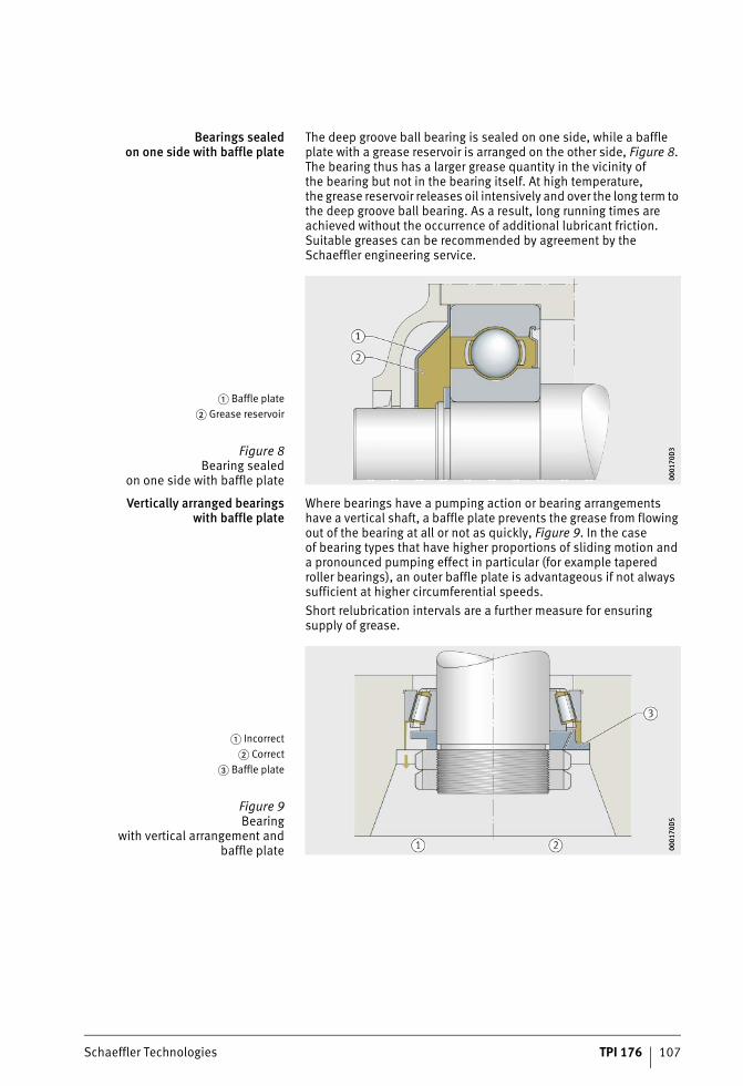
Schaeffler Technologies TPI 176 107
Bearings sealedon one side with baffle plate
The deep groove ball bearing is sealed on one side, while a baffle plate with a grease reservoir is arranged on the other side, Figure 8. The bearing thus has a larger grease quantity in the vicinity ofthe bearing but not in the bearing itself. At high temperature,the grease reservoir releases oil intensively and over the long term to the deep groove ball bearing. As a result, long running times are achieved without the occurrence of additional lubricant friction.Suitable greases can be recommended by agreement by the Schaeffler engineering service.
Vertically arranged bearingswith baffle plate
Where bearings have a pumping action or bearing arrangements have a vertical shaft, a baffle plate prevents the grease from flowing out of the bearing at all or not as quickly, Figure 9. In the caseof bearing types that have higher proportions of sliding motion and a pronounced pumping effect in particular (for example tapered roller bearings), an outer baffle plate is advantageous if not always sufficient at higher circumferential speeds.Short relubrication intervals are a further measure for ensuring supply of grease.
� Baffle plate� Grease reservoir
Figure 8Bearing sealed
on one side with baffle plate 0001
70D
300
0170
D3
� Incorrect� Correct
� Baffle plate
Figure 9Bearing
with vertical arrangement andbaffle plate 00
0170
D5
0001
70D
5
ST4_3561650571_versorgung_der_.fm Seite 107 Donnerstag, 4. April 2013 10:30 10
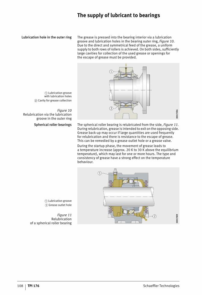
108 TPI 176 Schaeffler Technologies
The supply of lubricant to bearings
Lubrication hole in the outer ring The grease is pressed into the bearing interior via a lubrication groove and lubrication holes in the bearing outer ring, Figure 10.Due to the direct and symmetrical feed of the grease, a uniform supply to both rows of rollers is achieved. On both sides, sufficiently large cavities for collection of the used grease or openings forthe escape of grease must be provided.
Spherical roller bearings The spherical roller bearing is relubricated from the side, Figure 11. During relubrication, grease is intended to exit on the opposing side. Grease back-up may occur if large quantities are used frequentlyfor relubrication and there is resistance to the escape of grease.This can be remedied by a grease outlet hole or a grease valve.During the startup phase, the movement of grease leads toa temperature increase (approx. 20 K to 30 K above the equilibrium temperature), which may last for one or more hours. The type and consistency of grease have a strong effect on the temperature behaviour.
� Lubrication groovewith lubrication holes
� Cavity for grease collection
Figure 10Relubrication via the lubrication
groove in the outer ring 0001
70D
600
0170
D6
� Lubrication groove� Grease outlet hole
Figure 11Relubrication
of a spherical roller bearing 0001
70D
900
0170
D9
ST4_3561650571_versorgung_der_.fm Seite 108 Donnerstag, 4. April 2013 10:30 10
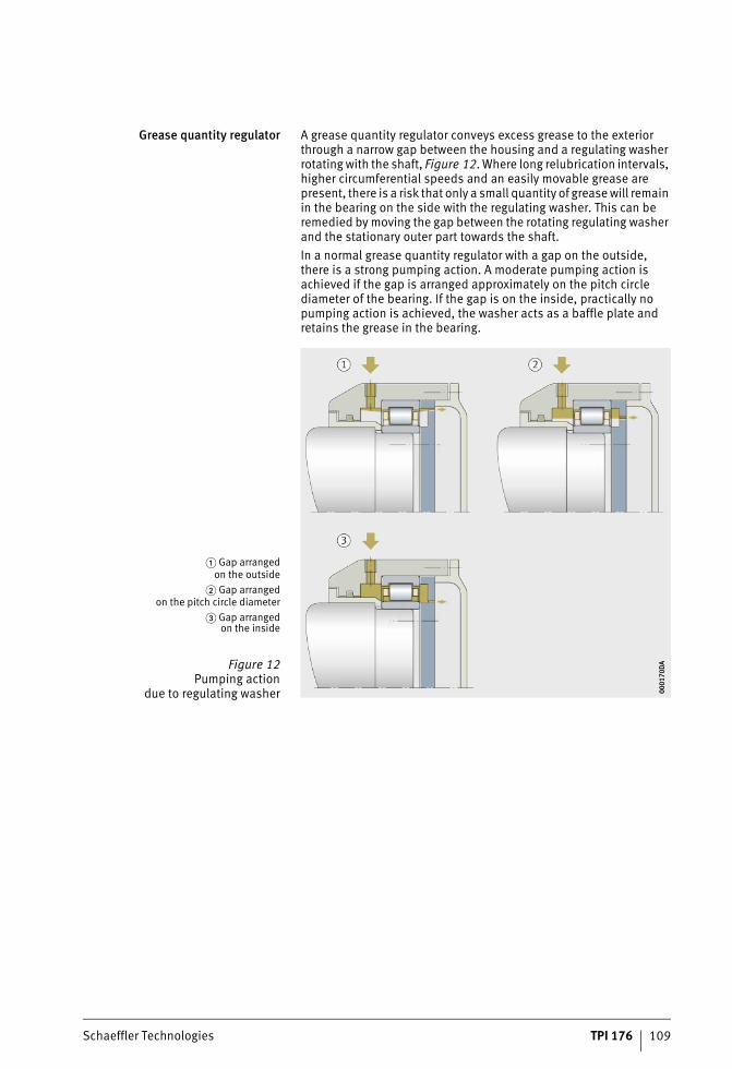
Schaeffler Technologies TPI 176 109
Grease quantity regulator A grease quantity regulator conveys excess grease to the exterior through a narrow gap between the housing and a regulating washer rotating with the shaft, Figure 12. Where long relubrication intervals, higher circumferential speeds and an easily movable grease are present, there is a risk that only a small quantity of grease will remain in the bearing on the side with the regulating washer. This can be remedied by moving the gap between the rotating regulating washer and the stationary outer part towards the shaft.In a normal grease quantity regulator with a gap on the outside,there is a strong pumping action. A moderate pumping action is achieved if the gap is arranged approximately on the pitch circle diameter of the bearing. If the gap is on the inside, practically no pumping action is achieved, the washer acts as a baffle plate and retains the grease in the bearing.
� Gap arrangedon the outside
� Gap arrangedon the pitch circle diameter
� Gap arrangedon the inside
Figure 12Pumping action
due to regulating washer 0001
70D
A00
0170
DA
ST4_3561650571_versorgung_der_.fm Seite 109 Donnerstag, 4. April 2013 10:31 10
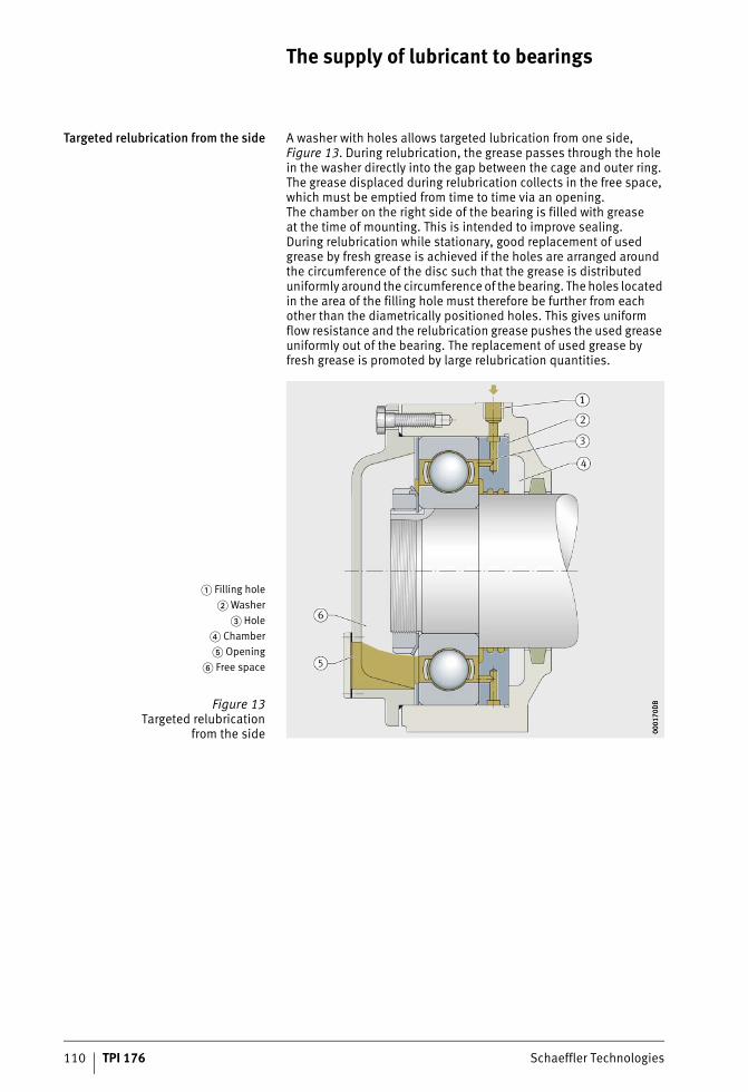
110 TPI 176 Schaeffler Technologies
The supply of lubricant to bearings
Targeted relubrication from the side A washer with holes allows targeted lubrication from one side, Figure 13. During relubrication, the grease passes through the hole in the washer directly into the gap between the cage and outer ring. The grease displaced during relubrication collects in the free space, which must be emptied from time to time via an opening.The chamber on the right side of the bearing is filled with greaseat the time of mounting. This is intended to improve sealing.During relubrication while stationary, good replacement of used grease by fresh grease is achieved if the holes are arranged around the circumference of the disc such that the grease is distributed uniformly around the circumference of the bearing. The holes located in the area of the filling hole must therefore be further from each other than the diametrically positioned holes. This gives uniform flow resistance and the relubrication grease pushes the used grease uniformly out of the bearing. The replacement of used grease by fresh grease is promoted by large relubrication quantities.
� Filling hole� Washer
� Hole� Chamber� Opening
� Free space
Figure 13Targeted relubrication
from the side 0001
70D
B00
0170
DB
ST4_3561650571_versorgung_der_.fm Seite 110 Donnerstag, 4. April 2013 10:32 10
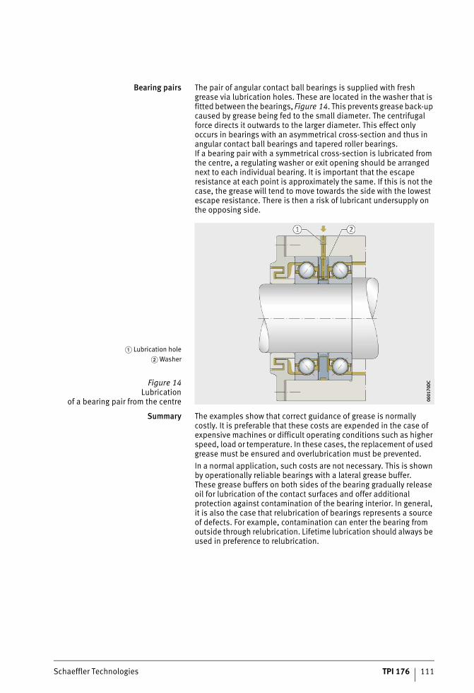
Schaeffler Technologies TPI 176 111
Bearing pairs The pair of angular contact ball bearings is supplied with fresh grease via lubrication holes. These are located in the washer that is fitted between the bearings, Figure 14. This prevents grease back-up caused by grease being fed to the small diameter. The centrifugal force directs it outwards to the larger diameter. This effect only occurs in bearings with an asymmetrical cross-section and thus in angular contact ball bearings and tapered roller bearings.If a bearing pair with a symmetrical cross-section is lubricated from the centre, a regulating washer or exit opening should be arranged next to each individual bearing. It is important that the escape resistance at each point is approximately the same. If this is not the case, the grease will tend to move towards the side with the lowest escape resistance. There is then a risk of lubricant undersupply on the opposing side.
Summary The examples show that correct guidance of grease is normally costly. It is preferable that these costs are expended in the case of expensive machines or difficult operating conditions such as higher speed, load or temperature. In these cases, the replacement of used grease must be ensured and overlubrication must be prevented.In a normal application, such costs are not necessary. This is shown by operationally reliable bearings with a lateral grease buffer.These grease buffers on both sides of the bearing gradually release oil for lubrication of the contact surfaces and offer additional protection against contamination of the bearing interior. In general, it is also the case that relubrication of bearings represents a source of defects. For example, contamination can enter the bearing from outside through relubrication. Lifetime lubrication should always be used in preference to relubrication.
� Lubrication hole� Washer
Figure 14Lubrication
of a bearing pair from the centre 0001
70D
C00
0170
DC
ST4_3561650571_versorgung_der_.fm Seite 111 Donnerstag, 4. April 2013 10:32 10
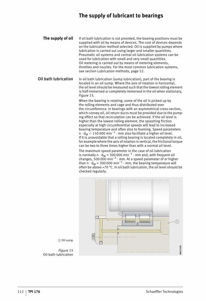
112 TPI 176 Schaeffler Technologies
The supply of lubricant to bearings
The supply of oil If oil bath lubrication is not provided, the bearing positions must be supplied with oil by means of devices. The cost of devices depends on the lubrication method selected. Oil is supplied by pumps where lubrication is carried out using larger and smaller quantities. Pneumatic oil systems and central oil lubrication systems can be used for lubrication with small and very small quantities.Oil metering is carried out by means of metering elements,throttles and nozzles. For the most common lubrication systems,see section Lubrication methods, page 52.
Oil bath lubrication In oil bath lubrication (sump lubrication), part of the bearing is located in an oil sump. Where the axis of rotation is horizontal,the oil level should be measured such that the lowest rolling element is half-immersed or completely immersed in the oil when stationary, Figure 15.When the bearing is rotating, some of the oil is picked up bythe rolling elements and cage and thus distributed overthe circumference. In bearings with an asymmetrical cross-section, which convey oil, oil return ducts must be provided due to the pump-ing effect so that recirculation can be achieved. If the oil level is higher than the lowest rolling element, the splashing friction especially at high circumferential speeds will lead to increased bearing temperature and often also to foaming. Speed parameters n · dM � 150 000 min–1 · mm also facilitate a higher oil level.If it is unavoidable that a rolling bearing is located completely in oil, for example where the axis of rotation is vertical, the frictional torque can be two to three times higher than with a normal oil level.The maximum speed parameter in the case of oil lubricationis normally n · dM = 300 000 min–1 · mm and, with frequent oil changes, 500 000 min–1 · mm. At a speed parameter of or higher than n · dM = 300 000 min–1 · mm, the bearing temperature will often be above +70 °C. In oil bath lubrication, the oil level should be checked regularly.
� Oil sump
Figure 15Oil bath lubrication 00
0172
2D00
0172
2D
ST4_3561650571_versorgung_der_.fm Seite 112 Donnerstag, 4. April 2013 10:32 10
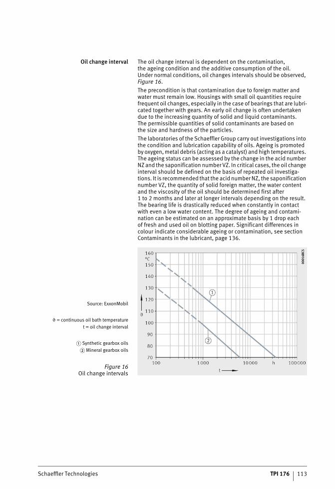
Schaeffler Technologies TPI 176 113
Oil change interval The oil change interval is dependent on the contamination,the ageing condition and the additive consumption of the oil.Under normal conditions, oil changes intervals should be observed, Figure 16.The precondition is that contamination due to foreign matter and water must remain low. Housings with small oil quantities require frequent oil changes, especially in the case of bearings that are lubri-cated together with gears. An early oil change is often undertaken due to the increasing quantity of solid and liquid contaminants.The permissible quantities of solid contaminants are based onthe size and hardness of the particles.The laboratories of the Schaeffler Group carry out investigations into the condition and lubrication capability of oils. Ageing is promoted by oxygen, metal debris (acting as a catalyst) and high temperatures. The ageing status can be assessed by the change in the acid number NZ and the saponification number VZ. In critical cases, the oil change interval should be defined on the basis of repeated oil investiga-tions. It is recommended that the acid number NZ, the saponification number VZ, the quantity of solid foreign matter, the water content and the viscosity of the oil should be determined first after 1 to 2 months and later at longer intervals depending on the result.The bearing life is drastically reduced when constantly in contact with even a low water content. The degree of ageing and contami-nation can be estimated on an approximate basis by 1 drop each of fresh and used oil on blotting paper. Significant differences in colour indicate considerable ageing or contamination, see section Contaminants in the lubricant, page 136.
Source: ExxonMobil
� = continuous oil bath temperaturet = oil change interval
� Synthetic gearbox oils� Mineral gearbox oils
Figure 16Oil change intervals
0001
6BC5
0001
6BC5
ST4_3561650571_versorgung_der_.fm Seite 113 Donnerstag, 4. April 2013 10:33 10
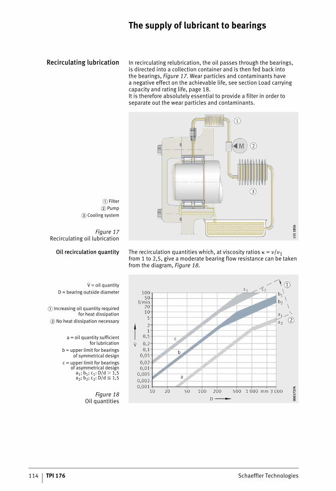
114 TPI 176 Schaeffler Technologies
The supply of lubricant to bearings
Recirculating lubrication In recirculating relubrication, the oil passes through the bearings,is directed into a collection container and is then fed back intothe bearings, Figure 17. Wear particles and contaminants havea negative effect on the achievable life, see section Load carrying capacity and rating life, page 18.It is therefore absolutely essential to provide a filter in order to separate out the wear particles and contaminants.
Oil recirculation quantity The recirculation quantities which, at viscosity ratios � = �/�1from 1 to 2,5, give a moderate bearing flow resistance can be taken from the diagram, Figure 18.
� Filter� Pump
� Cooling system
Figure 17Recirculating oil lubrication 15
5 18
5b15
5 18
5b
V = oil quantityD = bearing outside diameter
� Increasing oil quantity requiredfor heat dissipation
� No heat dissipation necessary
a = oil quantity sufficientfor lubrication
b = upper limit for bearingsof symmetrical design
c = upper limit for bearingsof asymmetrical design
a1; b1; c1: D/d � 1,5a2; b2; c2: D/d � 1,5
Figure 18Oil quantities 00
0173
7A00
0173
7A
ST4_3561650571_versorgung_der_.fm Seite 114 Donnerstag, 4. April 2013 10:33 10
Schaeffler Technologies TPI 176 115
Operating conditions The recirculation quantities are matched to the operating conditions:■ Lubrication of the bearings requires only a very small quantity
of oil. In comparison, the quantities stated as sufficient for lubrication (Figure 18, line a) are large. These oil quantities are recommended in order to ensure that all contact surfaces are still reliably supplied with oil even if the feed of oil to the bearing is unfavourable, in other words if feed is not directly into the bear-ing. The minimum quantities stated are used for lubrication ifa low level of friction is required. The temperature level achieved in this case is comparable with that in oil bath lubrication.
■ If heat dissipation is required, larger oil quantities are necessary (Figure 18, line b). Since each bearing provides some resistance to the flow of oil, there are also upper limits for the oil quantities.
■ For bearings with an asymmetrical cross-section such as angular contact ball bearings, tapered roller bearings or axial spherical roller bearings, larger throughput quantities are permissible (Figure 18, line c) than for bearings with a symmetrical cross-section. This is due to the fact that bearings with an asymmetrical cross-section provide less resistance to the oil flow due to their pumping action.
The stated limits are based on the precondition of unpressurised feed and back-up of oil on the feed side of the bearing as far as just below the shaft. The oil quantity that must be provided in individual cases in order to maintain an adequately low bearing temperature is dependent on the conditions of heat input and dissipation.Values higher than those in region c according to Figure 18 are not advisable. The correct oil quantity can be determined by temperature measurement during commissioning of the machine and then regulated accordingly.
Injection lubrication With increasing circumferential speed, bearings with a symmetrical cross-section provide increasing resistance to the oil flow. If larger recirculation quantities are planned, the oil is injected specifically into the gap between the cage and bearing ring in the case of rolling bearings rotating at high speeds. With oil injection, smaller splash-ing losses occur.Normal oil quantities can be determined as a function of the speed parameter and bearing size, Figure 19, page 116. Furthermore, the nozzle diameter can be determined, Figure 20, page 116.The back-up of oil ahead of the bearing is prevented by injecting oil at points that allow free entry into the bearing. If the outlet ducts ahead of and after the bearing arrangement are adequately dimensioned, this will ensure that the oil not consumed bythe bearing and flowing through the bearing can escape freely.
ST4_3561650571_versorgung_der_.fm Seite 115 Donnerstag, 4. April 2013 10:34 10
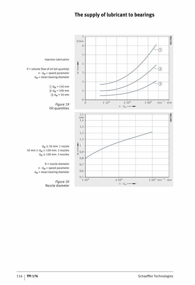
116 TPI 176 Schaeffler Technologies
The supply of lubricant to bearings
Injection lubrication
V = volume flow of oil (oil quantity)n · dM = speed parameter
dM = mean bearing diameter
� dM = 150 mm� dM = 100 mm
� dM = 50 mm
Figure 19Oil quantities
0001
70D
D00
0170
DD
dM � 50 mm: 1 nozzle50 mm � dM � 100 mm: 2 nozzles
dM � 100 mm: 3 nozzles
D = nozzle diametern · dM = speed parameter
dM = mean bearing diameter
Figure 20Nozzle diameter
0001
70D
E00
0170
DE
ST4_3561650571_versorgung_der_.fm Seite 116 Donnerstag, 4. April 2013 10:34 10
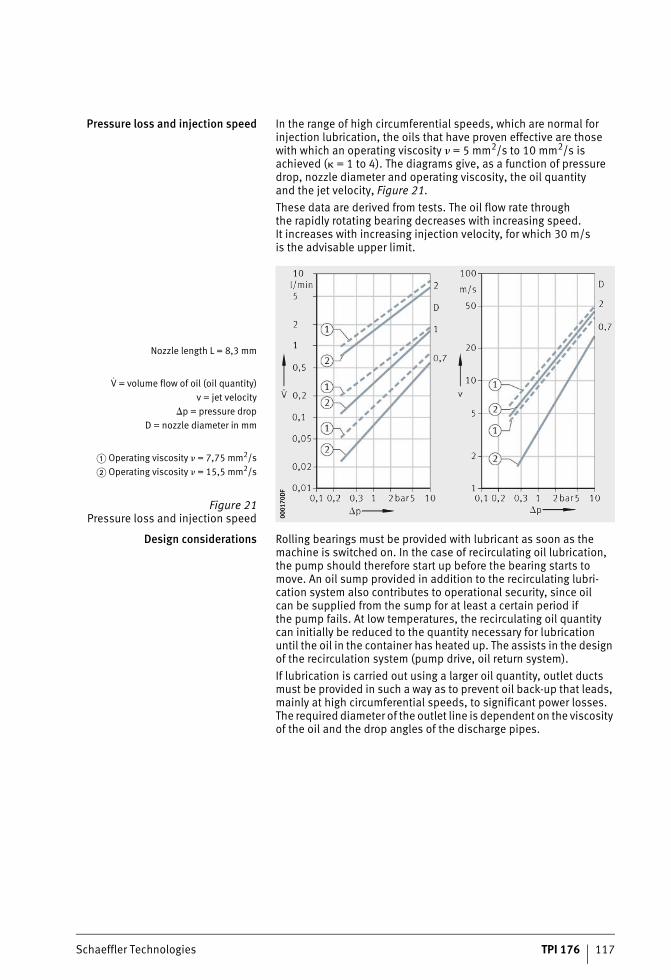
Schaeffler Technologies TPI 176 117
Pressure loss and injection speed In the range of high circumferential speeds, which are normal for injection lubrication, the oils that have proven effective are those with which an operating viscosity � = 5 mm2/s to 10 mm2/s is achieved (� = 1 to 4). The diagrams give, as a function of pressure drop, nozzle diameter and operating viscosity, the oil quantityand the jet velocity, Figure 21.These data are derived from tests. The oil flow rate throughthe rapidly rotating bearing decreases with increasing speed.It increases with increasing injection velocity, for which 30 m/sis the advisable upper limit.
Design considerations Rolling bearings must be provided with lubricant as soon as the machine is switched on. In the case of recirculating oil lubrication, the pump should therefore start up before the bearing starts to move. An oil sump provided in addition to the recirculating lubri-cation system also contributes to operational security, since oil can be supplied from the sump for at least a certain period if the pump fails. At low temperatures, the recirculating oil quantity can initially be reduced to the quantity necessary for lubrication until the oil in the container has heated up. The assists in the design of the recirculation system (pump drive, oil return system).If lubrication is carried out using a larger oil quantity, outlet ducts must be provided in such a way as to prevent oil back-up that leads, mainly at high circumferential speeds, to significant power losses. The required diameter of the outlet line is dependent on the viscosity of the oil and the drop angles of the discharge pipes.
Nozzle length L = 8,3 mm
V = volume flow of oil (oil quantity)v = jet velocity
�p = pressure dropD = nozzle diameter in mm
� Operating viscosity � = 7,75 mm2/s� Operating viscosity � = 15,5 mm2/s
Figure 21Pressure loss and injection speed 00
0170
DF
0001
70D
F
ST4_3561650571_versorgung_der_.fm Seite 117 Donnerstag, 4. April 2013 10:35 10
118 TPI 176 Schaeffler Technologies
The supply of lubricant to bearings
Diameter of outlet line For oils with an operating viscosity of up to 500 mm2/s,the diameter of the outlet line can be stated approximately in mm:
da mmFree diameter of outlet linem l/minOil throughput quantity.
For more precise dimensioning in the drop region of the outlet line from 1% to 5%, the diameter is as follows:
da mmFree diameter of outlet linem l/minOil throughput quantity� mm2/sOperating viscosityG %Drop.
Fill quantity of oil container
M lFill quantity of oil containerm l/minOil throughput quantityz –Circulation parameter.
The fill quantity of the oil container is based on the oil throughput.In general, the fill quantity is selected such that circulation occurs approx. z = 3 to 8 times per hour.At a low circulation parameter, contaminants are easily deposited in the oil container, the oil can be cooled and does not age so quickly. At a high circulation parameter, there is a risk of excessive foaming, see section Foaming behaviour, page 147.
ST4_3561650571_versorgung_der_.fm Seite 118 Donnerstag, 4. April 2013 10:36 10
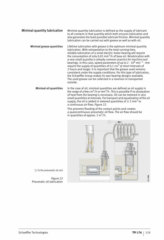
Schaeffler Technologies TPI 176 119
Minimal quantity lubrication Minimal quantity lubrication is defined as the supply of lubricantto all contacts in that quantity which both ensures lubrication and also generates the least possible lubricant friction. Minimal quantity lubrication can be carried out with grease as well as with oil.
Minimal grease quantities Lifetime lubrication with grease is the optimum minimal quantity lubrication. With extrapolation to the total running time,reliable lubrication of a small electric motor bearing will requirethe consumption of only 0,05 mm3/h of base oil. Relubrication with a very small quantity is already common practice for machine tool bearings. In this case, speed parameters of up to 2 · 106 min–1 · mm require the supply of quantities of 0,1 cm3 at short intervals of 2 hours and longer. It is important that the grease used remains consistent under the supply conditions. For this type of lubrication, the Schaeffler Group makes its own bearing designs available.The used grease can be collected in a reservoir or transported outside.
Minimal oil quantities In the case of oil, minimal quantities are defined as oil supply inthe range of a few cm3/h or mm3/h. This is possible if no dissipation of heat from the bearing is necessary. Oil can be metered in very small quantities at intervals. For transport and equalisation of the oil supply, the oil is added in metered quantities of � 5 mm3 toa continuous air flow, Figure 22.This prevents flooding of the contact points and createsa quasicontinuous pneumatic oil flow. The air flow should bein quantities of approx. 2 m3/h.
� To the pneumatic oil unit
Figure 22Pneumatic oil lubrication 15
5 18
9b15
5 18
9b
ST4_3561650571_versorgung_der_.fm Seite 119 Donnerstag, 4. April 2013 10:36 10
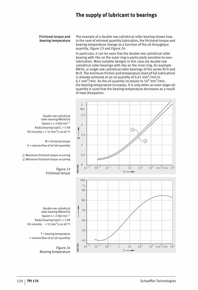
120 TPI 176 Schaeffler Technologies
The supply of lubricant to bearings
Frictional torque andbearing temperature
The example of a double row cylindrical roller bearing shows how,in the case of minimal quantity lubrication, the frictional torque and bearing temperature change as a function of the oil throughput quantity, Figure 23 and Figure 24.In particular, it can be seen that the double row cylindrical roller bearing with ribs on the outer ring is particularly sensitive to over-lubrication. More suitable designs in this case are double row cylindrical roller bearings with ribs on the inner ring, for example NN30, or single row cylindrical roller bearings of the series N10 and N19. The minimum friction and temperature (start of full lubrication) is already achieved at an oil quantity of 0,01 mm3/min to 0,1 mm3/min. As the oil quantity increases to 104 mm3/min,the bearing temperature increases. It is only when an even larger oil quantity is used that the bearing temperature decreases as a result of heat dissipation.
Double row cylindricalroller bearing NNU4926Speed n = 2 000 min–1
Radial bearing load Fr = 5 kNOil viscosity � = 32 mm2/s at 40 °C
M = frictional torqueV = volume flow of oil (oil quantity)
� Maximum frictional torque occurring� Minimum frictional torque occurring
Figure 23Frictional torque 00
0170
E000
0170
E0
Double row cylindricalroller bearing NNU4926Speed n = 2 000 min–1
Radial bearing load Fr = 5 kNOil viscosity = 32 mm2/s at 40 °C
T = bearing temperature= volume flow of oil (oil quantity)
Figure 24 Bearing temperature 00
0170
E100
0170
E1
ST4_3561650571_versorgung_der_.fm Seite 120 Donnerstag, 4. April 2013 10:36 10
Schaeffler Technologies TPI 176 121
Bearing type The oil quantity required for adequate supply is heavily dependent on the bearing type. Bearings with a pumping action in the flow direction thus require a relatively large oil quantity. In contrast,the oil requirement of double row bearings without pumping action is extremely small if the oil is fed between the rows of rollers. The oil is prevented from flowing out by the rotating rolling elements.The precondition for lubrication with very small quantities is thatthe small oil quantity gives sufficient coating of all contact surfaces in the bearing and, in particular, the sliding contact surfaces such as rib and cage guidance surfaces, which are particular challengingin terms of lubrication technology. In machine tool bearing arrange-ments with ball bearings and cylindrical roller bearings, oil supply directly into the bearing and, in the case of angular contact ball bearings in the pumping direction, has proved effective.The oil quantities in minimal quantity lubrication are statedfor various bearing types as a function of bearing size, contact angle (pumping behaviour) and the speed parameter, Figure 25, page 122.In bearings with pumping action, the oil quantity should be increased as a function of the speed, since the minimum oil require-ment and the pumping action increases with increasing speed.In bearings with contact between ribs and the end faces of rollers, such as tapered roller bearings, an additional oil feed directly tothe roller end faces – opposing the pumping direction – has proved favourable. The precondition for extremely low oil quantities area reliable feed between the cage and inner ring as well as high dimensional accuracy of the adjacent parts. The viscosity of the oil should, in the case of an extremely small oil quantity, conform toa viscosity ratio � = �/�1 = 8 to 10 and contain suitable agents.In contrast, the uniform feed of a large oil quantity or the pulse-type feed even of small quantities leads, in the case of radial cylindrical roller bearings, and especially at high circumferential speeds,to a spontaneous increase in lubricant friction and non-uniform heating of the bearing rings. In bearings with a small radial internal clearance, for example in machine tool bearing arrangements,this can lead to failure of the bearings as a result of radial tensioning.
ST4_3561650571_versorgung_der_.fm Seite 121 Donnerstag, 4. April 2013 10:37 10
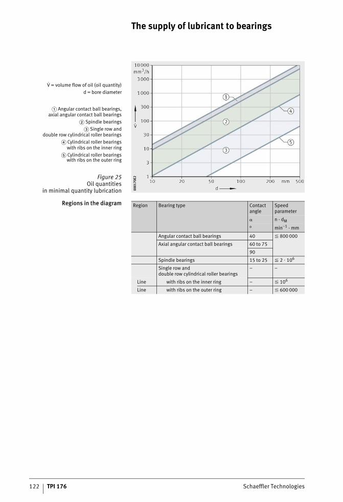
122 TPI 176 Schaeffler Technologies
The supply of lubricant to bearings
Regions in the diagram
V = volume flow of oil (oil quantity)d = bore diameter
� Angular contact ball bearings,axial angular contact ball bearings
� Spindle bearings� Single row and
double row cylindrical roller bearings� Cylindrical roller bearings
with ribs on the inner ring� Cylindrical roller bearings
with ribs on the outer ring
Figure 25Oil quantities
in minimal quantity lubrication 0001
70E2
0001
70E2
Region Bearing type Contactangle
Speed parameter
� n · dM
° min–1 · mm
Angular contact ball bearings 40 � 800 000
Axial angular contact ball bearings 60 to 75
90
Spindle bearings 15 to 25 � 2 � 106
Single row anddouble row cylindrical roller bearings
– –
Line with ribs on the inner ring – � 106
Line with ribs on the outer ring – � 600 000
ST4_3561650571_versorgung_der_.fm Seite 122 Donnerstag, 4. April 2013 10:37 10
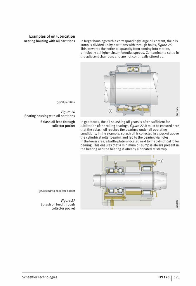
Schaeffler Technologies TPI 176 123
Examples of oil lubricationBearing housing with oil partitions In larger housings with a correspondingly large oil content, the oils
sump is divided up by partitions with through holes, Figure 26.This prevents the entire oil quantity from coming into motion, principally at higher circumferential speeds. Contaminants settle in the adjacent chambers and are not continually stirred up.
Splash oil feed throughcollector pocket
In gearboxes, the oil splashing off gears is often sufficient for lubrication of the rolling bearings, Figure 27. It must be ensured here that the splash oil reaches the bearings under all operating conditions. In the example, splash oil is collected in a pocket above the cylindrical roller bearing and fed to the bearing via holes.In the lower area, a baffle plate is located next to the cylindrical roller bearing. This ensures that a minimum oil sump is always present in the bearing and the bearing is already lubricated at startup.
� Oil partition
Figure 26Bearing housing with oil partitions 00
0170
E300
0170
E3
� Oil feed via collector pocket
Figure 27Splash oil feed through
collector pocket 0001
70F1
0001
70F1
ST4_3561650571_versorgung_der_.fm Seite 123 Donnerstag, 4. April 2013 10:37 10

124 TPI 176 Schaeffler Technologies
The supply of lubricant to bearings
Bearings with pumping action As in the case of all bearings with an asymmetrical cross-section, tapered roller bearings have a pumping action, Figure 28.This pumping action, which is heavily dependent on the circum-ferential speed, can be utilised in recirculating oil lubrication. The outlet holes should be designed such that no oil back-up occurs adjacent to the bearing.
Oil injection lubrication In oil injection lubrication, the oil is injected between the cage and inner ring, Figure 29. Oil back-up ahead of and after the bearings is prevented by oil outlet ducts. If the bearings have a pumping action, injection is carried out on the side with the smaller raceway diameter. In the case of tapered roller bearings rotating at very high speeds, injection is additionally carried out to the roller end faces on the other side. This counteracts undersupply of lubricant between the rib and end faces of the rollers.
� Oil feed via collector pocket� Outlet hole
Figure 28Increasing oil recirculation 00
0170
FD00
0170
FD
Angular contact ball bearingTapered roller bearing
� Outlet holes
Figure 29Oil injection lubrication 00
0171
0D00
0171
0D
ST4_3561650571_versorgung_der_.fm Seite 124 Donnerstag, 4. April 2013 10:38 10
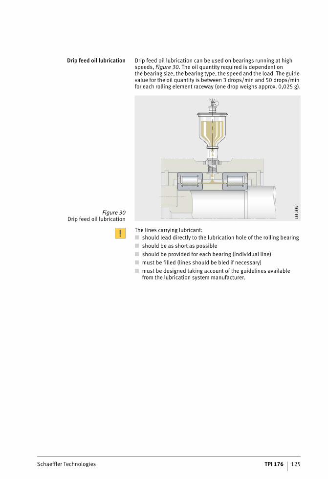
Schaeffler Technologies TPI 176 125
Drip feed oil lubrication Drip feed oil lubrication can be used on bearings running at high speeds, Figure 30. The oil quantity required is dependent onthe bearing size, the bearing type, the speed and the load. The guide value for the oil quantity is between 3 drops/min and 50 drops/min for each rolling element raceway (one drop weighs approx. 0,025 g).
The lines carrying lubricant:■ should lead directly to the lubrication hole of the rolling bearing■ should be as short as possible■ should be provided for each bearing (individual line)■ must be filled (lines should be bled if necessary)■ must be designed taking account of the guidelines available
from the lubrication system manufacturer.
Figure 30Drip feed oil lubrication 15
5 18
8b15
5 18
8b
ST4_3561650571_versorgung_der_.fm Seite 125 Donnerstag, 4. April 2013 10:39 10
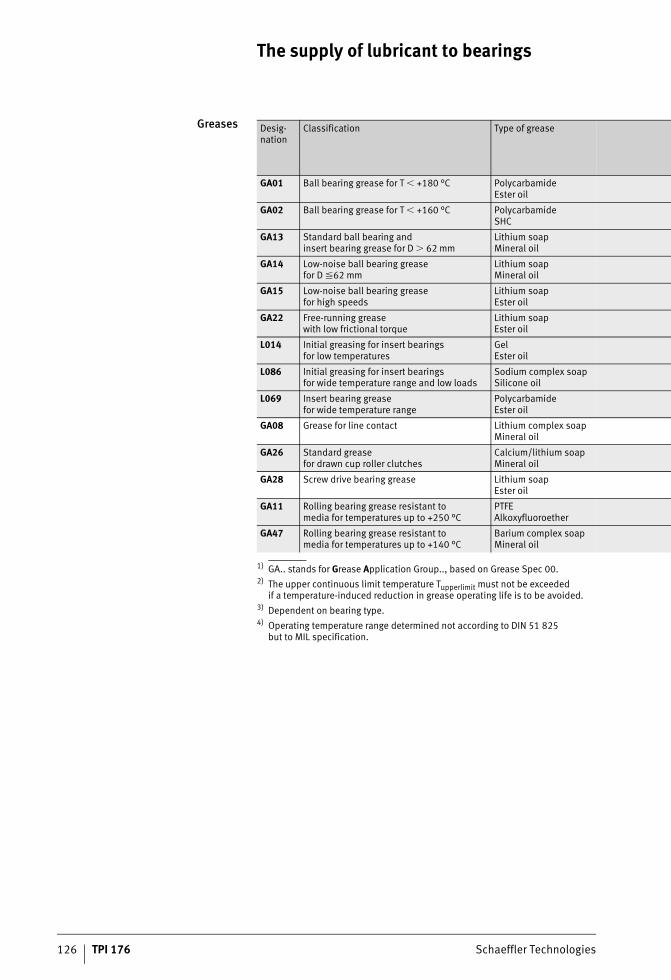
The supply of lubricant to bearings
126 TPI 176 Schaeffler Technologies
Greases
1) GA.. stands for Grease Application Group.., based on Grease Spec 00.2) The upper continuous limit temperature Tupperlimit must not be exceeded
if a temperature-induced reduction in grease operating life is to be avoided.3) Dependent on bearing type.4) Operating temperature range determined not according to DIN 51 825
but to MIL specification.
Desig-nation
Classification Type of grease
GA01 Ball bearing grease for T � +180 °C PolycarbamideEster oil
GA02 Ball bearing grease for T � +160 °C PolycarbamideSHC
GA13 Standard ball bearing andinsert bearing grease for D � 62 mm
Lithium soapMineral oil
GA14 Low-noise ball bearing greasefor D �62 mm
Lithium soapMineral oil
GA15 Low-noise ball bearing greasefor high speeds
Lithium soapEster oil
GA22 Free-running greasewith low frictional torque
Lithium soapEster oil
L014 Initial greasing for insert bearingsfor low temperatures
GelEster oil
L086 Initial greasing for insert bearingsfor wide temperature range and low loads
Sodium complex soapSilicone oil
L069 Insert bearing greasefor wide temperature range
PolycarbamideEster oil
GA08 Grease for line contact Lithium complex soapMineral oil
GA26 Standard greasefor drawn cup roller clutches
Calcium/lithium soapMineral oil
GA28 Screw drive bearing grease Lithium soapEster oil
GA11 Rolling bearing grease resistant tomedia for temperatures up to +250 °C
PTFEAlkoxyfluoroether
GA47 Rolling bearing grease resistant tomedia for temperatures up to +140 °C
Barium complex soapMineral oil
ST4_3561650571_versorgung_der_.fm Seite 126 Donnerstag, 4. April 2013 10:39 10
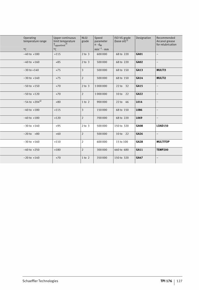
Schaeffler Technologies TPI 176 127
Operating temperature range
Upper continuous limit temperatureTupperlimit
2)
NLGI grade
Speed parametern · dM
ISO VG grade(base oil)3)
Designation Recommended Arcanol greasefor relubrication
°C °C min–1 · mm
–40 to +180 +115 2 to 3 600 000 68 to 220 GA01 –
–40 to +160 +85 2 to 3 500 000 68 to 220 GA02 –
–30 to +140 +75 3 500 000 68 to 150 GA13 MULTI3
–30 to +140 +75 2 500 000 68 to 150 GA14 MULTI2
–50 to +150 +70 2 to 3 1 000 000 22 to 32 GA15 –
–50 to +120 +70 2 1 000 000 10 to 22 GA22 –
–54 to +2044) +80 1 to 2 900 000 22 to 46 L014 –
–40 to +180 +115 3 150 000 68 to 150 L086 –
–40 to +180 +120 2 700 000 68 to 220 L069 –
–30 to +140 +95 2 to 3 500 000 150 to 320 GA08 LOAD150
–20 to +80 +60 2 500 000 10 to 22 GA26 –
–30 to +160 +110 2 600 000 15 to 100 GA28 MULTITOP
–40 to +250 +180 2 300 000 460 to 680 GA11 TEMP200
–20 to +140 +70 1 to 2 350 000 150 to 320 GA47 –
ST4_3561650571_versorgung_der_.fm Seite 127 Donnerstag, 4. April 2013 10:39 10
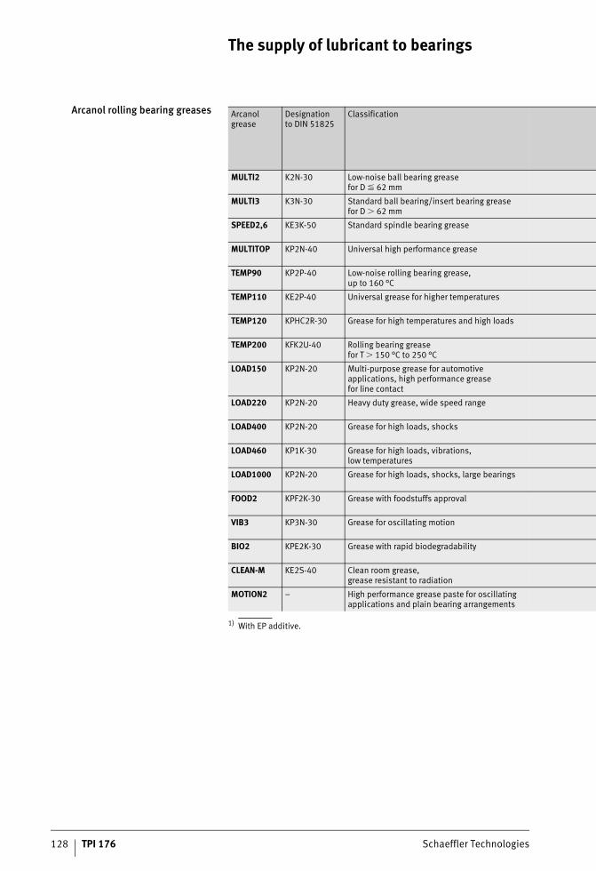
The supply of lubricant to bearings
128 TPI 176 Schaeffler Technologies
Arcanol rolling bearing greases
1) With EP additive.
Arcanol grease
Designationto DIN 51825
Classification
MULTI2 K2N-30 Low-noise ball bearing greasefor D � 62 mm
MULTI3 K3N-30 Standard ball bearing/insert bearing greasefor D � 62 mm
SPEED2,6 KE3K-50 Standard spindle bearing grease
MULTITOP KP2N-40 Universal high performance grease
TEMP90 KP2P-40 Low-noise rolling bearing grease,up to 160 °C
TEMP110 KE2P-40 Universal grease for higher temperatures
TEMP120 KPHC2R-30 Grease for high temperatures and high loads
TEMP200 KFK2U-40 Rolling bearing greasefor T � 150 °C to 250 °C
LOAD150 KP2N-20 Multi-purpose grease for automotive applications, high performance greasefor line contact
LOAD220 KP2N-20 Heavy duty grease, wide speed range
LOAD400 KP2N-20 Grease for high loads, shocks
LOAD460 KP1K-30 Grease for high loads, vibrations,low temperatures
LOAD1000 KP2N-20 Grease for high loads, shocks, large bearings
FOOD2 KPF2K-30 Grease with foodstuffs approval
VIB3 KP3N-30 Grease for oscillating motion
BIO2 KPE2K-30 Grease with rapid biodegradability
CLEAN-M KE2S-40 Clean room grease,grease resistant to radiation
MOTION2 – High performance grease paste for oscillating applications and plain bearing arrangements
ST4_3561650571_versorgung_der_.fm Seite 128 Donnerstag, 4. April 2013 10:39 10
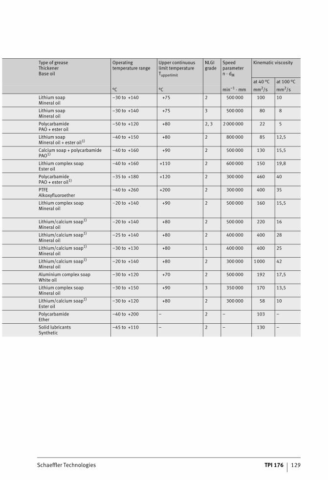
Schaeffler Technologies TPI 176 129
Type of greaseThickenerBase oil
Operatingtemperature range
Upper continuous limit temperatureTupperlimit
NLGI grade
Speed parametern · dM
Kinematic viscosity
at 40 °C at 100 °C
°C °C min–1 · mm mm2/s mm2/s
Lithium soapMineral oil
–30 to +140 +75 2 500 000 100 10
Lithium soapMineral oil
–30 to +140 +75 3 500 000 80 8
PolycarbamidePAO + ester oil
–50 to +120 +80 2, 3 2 000 000 22 5
Lithium soapMineral oil + ester oil1)
–40 to +150 +80 2 800 000 85 12,5
Calcium soap + polycarbamidePAO1)
–40 to +160 +90 2 500 000 130 15,5
Lithium complex soapEster oil
–40 to +160 +110 2 600 000 150 19,8
PolycarbamidePAO + ester oil1)
–35 to +180 +120 2 300 000 460 40
PTFEAlkoxyfluoroether
–40 to +260 +200 2 300 000 400 35
Lithium complex soapMineral oil
–20 to +140 +90 2 500 000 160 15,5
Lithium/calcium soap1)
Mineral oil–20 to +140 +80 2 500 000 220 16
Lithium/calcium soap1)
Mineral oil–25 to +140 +80 2 400 000 400 28
Lithium/calcium soap1)
Mineral oil–30 to +130 +80 1 400 000 400 25
Lithium/calcium soap1)
Mineral oil–20 to +140 +80 2 300 000 1000 42
Aluminium complex soapWhite oil
–30 to +120 +70 2 500 000 192 17,5
Lithium complex soapMineral oil
–30 to +150 +90 3 350 000 170 13,5
Lithium/calcium soap1)
Ester oil–30 to +120 +80 2 300 000 58 10
PolycarbamideEther
–40 to +200 – 2 – 103 –
Solid lubricantsSynthetic
–45 to +110 – 2 – 130 –
ST4_3561650571_versorgung_der_.fm Seite 129 Donnerstag, 4. April 2013 10:39 10

130 TPI 176 Schaeffler Technologies
Miscibility of lubricants
Miscibility of greases and oils Care must be taken when mixing different lubricants On the one hand, oils or the base oils of greases and their thickeners may not be compatible, see tables. On the other hand, the effect of additives and the performance capability of lubricant mixtures cannot be esti-mated without appropriate testing.Mixing of greases should be avoided. If this is not possible, it is recommended that the substances to be mixed have:■ the same base oil type■ a compatible thickener type■ similar base oil viscosities (the difference must be no more than
one ISO VG grade)■ the same consistency (NLGI grade).
Miscibility of base oils
Compatibilityof different thickener types
Mineral oil
PAO Ester oil Polygly-col oil
Silicone oil
Alkoxy-fluoro oil
Mineral oil + + + – o –
PAO + + + – o –
Ester oil + + + o – –
Polyglycol oil – – o + – –
Silicone oil o o – – + –
Alkoxyfluoro oil – – – – – +
Lithium soap
Lithium complex
Sodium complex
Calcium complex
Aluminium complex
Lithium soap + + – + –
Lithium complex
+ + o + o
Sodium complex
– o + o o
Calcium complex
+ + o + o
Aluminium complex
– o o o +
Barium complex
+ o o o o
Bentonite – – – 0 –
Polycarbamide – o o o –
PTFE + + + + +
Definition of the symbols:+ Mixing generally non-criticalo Miscible in individual cases, but checking should be carried out– Mixing not permissible
ST4_3561657867_mischbarkeit_vo.fm Seite 130 Donnerstag, 4. April 2013 10:39 10
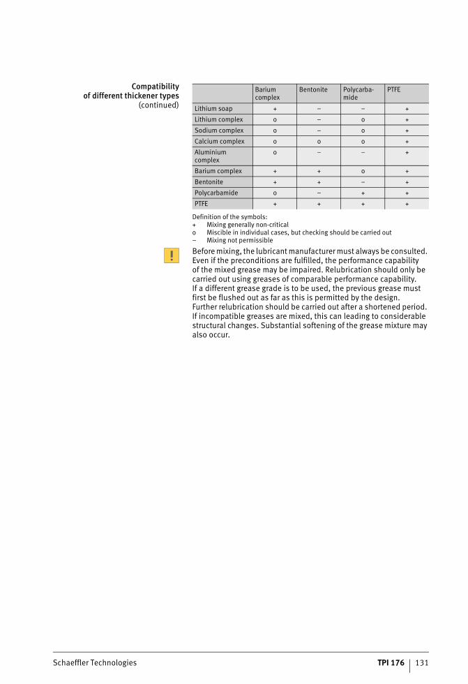
Schaeffler Technologies TPI 176 131
Compatibilityof different thickener types
(continued)
Before mixing, the lubricant manufacturer must always be consulted. Even if the preconditions are fulfilled, the performance capability of the mixed grease may be impaired. Relubrication should only be carried out using greases of comparable performance capability. If a different grease grade is to be used, the previous grease must first be flushed out as far as this is permitted by the design. Further relubrication should be carried out after a shortened period. If incompatible greases are mixed, this can leading to considerable structural changes. Substantial softening of the grease mixture may also occur.
Barium complex
Bentonite Polycarba-mide
PTFE
Lithium soap + – – +
Lithium complex o – o +
Sodium complex o – o +
Calcium complex o o o +
Aluminium complex
o – – +
Barium complex + + o +
Bentonite + + – +
Polycarbamide o – + +
PTFE + + + +
Definition of the symbols:+ Mixing generally non-criticalo Miscible in individual cases, but checking should be carried out– Mixing not permissible
ST4_3561657867_mischbarkeit_vo.fm Seite 131 Donnerstag, 4. April 2013 10:39 10
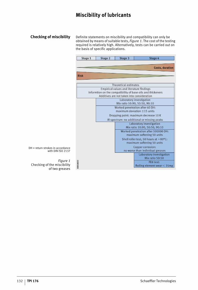
132 TPI 176 Schaeffler Technologies
Miscibility of lubricants
Checking of miscibility Definite statements on miscibility and compatibility can only be obtained by means of suitable tests, Figure 1. The cost of the testing required is relatively high. Alternatively, tests can be carried out on the basis of specific applications.
DH = return strokes in accordancewith DIN ISO 2137
Figure 1Checking of the miscibility
of two greases 0001
A033
0001
A033
ST4_3561657867_mischbarkeit_vo.fm Seite 132 Donnerstag, 4. April 2013 10:39 10
Schaeffler Technologies TPI 176 133
Lubrication systems and monitoring
Lever grease gun In difficult operating conditions or aggressive environments, rolling bearings must be frequently relubricated via lubrication nipples. This can be carried out easily, cleanly and quickly using lever grease guns.The devices available from Schaeffler conform to DIN 1283 and the gun can filled either with loose grease or using a cartridge in accordance with DIN 1284.
Motion Guard When automatic lubricators are used for controlled relubrication, a sufficient quantity of fresh grease is continuously supplied to the contact points of the rolling bearing. This extends the lubrication and maintenance intervals and shortens the downtime of the plant.There are three series of lubricator:■ Motion Guard COMPACT
– Single-point lubrication system comprising an activation screw and housing, filled with 120 cm3 grease
■ Motion Guard CHAMPION– Single-point lubrication system comprising an LC unit
(Lubricant Cartridge) with a volume of 120 cm3 or 250 cm3 and a battery set
■ Motion Guard CONCEPT 6– Single-point lubrication system with distributor,
expandable to multi-point lubrication system, cartridge with volume of 250 cm3 or 500 cm3.
ST4_3766756107_schmiersysteme_.fm Seite 133 Donnerstag, 4. April 2013 10:40 10
134 TPI 176 Schaeffler Technologies
Lubrication systems and monitoring
Condition monitoring Condition monitoring on the basis of vibrations is currently the most reliable method for detecting damage at an early stage. A distinction is made here between offline and online monitoring. In offline monitoring, machinery is examined by vibration analysis at regular intervals, for example every four weeks. In online monitoring, the machine condition is subject to continuous monitoring. Both methods work on the basis of signals and facilitate assessment of the condition of equipment and components. Imbalance and misalignment defects can be detected accurately, as well as rolling bearing damage and gear tooth defects. Depending on the priority and location of the machinery, the operator must decide which method of condition monitoring is most suitable for his requirements.In the field of condition monitoring, Schaeffler Technologies AG & Co. KG offers a comprehensive product portfolio, ranging from simple vibration monitors to complex monitoring systems for a large number of measurement points. Vibration measuring devices help to detect incipient damage to rotating components at an early stage. As a result, unplanned downtime can be prevented and maintenance costs can be reduced. As necessary, the Business Division Industrial Aftermarket (IAM) of Schaeffler can advise on the selection of suitable monitoring methods. Further product information is givenin Catalogue IS 1.
ST4_3766756107_schmiersysteme_.fm Seite 134 Donnerstag, 4. April 2013 10:40 10

Schaeffler Technologies TPI 176 135
ST4_3766756107_schmiersysteme_.fm Seite 135 Donnerstag, 4. April 2013 10:40 10
Contaminants in the lubricant
#tpi176__en_gb__de.xml_FM8_en_gb.book Seite 136 Donnerstag, 4. April 2013 8:22 08
Schaeffler Technologies TPI 176 137
Page
Contaminants in the lubricant
Contaminants in the lubricant Solid foreign matter ................................................................ 138Reduction in the concentration of foreign matter ................. 139Filtration values ................................................................. 141
Liquid contaminants ............................................................... 143The influence of water in oils .............................................. 143The influence of water in greases........................................ 145
Gaseous contaminants ........................................................... 146Dissolved air in oil.............................................................. 146Finely distributed air in oil .................................................. 146Air release.......................................................................... 146Foaming behaviour............................................................. 147
Cleaning of contaminated bearings ......................................... 148
ST4_3750424203_ivz.fm Seite 137 Donnerstag, 4. April 2013 10:41 10
138 TPI 176 Schaeffler Technologies
Contaminants in the lubricant
In practice, there are hardly any lubrication systems that are completely free of contaminants. Contaminants that are commonto applications are already taken into consideration in determining the fatigue life and operating life, since the calculation methods are based on results from practice and tests. If a level of contamination higher than in the normal application is unavoidable, this will lead to reduced running times or premature failures. If the level of cleanliness is particularly good, however, longer running times can be achieved.Due to the production processes, all lubricants already containa certain proportion of contaminants. The minimum requirementsfor lubricants defined in DIN standards include limit values for permissible contamination in production. In the delivered condition, lubricants contain additional contaminants from the containers.At initial mounting, contaminants often also enter the bearing due to inadequate cleaning of machine parts and oil lines.During operation, the bearing may become contaminated due to inadequate sealing as a result of open points in the lubrication system (oil container, pump). Contaminants may also enter the bearing during maintenance, for example due to contamination on the lubrication nipple or on the nozzle of the grease gun as well as during greasing by hand.When determining the harmful influence of contaminants,the following are particularly important for all lubricants:■ the type and hardness of foreign matter■ the concentration of foreign matter in the lubricant■ the particle size of the foreign matter.
Solid foreign matter Solid foreign matter leads to wear and premature fatigue. The higher the hardness of the overrolled particles (for example iron swarf, grinding swarf, moulding sand, corundum) and the smaller the bearings, the greater the reduction in the life. A correlation between the indentation diameter and the relative life can be derived onthe basis of artificially created indentations, Figure 1, page 139.For information on taking account of hard contaminants as an influ-ence on reduced life, see section Load carrying capacity and rating life, page 18.
ST4_3750608907_verunreinigunge.fm Seite 138 Donnerstag, 4. April 2013 10:41 10
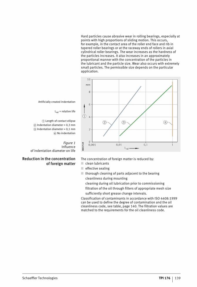
Schaeffler Technologies TPI 176 139
Hard particles cause abrasive wear in rolling bearings, especially at points with high proportions of sliding motion. This occurs,for example, in the contact area of the roller end face and rib in tapered roller bearings or at the raceway ends of rollers in axial cylindrical roller bearings. The wear increases as the hardness ofthe particles increases. It also increases in an approximately proportional manner with the concentration of the particles inthe lubricant and the particle size. Wear also occurs with extremely small particles. The permissible size depends on the particular application.
Reduction in the concentrationof foreign matter
The concentration of foreign matter is reduced by:■ clean lubricants■ effective sealing■ thorough cleaning of parts adjacent to the bearing
cleanliness during mountingcleaning during oil lubrication prior to commissioningfiltration of the oil through filters of appropriate mesh sizesufficiently short grease change intervals.
Classification of contaminants in accordance with ISO 4408:1999 can be used to define the degree of contamination and the oil cleanliness code, see table, page 140. The filtration values are matched to the requirements for the oil cleanliness code.
Artificially created indentation
Lrel = relative life
� Length of contact ellipse� Indentation diameter = 0,3 mm� Indentation diameter = 0,1 mm
� No indentation
Figure 1Influence
of indentation diameter on life 0001
7119
0001
7119
ST4_3750608907_verunreinigunge.fm Seite 139 Donnerstag, 4. April 2013 10:41 10
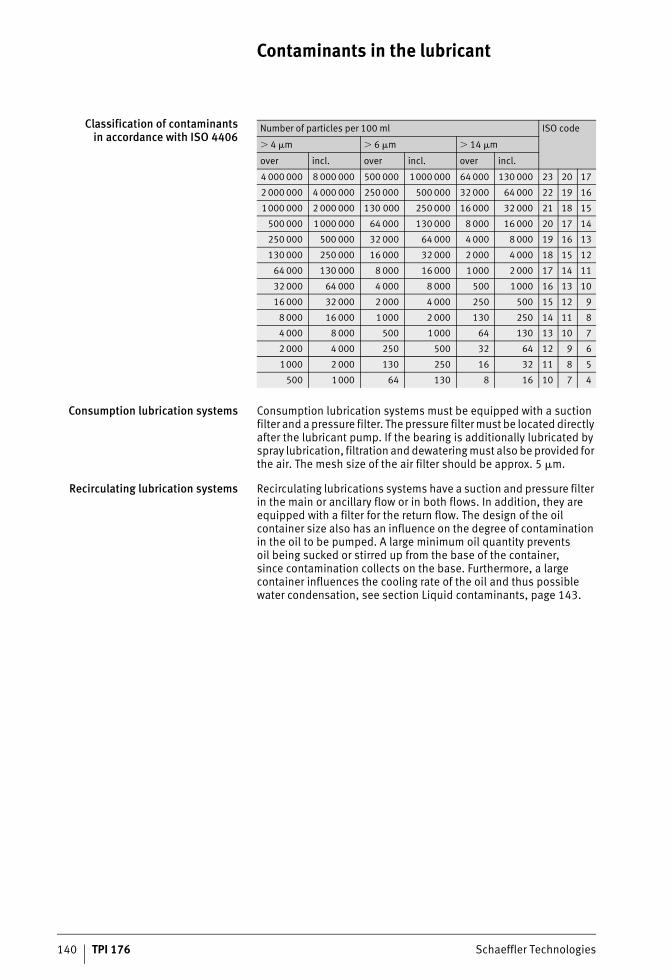
140 TPI 176 Schaeffler Technologies
Contaminants in the lubricant
Classification of contaminantsin accordance with ISO 4406
Consumption lubrication systems Consumption lubrication systems must be equipped with a suction filter and a pressure filter. The pressure filter must be located directly after the lubricant pump. If the bearing is additionally lubricated by spray lubrication, filtration and dewatering must also be provided for the air. The mesh size of the air filter should be approx. 5 �m.
Recirculating lubrication systems Recirculating lubrications systems have a suction and pressure filter in the main or ancillary flow or in both flows. In addition, they are equipped with a filter for the return flow. The design of the oil container size also has an influence on the degree of contamination in the oil to be pumped. A large minimum oil quantity preventsoil being sucked or stirred up from the base of the container,since contamination collects on the base. Furthermore, a large container influences the cooling rate of the oil and thus possible water condensation, see section Liquid contaminants, page 143.
Number of particles per 100 ml ISO code
� 4 �m � 6 �m � 14 �m
over incl. over incl. over incl.
4 000 000 8 000 000 500 000 1000 000 64 000 130 000 23 20 17
2 000 000 4 000 000 250 000 500 000 32 000 64 000 22 19 16
1000 000 2 000 000 130 000 250 000 16 000 32 000 21 18 15
500 000 1000 000 64 000 130 000 8 000 16 000 20 17 14
250 000 500 000 32 000 64 000 4 000 8 000 19 16 13
130 000 250 000 16 000 32 000 2 000 4 000 18 15 12
64 000 130 000 8 000 16 000 1000 2 000 17 14 11
32 000 64 000 4 000 8 000 500 1000 16 13 10
16 000 32 000 2 000 4 000 250 500 15 12 9
8 000 16 000 1000 2 000 130 250 14 11 8
4 000 8 000 500 1000 64 130 13 10 7
2 000 4 000 250 500 32 64 12 9 6
1000 2 000 130 250 16 32 11 8 5
500 1000 64 130 8 16 10 7 4
ST4_3750608907_verunreinigunge.fm Seite 140 Donnerstag, 4. April 2013 10:41 10
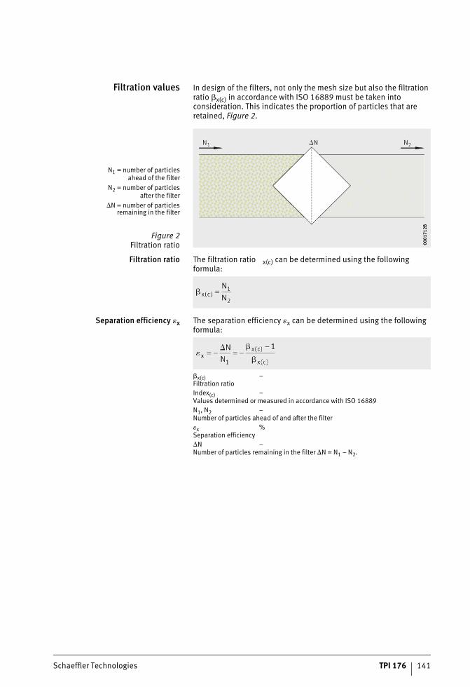
Schaeffler Technologies TPI 176 141
Filtration values In design of the filters, not only the mesh size but also the filtration ratio �x(c) in accordance with ISO 16889 must be taken into consideration. This indicates the proportion of particles that are retained, Figure 2.
Filtration ratio The filtration ratio x(c) can be determined using the following formula:
Separation efficiency �x The separation efficiency �x can be determined using the following formula:
�x(c) –Filtration ratioIndex(c) –Values determined or measured in accordance with ISO 16889N1, N2 –Number of particles ahead of and after the filter�x %Separation efficiency�N –Number of particles remaining in the filter �N = N1 – N2.
N1 = number of particlesahead of the filter
N2 = number of particlesafter the filter
�N = number of particlesremaining in the filter
Figure 2Filtration ratio 00
0171
2B00
0171
2B
ST4_3750608907_verunreinigunge.fm Seite 141 Donnerstag, 4. April 2013 10:42 10
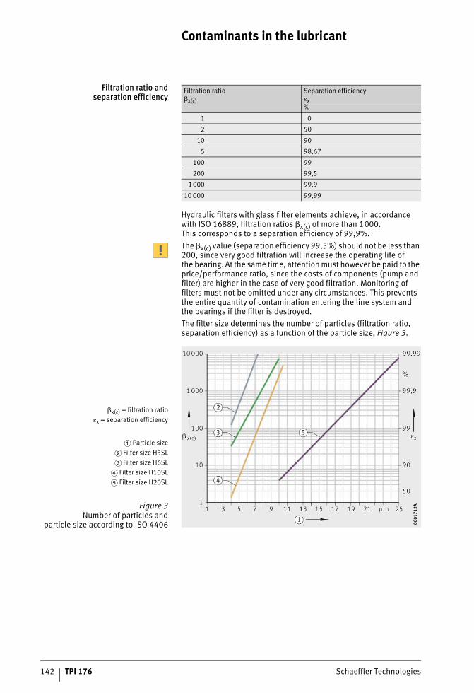
142 TPI 176 Schaeffler Technologies
Contaminants in the lubricant
Filtration ratio andseparation efficiency
Hydraulic filters with glass filter elements achieve, in accordance with ISO 16889, filtration ratios �x(c) of more than 1000. This corresponds to a separation efficiency of 99,9%.The �x(c) value (separation efficiency 99,5%) should not be less than 200, since very good filtration will increase the operating life ofthe bearing. At the same time, attention must however be paid to the price/performance ratio, since the costs of components (pump and filter) are higher in the case of very good filtration. Monitoring of filters must not be omitted under any circumstances. This prevents the entire quantity of contamination entering the line system andthe bearings if the filter is destroyed.The filter size determines the number of particles (filtration ratio, separation efficiency) as a function of the particle size, Figure 3.
Filtration ratio�x(c)
Separation efficiency�x%
1 0
2 50
10 90
5 98,67
100 99
200 99,5
1000 99,9
10 000 99,99
�x(c) = filtration ratio�x = separation efficiency
� Particle size� Filter size H3SL� Filter size H6SL
� Filter size H10SL� Filter size H20SL
Figure 3Number of particles and
particle size according to ISO 4406 0001
712A
0001
712A
ST4_3750608907_verunreinigunge.fm Seite 142 Donnerstag, 4. April 2013 10:42 10
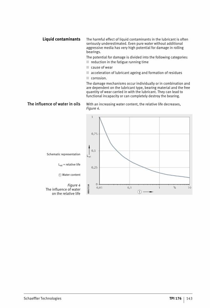
Schaeffler Technologies TPI 176 143
Liquid contaminants The harmful effect of liquid contaminants in the lubricant is often seriously underestimated. Even pure water without additional aggressive media has very high potential for damage in rolling bearings.The potential for damage is divided into the following categories:■ reduction in the fatigue running time■ cause of wear■ acceleration of lubricant ageing and formation of residues■ corrosion.The damage mechanisms occur individually or in combination and are dependent on the lubricant type, bearing material and the free quantity of wear carried in with the lubricant. They can lead to functional incapacity or can completely destroy the bearing.
The influence of water in oils With an increasing water content, the relative life decreases, Figure 4.
Schematic representation
Lrel = relative life
� Water content
Figure 4The influence of water
on the relative life 0001
711A
0001
711A
ST4_3750608907_verunreinigunge.fm Seite 143 Donnerstag, 4. April 2013 10:42 10
144 TPI 176 Schaeffler Technologies
Contaminants in the lubricant
Depending on the composition of the lubricant and the bearing type, a detectable impairment of the fatigue running time can be expected with a water content of or greater than approx. 200 ppm. Due to the mixing effect, the viscosity of the lubricant is reduced. The actual cause of damage is, however, the occasional overrolling of water microdroplets occurring under high pressure and the associated punctures in the lubricant film. With an increasing water content,the number of microdroplets increases and, starting at a certain concentration, the size of the microdroplets also increases. As a result, the probability of overrolling increases. In parallel, a chemical reaction occurs between the water, lubricant and material that additionally impairs the surface.Starting at approximately the same concentration of approx. 300 ppm, there is a rapid increase in the tendency of oils at high temperatures to form residues in the form of sludge, paint or coking. The ageing of the base oils is accelerated and additives andwater are precipitated or their effect is blocked. In addition to the disruption by deposits of the distributor, feed and outlet systems and the blocking of filter elements, the lubrication capability itselfis reduced.At water contents over 1000 ppm, a different damage mechanism comes into play, depending on the oil composition, prior to fatigue. Even before failure due to material ruptures, the bearing functional surfaces undergo wear. The wear progresses, depending on the strain, without negative effects until the function of the bearings is finally disrupted. However, rapid surface spalling and destructionof the bearings is also possible. The bearing type has a significant influence here. High contact pressures and high proportionsof sliding motion will promote damage. A even more severe influence is exerted by the oil type and the additives. The scatter of the tolerable water quantity can, depending on the lubricant, be up toa power of ten.
ST4_3750608907_verunreinigunge.fm Seite 144 Donnerstag, 4. April 2013 10:43 10
Schaeffler Technologies TPI 176 145
If free water is present, there is an increased risk of corrosion.If bearings are at a standstill, water infiltrates the bearing surfaces protected by the anti-corrosion additives. This effect is supported by the capillary action in the narrowing gap between the rolling element and raceway and occurs there first. This leads to harmful rust forma-tion on the materials, which are not normally corrosion-resistant.If these corrosion scars are overrolled, early fatigue will occur.The bearing surfaces are completely destroyed if the free water is not removed. These damage mechanisms occur if water is continuously present in the stated order of magnitude. Water content presentfor part of the time also has high potential for damage but this is difficult to quantify. Water vapourises from lubricant at low tempera-tures. When water enters and exits continuously due to cooling and heating, this causes considerable damage to the oil and also has effects on the rolling bearings. This is the case, for example,when condensation is formed in oil containers during operational shutdown and in vapourisation at operating temperature.
The influenceof water in greases
In grease, water causes structural changes depending on the thick-ener type. There is a risk that the greases will undergo considerable softening. The damage mechanisms are comparable with those in oils. Greases have the advantage that contaminated lubricant does not necessarily enter the contact and does not flow in when water is vapourised. If there is ingress of water, the grease change interval must be shortened in accordance with the quantity of water present. The action of the grease in supporting sealing is applied in labyrinth lubrication. Aggressive substances such as acids, bases or solvents lead to major changes in the chemical/physical key data and princi-pally to lubricant ageing and corrosion. If such contaminants are expected, the compatibility data from lubricant manufacturers must be considered. At points that are not protected from the lubricant, corrosion will occur sooner or later depending on the aggressiveness of the contaminant and destroy the surface.
ST4_3750608907_verunreinigunge.fm Seite 145 Donnerstag, 4. April 2013 10:43 10
146 TPI 176 Schaeffler Technologies
Contaminants in the lubricant
Gaseous contaminants Oils can, depending on the base oil type, dissolve considerable quantities of gases (in general air).
Dissolved air in oil The determining parameters are principally pressure and temperature. The degree of refinement, viscosity and additives exert only an subordinate influence. In principle, the law formulated by Henry/Dalton applies to dissolved gases: under normal conditions (+20 °C, 1013 mbar) mineral oils can dissolve 7 vol. % to 9 vol. %of air. This corresponds to approx. 1% to 2% of oxygen in the oil.The solubility of air in oil increases correspondingly with increasing pressure.The method in accordance with ASTM D 2779 facilitates calculation of the solubility of various gases in mineral oil products. The method in accordance with ASTM D 3827 contains a calculation method that is also valid for synthetic oils.
Finely distributed air in oil In addition to dissolved air, oils can also contain finely distributed air quantities (dispersed phase).The problems in technical plant as a result of these air-in-oil dispersions include:■ cavitation damage■ increase in temperature due to impaired thermal conductivity
capacity and lower oil flow■ more rapid oil ageing due to oxidation and cracking
(splitting of hydrocarbon molecules)■ wear of parts under high strain due to smaller oil film thickness■ blocking of filters.Dispersed air in oil leads to an increase, even if a small increase,in viscosity. As a guide value, 10 vol. % air in oil leads to an increase in viscosity of approx. 15%.
Air release The air release capacity is determined in accordance with DIN 51381. Under defined test conditions, the time is measured in minutes that is required for the release of air bubbles to a proportion of less than 0,2 vol. %. In practice, the air release capacity can be improved by low recirculation rates and thus long dwell times inthe oil storage container. Special design of the inlets in the oil tank and appropriate guide plates allow more rapid escape of small gas bubbles.
ST4_3750608907_verunreinigunge.fm Seite 146 Donnerstag, 4. April 2013 10:43 10
Schaeffler Technologies TPI 176 147
The air release capacity (LAV) of mineral oils is essentially determined by:■ oil viscosity
– the higher the viscosity, the worse the LAV■ oil temperature
– the LAV improves with increasing temperature■ the presence of additives
– additives that reduce the surface tension of the oil will reduce the LAV (ageing products)
■ solid and liquid contaminants.The influence of small gas bubbles in oil on lubricant film formation has not yet been researched adequately. For example, there are no precise findings on the size up to which gas bubbles are overrolled in rolling contacts and metal-to-metal contact then occurs. Theoretical analyses show that passage through the lubricationgap can be substantially ruled out. This is due to the size of the gas bubbles.
Foaming behaviour If gas (air) and oil are actively mixed, a substantially stable foam can form on the surface. If the foam breaks down in a sufficiently short time, hardly any problems will occur. If stable foaming occurs,there may be delivery problems in oil pumps. An oil foam is also strongly compressible. Great care must be taken in the use of foam inhibitors, since the introduction of these additives impairs the air release capacity. Careful handling of the oil (filtration, degassing, water separation, cooling) and the selected of appropriate oils will help to avoid problems in practice. This applies particularly in equip-ment with a relatively large oil volume such as paper machinery or wind turbines.
ST4_3750608907_verunreinigunge.fm Seite 147 Donnerstag, 4. April 2013 10:43 10
148 TPI 176 Schaeffler Technologies
Contaminants in the lubricant
Cleaningof contaminated bearings
All parts that are removed from undamaged original packaging are very clean and do not require cleaning. Cleaning in this case would very probably impair the original condition. Parts that have become contaminated as a result of environmental influences can be cleaned using petroleum ether, petroleum, spirit, dewatering fluids, aqueous, neutral and also alkaline cleaning agents. It must be noted that petroleum, petroleum ether, spirit and dewatering fluids are flammable and alkaline agents are corrosive. The washing process should be carried out using brushes, paint brushes or lint-free cloths.After washing, the parts must be:■ additionally cleaned using a very clean rinsing medium
appropriate to the washing chemicals■ subsequently dried■ protected immediately using preservation in order to prevent
corrosion.Compatibility of the preservation with the lubricant used must be observed. If the bearings contain resinous oil or grease residues, precleaning by mechanical means followed by longer softening with an aqueous, strongly alkaline cleaning agent is recommended.
ST4_3750608907_verunreinigunge.fm Seite 148 Donnerstag, 4. April 2013 10:43 10

Schaeffler Technologies TPI 176 149
ST4_3750608907_verunreinigunge.fm Seite 149 Donnerstag, 4. April 2013 10:43 10
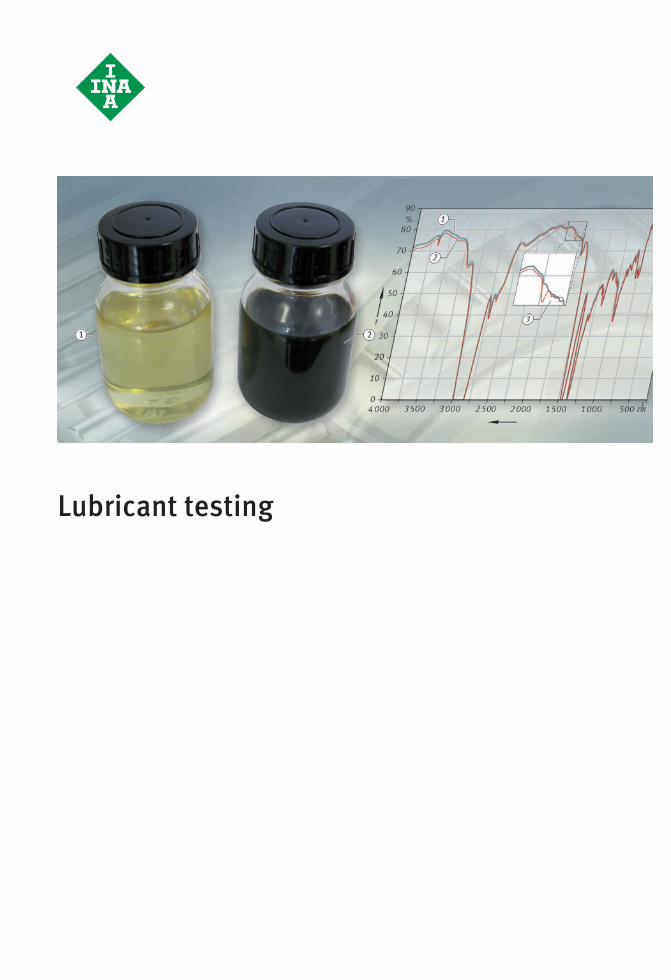
Lubricant testing
#tpi176__en_gb__de.xml_FM8_en_gb.book Seite 150 Donnerstag, 4. April 2013 8:22 08
Schaeffler Technologies TPI 176 151
Page
Lubricant testing
Sensory and analytical testing Sensory lubricant testing ........................................................ 152Odour and colour ............................................................... 152Lubrication effect and consistency...................................... 153
Analytical lubricant testing...................................................... 153Element content ................................................................. 153Infrared spectroscopy......................................................... 154Proportion of solids............................................................ 155Water content .................................................................... 155Viscosimetry ...................................................................... 155
Mechanical-dynamic testing Accelerated test method, element tests, tribometer ................. 157
Rolling bearing test devices .................................................... 157Test rig FE8......................................................................... 158Test rig FE9......................................................................... 160Test rig A2.......................................................................... 161Test rig LFT ......................................................................... 162Test rig AN42...................................................................... 163Test rig WS22 ..................................................................... 164Test rig WS10 ..................................................................... 165
Special tests for specific applications ..................................... 166FE8 paper machinery testing............................................... 166Wind energy 4 stage test .................................................... 166
ST4_3762593547_ivz.fm Seite 151 Donnerstag, 4. April 2013 10:44 10
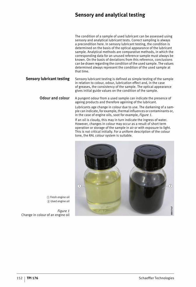
152 TPI 176 Schaeffler Technologies
Sensory and analytical testing
The condition of a sample of used lubricant can be assessed using sensory and analytical lubricant tests. Correct sampling is alwaysa precondition here. In sensory lubricant testing, the condition is determined on the basis of the optical appearance of the lubricant sample. Analytical methods are comparative methods, in which the corresponding data for an unused reference sample must always be known. On the basis of deviations from this reference, conclusions can be drawn regarding the condition of the used sample. The values determined always represent the condition of the used sample at that time.
Sensory lubricant testing Sensory lubricant testing is defined as simple testing of the sample in relation to colour, odour, lubrication effect and, in the caseof greases, the consistency of the sample. The optical appearance gives initial guide values on the condition of the sample.
Odour and colour A pungent odour from a used sample can indicate the presence of ageing products and therefore ageining of the lubricant.Lubricants age change in colour due to use. The darkening of a sam-ple can indicate, for example, thermal influences or contaminants or, in the case of engine oils, soot for example, Figure 1.If an oil is cloudy, this may in turn indicate the ingress of water. However, changes in colour may occur as a result of short term operation or storage of the sample in air or with exposure to light. This is not critical initially. For a uniform description of the colour tone, the RAL colour system is suitable.
� Fresh engine oil� Used engine oil
Figure 1Change in colour of an engine oil 00
0171
4700
0171
47
ST4_3762663691_sensorische_und.fm Seite 152 Donnerstag, 4. April 2013 10:44 10
Schaeffler Technologies TPI 176 153
Lubrication effect andconsistency
Once some experience has been gained, it can be determinedby rubbing a sample between two fingers whether it essentially has a lubrication effect. In addition, it is often possible to detect solid lubricants in this manner.Greases that have been subjected to heavy use or are heavily contaminated will frequently exhibit higher consistency (resistance). This can be explained by a reduced base oil content (for example, through heavy oil loss during operation) or the occurrence of ageing products. Sensory testing can give initial guide values here. In general, it is not possible to make a reliable statement onthe condition of the sample on the basis of sensory testing alone. This can only be achieved by means of suitable analytical methods in the laboratory. Furthermore, sensory testing is subjective andthus dependent on the observer. The results may therefore vary from one observer to another.
Analytical lubricant testing A large number of analytical test methods are available. Selecting which methods are used is based on the relevant application of the sample or on the direction of the investigation, for example towards symptoms of ageing or wear. In many cases, only a limited sample quantity will be available, however, as a result of which it will be necessary to prioritise the test methods.
Element content The element content of a lubricant sample can be determined, for example, by means of optical ICP emission spectrometry (ICP-OES). ICP-OES stands for Inductively Coupled Plasma Optical Emission Spectrometry. The sample is first digested in a suitable solvent by means of microwaves in order to release the chemical compounds. The molecules of the sample are then broken up in an argon plasma and the atomic ions are excited in order to promote light emission. The wavelength emitted is used to identify the element. The intensity of the light emission also indicates the concentration of the relevant element. If the element content of a fresh sample is present asa reference for a lubricant sample, statements can be made about any changes. This includes, for example, the decompositionof certain additive elements or the contamination of the sample by inorganic substances.
ST4_3762663691_sensorische_und.fm Seite 153 Donnerstag, 4. April 2013 10:44 10
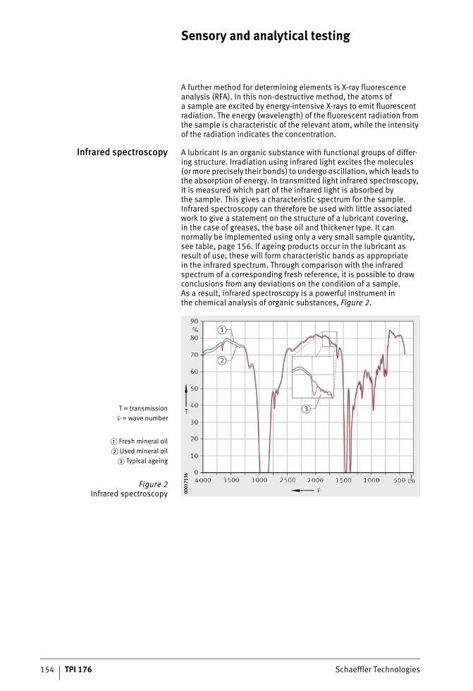
154 TPI 176 Schaeffler Technologies
Sensory and analytical testing
A further method for determining elements is X-ray fluorescence analysis (RFA). In this non-destructive method, the atoms ofa sample are excited by energy-intensive X-rays to emit fluorescent radiation. The energy (wavelength) of the fluorescent radiation from the sample is characteristic of the relevant atom, while the intensity of the radiation indicates the concentration.
Infrared spectroscopy A lubricant is an organic substance with functional groups of differ-ing structure. Irradiation using infrared light excites the molecules (or more precisely their bonds) to undergo oscillation, which leads to the absorption of energy. In transmitted light infrared spectroscopy, it is measured which part of the infrared light is absorbed bythe sample. This gives a characteristic spectrum for the sample. Infrared spectroscopy can therefore be used with little associated work to give a statement on the structure of a lubricant covering,in the case of greases, the base oil and thickener type. It can normally be implemented using only a very small sample quantity, see table, page 156. If ageing products occur in the lubricant as result of use, these will form characteristic bands as appropriatein the infrared spectrum. Through comparison with the infrared spectrum of a corresponding fresh reference, it is possible to draw conclusions from any deviations on the condition of a sample.As a result, infrared spectroscopy is a powerful instrument inthe chemical analysis of organic substances, Figure 2.
T = transmission= wave number
� Fresh mineral oil� Used mineral oil
� Typical ageing
Figure 2Infrared spectroscopy 00
0171
3600
0171
36
ST4_3762663691_sensorische_und.fm Seite 154 Donnerstag, 4. April 2013 10:44 10
Schaeffler Technologies TPI 176 155
Proportion of solids The lubricant probe is digested using a suitable solvent in an ultra-sonic bath and the solution is then filtered off. Filters of different pore sizes are available for this purpose. After drying, the filter is evaluated in both quantitative and qualitative (optical) respects. Detectable particles can, as necessary, be subjected to further investigation in order to determine the origin and effect of the particles. For example, infrared spectroscopy facilitates statements on organic chemistry and energy-dispersive X-ray spectroscopy (EDX) facilitates statements on inorganic chemistry.
Water content Even a small ingress of water or moisture into the lubricant can cause severe damage through corrosion or breakdown of the lubricant film, see section Liquid contaminants, page 143.The Karl-Fischer method allows the water content of a lubricant sample to be determined by means of titration. Comparison withthe water content of a fresh sample gives a statement on any water ingress. It must be noted here that this investigation can only show the water content present at the time. Between the actual ingressof water, taking of the sample and the investigation, at least part of the water may have vapourised from the lubricant. This will be promoted by increased temperature, negative pressure or storage of the sample in an open vessel.
Viscosimetry Oils are subjected to mechanical load during operation. As a result, the molecular chains may be broken, leading to a reduction in viscosity. The viscosity may also be reduced as a result of thinning with a low viscosity fluid such as petrol. On the other hand,the viscosity may be increased by ageing products or contaminants such as soot. A very common method for determining viscosityis Ubbelohde viscosimetry. The method uses the capillary actionof the oil and gives a statement on the kinematic viscosity.A further method is rotational viscosimetry, for example by meansof a Stabinger viscosimeter. These devices determine the dynamic viscosity and density of a lubricant. The kinematic viscosity is calculated and also outputted. Both methods can be used for New-tonian fluids. For non-Newtonian fluids (structurally viscous fluids such as greases), rheology can give statements on the apparent viscosity. In the case of these substances, viscosity is a function of time, shear rate and temperature. For guide values on the minimum quantity required in lubricant testing, see table, page 156.
ST4_3762663691_sensorische_und.fm Seite 155 Donnerstag, 4. April 2013 10:45 10
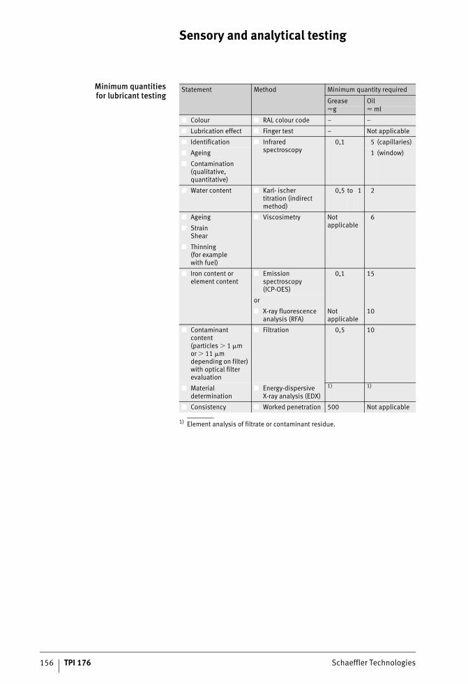
156 TPI 176 Schaeffler Technologies
Sensory and analytical testing
Minimum quantitiesfor lubricant testing
1) Element analysis of filtrate or contaminant residue.
Statement Method Minimum quantity required
Grease Oil�g � ml
■ Colour ■ RAL colour code – –
■ Lubrication effect ■ Finger test – Not applicable
■ Identification ■ Infrared spectroscopy
0,1 5 (capillaries)
■ Ageing 1 (window)
■ Contamination(qualitative, quantitative)
■ Water content ■ Karl- ischer titration (indirect method)
0,5 to 1 2
■ Ageing ■ Viscosimetry Not applicable
6
■ Strain Shear
■ Thinning(for examplewith fuel)
■ Iron content or element content
■ Emission spectroscopy(ICP-OES)
0,1 15
or
■ X-ray fluorescence analysis (RFA)
Not applicable
10
■ Contaminant content(particles � 1 �mor � 11 �m depending on filter) with optical filter evaluation
■ Filtration 0,5 10
■ Material determination
■ Energy-dispersive X-ray analysis (EDX)
1) 1)
■ Consistency ■ Worked penetration 500 Not applicable
ST4_3762663691_sensorische_und.fm Seite 156 Donnerstag, 4. April 2013 10:45 10
Schaeffler Technologies TPI 176 157
Mechanical-dynamic testing
In most cases, rolling bearings are components that are subjectedto the highest mechanical and dynamic loads. The core functions of the relevant application are very often dependent on their reliable function. Continuous progress in technical development, economic optimisation and performance increase leads in the rolling bearing in particular to concentrations of load that must be withstood,not least by the lubricant as a design element.Selecting or developing an optimum lubricant for the relevant application is only possible if such lubricants can be tested, under conditions matching practical use, in relation to characteristicsthat are decisive in terms of function.In contrast to purely substance-based characteristics, which are determined in the classical chemistry laboratory, the functional behaviour of a lubricant in a rolling bearing can, so far, only be tested in the rolling bearing itself.These mechanical-dynamic tests are not a simulation of the actual application. Instead, they are a model of individual functions ofthe lubricant, such as its anti-wear capacity, in the bearing. The tests are thus the basis for assessing the performance of oils and greases. They are carried out on different bearing types and under conditions that reflect the limits of the actual applications that are relevantto failure.
Accelerated test method,element tests, tribometer
Ideally, tests should allow rapid results and incur only low test costs.For example, the following test methods are widely used:■ VKA (Shell four ball test machine)■ pin-on-disc test rig■ Almen-Wieland test machine■ SRV test machine■ two-disc test rig.Some of these methods are used in the development of lubricantsin order to allow rapid and economical determination of changesin characteristics between individual development models or development stages. The correlation of these test methods with actual applications is not, however, sufficient in order to assessthe performance of lubricants in the rolling bearing. For performance tests on oils and greases in rolling bearings, see section Rolling bearing test devices, page 158 and section Special tests for specific applications, page 166.
ST4_3946332555_mechanisch_dyna.fm Seite 157 Donnerstag, 4. April 2013 10:45 10
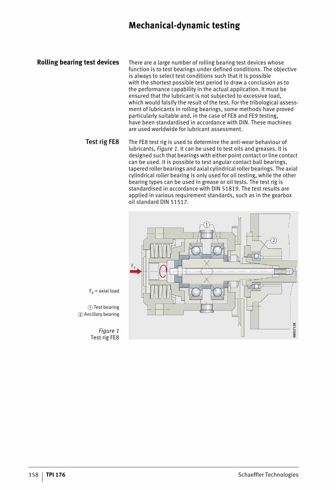
158 TPI 176 Schaeffler Technologies
Mechanical-dynamic testing
Rolling bearing test devices There are a large number of rolling bearing test devices whose function is to test bearings under defined conditions. The objective is always to select test conditions such that it is possiblewith the shortest possible test period to draw a conclusion as tothe performance capability in the actual application. It must be ensured that the lubricant is not subjected to excessive load,which would falsify the result of the test. For the tribological assess-ment of lubricants in rolling bearings, some methods have proved particularly suitable and, in the case of FE8 and FE9 testing,have been standardised in accordance with DIN. These machinesare used worldwide for lubricant assessment.
Test rig FE8 The FE8 test rig is used to determine the anti-wear behaviour of lubricants, Figure 1. It can be used to test oils and greases. It is designed such that bearings with either point contact or line contact can be used. It is possible to test angular contact ball bearings, tapered roller bearings and axial cylindrical roller bearings. The axial cylindrical roller bearing is only used for oil testing, while the other bearing types can be used in grease or oil tests. The test rig is standardised in accordance with DIN 51819. The test results are applied in various requirement standards, such as in the gearboxoil standard DIN 51517.
Fa = axial load
� Test bearing� Ancillary bearing
Figure 1Test rig FE8 00
0171
2800
0171
28
ST4_3946332555_mechanisch_dyna.fm Seite 158 Donnerstag, 4. April 2013 10:45 10
Schaeffler Technologies TPI 176 159
Load range Depending on the requirements of the application, axial loads from 5 kN to 100 kN can be applied. The speed range extends from 7,5 min–1 to 4 500 min–1 (in the special version up to 6 000 min–1). Not all load/speed duty cycles can be run in the test.There are load/speed duty cycles that are appropriate and for which comparative results are presented. In this test method, a very wide range of lubrication regimes can be tested under the same conditions, from extreme mixed friction through moderate mixed friction to a full load-bearing lubricant film. With the axial cylindrical roller bearing, extreme mixed friction and sliding can be generated.
Special version A special version includes a preheating container. This addition makes it possible to conduct special tests for paper machinery and wind energy gearboxes. The oil is contaminated with distilled water or process water before it is fed into the preheating container, passes through the container in a sheet metal cascade device and then reaches the test head. Oil deposits may be formed in the tempered preheating container (depending on the type of testing,at +100 °C or +120 °C). In addition to the anti-wear protection bythe oil, these deposits and the filterability of the oil are assessed.
ST4_3946332555_mechanisch_dyna.fm Seite 159 Donnerstag, 4. April 2013 10:45 10
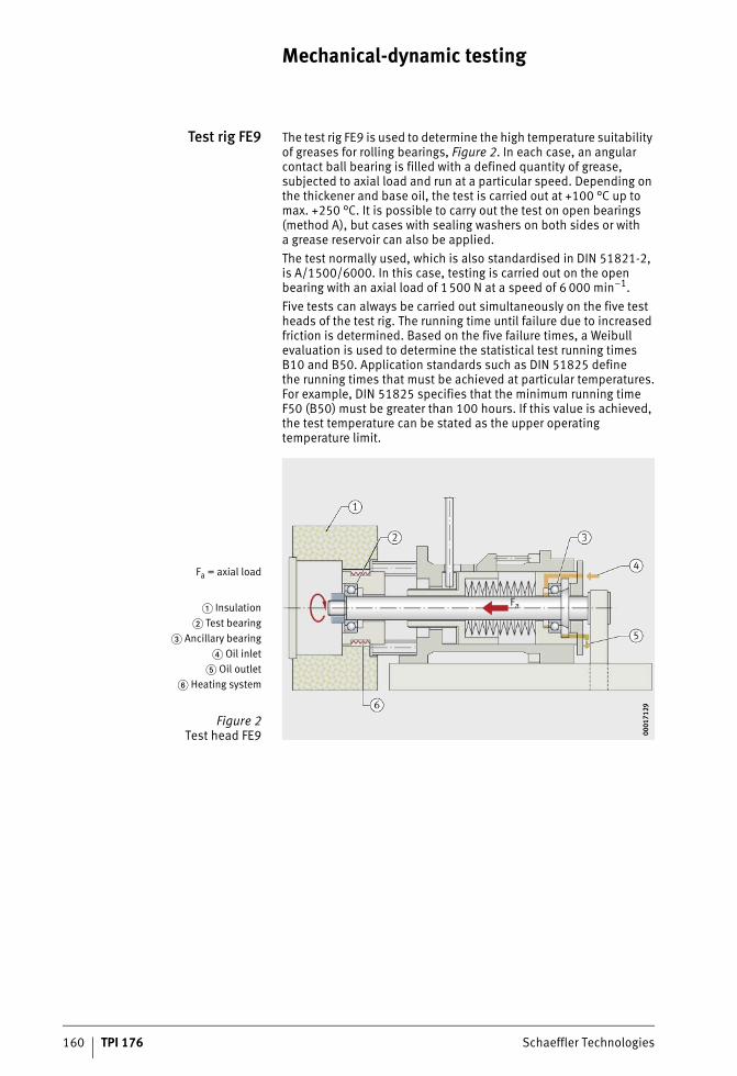
160 TPI 176 Schaeffler Technologies
Mechanical-dynamic testing
Test rig FE9 The test rig FE9 is used to determine the high temperature suitability of greases for rolling bearings, Figure 2. In each case, an angular contact ball bearing is filled with a defined quantity of grease, subjected to axial load and run at a particular speed. Depending on the thickener and base oil, the test is carried out at +100 °C up to max. +250 °C. It is possible to carry out the test on open bearings (method A), but cases with sealing washers on both sides or witha grease reservoir can also be applied.The test normally used, which is also standardised in DIN 51821-2, is A/1500/6000. In this case, testing is carried out on the open bearing with an axial load of 1500 N at a speed of 6 000 min–1.Five tests can always be carried out simultaneously on the five test heads of the test rig. The running time until failure due to increased friction is determined. Based on the five failure times, a Weibull evaluation is used to determine the statistical test running times B10 and B50. Application standards such as DIN 51825 define the running times that must be achieved at particular temperatures.For example, DIN 51825 specifies that the minimum running time F50 (B50) must be greater than 100 hours. If this value is achieved, the test temperature can be stated as the upper operating temperature limit.
Fa = axial load
� Insulation� Test bearing
� Ancillary bearing� Oil inlet
� Oil outlet� Heating system
Figure 2Test head FE9 00
0171
2900
0171
29
ST4_3946332555_mechanisch_dyna.fm Seite 160 Donnerstag, 4. April 2013 10:45 10
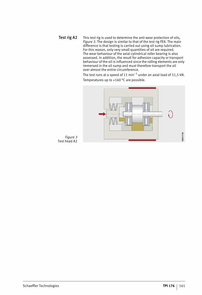
Schaeffler Technologies TPI 176 161
Test rig A2 This test rig is used to determine the anti-wear protection of oils, Figure 3. The design is similar to that of the test rig FE8. The main difference is that testing is carried out using oil sump lubrication.For this reason, only very small quantities of oil are required.The wear behaviour of the axial cylindrical roller bearing is also assessed. In addition, the result for adhesion capacity or transport behaviour of the oil is influenced since the rolling elements are only immersed in the oil sump and must therefore transport the oilover almost the entire circumference.The test runs at a speed of 11 min–1 under an axial load of 51,5 kN.Temperatures up to +160 °C are possible.
Figure 3Test head A2 00
0171
3A00
0171
3A
ST4_3946332555_mechanisch_dyna.fm Seite 161 Donnerstag, 4. April 2013 10:46 10
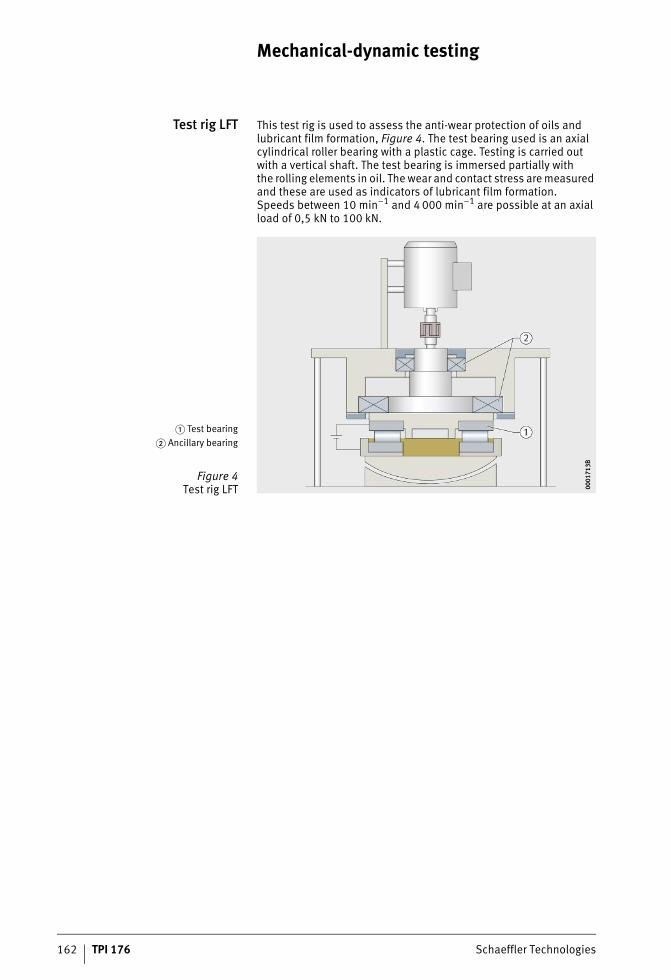
162 TPI 176 Schaeffler Technologies
Mechanical-dynamic testing
Test rig LFT This test rig is used to assess the anti-wear protection of oils and lubricant film formation, Figure 4. The test bearing used is an axial cylindrical roller bearing with a plastic cage. Testing is carried out with a vertical shaft. The test bearing is immersed partially withthe rolling elements in oil. The wear and contact stress are measured and these are used as indicators of lubricant film formation.Speeds between 10 min–1 and 4 000 min–1 are possible at an axial load of 0,5 kN to 100 kN.
� Test bearing� Ancillary bearing
Figure 4Test rig LFT 00
0171
3B00
0171
3B
ST4_3946332555_mechanisch_dyna.fm Seite 162 Donnerstag, 4. April 2013 10:46 10
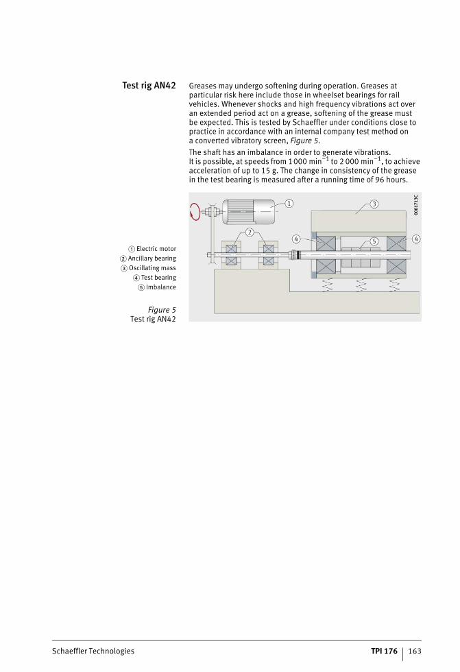
Schaeffler Technologies TPI 176 163
Test rig AN42 Greases may undergo softening during operation. Greases at particular risk here include those in wheelset bearings for rail vehicles. Whenever shocks and high frequency vibrations act over an extended period act on a grease, softening of the grease mustbe expected. This is tested by Schaeffler under conditions close to practice in accordance with an internal company test method ona converted vibratory screen, Figure 5.The shaft has an imbalance in order to generate vibrations.It is possible, at speeds from 1000 min–1 to 2 000 min–1, to achieve acceleration of up to 15 g. The change in consistency of the greasein the test bearing is measured after a running time of 96 hours.
� Electric motor� Ancillary bearing� Oscillating mass
� Test bearing� Imbalance
Figure 5Test rig AN42
0001
713C
0001
713C
ST4_3946332555_mechanisch_dyna.fm Seite 163 Donnerstag, 4. April 2013 10:46 10
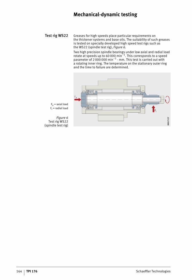
164 TPI 176 Schaeffler Technologies
Mechanical-dynamic testing
Test rig WS22 Greases for high speeds place particular requirements onthe thickener systems and base oils. The suitability of such greases is tested on specially developed high speed test rigs such asthe WS22 (spindle test rig), Figure 6.Two high precision spindle bearings under low axial and radial load rotate at speeds up to 60 000 min–1. This corresponds to a speed parameter of 2 000 000 min–1 · mm. This test is carried out witha rotating inner ring. The temperature on the stationary outer ring and the time to failure are determined.
Fa = axial loadFr = radial load
Figure 6Test rig WS22
(spindle test rig) 0001
7137
0001
7137
ST4_3946332555_mechanisch_dyna.fm Seite 164 Donnerstag, 4. April 2013 10:47 10
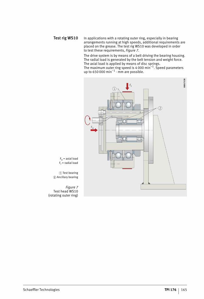
Schaeffler Technologies TPI 176 165
Test rig WS10 In applications with a rotating outer ring, especially in bearing arrangements running at high speeds, additional requirements are placed on the grease. The test rig WS10 was developed in orderto test these requirements, Figure 7.The drive system is by means of a belt driving the bearing housing. The radial load is generated by the belt tension and weight force.The axial load is applied by means of disc springs.The maximum outer ring speed is 4 000 min–1. Speed parametersup to 650 000 min–1 · mm are possible.
Fa = axial loadFr = radial load
� Test bearing� Ancillary bearing
Figure 7Test head WS10
(rotating outer ring)
0001
7138
0001
7138
ST4_3946332555_mechanisch_dyna.fm Seite 165 Donnerstag, 4. April 2013 10:47 10
166 TPI 176 Schaeffler Technologies
Mechanical-dynamic testing
Special testsfor specific applications
FE8 paper machinery testing This test models the environmental conditions of the dry sectionin a paper machine. The method is based on the test rig FE8 in the special version with a preheating container, see section Test rig FE8, page 158. Operating conditions close to practice are selected for this test.For paper machinery testing, these are:■ speed 750 min–1
axial load 20 kNtemperature 140 °C at the outlet of the preheating containerrunning time 500 hoursaddition of synthetic process water.
Wind energy 4 stage test In the case of this test method, an attempt was made to modelall the damage mechanisms then known in wind energy gearboxes. The objective is to identify unsuitable lubricants at an early stage through these four tests.
Stage 1Anti-wear protection under extreme
mixed friction
The test carried out here is based on a requirement similar to that on type CLP gearbox oils in accordance with DIN 51517 on the test rig FE8. The difference here is that a higher axial load of 100 kN is used instead of 80 kN. This test is carried out in the extreme mixed friction range and takes account not only of the requirements on rolling element wear but also the occurrence of rippling and other surface damage.Test conditions:
speed 7,5 min–1
axial load 100 kNtemperature +80 °Crunning time 80 hours.
Stage 2Fatigue under moderate
mixed friction
Testing is carried out on the test rig FE8 under moderate mixed friction conditions. Test bearings F-562831 with a plastic cage are used here. This cage differs from the screwed together plastic cage previously used in that it has two fewer pockets. The test load was therefore reduced from 100 kN to 90 kN. After a running time of 800 hours, there must be no rippling or pitting.Test conditions:
speed 75 min–1
axial load 90 kNtemperature +70 °Crunning time 800 hours.
ST4_3946332555_mechanisch_dyna.fm Seite 166 Donnerstag, 4. April 2013 10:48 10
Schaeffler Technologies TPI 176 167
Stage 3Additive reactions under
EHD conditions
Testing is carried out under EHD conditions on the test rig L11.The aggressiveness of the additives is tested. After a running timeof 700 hours, there must be no failures in the test bearings 6206 that were caused by additives. Since the required test running timeis a multiple of the calculated bearing life, it is still possible that failures will occur that were not caused by the lubricant.Test conditions:■ speed 9 000 min–1
■ radial load 8,5 kN■ running time 700 hours.
Stage 4Oil behaviour
at increased temperature andwith addition of water
In many applications, gearboxes are subjected to moisture bythe ambient conditions or condensation forms in the gearbox.This moisture can lead to additive reactions that, in conjunction with high temperatures, can cause formation of residues and filtration problems. At the same time, moisture has a negative effect onthe lubricant film and precipation reactions of the additives can lead to unfavourable reaction layers in the bearing. In Stage 4, an attempt is made to model these aspects in a single test. The test rig FE8with the preheating container already described is used here.Test conditions:■ speed 750 min–1
■ axial load 60 kN■ temperature +100 °C at the outlet of the preheating container■ running time 600 hours.Assessment is carried out on achieving the running time of 600 hours without bearing failure, formation of residues,any occurrence of filter blockage or rolling element wear.
ST4_3946332555_mechanisch_dyna.fm Seite 167 Donnerstag, 4. April 2013 10:48 10
Storage and handling
#tpi176__en_gb__de.xml_FM8_en_gb.book Seite 168 Donnerstag, 4. April 2013 8:22 08
Schaeffler Technologies TPI 176 169
Page
Storage and handling
Storage Storage of rolling bearings ...................................................... 170Storage conditions ............................................................. 170Storage periods.................................................................. 171
Storage of Arcanol rolling bearing greases............................... 171Storage conditions ............................................................. 171Storage periods.................................................................. 171
Handling Measures to be taken after openingthe original packaging ............................................................ 172
Follow-on preservation............................................................ 172
Manual handling of rolling bearings ........................................ 172
Washing out of rolling bearings ............................................... 172
Mixing of anti-corrosion oil with grease ................................... 172
ST4_3959116427_ivz.fm Seite 169 Donnerstag, 4. April 2013 10:49 10
170 TPI 176 Schaeffler Technologies
Storage
Storage of rolling bearings The performance capability of modern rolling bearings lies at the boundaries of what is technically achievable. Not only the materials but also the dimensional accuracies, tolerances, surface quality values and lubrication are optimised for maximum function.Even the slightest deviations in functional areas, for example asa result of corrosion, can impair the performance capability.In order to realise the full performance capability of rolling bearings, it is essential to match the anti-corrosion protection, packaging, storage and handling to each other. Anti-corrosion protection and packaging are components of the product. They are optimised by Schaeffler as part of the process of preserving all the characteristics of the product at the same time. In addition to protection of the surfaces against corrosion, other important characteristics include emergency running lubrication, friction, lubricant compatibility, noise behaviour, resistance to ageing and compatibility with rolling bearing components (brass cage, plastic cage, elastomer seal).Anti-corrosion protection and packaging are matched by Schaeffler to these characteristics. The precondition here is the use of storage that is normal for high quality goods.
Storage conditions The basic precondition for storage is a closed storage room in which no aggressive media of any sort may have an effect, such as exhaust from vehicles or gases, mist or aerosols of acids, alkalis or salts. Direct sunlight must also be avoided.The storage temperature should be as constant as possible andthe humidity as low as possible. Jumps in temperature and increased humidity lead to condensation.The following conditions must be fulfilled:■ frost-free storage at a minimum temperature of +5 °C
(secure prevention of hoarfrost formation,permissible up to 12 hours per day down to +2 °C)
■ maximum temperature +40 °C(prevention of excessive run-off of anti-corrosion oils)
■ relative humidity less than 65%(with changes in temperature,permissible up to max. 12 hours per day up to 70%).
The temperature and humidity must be continuously monitored.
ST4_3959192971_aufbewahrung.fm Seite 170 Donnerstag, 4. April 2013 10:49 10
Schaeffler Technologies TPI 176 171
Storage periods Rolling bearings should not be stored for longer than 3 years.This applies both to open and to greased rolling bearings with sealing shields or washers. In particular, greased rolling bearings should not be stored for too long, since the chemical-physical behav-iour of greases may change during storage. Even if the minimum performance capacity remains, the safety reserves of the grease may have diminished. In general, rolling bearings can be used even after their permissible storage period has been exceeded if the storage conditions during storage and transport were observed. If the storage periods are exceeded, it is recommended that the bearing should be checked for corrosion, the condition of the anti-corrosion oil and where appropriate the condition of the grease before it is used.
Storage of Arcanol rollingbearing greases
Storage conditions The applicable storage conditions for rolling bearing greases arethe same as those for rolling bearings. The precondition is always that the Arcanol rolling bearing grease is stored in closed, completely filled original containers.
Storage periods If the storage conditions are fulfilled, Arcanol rolling bearing greases can be stored in their closed original container without loss of perfor-mance for a maximum of 3 years. As in the case of rolling bearings, the permissible storage period should not be seen as a rigid limit. Rolling bearing greases are mixtures of oil, thickener and additives. Such mixtures of liquid and solid substances do not have unlimited stability but can rather be described as being in a metastable state. During storage, their chemical-physical characteristics may change and they should therefore be used up as soon as possible. If there is any doubt when using older greases, it is recommended that random sample checking of chemical-physical characteristics should be carried out to determine any changes in the grease. It is therefore not possible to state storage periods for containers that have been opened. If containers are to be stored after opening, the grease surface should always be brushed flat, the container should be sealed airtight and it should be stored such that the empty spaceis upwards. High temperatures should be avoided in all cases.For checking of older greases, Schaeffler can provide assistanceas a service for risk assessment covering further storage or use.
ST4_3959192971_aufbewahrung.fm Seite 171 Donnerstag, 4. April 2013 10:49 10
172 TPI 176 Schaeffler Technologies
Handling
Measures to be takenafter opening the original
packaging
The packaging is a component of the anti-corrosion protectionof rolling bearings. Rolling bearings should always remain in their original packaging until immediately before mounting. Once the original packaging has been opened, there is an increased risk of corrosion due to humidity and particles that reach the steel surface. If rolling bearings must be removed from their packaging before they are ultimately used, they must always be covered and stored in conditions of the lowest possible humidity. Protection can be provided either by reusing the original packaging or by means ofa similar polyethylene or polypropylene film.
Follow-on preservation If the anti-corrosion oil is removed from the steel surface, it is recommended that follow-on preservation should be used inthe form of anti-corrosion oil, VCI paper or VCI film, depending on the type of lubrication to be used subsequently (VCI = Volatile Corrosion Inhibitor). Lubricants with a mineral oil base are compatible with practically all conventional anti-corrosion oils, such as Schaeffler Arcanol Anticorrosion Oil, see section Mixing of anti-corrosion oil with grease.
Manual handlingof rolling bearings
Rolling bearings should not be touched with bare hands,since fingermarks may remain on the steel surface that lead toan increased risk of corrosion at these points. Furthermore,some people may have an allergic reaction to mineral oil products. The wearing of gloves is strongly recommended.
Washing outof rolling bearings
If rolling bearings must be washed out in order to remove anti- corrosion oil or an existing greasing, the dry rolling bearings are then at extremely high risk of corrosion, see section Cleaning of contami-nated bearings, page 148. Relubrication is necessary immediately.
Mixingof anti-corrosion oil
with grease
Small proportions of anti-corrosion oil are compatible with practi-cally all greases based on mineral oil. The quantity of anti-corrosion oil should be max. 8% of the lubricant quantity. This excludes greases that contain bentonite as a thickener. These may be softened or in extreme cases liquified by the anti-corrosion additives. Greases with a synthetic oil base are not generally compatible with anti-corrosion oils based on mineral oil. In this case, anti-corrosion protection must be provided by means of VCI paper, VCI film or an anti-corrosion oil matched to the specific lubricant together with appropriate packaging (VCI = Volatile Corrosion Inhibitor).
ST4_3959329163_handhabung.fm Seite 172 Donnerstag, 4. April 2013 10:49 10

Schaeffler Technologies TPI 176 173
ST4_3959329163_handhabung.fm Seite 173 Donnerstag, 4. April 2013 10:49 10
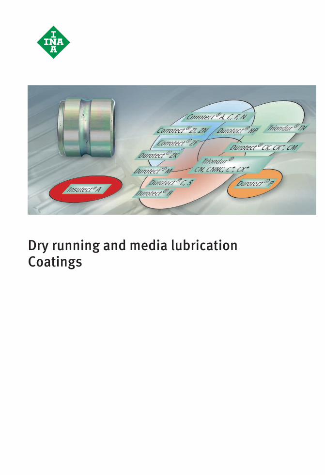
Dry running and media lubricationCoatings
#tpi176__en_gb__de.xml_FM8_en_gb.book Seite 174 Donnerstag, 4. April 2013 8:22 08
Schaeffler Technologies TPI 176 175
Page
Dry running and media lubrication Coatings
Dry running andmedia lubrication
Bearing optimisation .............................................................. 176High performance steels with coatings................................ 176High temperature plastics .................................................. 177Ceramics............................................................................ 178
Wear resistance ...................................................................... 179
Coatings Development centre for surface technology ............................. 181
Use of coatings ....................................................................... 181
Types of coatings .................................................................... 181
Examples................................................................................ 182 Protection against corrosion and fretting corrosion ............. 182Protection against wear, friction and slippage damage........ 184
ST4_3959392139_ivz.fm Seite 175 Donnerstag, 4. April 2013 10:50 10
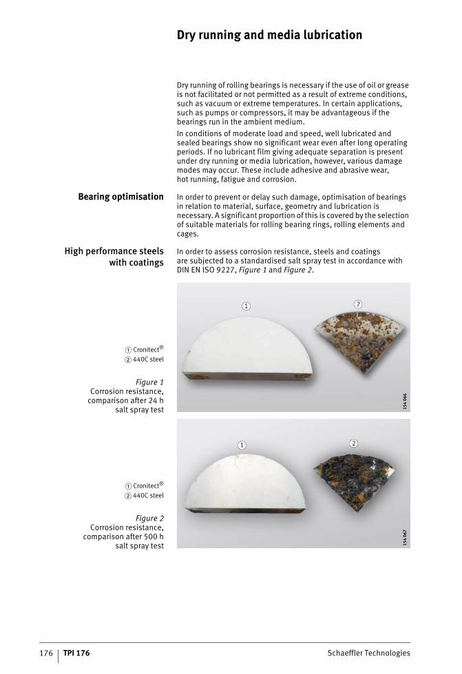
176 TPI 176 Schaeffler Technologies
Dry running and media lubrication
Dry running of rolling bearings is necessary if the use of oil or grease is not facilitated or not permitted as a result of extreme conditions, such as vacuum or extreme temperatures. In certain applications, such as pumps or compressors, it may be advantageous if the bearings run in the ambient medium.In conditions of moderate load and speed, well lubricated and sealed bearings show no significant wear even after long operating periods. If no lubricant film giving adequate separation is present under dry running or media lubrication, however, various damage modes may occur. These include adhesive and abrasive wear,hot running, fatigue and corrosion.
Bearing optimisation In order to prevent or delay such damage, optimisation of bearings in relation to material, surface, geometry and lubrication is necessary. A significant proportion of this is covered by the selection of suitable materials for rolling bearing rings, rolling elements and cages.
High performance steelswith coatings
In order to assess corrosion resistance, steels and coatingsare subjected to a standardised salt spray test in accordance with DIN EN ISO 9227, Figure 1 and Figure 2.
� Cronitect®
� 440C steel
Figure 1Corrosion resistance,
comparison after 24 hsalt spray test 15
4 06
615
4 06
6
� Cronitect®
� 440C steel
Figure 2Corrosion resistance,
comparison after 500 hsalt spray test 15
4 06
715
4 06
7
ST4_4019241995_trockenlauf_und.fm Seite 176 Donnerstag, 4. April 2013 10:50 10
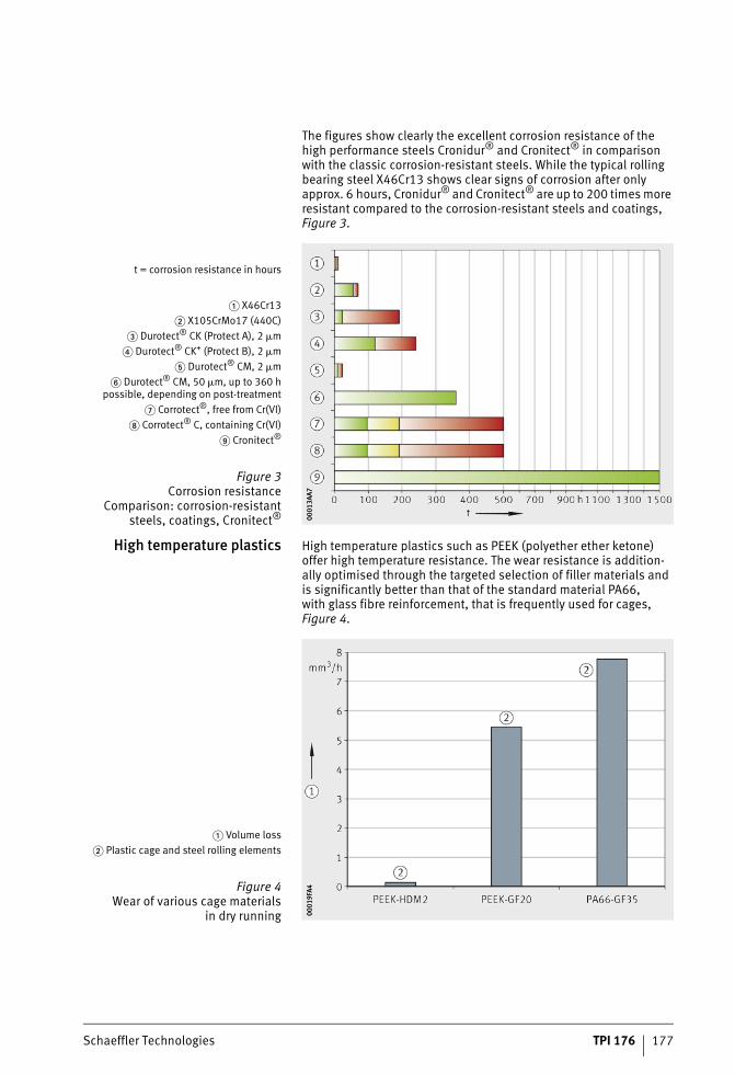
Schaeffler Technologies TPI 176 177
The figures show clearly the excellent corrosion resistance of the high performance steels Cronidur® and Cronitect® in comparison with the classic corrosion-resistant steels. While the typical rolling bearing steel X46Cr13 shows clear signs of corrosion after only approx. 6 hours, Cronidur® and Cronitect® are up to 200 times more resistant compared to the corrosion-resistant steels and coatings, Figure 3.
High temperature plastics High temperature plastics such as PEEK (polyether ether ketone) offer high temperature resistance. The wear resistance is addition-ally optimised through the targeted selection of filler materials and is significantly better than that of the standard material PA66,with glass fibre reinforcement, that is frequently used for cages, Figure 4.
t = corrosion resistance in hours
� X46Cr13� X105CrMo17 (440C)
� Durotect® CK (Protect A), 2 �m� Durotect® CK+ (Protect B), 2 �m
� Durotect® CM, 2 �m� Durotect® CM, 50 �m, up to 360 h
possible, depending on post-treatment� Corrotect®, free from Cr(VI)
Corrotect® C, containing Cr(VI) Cronitect®
Figure 3Corrosion resistance
Comparison: corrosion-resistantsteels, coatings, Cronitect® 00
013A
A700
013A
A7
� Volume loss� Plastic cage and steel rolling elements
Figure 4Wear of various cage materials
in dry running 0001
9FA4
0001
9FA4
ST4_4019241995_trockenlauf_und.fm Seite 177 Donnerstag, 4. April 2013 10:50 10
178 TPI 176 Schaeffler Technologies
Dry running and media lubrication
Polyether ether ketone is a partially crystalline material that is highly resistant even at high temperatures to chemicals as well as organic and inorganic fluids, see table. PEEK is highly suitable for rolling bearing cages, end pieces of linear guidance systems and tyres on track rollers.
Resistance of PEEK cagesin cleaning agents
Ceramics Ceramic has become firmly established as an important groupof materials for rolling bearing components. Since this material has a range of excellent characteristics, rolling elements made from silicon nitride Si3N4 are used with increasing frequency in combination with coatings, special materials or for very specific application requirements.Due to the tribological characteristics of the ceramic/steel material pair, the wear resistance is significantly higher than that of a steel/steel pair. In combination with the highly wear-resistant high performance steels Cronidur® and Cronitect® in particular, a long bearing operating life is achieved with ceramic rolling elements under conditions of dry running or media exposure.
Medium Max. chloride concentration
Max. concentration
Temperature Resistant
mg/l + °C
Sodiumhydroxide solutionNaOH
500 5% 90 Yes
Phosphoric acidH3PO4
200 5% 90
Nitric acidHNO3
200 5% 90
Sulphuric acidH2SO4
150 1,5% 60
Peracetic acid(Aseptic)(Aseptic)
10055
500 mg/l2 000 mg/l4 000 mg/l
406060
Monobromoacetic acid or mono-chloroacetic acid
100 1% mixed with each of 1%:H3PO4, HNO3, H2SO4
30
NaOH + NaOCIChloralkaline cleaner
300 5% 70
SodiumhypochloriteNaOCI
300 300 mg/lactive chlorine
60
20
Hot water 100 – 125
Steamapprox. 0,5 bar
100 – 110
Ozone 80 3 mg/l 30
ST4_4019241995_trockenlauf_und.fm Seite 178 Donnerstag, 4. April 2013 10:51 10
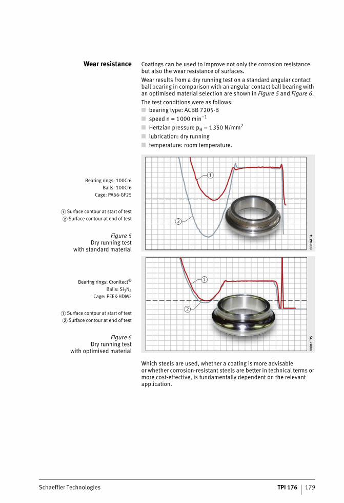
Schaeffler Technologies TPI 176 179
Wear resistance Coatings can be used to improve not only the corrosion resistance but also the wear resistance of surfaces.Wear results from a dry running test on a standard angular contact ball bearing in comparison with an angular contact ball bearing with an optimised material selection are shown in Figure 5 and Figure 6.The test conditions were as follows:■ bearing type: ACBB 7205-B■ speed n = 1000 min–1
■ Hertzian pressure pH = 1350 N/mm2
■ lubrication: dry running■ temperature: room temperature.
Which steels are used, whether a coating is more advisableor whether corrosion-resistant steels are better in technical terms or more cost-effective, is fundamentally dependent on the relevant application.
Bearing rings: 100Cr6Balls: 100Cr6
Cage: PA66-GF25
� Surface contour at start of test� Surface contour at end of test
Figure 5Dry running test
with standard material 0001
6E34
0001
6E34
Bearing rings: Cronitect®
Balls: Si3N4Cage: PEEK-HDM2
� Surface contour at start of test� Surface contour at end of test
Figure 6Dry running test
with optimised material 0001
6E35
0001
6E35
ST4_4019241995_trockenlauf_und.fm Seite 179 Donnerstag, 4. April 2013 10:51 10
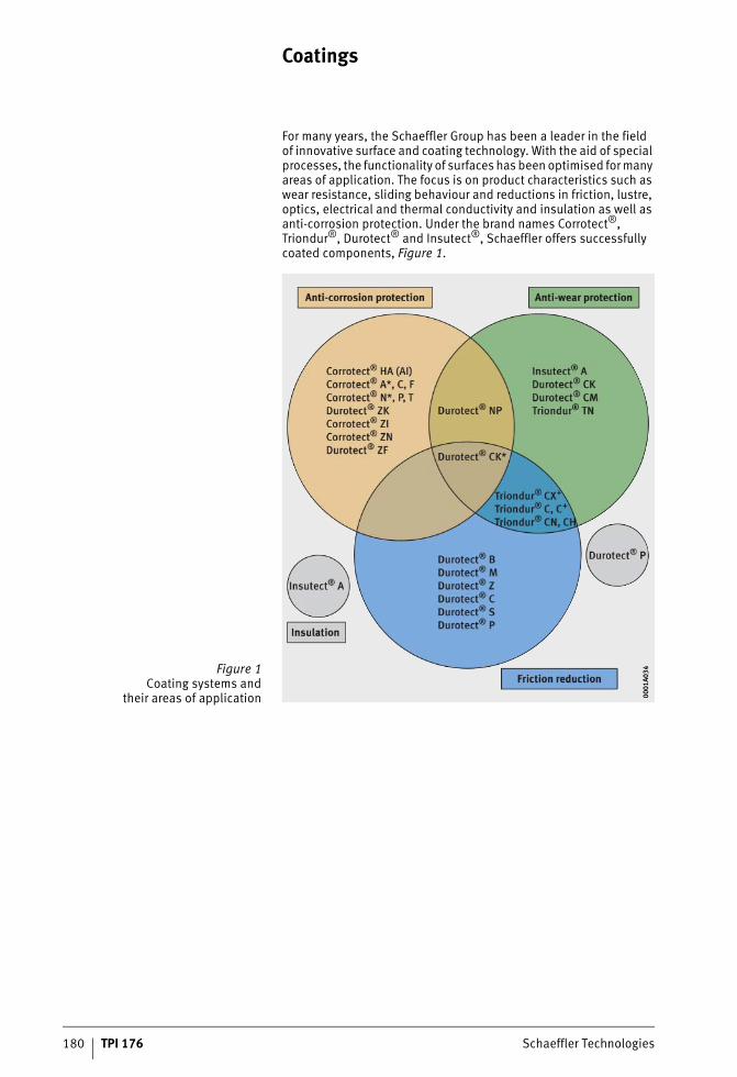
180 TPI 176 Schaeffler Technologies
Coatings
For many years, the Schaeffler Group has been a leader in the fieldof innovative surface and coating technology. With the aid of special processes, the functionality of surfaces has been optimised for many areas of application. The focus is on product characteristics such as wear resistance, sliding behaviour and reductions in friction, lustre, optics, electrical and thermal conductivity and insulation as well as anti-corrosion protection. Under the brand names Corrotect®, Triondur®, Durotect® and Insutect®, Schaeffler offers successfully coated components, Figure 1.
Figure 1Coating systems and
their areas of application 0001
A034
0001
A034
ST4_3959729163_beschichtungen.fm Seite 180 Donnerstag, 4. April 2013 10:52 10
Schaeffler Technologies TPI 176 181
Development centrefor surface technology
With its development centre for surface technology, the Schaeffler Group has created further conditions and possibilities for the successful implementation in practice of theoretical approaches to optimised products. The portfolio of the surface technology centre includes all stages and capacities, from the development of application-oriented coating systems through to volume production. Coating development is carried out on equipment which is equi-valent to that in the production plants, so that the transfer to volume production can be carried out in a rapid and robust manner.With the surface technology centre, development engineers at Schaeffler now have access to equipment and capacity that opens up new possibilities, especially in the combination of various processes and materials.
Use of coatings Bearings and precision components from the Schaeffler Group offer high performance capacity and a long operating life. They provide the user with thoroughly developed and economical solutions for the large majority of requirements. Nevertheless, operating conditions sometimes occur that are beyond the limits of the standard designs. In such cases, one of the very wide range of coatings availablecan be a solution to the task of increasing the operating life ofa component.Coatings are used in the following cases:■ for anti-corrosion protection and the prevention of fretting
corrosion■ for the reduction of wear, particularly under mixed friction,
the improvement of friction behaviour and the prevention of slippage damage
■ as insulation in order to prevent the passage of current.
Types of coatings Coatings are applied to the surfaces of components without thermo-chemical diffusion taking place between the coating and the base material. In the Schaeffler Group, a large number of coatings are used. They are applied by a wide variety of methods and give widely differing advantages for the component. They should always be individually matched to the mounting situation. In many cases, it is sufficient to coat only one of the components in rolling contact or only a part thereof. The table Coating systems, page 186 gives an overview of the coatings used at Schaeffler, arranged according to the main areas of use. The features, advantages and benefits are given for each type of coating. Specific applications and references are presented in detail in TPI 186.
ST4_3959729163_beschichtungen.fm Seite 181 Donnerstag, 4. April 2013 10:52 10
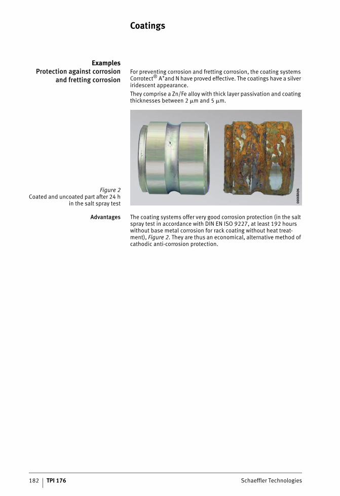
182 TPI 176 Schaeffler Technologies
Coatings
ExamplesProtection against corrosion
and fretting corrosionFor preventing corrosion and fretting corrosion, the coating systems Corrotect® A+and N have proved effective. The coatings have a silver iridescent appearance.They comprise a Zn/Fe alloy with thick layer passivation and coating thicknesses between 2 �m and 5 �m.
Advantages The coating systems offer very good corrosion protection (in the salt spray test in accordance with DIN EN ISO 9227, at least 192 hours without base metal corrosion for rack coating without heat treat-ment), Figure 2. They are thus an economical, alternative method of cathodic anti-corrosion protection.
Figure 2Coated and uncoated part after 24 h
in the salt spray test 0000
BA96
0000
BA96
ST4_3959729163_beschichtungen.fm Seite 182 Donnerstag, 4. April 2013 10:52 10
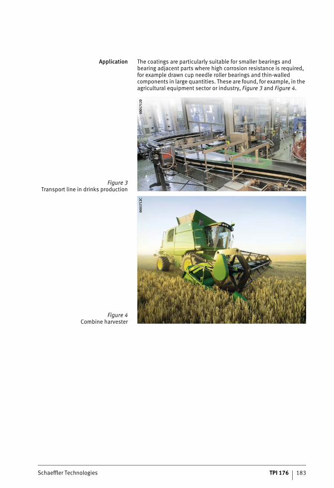
Schaeffler Technologies TPI 176 183
Application The coatings are particularly suitable for smaller bearings and bearing adjacent parts where high corrosion resistance is required, for example drawn cup needle roller bearings and thin-walled components in large quantities. These are found, for example, in the agricultural equipment sector or industry, Figure 3 and Figure 4.
Figure 3Transport line in drinks production
0001
712D
0001
712D
Figure 4Combine harvester
0001
712C
0001
712C
ST4_3959729163_beschichtungen.fm Seite 183 Donnerstag, 4. April 2013 10:53 10

184 TPI 176 Schaeffler Technologies
Coatings
Protection against wear,friction and slippage damage
For the reduction of wear, friction and slippage damage, the coating systems Triondur® C, C+, CX+ (PVD/(PA)CVD hard material layers) have proved effective. The coatings are anthracite to black in colour and have a hardness of more than 1000 HV, Figure 5.They comprise multi-layer, amorphous, hydrogen-containing carbon layers that are doped with metals or non-metals. They have a smooth surface structure and a thickness of 0,5 �m to 4 �m.
Advantages Friction in the dry state between the coating and steel is up to 80% lower in comparison with a steel/steel combination. The low friction value is favourable particularly in cases of adhesive wear.The coating is characterised by high wear resistance in the mixed friction range. The high hardness also contributes high wear resistance. The coatings are ideally suited in conditions of slippage damage and for large bearing components.
Figure 5Tappet with Triondur® CX+ 00
0171
2E00
0171
2E
ST4_3959729163_beschichtungen.fm Seite 184 Donnerstag, 4. April 2013 10:54 10
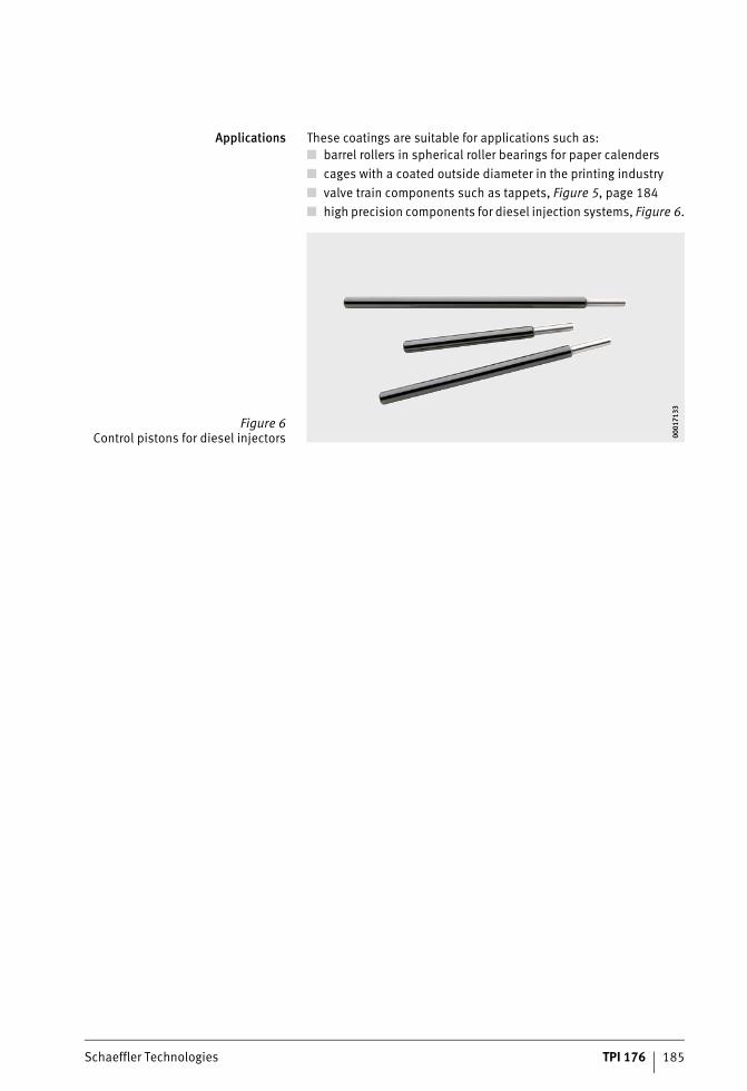
Schaeffler Technologies TPI 176 185
Applications These coatings are suitable for applications such as:■ barrel rollers in spherical roller bearings for paper calenders■ cages with a coated outside diameter in the printing industry■ valve train components such as tappets, Figure 5, page 184■ high precision components for diesel injection systems, Figure 6.
Figure 6Control pistons for diesel injectors 00
0171
3300
0171
33
ST4_3959729163_beschichtungen.fm Seite 185 Donnerstag, 4. April 2013 10:54 10
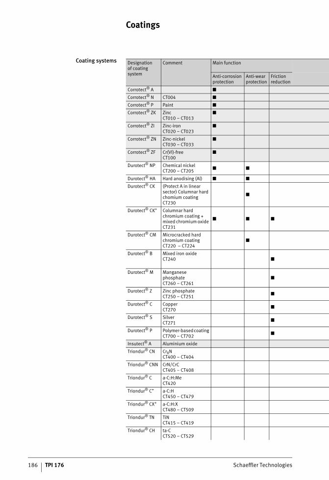
Coatings
186 TPI 176 Schaeffler Technologies
Coating systems Designation of coating system
Comment Main function
Anti-corrosion protection
Anti-wear protection
Friction reduction
Corrotect® A ■
Corrotect® N CT004 ■
Corrotect® P Paint ■
Corrotect® ZK Zinc CT010 – CT013
■
Corrotect® ZI Zinc-iron CT020 – CT023
■
Corrotect® ZN Zinc-nickel CT030 – CT033
■
Corrotect® ZF Cr(VI)-free CT100
■
Durotect® NP Chemical nickel CT200 – CT205 ■ ■
Durotect® HA Hard anodising (Al) ■ ■
Durotect® CK (Protect A in linear sector) Columnar hard chomium coating CT230
■
Durotect® CK+ Columnar hard chromium coating + mixed chromium oxide CT231
■ ■ ■
Durotect® CM Microcracked hard chromium coating CT220 – CT224
■
Durotect® B Mixed iron oxide CT240 ■
Durotect® M Manganese phosphate CT260 – CT261
■
Durotect® Z Zinc phosphate CT250 – CT251 ■
Durotect® C Copper CT270 ■
Durotect® S Silver CT271 ■
Durotect® P Polymer-based coating CT700 – CT702 ■
Insutect® A Aluminium oxide
Triondur® CN CrXN CT400 – CT404
Triondur® CNN CrN/CrCCT405 – CT408
Triondur® C a-C:H:Me CT420
Triondur® C+ a-C:H CT450 – CT479
Triondur® CX+ a-C:H:X CT480 – CT509
Triondur® TN TiN CT415 – CT419
Triondur® CH ta-C CT520 – CT529
ST4_3959729163_beschichtungen.fm Seite 186 Donnerstag, 4. April 2013 10:54 10
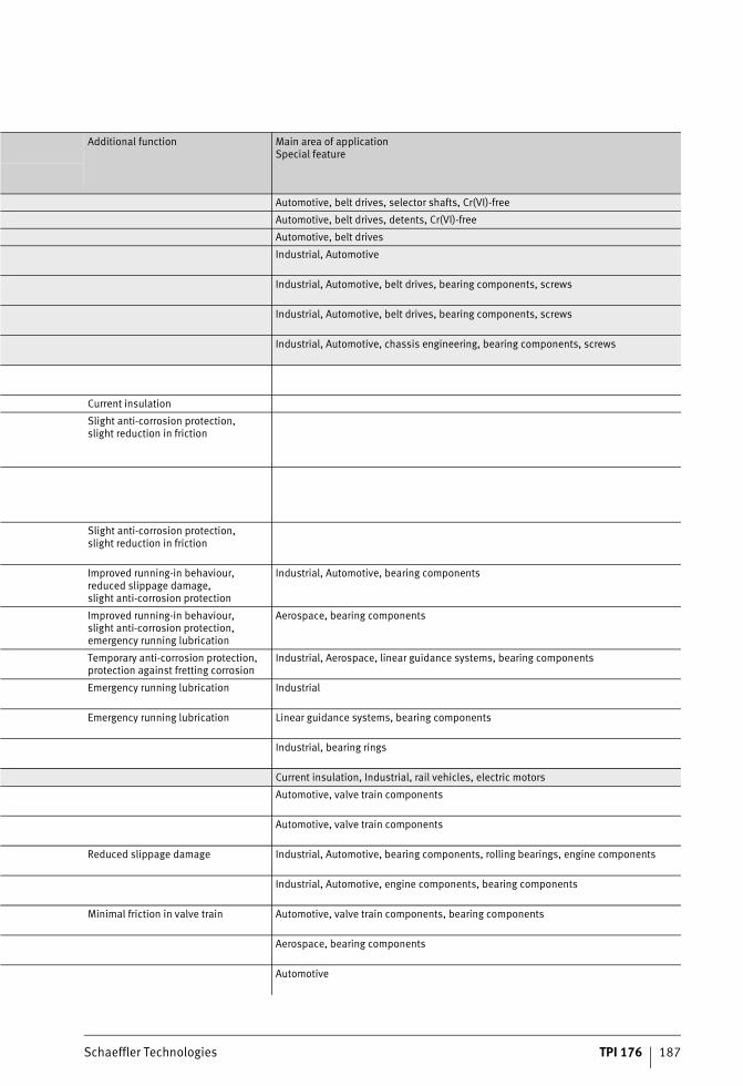
Schaeffler Technologies TPI 176 187
Additional function Main area of application Special feature
Automotive, belt drives, selector shafts, Cr(VI)-free
Automotive, belt drives, detents, Cr(VI)-free
Automotive, belt drives
Industrial, Automotive
Industrial, Automotive, belt drives, bearing components, screws
Industrial, Automotive, belt drives, bearing components, screws
Industrial, Automotive, chassis engineering, bearing components, screws
Current insulation
Slight anti-corrosion protection, slight reduction in friction
Slight anti-corrosion protection, slight reduction in friction
Improved running-in behaviour, reduced slippage damage, slight anti-corrosion protection
Industrial, Automotive, bearing components
Improved running-in behaviour, slight anti-corrosion protection, emergency running lubrication
Aerospace, bearing components
Temporary anti-corrosion protection, protection against fretting corrosion
Industrial, Aerospace, linear guidance systems, bearing components
Emergency running lubrication Industrial
Emergency running lubrication Linear guidance systems, bearing components
Industrial, bearing rings
Current insulation, Industrial, rail vehicles, electric motors
Automotive, valve train components
Automotive, valve train components
Reduced slippage damage Industrial, Automotive, bearing components, rolling bearings, engine components
Industrial, Automotive, engine components, bearing components
Minimal friction in valve train Automotive, valve train components, bearing components
Aerospace, bearing components
Automotive
ST4_3959729163_beschichtungen.fm Seite 187 Donnerstag, 4. April 2013 10:54 10
Industrial Service
#tpi176__en_gb__de.xml_FM8_en_gb.book Seite 188 Donnerstag, 4. April 2013 8:22 08
Schaeffler Technologies TPI 176 189
Page
Industrial Service
Industrial Aftermarket Portfolio ................................................................................. 190
Mountig Toolbox..................................................................... 191
Condition monitoring Grease sensor FAG GreaseCheck ............................................. 192
Oil sensor FAG Wear Debris Check ........................................... 193
Relubrication systems Single-point lubricators .......................................................... 194
Small lubrication systems ....................................................... 194
ST4_9312042891_teil_ivz.fm Seite 189 Donnerstag, 4. April 2013 10:55 10
190 TPI 176 Schaeffler Technologies
Industrial Aftermarket
Portfolio Schaeffler Industrial Aftermarket (IAM) is responsible for replace-ment parts and service business for end customers and sales part-ners in all significant industrial sectors. On the basis of innovative solutions, products and services relating to rolling and plain bearings, the service function of Industrial Aftermarket offersa comprehensive portfolio that covers all phases in the lifecycleof the rolling bearing and takes account of the total costs (TCO), Figure 1.
The portfolio in the area of maintenance and quality assurance extends from mounting, through plant monitoring, to the introduc-tion and implementation of preventive maintenance measures.In more than half of all cases, inadequate lubrication is the cause of unplanned machine downtime. The life of rotating machine elements can be significantly extended by the use of greases appropriate to the different operating and environmental conditions as well as the definition of and adherence to lubrication intervals and quantities.
Figure 1Industrial Aftermarket 00
0192
8700
0192
87
ST4_9221493131_industrial_afte.fm Seite 190 Donnerstag, 4. April 2013 10:55 10
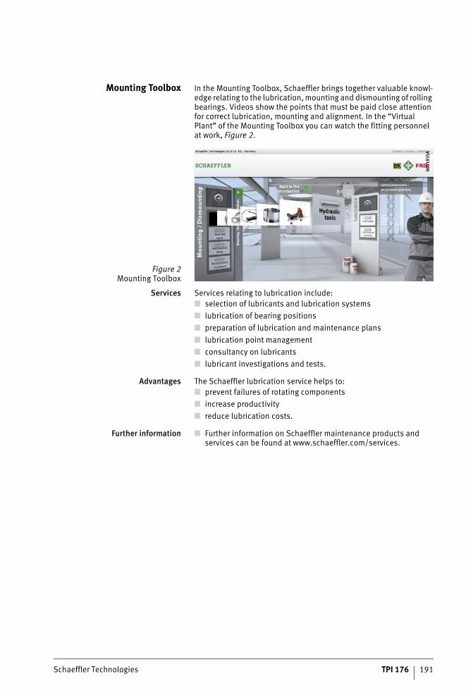
Schaeffler Technologies TPI 176 191
Mounting Toolbox In the Mounting Toolbox, Schaeffler brings together valuable knowl-edge relating to the lubrication, mounting and dismounting of rolling bearings. Videos show the points that must be paid close attention for correct lubrication, mounting and alignment. In the “Virtual Plant” of the Mounting Toolbox you can watch the fitting personnel at work, Figure 2.
Services Services relating to lubrication include:■ selection of lubricants and lubrication systems■ lubrication of bearing positions■ preparation of lubrication and maintenance plans■ lubrication point management■ consultancy on lubricants■ lubricant investigations and tests.
Advantages The Schaeffler lubrication service helps to:■ prevent failures of rotating components■ increase productivity■ reduce lubrication costs.
Further information ■ Further information on Schaeffler maintenance products and services can be found at www.schaeffler.com/services.
Figure 2Mounting Toolbox
0001
935A
0001
935A
ST4_9221493131_industrial_afte.fm Seite 191 Donnerstag, 4. April 2013 10:56 10
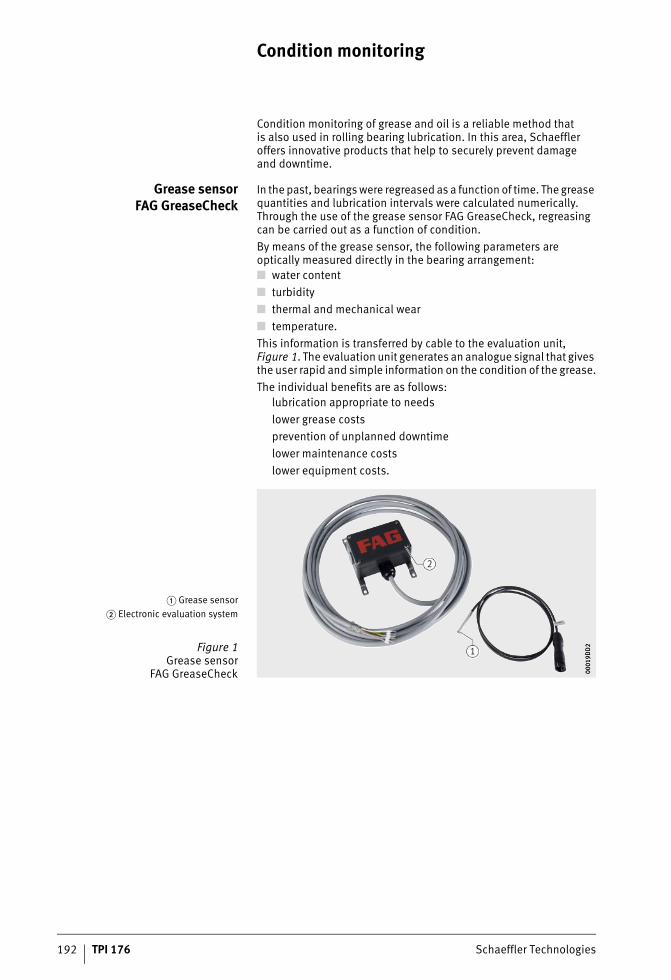
192 TPI 176 Schaeffler Technologies
Condition monitoring
Condition monitoring of grease and oil is a reliable method thatis also used in rolling bearing lubrication. In this area, Schaeffler offers innovative products that help to securely prevent damageand downtime.
Grease sensorFAG GreaseCheck
In the past, bearings were regreased as a function of time. The grease quantities and lubrication intervals were calculated numerically. Through the use of the grease sensor FAG GreaseCheck, regreasing can be carried out as a function of condition.By means of the grease sensor, the following parameters are optically measured directly in the bearing arrangement:■ water content■ turbidity■ thermal and mechanical wear■ temperature.This information is transferred by cable to the evaluation unit, Figure 1. The evaluation unit generates an analogue signal that gives the user rapid and simple information on the condition of the grease.The individual benefits are as follows:
lubrication appropriate to needslower grease costsprevention of unplanned downtimelower maintenance costslower equipment costs.
� Grease sensor� Electronic evaluation system
Figure 1Grease sensor
FAG GreaseCheck 0001
9DD
200
019D
D2
ST4_9543607563_zustandsueberwa.fm Seite 192 Donnerstag, 4. April 2013 10:56 10
Schaeffler Technologies TPI 176 193
Oil sensorFAG Wear Debris Check
FAG Wear Debris Check is an oil sensor that monitors the quantityof wear particles in fluids and classifies these according to size and material. The oil sensor is installed either in an ancillary flow ofthe recirculating lubrication system in the gearbox ahead of the filter or in a separate circuit.Typical applications for the FAG Wear Debris Check can be found,for example, in gearboxes in raw material extraction plant and inthe steel industry, planetary gearboxes in wind turbines or in ship propulsion systems.The features of the oil sensor are as follows:■ monitoring of the number of particles in the oil■ differentiation of the particles into ferrous and non-ferrous
metals■ classification of the particles according to size■ possible integration in an online monitoring system for linking
of oil particle and vibration data.Where oil and vibration monitoring facilities are combined,damage in gearboxes with recirculating oil lubrication can be detected at an early stage and the source can be determined.In this way, it is possible to prevent production shutdowns or secondary damage.
ST4_9543607563_zustandsueberwa.fm Seite 193 Donnerstag, 4. April 2013 10:56 10
194 TPI 176 Schaeffler Technologies
Relubrication systems
Lubricators and lubrication systems automatically provide bearings with the correct quantity of lubricant. This prevents the most frequent cause of rolling bearing failure: inadequate or incorrect lubrication. Approximately 90% of bearings are lubricated with grease. Relubrication with the correct quantity of grease atthe appropriate intervals gives a significant increase in the lifeof bearings.
Single-point lubricators Lubricators convey fresh grease in the defined quantity at the correct time to the contact points of the rolling bearing.The devices adhere to the lubrication and maintenance intervals and prevent undersupply or oversupply of grease. Plant downtime and maintenance costs are reduced as a result.Lubricators have the following advantages:■ individually configured, precise supply to each bearing position■ fully automatic, maintenance-free operation■ reduced personnel costs compared to manual relubrication■ different dispensing times can be selected■ pressure buildup to max. 25 bar.
Small lubrication systems A single-point or multi-point lubrication system can supply lubrication points precisely and irrespective of temperature.The dispensing times can be set variably.
CONCEPT8 This single-point and multi-point lubrication system can grease up to eight lubrication points. The grease cartridges are available inthe size 800 cm3. The lubrication system controls the greasing ofthe lubrication points independently of the machine. The voltage supply for the drive of the lubrication system is provided by a mains power pack.The advantages of the lubrication system are as follows:
suitable for oil and grease up to NLGI 3reliable piston pump as delivery pumpoperating temperature from –20 °C to +70 °Clow operating voltage of 24 VDCpressure buildup to max. 70 bar.
ST4_9543609739_schmierger_te.fm Seite 194 Donnerstag, 4. April 2013 10:56 10

Schaeffler Technologies TPI 176 195
ST4_9543609739_schmierger_te.fm Seite 195 Donnerstag, 4. April 2013 10:56 10
Lubrication lexicon
#tpi176__en_gb__de.xml_FM8_en_gb.book Seite 196 Donnerstag, 4. April 2013 8:22 08
Schaeffler Technologies TPI 176 197
Lubrication lexicon
AAcid number NZ Indicator of the ageing of a mineral oil. It indicates how much mg
potassium hydroxide is required to neutralise the free acids thatare contained in 1 g of oil. In the case of doped oils, the acid number in the fresh condition is normally above zero due to the presence of agents. A change in the acid number compared to the new condition should not exceed a value of 2.
Additive Substance soluble in oil that is added to lubricants in order toimprove their characteristics through chemical or physical effects (for example the EP effect, viscosity/temperature behaviour, solidification point, flowability, oxidation resistance, foaming).
Adhesive oil Highly viscous, tough and sticky lubricant that is normally usedin predissolved form.
Ageing Undesirable chemical changes in mineral and synthetic lubricants that occur during use and storage. They are initiated by reactionwith oxygen (formation of peroxides, hydrocarbon radicals).This oxidation is accelerated by heat, light and the catalytic influences of metals and other contaminants. Acids and sludgeare formed. Anti-ageing products, so-called antioxidants (AO),delay ageing.
Agent See section Additive, page 197.
Aluminiumcomplex soap grease
Grease based on aluminium complex soaps with good water resistance and, through the use of high pressure additives,a high pressure capacity. Depending on the base oil, they can be used at up to approx. +160 °C.
Analysis data Data that describe the physical and chemical characteristicsof lubricants. These include: density, flash point, viscosity, solidification point, dropping point, penetration, acid number and saponification number. Within a certain scope, they allow conclusions to be drawn as to useability.
Antioxidant (AO) Agent that leads to a considerable delay in lubricant ageing.
Anti-wear additive Additive intended to reduce wear in the mixed friction range.A distinction is made between mildly acting additives (such as aliphatic acids, aliphatic oils), high pressure agents (such as sulphur, phosphorus and zinc compounds) and solid lubricants (such as graphite, PTFE, molybdenum disulphide).
Arcanol Selected greases that are sold by Schaeffler Group Industrial.The operating limits of individual greases have been determined using the most modern test methods (for example FE8 and FE9 test rigs) under various operating conditions and with rolling bearingsof various types. They can be used to fulfil almost all requirements placed on the lubrication of bearings, see table, page 128.
ST4_9703971851_schmierungslexi.fm Seite 197 Donnerstag, 4. April 2013 10:57 10
198 TPI 176 Schaeffler Technologies
Lubrication lexicon
Aromatic compound Unsaturated hydrocarbon compound with a ring-shaped molecular structure (for example benzene, toluene, naphthalene).Aromatic compounds have poor viscosity/temperature behaviour and have an unfavourable influence on the oxidation resistanceof lubricants.
Ash content The content of non-combustible residues in a lubricant,normally metal oxides. The ash may have different origins.These include agents dissolved in the oil, graphite, molybdenum sulphide as well as soaps and thickeners in greases. Fresh, undoped mineral oil raffinates must be complete free from ash. Used oil will also contain undissolved metal soaps that are formed in operation, as well as non-combustible residues of contaminants, such as wear debris from bearing parts and seals. The ash contact can occasionally be used to determine approaching bearing damage.
ASTM Abbreviation for American Society for Testing and Materials.An institute whose activities include the formulation of the American mineral oil standards.
ATF Abbreviation for Automatic Transmission Fluid. Special oils thatare matched to the requirements present in automatic gearboxes.
BBarium
complex soap greaseGrease comprising barium complex soaps and mineral oils or synthetic oils. Barium complex soap greases are water-repellent, have high working stability and the lubricant film has high loadcarrying capacity.
Base oil The oil contained in the grease is described as the base oil.The oil proportion varies according to the thickener and intended purpose of the grease. The proportion and viscosity of the base oil change the penetration and friction behaviour of the grease.
Bentonite Inorganic thickener that is used in the production of temperature-resistant greases with good cold characteristics. It is included inthe class of minerals (aluminium silicate).
Bleeding The base oil in the grease becomes separate from the thickener.
Bright stock Highly viscous, refined oil residue derived from vacuum distillation. It is used as a mixing component for oils and improves the lubri-cation behaviour.
ST4_9703971851_schmierungslexi.fm Seite 198 Donnerstag, 4. April 2013 10:57 10
Schaeffler Technologies TPI 176 199
CCalcium soap grease Greases comprising calcium soaps and mineral oils. They have
good water resistance and are therefore frequently used as a sealant grease against water. Since they offer hardly any resistance to corrosion, they must contain agents to give anti-corrosion protection. Due to their limited temperature range of –20 °C to +50 °C, they are not used widely.
Centipoise (cP) Unit commonly used in earlier times for dynamic viscosity: 1 cP = 1 mm2/s.
Centistoke (cSt) Unit commonly used in earlier times for kinematic viscosity: 1 cSt = 1 mm2/s.
Cold behaviour See section Solidification point, page 209 andsection Flow pressure, page 201.
Colour of oils This allows conclusions to be drawn on the operating life.Fresh oil can be more or less dark. As a result, ageing can only be detected by comparing the oil to be examined with a sample ofthe fresh oil. A dark colour may also occur, however, if the oil is contaminated by dust, soot or wear debris. This is possible witheven very small quantities.
Combustion point The lowest temperature, in relation to a defined pressure,at which the vapours from a fluid heated to a uniform extent will, after ignition by a flame, continue to burn for a period of fiveseconds (DIN ISO 2592).
Complex grease Greases based on the metal soaps of high-molecular aliphatic acids. They also contain metal salts derived from low-molecular organic acids. These salts form complexes with the acids that have more favourable characteristics than simple soap greases (temperature limits, behaviour in the presence of water, anti-corrosion protection, pressure absorption capacity).
Consistency See section Penetration, page 206.
Copper strip test Method for the qualitative testing of the corrosion effect of mineral oils (DIN EN ISO 2160) and greases (DIN 51811) on copper.
Co-rotation Transport of the grease by rotating parts. Grease clumps repeatedly enter the space between the rolling element and raceways,leading to an increase in the undesirable worked penetration.At high speeds, a grease must therefore be selected that does not tend to undergo co-rotation. Co-rotation is influenced by the thickener, penetration, temperature and bearing type.
ST4_9703971851_schmierungslexi.fm Seite 199 Donnerstag, 4. April 2013 10:57 10
200 TPI 176 Schaeffler Technologies
Lubrication lexicon
DDecompression behaviour This allows statements on the suitability of greases for use in central
lubrication systems (DIN 51816-2).
Demulsifying ability The separation capacity of oils from oil/water mixtures.
Density Mass per volume of mineral oil products in relation to 20 °C.It has the symbol � and is stated in g/cm3. The density is dependent on the chemical structure of the oil. In oils with the same origin,it increases with increasing viscosity and the increasing degree of refining. Density alone is no measure of quality.
Deposit Lubricant residues such as soot and contaminant particles that occur as a result of ageing of the oil, excessively long oil change intervals and mechanical wear under the strong influence of heat. They settle in the oil sump, in the bearings, in filters and inthe lubricant feeds and can endanger the operational reliability.
Detergent Agent with the ability to separate residues and clean deposits from surfaces to be relubricated.
Dispersant An agent in oil that holds solid contaminants in a very finely distributed suspension until they are filtered out or removed by means of an oil change.
Dispersion A system of finely distributed, non-soluble substances in a liquid or gas, e.g. an emulsion or suspension.
Dispersion greasing A method for introducing lubricant into the rolling bearing.The rolling bearing is immersed in a dispersion bath (dispersant and grease). After vapourisation of the dispersant, a lubricant layer with a thickness of 1 �m to 100 �m remains on the bearing surface.This method reduces the friction but also the grease operating life.
Distillate Hydrocarbon mixture derived from the distillation of crude oil.
DLC Diamond-like carbon coatings are protective carbon layers resembling diamond. They essentially comprise a highly crosslinked amorphous carbon matrix with various proportions of sp2 and sp3 orbital bonds as well as various contents of embedded oxygen.The tribological behaviour of DLC layers is more similar to the behaviour of graphite.
Doped lubricants Oils or greases that contain one or more agents to improve specific characteristics, see section Additive, page 197.
Dropping point Guide value for the upper operating temperature of a grease.The grease is heated under standardised test conditions in accordance with DIN ISO 2176. The temperature is determined at which, when a nipple is opened, the sample flows and falls tothe base of the test pipe.
Dynamic viscosity See section Viscosity, page 211.
ST4_9703971851_schmierungslexi.fm Seite 200 Donnerstag, 4. April 2013 10:57 10
Schaeffler Technologies TPI 176 201
EEmcor method Testing of the anti-corrosion characteristics of rolling bearing
greases in accordance with DIN 51802.
Emulsifiability The tendency of an oil to form an emulsion with water.
Emulsifier Substance that acts on the emulsifiability of oils.
Emulsion A mixture of fluids that are not normally soluble in each other.An emulsifier is generally used when mixing mineral oils with water.
EP additive Oils or greases that contain Extreme Pressure agents in order to prevent wear and fretting.
Ester Compound produced by chemical means between acids and alcohols with the release of water. They can be used to produce synthetic oils, whose characteristics are defined by the molecular structure of the ester. Esters of higher alcohols with bivalent aliphatic acids form so-called diester oils. Ester oils comprising multivalent alcohols and various organic acids have particularlyhigh thermal stability.
FFlash point The lowest temperature at which, under specified test conditions,
so much oil vapour is released that the oil/air mixture ignites forthe first time in the presence of a flame. It is included with the key data for an oil and is standardised in accordance with DIN ISO 2592. The flash point has hardly any significance in relation to the tribological assessment.
Flowable grease Grease of semi-fluid to paste-like consistency ofthe NLGI grades 000, 00 and 0. In order to increase the pressure absorption capacity, they may contain extreme pressure additives (EP) or solid lubricants. They are normally used for gearbox lubrication.
Flow pressure The flow pressure gives information on the consistency of a grease and indicates its flow behaviour. In accordance with DIN 51805,this is the pressure that is required in order to press a stream of grease through a standardised nozzle. In accordance with DIN 51825, it determines the lower operating temperature.
Four ball test machine (VKA) Device for testing of lubricants with high pressure and anti-wear agents, standardised in accordance with DIN 51350.In order to assess the high pressure additives, four balls are arranged in a pyramid. The upper ball rotates and is subjectedto a force until the balls weld together. The welding force measured is the so-called VKA value.In order to assess the anti-wear additives, the same test is performed at a defined test force for one hour. The impression diameter of the three static balls is then measured and used as the wear parameter.
ST4_9703971851_schmierungslexi.fm Seite 201 Donnerstag, 4. April 2013 10:57 10
202 TPI 176 Schaeffler Technologies
Lubrication lexicon
GGearbox grease See section Flowable grease.
Gearbox oil Oil for gearboxes that are used predominantly in the industrial sector. These are standardised in accordance with DIN 51509 and DIN 51517 (oils, type C, CL, CLP). In the automotive sector,gearbox oils are classified in accordance with SAE.
Gel grease Inorganic thickener type, normally silica gel. The thickener comprises very finely distributed solid particles whose surface can absorb oil. Gel greases have a wide operating temperature range and are resistant to water. They are less suitable for high speedsand loads.
Grease Consistent mixture of thickener and base oil. A distinction is made between different type of grease. Metal soap greases comprise metal soaps as thickeners and oils. Soap-free greases bind the oil using inorganic gel formers or organic thickeners. Synthetic greases comprise organic or inorganic thickeners and synthetic oils. For the selection of greases, see table Greases, page 84.
Grease operating life The period between startup and failure of a bearing as a result of lubricant failure, see section Grease operating life, page 95. The grease operating life is dependent on the grease quantity, grease type (thickener, base oil, additives), bearing type, bearing size, mag-nitude and type of load, speed parameters and bearing temperature. It can be estimated if the operating conditions are known.The grease operating life is also described as a lubrication interval. It must not be confused with the relubrication interval,see section Relubrication interval, page 207.
HHard layer A particularly hard, oxidation-resistant and chemically resistant
layer. It comprises an oxide, nitride, carbide, carbonitride or carboxynitride of an element of the main group 4, 5 or 6 ofthe periodic table, such as TiN, CrN.
HD oil Heavy duty oils are engine oils that are matched to the considerable requirements in internal combustion engines by means of additives.
High pressure additive See section EP additive, page 201.
Homogenisation The final phase of grease production. In order to achieve a uniform structure and very fine distribution of the thickener, the greaseis subjected to strong shearing. This is carried out in a special machine, the so-called homogeniser.
Hydraulic fluid Pressure fluid for force transmission and control in hydraulic plant.It is standardised in accordance with DIN 51524 and comprises mineral oil with a low solidification point. It is resistant to ageing, thin, non-foaming and fire-resistant.
Hydraulic oil See section Hydraulic fluid.
Hypoid oil High pressure oil with EP additives for hypoid gearboxes that are mainly used for final drives in motor vehicles.
ST4_9703971851_schmierungslexi.fm Seite 202 Donnerstag, 4. April 2013 10:57 10
Schaeffler Technologies TPI 176 203
IInhibitor Agent that delays certain reactions in a lubricant.
Inhibitors are used in preference to combat ageing and corrosion processes in lubricants.
ISO VG See section Viscosity classification, page 211.
KKey data See section Analysis data, page 197.
Kinematic viscosity See section Viscosity, page 211.
LLithium soap grease Greases based on lithium soap. They are characterised by good
water resistance and a wide operating temperature range.They contain oxidation and corrosion inhibitors as well as extreme pressure additives (EP). Due to their good characteristics, lithium soap greases are used widely for the lubrication of rolling bearings. The operating limits of normal lithium soap greases are at –35 °C and +130 °C.
Lubricant additive See section Additive, page 197.
Lubrication interval See section Grease operating life, page 202.
ST4_9703971851_schmierungslexi.fm Seite 203 Donnerstag, 4. April 2013 10:57 10
204 TPI 176 Schaeffler Technologies
Lubrication lexicon
MMechanical-dynamic
lubricant testingTest methods for the investigation of rolling bearings under conditions close to operation (operating conditions and environ-mental conditions). The lubricant is assessed by observing the behaviour of the test element and lubricant during testing and their condition after testing. The results of model test devices can only be applied to rolling bearings under certain conditions. Mehods are therefore used in preference that include rolling bearings as test elements.
MIL-Spezifikation Minimum requirement of US armed forces for operating materials to be supplied. Although these are aimed only at the military sector, these specifications have also found use in the civil sector.Engine and machine manufacturers have in some cases the same minimum requirements for lubricants. There are valid as a quality indicator.
Mineral oil Oil derived from crude oil that is processed by distillation and refining for lubrication purposes. In chemical terms, it predomi-nantly comprises hydrocarbons.
Miscibility of oils Statement as to whether different oils are miscible with each other. This is not always possible with different grades and manufacturers. The exception is HD engine oils, which can be mixed with each other in almost all cases. If fresh oils are mixed with used oils, thereis a risk that sludge will be precipitated. In order to exclude this possibility, it is recommended that samples should be mixed ina glass beaker in advance.
Multigrade oil Engine oils and gearbox oils with an improved viscosity/temperature behaviour. In comparison with single grade oils, the multigrade oilis not too thick and low temperatures and not too thin at high temperatures.
NNLGI Abbrevation for the National Lubricating Grease Institute
in the USA. Greases are subdivided into grades defined by the NLGI, see section Penetration, page 206.
Nominal viscosity See section Viscosity, page 211.
Normal oil Oil of the class L-AN in accordance with DIN 51501,which is used if no particular requirements are present.
ST4_9703971851_schmierungslexi.fm Seite 204 Donnerstag, 4. April 2013 10:57 10
Schaeffler Technologies TPI 176 205
OOil separation The tendency of a grease to release oil in the case of extended
storage or at increased temperature. Long term lubrication requires the long term release of a small quantity of oil that must, however, be large enough to ensure supply to all contact surfaces.The oil separation is defined in accordance with DIN 51817.
Oil, type B Dark mineral oils containing bitumen with good adhesion capacity, in accordance with DIN 51513.
Oil, type C, CL, CLP Gearbox oils for recirculating lubrication,in accordance with DIN 51517.
Oil, type CG Slideway oils.
Oil, type K Refrigerator oils in accordance with DIN 51503.
Oil, type N Normal oils in accordance with DIN 51501.
Oil, type T Steam turbine and regulator oils in accordance with DIN 51515-1.
Oil, type V Air compressor oils in accordance with DIN 51506.
Oil, type Z Steam cylinder oils in accordance with DIN 51510.
Operating viscosity Kinematic viscosity (see section Viscosity, page 211) of an oil at operating temperature. It has the symbol �. The operating viscosity can be determined with the aid of a viscosity/temperature diagram. For mineral oils with an average viscosity/temperature behaviour, Figure 2, page 24.
Oxidation See section Ageing, page 197.
ST4_9703971851_schmierungslexi.fm Seite 205 Donnerstag, 4. April 2013 10:57 10
206 TPI 176 Schaeffler Technologies
Lubrication lexicon
PPassivation The formation of a covering layer that prevents or considerably slows
down the corrosion of the metallic base material.Electroplating methods are used such as thick layer passivation, yellow and black chromate passivation.
Penetration Indicator of the deformability of a grease.It is determined by dropping a standardised brass cone froma defined height into a container filled with grease. The penetration depth after a period of 5 s is then measured. The measured valueis stated in 0,1 mm.The National Lubricating Grease Institute has subdivided the measurement values into penetration grades (NLGI grades) 000 to 6, see table NLGI grade, page 66. Greases for rolling bearings are normally in the consistency grades 1 to 3. This subdivision is used worldwide and is standardised in accordance with DIN 51818.The consistency of greases changes as a result of mechanical load.A distinction is made between static penetration and worked penetration.
Pour point See section Solidification point, page 209.
Pressure/viscosity behaviour The influence of pressure on the viscosity of an oil. With increasing pressure, the vicosity of mineral oils increases, Figure 4, page 11.
ST4_9703971851_schmierungslexi.fm Seite 206 Donnerstag, 4. April 2013 10:58 10
Schaeffler Technologies TPI 176 207
RRadiation Influence on the operating life of lubricants, for example as a result
of radioactive substances. The energy dose is stated in Gray (Gy) (1 Gy = 1 J/kg). The equivalent dose is stated in Sievert (Sv) (1 Sv = 1 J/kg). In addition to the SI units, the older units Rad (rd) and Rem (rem) are still commonly used in some cases (1 rd = 1 rem). Conversion: 1 Gy = 100 rd and 1 Sv = 100 rem.
Radioactivity See section Radiation, page 207.
Raffinate Product occurring as a result of refining.
Recirculating lubrication Lubrication method in which the oil is repeatedly fed to the friction point and becomes effective.
Reference viscosity Kinematic viscosity (see section Viscosity, page 211) of an oil,as allocated to a defined lubrication condition. It has the symbol �1. The reference viscosity can be determined with the aid of the mean bearing diameter and the speed, Figure 2, page 24.The so-called viscosity ratio � of the operating viscosity � tothe reference viscosity �1 allows an assessment of the lubrication condition (� = ���1).
Refining Method for the purification of distillates in the production of oils. Refining improves the ageing resistance of oils.Unstable compounds in which nitrogen, oxygen or metal salts may be embedded are separated out. The most important refining methods include sulphuric acid refining (sulphuric acid raffinate) and solvent refining (solvent raffinate).
Refrigerator oil Oil that is subjected in refrigerators to the effect of the refrigerant. These are subdivided into groups in accordance with the refriger-ants. Their minimum requirements are standardised in DIN 51524.
Relubrication interval The period during which a bearing is relubricated. The relubrication interval should be defined as shorter than the grease operating life.
ST4_9703971851_schmierungslexi.fm Seite 207 Donnerstag, 4. April 2013 10:58 10
208 TPI 176 Schaeffler Technologies
Lubrication lexicon
SSAE Abbreviation for Society of Automotive Engineers. Various standards
and classifications, in particular the SAE classification for engineoils are derived from this association of US American automotive engineers and are used worldwide, see section SAE classification.
SAE classification Viscosity classes for engine oils in accordance with SAE, used inthe vehicle sector. A comparison of viscosities from SAE and ISO VG is possible, Figure 6, page 79.
Saponification number (VZ) Indicator of the ligated and free acids in one gram of grease.It indicates how many milligrams of the acid regulator potassium hydroxide are required in order to neutralise the free and ligated acids in one gram of oil and saponify the esters present.The saponification number indicates the change in the oil in unused and used mineral oils with and without additives.
Seal behaviour Organic seal materials show behaviour that differs from oils and greases. In some cases, seals undergo swelling, shrinking or embrittlement or even dissolve. The operating temperature and composition of the lubricant as well as the effective duration havea major influence. Information on the resistance of seals is provided by their manufacturers and, as appropriate, by the lubricant manufacturers.
Silicone oil Synthetic oils used under special operating conditions.They have more favourable key data than mineral oils but inferior lubrication characteristics and a lower pressure absorption capacity, see table Base oils and their typical characteristics, page 77.
Sludge formation Precipations of mineral oil products that are deposited as sludge. These are oxidation products and polymerisates that are formed through the influence of air and water.
Sodium soap grease No longer commonly used.
Solid foreign matter Non-soluble, foreign contaminants in n-heptance or in solvent mixtures in accordance with DIN 51813. Solid foreign matter in oils are determined in accordance with DIN 51592 E and, in greases and solvent mixtures, in accordance with DIN 51813.
Solid lubricant Substances suspended or directly added in oils and greases that reduce friction. The most well known of these are graphite, PTFE and molybdenum disulphide.
ST4_9703971851_schmierungslexi.fm Seite 208 Donnerstag, 4. April 2013 10:58 10
Schaeffler Technologies TPI 176 209
Solidification point The lowest temperature of a mineral oil at which a sample still flows when cooled under certain conditions.
Solvate Mineral oils refined using solvent. Also known as solvent raffinate.
Specification Military and company specifications for lubricants, that definethe physical and chemical characteristics and test methods.
Spindle oil Thin oils with a viscosity of approx. 10 mm2/s to 68 mm2/s at +40 °C.
Static penetration Penetration measured at +25 °C of a grease sample that was not pretreated in the grease shaper.
Steam turbine oil Highly refined, ageing resistant oils used for the lubricaion of gearboxes and bearings in steam turbines. The oils are availablein both doped (EP) and undoped form. They are designated in accordance with DIN 51515-1 as oil, type T.
Stick/slip additive Agent added to lubricants to prevent jolting sliding motion,for example on the guideways of machine tools.
Suspension Solid bodies finely distributed in fluids, for example non-soluble agents in oils.
Swelling behaviour The influence, for example on the form and structure of rubber and elastomers due to the effect of lubricants (DIN 53521).
Synthetic oil Synthetic oils are produced by chemical synthesis of molecules. Polymerisation leads to polyalphaolefins (PAO) or polyalkylene glycols (PAG) or condensation reactions lead to esters. Synthetic oils have advantages in comparison with mineral oils at particularly low or particularly high operating temperatures. They are, however, significantly more expensive.
ST4_9703971851_schmierungslexi.fm Seite 209 Donnerstag, 4. April 2013 10:58 10
210 TPI 176 Schaeffler Technologies
Lubrication lexicon
TThickener The component of greases that retains the base oil in the grease.
The most frequent thickeners are metal soaps (such as Li-, Ca-,Na- 12-hydroxy stearate) or compounds of the type polycarbamide, PTFE and Mg-Al layered silicate (bentonite).
Thixotropy The characteristic of a lubricant in becoming temporarily softer/thinner under mechanical effects such as stirring or kneading. Greases behave in a thixotropic manner when their viscosity decreases as a result of mechanical strain and increases again when at rest. Preservative oils, especially those with additives,also behave thixotropically.
Toughness See section Viscosity, page 211.
ST4_9703971851_schmierungslexi.fm Seite 210 Donnerstag, 4. April 2013 10:58 10
Schaeffler Technologies TPI 176 211
VVapourisation loss The loss in mass of an oil at higher temperatures through
vapourisation. It may be equivalent to increased oil consumption and can change the characteristics of the oil.
Viscosity A fundamental physical characteristic of oils. It indicates the inner friction of a fluid. In a physical sense, it is the resistance opposing the reciprocal displacement of the adjacent layers of a fluid.A distinction is made between the dynamic viscosity � andthe kinematic viscosity �. The kinematic viscosity is the dynamic viscosity relative to the density �. The relationship � = � � � applies.For dynamic viscosity, the SI units Pa � s and mPa � s are used.These replace the units Poise P and Centipoise cP that were commonly used in earlier times. Conversion: 1 cP = 10-3 Pa � s.For kinematic viscosity, the SI units m2/s and mm2/s are used. These replace the unit Centistoke cSt that was commonly used in earlier times.The viscosity decreases with increasing temperature and increases with decreasing temperature, see section Viscosity/temperature behaviour (V/T behaviour), page 211. For each viscosity value,the reference temperature must therefore be stated. The nominal viscosity is the kinematic viscosity at +40 °C, see section Viscosity classification, page 211.
Viscosity/temperaturebehaviour (V/T behaviour)
The change in viscosity with temperature. A favourable V/T behaviour is defined as one where the viscosity of an oil does not change considerably with temperature. See also section Viscosity index VI.
Viscosity classification Subdivision of fluid industrial lubricants according to their viscosity (ISO 3448 and DIN 51519). There are 20 viscosity grades defined(in the range from 2 mm2/s to 3 200 mm2/s at +40 °C),see table Viscosity grades ISO VG, page 80.
Viscosity index improver Additives that are dissolved in the oil and improve the viscosity/temperature behaviour. At high temperatures they inducehigher viscosity, while at low temperatures they improve the flow behaviour.
Viscosity index VI Indicator of the viscosity/temperature behaviour of an oil.See also section Viscosity/temperature behaviour (V/T behaviour).
Viscosity ratio See section Reference viscosity, page 207.
ST4_9703971851_schmierungslexi.fm Seite 211 Donnerstag, 4. April 2013 10:58 10
212 TPI 176 Schaeffler Technologies
Lubrication lexicon
WWater content The quantity of water contained in an oil.
Water reduces the lubrication capability, since the lubricant filmis interrupted by water drops. It accelerates ageing and leads to corrosion.The water content is determined by means of distillation or a settling test. In the settling test, water settles on the base of the test tube due to its higher specific gravity. Emulsions must first be heated.In order to confirm a lower water content, the crackle test is used.The oil in the test tube is heated over a flame. If traces of water are present, a crackling noise will be heard. Further information onthe influence of water on lubricants, see section Liquid contami-nants, page 143.
Water resistance The ability of a grease not to change its characteristics underthe influence of water. This is determined by means of a static test in accordance with DIN 51807. It is tested whether and to what extent static, distilled water has an effect on a grease not subjected to load at various temperatures. The result only represents a description of characteristics and does not permit any conclusions as to the water resistance of the grease in practice.
Water separation capacity The ability of an oil to separate from water. Testing is carried out in accordance with DIN 51589.
Worked penetration Penetration measured at +25 °C of a grease sample that was preworked in the grease shaper (DIN 51804-2 and DIN ISO 2137).
ST4_9703971851_schmierungslexi.fm Seite 212 Donnerstag, 4. April 2013 10:58 10

Notes
Schaeffler Technologies TPI 176 213
ST4_9312037387_anhang.fm Seite 213 Donnerstag, 4. April 2013 10:58 10

214 TPI 176 Schaeffler Technologies
Notes
ST4_9312037387_anhang.fm Seite 214 Donnerstag, 4. April 2013 10:58 10

Schaeffler Technologies TPI 176 215
ST4_9312037387_anhang.fm Seite 215 Donnerstag, 4. April 2013 10:58 10

216 TPI 176 Schaeffler Technologies
Notes
ST4_9312037387_anhang.fm Seite 216 Donnerstag, 4. April 2013 10:58 10

Schaeffler Technologies TPI 176 217
ST4_9312037387_anhang.fm Seite 217 Donnerstag, 4. April 2013 10:58 10

218 TPI 176 Schaeffler Technologies
Notes
ST4_9312037387_anhang.fm Seite 218 Donnerstag, 4. April 2013 10:58 10

Schaeffler Technologies TPI 176 219
ST4_9312037387_anhang.fm Seite 219 Donnerstag, 4. April 2013 10:58 10

220 TPI 176 Schaeffler Technologies
Notes
ST4_9312037387_anhang.fm Seite 220 Donnerstag, 4. April 2013 10:58 10

Schaeffler Technologies TPI 176 221
ST4_9312037387_anhang.fm Seite 221 Donnerstag, 4. April 2013 10:58 10

222 TPI 176 Schaeffler Technologies
Notes
ST4_9312037387_anhang.fm Seite 222 Donnerstag, 4. April 2013 10:58 10

Schaeffler Technologies TPI 176 223
ST4_9312037387_anhang.fm Seite 223 Donnerstag, 4. April 2013 10:58 10

224 TPI 176 Schaeffler Technologies
Notes
ST4_9312037387_anhang.fm Seite 224 Donnerstag, 4. April 2013 10:58 10

MAT
NR
0368
6450
1-00
00 /
TPI 1
76 /
GB-
D /
2013
031
/ Prin
ted
in G
erm
any
by b
resl
er
Every care has been taken to ensure the
correctness of the information contained
in this publication but no liability can be
accepted for any errors or omissions.
We reserve the right to make technical
changes.
© Schaeffler Technologies AG & Co. KG
Issued: 2013, March
This publication or parts thereof may not
be reproduced without our permission.
TPI 176 GB-D
Schaeffler Technologies AG & Co. KG
Industriestraße 1 – 3 91074 Herzogenaurach Germany Internet www.ina.com E-mail [email protected]
In Germany: Phone 0180 5003872 Fax 0180 5003873
From other countries: Phone +49 9132 82-0 Fax +49 9132 82-4950
Schaeffler Technologies AG & Co. KG
Georg-Schäfer-Straße 30 97421 Schweinfurt Germany Internet www.fag.com E-mail [email protected]
In Germany: Phone 0180 5003872 Fax 0180 5003873
From other countries: Phone +49 9721 91-0 Fax +49 9721 91-3435
Recommended