M10
7A1
M107A1OPERATOR’S MANUAL

TABLE OF CONTENTS MANUFACTURER’S DISCLAIMER
USE OF THIS MANUAL
SAFETY GUIDELINES
WARRANTY AND SERVICE
DESCRIPTION OF THE FIREARM
BREAK-IN PROCEDURE
SPECIFICATIONS
MAJOR COMPONENTS
SAFETY MECHANISM
BIPOD OPERATION
SIGHTS
ASSEMBLY OF MAJOR COMPONENTS
LOADING AND FIRING
UNLOADING AND CLEARING RIFLE
UNLOADING THE MAGAZINE
REMOVING THE MAINSPRING AND BUFFER
INSTALLING THE MAINSPRING AND BUFFER
CLEANING AND LUBRICATION
GENERAL MAINTENANCE
INSPECTION OF MAJOR COMPONENTS
TROUBLESHOOTING
EXPLODED VIEW AND PARTS LIST
2
2
3
5
6
7
7
8
8
9
9
11
15
18
19
20
21
23
24
25
29
32

M107A1
2
USE OF THIS MANUAL Read this manual before you use or manipulate your Barrett product. It is important that you understand the principles of safe firearm handling in general and the features of this product. This manual is not a substitute for training from a qualified instructor. Important safety topics are discussed in this chapter and throughout this manual. This manual should remain with the product and it should be transferred with the product to subsequent owners. Additional manuals can be ordered from Barrett Firearms Manufacturing or can be downloaded from the company website, barrett.net. Technical specifications are subject to change without notice. Please ensure you have the most updated revision of this manual by checking barrett.net. The revision letter can be found on the back of this manual.
MANUFACTURER’S DISCLAIMERBFMI will not be responsible for injury, death, or damage to property resulting from either intentional or accidental discharge of this firearm or from its function when used for purposes or subjected to treatment for which it was not designed. BFMI will not honor claims involving this firearm which result from careless or improper handling, unauthorized adjustment or parts replacement, corrosion, neglect, the use of the wrong caliber ammunition, or the use of other than commercially manufactured ammunition in good condition, or any combination thereof.
barrett.net
3
SAFETY GUIDELINES
FAILURE TO FOLLOW SAFETY GUIDELINES MAY CAUSE INJURY OR DEATH
AMMUNITIONDo not use hand loaded, re-manufactured, or surplus ammunition. Always use new, clean, dry, properly stored, and correct caliber ammunition from reputable manufacturers.
SAFETY DISTANCEBullets fired from this rifle may travel as far as 4 miles. Make certain that you have an adequate backstop.
HEARING PROTECTIONAlways wear adequate hearing protection when the rifle is firing; wear both earplugs and shooting muffs together for maximum protection. This includes observers. Observers should always be behind the shooter.
EYE PROTECTIONAppropriate eye protection should be worn when both shooting and maintaining your rifle. It is normal for firing to generate airborne dust and debris. Protect your eyes from solvents and uncaptured parts under spring pressure while performing maintenance on your rifle.
MUZZLE CONTROLAlways keep the muzzle pointed in a safe direction. Never allow your muzzle to point at anything that you do not intend to shoot. Upon firing the muzzle brake releases high-pressure gas from its side ports that can damage objects or cause injuries, keep everything away from the vicinity of the muzzle brake.
ASSUME EVERY FIREARM IS LOADED Always treat every firearm as if it were loaded. Look and feel for an empty chamber. Do not trust the extractor to provide an empty chamber.
WARNING

M107A1
4
BEWARE OF BARREL OBSTRUCTIONSEnsure the barrel’s bore is free of obstructions before you fire your rifle. Even the smallest obstruction such as a stuck patch or even grease will cause increased pressures that can rupture the barrel.
KEEP YOUR FINGER OFF THE TRIGGERKeep your finger off the trigger and out of the trigger guard until your sights are aligned on your target and you intend to fire.
KEEP YOUR SAFETY ONKeep your safety on until your sights are aligned on your target and you intend to fire.
FAILURE TO FIREIf your rifle fails to fire when you pull the trigger, do not pull the charging handle. Keep the rifle pointed toward a safe area and wait 2 minutes. If a hang-fire (slow ignition) has occurred, the round will probably fire within two minutes. If the round does not fire, remove and inspect the cartridge. If the primer is indented properly, discard it in a safe manner.
MAINTAIN YOUR RIFLE PROPERLYPerforming proper maintenance, as outlined in this manual, insures that your rifle will be safe to shoot and will perform to design specification for many years. Alterations, modifications or adjustments may damage your rifle, make it unsafe to fire, and will void warranty claims.
STORE YOUR RIFLE SAFELYIt is your responsibility to take reasonable precaution to secure your rifle, keep it properly secured and prevent unauthorized use.
ALCOHOL, MEDICATIONS AND DRUGSDo not handle or operate your rifle under the influence of alcohol, medication, or drugs.

barrett.net
5
WARRANTY AND SERVICEFor one year from date of purchase, Barrett Firearms Manufacturing Inc. (BFMI), warrants to the original owner, that this product was manufactured free of defects in materials and workmanship. BFMI will correct any defect covered under the warranty by repair or replacement with the same or comparable model. BFMI will not be responsible for injury, death, or damage to property resulting from either intentional or accidental discharge of this firearm or from its function when used for purposes or subjected to treatment for which it was not designed. BFMI will not honor claims involving this product which result from careless or improper handling, unauthorized adjustment or parts replacement, corrosion, neglect, the use of the wrong caliber ammunition, or the use of other than commercially manufactured ammunition in good condition, or any combination thereof. Please visit barrett.net for any additional information.
If you need factory service, whether covered under warranty or not, please contact BFMI for instructions on how to have your rifle repaired.
Barrett Firearms Manufacturing Inc.P.O. Box 1077
Murfreesboro, TN 37133-1077615-896-2938
M107A1
6
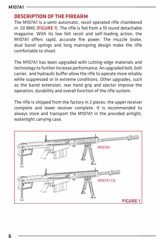
DESCRIPTION OF THE FIREARMThe M107A1 is a semi-automatic, recoil operated rifle chambered in .50 BMG (FIGURE 1). The rifle is fed from a 10 round detachable magazine. With its low felt recoil and self-loading action, the M107A1 offers rapid, accurate fire power. The muzzle brake, dual barrel springs and long mainspring design make the rifle comfortable to shoot.
The M107A1 has been upgraded with cutting-edge materials and technology to further increase performance. An upgraded bolt, bolt carrier, and hydraulic buffer allow the rifle to operate more reliably while suppressed or in extreme conditions. Other upgrades, such as the barrel extension, rear hand grip and ejector improve the operation, durability and overall function of the rifle system.
The rifle is shipped from the factory in 2 pieces: the upper receiver complete and lower receiver complete. It is recommended to always store and transport the M107A1 in the provided airtight, watertight carrying case.
M107A1
M107A1 CQ
FIGURE 1

barrett.net
7
BREAK–IN PROCEDURE Barrett does not offer a specific procedure for barrel break-in other than checking for obstructions and using your new rifle.
Experience has shown that the bore becomes less prone to fouling over time and that accuracy may improve with use. Ensure that the rifle is adequately lubricated and follow the loading/unloading and safety procedures when operating your rifle.
SPECIFICATIONSMODEL M107A1 M107A1 CQCaliber .50 BMG (12.7 x 99 mm) .50 BMG (12.7 x 99 mm)Operation Semi-Automatic Semi-AutomaticWeight 27.55 lbs (12.5 kg) 26.26 lbs (11.91 kg)Overall Length (Assembled) 56.8” (1442.8 mm) 48.4” (1229.4 mm)Length(Takedown Mode)
37.75“ (958.9 mm) Lower 41.38” (1050.9 mm) Upper
37.75“ (958.9 mm) Lower 41.38” (1050.9 mm) Upper
Barrel Length 29” (736.6 mm) 20.6” (523.2 mm)Barrel Twist 1:15 1:15Magazine Capacity 10 rounds 10 roundsStock Integral with lower
receiver - steelIntegral with lower receiver - steel
Safety Manual thumb-lever Manual thumb-leverSights Fixed front, Adjustable
rear sightsFixed front, Adjustable rear sights
Muzzle Velocity (Standard 660 grains (42.8 g) Projectile) 2750 f/s (853 m/s) 2500 f/s (762 m/s)

M107A1
8
MAJOR COMPONENTS - FIGURE 21. Upper receiver2. Bolt carrier group3. Lower receiver4. Magazine
SAFETY MECHANISMThe safety mechanism is located above the grip on the left side of the lower receiver. To place the rifle in the safe mode, push the safety lever selector to the “Safe” position. To place it in the fire mode, push the safety lever to the “Fire” position. (FIGURE 3)
FIGURE 3
FIGURE 2
3
2
1
4
barrett.net
9
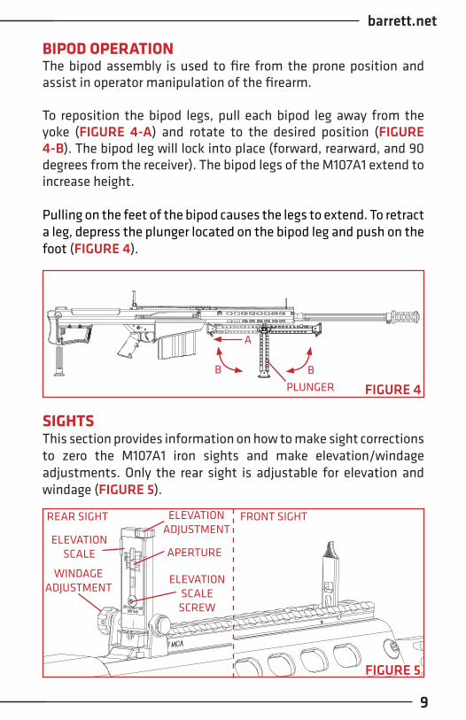
BIPOD OPERATIONThe bipod assembly is used to fire from the prone position and assist in operator manipulation of the firearm.
To reposition the bipod legs, pull each bipod leg away from the yoke (FIGURE 4-A) and rotate to the desired position (FIGURE 4-B). The bipod leg will lock into place (forward, rearward, and 90 degrees from the receiver). The bipod legs of the M107A1 extend to increase height.
Pulling on the feet of the bipod causes the legs to extend. To retract a leg, depress the plunger located on the bipod leg and push on the foot (FIGURE 4).
SIGHTSThis section provides information on how to make sight corrections to zero the M107A1 iron sights and make elevation/windage adjustments. Only the rear sight is adjustable for elevation and windage (FIGURE 5).
FIGURE 5
REAR SIGHT FRONT SIGHTELEVATION ADJUSTMENT
WINDAGE ADJUSTMENT
ELEVATIONSCALE
ELEVATIONSCALESCREW
APERTURE
B B
A
FIGURE 4PLUNGER
M107A1
10
ZEROING PROCEDUREUsing a bore collimator or laser bore sight, project to a 100 meter distance. Rotate the elevation adjustment knob on the rear sight to vertically adjust the aperture to be aligned with the collimator/laser. Loosen the elevation scale screw (FIGURE 5) and adjust the scale to align the 100 meter mark with the aperture . Tighten the elevation scale screw then fire a test group to confirm zero. If needed, make small additional adjustments to the elevation knob until zeroed at 100 meters.
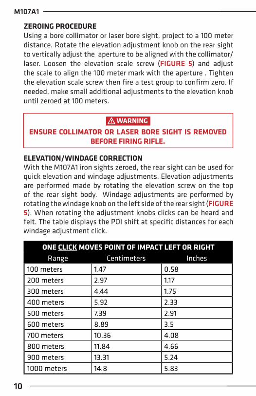
ELEVATION/WINDAGE CORRECTIONWith the M107A1 iron sights zeroed, the rear sight can be used for quick elevation and windage adjustments. Elevation adjustments are performed made by rotating the elevation screw on the top of the rear sight body. Windage adjustments are performed by rotating the windage knob on the left side of the rear sight (FIGURE 5). When rotating the adjustment knobs clicks can be heard and felt. The table displays the POI shift at specific distances for each windage adjustment click.
ENSURE COLLIMATOR OR LASER BORE SIGHT IS REMOVED BEFORE FIRING RIFLE.
WARNING
ONE CLICK MOVES POINT OF IMPACT LEFT OR RIGHTRange Centimeters Inches
100 meters 1.47 0.58200 meters 2.97 1.17300 meters 4.44 1.75400 meters 5.92 2.33500 meters 7.39 2.91600 meters 8.89 3.5700 meters 10.36 4.08800 meters 11.84 4.66900 meters 13.31 5.241000 meters 14.8 5.83
barrett.net
11
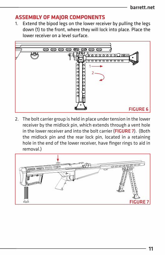
ASSEMBLY OF MAJOR COMPONENTS1. Extend the bipod legs on the lower receiver by pulling the legs
down (1) to the front, where they will lock into place. Place the lower receiver on a level surface.
2. The bolt carrier group is held in place under tension in the lower receiver by the midlock pin, which extends through a vent hole in the lower receiver and into the bolt carrier (FIGURE 7). (Both the midlock pin and the rear lock pin, located in a retaining hole in the end of the lower receiver, have finger rings to aid in removal.)
FIGURE 7
1
2
FIGURE 6
M107A1
12
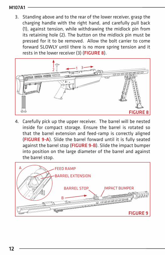
3. Standing above and to the rear of the lower receiver, grasp the charging handle with the right hand, and carefully pull back (1), against tension, while withdrawing the midlock pin from its retaining hole (2). The button on the midlock pin must be pressed for it to be removed. Allow the bolt carrier to come forward SLOWLY until there is no more spring tension and it rests in the lower receiver (3) (FIGURE 8).
FIGURE 8
12 3
4. Carefully pick up the upper receiver. The barrel will be nested inside for compact storage. Ensure the barrel is rotated so that the barrel extension and feed-ramp is correctly aligned (FIGURE 9-A). Slide the barrel forward until it is fully seated against the barrel stop (FIGURE 9-B). Slide the impact bumper into position on the large diameter of the barrel and against the barrel stop.
BARREL STOP IMPACT BUMPER
FIGURE 9
A
B
FEED RAMP
BARREL EXTENSION
barrett.net
13
THE TENSION ON THE BARREL SPRINGS IS APPROXIMATIVELY 70 lbs (32 kg). SERIOUS INJURY COULD RESULT IF SPRINGS
ARE SUDDENLY RELEASED
WARNING
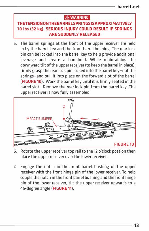
5. The barrel springs at the front of the upper receiver are held in by the barrel key and the front barrel bushing. The rear lock pin can be locked into the barrel key to help provide additional leverage and create a handhold. While maintaining the downward tilt of the upper receiver (to keep the barrel in place), firmly grasp the rear lock pin locked into the barrel key—not the springs—and pull it into place on the forward slot of the barrel (FIGURE 10). Work the barrel key until it is firmly seated in the barrel slot. Remove the rear lock pin from the barrel key. The upper receiver is now fully assembled.
1
2
FIGURE 106. Rotate the upper receiver top rail to the 12 o’clock postion then
place the upper receiver over the lower receiver.
7. Engage the notch in the front barrel bushing of the upper receiver with the front hinge pin of the lower receiver. To help couple the notch in the front barrel bushing and the front hinge pin of the lower receiver, tilt the upper receiver upwards to a 45-degree angle (FIGURE 11).
IMPACT BUMPER

M107A1
14
FIGURE 12
9. Close the upper receiver onto the lower receiver. With the bolt retracted, the upper receiver should fit into the lower receiver easily without being forced. If the upper does not fit on the lower, check front barrel bushing/hinge pin alignment. Release the charging handle SLOWLY until the bolt is fully closed (FIGURE 13).
FIGURE 13
8. While positioned directly behind the rifle, grasp the charging handle and pull rearward against mainspring tension so the bolt will clear the barrel extension when the upper receiver is lowered (FIGURE 12).
FIGURE 11
FRONT BARREL BUSHING
HINGE PIN
barrett.net
15
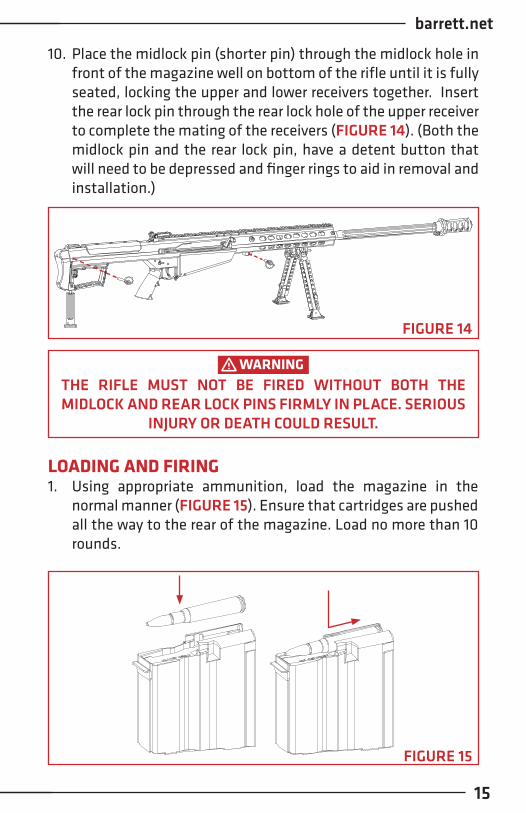
10. Place the midlock pin (shorter pin) through the midlock hole in front of the magazine well on bottom of the rifle until it is fully seated, locking the upper and lower receivers together. Insert the rear lock pin through the rear lock hole of the upper receiver to complete the mating of the receivers (FIGURE 14). (Both the midlock pin and the rear lock pin, have a detent button that will need to be depressed and finger rings to aid in removal and installation.)
THE RIFLE MUST NOT BE FIRED WITHOUT BOTH THE MIDLOCK AND REAR LOCK PINS FIRMLY IN PLACE. SERIOUS
INJURY OR DEATH COULD RESULT.
WARNING
FIGURE 14
LOADING AND FIRING1. Using appropriate ammunition, load the magazine in the
normal manner (FIGURE 15). Ensure that cartridges are pushed all the way to the rear of the magazine. Load no more than 10 rounds.
FIGURE 15

M107A1
16
FIGURE 16
3. Insert the magazine into the magazine well in the lower receiver, with magazine tilted at approximately a 45° angle (bullet tips upward). Insert the front of the magazine hook to its hinge, located in the front of the magazine well (1). Swing the rear of the magazine up until it locks into place by means of the magazine catch (2) (FIGURE 17). It should lock in with an audible click. Tug down on the magazine to ensure it is properly seated.
4. With the safety in the safe position (safety lever horizontal) and the muzzle pointed in safe direction pull the charging handle to the rear until it stops, then release it (do not keep your hand on the changing handle). The rifle then loads and locks under its own spring power for all subsequent rounds.
2. Ensure the safety lever is pointed towards SAFE (FIGURE 16).
1
2 FIGURE 17
MAGAZINE HINGE

barrett.net
17
DO NOT ATTEMPT TO FORCE A CARTRIDGE INTO THE CHAMBER BY FORCING THE BOLT CLOSED. IF THE BOLT DOES NOT CLOSE EASILY, REMOVE THE CARTRIDGE AND EXAMINE IT FOR DAMAGE OR DEFECTS. CHECK THE CHAMBER FOR
OBSTRUCTIONS.
WARNING
DOUBLE HEARING PROTECTION SHOULD BE WORN WHEN FIRING SINCE HARMFUL LEVELS OF NOISE ARE GENERATED.
WARNING
THE SHOOTER MUST BE POSITIONED DIRECTLY BEHIND THE RIFLE WITH THE RECOIL PAD HELD FIRMLY AGAINST THE SHOULDER. FIRING THE RIFLE IN ANY OTHER POSITION COULD RESULT IN INJURY BY CONTACT WITH THE RIFLE OR
RIFLE SCOPE.
WARNING
5. Because the rifle is recoil-operated, the shooter must be positioned squarely behind the rifle, with the recoil pad firmly against the shoulder. Anything less may result in injury, discomfort, or failure of the action to cycle correctly.
6. Rotate the safety to the FIRE position (FIGURE 18).
FIGURE 18

M107A1
18
7. The rifle may now be fired. The rifle will fire one round for each pull of the trigger, until the magazine and chamber are empty.
THE BOLT DOES NOT AUTOMATICALLY REMAIN TO THE REAR WHEN THE RIFLE OR MAGAZINE IS EMPTY. ALWAYS PULL THE CHARGING HANDLE TO THE REAR TO INSPECT
CHAMBER FOR AMMUNITION.
WARNING
8. After the magazine is emptied, or you are done firing, place the safety lever in the safe position with the muzzle pointed in a safe direction and remove magazine. Clear the firearm by pulling the charging handle to the rear several times; visually and physically check the chamber for ammunition.
UNLOADING AND CLEARING RIFLE1. Place the safety lever in the “SAFE” position.
2. Press the magazine catch forward, towards the magazine and remove the magazine (FIGURE 19).
FIGURE 19

barrett.net
19
UNLOADING THE MAGAZINE - FIGURE 211. Hold the magazine in either the right or
left hand, cartridges facing away from you.
2. Using the thumb of the other hand, push the cartridges forward and out one after another, until all are ejected.
3. Pull the charging handle to the rear, and visually and physically check the chamber for ammunition (FIGURE 20). Insert a chamber flag into the ejection port to indicate the rifle is clear.
FIGURE 20
RECENTLY FIRED BRASS MAY BE VERY HOTWARNING
FIGURE 21

M107A1
20
REMOVING THE MAINSPRING AND BUFFER1. Remove hydraulic buffer to expose buffer sleeve (FIGURE 22).
FIGURE 22
2. While maintaining constant control and pressure, rotate the buffer and spring to align the buffer notch with buffer stop on lower receiver (FIGURE 23).
3. Allow buffer sleeve and mainspring to fully extend then remove (FIGURE 24).
FIGURE 23
BUFFER STOP

barrett.net
21
FIGURE 24
INSTALLING THE MAINSPRING AND BUFFER1. Place buffer sleeve and mainspring into the lower receiver and
align the buffer sleeve notch with the welded buffer stop of the lower receiver. (FIGURE 25).
2. Push the buffer sleeve and mainspring into the lower receiver in one continuous, fluid motion. Once pushed past the buffer stop, rotate the buffer sleeve to align the notches vertically with the larger notch on top (FIGURE 26).
FIGURE 25
BUFFER STOP
BUFFER NOTCH
M107A1
22
FIGURE 26
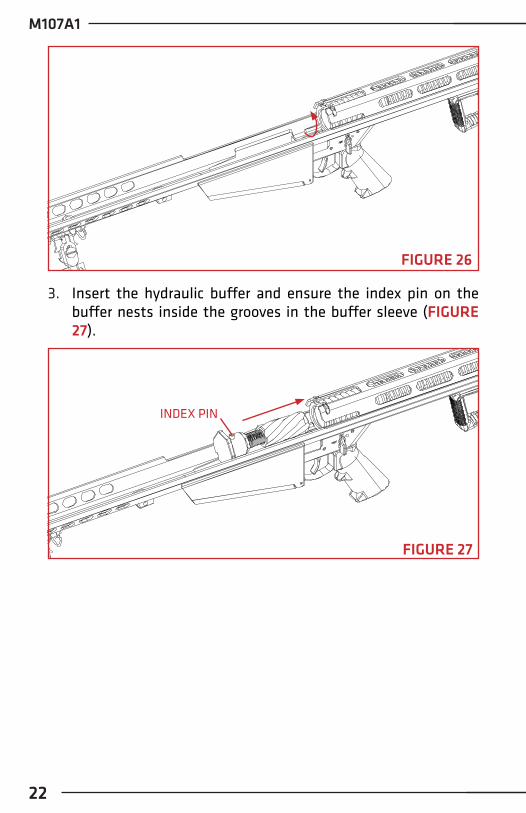
3. Insert the hydraulic buffer and ensure the index pin on the buffer nests inside the grooves in the buffer sleeve (FIGURE 27).
FIGURE 27
INDEX PIN

barrett.net
23
DO NOT INSERT CLEANING RODS THROUGH THE MUZZLE. THE BARREL CROWN COULD BE DAMAGED WHICH WOULD
SEVERELY DEGRADE THE ACCURACY OF THE RIFLE.
CAUTION
CLEANING AND LUBRICATION1. The rifle should be cleaned and lubricated after each shooting
session.
2. Apply cleaning solvent to a chamber brush and clean the chamber. Barrett Heavy Bore Cleaner is recommended.
3. Apply cleaning solvent to a bore brush and clean the bore. Barrett Heavy Bore Cleaner is recommended.
4. Clean the muzzle brake with a stiff plastic brush and bore solvent. It is best to clean the muzzle brake at the same time the barrel is being cleaned as the bore solvent will help loosen the carbon build-up on its interior walls.
5. Clean the bolt face with bore solvent. Use a stiff plastic brush to remove carbon from both the extractor and the ejector. Depress the ejector and extractor by hand to test for smooth function.
6. Use dry patches as necessary to remove cleaner from the bore and chamber.
7. Clean the remainder of the rifle with cotton-tipped swabs, general-purpose brushes and rags. Make sure all metal surfaces are coated with preservative oil.
UNLOAD AND CLEAR THE RIFLE BEFORE DISASSEMBLY.ENSURE NO LIVE AMMUNITION IS PRESENT DURING
DISASSEMBLY OR ASSEMBLY.
WARNING
M107A1
24
TO PROTECT THE RIFLE FROM CORROSION, THE RIFLE AND THE INTERIOR OF THE CARRYING CASE SHOULD BE MOISTURE FREE BEFORE THE RIFLE IS PLACED IN THE
CARRYING CASE FOR STORAGE.
GENERAL MAINTENANCE1. Ensure that all bearing surfaces and exposed parts, particularly
those listed below, are clean and properly lubricated:• Barrel• Bolt and bolt carrier• Mainspring housing• Trigger assembly• Transfer bar assembly• Lower receiver
2. Inspect all parts for looseness and tighten or replace, as necessary.• Inspect all parts (especially along welds) for cracks or
damage and replace, if necessary.• Each time the rifle is assembled for firing ensure that the
barrel, chamber, and locking lugs of the bolt are free of excess oil. When possible, an operational check using ten dummy rounds should be performed. Insert the dummy rounds into a magazine and load the magazine into the rifle. Manually operate the bolt carrier to the rear and forward, making sure the cartridges feed, extract, and eject properly. If the rifle is not functioning correctly, refer to the Troubleshooting section.
• Refer to the TROUBLESHOOTING section for Malfunction and Immediate Action Troubleshooting.
3. The magazine, chamber/bore, and firing pin channel should be free of cleaner, oil, grease, or other lubrication prior to use
WARNING

barrett.net
25
INSPECTION OF MAJOR COMPONENTS - FIGURE 28The rifle’s major groups are packaged as shown below:1. Upper Receiver2. Bolt Carrier Group3. Lower Receiver4. Magazine
Ensure all components are present and inspect for damage. Detailed inspection should be conducted as follows:
INSPECTION: THE UPPER RECEIVER - FIGURE 29
FIGURE 291. The barrel springs must not be overstretched, and each coil
should be tight, with no spaces between coils when the barrel key is not engaged into the barrel.
2. The battery and impact bumpers should be in good condition (not frayed, cracked, or twisted).
3. The muzzle brake should be tight and fully screwed on.
UNLOAD AND CLEAR THE RIFLE BEFORE INSPECTION. ENSURE NO LIVE AMMUNITION IS PRESENT DURING THE
INSPECTION AND TROUBLESHOOTING PROCESS.
WARNING
FIGURE 28
3
2
1
4

M107A1
26
4. The upper receiver should not be cracked, bent, or burred.
5. Check the front hinge pin slot in the front of the upper receiver to ensure that it is not deformed in any way.
6. The barrel should be clean and free of obstruction and oil.
7. All scope mountings should be tight, in good condition, and free of oil (iron sights, front and rear, may be lightly oiled at pivot points to prevent corrosion).
INSPECTION: THE BOLT CARRIER GROUP - FIGURE 30
2
14
5
63
FIGURE 30
7
1. Ejector (1) and extractor (2) must be checked to ensure they are under spring tension, and neither chipped nor worn and does not stick in one position.
2. De-cock the firing mechanism by using the rear lock pin to depress the sear (FIGURE 31). Avoid the cocking lever to reduce chance of being pinched during de-cocking. Manually work the bolt (4) in and out, feeling for any roughness, which may indicate wear, corrosion, or dirt/grit in the bolt carrier(5).
USE REAR LOCK PIN TO DE-COCK THE FIRING MECHANISM. AVOID THE COCKING LEVER TO REDUCE CHANCE OF BEING
PINCHED.
WARNING

barrett.net
27
SEAR
REAR LOCK PIN
FIGURE 31
3. Push the bolt into the carrier and inspect for firing-pin protrusion. Check firing-pin hole (on bolt face) to ensure it is not eroded or elongated. Bolt face should not be pitted.
4. Swing the cocking lever (6) forward. The sear (3) should capture the firing-pin extension before the cocking lever is fully depressed.
5. Manual Bolt Extender (7) slot should be free and clear of debris.

M107A1
28
INSPECTION: THE LOWER RECEIVER - FIGURE 32
FIGURE 32
1. With bolt carrier in place, pull it rearward and check to see that the mainspring moves freely (full travel) and is not deformed.
2. Hold bolt carrier back and down approximately ¼ inch (6 mm) under mainspring housing (sheet metal closure). With the thumb safety on fire, pull the trigger. Firing mechanism should function (a slight rise in bolt carrier is normal). If the housing is bent, the bolt carrier will rise excessively as the trigger is pulled, preventing proper functioning.
3. Lower receiver should not be cracked, bent, or burred.
4. Check the hinge pin at the front of the lower receiver to ensure that it is not cracked, bent, or deformed in any way.
5. Check bipod assembly for function and the mounting hardware is tight.

barrett.net
29
TROUBLESHOOTING
MALFUNCTION CAUSE CORRECTIVE ACTION
FAILURE TO FEED
Sluggish action Clean and lubricate or if cold check for over lubrication
Check Magazine:a. Proper
Installationb. Dirt/Debrisc. Damage
a. Reinstall magazine into the receiver
b. Clean magazinec. Replace magazine
Rifle short cycles Hold rifle more firmly in the shoulder
Bolt carrier assembly binds
Please contact Tech Support
Weak/broken mainspring
Replace mainspring
FAILURE TO CHAMBER
Check cartridge for damage
Remove damaged round
Check for dirty chamber
Clear and clean chamber
Check for faulty mainspring
Replace mainspring
Check for bent receiver
Please contact Tech Support
FAILURE TO COCK
Check bolt carrier for proper assembly, worn or missing parts
Replace worn or damaged partsReassemble correctly
M107A1
30
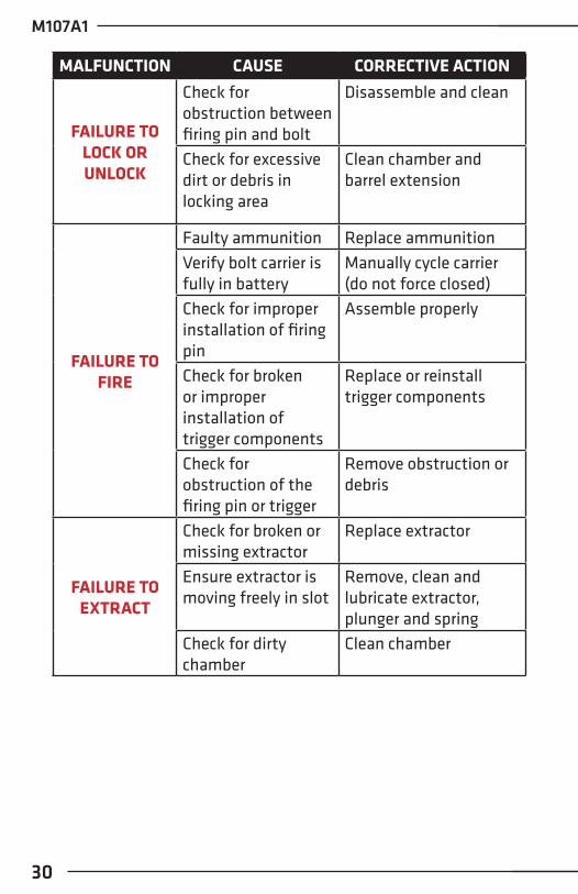
MALFUNCTION CAUSE CORRECTIVE ACTION
FAILURE TO LOCK OR UNLOCK
Check for obstruction between firing pin and bolt
Disassemble and clean
Check for excessive dirt or debris in locking area
Clean chamber and barrel extension
FAILURE TO FIRE
Faulty ammunition Replace ammunitionVerify bolt carrier is fully in battery
Manually cycle carrier (do not force closed)
Check for improper installation of firing pin
Assemble properly
Check for broken or improper installation of trigger components
Replace or reinstall trigger components
Check for obstruction of the firing pin or trigger
Remove obstruction or debris
FAILURE TO EXTRACT
Check for broken or missing extractor
Replace extractor
Ensure extractor is moving freely in slot
Remove, clean and lubricate extractor, plunger and spring
Check for dirty chamber
Clean chamber

barrett.net
31
MALFUNCTION CAUSE CORRECTIVE ACTION
FAILURE TO EJECT
Check for proper movement of ejector
Remove, clean, lubricate or replace ejector and/or spring as needed
VERY HARD RECOIL
Check for faulty/hot ammunition
Replace or cool ammunition
Check for damaged or missing mainspring/buffer
Replace/install mainspring or buffer as needed
Check for loose, missing, damaged/clogged muzzle brake
Please contact Tech Support
M107A1
32
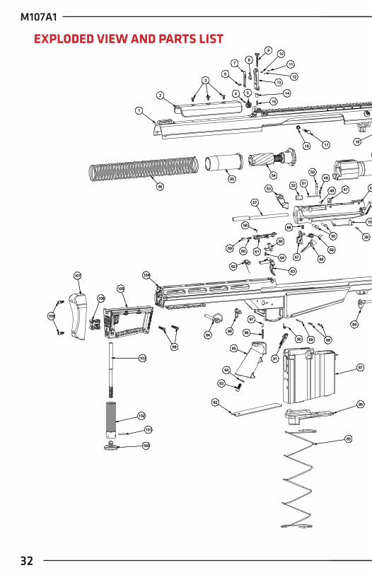
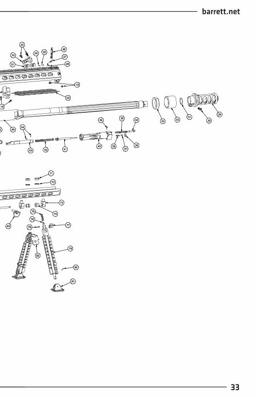
EXPLODED VIEW AND PARTS LIST
84
69
28
27
2931
19
3233343530
23
22
3637
38
21
52
39
40
25
39
73
74
24
41
82
72
53
71
98
42
44
86
85
43
20
75
87
76
26
48
78
45
18
79
70
46
92
19
91
68
47
77
81
95
94
93
49
66
96
67
97
50
51
63
64
65
57
62
54
58
6160
80
59
106
54
90 89
83
50
101
11
100
14
102
55
15
13
104
7
12
109
8
6
105
103
2
3
1
56
107
108
88
16
99
17
84
84
69
28
27
2931
19
3233343530
23
22
3637
38
21
52
39
40
25
39
73
74
24
41
82
72
53
71
98
42
44
86
85
43
20
75
87
76
26
48
78
45
18
79
70
46
92
19
91
68
47
77
81
95
94
93
49
66
96
67
97
50
51
63
64
65
57
62
54
58
6160
80
59
106
54
90 89
83
50
101
11
100
14
102
55
15
13
104
7
12
109
8
6
105
103
2
3
1
56
107
108
88
16
99
17
84
barrett.net
33
84
69
28
27
2931
19
3233343530
23
22
3637
38
21
52
39
40
25
39
73
74
24
41
82
72
53
71
98
42
44
86
85
43
20
75
87
76
26
48
78
45
18
79
70
46
92
19
91
68
47
77
81
95
94
93
49
66
96
67
97
50
51
63
64
65
57
62
54
58
6160
80
59
106
54
90 89
83
50
101
11
100
14
102
55
15
13
104
7
12
109
8
6
105
103
2
3
1
56
107
108
88
16
99
17
84
84
69
28
27
2931
19
3233343530
23
22
3637
38
21
52
39
40
25
39
73
74
24
41
82
72
53
71
98
42
44
86
85
43
20
75
87
76
26
48
78
45
18
79
70
46
92
19
91
68
47
77
81
95
94
93
49
66
96
67
97
50
51
63
64
65
57
62
54
58
6160
80
59
106
54
90 89
83
50
101
11
100
14
102
55
15
13
104
7
12
109
8
6
105
103
2
3
1
56
107
108
88
16
99
17
84

M107A1
34
ITEM
N
O.DE
SCRI
PTIO
NQT
Y.IT
EM
NO.
DESC
RIPT
ION
QTY.
ITEM
N
O.DE
SCRI
PTIO
NQT
Y.
1U
pper
Rec
eive
r Com
plet
e1
45.5
0 BM
G Ba
rrel C
ompl
ete
189
Mag
azin
e Ca
tch
Pin
1
2Ch
eek
piec
e1
46Bo
lt Ca
rrier
Com
plet
e1
90 M
agaz
ine
Catc
h Sp
ring
1
3Ch
eek
piec
e Sc
rew
347
Bolt
Inde
x Pi
n1
91M
ag. C
atch
1
4 W
inda
ge K
nob
Pin
148
Bolt
Inde
x Pi
n1
92M
ag. F
loor
Pla
te
1
5W
inda
ge K
nob
149
Acce
lera
tor S
prin
g Sc
rew
193
Pist
ol G
rip S
crew
1
6R
ear S
ight
Sca
le S
crew
150
Bol
t Car
rier P
in3
94Pi
stol
Grip
Sto
ck W
ashe
r1
7R
ear S
ight
Sca
le1
51Ac
cele
rato
r Spr
ing
195
Pist
ol G
rip1
8R
ear S
ight
Ape
rtur
e1
52Bo
lt Ex
tend
er1
96Sa
fety
Spr
ing
1
9El
evat
ion
Scre
w1
53Ac
cele
rato
r 1
97 S
afet
y De
tent
1
10El
evat
ion
Scre
w S
prin
g 1
54H
ydra
ulic
Rec
oil B
uffer
Ass
y.1
98Sa
fety
1
11El
evat
ion
Scre
w P
in
155
Buff
er S
leev
e1
9910
-32
X 1.2
5 SH
CS T
OR
X2
12El
evat
ion
Scre
w B
all
156
Mai
n Sp
ring
110
0M
onop
od R
otat
ing
Foot
Low
er1
13R
ear S
ight
Bod
y1
57Ac
cele
rato
r Rod
1
101
1/8
X 3/
4 Sp
lit P
in S
tain
less
1
14R
ear S
ight
Bas
e De
tent
158
Tran
sfer
Bar
Pin
110
2M
onop
od R
otat
ing
Foot
Upp
er1
15R
ear S
ight
Spr
ing
159
Tran
sfer
Bar
Det
ent
110
3M
onop
od E
leva
tion
Scre
w1
16 W
inda
ge S
crew
Spr
ing
160
Tra
nsfe
r Bar
Spr
ing
110
4Lo
wer
Rec
eive
r Com
plet
e1
17W
inda
ge S
crew
161
Tran
sfer
Bar
110
5R
ear G
rip1
18Ba
rrel K
ey
162
Trig
ger S
prin
g1
106
Mon
opod
Loc
k Kn
ob1
19Ba
rrel S
prin
g Sc
rew
463
Trig
ger
110
7R
ecoi
l Pad
1
20Ba
rrel S
prin
g 2
64Di
scon
nect
or S
prin
g1
108
Rec
oil P
ad S
crew
2
21Ce
nter
Nut
Pla
te2
65Di
scon
nect
or
1
22Fr
ont S
ling
Loop
166
Sear
Spr
ing
1
2310
-32
x.50
BH
CS2
67 S
ear A
ssem
bly
1
24Fr
ont S
ight
Cat
ch P
in1
68Co
ckin
g Le
ver
1
25Fr
ont S
ight
Pin
169
Coc
king
Lev
er S
prin
g1
26Fr
ont S
ight
170
Cam
Pin
Ass
embl
y1
27Fr
ont S
ight
Spr
ing
171
Yoke
mou
nt N
ut2
28Fr
ont S
ight
Cat
ch1
72 Y
oke
Mou
nt W
ashe
r2
29M
uzzl
e Br
ake
173
Yoke
Mou
nt2
30M
uzzl
e Br
ake
Scre
w1
74Bi
pod
Shim
Bus
hing
2
31M
uzzl
e Br
ake
Shim
Kit
175
Bipo
d Sp
ring
2
32Im
pact
, Bar
rel B
umpe
r1
76 B
ipod
Det
ent
2
33 B
atte
ry B
umpe
r1
77Bi
pod
Pin
2
34H
ard
Stop
Eje
ctor
178
Bipo
d Sc
rew
2
35Ej
ecto
r Spr
ing
179
Bipo
d Le
g2
36Ex
trac
tor
180
RP
- .12
5 DI
A. x
.625
2
37Ex
trac
tor P
lung
er1
81Fo
ot S
hoe
2
38Ex
trac
tor S
prin
g1
82Bi
pod
Yoke
1
39Ca
m /
Eje
ctor
Pin
283
Mid
lock
Pin
1
40Bo
lt 1
84R
ear L
ock
Pin
2
41Fi
ring
Pin
1
85M
agaz
ine
Sprin
g1
42Fi
ring
Pin
Exte
nsio
n Sp
ring
186
Mag
azin
e Fo
llow
er
1
43Fi
ring
Pin
Exte
nsio
n 1
87M
agaz
ine
1
44Fi
ring
Pin
Pin
288
Trig
ger H
ousi
ng P
in2

barrett.net
35
ITEM
N
O.DE
SCRI
PTIO
NQT
Y.IT
EM
NO.
DESC
RIPT
ION
QTY.
ITEM
N
O.DE
SCRI
PTIO
NQT
Y.
1U
pper
Rec
eive
r Com
plet
e1
45.5
0 BM
G Ba
rrel C
ompl
ete
189
Mag
azin
e Ca
tch
Pin
1
2Ch
eek
piec
e1
46Bo
lt Ca
rrier
Com
plet
e1
90 M
agaz
ine
Catc
h Sp
ring
1
3Ch
eek
piec
e Sc
rew
347
Bolt
Inde
x Pi
n1
91M
ag. C
atch
1
4 W
inda
ge K
nob
Pin
148
Bolt
Inde
x Pi
n1
92M
ag. F
loor
Pla
te
1
5W
inda
ge K
nob
149
Acce
lera
tor S
prin
g Sc
rew
193
Pist
ol G
rip S
crew
1
6R
ear S
ight
Sca
le S
crew
150
Bol
t Car
rier P
in3
94Pi
stol
Grip
Sto
ck W
ashe
r1
7R
ear S
ight
Sca
le1
51Ac
cele
rato
r Spr
ing
195
Pist
ol G
rip1
8R
ear S
ight
Ape
rtur
e1
52Bo
lt Ex
tend
er1
96Sa
fety
Spr
ing
1
9El
evat
ion
Scre
w1
53Ac
cele
rato
r 1
97 S
afet
y De
tent
1
10El
evat
ion
Scre
w S
prin
g 1
54H
ydra
ulic
Rec
oil B
uffer
Ass
y.1
98Sa
fety
1
11El
evat
ion
Scre
w P
in
155
Buff
er S
leev
e1
9910
-32
X 1.2
5 SH
CS T
OR
X2
12El
evat
ion
Scre
w B
all
156
Mai
n Sp
ring
110
0M
onop
od R
otat
ing
Foot
Low
er1
13R
ear S
ight
Bod
y1
57Ac
cele
rato
r Rod
1
101
1/8
X 3/
4 Sp
lit P
in S
tain
less
1
14R
ear S
ight
Bas
e De
tent
158
Tran
sfer
Bar
Pin
110
2M
onop
od R
otat
ing
Foot
Upp
er1
15R
ear S
ight
Spr
ing
159
Tran
sfer
Bar
Det
ent
110
3M
onop
od E
leva
tion
Scre
w1
16 W
inda
ge S
crew
Spr
ing
160
Tra
nsfe
r Bar
Spr
ing
110
4Lo
wer
Rec
eive
r Com
plet
e1
17W
inda
ge S
crew
161
Tran
sfer
Bar
110
5R
ear G
rip1
18Ba
rrel K
ey
162
Trig
ger S
prin
g1
106
Mon
opod
Loc
k Kn
ob1
19Ba
rrel S
prin
g Sc
rew
463
Trig
ger
110
7R
ecoi
l Pad
1
20Ba
rrel S
prin
g 2
64Di
scon
nect
or S
prin
g1
108
Rec
oil P
ad S
crew
2
21Ce
nter
Nut
Pla
te2
65Di
scon
nect
or
1
22Fr
ont S
ling
Loop
166
Sear
Spr
ing
1
2310
-32
x.50
BH
CS2
67 S
ear A
ssem
bly
1
24Fr
ont S
ight
Cat
ch P
in1
68Co
ckin
g Le
ver
1
25Fr
ont S
ight
Pin
169
Coc
king
Lev
er S
prin
g1
26Fr
ont S
ight
170
Cam
Pin
Ass
embl
y1
27Fr
ont S
ight
Spr
ing
171
Yoke
mou
nt N
ut2
28Fr
ont S
ight
Cat
ch1
72 Y
oke
Mou
nt W
ashe
r2
29M
uzzl
e Br
ake
173
Yoke
Mou
nt2
30M
uzzl
e Br
ake
Scre
w1
74Bi
pod
Shim
Bus
hing
2
31M
uzzl
e Br
ake
Shim
Kit
175
Bipo
d Sp
ring
2
32Im
pact
, Bar
rel B
umpe
r1
76 B
ipod
Det
ent
2
33 B
atte
ry B
umpe
r1
77Bi
pod
Pin
2
34H
ard
Stop
Eje
ctor
178
Bipo
d Sc
rew
2
35Ej
ecto
r Spr
ing
179
Bipo
d Le
g2
36Ex
trac
tor
180
RP
- .12
5 DI
A. x
.625
2
37Ex
trac
tor P
lung
er1
81Fo
ot S
hoe
2
38Ex
trac
tor S
prin
g1
82Bi
pod
Yoke
1
39Ca
m /
Eje
ctor
Pin
283
Mid
lock
Pin
1
40Bo
lt 1
84R
ear L
ock
Pin
2
41Fi
ring
Pin
1
85M
agaz
ine
Sprin
g1
42Fi
ring
Pin
Exte
nsio
n Sp
ring
186
Mag
azin
e Fo
llow
er
1
43Fi
ring
Pin
Exte
nsio
n 1
87M
agaz
ine
1
44Fi
ring
Pin
Pin
288
Trig
ger H
ousi
ng P
in2

M107A1
36
NOTES

M10
7A1
P.O. Box 1077 Murfreesboro, TN 37133 USA
615.896.2938615.896.7313 fax
barrett.net
P/N 16693
Recommended