MAHARASHTRA STATE BOARD OF TECHNICAL EDUCATION
Subject Code : 12143 (SAP)
Important Instructions to examiners:
1) The answers should be examined by key words and not as word
scheme.
2) The model answer and the answer written by candidate may vary but the examiner may should assess
the understanding level of the candidate.
3) The language errors such as grammatical, spelling errors should not be given more importance
applicable for subject English and Communication Skills).
4) While assessing figures, examiner may give credit for principal
The figures drawn by candidate and model answer may vary. The examiner may give credit for any
equivalent figure drawn.
5) Credits may be given step wise for numerical problems. In some cases, the assumed constant value
may vary and there may be some difference in the candidate’s answers and model answer.
6) In case of some questions credit may be given by judgement on part of examiner of relevant answer
based on candidate’s understanding.
7) For programming language papers, credit may be given to any other program based o on equivalent
concept.
MAHARASHTRA STATE BOARD OF TECHNICAL EDUCATION
(Autonomous)
(ISO/IEC-27001-2005 Certified)
Summer – 2014 Examinations
Subject Code : 12143 (SAP) Model Answer
Important Instructions to examiners:
1) The answers should be examined by key words and not as word-to-word as given in the model answer
2) The model answer and the answer written by candidate may vary but the examiner may should assess
anding level of the candidate.
3) The language errors such as grammatical, spelling errors should not be given more importance
applicable for subject English and Communication Skills).
4) While assessing figures, examiner may give credit for principal components indicated in the figure.
The figures drawn by candidate and model answer may vary. The examiner may give credit for any
5) Credits may be given step wise for numerical problems. In some cases, the assumed constant value
may vary and there may be some difference in the candidate’s answers and model answer.
6) In case of some questions credit may be given by judgement on part of examiner of relevant answer
based on candidate’s understanding.
pers, credit may be given to any other program based o on equivalent
MAHARASHTRA STATE BOARD OF TECHNICAL EDUCATION
Page No : 1 of 24
word as given in the model answer
2) The model answer and the answer written by candidate may vary but the examiner may should assess
3) The language errors such as grammatical, spelling errors should not be given more importance (Not
components indicated in the figure.
The figures drawn by candidate and model answer may vary. The examiner may give credit for any
5) Credits may be given step wise for numerical problems. In some cases, the assumed constant values
may vary and there may be some difference in the candidate’s answers and model answer.
6) In case of some questions credit may be given by judgement on part of examiner of relevant answer
pers, credit may be given to any other program based o on equivalent
MAHARASHTRA STATE BOARD OF TECHNICAL EDUCATION
Subject Code : 12143 (SAP)
1 a) Attempt any three:
1 a) i) State importance of following switchgear elements of protective elements.
1) Fuse
2) Isolator
3) Circuit breaker
4) Relay
Ans:
Fuse: provides short circuit protection.
Isolator: Theses are used in addition with circuit breakers and are provided on each side
of every C.B. to provide isolation and enable maintenance,
isolate a power system element such as transformer etc
only after operating the CB.
Circuit breaker: It performs interruption function. Its function is to make or break the
circuit manually or remotely under normal condition and automatically under fault
condition, used to switch and bring the power system components in circuit, protect the
related sections from any abnormal conditions of operation such as overload, over voltage,
overcurrent, earth faults, phase to phase faults, under frequency etc.
Relay: used to give suitable signals for certain
overcurrent, faults, switching etc. to circuit breaker mechanism for operation.
1 a) ii) Explain with neat sketch the action of arc runners and arc splitters in Air
Ans:
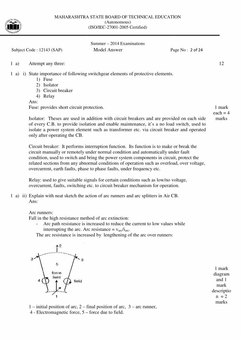
Arc runners:
Fall in the high resistance method of arc extinction:
- Arc path resistance is increased to reduce the current to low values while
interrupting the arc. Arc resistance = v
The arc resistance is increased by lengthening of the
1 – initial position of arc, 2 – final position of arc, 3
4 - Electromagnetic force, 5 –
MAHARASHTRA STATE BOARD OF TECHNICAL EDUCATION
(Autonomous)
(ISO/IEC-27001-2005 Certified)
Summer – 2014 Examinations
Subject Code : 12143 (SAP) Model Answer Page No :
State importance of following switchgear elements of protective elements.
circuit protection.
Theses are used in addition with circuit breakers and are provided on each side
of every C.B. to provide isolation and enable maintenance, it’s a no load switch, used to
isolate a power system element such as transformer etc. via circuit breaker and operated
It performs interruption function. Its function is to make or break the
circuit manually or remotely under normal condition and automatically under fault
switch and bring the power system components in circuit, protect the
related sections from any abnormal conditions of operation such as overload, over voltage,
overcurrent, earth faults, phase to phase faults, under frequency etc.
table signals for certain conditions such as low/no voltage,
overcurrent, faults, switching etc. to circuit breaker mechanism for operation.
Explain with neat sketch the action of arc runners and arc splitters in Air CB.
Fall in the high resistance method of arc extinction:
Arc path resistance is increased to reduce the current to low values while
interrupting the arc. Arc resistance = varc/iarc.
increased by lengthening of the arc over runners:
final position of arc, 3 – arc runner,
– force due to field.
MAHARASHTRA STATE BOARD OF TECHNICAL EDUCATION
Page No : 2 of 24
12
Theses are used in addition with circuit breakers and are provided on each side
it’s a no load switch, used to
. via circuit breaker and operated
It performs interruption function. Its function is to make or break the
circuit manually or remotely under normal condition and automatically under fault
switch and bring the power system components in circuit, protect the
related sections from any abnormal conditions of operation such as overload, over voltage,
conditions such as low/no voltage,
overcurrent, faults, switching etc. to circuit breaker mechanism for operation.
1 mark
each = 4
marks
CB.
Arc path resistance is increased to reduce the current to low values while
1 mark
diagram
and 1
mark
descriptio
n = 2
marks
MAHARASHTRA STATE BOARD OF TECHNICAL EDUCATION
Subject Code : 12143 (SAP)
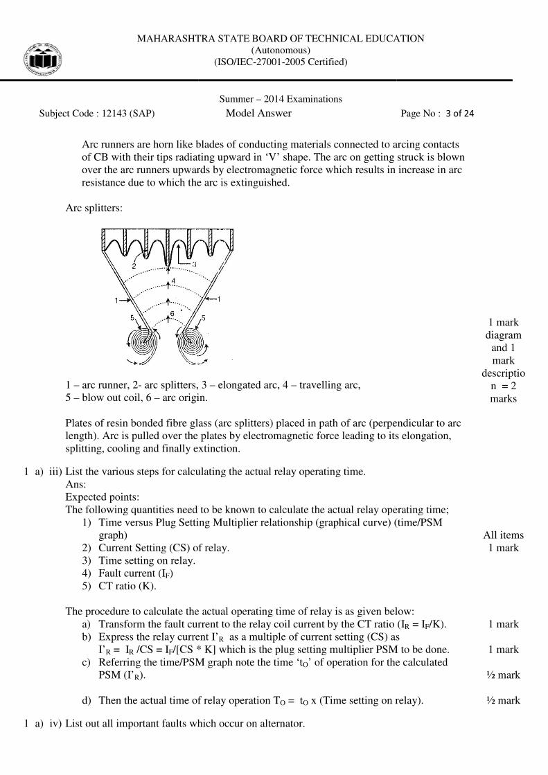
Arc runners are horn like blades of conducting materials connected to arcing contacts
of CB with their tips radiating upward in ‘V’ shape. The arc on getting struck is blown
over the arc runners upwards by electromagnetic force which results in increase in arc
resistance due to which the arc is extinguished.
Arc splitters:
1 – arc runner, 2- arc splitters,
5 – blow out coil, 6 – arc origin.
Plates of resin bonded fibre glass (arc splitters) placed in path of arc (perpendicular to arc
length). Arc is pulled over the plates by electromagnetic force leading to its elonga
splitting, cooling and finally extinction.
1 a) iii) List the various steps for calculating the actual relay operating ti
Ans:
Expected points:
The following quantities need to be known to calculate the actual relay operating time
1) Time versus Plug Setting Multiplier relationship (graphical curve) (time/PSM
graph)
2) Current Setting (CS) of relay.
3) Time setting on relay.
4) Fault current (IF)
5) CT ratio (K).
The procedure to calculate the actual operating time of relay is as given below:
a) Transform the fault current to the relay coil current by the CT ratio (I
b) Express the relay current I’
I’R = IR /CS = IF/[CS * K] which is the plug setting multiplier PSM to be done.
c) Referring the time/PSM graph note the time ‘t
PSM (I’R).
d) Then the actual time of relay operation T
1 a) iv) List out all important faults which occur on alternator.
MAHARASHTRA STATE BOARD OF TECHNICAL EDUCATION
(Autonomous)
(ISO/IEC-27001-2005 Certified)
Summer – 2014 Examinations
Subject Code : 12143 (SAP) Model Answer
Arc runners are horn like blades of conducting materials connected to arcing contacts
radiating upward in ‘V’ shape. The arc on getting struck is blown
over the arc runners upwards by electromagnetic force which results in increase in arc
resistance due to which the arc is extinguished.
arc splitters, 3 – elongated arc, 4 – travelling arc,
arc origin.
Plates of resin bonded fibre glass (arc splitters) placed in path of arc (perpendicular to arc
Arc is pulled over the plates by electromagnetic force leading to its elonga
splitting, cooling and finally extinction.
List the various steps for calculating the actual relay operating time.
The following quantities need to be known to calculate the actual relay operating time
Time versus Plug Setting Multiplier relationship (graphical curve) (time/PSM
Current Setting (CS) of relay.
The procedure to calculate the actual operating time of relay is as given below:
Transform the fault current to the relay coil current by the CT ratio (I
Express the relay current I’R as a multiple of current setting (CS) as
/[CS * K] which is the plug setting multiplier PSM to be done.
Referring the time/PSM graph note the time ‘tO’ of operation for the calculated
Then the actual time of relay operation TO = tO x (Time setting on relay
List out all important faults which occur on alternator.
MAHARASHTRA STATE BOARD OF TECHNICAL EDUCATION
Page No : 3 of 24
Arc runners are horn like blades of conducting materials connected to arcing contacts
radiating upward in ‘V’ shape. The arc on getting struck is blown
over the arc runners upwards by electromagnetic force which results in increase in arc
Plates of resin bonded fibre glass (arc splitters) placed in path of arc (perpendicular to arc
Arc is pulled over the plates by electromagnetic force leading to its elongation,
1 mark
diagram
and 1
mark
descriptio
n = 2
marks
The following quantities need to be known to calculate the actual relay operating time;
Time versus Plug Setting Multiplier relationship (graphical curve) (time/PSM
The procedure to calculate the actual operating time of relay is as given below:
Transform the fault current to the relay coil current by the CT ratio (IR = IF/K).
g (CS) as
/[CS * K] which is the plug setting multiplier PSM to be done.
’ of operation for the calculated
(Time setting on relay).
All items
1 mark
1 mark
1 mark
½ mark
½ mark
MAHARASHTRA STATE BOARD OF TECHNICAL EDUCATION
Subject Code : 12143 (SAP)
Ans:
Under frequency
Rotor earth fault.
Over voltages
Thermal over loading
Alternator bus bar faults as short circuit.
Stator winding earth fault.
Stator winding turn short fault
Stator winding phase to phase fault
Field system open circuit
1 b) Attempt any one:
1 b) i) Explain with neat diagram construction and working of vacuum CB
applications of VCB.
Ans:
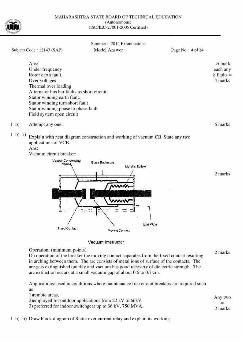
Vacuum circuit breaker:
Operation: (minimum points)
On operation of the breaker the moving contact separates from the fixed contact resulting
in arching between them. The arc consists of metal ions of surface of
arc gets extinguished quickly and vacuum has good recovery of dielectric strength. The
arc extinction occurs at a small vacuum gap of about 0.6 to 0.7 cm.
Applications: used in conditions where maintenance free circuit breakers are re
as
1)remote areas,
2)employed for outdoor applications from 22 kV to 66kV
3) preferred for indoor switchgear up to 36 kV, 750 MVA.
1 b) ii) Draw block diagram of Static over
MAHARASHTRA STATE BOARD OF TECHNICAL EDUCATION
(Autonomous)
(ISO/IEC-27001-2005 Certified)
Summer – 2014 Examinations
Subject Code : 12143 (SAP) Model Answer Page No :
as short circuit.
Stator winding turn short fault
Stator winding phase to phase fault
Explain with neat diagram construction and working of vacuum CB. State any two
On operation of the breaker the moving contact separates from the fixed contact resulting
in arching between them. The arc consists of metal ions of surface of the contacts. The
arc gets extinguished quickly and vacuum has good recovery of dielectric strength. The
arc extinction occurs at a small vacuum gap of about 0.6 to 0.7 cm.
Applications: used in conditions where maintenance free circuit breakers are re
2)employed for outdoor applications from 22 kV to 66kV
3) preferred for indoor switchgear up to 36 kV, 750 MVA.
Draw block diagram of Static over current relay and explain its working.
MAHARASHTRA STATE BOARD OF TECHNICAL EDUCATION
Page No : 4 of 24
½ mark
each any
8 faults =
4 marks
6 marks
. State any two
On operation of the breaker the moving contact separates from the fixed contact resulting
the contacts. The
arc gets extinguished quickly and vacuum has good recovery of dielectric strength. The
Applications: used in conditions where maintenance free circuit breakers are required such
2 marks
2 marks
Any two
=
2 marks
MAHARASHTRA STATE BOARD OF TECHNICAL EDUCATION
Subject Code : 12143 (SAP)
Ans:
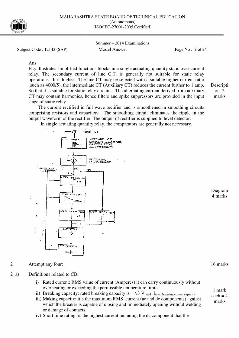
Fig. illustrates simplified functions blocks in a single actuating quantity static over current
relay. The secondary current of line C.T. is generally not suitable for static relay
operations. It is higher. The line
(such as 4000/5), the intermediate CT (Auxiliary CT) reduces the current further to 1 amp.
So that it is suitable for static relay circuits. The alternating current derived from auxiliary
CT may contain harmonics, hence filters and spike suppressors are provided in the input
stage of static relay.
The current rectified in full wave rectifier and is smoothened in smoothing circuits
comprising resistors and capacitors. The smoothing circuit e
output waveform of the rectifier. The output of rectifier is supplied to level detector.
In single actuating quantity relay, the comparators are generally not necessary.
2 Attempt any four:
2 a) Definitions related to CB:
i) Rated current: RMS value of
overheating or exceeding the permissible temperature limits.
ii) Breaking capacity: rated brea
iii) Making capacity: it’s the maximum RMS current (ac and dc components) against
which the breaker is capable of closing and immediately opening without welding
or damage of contacts.
iv) Short time rating: is the highest current including the dc component that the
MAHARASHTRA STATE BOARD OF TECHNICAL EDUCATION
(Autonomous)
(ISO/IEC-27001-2005 Certified)
Summer – 2014 Examinations
Subject Code : 12143 (SAP) Model Answer
Fig. illustrates simplified functions blocks in a single actuating quantity static over current
relay. The secondary current of line C.T. is generally not suitable for static relay
operations. It is higher. The line CT may be selected with a suitable higher current ratio
(such as 4000/5), the intermediate CT (Auxiliary CT) reduces the current further to 1 amp.
So that it is suitable for static relay circuits. The alternating current derived from auxiliary
tain harmonics, hence filters and spike suppressors are provided in the input
The current rectified in full wave rectifier and is smoothened in smoothing circuits
comprising resistors and capacitors. The smoothing circuit eliminates the ripple in the
output waveform of the rectifier. The output of rectifier is supplied to level detector.
In single actuating quantity relay, the comparators are generally not necessary.
RMS value of current (Amperes) it can carry continuously without
or exceeding the permissible temperature limits.
rated breaking capacity is = √3 Vrated Irated breaking current capacity.
Making capacity: it’s the maximum RMS current (ac and dc components) against
which the breaker is capable of closing and immediately opening without welding
is the highest current including the dc component that the
MAHARASHTRA STATE BOARD OF TECHNICAL EDUCATION
Page No : 5 of 24
Fig. illustrates simplified functions blocks in a single actuating quantity static over current
relay. The secondary current of line C.T. is generally not suitable for static relay
CT may be selected with a suitable higher current ratio
(such as 4000/5), the intermediate CT (Auxiliary CT) reduces the current further to 1 amp.
So that it is suitable for static relay circuits. The alternating current derived from auxiliary
tain harmonics, hence filters and spike suppressors are provided in the input
The current rectified in full wave rectifier and is smoothened in smoothing circuits
liminates the ripple in the
output waveform of the rectifier. The output of rectifier is supplied to level detector.
In single actuating quantity relay, the comparators are generally not necessary.
Descripti
on 2
marks
Diagram
4 marks
16 marks
it can carry continuously without
rated breaking current capacity.
Making capacity: it’s the maximum RMS current (ac and dc components) against
which the breaker is capable of closing and immediately opening without welding
is the highest current including the dc component that the
1 mark
each = 4
marks
MAHARASHTRA STATE BOARD OF TECHNICAL EDUCATION
Subject Code : 12143 (SAP)
breaker shall be required to carry without damage for the specified time interval.
2 b) Explain working of ELCB:
Ans:
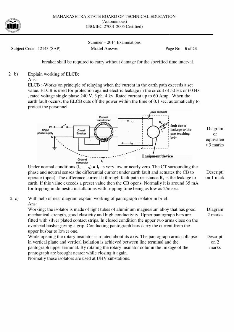
ELCB :-Works on principle of relaying when t
value. ELCB is used for protection against electric leakage in the circuit of 50 Hz or 60 Hz
, rated voltage single phase 240 V, 3 ph. 4 kv. Rated current up to 60 Amp.
earth fault occurs, the ELCB cuts
protect the personnel.
Under normal conditions (IL –
phase and neutral senses the differential current under earth fault and actuates
operate (open). The difference current I
earth. If this value exceeds a preset value then the CB opens. Normally it is around 35 mA
for tripping in domestic installations with tripping time bei
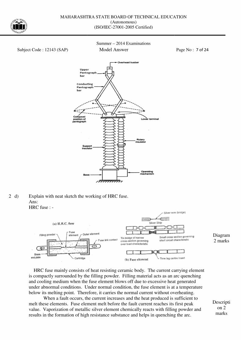
2 c) With help of neat diagram explain working of pantograph isolator in brief.
Ans:
Working: the isolator is made of light tubes of aluminum magnesium alloy that has
mechanical strength, good elasticity and high conductivity. Upper pantograph bars are
fitted with silver plated contact strips. In closed condition the upper two arms close on the
overhead busbar giving a grip.
upper busbar to lower one.
While opening the rotary insulator is rotated about its axis. The pantograph arms collapse
in vertical plane and vertical isolation is achieved between line terminal and the
pantograph upper terminal. By rotating th
pantograph are brought nearer while closing it again.
Normally these isolators are used at UHV substations.
MAHARASHTRA STATE BOARD OF TECHNICAL EDUCATION
(Autonomous)
(ISO/IEC-27001-2005 Certified)
Summer – 2014 Examinations
Subject Code : 12143 (SAP) Model Answer Page No :
breaker shall be required to carry without damage for the specified time interval.
Works on principle of relaying when the current in the earth path exceeds a set
ELCB is used for protection against electric leakage in the circuit of 50 Hz or 60 Hz
, rated voltage single phase 240 V, 3 ph. 4 kv. Rated current up to 60 Amp.
earth fault occurs, the ELCB cuts off the power within the time of 0.1 sec. automatically to
– IN) = If is very low or nearly zero. The CT surrounding the
phase and neutral senses the differential current under earth fault and actuates
operate (open). The difference current If through fault path resistance Re is the leakage to
earth. If this value exceeds a preset value then the CB opens. Normally it is around 35 mA
for tripping in domestic installations with tripping time being as low as 25msec.
With help of neat diagram explain working of pantograph isolator in brief.
Working: the isolator is made of light tubes of aluminum magnesium alloy that has
mechanical strength, good elasticity and high conductivity. Upper pantograph bars are
fitted with silver plated contact strips. In closed condition the upper two arms close on the
overhead busbar giving a grip. Conducting pantograph bars carry the current from the
While opening the rotary insulator is rotated about its axis. The pantograph arms collapse
in vertical plane and vertical isolation is achieved between line terminal and the
pantograph upper terminal. By rotating the rotary insulator column the linkage of the
pantograph are brought nearer while closing it again.
Normally these isolators are used at UHV substations.
MAHARASHTRA STATE BOARD OF TECHNICAL EDUCATION
Page No : 6 of 24
breaker shall be required to carry without damage for the specified time interval.
he current in the earth path exceeds a set
ELCB is used for protection against electric leakage in the circuit of 50 Hz or 60 Hz
, rated voltage single phase 240 V, 3 ph. 4 kv. Rated current up to 60 Amp. When the
ime of 0.1 sec. automatically to
is very low or nearly zero. The CT surrounding the
phase and neutral senses the differential current under earth fault and actuates the CB to
is the leakage to
earth. If this value exceeds a preset value then the CB opens. Normally it is around 35 mA
25msec.
Diagram
or
equivalen
t 3 marks
Descripti
on 1 mark
Working: the isolator is made of light tubes of aluminum magnesium alloy that has good
mechanical strength, good elasticity and high conductivity. Upper pantograph bars are
fitted with silver plated contact strips. In closed condition the upper two arms close on the
rent from the
While opening the rotary insulator is rotated about its axis. The pantograph arms collapse
in vertical plane and vertical isolation is achieved between line terminal and the
e rotary insulator column the linkage of the
Diagram
2 marks
Descripti
on 2
marks
MAHARASHTRA STATE BOARD OF TECHNICAL EDUCATION
Subject Code : 12143 (SAP)
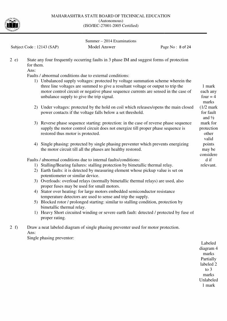
2 d) Explain with neat sketch the w
Ans:
HRC fuse : -
HRC fuse mainly consists of heat resisting ceramic body. The current carrying element
is compactly surrounded by the filling powder. Filling material acts as an arc quenching
and cooling medium when the fuse e
under abnormal conditions. Under no
below its melting point. Therefore, it carries the normal current without overheating.
When a fault occurs, the current increases and the heat produced is sufficient to
melt these elements. Fuse element melt before the fault current rea
value. Vaporization of metallic
results in the formation of high resista
MAHARASHTRA STATE BOARD OF TECHNICAL EDUCATION
(Autonomous)
(ISO/IEC-27001-2005 Certified)
Summer – 2014 Examinations
Subject Code : 12143 (SAP) Model Answer
Explain with neat sketch the working of HRC fuse.
HRC fuse mainly consists of heat resisting ceramic body. The current carrying element
is compactly surrounded by the filling powder. Filling material acts as an arc quenching
and cooling medium when the fuse element blows off due to excessive heat g
ormal conditions. Under normal condition, the fuse element is at a temperature
. Therefore, it carries the normal current without overheating.
rs, the current increases and the heat produced is sufficient to
melt these elements. Fuse element melt before the fault current reaches its first peak
metallic silver element chemically reacts with filling powder and
e formation of high resistance substance and helps in quenching
MAHARASHTRA STATE BOARD OF TECHNICAL EDUCATION
Page No : 7 of 24
HRC fuse mainly consists of heat resisting ceramic body. The current carrying element
is compactly surrounded by the filling powder. Filling material acts as an arc quenching
ws off due to excessive heat generated
n, the fuse element is at a temperature
. Therefore, it carries the normal current without overheating.
rs, the current increases and the heat produced is sufficient to
s its first peak
silver element chemically reacts with filling powder and
nce substance and helps in quenching the arc.
Diagram
2 marks
Descripti
on 2
marks
MAHARASHTRA STATE BOARD OF TECHNICAL EDUCATION
Subject Code : 12143 (SAP)
2 e) State any four frequently occurring faults in 3 phase IM and suggest forms of protection
for them.
Ans:
Faults / abnormal conditions due to external conditions:
1) Unbalanced supply voltages:
three line voltages are summed to give a resultant voltage or output to trip the
motor control circuit or negative phase sequence currents
unbalance supply to give the trip signal.
2) Under voltages: protected by the hold on coil which releases/opens the main closed
power contacts if the voltage falls below a set threshold.
3) Reverse phase sequence starting:
supply the motor control circuit does not energize till pr
restored thus motor is protected.
4) Single phasing: protected by single phasing preventer which prevents energizing
the motor circuit till all the phases are healthy restored.
Faults / abnormal conditions due to internal
1) Stalling/Bearing failures:
2) Earth faults: it is detected by measuring element whose pickup value is set
potentiometer or similar device.
3) Overloads: overload relays (normally bimetallic thermal relays) are used
proper fuses may be used for small motors.
4) Stator over heating: for large motors embedded semiconductor resistance
temperature detectors are
5) Blocked rotor / prolonged starting:
bimetallic thermal relay.
1) Heavy Short circuited winding or severe earth fault: detected / protected by fuse of
proper rating.
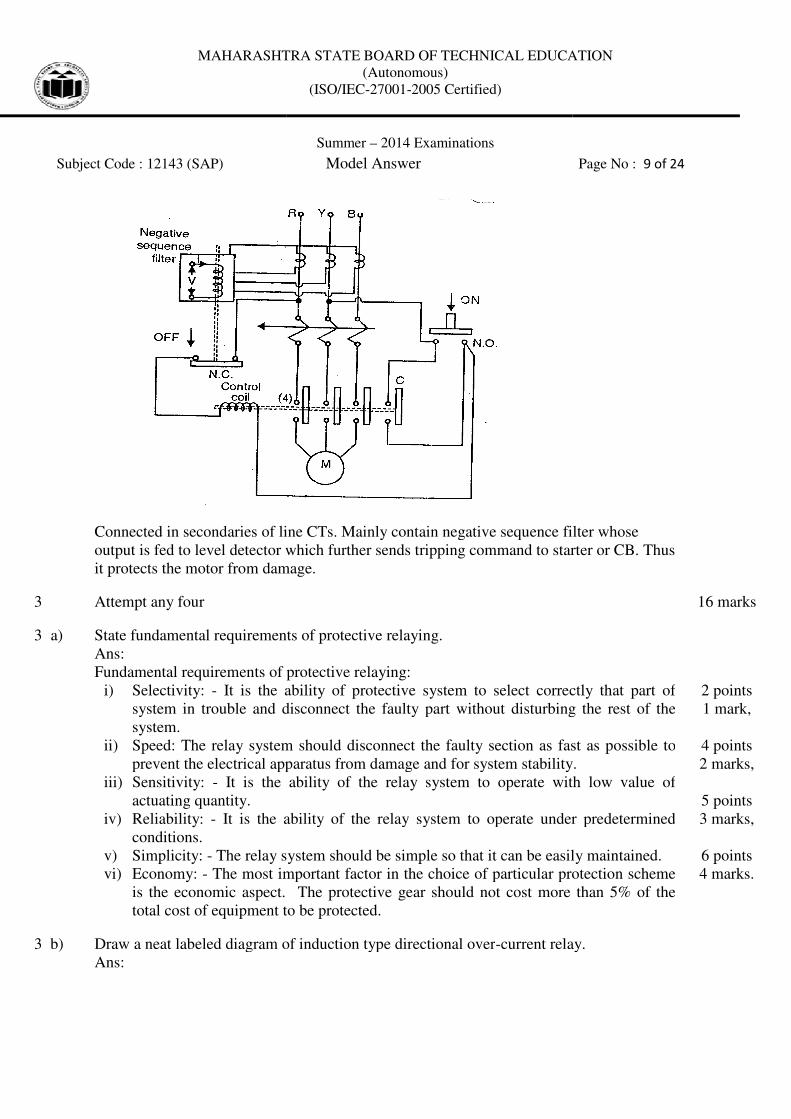
2 f) Draw a neat labeled diagram of single phasing preventer used for motor protection.
Ans:
Single phasing preventor:
MAHARASHTRA STATE BOARD OF TECHNICAL EDUCATION
(Autonomous)
(ISO/IEC-27001-2005 Certified)
Summer – 2014 Examinations
Subject Code : 12143 (SAP) Model Answer Page No :
State any four frequently occurring faults in 3 phase IM and suggest forms of protection
conditions due to external conditions:
Unbalanced supply voltages: protected by voltage summation scheme wherein the
three line voltages are summed to give a resultant voltage or output to trip the
motor control circuit or negative phase sequence currents are sensed in the case of
unbalance supply to give the trip signal.
protected by the hold on coil which releases/opens the main closed
power contacts if the voltage falls below a set threshold.
Reverse phase sequence starting: protection: in the case of reverse phase sequence
supply the motor control circuit does not energize till proper phase sequence is
restored thus motor is protected.
protected by single phasing preventer which prevents energizing
l all the phases are healthy restored.
Faults / abnormal conditions due to internal faults/conditions:
Bearing failures: stalling protection by bimetallic thermal relay.
it is detected by measuring element whose pickup value is set
potentiometer or similar device.
overload relays (normally bimetallic thermal relays) are used
proper fuses may be used for small motors.
for large motors embedded semiconductor resistance
temperature detectors are used to sense and trip the supply.
Blocked rotor / prolonged starting: similar to stalling condition, protection by
bimetallic thermal relay.
Heavy Short circuited winding or severe earth fault: detected / protected by fuse of
Draw a neat labeled diagram of single phasing preventer used for motor protection.
MAHARASHTRA STATE BOARD OF TECHNICAL EDUCATION
Page No : 8 of 24
State any four frequently occurring faults in 3 phase IM and suggest forms of protection
protected by voltage summation scheme wherein the
three line voltages are summed to give a resultant voltage or output to trip the
are sensed in the case of
protected by the hold on coil which releases/opens the main closed
in the case of reverse phase sequence
oper phase sequence is
protected by single phasing preventer which prevents energizing
stalling protection by bimetallic thermal relay.
it is detected by measuring element whose pickup value is set on
overload relays (normally bimetallic thermal relays) are used, also
for large motors embedded semiconductor resistance
similar to stalling condition, protection by
Heavy Short circuited winding or severe earth fault: detected / protected by fuse of
1 mark
each any
four = 4
marks
(1/2 mark
for fault
and ½
mark for
protection
other
valid
points
may be
considere
d if
relevant.
Draw a neat labeled diagram of single phasing preventer used for motor protection.
Labeled
diagram 4
marks
Partially
labeled 2
to 3
marks
Unlabeled
1 mark
MAHARASHTRA STATE BOARD OF TECHNICAL EDUCATION
Subject Code : 12143 (SAP)
Connected in secondaries of line CTs. Mainly contain negative sequence filter whose
output is fed to level detector which further sends tripping command to starter or CB. Thus
it protects the motor from damage.
3 Attempt any four
3 a) State fundamental requirements of protective relaying.
Ans:
Fundamental requirements of protective relaying:
i) Selectivity: - It is the ability of protective system to select correctly that part of
system in trouble and disconnect the faulty part without disturbing the rest
system.
ii) Speed: The relay system should disconnect the faulty section as fast as possible to
prevent the electrical apparatus from damage and for system stability.
iii) Sensitivity: - It is the ability of the relay system to operate with low value of
actuating quantity.
iv) Reliability: - It is the ability of the relay system to operate under predetermined
conditions.
v) Simplicity: - The relay system should be simple so that it can be easily maintained.
vi) Economy: - The most important factor in the choice of p
is the economic aspect. The protective gear should not cost more than 5% of the
total cost of equipment to be protected.
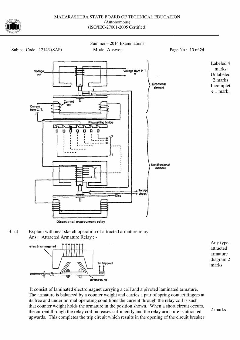
3 b) Draw a neat labeled diagram of induction type directional over
Ans:
MAHARASHTRA STATE BOARD OF TECHNICAL EDUCATION
(Autonomous)
(ISO/IEC-27001-2005 Certified)
Summer – 2014 Examinations
Subject Code : 12143 (SAP) Model Answer
econdaries of line CTs. Mainly contain negative sequence filter whose
output is fed to level detector which further sends tripping command to starter or CB. Thus
it protects the motor from damage.
requirements of protective relaying.
Fundamental requirements of protective relaying:
It is the ability of protective system to select correctly that part of
system in trouble and disconnect the faulty part without disturbing the rest
Speed: The relay system should disconnect the faulty section as fast as possible to
prevent the electrical apparatus from damage and for system stability.
It is the ability of the relay system to operate with low value of
It is the ability of the relay system to operate under predetermined
The relay system should be simple so that it can be easily maintained.
The most important factor in the choice of particular protection scheme
is the economic aspect. The protective gear should not cost more than 5% of the
total cost of equipment to be protected.
d diagram of induction type directional over-current relay.
MAHARASHTRA STATE BOARD OF TECHNICAL EDUCATION
Page No : 9 of 24
econdaries of line CTs. Mainly contain negative sequence filter whose
output is fed to level detector which further sends tripping command to starter or CB. Thus
16 marks
It is the ability of protective system to select correctly that part of
system in trouble and disconnect the faulty part without disturbing the rest of the
Speed: The relay system should disconnect the faulty section as fast as possible to
prevent the electrical apparatus from damage and for system stability.
It is the ability of the relay system to operate with low value of
It is the ability of the relay system to operate under predetermined
The relay system should be simple so that it can be easily maintained.
articular protection scheme
is the economic aspect. The protective gear should not cost more than 5% of the
2 points
1 mark,
4 points
2 marks,
5 points
3 marks,
6 points
4 marks.
current relay.
MAHARASHTRA STATE BOARD OF TECHNICAL EDUCATION
Subject Code : 12143 (SAP)
3 c) Explain with neat sketch operation of attracted armature relay.
Ans: Attracted Armature Relay :
It consist of laminated electromagnet carrying a coil and a pivoted laminated armature.
The armature is balanced by a counter weight and carries a pair of spring contact fingers at
its free and under normal operating conditions the current through the relay coil is such
that counter weight holds the armature in the position shown. When a short circuit occurs,
the current through the relay coil increases sufficiently and the relay armature is attracted
upwards. This completes the trip circuit which results in the opening of th
MAHARASHTRA STATE BOARD OF TECHNICAL EDUCATION
(Autonomous)
(ISO/IEC-27001-2005 Certified)
Summer – 2014 Examinations
Subject Code : 12143 (SAP) Model Answer Page No :
Explain with neat sketch operation of attracted armature relay.
Attracted Armature Relay : -
d electromagnet carrying a coil and a pivoted laminated armature.
The armature is balanced by a counter weight and carries a pair of spring contact fingers at
its free and under normal operating conditions the current through the relay coil is such
ounter weight holds the armature in the position shown. When a short circuit occurs,
the current through the relay coil increases sufficiently and the relay armature is attracted
upwards. This completes the trip circuit which results in the opening of the circuit
MAHARASHTRA STATE BOARD OF TECHNICAL EDUCATION
Page No : 10 of 24
Labeled 4
marks
Unlabeled
2 marks
Incomplet
e 1 mark.
d electromagnet carrying a coil and a pivoted laminated armature.
The armature is balanced by a counter weight and carries a pair of spring contact fingers at
its free and under normal operating conditions the current through the relay coil is such
ounter weight holds the armature in the position shown. When a short circuit occurs,
the current through the relay coil increases sufficiently and the relay armature is attracted
e circuit breaker
Any type
attracted
armature
diagram 2
marks
2 marks
MAHARASHTRA STATE BOARD OF TECHNICAL EDUCATION
Subject Code : 12143 (SAP)
3 d) Define following terms related to CT.
i) CT burden: it is the load imposed on the secondary of the
measured in VA (product of volts and amps).
ii) Ratio error: Ratio error : It is the ratio of error in the secondary side current w.r.t.
primary side given by [(N.I
currents, N = current ratio}
iii) Accuracy class: The class assigned to the C.T. with the
and phase angle error.
iv) Phase Angle error: It is the phase angle between primary current vector and the
reversed secondary current vector.
3 e) State functions of substation earthing system. Also s
earthing system.
Ans:
Functions:
i) Provide sufficiently low earth electrode resistance to ensure reliable operation of the
switchgear under fault/abnormal conditions.
ii) Provide means to carry and dissipate electric current i
abnormal conditions of working.
iii) Minimize arcing grounds.
iv) Provide degree of safety to personnel working/walking around the earthed
equipment of the substation.
v) Carry the maximum earth fault currents to avoid overheating, mechanica
unduly drying of soil around substation.
vi) Provide protection such that non
sheaths, armouring etc. do not suffer heavy
vii) Avoid dangerous potential areas in substation vicinity.
Parts of substation earthing systems:
i) Earth mats (mesh of steel strips or rods).
ii) Copper strips. Bars.
iii) Overhead earth/shield
iv) Earthing transformers.
v) Earthing switches.
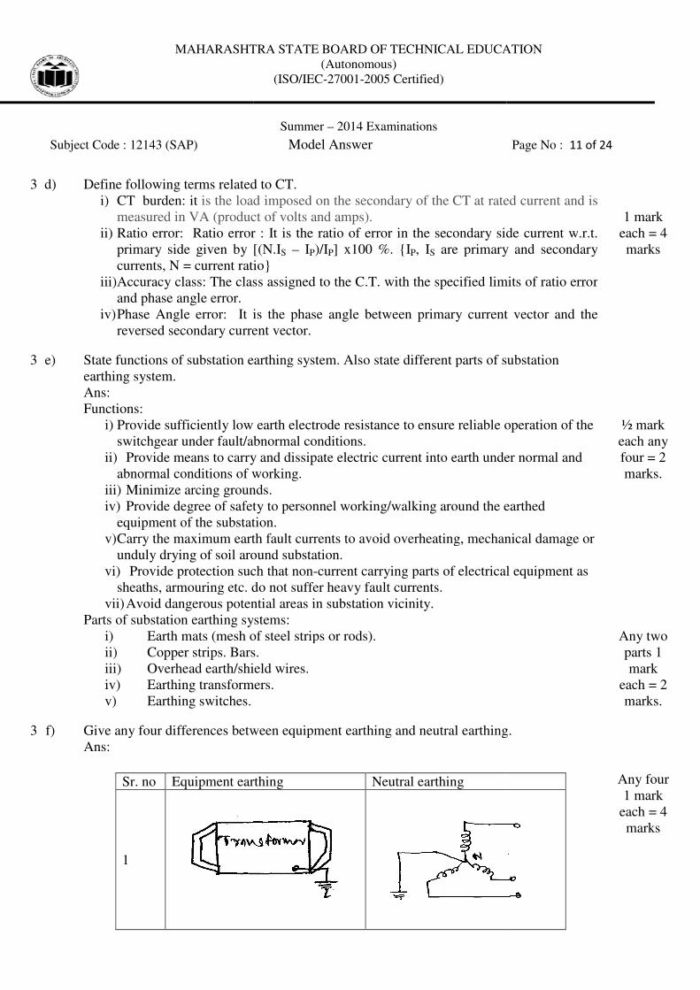
3 f) Give any four differences between equipment earthing and neutral earthing.
Ans:
Sr. no Equipment earthing
1
MAHARASHTRA STATE BOARD OF TECHNICAL EDUCATION
(Autonomous)
(ISO/IEC-27001-2005 Certified)
Summer – 2014 Examinations
Subject Code : 12143 (SAP) Model Answer
Define following terms related to CT.
is the load imposed on the secondary of the CT at rated current and is
measured in VA (product of volts and amps).
Ratio error: Ratio error : It is the ratio of error in the secondary side current w.r.t.
given by [(N.IS – IP)/IP] x100 %. {IP, IS are primary and secondary
currents, N = current ratio}
Accuracy class: The class assigned to the C.T. with the specified limits of ratio error
Phase Angle error: It is the phase angle between primary current vector and the
reversed secondary current vector.
State functions of substation earthing system. Also state different parts of substation
Provide sufficiently low earth electrode resistance to ensure reliable operation of the
switchgear under fault/abnormal conditions.
Provide means to carry and dissipate electric current into earth under normal and
abnormal conditions of working.
Minimize arcing grounds.
Provide degree of safety to personnel working/walking around the earthed
equipment of the substation.
maximum earth fault currents to avoid overheating, mechanica
unduly drying of soil around substation.
Provide protection such that non-current carrying parts of electrical equipment as
sheaths, armouring etc. do not suffer heavy fault currents.
Avoid dangerous potential areas in substation vicinity.
ts of substation earthing systems:
Earth mats (mesh of steel strips or rods).
Copper strips. Bars.
Overhead earth/shield wires.
Earthing transformers.
Give any four differences between equipment earthing and neutral earthing.
Equipment earthing Neutral earthing
MAHARASHTRA STATE BOARD OF TECHNICAL EDUCATION
Page No : 11 of 24
at rated current and is
Ratio error: Ratio error : It is the ratio of error in the secondary side current w.r.t.
are primary and secondary
specified limits of ratio error
Phase Angle error: It is the phase angle between primary current vector and the
1 mark
each = 4
marks
tate different parts of substation
Provide sufficiently low earth electrode resistance to ensure reliable operation of the
nto earth under normal and
Provide degree of safety to personnel working/walking around the earthed
maximum earth fault currents to avoid overheating, mechanical damage or
current carrying parts of electrical equipment as
½ mark
each any
four = 2
marks.
Any two
parts 1
mark
each = 2
marks.
Give any four differences between equipment earthing and neutral earthing.
Any four
1 mark
each = 4
marks
MAHARASHTRA STATE BOARD OF TECHNICAL EDUCATION
Subject Code : 12143 (SAP)
2
Connection of
carrying metallic part
electrical equipment
called as equipment earthing.
3
It is provided for protection of
human being from electric
shocks.
4 It has nothing to do with
stability
5
Equipment earthing is provided
through Pipe earthing, Plate
earthing.
6
It does not provide any means
for protection system against
earth fault
4 a) Attempt any three of the following:
4 a) i) Define short circuit. Discuss possible causes of
Ans:
Definition: whenever the charged (live) conductor/line/lines of an electric supply path
make contact with a line/conductor/path of different potential to circulate heavy
heavy currents due to the unintended
occur between phases, phase/s and neutral or phase/s and earth.
Possible causes of short circuit in power station:
1) Failure of insulation between lines or lines and earth
(equipment body included) due to following reasons:
i) Deteriorated insulation due to aging.
ii) Voltage surge due to external causes as lightning, switching of external
devices.
iii) Voltage surge due to internal causes as switching of devices.
iv) Bad very humid atmos
2) Generator bus terminals insulation
3) Transformer bus terminals
4) Sustained equipment overloading leading to overheating and finally failure o
insulation.
5) Improper maintenance of power station equipment.
4 a) ii)
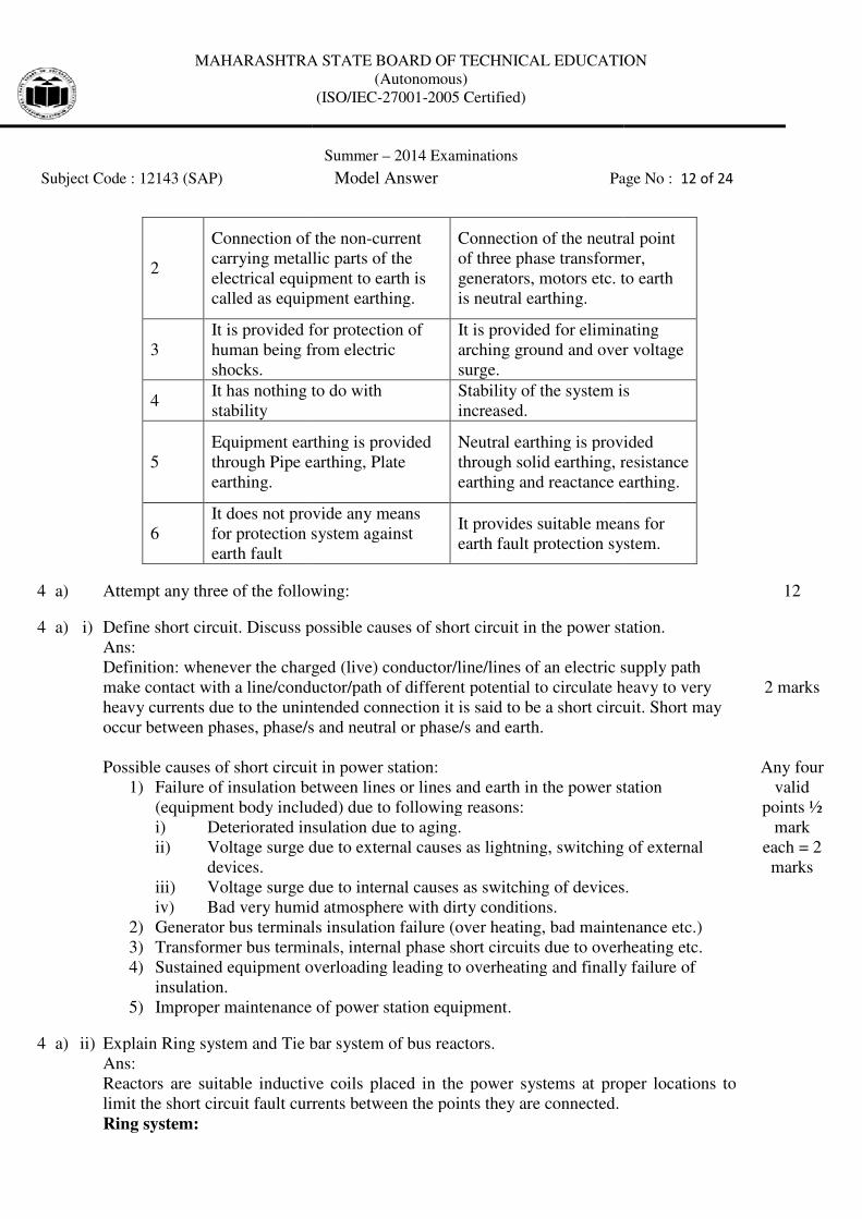
Explain Ring system and Tie bar system of bus reactors.
Ans:
Reactors are suitable inductive coils placed in the power
limit the short circuit fault currents between the points they are connected.
Ring system:
MAHARASHTRA STATE BOARD OF TECHNICAL EDUCATION
(Autonomous)
(ISO/IEC-27001-2005 Certified)
Summer – 2014 Examinations
Subject Code : 12143 (SAP) Model Answer Page No :
Connection of the non-current
carrying metallic parts of the
electrical equipment to earth is
s equipment earthing.
Connection of the neutral
of three phase transformer,
generators, motors etc. to earth
is neutral earthing.
It is provided for protection of
human being from electric
It is provided for eliminating
arching ground and over voltage
surge.
It has nothing to do with Stability of the system is
increased.
Equipment earthing is provided
through Pipe earthing, Plate
Neutral earthing is provided
through solid earthing, r
earthing and reactance earthing.
It does not provide any means
for protection system against It provides suitable means for
earth fault protection system.
Attempt any three of the following:
Define short circuit. Discuss possible causes of short circuit in the power station.
Definition: whenever the charged (live) conductor/line/lines of an electric supply path
make contact with a line/conductor/path of different potential to circulate heavy
due to the unintended connection it is said to be a short circuit. Short may
occur between phases, phase/s and neutral or phase/s and earth.
Possible causes of short circuit in power station:
Failure of insulation between lines or lines and earth in the power station
nt body included) due to following reasons:
Deteriorated insulation due to aging.
Voltage surge due to external causes as lightning, switching of external
Voltage surge due to internal causes as switching of devices.
Bad very humid atmosphere with dirty conditions.
Generator bus terminals insulation failure (over heating, bad maintenance etc.)
Transformer bus terminals, internal phase short circuits due to overheating etc.
Sustained equipment overloading leading to overheating and finally failure o
Improper maintenance of power station equipment.
Explain Ring system and Tie bar system of bus reactors.
Reactors are suitable inductive coils placed in the power systems at proper locations to
limit the short circuit fault currents between the points they are connected.
MAHARASHTRA STATE BOARD OF TECHNICAL EDUCATION
Page No : 12 of 24
neutral point
transformer,
etc. to earth
It is provided for eliminating
over voltage
Stability of the system is
Neutral earthing is provided
resistance
earthing.
It provides suitable means for
earth fault protection system.
12
short circuit in the power station.
Definition: whenever the charged (live) conductor/line/lines of an electric supply path
make contact with a line/conductor/path of different potential to circulate heavy to very
it is said to be a short circuit. Short may
in the power station
Voltage surge due to external causes as lightning, switching of external
Voltage surge due to internal causes as switching of devices.
, bad maintenance etc.)
, internal phase short circuits due to overheating etc.
Sustained equipment overloading leading to overheating and finally failure of
2 marks
Any four
valid
points ½
mark
each = 2
marks
systems at proper locations to
MAHARASHTRA STATE BOARD OF TECHNICAL EDUCATION
Subject Code : 12143 (SAP)
Each feeder is mostly fed by a single generator. The reactors have high reactances such
that the generator busbars are nearly
little voltage across them. Under fault on one of the feeders it is mainly fed by the
respective generator. The other generators feed the faulty feeder through the reactors
which limit the fault current.
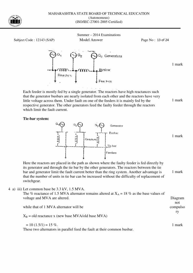
Tie-bar system:
Here the reactors are placed in the path as shown where the faulty feeder is fed directly by
its generator and through the tie bar by the other generators. The reactors between the tie
bar and generator limit the fault current better than the
that the number of units in tie bar can be i
switchgear.
4 a) iii) Let common base be 3.3 kV, 1.5 MVA.
The % reactance of 1.5 MVA alternator remains altered at X
voltage and MVA are altered.
while that of 1 MVA alternator will be
XB = old reactance x (new base MVA/old base MVA)
= 10 (1.5/1) = 15 %.
These two alternators in paralle
MAHARASHTRA STATE BOARD OF TECHNICAL EDUCATION
(Autonomous)
(ISO/IEC-27001-2005 Certified)
Summer – 2014 Examinations
Subject Code : 12143 (SAP) Model Answer
Each feeder is mostly fed by a single generator. The reactors have high reactances such
that the generator busbars are nearly isolated from each other and the reactors have very
little voltage across them. Under fault on one of the feeders it is mainly fed by the
respective generator. The other generators feed the faulty feeder through the reactors
Here the reactors are placed in the path as shown where the faulty feeder is fed directly by
its generator and through the tie bar by the other generators. The reactors between the tie
bar and generator limit the fault current better than the ring system. Another advantage is
that the number of units in tie bar can be increased without the difficulty of replacement of
Let common base be 3.3 kV, 1.5 MVA.
tance of 1.5 MVA alternator remains altered at XA = 18 % as the base values of
while that of 1 MVA alternator will be
= old reactance x (new base MVA/old base MVA)
These two alternators in parallel feed the fault at their common busbar.
MAHARASHTRA STATE BOARD OF TECHNICAL EDUCATION
Page No : 13 of 24
Each feeder is mostly fed by a single generator. The reactors have high reactances such
ted from each other and the reactors have very
little voltage across them. Under fault on one of the feeders it is mainly fed by the
respective generator. The other generators feed the faulty feeder through the reactors
Here the reactors are placed in the path as shown where the faulty feeder is fed directly by
its generator and through the tie bar by the other generators. The reactors between the tie
ring system. Another advantage is
ncreased without the difficulty of replacement of
1 mark
1 mark
1 mark
1 mark
= 18 % as the base values of
Diagram
not
compulso
ry
1 mark
MAHARASHTRA STATE BOARD OF TECHNICAL EDUCATION
Subject Code : 12143 (SAP)
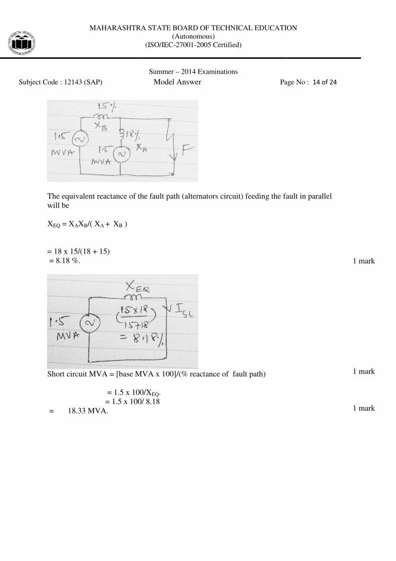
The equivalent reactance of the fault path (alternators circuit) feeding the fault in parallel
will be
XEQ = XAXB/( XA + XB )
= 18 x 15/(18 + 15)
= 8.18 %.
Short circuit MVA = [base MVA x 100]/(% reactance of fault path)
= 1.5 x 100/X
= 1.5 x 100/ 8.18
= 18.33 MVA.
MAHARASHTRA STATE BOARD OF TECHNICAL EDUCATION
(Autonomous)
(ISO/IEC-27001-2005 Certified)
Summer – 2014 Examinations
Subject Code : 12143 (SAP) Model Answer Page No :
The equivalent reactance of the fault path (alternators circuit) feeding the fault in parallel
cuit MVA = [base MVA x 100]/(% reactance of fault path)
= 1.5 x 100/XEQ.
= 1.5 x 100/ 8.18
MAHARASHTRA STATE BOARD OF TECHNICAL EDUCATION
Page No : 14 of 24
The equivalent reactance of the fault path (alternators circuit) feeding the fault in parallel
1 mark
1 mark
1 mark
MAHARASHTRA STATE BOARD OF TECHNICAL EDUCATION
Subject Code : 12143 (SAP)
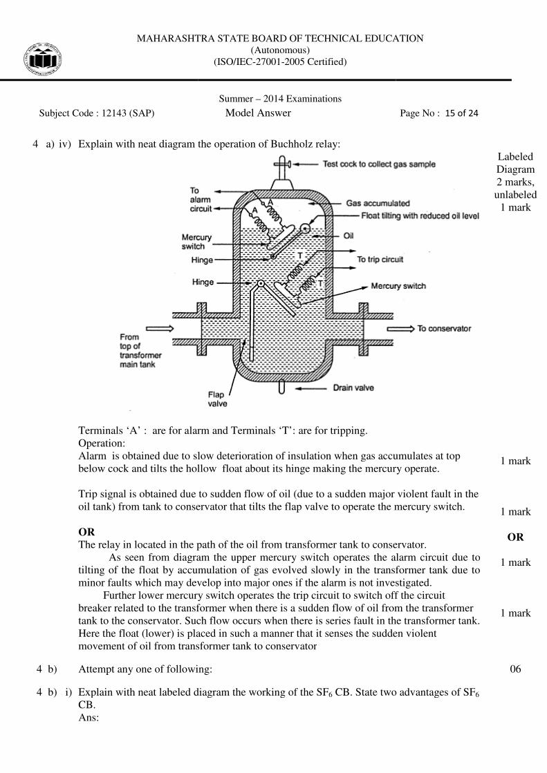
4 a) iv) Explain with neat diagram the operation of Buchholz relay:
Terminals ‘A’ : are for alarm and Terminals ‘T’: are for
Operation:
Alarm is obtained due to slow deterioration of insulation when gas accumulates at top
below cock and tilts the hollow float about its hinge making the mercury operate.
Trip signal is obtained due to sudden flow of oil (due to a sudden major violent fault in the
oil tank) from tank to conservator that tilts the flap valve to operate the mercury switch.
OR
The relay in located in the path of the oil from transformer tank to conservator.
As seen from diagram the upper mercury switch operates the alarm circuit due to
tilting of the float by accumulation of gas evolved slowly in the transformer
minor faults which may develop into major ones if the alarm is not investigated.
Further lower mercury switch operates the trip circuit to switch off the circuit
breaker related to the transformer when there is a sudden flow of oil fr
tank to the conservator. Such flow occurs when there is series fault in the transformer tank.
Here the float (lower) is placed in such a manner that it senses the sudden violent
movement of oil from transformer tank to conservator
4 b) Attempt any one of following:
4 b) i) Explain with neat labeled diagram the working of the SF
CB.
Ans:
MAHARASHTRA STATE BOARD OF TECHNICAL EDUCATION
(Autonomous)
(ISO/IEC-27001-2005 Certified)
Summer – 2014 Examinations
Subject Code : 12143 (SAP) Model Answer
Explain with neat diagram the operation of Buchholz relay:
are for alarm and Terminals ‘T’: are for tripping.
Alarm is obtained due to slow deterioration of insulation when gas accumulates at top
d tilts the hollow float about its hinge making the mercury operate.
Trip signal is obtained due to sudden flow of oil (due to a sudden major violent fault in the
oil tank) from tank to conservator that tilts the flap valve to operate the mercury switch.
The relay in located in the path of the oil from transformer tank to conservator.
As seen from diagram the upper mercury switch operates the alarm circuit due to
tilting of the float by accumulation of gas evolved slowly in the transformer
minor faults which may develop into major ones if the alarm is not investigated.
Further lower mercury switch operates the trip circuit to switch off the circuit
breaker related to the transformer when there is a sudden flow of oil from the transformer
tank to the conservator. Such flow occurs when there is series fault in the transformer tank.
Here the float (lower) is placed in such a manner that it senses the sudden violent
movement of oil from transformer tank to conservator
Attempt any one of following:
Explain with neat labeled diagram the working of the SF6 CB. State two advantages of SF
MAHARASHTRA STATE BOARD OF TECHNICAL EDUCATION
Page No : 15 of 24
Alarm is obtained due to slow deterioration of insulation when gas accumulates at top
d tilts the hollow float about its hinge making the mercury operate.
Trip signal is obtained due to sudden flow of oil (due to a sudden major violent fault in the
oil tank) from tank to conservator that tilts the flap valve to operate the mercury switch.
The relay in located in the path of the oil from transformer tank to conservator.
As seen from diagram the upper mercury switch operates the alarm circuit due to
tilting of the float by accumulation of gas evolved slowly in the transformer tank due to
minor faults which may develop into major ones if the alarm is not investigated.
Further lower mercury switch operates the trip circuit to switch off the circuit
om the transformer
tank to the conservator. Such flow occurs when there is series fault in the transformer tank.
Here the float (lower) is placed in such a manner that it senses the sudden violent
Labeled
Diagram
2 marks,
unlabeled
1 mark
1 mark
1 mark
OR
1 mark
1 mark
06
CB. State two advantages of SF6
MAHARASHTRA STATE BOARD OF TECHNICAL EDUCATION
Subject Code : 12143 (SAP)
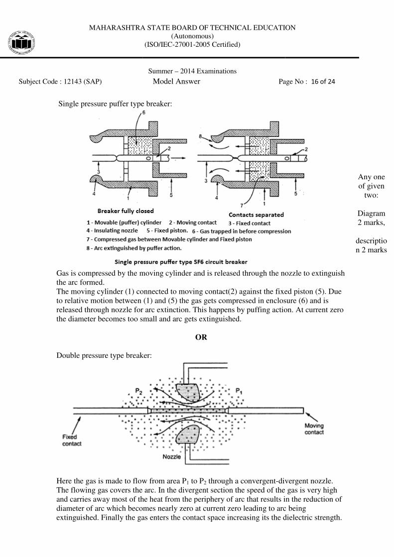
Single pressure puffer type br
Gas is compressed by the moving cylinder and is released through the nozzle to extinguish
the arc formed.
The moving cylinder (1) connected to moving contact(2) against the fixed piston (5). Due
to relative motion between
released through nozzle for arc extinction. This happens by puffing action. At current zero
the diameter becomes too small and arc gets extinguished.
Double pressure type breaker:
Here the gas is made to flow from
The flowing gas covers the arc. In the divergent section the speed of the gas is very high
and carries away most of the heat from the periphery of arc that results in the reduction of
diameter of arc which becomes nearly zero at current zero leading to arc being
extinguished. Finally the gas enters the contact space increasing its the dielectric strength.
MAHARASHTRA STATE BOARD OF TECHNICAL EDUCATION
(Autonomous)
(ISO/IEC-27001-2005 Certified)
Summer – 2014 Examinations
Subject Code : 12143 (SAP) Model Answer Page No :
Single pressure puffer type breaker:
Gas is compressed by the moving cylinder and is released through the nozzle to extinguish
The moving cylinder (1) connected to moving contact(2) against the fixed piston (5). Due
to relative motion between (1) and (5) the gas gets compressed in enclosure (6) and is
released through nozzle for arc extinction. This happens by puffing action. At current zero
the diameter becomes too small and arc gets extinguished.
OR
Double pressure type breaker:
Here the gas is made to flow from area P1 to P2 through a convergent-divergent
The flowing gas covers the arc. In the divergent section the speed of the gas is very high
and carries away most of the heat from the periphery of arc that results in the reduction of
ich becomes nearly zero at current zero leading to arc being
as enters the contact space increasing its the dielectric strength.
MAHARASHTRA STATE BOARD OF TECHNICAL EDUCATION
Page No : 16 of 24
Gas is compressed by the moving cylinder and is released through the nozzle to extinguish
The moving cylinder (1) connected to moving contact(2) against the fixed piston (5). Due
compressed in enclosure (6) and is
released through nozzle for arc extinction. This happens by puffing action. At current zero
divergent nozzle.
The flowing gas covers the arc. In the divergent section the speed of the gas is very high
and carries away most of the heat from the periphery of arc that results in the reduction of
ich becomes nearly zero at current zero leading to arc being
as enters the contact space increasing its the dielectric strength.
Any one
of given
two:
Diagram
2 marks,
descriptio
n 2 marks
MAHARASHTRA STATE BOARD OF TECHNICAL EDUCATION
Subject Code : 12143 (SAP)
Advantages of SF6 breaker:
1. Higher speed interruption
2. Long arc length not needed for arc interruptio
3. Lower arcing time.
4. No frequent contact maintenance.
5. Cleaner operation.
6. Cleaner maintenance as it is less bulky and cleaner than oil
4 b) ii) Distance Relay –
Principle: The action of relay depends u
where the relay is installed and the point of fault.
of voltage and current in the fault path.
certain value. Higher current indic
Types --
1) Impedance relay
2) Mho relay
3) Reactance relay
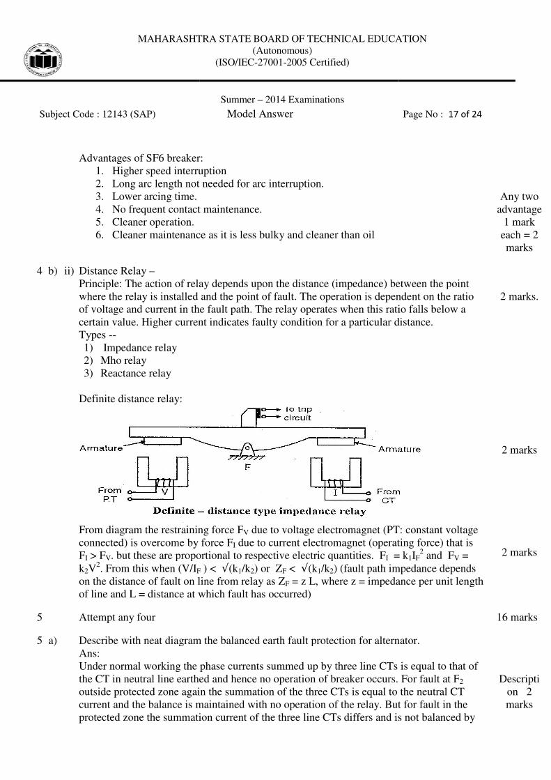
Definite distance relay:
From diagram the restraining force F
connected) is overcome by force F
FI > FV. but these are proportional to respective electric quantities. F
k2V2. From this when (V/IF
on the distance of fault on line from relay as Z
of line and L = distance at which fault has occurred)
5 Attempt any four
5 a) Describe with neat diagram the balanced earth fault protection for alternator.
Ans:
Under normal working the phase currents summed up by three line CTs is equal to that of
the CT in neutral line earthed and hence no operation of breaker occurs. For fault at F
outside protected zone again the summation of the three CTs is equal to the neutral CT
current and the balance is maintained with no operation of the relay. But for fault in
protected zone the summation current of the three line CTs differs and is not balanced by
MAHARASHTRA STATE BOARD OF TECHNICAL EDUCATION
(Autonomous)
(ISO/IEC-27001-2005 Certified)
Summer – 2014 Examinations
Subject Code : 12143 (SAP) Model Answer
Advantages of SF6 breaker:
Higher speed interruption
Long arc length not needed for arc interruption.
No frequent contact maintenance.
maintenance as it is less bulky and cleaner than oil
The action of relay depends upon the distance (impedance) between the point
where the relay is installed and the point of fault. The operation is dependent on the ratio
in the fault path. The relay operates when this ratio falls below a
certain value. Higher current indicates faulty condition for a particular distance.
iagram the restraining force FV due to voltage electromagnet (PT: constant voltage
connected) is overcome by force FI due to current electromagnet (operating force) that is
. but these are proportional to respective electric quantities. FI = k
F ) < √(k1/k2) or ZF < √(k1/k2) (fault path impedance depends
on the distance of fault on line from relay as ZF = z L, where z = impedance per unit length
of line and L = distance at which fault has occurred)
Describe with neat diagram the balanced earth fault protection for alternator.
Under normal working the phase currents summed up by three line CTs is equal to that of
in neutral line earthed and hence no operation of breaker occurs. For fault at F
outside protected zone again the summation of the three CTs is equal to the neutral CT
current and the balance is maintained with no operation of the relay. But for fault in
protected zone the summation current of the three line CTs differs and is not balanced by
MAHARASHTRA STATE BOARD OF TECHNICAL EDUCATION
Page No : 17 of 24
Any two
advantage
1 mark
each = 2
marks
) between the point
The operation is dependent on the ratio
The relay operates when this ratio falls below a
ates faulty condition for a particular distance.
due to voltage electromagnet (PT: constant voltage
due to current electromagnet (operating force) that is
= k1IF2 and FV =
) (fault path impedance depends
= z L, where z = impedance per unit length
2 marks.
2 marks
2 marks
16 marks
Describe with neat diagram the balanced earth fault protection for alternator.
Under normal working the phase currents summed up by three line CTs is equal to that of
in neutral line earthed and hence no operation of breaker occurs. For fault at F2
outside protected zone again the summation of the three CTs is equal to the neutral CT
current and the balance is maintained with no operation of the relay. But for fault in the
protected zone the summation current of the three line CTs differs and is not balanced by
Descripti
on 2
marks
MAHARASHTRA STATE BOARD OF TECHNICAL EDUCATION
Subject Code : 12143 (SAP)
the earthed neutral line CT current and the unbalance current in the relay operates it to trip
the breaker related and protect form the earth fault.
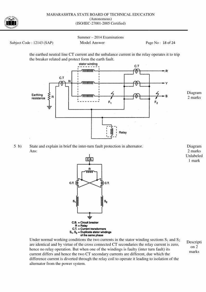
5 b) State and explain in brief the inter
Ans:
Under normal working conditions the two currents in the stator winding sections S
are identical and by virtue of the cross connected CT secondaries the relay current is zero,
hence no relay operation. But when one of the windings is faulty (inter turn fault) its
current differs and hence the two CT secondary currents are different, due which the
difference current is diverted through the relay coil to operate it leading to isolation of the
alternator from the power system.
MAHARASHTRA STATE BOARD OF TECHNICAL EDUCATION
(Autonomous)
(ISO/IEC-27001-2005 Certified)
Summer – 2014 Examinations
Subject Code : 12143 (SAP) Model Answer Page No :
the earthed neutral line CT current and the unbalance current in the relay operates it to trip
the breaker related and protect form the earth fault.
State and explain in brief the inter-turn fault protection in alternator.
Under normal working conditions the two currents in the stator winding sections S
y virtue of the cross connected CT secondaries the relay current is zero,
hence no relay operation. But when one of the windings is faulty (inter turn fault) its
current differs and hence the two CT secondary currents are different, due which the
e current is diverted through the relay coil to operate it leading to isolation of the
alternator from the power system.
MAHARASHTRA STATE BOARD OF TECHNICAL EDUCATION
Page No : 18 of 24
the earthed neutral line CT current and the unbalance current in the relay operates it to trip
Diagram
2 marks
Under normal working conditions the two currents in the stator winding sections S1 and S2
y virtue of the cross connected CT secondaries the relay current is zero,
hence no relay operation. But when one of the windings is faulty (inter turn fault) its
current differs and hence the two CT secondary currents are different, due which the
e current is diverted through the relay coil to operate it leading to isolation of the
Diagram
2 marks
Unlabeled
1 mark
Descripti
on 2
marks
MAHARASHTRA STATE BOARD OF TECHNICAL EDUCATION
Subject Code : 12143 (SAP)
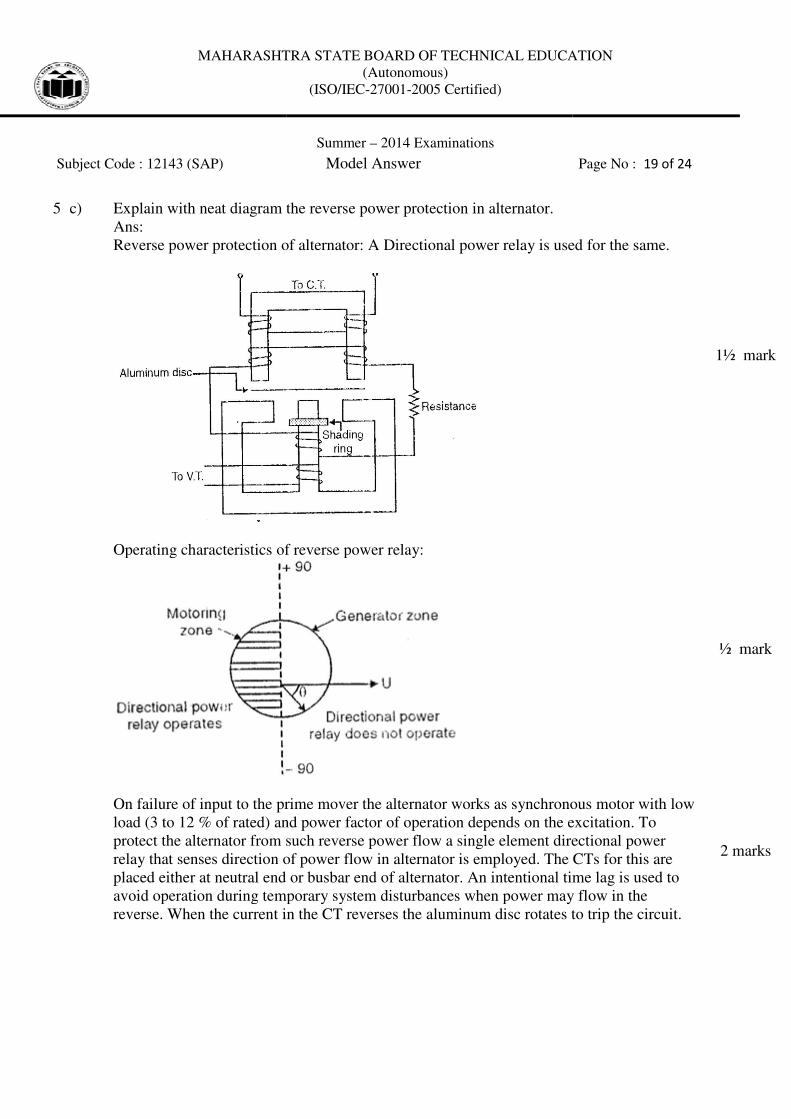
5 c) Explain with neat diagram the reverse power protection in
Ans:
Reverse power protection of alternator:
Operating characteristics of reverse power relay:
On failure of input to the prime mover the alternator works as sy
load (3 to 12 % of rated) and p
protect the alternator from such reverse power flow
relay that senses direction of power flow in alternator is employed. The CTs for this a
placed either at neutral end or busbar end of alternator. An intentional time lag is used to
avoid operation during temporary system disturbances when power may flow in the
reverse. When the current in the CT reverses the aluminum disc rotates to trip t
MAHARASHTRA STATE BOARD OF TECHNICAL EDUCATION
(Autonomous)
(ISO/IEC-27001-2005 Certified)
Summer – 2014 Examinations
Subject Code : 12143 (SAP) Model Answer
Explain with neat diagram the reverse power protection in alternator.
Reverse power protection of alternator: A Directional power relay is used for the same.
Operating characteristics of reverse power relay:
On failure of input to the prime mover the alternator works as synchronous motor with low
% of rated) and power factor of operation depends on the excitation. To
or from such reverse power flow a single element directional
relay that senses direction of power flow in alternator is employed. The CTs for this a
placed either at neutral end or busbar end of alternator. An intentional time lag is used to
avoid operation during temporary system disturbances when power may flow in the
When the current in the CT reverses the aluminum disc rotates to trip t
MAHARASHTRA STATE BOARD OF TECHNICAL EDUCATION
Page No : 19 of 24
A Directional power relay is used for the same.
nchronous motor with low
the excitation. To
directional power
relay that senses direction of power flow in alternator is employed. The CTs for this are
placed either at neutral end or busbar end of alternator. An intentional time lag is used to
avoid operation during temporary system disturbances when power may flow in the
When the current in the CT reverses the aluminum disc rotates to trip the circuit.
1½ mark
½ mark
2 marks
MAHARASHTRA STATE BOARD OF TECHNICAL EDUCATION
Subject Code : 12143 (SAP)
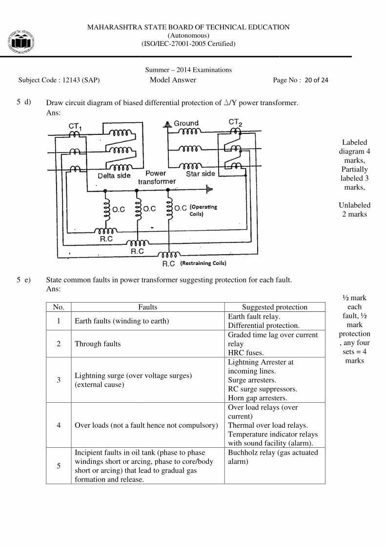
5 d) Draw circuit diagram of biased differential protection of
Ans:
5 e) State common faults in power transformer suggesting protection for each fault.
Ans:
No. Faults
1 Earth faults (winding to earth)
2 Through faults
3 Lightning surge (over voltage surges)
(external cause)
4 Over loads (not a fault hence not compulsory)
5
Incipient faults in oil tank (phase to phase
windings short or arcing, phase to core/body
short or arcing) that lead to gradual gas
formation and release.
MAHARASHTRA STATE BOARD OF TECHNICAL EDUCATION
(Autonomous)
(ISO/IEC-27001-2005 Certified)
Summer – 2014 Examinations
Subject Code : 12143 (SAP) Model Answer Page No :
Draw circuit diagram of biased differential protection of D/Y power transformer.
mon faults in power transformer suggesting protection for each fault.
Faults Suggested protection
Earth faults (winding to earth) Earth fault relay.
Differential protection.
Graded time lag over current
relay
HRC fuses.
ghtning surge (over voltage surges)
Lightning Arrester at
incoming lines.
Surge arresters.
RC surge suppressors.
Horn gap arresters.
Over loads (not a fault hence not compulsory)
Over load relays (over
current)
Thermal over load relays.
Temperature indicator relays
with sound facility (alarm).
Incipient faults in oil tank (phase to phase
windings short or arcing, phase to core/body
short or arcing) that lead to gradual gas
formation and release.
Buchholz relay (gas actuated
alarm)
MAHARASHTRA STATE BOARD OF TECHNICAL EDUCATION
Page No : 20 of 24
/Y power transformer.
Labeled
diagram 4
marks,
Partially
labeled 3
marks,
Unlabeled
2 marks
mon faults in power transformer suggesting protection for each fault.
Suggested protection
Earth fault relay.
Differential protection.
Graded time lag over current
Lightning Arrester at
RC surge suppressors.
Horn gap arresters.
Over load relays (over
Thermal over load relays.
Temperature indicator relays
with sound facility (alarm).
Buchholz relay (gas actuated
½ mark
each
fault, ½
mark
protection
, any four
sets = 4
marks
MAHARASHTRA STATE BOARD OF TECHNICAL EDUCATION
Subject Code : 12143 (SAP)
6
Sudden fault (mild explosion) in oil tank due
to faults between phase windings or to
earth/core/body leading to sudden flow of oil
towards conservator.
7 Sudden violent explosion in oil tank.
8 Magnetic core saturation
5 f) 66 kV/11 kV, star delta transformer,
Assume 250 A is flowing in lines on LT side.
(V1 & V2 are primary (HT) and secondary
and secondary (LT) line current
Primary kVA = secondary kVA,
√3 V1I1 = √3 V2I2
Hence I1 = I2(V2/V1) = 250 x 11/66 =
on HT.
On delta side (LT) the CT secondaries are star connected. Their secondary current is 5 A.
in pilot wires between HT and LT CTs.
On HT side (star connection of power transformer)
connected have currents = (5/√
Hence CT ratio on HT side is I
6 Attempt any four
6 a) State abnormalities and faults on busbars.
Ans:
Abnormalities and faults on busbars are:
1) Weakening and failure of insulation due to aging and
2) CB failure.
3) Earth fault due to failure of support insulator.
4) Flashover due to sustained excessive over vol
5) Errors/mistakes in operation and mainten
MAHARASHTRA STATE BOARD OF TECHNICAL EDUCATION
(Autonomous)
(ISO/IEC-27001-2005 Certified)
Summer – 2014 Examinations
Subject Code : 12143 (SAP) Model Answer
Sudden fault (mild explosion) in oil tank due
to faults between phase windings or to
earth/core/body leading to sudden flow of oil
Buchholz relay trip.
PRV at tank top
Sudden violent explosion in oil tank.
PRV (pressure release val
at top of tank that bursts out
to release the pressure by
spilling oil out.
Percentage differential
protection
Magnetic core saturation
Over voltage protection
Over fluxing protection
66 kV/11 kV, star delta transformer,
0 A is flowing in lines on LT side.
and secondary (LT) line voltages, I1 & I2 are primary
currents).
Primary kVA = secondary kVA,
) = 250 x 11/66 = (125/3) A = 41.66 A, which is primary CT current
the CT secondaries are star connected. Their secondary current is 5 A.
in pilot wires between HT and LT CTs.
star connection of power transformer) CT secondaries which are delta
√3) A in them.
Hence CT ratio on HT side is I1 : (5/√3) = (125/3) : (5/√3) = (25/√3) :1.
State abnormalities and faults on busbars.
s and faults on busbars are:
and failure of insulation due to aging and deterioration.
fault due to failure of support insulator.
due to sustained excessive over voltages.
mistakes in operation and maintenance of switchgear.
MAHARASHTRA STATE BOARD OF TECHNICAL EDUCATION
Page No : 21 of 24
Buchholz relay trip.
PRV (pressure release valve)
at top of tank that bursts out
to release the pressure by
Percentage differential
Over voltage protection
Over fluxing protection
are primary (HT)
, which is primary CT current
the CT secondaries are star connected. Their secondary current is 5 A.
CT secondaries which are delta
1 mark
1 mark
1 mark
1 mark
16 marks
½ mark
each any
eight = 4
marks
MAHARASHTRA STATE BOARD OF TECHNICAL EDUCATION
Subject Code : 12143 (SAP)
6) Mechanical damage due to improper working of personnel or earth quake.
7) Accidents due to other bodies falling
8) Flashover due to heavily polluted insulator.
9) Loosened fittings due to
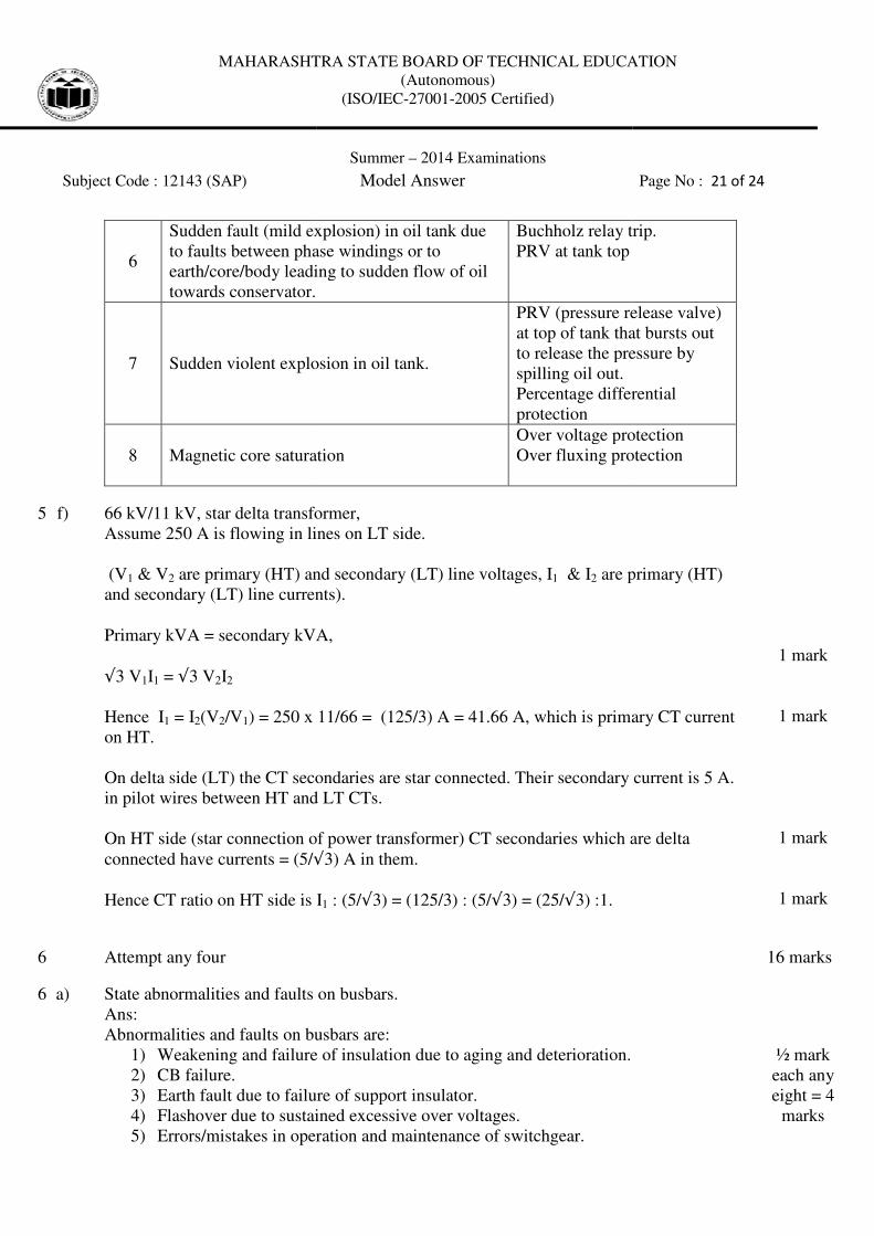
6 b) Describe fault bus protection with diagram for busbars.
Ans:
Fault bus protection for bus bars:
- Each phase bus is surrounded by an earthed metal mesh or structure
fault bus)
- Hence the busbar fault w
- The earth path current is sensed by the CT and if it is above the relay setting value
the relay trips the concerned circuit breaker indicating bus bar fault.
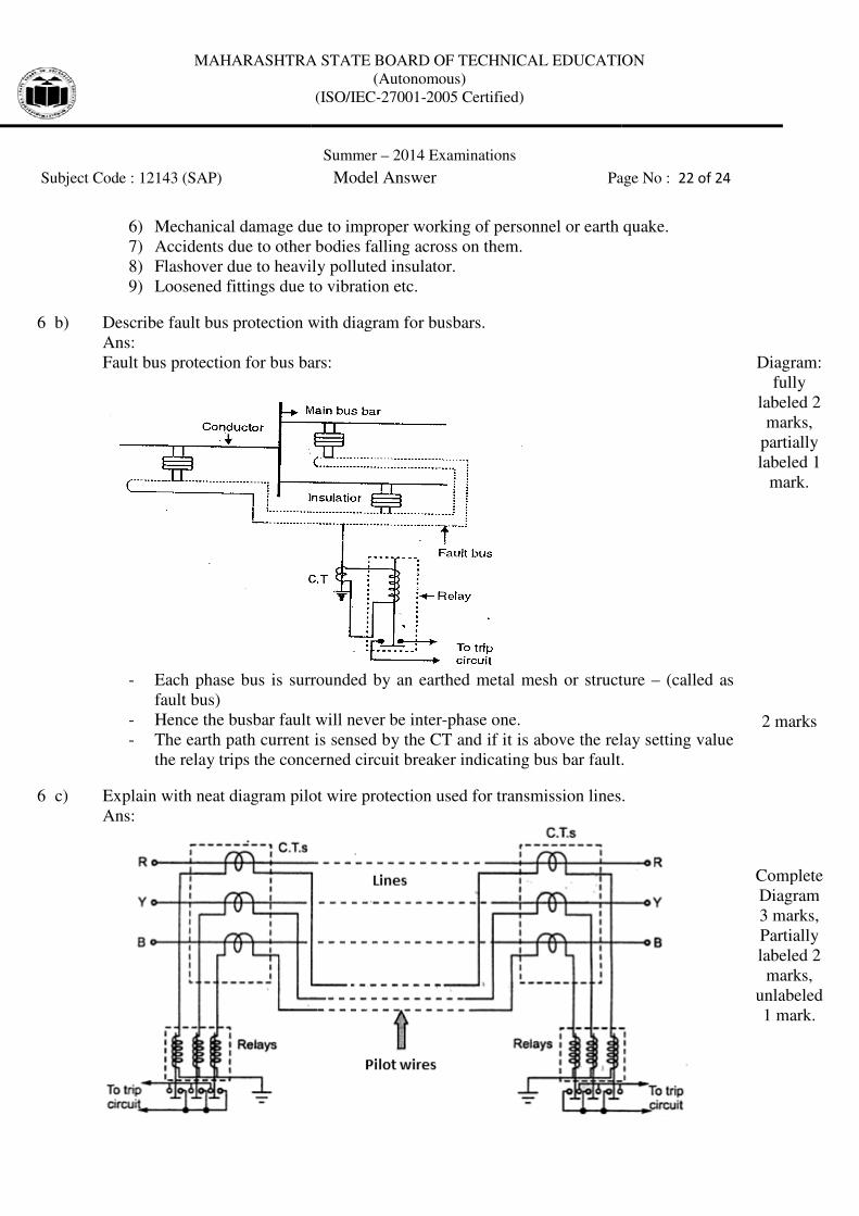
6 c) Explain with neat diagram pilot wire protection used for transmission lines.
Ans:
MAHARASHTRA STATE BOARD OF TECHNICAL EDUCATION
(Autonomous)
(ISO/IEC-27001-2005 Certified)
Summer – 2014 Examinations
Subject Code : 12143 (SAP) Model Answer Page No :
damage due to improper working of personnel or earth quake.
due to other bodies falling across on them.
due to heavily polluted insulator.
ned fittings due to vibration etc.
Describe fault bus protection with diagram for busbars.
Fault bus protection for bus bars:
Each phase bus is surrounded by an earthed metal mesh or structure
Hence the busbar fault will never be inter-phase one.
The earth path current is sensed by the CT and if it is above the relay setting value
the relay trips the concerned circuit breaker indicating bus bar fault.
ram pilot wire protection used for transmission lines.
MAHARASHTRA STATE BOARD OF TECHNICAL EDUCATION
Page No : 22 of 24
damage due to improper working of personnel or earth quake.
Each phase bus is surrounded by an earthed metal mesh or structure – (called as
The earth path current is sensed by the CT and if it is above the relay setting value
the relay trips the concerned circuit breaker indicating bus bar fault.
Diagram:
fully
labeled 2
marks,
partially
labeled 1
mark.
2 marks
ram pilot wire protection used for transmission lines.
Complete
Diagram
3 marks,
Partially
labeled 2
marks,
unlabeled
1 mark.
MAHARASHTRA STATE BOARD OF TECHNICAL EDUCATION
Subject Code : 12143 (SAP)
Current entering one end of lines is equal to that leaving from other end under healthy
condition. Hence CT secondar
hence no relay current. But if there is fault in between then the two side CTs have different
induced voltages resulting in current through relay coil
6 d) State various causes of over voltages
Ans:
Causes of over voltages:
Causes external to power system.
Lightning strokes during strong or rainy weather. These can be so high that the magnitudes
of voltage waves created can be is the range of 800 kV to 1500kV.
Causes internal to power system.
• Switching surges occur when switching operations of circuit breakers are carried out
especially under abnormal conditions.
• Switching an unloaded line sets
doubling effect to produce an instantaneous max voltage of 2
rms (line voltage) value. Similar effect is obtained when an unloaded line is switched
off.
• Resonance in power systems.
• Interrupting currents before their natural zero.
• Arcing grounds.
• Insulation failures.
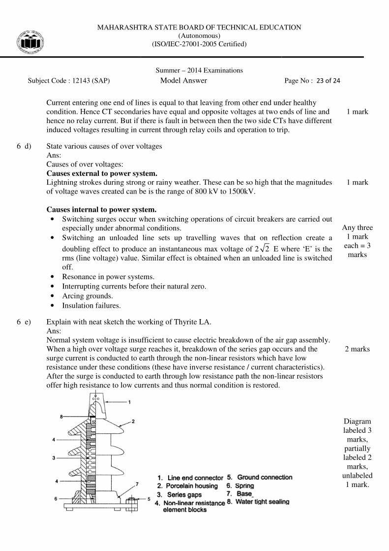
6 e) Explain with neat sketch the working of Thyrit
Ans:
Normal system voltage is insuffici
When a high over voltage surge reaches it, breakdown of the series gap occurs and the
surge current is conducted to earth through the
resistance under these conditions (
After the surge is conducted to earth through low resistance path the non
offer high resistance to low currents and thus normal condition is restored.
MAHARASHTRA STATE BOARD OF TECHNICAL EDUCATION
(Autonomous)
(ISO/IEC-27001-2005 Certified)
Summer – 2014 Examinations
Subject Code : 12143 (SAP) Model Answer
entering one end of lines is equal to that leaving from other end under healthy
ries have equal and opposite voltages at two ends
if there is fault in between then the two side CTs have different
induced voltages resulting in current through relay coils and operation to trip.
State various causes of over voltages
Causes external to power system.
Lightning strokes during strong or rainy weather. These can be so high that the magnitudes
of voltage waves created can be is the range of 800 kV to 1500kV.
Causes internal to power system.
Switching surges occur when switching operations of circuit breakers are carried out
especially under abnormal conditions.
Switching an unloaded line sets up travelling waves that on reflection create a
doubling effect to produce an instantaneous max voltage of 2 2 E where ‘E’ is the
rms (line voltage) value. Similar effect is obtained when an unloaded line is switched
in power systems.
Interrupting currents before their natural zero.
with neat sketch the working of Thyrite LA.
is insufficient to cause electric breakdown of the air gap assembly
a high over voltage surge reaches it, breakdown of the series gap occurs and the
ducted to earth through the non-linear resistors which have low
resistance under these conditions (these have inverse resistance / current characteristics
the surge is conducted to earth through low resistance path the non-linear
w currents and thus normal condition is restored.
MAHARASHTRA STATE BOARD OF TECHNICAL EDUCATION
Page No : 23 of 24
entering one end of lines is equal to that leaving from other end under healthy
ies have equal and opposite voltages at two ends of line and
if there is fault in between then the two side CTs have different
operation to trip.
1 mark
Lightning strokes during strong or rainy weather. These can be so high that the magnitudes
Switching surges occur when switching operations of circuit breakers are carried out
up travelling waves that on reflection create a
E where ‘E’ is the
rms (line voltage) value. Similar effect is obtained when an unloaded line is switched
1 mark
Any three
1 mark
each = 3
marks
breakdown of the air gap assembly.
a high over voltage surge reaches it, breakdown of the series gap occurs and the
linear resistors which have low
characteristics).
linear resistors
2 marks
Diagram
labeled 3
marks,
partially
labeled 2
marks,
unlabeled
1 mark.
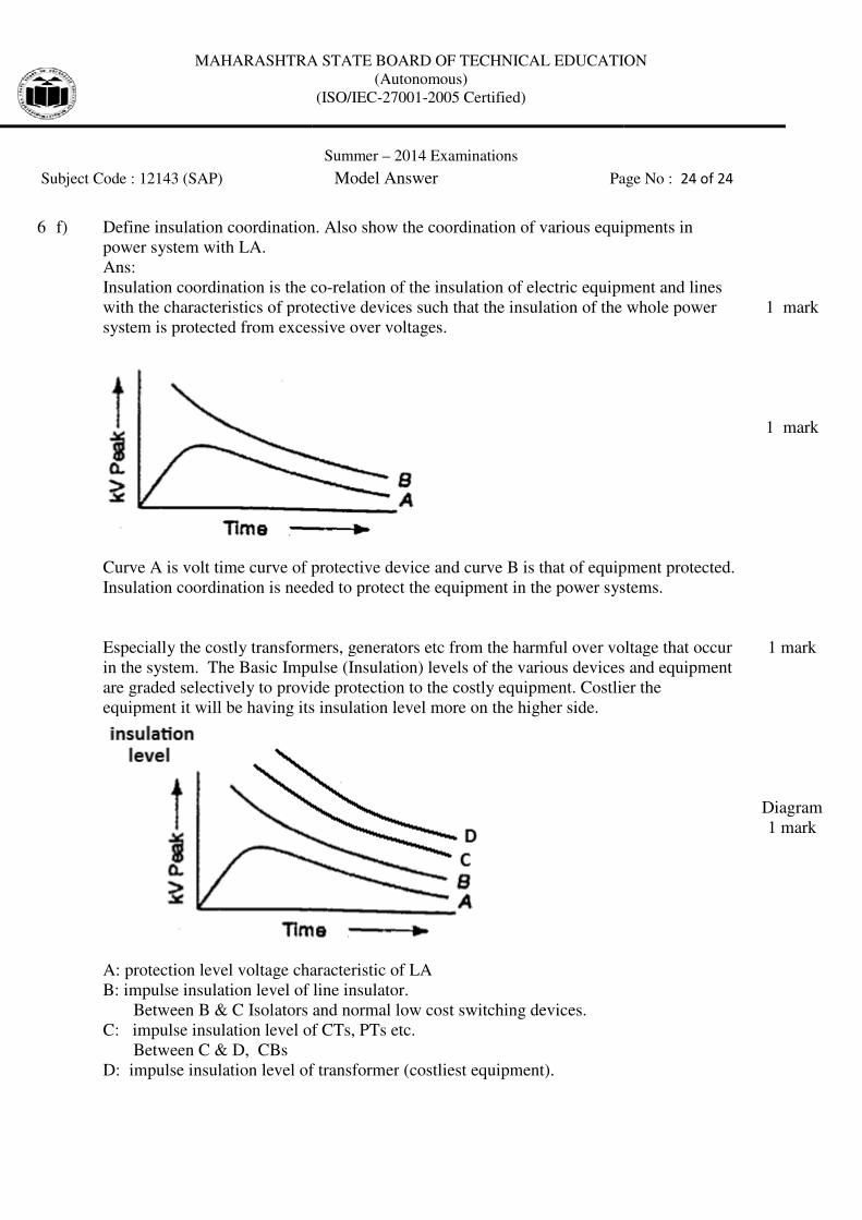
MAHARASHTRA STATE BOARD OF TECHNICAL EDUCATION
Subject Code : 12143 (SAP)
6 f) Define insulation coordination.
power system with LA.
Ans:
Insulation coordination is the co
with the characteristics of protective devices such that the insulation of the whole power
system is protected from excessive over voltages.
Curve A is volt time curve of protective device and curve B is that of equipment protected.
Insulation coordination is needed to protect the e
Especially the costly transformers, generators etc from the harmful over voltage that occur
in the system. The Basic Impulse (Insulation) levels of the various devices and equipment
are graded selectively to provide protection to the costly equipment.
equipment it will be having its insulation level more on
A: protection level voltage characteristic of LA
B: impulse insulation level of
Between B & C Isolators and
C: impulse insulation level of
Between C & D, CBs
D: impulse insulation level of transformer
MAHARASHTRA STATE BOARD OF TECHNICAL EDUCATION
(Autonomous)
(ISO/IEC-27001-2005 Certified)
Summer – 2014 Examinations
Subject Code : 12143 (SAP) Model Answer Page No :
e insulation coordination. Also show the coordination of various equipme
Insulation coordination is the co-relation of the insulation of electric equipment and lines
with the characteristics of protective devices such that the insulation of the whole power
is protected from excessive over voltages.
Curve A is volt time curve of protective device and curve B is that of equipment protected.
Insulation coordination is needed to protect the equipment in the power systems.
ly transformers, generators etc from the harmful over voltage that occur
in the system. The Basic Impulse (Insulation) levels of the various devices and equipment
are graded selectively to provide protection to the costly equipment. Costlier
equipment it will be having its insulation level more on the higher side.
voltage characteristic of LA
line insulator.
B & C Isolators and normal low cost switching devices.
of CTs, PTs etc.
of transformer (costliest equipment).
MAHARASHTRA STATE BOARD OF TECHNICAL EDUCATION
Page No : 24 of 24
of various equipments in
relation of the insulation of electric equipment and lines
with the characteristics of protective devices such that the insulation of the whole power
Curve A is volt time curve of protective device and curve B is that of equipment protected.
quipment in the power systems.
ly transformers, generators etc from the harmful over voltage that occur
in the system. The Basic Impulse (Insulation) levels of the various devices and equipment
ostlier the
1 mark
1 mark
1 mark
Diagram
1 mark
Recommended